Operating and Maintenance Instructions - SKT (verdampings) VX... · Operating and Maintenance...
12
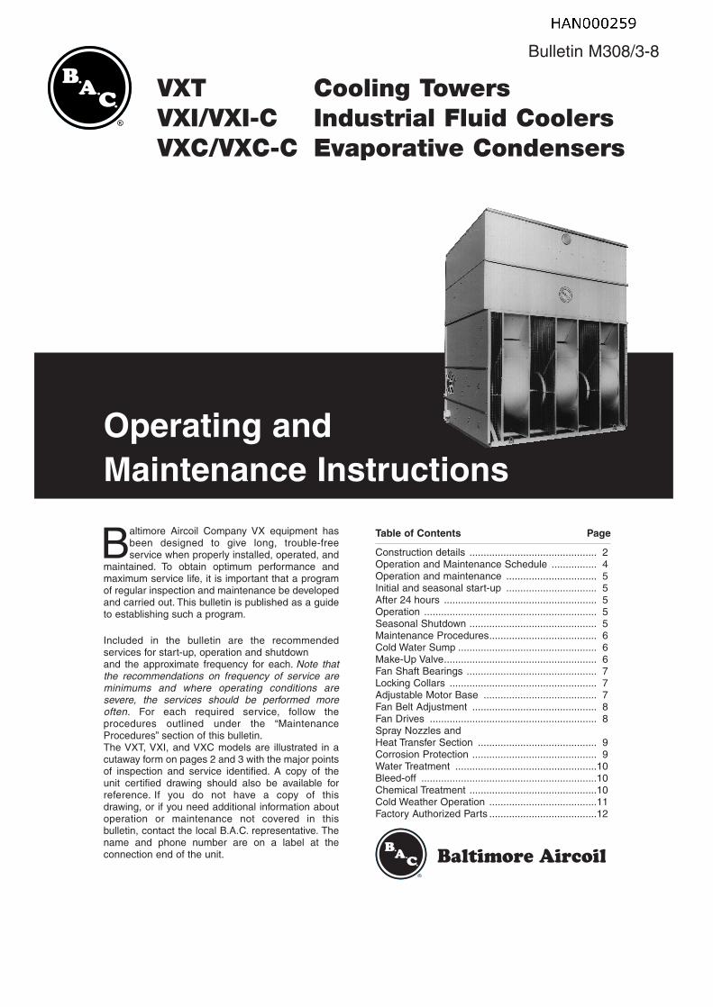
Bulletin M308/3-8 VXT Cooling Towers VXI/VXI-C Industrial Fluid Coolers VXC/VXC-C Evaporative Condensers Operating and Maintenance Instructions B altimore Aircoil Company VX equipment has been designed to give long, trouble-free service when properly installed, operated, and maintained. To obtain optimum performance and maximum service life, it is important that a program of regular inspection and maintenance be developed and carried out. This bulletin is published as a guide to establishing such a program. Included in the bulletin are the recommended services for start-up, operation and shutdown and the approximate frequency for each. Note that the recommendations on frequency of service are minimums and where operating conditions are severe, the services should be performed more often. For each required service, follow the procedures outlined under the “Maintenance Procedures” section of this bulletin. The VXT, VXI, and VXC models are illustrated in a cutaway form on pages 2 and 3 with the major points of inspection and service identified. A copy of the unit certified drawing should also be available for reference. If you do not have a copy of this drawing, or if you need additional information about operation or maintenance not covered in this bulletin, contact the local B.A.C. representative. The name and phone number are on a label at the connection end of the unit. Table of Contents Page Construction details ............................................. 2 Operation and Maintenance Schedule ................ 4 Operation and maintenance ................................ 5 Initial and seasonal start-up ................................ 5 After 24 hours ...................................................... 5 Operation ............................................................. 5 Seasonal Shutdown ............................................. 5 Maintenance Procedures...................................... 6 Cold Water Sump ................................................. 6 Make-Up Valve...................................................... 6 Fan Shaft Bearings .............................................. 7 Locking Collars .................................................... 7 Adjustable Motor Base ........................................ 7 Fan Belt Adjustment ............................................ 8 Fan Drives ........................................................... 8 Spray Nozzles and Heat Transfer Section .......................................... 9 Corrosion Protection ............................................ 9 Water Treatment ..................................................10 Bleed-off ..............................................................10 Chemical Treatment .............................................10 Cold Weather Operation ......................................11 Factory Authorized Parts ......................................12
Transcript of Operating and Maintenance Instructions - SKT (verdampings) VX... · Operating and Maintenance...
Bulletin M308/3-8
VXT Cooling TowersVXI/VXI-C Industrial Fluid CoolersVXC/VXC-C Evaporative Condensers
Operating andMaintenance Instructions
Baltimore Aircoil Company VX equipment hasbeen designed to give long, trouble-free service when properly installed, operated, and
maintained. To obtain optimum performance andmaximum service life, it is important that a programof regular inspection and maintenance be developedand carried out. This bulletin is published as a guideto establishing such a program.
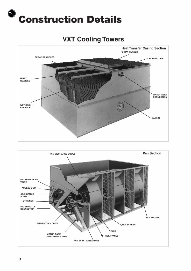
Included in the bulletin are the recommended services for start-up, operation and shutdownand the approximate frequency for each. Note thatthe recommendations on frequency of service areminimums and where operating conditions are severe, the services should be performed moreoften. For each required service, follow the procedures outlined under the “MaintenanceProcedures” section of this bulletin.The VXT, VXI, and VXC models are illustrated in acutaway form on pages 2 and 3 with the major pointsof inspection and service identified. A copy of theunit certified drawing should also be available forreference. If you do not have a copy of this drawing, or if you need additional information aboutoperation or maintenance not covered in this bulletin, contact the local B.A.C. representative. Thename and phone number are on a label at the connection end of the unit.
Table of Contents Page
Construction details ............................................. 2Operation and Maintenance Schedule ................ 4Operation and maintenance ................................ 5Initial and seasonal start-up ................................ 5After 24 hours ...................................................... 5Operation ............................................................. 5Seasonal Shutdown ............................................. 5Maintenance Procedures...................................... 6Cold Water Sump ................................................. 6Make-Up Valve...................................................... 6Fan Shaft Bearings .............................................. 7Locking Collars .................................................... 7Adjustable Motor Base ........................................ 7Fan Belt Adjustment ............................................ 8Fan Drives ........................................................... 8Spray Nozzles andHeat Transfer Section .......................................... 9Corrosion Protection ............................................ 9Water Treatment ..................................................10Bleed-off ..............................................................10Chemical Treatment .............................................10Cold Weather Operation ......................................11Factory Authorized Parts ......................................12
josd
HAN000259
2
Construction Details
Heat Transfer Casing SectionSPRAY HEADER
ELIMINATORS
WATER INLETCONNECTION
CASING
WET DECKSURFACE
SPRAYNOZZLES
SPRAY BRANCHES
VXT Cooling Towers
Pan Section
FAN HOUSING
FAN SCREEN
FANS
AIR INLET VANES
FAN SHAFT & BEARINGS
MOTOR BASEADJUSTING SCREW
FAN MOTOR & DRIVE
STRAINER
ACCESS DOOR
WATER MAKE-UPVALVE
FAN DISCHARGE COWLS
WATER OUTLETCONNECTION
ADJUSTABLEFLOAT
3
Heat Transfer Coil Section
VXI Industrial Fluid CoolersVXC Evaporative Condensers
Pan Section
WATER DISTRIBUTION SECTION
ELIMINATORS
CASING
COIL
SPRAY NOZZLES
COIL OUTLETCONNECTIONS
COIL INLETCONNECTIONS
FAN DISCHARGE COWLS
FAN HOUSING
FAN SCREEN
FANS
AIR INLET VANES
FAN SHAFT AND BEARINGSMOTOR BASEADJUSTING SCREW
FAN DRIVES
FAN MOTOR
WATER BLEEDLINE
SPRAY WATERPUMP
STRAINER
ACCESS DOOR
WATER MAKE-UPVALVE
4
Safety Precautions All electrical, mechanical and rotating machinery constitute a potential hazard, particularly for those not familiar with its design, construction, and operation.Accordingly, adequate safeguards (including use of protective enclosures where necessary) should be taken with this equipment both to safeguard the public (including minors) from injury and to prevent damage to the equipment, its associated system and the premises.Depending upon site conditions, it also may be necessary to install bottom air inlet screens, ladders, safety cages, stairways, access platforms, and handrails and toeboards for the safety and the convenience of authorized service and maintenance personnel.At no time should this equipment be operated without all fan screens, access panels, and access doors in place.The operation, maintenance, and repair of this equipment should be undertaken only by personnel qualified to do so.All such personnel should be thoroughly familiar with the equipment, the associated systems and controls, and the procedures set forth in this manual. Proper care, procedures, and tools must be used in handling, lifting, installing, operating, maintaining and repairing this equipment to prevent personal injury and/or property damage.For the protection of authorized service and maintenance personnel, each fan and pump motor associated with this equipmentshould be installed with a lockable disconnect switch located within sight of the cooling tower, evaporative condenser, or fluid cooler. No service work should be performed on or near the fans, motors, and drives or inside the unit without first ensuring thefan and pump motors have been disconnected and locked out.The recirculating water systems may contain chemicals or biological contaminants, including Legionella, which could be harmful if inhaled or ingested. Accordingly, personnel who may be exposed directly to the discharge airstream and the associated drift, mists generated during operation of the water distribution systems and/or fans, or mists produced by high pressure water jets or compressed air should these be used to clean portions or components of the recirculating water system,should wear half-face respirators with filter cartridges. When VX-equipment is controlled with a variable fan speed control device, steps must be taken to avoid operating at or near to a fan’s “critical speed”. Consult with your local B.A.C. Representativeon any application utilizing variable speed control to determine whether any critical speed may be encountered.Warning : PVC eliminators, installed in some untis, do not serve as support for persons, nor for storing or workingsurface of toolsand equipment. Use of the plastic eliminators as walk-, werk- or storing surface can lead to damage of the unit and injuries topersonnel. Units with PVC eliminators can not be covered with clear plastic foil.Warranties Please refer to the Limitation of Warranties applicable to and in affect at the time of the sale/purchase of these products.Freeze Protection These products must be protected against damage and/or reduced effectiveness due to possible freeze-up by mechanical and operational methods. Please refer to the Cold Weather Operation guidelines (page 11) or contact the local B.A.C. representative for recommended protection alternatives.
GeneralInformation
OPERATING CONDITIONS
Evaporative Fluid CoolersEvaporative Fluid Coolers are designed for operatingconditions specified below. The operator must ensure that during operation of the equipment theseconditions are not exceeded.Fluid Compatibility : Fluids circulated through the coil(s) of Evaporative Fluid Coolers must be compatible with the coil construction material, i.e.- black steel for standard coils hot dip galvanized
after construction- stainless steel AISI 304L or AISI 316L (options)- galvanized steel for cleanable coil optionDesign pressure : max 10 barMaximum inlet temperature of fluid : 82°CMinimum outlet temperature of fluid : 10°C
Evaporative CondensersEvaporative Condensers are designed for operatingconditions specified below. The operator must ensure that during operation of the equipment theseconditions are not exceeded.Acceptable Refrigerants : R-717, HalocarbonRefrigerants and HFC’sCoil design pressure : 22 bar max. (Note that highpressure coils with a design pressure of 28 bar areavailable upon request.)Maximum temperature of superheated vapour : 120°CMinimum temperature of refrigerant in coil(s) : -20°C
SPRAY PRESSURE
Maximum pressure at the inlet of the spray water
distribution system is not to exceed 14 kPa. Standardspray water pumps supplied and installed by B.A.C.do not exceed this pressure limit and require noextra installation of pressure gauges. For pumpssupplied by others (remote sump) it is recommendedto install a pressure gauge at the inlet of the waterdistribution system.
CONNECTING PIPING
All refrigerant piping external to the evaporative condenser(s) must be supported separately from theequipment. In case the evaporative condenser(s) areinstalled in vibration rails or springs, the piping mustcontain compensators to eliminate vibrations carriedthrough the refrigerant piping.
PURGE REQUIREMENTS
The installer of this equipment must ensure propersystem purging of air, prior to operation of the installation. Air entrained in the system can obstructthe proper drainage of liquid refrigerant, reduce condensing capacity and result in higher operatingpressures than design. To verify absence of non con-densibles in the system, follow the instructions of theB.A.C. Evaporative Condenser Manual E115.
REFRIGERANT CONNECTIONS ON SITE
All connections in the external refrigerant pipework(installed by others) must be leak free and testedaccordingly.
TYPE SERVICE
Inspect General Condition of Unit
Clean Debris from Unit
Clean and Flush Sump
Clean Sump Strainer
Check and Adjust Sump Water Level
Inspect Heat Transfer Section
Inspect Spray Nozzles
Check and Adjust Fan Belt Tension
Check and Adjust Bleed Rate
Check Operation of Make-Up Valve
Check Unit for Unusual Noise or Vibration
Check Fan Bearing Locking Collars
Check Motor Voltage and Current
Lubricate Fan Shaft Bearings
Lubricate Motor Base Adjusting Screw
Check Fan for Rotation Without Obstruction
Check Fan and Pump Motor for Proper Rotation
Drain Sump and Piping
Inspect Protective Finish
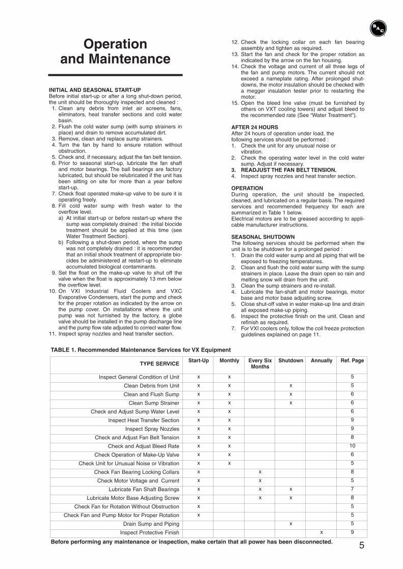
TABLE 1. Recommended Maintenance Services for VX Equipment
Start-Up Monthly Every Six Shutdown Annually Ref. PageMonths
x x 5
x x x 5
x x x 6
x x x 6
x x 6
x x 9
x x 9
x x 8
x x 10
x x 6
x x 5
x x 8
x x 5
x x x 7
x x x 8
x 5
x 5
x 5
x 9
Before performing any maintenance or inspection, make certain that all power has been disconnected. 5
Operationand Maintenance
INITIAL AND SEASONAL START-UPBefore initial start-up or after a long shut-down period,the unit should be thoroughly inspected and cleaned :1. Clean any debris from inlet air screens, fans,
eliminators, heat transfer sections and cold waterbasin.
2. Flush the cold water sump (with sump strainers inplace) and drain to remove accumulated dirt.
3. Remove, clean and replace sump strainers.4. Turn the fan by hand to ensure rotation without
obstruction.5. Check and, if necessary, adjust the fan belt tension.6. Prior to seasonal start-up, lubricate the fan shaft
and motor bearings. The ball bearings are factorylubricated, but should be relubricated if the unit hasbeen sitting on site for more than a year beforestart-up.
7. Check float operated make-up valve to be sure it isoperating freely.
8. Fill cold water sump with fresh water to the overflow level.a) At initial start-up or before restart-up where the
sump was completely drained : the initial biocidetreatment should be applied at this time (seeWater Treatment Section).
b) Following a shut-down period, where the sumpwas not completely drained : it is recommendedthat an initial shock treatment of appropriate bio-cides be administered at restart-up to eliminateaccumulated biological contaminants.
9. Set the float on the make-up valve to shut off thevalve when the float is approximately 13 mm belowthe overflow level.
10. On VXI Industrial Fluid Coolers and VXCEvaporative Condensers, start the pump and checkfor the proper rotation as indicated by the arrow onthe pump cover. On installations where the unitpump was not furnished by the factory, a globevalve should be installed in the pump discharge lineand the pump flow rate adjusted to correct water flow.
11. Inspect spray nozzles and heat transfer section.
12. Check the locking collar on each fan bearingassembly and tighten as required.
13. Start the fan and check for the proper rotation asindicated by the arrow on the fan housing.
14. Check the voltage and current of all three legs of the fan and pump motors. The current should notexceed a nameplate rating. After prolonged shut-downs, the motor insulation should be checked witha megger insulation tester prior to restarting themotor.
15. Open the bleed line valve (must be furnished byothers on VXT cooling towers) and adjust bleed tothe recommended rate (See “Water Treatment”).
AFTER 24 HOURSAfter 24 hours of operation under load, the following services should be performed :1. Check the unit for any unusual noise or
vibration.2. Check the operating water level in the cold water
sump. Adjust if necessary.3. READJUST THE FAN BELT TENSION.4. Inspect spray nozzles and heat transfer section.
OPERATIONDuring operation, the unit should be inspected, cleaned, and lubricated on a regular basis. The requiredservices and recommended frequency for each aresummarized in Table 1 below.Electrical motors are to be greased according to appli-cable manufacturer instructions.
SEASONAL SHUTDOWNThe following services should be performed when theunit is to be shutdown for a prolonged period :1. Drain the cold water sump and all piping that will be
exposed to freezing temperatures.2. Clean and flush the cold water sump with the sump
strainers in place. Leave the drain open so rain andmelting snow will drain from the unit.
3. Clean the sump strainers and re-install.4. Lubricate the fan-shaft and motor bearings, motor
base and motor base adjusting screw.5. Close shut-off valve in water make-up line and drain
all exposed make-up piping.6. Inspect the protective finish on the unit. Clean and
refinish as required.7. For VXI coolers only, follow the coil freeze protection
guidelines explained on page 11.
6
MaintenanceProcedures
COLD WATER SUMP
The cold water sump should be inspected regularly.Any trash or debris which may have accumulated inthe sump or on the strainers should be removed.
Each month, the entire cold water sump should bedrained, cleaned and flushed with fresh water toremove the silt and sediment which normally collectsin the sump during operation. If not removed periodically, this sediment can become corrossiveand cause deterioration of the protective finish.When flushing the sump, the strainers should be leftin place to prevent the sediment from re-enteringsystem. After the sump has been fushed, the strainers should be removed, cleaned, and replacedbefore refilling the sump with fresh water. The strainers can be removed by pulling the handle upand away from the outlet connection.
Note : Do not use acid to clean the strainers.
MAKE-UP VALVE
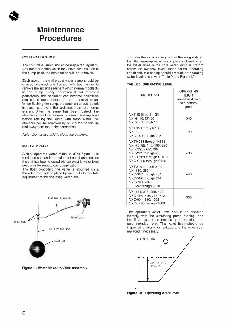
A float operated water make-up (See figure 1) is furnished as standard equipment on all units unlessthe unit has been ordered with an electric water levelcontrol or for remote sump application.The float controlling the valve is mounted on a threaded rod, held in place by wing nuts to facilitateadjustment of the operating water level.
Figure 1 - Water Make-Up Valve Assembly
To make the initial setting, adjust the wing nuts sothat the make-up valve is completely closed whenthe water level in the cold water sump is 13 mmbelow the overflow level. Under normal operatingconditions, this setting should produce an operatingwater level as shown in Table 2 and Figure 1A.
TABLE 2. OPERATING LEVEL
MODEL NO
VXT-10 through 135VXI-9, 18, 27, 36VXC-14 through 135
VXT-150 through 185VXI-50VXC-150 through 205
VXT-N215 through N535VXI-70, 95, 145, 190, 290VXI-C72, VXI-C108VXC-221 through 265VXC-S288 through S1010VXC-C220 through C425
VXT-315 through 2400VXI-180, 360VXC-357 through 454VXC-562 through 714VXC-798, 908
1124 through 1360
VXI-144, 215, 288, 430VXC-495, 516, 715, 772VXC-804, 990, 1032VXC-1430 through 1608
OPERATINGHEIGHT
(measured frompan bottom)
(mm)
340
420
430
460
350
The operating water level should be checkedmonthly, with the circulating pump running, and the float ajusted as necessary to maintain therecommended level. The valve itself should be inspected annually for leakage and the valve seatreplaced if necessary.
Figure 1A - Operating water level
Float Arm Assembly
Float Valve
Wing nuts
All Threaded Rod
Float BallOVERFLOW
OPERATINGHEIGHT
7
MaintenanceProcedures
(continued)
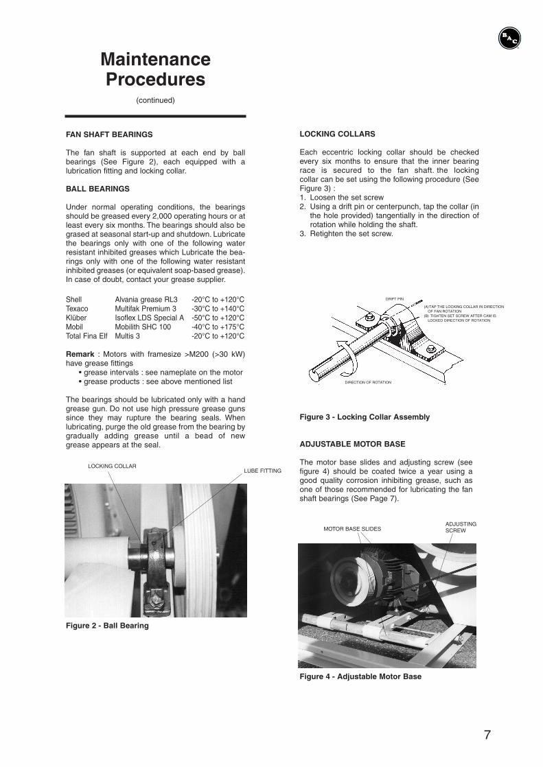
FAN SHAFT BEARINGS
The fan shaft is supported at each end by ball bearings (See Figure 2), each equipped with a lubrication fitting and locking collar.
BALL BEARINGS
Under normal operating conditions, the bearingsshould be greased every 2,000 operating hours or atleast every six months. The bearings should also begrased at seasonal start-up and shutdown. Lubricatethe bearings only with one of the following waterresistant inhibited greases which Lubricate the bea-rings only with one of the following water resistantinhibited greases (or equivalent soap-based grease).In case of doubt, contact your grease supplier.
Shell Alvania grease RL3 -20°C to +120°CTexaco Multifak Premium 3 -30°C to +140°CKlüber Isoflex LDS Special A -50°C to +120°CMobil Mobilith SHC 100 -40°C to +175°CTotal Fina Elf Multis 3 -20°C to +120°C
Remark : Motors with framesize >M200 (>30 kW)have grease fittings
• grease intervals : see nameplate on the motor• grease products : see above mentioned list
The bearings should be lubricated only with a handgrease gun. Do not use high pressure grease gunssince they may rupture the bearing seals. Whenlubricating, purge the old grease from the bearing bygradually adding grease until a bead of new grease appears at the seal.
Figure 2 - Ball Bearing
LOCKING COLLARLUBE FITTING
LOCKING COLLARS
Each eccentric locking collar should be checkedevery six months to ensure that the inner bearingrace is secured to the fan shaft. the locking collar can be set using the following procedure (See Figure 3) :1. Loosen the set screw2. Using a drift pin or centerpunch, tap the collar (in
the hole provided) tangentially in the direction ofrotation while holding the shaft.
3. Retighten the set screw.
Figure 3 - Locking Collar Assembly
ADJUSTABLE MOTOR BASE
The motor base slides and adjusting screw (seefigure 4) should be coated twice a year using agood quality corrosion inhibiting grease, such asone of those recommended for lubricating the fanshaft bearings (See Page 7).
Figure 4 - Adjustable Motor Base
DRIFT PIN
(A)TAP THE LOCKING COLLAR IN DIRECTIONOF FAN ROTATION
(B) TIGHTEN SET SCREW AFTER CAM ISLOCKED DIRECTION OF ROTATION
DIRECTION OF ROTATION
MOTOR BASE SLIDESADJUSTINGSCREW

8
MaintenanceProcedures
(continued)
TABLE : BELT TENSION FORCES
Figure 6 - Checking Sheave Alignment
BELT PROFILE DIAMETER (mm) DEFLECTION FORCE (kg)MOTOR SHEAVE min. max.
XPA 80 through 125 1.5 2.5132 through 200 2.0 3.0
> 200 2.5 3.5
SPA 100 through 125 1.5 2.0132 through 212 2.0 2.5
> 212 2.0 3.0
New belts have to be retensioned after 24 hoursoperation.
The DRIVE ALIGNMENT should be checkedannually to ensure maximum belt life. This is done byplacing a straightedge across both sheaves asshown in Figure 6.
When the drives are properly aligned the gap measured between straightedge and sheave doesnot exceed 0,5 mm per 100 mm of sheave diameter.
Ex. : motor sheave has ø 150 mm and fan sheavehas ø 500 mmMax. gap on motorsheave 1,5 x 0,5 = 0,75 mmMax. gap on fan sheave 5 x 0,5 = 2,5 mm
MOTORSHEAVE
FAN SHEAVE
STRAIGHTEDGE
POINT OF CONTACT
FAN DRIVES
The fan BELT TENSION should be checked, ifnecessary adjusted, every month.The position of thefan motor can be changed to achieve this by rotatingthe motor base adjusting screw which extendsthrough the bottom frame angel.
Remark : Rotate the fan sheave half a turn to evenlydistribute the tension in the belt beforemeasuring.
The belt tension is correct if following conditions areboth met :
a. the deflection amounts 10 mm/m free belt length(see figure 5)f.e. the deflection is 8 mm for a free belt length of
0,8 m.the deflection is 12 mm for a free belt lengthof 1,2 m.
b. the deflection force required is between the min.& max. values given in the table herewith for thebelt type & sheave size concerned.
Figure 5 - Fan Belt Adjustment
9
MaintenanceProcedures
(continued)
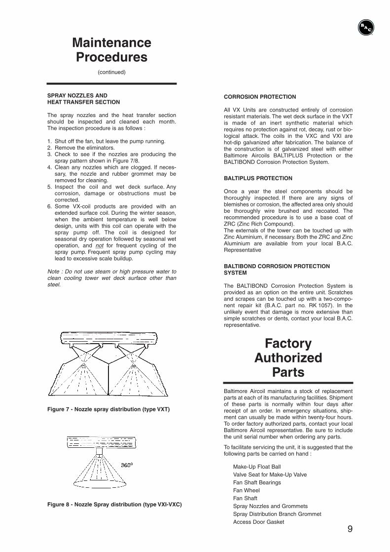
SPRAY NOZZLES ANDHEAT TRANSFER SECTION
The spray nozzles and the heat transfer sectionshould be inspected and cleaned each month.The inspection procedure is as follows :
1. Shut off the fan, but leave the pump running.2. Remove the eliminators.3. Check to see if the nozzles are producing the
spray pattern shown in Figure 7/8.4. Clean any nozzles which are clogged. If neces-
sary, the nozzle and rubber grommet may beremoved for cleaning.
5. Inspect the coil and wet deck surface. Any corrosion, damage or obstructions must becorrected.
6. Some VX-coil products are provided with anextended surface coil. During the winter season,when the ambient temperature is well belowdesign, units with this coil can operate with thespray pump off. The coil is designed for seasonal dry operation followed by seasonal wetoperation, and not for frequent cycling of thespray pump. Frequent spray pump cycling maylead to excessive scale buildup.
Note : Do not use steam or high pressure water toclean cooling tower wet deck surface other thansteel.
Figure 7 - Nozzle spray distribution (type VXT)
Figure 8 - Nozzle Spray distribution (type VXI-VXC)
CORROSION PROTECTION
All VX Units are constructed entirely of corrosionresistant materials. The wet deck surface in the VXTis made of an inert synthetic material which requires no protection against rot, decay, rust or bio-logical attack. The coils in the VXC and VXI are hot-dip galvanized after fabrication. The balance ofthe construction is of galvanized steel with eitherBaltimore Aircoils BALTIPLUS Protection or theBALTIBOND Corrosion Protection System.
BALTIPLUS PROTECTION
Once a year the steel components should be thoroughly inspected. If there are any signs of blemishes or corrosion, the affected area only shouldbe thoroughly wire brushed and recoated. Therecommended procedure is to use a base coat ofZRC (Zinc Rich Compound).The externals of the tower can be touched up withZinc Aluminium, if necessary. Both the ZRC and ZincAluminium are available from your local B.A.C.Representative
BALTIBOND CORROSION PROTECTIONSYSTEM
The BALTIBOND Corrosion Protection System isprovided as an option on the entire unit. Scratchesand scrapes can be touched up with a two-compo-nent repair kit (B.A.C. part no. RK 1057). In the unlikely event that damage is more extensive thansimple scratches or dents, contact your local B.A.C.representative.
FactoryAuthorized
PartsBaltimore Aircoil maintains a stock of replacementparts at each of its manufacturing facilities. Shipmentof these parts is normally within four days afterreceipt of an order. In emergency situations, ship-ment can usually be made within twenty-four hours.To order factory authorized parts, contact your localBaltimore Aircoil representative. Be sure to includethe unit serial number when ordering any parts.
To facilitate servicing the unit, it is suggested that thefollowing parts be carried on hand :
Make-Up Float BallValve Seat for Make-Up ValveFan Shaft BearingsFan WheelFan ShaftSpray Nozzles and GrommetsSpray Distribution Branch GrommetAccess Door Gasket

10
WaterTreatment
Evaporative cooling is accomplished by the evaporation of a portion of water being recirculated.As water evaporates, the dissolved solids originallypresent in the water remain in the system.The concentration of dissolved solids increasesrapidly and can reach unacceptable levels.In addition, airborne impurities and biological contaminants are often introduced into the recircula-ting water. If impurities and contaminants are noteffectively controlled, they can cause scaling, corrosion, sludge or biological fouling, which reduceheat transfer efficiency and increase system operating costs.For optimal heat transfer efficiency and maximumequipment life, the quality of the recirculating watershould be maintained within the guidelines listedbelow :
Circulated Water Quality Guidelines
BALTIBONDCorrosion-
Protection system
BALTIPLUSProtection
pH
Hardness as(CaCO3)
Alkalinity as(CaCO3)
Total DissolvedSolids
Chlorides
Sulfates
6.5 to 9.0 7.0 to 9.0
30 to 500 ppm 30 to 500 ppm
500 ppm max. 500 ppm max.
1200 ppm max. 1000 ppm max.
250 ppm max. 125 ppm max.
250 ppm max. 125 ppm max.
To prevent an excessive buildup of impurities in therecirculating water, it is recommended that a smallamount of water be «bled» from the unit at a rate at least equal to the amount of water being evaporated (i.e., a rate that will maintain approximately two cycles of concentration in the circulating water). In many localities, this constantbleed and replacement with fresh water will keep theconcentration of impurities in the system at anacceptable level.
The evaporation rate can be determined by one ofthe following :1. The evaporation rate is approximately 1,8 l per
1000 kcal of heat rejection.2. The evaporation rate is approximately 1,8 l per
4180 kJ.3. Evaporative rate = Water Flow Rate (l/s) x Range
(0°C) x 0,0018Exemple : At a flow rate of 10 l/s and a cooling rangeof 10°C the evaporation rate is 0,18 l/s(10 l/s x 10°C x 0,0018 = 0,18 l/s)
Note : For VXI, the flow rate is the flow through thecoil.
The rate of bleed-off can be adjusted with the valveand measured by filling a gallon container whilenoting the time period. The bleed-off rate should bechecked periodically to ensure that proper waterquality is being maintained.
Note : the bleed line must be furnished by others oncooling tower models VXT-N215 through VXT-4800.
CHEMICAL TREATMENT
If the condition of the water is such that constantbleed-off will not control scale or corrosion, andmaintain the water quality within the guidelines, chemical treatment may be necessary. If a water treatment program is used it must meet the following requirements :
1. The chemicals must be compatible with galvanized (zinc coated) steel. Water treatmentchemicals which are compatible with galvanizedsteel are also satisfactory for the Zinc Aluminumfinish.
2. Chemicals should be fed into the recirculatedwater, but not into the cold water sump, on a continuous metered basis to avoid localized highconcentrations which may cause corrosion.These chemicals are normally fed into the pumpdischarge line. Batch feeding of chemicals doesnot afford adequate control of water quality and isnot recommended.
3. Acid water treatment is not recommended forunits furnished with Zinc Aluminum finish. VXCooling Towers provided with the BALTIBONDCorrosion Protection System on the entire unit(designated with an «R» suffix on the nameplate,VXT-400R) may be used on systems with acidwater treatment as long as requirements 1 and 2 listed above are maintained.
BIOLOGICAL CONTROL
Bleed- off with or without chemical treatment forscale and corrosion control is not adequate for control of biological contamination. The growth of algae, slimes, and other micro-organisms, ifunchecked, will reduce system efficiency and maycontribute to the growth of potentially harmful micro-organisms, including Legionella, in the recirculating water system.
Accordingly, a treatment program specifically designed to address biological control should be initiated when the system is first filled with water andadministered on a regular basis thereafter in accordance with the suppliers instructions. Liquidbiocides may be added to the sump of the coolingtower in dilute form. If the solid form of biocide isused, it should be added to the system via a pot feeder.
For specific recommendations on treatment forscale, corrosion, or biological control, consult a competent water treatment supplier.

11
Cold WeatherOperation
VX equipment can be operated in subfreezingambient conditions provided the proper measuresare taken :1. Protection against pan water freezing when the
unit is idle.2. Capacity control to prevent ice formation and heat
transfer sections during operation.3. Protection against coil freezing (VXI Industrial
Fluid Coolers).
Cold weather applications should be reviewed withthe B.A.C. representative in your area to ensure thatthe unit selection, location, control and accessoriesare adequate to ensure reliable operation. Listedbelow are general guidelines which should be followed to minimize the possibility of freeze-up.
PROTECTION AGAINSTPAN WATER FREEZING
When the unit is shutdown and exposed to sub-freezing ambient temperatures, the pan water may freeze. A remote sump located in a heated indoorarea is a desirable method of freeze protection.Alternatively, pan heaters (electric immersion heaters) can be used to maintain the pan water at aminimum temperature of 4°C. In addition to protecting the cold water basin, all exposed waterpiping including pump piping below the overflow leveland make-up water lines should be traced with elec-trical heater tape and insulated
CAPACITY CONTROL
It is necessary to prevent the recirculating water fromapproaching freezing conditions when the unit isoperating under load.
At times the unit is provided with the BALTIGUARDFan System for Capacity Control. A full size fanmotor and drive are installed at one end of the fanshaft and a lower horsepower motor (sized at approximately one-third the horsepower of a standard motor, with drives designed for approxima-tely 2/3 of design fan speed) is installed at the opposite end. This allows the fans to operate at 2/3speed at lower ambient conditions. Please note thatcapacity control dampers allow the unit to operatelonger and with closer control than the BALTIGUARD Fan System and/or fan cycling.
Multiple fan motors serving a single coil section mustbe cycled simultaneously. This applies to the VXI-180 and 360. With 2-speed motors, there shouldbe a 15 second time delay during switch down fromhigh to low speed to avoid overloads on the lowspeed windings of the motor.
PROTECTION AGAINST COIL FREEZING(VXI ONLY)
Evaporative Fluid Cooler coil(s) must be protectedfrom damage by freezing of the fluid inside the coil(s)when exposed to subfreezing conditions. Freeze pro-tection can be obtained by the use of ethylene orpropylene glycol or other anti freeze solutions inappropriate concentrations. In such cases refer tothe appropriate selection method in the technicalbulletin D405.When an antifreeze solution is not possible, the sys-tem must be operated to meet both of the followingconditions :1. Maintain the minimum recommended flow
through the unit at all times.
MODEL NO. MINIMUM FLOW (l/s)
VXI-9, 18, 27, 36VXI-50VXI-70VXI-C72VXI-C108VXI-95, 145VXI-144, 215VXI-180VXI-190, 290VXI-288, 430VXI-360
3,557788
1311162622
2. Maintain the heat load on the circulating fluid sothat the temperature of the fluid leaving the coilwill not fall below 10°C.
If the process load is extremely light or shut off, itmay be necessary to apply an auxiliary heat load circulating fluid at 10°C when freezing conditionsexist.*
Draining the coil is not recommended as a normalmethod of freeze protection. Frequent draining promotes corrosion inside the coil tubes. However,draining is acceptable as an emergency method offreeze protection if the coil is not protected by anantifreeze solution. The local B.A.C. representativeshould be consulted for guidelines on the installation of an emergency coil drain system.
* For evaporative chilling applications only, the leaving fluid temperature can be maintained as lowas 8°C. Consult the local B.A.C. representative fornecessary precautions.
Baltimore AircoilBALTIMORE AIRCOIL INTERNATIONAL N.V., Industriepark - Zone A, B-2220 Heist-op-den-Berg, BelgiumBALTIMORE AIRCOIL LTD., Princewood Road, Corby, Northants, NN17 4AP, U.K.BALTIMORE AIRCOIL ITALIA S.R.L., Località Giardini, 23030 Chiuro (Sondrio), ItalyBALTIMORE AIRCOIL IBERICA, S.A., Avenida de Burgos 14, Bloque 3, 2°D, 28036 Madrid, Spain
www.BaltimoreAircoil.be [email protected]
Printed in Belgium
ONE OF THE
I N D U S T R I E S