
OPERATING AND MAINTENANCE INSTRUCTIONS - · PDF fileOPERATING AND MAINTENANCE INSTRUCTIONS...
16
Double column Double column PAINTING EQUIPMENT OPERATING AND MAINTENANCE INSTRUCTIONS ENGLISH OPERATING AND MAINTENANCE INSTRUCTIONS
Transcript of OPERATING AND MAINTENANCE INSTRUCTIONS - · PDF fileOPERATING AND MAINTENANCE INSTRUCTIONS...

Double columnDouble column
PAINTING EQUIPMENT
OPE
RATI
NG A
NDM
AINT
ENAN
CE IN
STRU
CTIO
NS
ENGLISHOPE
RATI
NG A
NDM
AINT
ENAN
CE IN
STRU
CTIO
NS


1
RAM
English
DOUBLE COLUMN PNEUMATIC RAMDOUBLE COLUMN PNEUMATIC RAM
Thank you for choosing a LARIUS s.r.l.As well as the product purchased,
you will receive a range of support servicesenabling you to achieve the results desired,
quickly and professionally.
WORKING PRINCIPLE ......................................p.1
WARNINGS ........................................................p.2
WORKING PRINCIPLE ......................................p.3
TECHNICAL DATA ..............................................p.3
DESCRIPTION OF THE EQUIPMENT ...............p.4
SAFETY RULES .................................................p.6
SETTING-UP ......................................................p.6
WORKING ..........................................................p.7
REPLACEMENT OF THE DRUM .......................p.10
ROUTIN MAINTENANCE ...................................p.11
PROBLEMS AND SOLUTION ............................p.11
SPARE PARTS ...................................................p.12
VERSIONS .........................................................p.13
WE ADVISE THE USE OF THIS EQUIPMENT ONLY BY PROFESSIONAL OPERATORS.ONLY USE THIS MACHINE FOR USAGE SPECIFICALLY MENTIONED IN THIS MANUAL.
ABCDE
FGHI
L
M
2
RAM
Engl
ish
Read this operator’s manual carefully before using the equipment.An improper use of this machine can cause injuries to people or things.Do not use this machine when under the infl uence of drugs or alcohol.Do not modify the equipment under any circumstances.Use products and solvents that are compatible with the various parts of the equipment, and read the manufacturer’s warnings care-fully.See the Technical Details for the equipment given in the Manual.Check the equipment for worn parts once a day. If any worn parts are found, replace them using ONLY original spare parts.Keep children and animals away from work area.Comply with all safety standards.
It indicates an accident risk or serious damage to equipment if this warning is not followed.
It indicates important recommendations about disposal and recycling process of products in accordance with the environmental regulations.
WARNINGS The table below provides the meaning of the symbols used in this manual in relation to using, earthing, operating, maintaining, and repairing of this equipment.
It indicates a fi re or explosion risk if this warning is not followed.Eliminate all ignition sources such as pilot lights, cigarettes, portable electric lamps and plastic drop cloths.Keep work area free of debris.ONLY use this equipment in a well ventilated area.EARTH ALL THE EQUIPMENT LOCATED IN THE WORK AREA.Do not form connections or switch light switches on or off if the air contains infl ammable fumes.If electrical shocks or discharges are encountered the operation being carried out using the equipment must be stopped immedia-tely.Keep a fi re extinguisher at hand in the immediate vicinity of the work area.
It indicates wound and fi nger squashing risk due to movable parts in the equipment.Tenersi lontano dalle parti in movimento.Do not use the equipment without the proper protection.Before any inspection or maintenance of the equipment, carry out the decompression procedure explained in this manual, and prevent any risk of the equipment starting unexpectedly.
It indicates the danger of carriage unexpected movement on slanting surfaces
Report any danger of electric shock if the warning and presence of live electrical parts has not been indicated.Store in a dry place and do not expose to the rain.Check that the cables are in good condition.Switch off the equipment and discharge any electricity before cleaning or maintaining the equipment.
Mark any clamps attached to earth cables.Use ONLY 3-wire extension cords and grounded electrical outlets.Before starting work make sure that the electrical system is earthed and that it complies with safety standards.
It is obligatory to wear suitable clothing as gloves, goggles and face shield.Wear clothing that complies with the safety standards in force in the country in which the equipment is used.Do not wear bracelets, earrings, rings, chains, or anything else that may hinder the operator’s work.Do not wear clothing with wide sleeves, scarves, ties, or any other piece of clothing that could get tangled up in moving parts of the equipment during the work, inspection, or maintenance cycles.
3
RAM
English
A
B
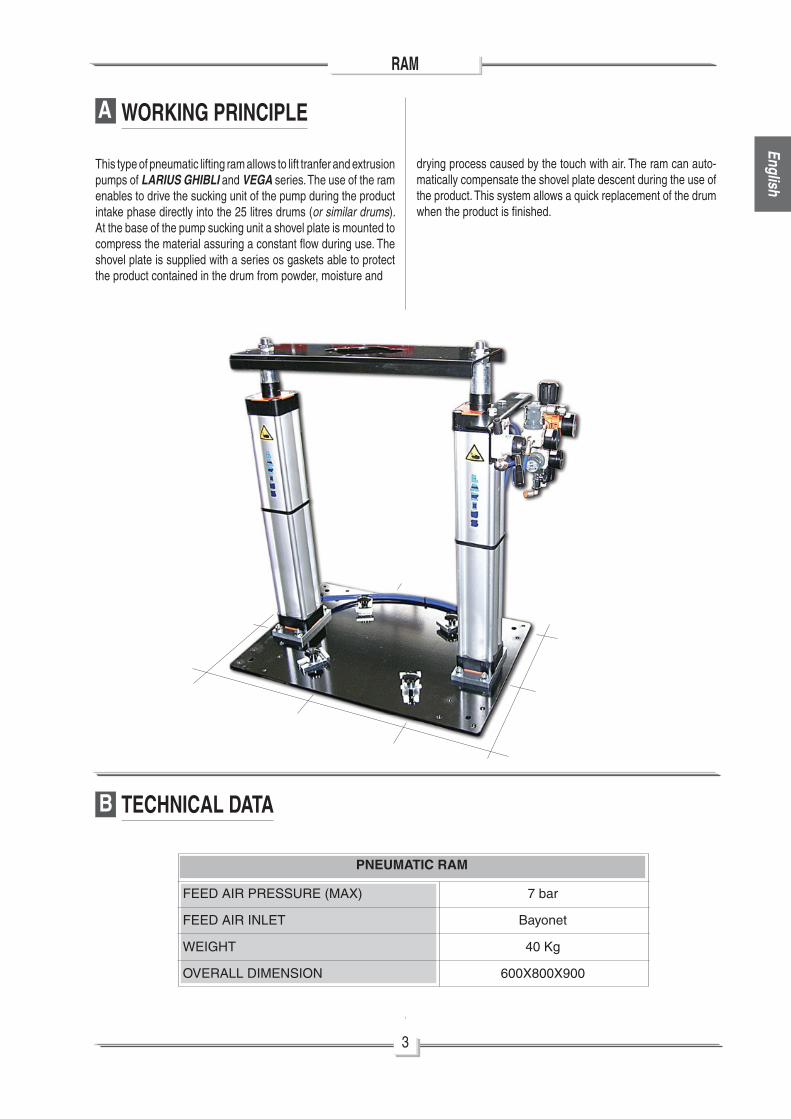
WORKING PRINCIPLE
This type of pneumatic lifting ram allows to lift tranfer and extrusion pumps of LARIUS GHIBLI and VEGA series. The use of the ram enables to drive the sucking unit of the pump during the product intake phase directly into the 25 litres drums (or similar drums). At the base of the pump sucking unit a shovel plate is mounted to compress the material assuring a constant fl ow during use. The shovel plate is supplied with a series os gaskets able to protect the product contained in the drum from powder, moisture and
PNEUMATIC RAM
FEED AIR PRESSURE (MAX)
FEED AIR INLET
WEIGHT
OVERALL DIMENSION
7 bar
Bayonet
40 Kg
600X800X900
drying process caused by the touch with air. The ram can auto-matically compensate the shovel plate descent during the use of the product. This system allows a quick replacement of the drum when the product is fi nished.
TECHNICAL DATA

4
RAM
Engl
ish
C DESCRIPTION OF THE EQUIPMENT
POS.
1
2
3
4
POS.
5
6
7
Lifting cylinders
Pump face
Face for drum product
Control lever (up/down)
Description
Pump air valve
Shovel plate pressure gauge
Shovel plate valve
Description
2
11
3
6
7
5
4

5
RAM
English
POS.
8
9
10
11
POS.
12
13
14
Drum-block
Drum product
Bleeder valve
Shovel plate
Description
Up/down pressure gauge control
Pump pressure gauge
Main air feeder
Description
10
11
12 14 13
8
9

6
RAM
Engl
ish
D SAFETY RULES
E SETTING-UP
The operator will have to arrange an environment suitable to the plant before installing it as indicated here below:
• An area wide enough to allow the drum loading and unloading and routine maintenance operations.
• Ensure there is a suffi cient space in height to enable the ram lifting and easy access to the air regulation groups.
• For the pneumatic ram feeding, use a tube with an internal diameter no lower than 10 mm.
• ALWAYS KEEP CLEAN AND TIDY THE WORK AREA.
• KEEP THOSE WHO ARE NOT RESPONSABLE FOR THE EQUIPMENT OUT OF THE WORK AREA.
• BEFORE USING THE EQUIPMENT, THE OPERATOR MUST BE TRAINED AND INFORMED ABOUT THE POSITION AND WORKING OF ALL THE CONTROLS OF
THE EQUIPMENT.
• NEVER EXCEED THE MAXIMUM WORKING PRESSURE INDICATED.
• RELEASE THE PRESSURE IN THE CIRCUIT BEFORE PERFORMING ANY CHECK OR PART REPLACEMENT OF THE EQUIPMENT.
• NEVER MODIFY PARTS IN THE EQUIPMENT. CHECK REGULARLY THE COMPONENTS OF THE SYSTEM. REPLACE THE PARTS DAMAGED OR WORN.
• TIGHTEN AND CHECK ALL THE FITTINGS FOR CONNECTION BETWEEN PUMP, FLEXIBLE HOSE AND SPRAY GUN BEFORE USING THE EQUIMPENT.
• DO NOT APPROACH TOO MUCH TO THE RAM DURING ITS ASCENT AND DESCENT OPERATIONS.
• BEFORE ANY MAINTENANCE OPERATIONS DISCON-NECT THE ELECTRIC VOLTAGE.
These instructions refer to the correct use of the pneumatic ram. In addition, read caerfully the Instructione contained in the manuals relevant to the different components (pneumatic pump,delivery gun, etc.) which can be used with the ram.
Never spray over fl ammable products or solvents in closed places never use the tooling in presence of potentially explosive gas always check the product is compatible with the materials composing the equipment (pump, spray gun, fl exible hose andaccessories) with which it can come into contact.
When the unit is in operation do not get to close to the mobile parts, in order to avoid possible injuries at the hands or fi ngers.
IF THE PRODUCT TO BE USED IS TOXIC, AVOID INHALATION AND CONTACT BY USINGPROTECTION GLOVES, GOGGLES AND PROPER FACE SHIELDS.
• Make sure the air governors to the pump and ram are closed. (turn counterclockwise the control knob to close them).
• Make sure the air delivery valve to the shovel plate is closed.
• Make sure the air delivery pipe to the pneumatic pump is connected to the ram and to the pump.
• Make sure the air delivery pipe to the shovel plate is connected to the ram and to the shovel plate.
Install a condensate fi lter and a shut-off valve type ON-OFF on the air supply line to the ram.
It indicates the danger of carriage unexpected movement on slanting surfaces

7
RAM
English
F WORKING
• Open the air supply to the ram.
• Turn the lifting control lever (F1) upwards.
• Acting on the air (F2) governor to the ram, gradually increase the feeding pressure to the pneumatic cylinder (F3) till the ram starts lifting. Let the ram reaches its maximum height.
• Remove the cover from the drum (F4) to be used.
Check all the fi ttings for the connection of the dif-ferent components (pump, fl exible hose, gun, etc.) before using the equipment avoid approaching too much to the ram during the ascent anddescent functions.
Check if there are any dents on the drum (F4): they could clock the shovel plate (F5) of the ram inside the drum.
F1
F1
F2
F3
F4
F5
Ram air governor
Upwards

8
RAM
Engl
ish
• Turn the control lever (F1) downwards till the shovel plate (F5) lower near the upper edge of the drum (F4).
• Tighten the drum-block (F6).
• Open the bleeder valve placed (F7) on the shovel plate (F5).
• Place the drum (F4) on the ram’s plate (F6) and tighten the drum-block.
• Stop the descent of the ram by turning the control lever (F1) to the intermediate position.
• Center the drum (F4) correctly so as it ia in axis with the shovel plate (F5).
Downwards
F4
F6
F1
F5 F4
F7
Drum-block
Center the drum
Open the bleeder valve
Stop

9
RAM
English
• Turn the control lever (F1) downwards let the shovel plate (F5) enter into the drum (F4).
• Close the bleeder valve (F7) of the shovel plate (F5).
• Open the air (F8) passage valve on the pneumatic pump (F9).
• Allow thw compressed air fl ow into the pump (F9) acting on the air governor placed on the ram. It is advised to adjust the air pressure to the minimum value necessary to a continuous
working.
• To make the bleed of the pumping, read the pump manual.
• The pump will start working and then will stop when all the chamber of the product is full. The pump will start working any time the trigger of the gun is pushed or the delivery valve is open.
• In case of diffi cult suction of the pump, slowly open the bleeder valve placed (F7) on the shovel plate (F6) and close it when some product comes out from the bleeder fi tting.
Never let the pump idle for a long period: it could damage the pneumtic motor and ruin theseals.
F1
F7
F4
F5
F8
F9
Downwards
Close the bleeder valve
Pump air valve
Air pump regulator

10
RAM
Engl
ish
G REPLACEMENT OF THE DRUM
• Close the air supply to the pump (G1).
• Turn the lifting control lever upwards.
• Gradually open the air delivery valve (G2) to the shovel plate in order to facilitate the extraction of the shovel plate (G3) from the drum (G4).
• Let the ram reach its maximum height.
• Remove the empty drum and replace it with a full one.
G1
G3 G4
G2
Shovel plate air valve

11
RAM
English
H ROUTINE MAINTENANCE
I PROBLEMS AND SOLUTION
• Periodically check on the air supply to the ram. Make sure thet air is always clean and lubricated.
• Periodically check if the gasket of the shovel plate are worn.
• Follow the instructions on the maintenance of the pneumatic pump contained in the user’s manual.
Always close the air compressed supply and release pressure in the circuit before perforfmingany check or maintenance operation of the pump.
SolutionProblem possible causeProblem
• The ram does not lift
• Leakage of material from the edges of the drum
• The feed air pressure is too low;
• The control lever is not in the high position;
• The shovel plate is blocked on the drum;
• Chovel plate gasket worn;
• The feed air pressure of the pneumatic cylinder is too hogh.
• Increase air pressure;
• Turn the lifting control lever upwards;
• Gradually open the bleeder delivery valve to the shovel plate so as to facilitate coming out of the drum;
• Replace the gasket;
• Reduce air pressure.
Always close the compressed air supply and release the pressure in the plant before performing any check or replacement of parts of the pump

12
RAM
Engl
ish
L SPARE PARTSWARNING: Always indicate code and quantity for each part required.
Pos.
Bayonet connection
Manometer
Governor fi lter
Reduction
Elbow M-F 1/4
Nipples M-M 1/4
Governor
Co de Description
1
2
3
4
5
6
7
Q.ty
2
1
1
1
1
2
1
Pos. Co de Description Q.ty
8
9
10
11
12
13
Revolving elbow
Lever-operated valve
Silencer
Manometer
Cross joint
Metering valve
4
1
1
1
1
1
10103
96259
91107
91020
91102
3560
3344
11797
510438
510423
8167
3348
3347
10
8
8
9
7
13
11
8
2
1
3
1
4
5
12
6
7
11

M VERSIONS
Co de Description
Pneumatic cylinder
Gasket kit pneumatic cylinder
510412
510431
Due to a constant product improvement programme, the factory reserves the right to modify technical details mentioned in this manual without prior notice.

23801 CALOLZIOCORTE - LECCO - ITALY - Via Stoppani, 21Tel. (39) 0341/62.11.52 - Fax (39) 0341/62.12.43E-mail: [email protected] - Internet http://www.larius.com
MANUFACTURER:
DIRECT LINE
Tel. (39) 0341/621256Fax (39) 0341/621234
CUSTOMERS TECHNICAL SERVICE