Operating and installatiOn instructiOns 1.1 Operation and control The Stiebel Eltron domestic hot...
16
OPERATING AND INSTALLATION INSTRUCTIONS DHW HEAT PUMPS » WWK 300 A » WWK 300 AP » WWK 300 AH » WWK 300 AHP
-
Upload
truongxuyen -
Category
Documents
-
view
216 -
download
0
Transcript of Operating and installatiOn instructiOns 1.1 Operation and control The Stiebel Eltron domestic hot...
Operating and installatiOn instructiOns
dHW Heat pumps
» WWK 300 a» WWK 300 ap» WWK 300 aH» WWK 300 aHp
2
i Note: Carefully read these operating and installation instructions and keep them
safe. Should the equipment change hands, pass these instructions to the subsequent owner. Pass them to the trained contractors for servicing purposes.
Positioning, installation and commissioning must be carried out by trained personnel working in accordance with these operating and installation instructions.
Symbols used in these instructionsObserve the following safety instructions:
!Please note: Warning about possible dangers.
i Note: Important information and tips.
Contents1. Operating instructions
for users and contractors 3 1.1 Operation and control 31.2 Device description 31.3 Correct operation 31.4 Incorrect operation 31.5 Function description 31.6 Operation with active defrost feature
WWK 300 A and WWK 300 AH 31.7 Operation with passive defrost feature
WWK 300 AP and WWK 300 AHP 31.8 Maintenance and cleaning 31.9 Troubleshooting by the user 4
2. Installation instructions for contractors 5
2.1 Regulations and standards 52.2 Installation 62.3 Water connection 62.4 Power supply 72.5 Commissioning 82.6 Safety equipment and maintenance 82.7 Specification 14
Warranty 15
Environment and Recycling 15
Where children or persons with limited physical, sensory or mental capabilities are to be allowed to control this equipment ensure that this will only happen under supervision or after appropriate instructions by a person responsible for their safety. Children should be supervised to ensure that they do not play with the equipment.

3
1.1 Operation and control
The Stiebel Eltron domestic hot water heat pump WWK 300 A/AP/AH/AHP (DHW) is a DHW generator that operates automatically and has a capacity of approx. 300 L. The water temperature is permanently set to 60 °C.
The device is installed, connected and handed over ready for use by a qualified contractor. Nevertheless, you should familiarise yourself with the most important technical features of your heat pump.
1.2 Device description
The device extracts heat from the ambient air. This energy is used to heat the water inside the cylinder. Where the device is installed inside a room, this is cooled down through the heat extraction by approx. 1 to 3 °C. The device also extracts moisture from the ambient air that creates condensate, which must be drained off. For this purpose, a condensate drain with closure incl. a strainer is integrated in the floor of the device.
Special features of the WWK 300 AH and WWK 300 AHP
An electric booster heater is integrated for heating approx. 100 litres of water in the upper sector of the DHW cylinder.
1.3 Correct operation
The DHW heat pump is designed for extracting heat from the ambient air and the utilisation of that energy for heating domestic hot water. The DHW heat pump can be installed in the open as well as in enclosed spaces.
1.4 Incorrect operation
The following are not permitted:
The utilisation of greasy extract air. —
The heating of liquids other than —domestic hot water.
The installation of the equipment: —
in rooms where the temperature is a) below the freezing point.
in rooms where the device is at risk b) from explosions as a result of dust, gases or vapours.
Operation of the device with an empty —cylinder.
1.5 Function description
Heat pump operation
This is the standard operating mode, to which the limits of scope of the heat pump apply (see: Specification). To heat up the cylinder capacity of approx. 300 litres of water in accordance with EN 255 part 3 to 60 °C, the WWK 300 requires ... :
τHeat-up ϑRoom Frel ϑCold water COP (t)WWK 300 A/AP
10.1 h 15 °C 70 % 15 °C 3.19/3.3
5 h 42 °C 70 % 15 °C 5.61
!If the heat pump is switched OFF and ON again, for instance after a
power failure, the compressor will only re-start (after approx. 3 minutes), when the pressure inside the refrigerant circuit has normalised again.
Electric booster heater (only for the WWK 300 AH and WWK 300 AHP)
If there is a higher DHW demand or the WWK was switched OFF because you require hot water quickly, you can accelerate the heat-up process by means of the electric booster heater. For reasons of saving energy, the electric booster heater will only heat up approx. 100 litres of water in the upper section of the cylinder.
The control thermostat of the electric booster heater is preset to 60 °C and will be restarted when the DHW temperature falls below 45 °C. This safeguards not only that primarily the heat pump provides hot water, but also that you enjoy a high level of DHW convenience when large amounts of hot water are drawn.
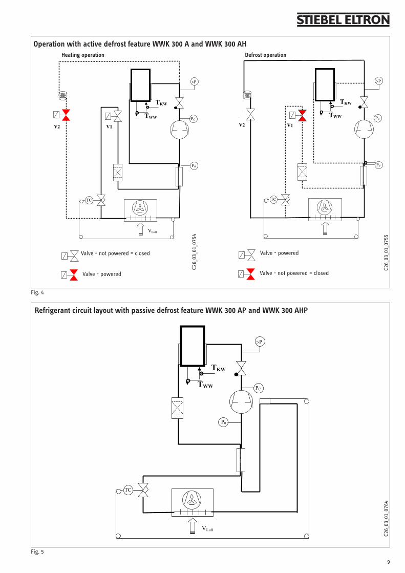
1.6 Operation with active defrost feature WWK 300 A and WWK 300 AH
Subject to the relative humidity and the DHW temperature, the evaporator begins to build up hoar frost at an ambient temperature of below 6 °C.
If the evaporator is covered in hoar frost, the frost monitor N2 (see wiring diagram Fig. 6 and 7) switches the fan OFF, whilst the compressor continues to run, and the changeover valve V2 routes the hot gas directly to the evaporator. For this, the condenser is shut off by changeover valve V1 (see Fig. 4) When the temperature at the evaporator fins rises above 3 °C, the fan is started again, and DHW heating continues.
The DHW heat pump can be operated at ambient temperatures as low as 0 °C. The evaporator is defrosted according to demand in the temperature range 0 °C to +6 °C. This extends the heat-up time.
Ambient temperature
!The heat pump must not be installed in areas where ambient
temperatures frequently exceed 42 °C or areas where temperatures frequently drop below 0 °C
1.7 Operation with passive defrost feature WWK 300 AP and WWK 300 AHP
The limit of application of the WWK AP / AHP (without hot gas defrost feature) is set to 6 °C.
However, with this limit of application, the evaporator may build up hoar frost subject to air temperature and relative humidity, particularly when the DHW temperature is low. The compressor will be switched OFF as soon as the evaporation temperature lies below - 7 °C for any length of time. When the temperature at the evaporator fins rises above 3 °C, the compressor are started again, and the DHW heating continues.
Ambient temperature
!The heat pump must not be installed in areas where ambient
temperatures frequently exceed 42 °C or areas where temperatures frequently drop below 6 °C
1.8 Maintenance and cleaningThe device is generally maintenance free, with the exception of cleaning the strainer in the condensate drain.
Sand and dust can result in sludge building up inside the strainer. Therefore, clean the strainer at least twice per annum or in accordance with demand.
A damp cloth is sufficient for cleaning all plastic parts. Never use scouring or solvent-based cleaning agents.
!Please note: Maintenance work, e.g. checking the electrical safety,
must only be carried out by a qualified contractor.
Check the condensate drain at least zmonthly at the bottom strainer outlet and at the top condensate pan drain (visual check, see Fig. 4, pos 16).
1. Operating instructions for users and contractors

4
Remove contaminants and blockages immediately.
For the WWK300 AH and WWK300 zAHP, it is recommended that the electric booster heater be descaled from time to time. this will result in prolonged life fo the electric booster.
Your local contractor, who is familiar zwith the local water quality, should identify for you the timing of the next service.
Ask your local contractor to regularly zcheck the safety assembly and the electric booster heater.
The device is subject to mains water zpressure. The expansion water drips from the safety valve during heat-up. Inform your local contractor of water drips from the system after the heat-up process has ended.
To protect the steel cylinder against zcorrosion, the interior is coated with a special enamel and is furthermore equipped with a protective anode. Ask your local contractor to check the protective anode regularly.
1.9 Troubleshooting by the user
No hot water
Should you fail to obtain hot water at any time, you can take the following steps to remedy that situation.
No electrical power Check the fuse/circuit breaker in your fuse box. If it has blown/tripped, replace/reset the fuse/MCB. If it should blow/trigger repeatedly, notify your local contractor.
Still no hot water, even though power is available Check, whether the air inlet/outlet is blocked.
The thermoswitch trips out or the high limit safety pressure limiter switches the compressor OFF if the compressor is overloaded due to excessive ambient temperature or excessive air temperature (>42 °C), or because of a fault in the refrigerant circuit. Ask your local contractor to remove the fault.
The thermoswitch automatically switches itself ON again.
!The high limit safety pressure limiter must only be reset by your
contractor after he has removed the cause of the relevant fault.
Other issues
Safety valve of the cold water supply line drips This may occur during the heat-up phase and is completely normal.
The condensate drain drips This always happens when the surface temperature of the evaporator is lower than the ambient dew point temperature.
For all other faults, consult your contractor.
5
2.1 Regulations and standards
The z installation (water and electrical work) and commissioning, as well as the maintenance of this equipment, must only be carried out by an authorised qualified contractor in accordance with these instructions.
Perfect function and safe operation zcan only be assured when using original accessories and spare parts intended for this equipment.
DIN VDE 0100 / DIN VDE 0701 z
Regulations of your local electricity zsupply utility.
DIN 1988 / DIN 4109 z
Regulations of your local water supply zutility.
Fig. 1
2. Installation instructions for contractors
The following standards were taken into account:
AS 4234, AS 3498, AS 4020, AS 1056.1
AS/NZS 2712, AS/NZS 3350.2.40/30/30.2
IEC 60335-1-2-40, IEC 61000-3-2; 1995
IEC 61000-3-3, IEC 55014-1 IEC 55014-2
EMC Directive 89/336/EEC
EN 255 T3
Also observe the following:
The equipment type plate z
The specification z
Water installation z
Observe the AS/NZS 3500. [local —regulations].
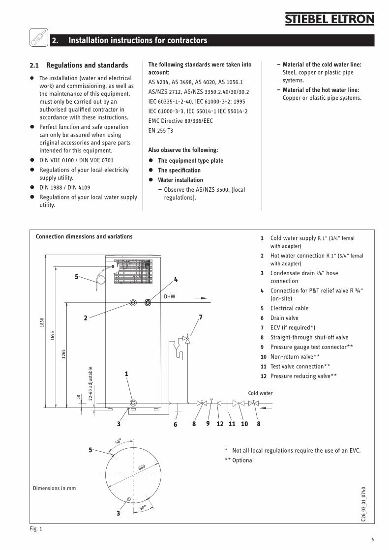
Cold water supply 1 R 1“ (3/4“ femal with adapter)
Hot water connection 2 R 1“ (3/4“ femal with adapter)
Condensate drain ¾“ hose 3 connection
Connection for P&T relief valve R ¾“ 4 (on-site)
Electrical cable5
Drain valve6
ECV (if required*)7
Straight-through shut-off valve8
Pressure gauge test connector**9
Non-return valve**10
Test valve connection**11
Pressure reducing valve** 12
12 10116 898
7
3
22-6
0 ad
just
able
1
2
Dimensions in mm
660
Connection dimensions and variations
5
DHW
Cold water
4
1695
1265
3
1830
5
30°
48°
C26_
03_0
1_07
40
Material of the cold water line: —Steel, copper or plastic pipe systems.
Material of the hot water line: — Copper or plastic pipe systems.
58
* Not all local regulations require the use of an EVC.
** Optional

6
min
.100
2.2 Installation
Transport
To protect the equipment against damage, it must be transported vertically inside its dedicated packaging. Where space is restricted, you may also move the equipment tipped backwards at an angle.
Positioning
Position the device in the installation —location.
i Note: Ensure that the casing panel in the lower area of
the device is not damaged during positioning.
Remove packing straps and —polystyrene mouldings.
Level the device by adjusting the —equipment feet.
After leveling the device fix the nut of —the rubber feet to provide a maximum of structural safety.
External installation
The location where the WWK is to be installed must meet the following conditions:
Load-bearing floor (wet weight of the —WWK approx. 430 kg).
Never operate the WWK in rooms at a —risk from explosion due to dust, gases or vapours.
It is prefferred that the location of —the unit is not near a bedroom or a neighbour´s bedroom. Ideally a unit may mounted near a kitchen or laundry. Opposite a neighbours gara-ge is always prefferred.
The water heater should be located —as close as possible to the most fre-quently used hot water tap connec-tion.
Ensure that the data plate is clearly —visible.
Internal installation
The room where the WWK is to be installed must meet the following conditions:
Load-bearing floor (wet weight of the —WWK approx. 430 kg).
Never operate the WWK in rooms at a —risk from explosion due to dust, gases or vapours.
Include in your considerations the —utilisation of waste heat, for example from a boiler, tumble drier or refrige-rator/freezer.
The available floor area in the instal- —lation room must be at least 6 m². Never install this equipment in rooms with a volume of less than 13 m³.
Never restrict the clearances of the —WWK through walls and ceilings fur-ther than illustrated in Fig. 2.
The room temperature must never fall —below 0 °C, as the ambient tempera-ture will be reduced by approx. 1-3 °C through the heat pump operation. The initial temperature is reached again approx. ½ h after the heat pump has been switched OFF.
When installing the heat pump in a boiler room, ensure that the boiler operation will not be impaired.
2.3 Water connection
Remove the protective caps from the —connectors.
With a sharp knife, cut a hole into the —protective caps and invert over the pipe to be connected.
Connect the pipe and refit the —protective caps.
!Please note: To protect against the risk of corrosion, make
the connection as flat packing seal. The use of hemp on connections is not acceptable.
Insulate the DHW line in accordance with local regulations.
Accurately maintain the order of fittings on the cold water side (see Fig. 1).
Air Air
Dimensions in mm
Flush the line prior to installation.
Install a drain valve at the lowest point of the cold water supply line.
Install a pressure reduction valve when the water pressure is higher than 500 kPa (5 bar).
Special measures are required at a water pressure in excess of 10 bar (see DIN 1988).
Expansion control valve (Fig. 1, pos. 7)
Observe the local requirements for an ECV (optional)
The diameter of the connecting pipe —must not be larger than the safety valve diameter.
Size the drain so that water can drain —off, even if the safety valve has been fully opened.The drain outlet must not be able to be —closed and must always remain open to atmosphere.
The safety valve must open at 475 kPa — .
P&T relief valve (Fig. 1, pos. 4)
Atsite: Install the provided P&T relief valve.The P&T relief valve must open at 600 kPa.
Condensate drain The device is designed so that, if it is installed externally, the condensate can freely drain away. However, the condensate can also (in case of internal installation) be routed into a drain in the floor or into a wall drain connection located at a higher point.
Fig. 2
PositioningC2
6_03
_01_
0739
7
If the condensate is to be routed through a higher wall outlet, position the heat pump on a plinth (see Fig. 2), and route a suitable drain hose on site.
i Note: Never kink the hose, to ensure the condensate drains
perfectly.
If required install a condensate pump (part no. see page 13).
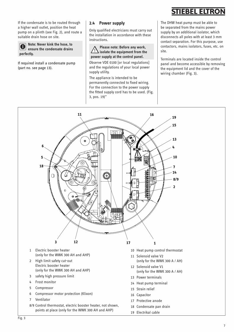
2.4 Power supply
Only qualified electricians must carry out the installation in accordance with these instructions.
!Please note: Before any work, isolate the equipment from the
power supply at the control panel.
Observe VDE 0100 [or local regulations] and the regulations of your local power supply utility.
The appliance is intended to be permanently connected to fixed wiring. For the connection to the power supply the fitted supply cord has to be used. (Fig. 3, pos. 19)”
The DHW heat pump must be able to be separated from the mains power supply by an additional isolator, which disconnects all poles with at least 3 mm contact separation. For this purpose, use contactors, mains isolators, fuses, etc. on site.
Terminals are located inside the control panel and become accessible by removing the equipment lid and the cover of the wiring chamber (Fig. 3).
Fig. 3
1 Electric booster heater (only for the WWK 300 AH and AHP)
2 High limit safety cut-out Electric booster heater (only for the WWK 300 AH and AHP)
3 safety high pressure limit
4 Frost monitor
5 Compressor
6 Compressor motor protection (Klixon)
7 Ventilator
8/9 Control thermostat, electric booster heater, not shown, points at place (only for the WWK 300 AH and AHP)
1
2
13
10
15
1611
6
5
3 12 17
14718
8/9
4
10 Heat pump control thermostat
11 Solenoid valve V2 (only for the WWK 300 A / AH)
12 Solenoid valve V1 (only for the WWK 300 A / AH)
13 Power terminals
14 Heat pump terminal
15 Strain relief
16 Capacitor
17 Protective anode
18 Condensate pan drain
19 Electrikal cable
19
8
2.5 Commissioning
Only approved contractors may commission this equipment and instruct the owner in its use.
Commissioning
Fill, vent and thoroughly flush the —device.
Check the safety assembly. —Inform the user that water may drip from the safety valve whilst the water is being heated up.
Switch ON the power supply —
Note:
Never operate the equipment outside —the temperature range 0 °C to + 42 °C.
At temperatures below - 15 °C (e.g. transport/storage), the safety temperature cut-out may respond. Press the reset button after the temperature is much higher than
-15 °C (Fig. 3, pos. 3).
2.6 Safety equipment and maintenance
Only qualified contractors must carry out the installation in accordance with these instructions.
On the equipment
In case of a fault, the safety equipment of the WWK 300 interrupts the relevant power circuit.
!Please note: Before any work on the equipment, disconnect all
poles from the mains.
High limit safety cut-out (STB) electric booster heater Equipment with electric booster heater is stopped if the DHW temperature exceeds 95 °C.
When the source of the fault has been removed, reset the high limit safety cut-out by pressing the reset button (pos 2, Fig. 3). The heat pump top cover should be opened for access to this device as shown in fig. 3.
Safety high pressure limiter (SDBK) Fig 3 The safety high pressure limiter shuts down the compressor, if the pressure inside the refrigerant circuit exceeds the permissible maximum value. The safety high pressure limiter may also respond, if the WWK 300 is operated above its permissible limit (>42 °C air temperature)
or the control thermostat of the heat pump fails to respond. Reset the high pressure limit safety cut-out by pressing the reset button (pos 3, Fig. 3), after the cause of the fault has been removed.
Protective motor thermoswitch The protective motor switch will shut down the compressor, if it is overloaded because of excessive thermal load. Remove the relevant fault. The protective motor switch restarts the compressor automatically after 5 - 15 seconds.
Protective anode An anode for the protection of the DHW cylinder is inserted right in the center of the heat pump cylinder (item 17, fig.3). Replace the anode with a new one if the installed one has been consumed. When installing the anode, ensure that the metallic conductor connection is correctly made. It’s recommended for first anode inspection to happen after 2 years after installation. Unless in areas where total dissolved solids exceeds 400 mg/L the magnesium alloy anode should be replaced with an aluminium anode. Inspections should be more frequent. Your contractor, who will be familiar with your water quality, will advise you of the optimum timing for inspection thereafter. Should it be impossible to insert a rod anode, part no. 143496 from above, you may have a sectional anode installed instead.
Cleaning the evaporator Maintaining the full output of the WWK 300 requires an occasional professional cleaning of the evaporator. Clean the evaporator only with water and a brush. Never use acidic or alkaline cleaning solutions.
Further information regarding the equipment:
Cleaning and descaling zAfter removing the plug or the electric booster heater (if installed), clean the cylinder through the inspection aperture. Use a descaling pump to descale the cylinder. Connect the pump between the cold water connection and the inspection aperture. Ensure that the protective anode is removed prior to descaling. When installing the anode, ensure that the metallic conductor connection is correctly made.
z Draining the cylinder:Close the shut-off valve in the cold —water supply.Fully open the hot taps at all draw- —off points.The cylinder is drained via the cold —water inlet line. Residual water remains in the lower part of the cylinder.
i Note: Hot water can be expelled during draining.
On the system
Safety valve (on-site) This valve opens when the water pressure exceeds the preset value of 600 kPa (6 bar) thereby relieving the pressure. It is adjusted so that no water will be expelled when heating is switched OFF. Should it continue to drip excessively, either the valve seat has become contaminated, the water pressure is too high or the pressure reducing valve has become faulty.
Pressure reducing valve (on-site provision) Check the valve for perfect function. Replace it, if required.
Regular valve maintenance Safety requires that valves are regularly checked for perfect function. For this, regularly vent the safety valve until a full stream of water flows from it. Close the safety valve after checking.
How quickly limescale builds up depends on the local water quality.
As your local contractor is familiar with your local water quality, let him determine the timing of this check.
Glenn65
Note
1 year
9
WWK 300 E Kältekreis Schemata
Heizbetrieb
Ventil bestromt
Ventil stromlos = geschlossen
PC
P0
>P
TC
VLuft
TKW
TWW
V2 V1
Abtaubetrieb
V2
Ventil bestromt
Ventil stromlos = geschlossen
PC
P0
>P
TC
TKW
TWW
V1
Operation with active defrost feature WWK 300 A and WWK 300 AHHeating operation Defrost operation
C26_
03_0
1_07
55
C26_
03_0
1_07
54
Fig. 4
Refrigerant circuit layout with passive defrost feature WWK 300 AP and WWK 300 AHP
Fig. 5
Valve - powered
Valve - poweredValve - not powered = closed
Valve - not powered = closed
WWK 300 AP Kältekreis Schemata
PC
P
TC
VLuft
TKW
TWW
P0
C26_
03_0
1_07
64
10
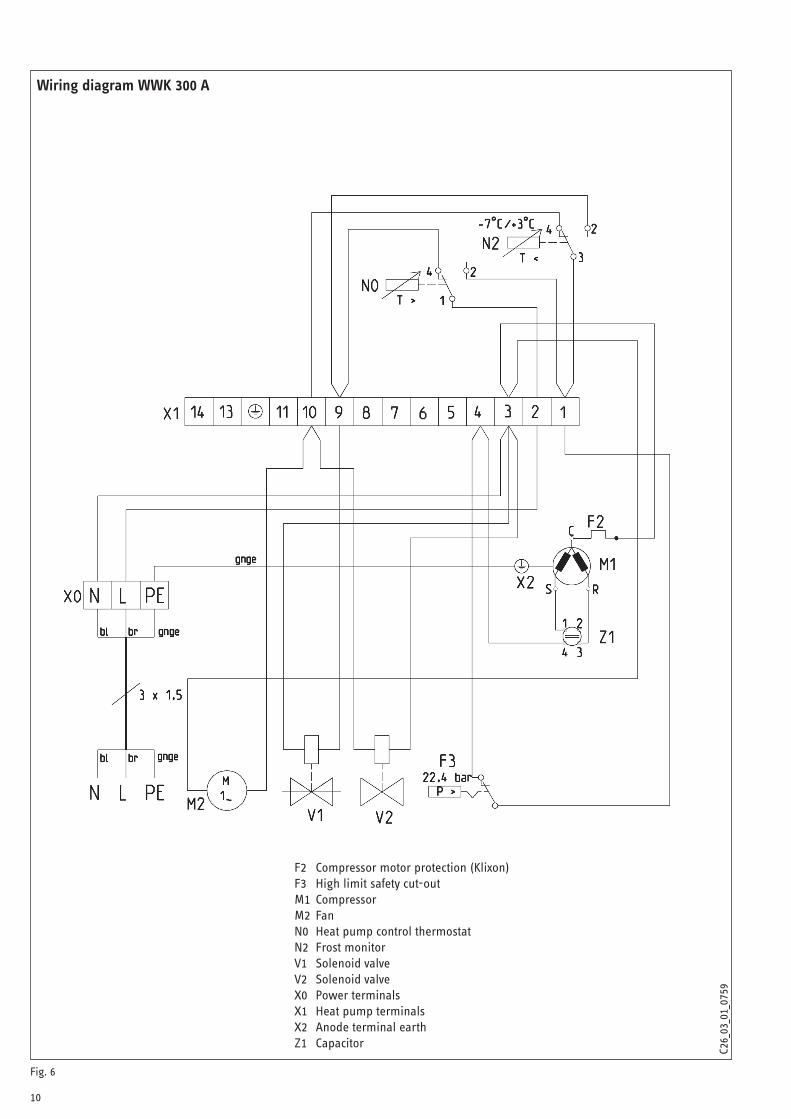
Fig. 6
Wiring diagram WWK 300 A
F2 Compressor motor protection (Klixon)F3 High limit safety cut-outM1 CompressorM2 Fan N0 Heat pump control thermostatN2 Frost monitorV1 Solenoid valveV2 Solenoid valveX0 Power terminalsX1 Heat pump terminalsX2 Anode terminal earthZ1 Capacitor
C26_
03_0
1_07
5928
0888
-347
27

11
Fig. 7
Wiring diagram WWK 300 AP
F2 Compressor motor protection (Klixon)F3 High limit safety cut-outM1 CompressorM2 Fan N0 Heat pump control thermostatN2 Frost monitorX0 Power terminalsX1 Heat pump terminalsX2 Anode terminal earthZ1 Capacitor
C26_
03_0
1_09
1828
4101
-347
27
12
C26_
03_0
1_07
60
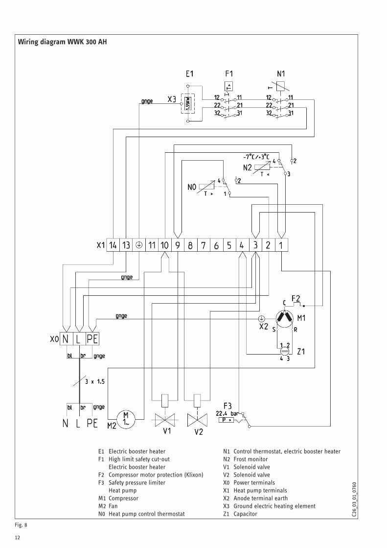
Wiring diagram WWK 300 AH
E1 Electric booster heater F1 High limit safety cut-out
Electric booster heaterF2 Compressor motor protection (Klixon)F3 Safety pressure limiter
Heat pumpM1 CompressorM2 Fan N0 Heat pump control thermostat
N1 Control thermostat, electric booster heaterN2 Frost monitorV1 Solenoid valveV2 Solenoid valveX0 Power terminalsX1 Heat pump terminalsX2 Anode terminal earthX3 Ground electric heating elementZ1 Capacitor
Fig. 8
2829
87-3
4727
13
C26_
03_0
1_09
19
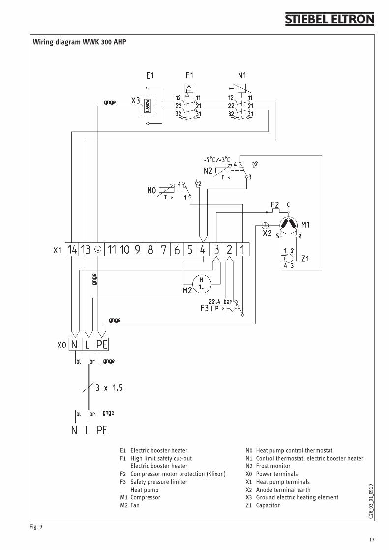
Wiring diagram WWK 300 AHP
E1 Electric booster heater F1 High limit safety cut-out
Electric booster heaterF2 Compressor motor protection (Klixon)F3 Safety pressure limiter
Heat pumpM1 CompressorM2 Fan
N0 Heat pump control thermostatN1 Control thermostat, electric booster heaterN2 Frost monitorX0 Power terminalsX1 Heat pump terminalsX2 Anode terminal earthX3 Ground electric heating elementZ1 Capacitor
Fig. 9
2829
88-3
4727

14
1) Cold water mains pressure must be limited to 500 kPa. Required P&T relief valve must open at 600 kPa.2) Tamb = 42°C Twater = 60°C / 240V3) Test point to DIN 8947 at 15 °C air temperature, 70 % rel. humidity and 45 °C water temperature.4) Test point at 15 °C air temperature, 70 % rel. humidity, heating up water from 15 °C to 60 °C (according to EN 255 T3)
Type WWK 300 A WWK 300 AP WWK 300 AH WWK 300 AHP
Part no. 222422 227069 227070 227071
Version with active defrost with passive defrost with active defrost and booster heater
with passive defrost and booster heater
Application limits for heat pump operation °C 0 to + 42 6 to + 42 0 to + 42 + 6 to + 42
DHW temperature Heat pumpHeating element
°C°C
+ 60 + 60 + 60+ 60
+ 60+ 60
Air flow rate m3/h 550 550 550 550
Cylinder capacity l 303 303 303 303
Refrigerant / filling weight -- / g R 134a / 900 R 134a / 900 R 134a / 900 R 134a / 900
Dimensions H /Ø mm 1875 / 660 1875 / 660 1875 / 660 1875 / 660
Height of unit when tilted mm 1990 1990 1990 1990
Height of unit when tilted including packing mm 2285 2285 2285 2285
Weight dry/wet kg 125 / 428 125 / 428 130 / 432 130 / 432
Water connection inch R 1“ (3/4“ femal with adapter)
R 1“ (3/4“ femal with adapter)
R 1“ (3/4“ femal with adapter)
R 1“ (3/4“ femal with adapter)
Condensate connection Inch 3/4“ 3/4“ 3/4“ 3/4“
Condenser Safety heat exchanger (tank wrap-around condenser)
Maximum operating pressure, water side 1) kPa 600 600 600 600
Maximum positive pressure, refrigerant side MPa 2.4 2.4 2.4 2.4
Electrical specification
Voltage / Frequency V / Hz 1/N/PE ~ 240 / 50
Protection IP 24 IP 24 IP 24 IP 24
Maximum power consumption 2) kW 0.7 0.7 2,25 2,25
Electrical protection A 10 gL 10 gL 10 gL 10 gL
Rated current HP A 2.5 2.5 2.5 2.5
Rated power consumption HP 3) kW 0.5 0.5 0.5 0.5
Power consumption, booster heater kW 1.690 1.690
Heating output HP 4) kW approx. 1.7 approx. 1.7 approx. 1.7 approx. 1.7
COP (t) 4) 3.19 3.3 3.19 3.3
2.7 Specification

15
WARRANTY
For guarantees please refer to the respective terms and conditions of supply for your country.
The installation, electrical connection and first operation of this appli-ance should be carried out by a qualified installer.
The company does not accept liability for failure of any goods supplied which have not been installed and operated inaccor-
dance with the manufacturer‘s instructions.
WARRANTY - Australia only
Stiebel Eltron (Aust) Pty Ltd warrants the domestic range of heat pump water heaters (WWK300 and WWK300 A) to be free from defects in mate-rial and workmanship under normal use and service in accordance with the following terms:
1. Repair or if necessary replace the water heater, or
2. Replace any component which falls within the warranty period as specified below (subject to the conditions and exclusions thereafter referred to)
5 years for the cylinder and condenser
2 years for the sealed refrigeration system, including compres-sor, evaporator, valves and associated pipe work.
1 year for all other componentry (electrical)
The above shall not apply to such water heaters or part thereof which, in our opinion, have been subject to any accident, alteration, abuse or misuse or have suffered any damage by flood, fire or act of God, or if any repairs have been made or attempted to be made by any person or persons not approved by us. The warranties shall not extend to any loss suffered by, or resulting from, the non-operation of the water heater or part thereof.
We will not incur any obligation or liability whatsoever under the war-ranties for any damage or harm which may arise directly or indirectly as a result of the water heater being installed by other than registered qualified plumbers or being connected to a water or power supply not in accordance with the regulations of the relevant electric, water and health authorities.
The following items 1-5 are specifically excluded from the normal terms of warranty.
1. Damage as the result of transportation, removal, or storage.
2. Damage due to connection to incorrect water supply, incorrect in-stallation or faulty valve.
3. Damage or faulty operation due to foreign matter in the water sup-ply.
4. Damage or faulty operation due to the corrosive elements in the water supply and proper precautions not having been followed (eg, anode inspection & change). Void of warranty can be even if anode is changed with high minerals in the water or total dissolved sol-ids exceeds 400 mg/L. Warranty void with use with bore, dams or swimming pool water.
5. Damage or faulty operation due to incorrect installation where the air flow, to and/or from the unit, is restricted or impeded
Not withstanding anything contained herein, the units shall continue to be subject to any implied warranty provided by the Trade Practices Act 1974 (as amended) if and to the extent that the said Act is applicable and prevents the exclusion, restriction or modification of that warranty.
This free service will apply, in principle, to metropolitan and other ac-cessible areas. If the unit is located in a remote area an extra service charge may be applicable due to travel.
Service costs by others are not covered by the Warranty and are at the user's expense. In the event of any claim being made under the war-ranty, it is the original purchaser's responsibility to provide evidence of purchase and date of purchase.
A nominal service charge may be made should the appliance be found to be in normal working condition and the problem located elsewhere.
STIEBEL ELTRON (AUST) PTY LTD
Unit 4, 109 Riverside Place
Morningside Q 4170
PH: 1800 153 351 - Fax: 07 3399 3344
ENVIRONMENT AND RECYCLING
Please help us to protect the environment by disposing of the packaging in accordance with the national regulations for waste processing.
New Zealand
PAREX INDUSTRIES LTD5 Tolich PlaceHendersonAucklandTel: 09 836 6566, Fax: 09 836 6033www.parex.co.nz
15
WARRANTY
For guarantees please refer to the respective terms and conditions of supply for your country.
The installation, electrical connection and first operation of this appli-ance should be carried out by a qualified installer.
The company does not accept liability for failure of any goods supplied which have not been installed and operated inaccor-
dance with the manufacturer‘s instructions.
WARRANTY - Australia only
Stiebel Eltron (Aust) Pty Ltd warrants the domestic range of heat pump water heaters (WWK300 and WWK300 A) to be free from defects in mate-rial and workmanship under normal use and service in accordance with the following terms:
1. Repair or if necessary replace the water heater, or
2. Replace any component which falls within the warranty period as specified below (subject to the conditions and exclusions thereafter referred to)
5 years for the cylinder and condenser
2 years for the sealed refrigeration system, including compres-sor, evaporator, valves and associated pipe work.
1 year for all other componentry (electrical)
The above shall not apply to such water heaters or part thereof which, in our opinion, have been subject to any accident, alteration, abuse or misuse or have suffered any damage by flood, fire or act of God, or if any repairs have been made or attempted to be made by any person or persons not approved by us. The warranties shall not extend to any loss suffered by, or resulting from, the non-operation of the water heater or part thereof.
We will not incur any obligation or liability whatsoever under the war-ranties for any damage or harm which may arise directly or indirectly as a result of the water heater being installed by other than registered qualified plumbers or being connected to a water or power supply not in accordance with the regulations of the relevant electric, water and health authorities.
The following items 1-5 are specifically excluded from the normal terms of warranty.
1. Damage as the result of transportation, removal, or storage.
2. Damage due to connection to incorrect water supply, incorrect in-stallation or faulty valve.
3. Damage or faulty operation due to foreign matter in the water sup-ply.
4. Damage or faulty operation due to the corrosive elements in the water supply and proper precautions not having been followed (eg, anode inspection & change). Void of warranty can be even if anode is changed with high minerals in the water or total dissolved sol-ids exceeds 400 mg/L. Warranty void with use with bore, dams or swimming pool water.
5. Damage or faulty operation due to incorrect installation where the air flow, to and/or from the unit, is restricted or impeded
Not withstanding anything contained herein, the units shall continue to be subject to any implied warranty provided by the Trade Practices Act 1974 (as amended) if and to the extent that the said Act is applicable and prevents the exclusion, restriction or modification of that warranty.
This free service will apply, in principle, to metropolitan and other ac-cessible areas. If the unit is located in a remote area an extra service charge may be applicable due to travel.
Service costs by others are not covered by the Warranty and are at the user's expense. In the event of any claim being made under the war-ranty, it is the original purchaser's responsibility to provide evidence of purchase and date of purchase.
A nominal service charge may be made should the appliance be found to be in normal working condition and the problem located elsewhere.
STIEBEL ELTRON (AUST) PTY LTD
Unit 4, 109 Riverside Place
Morningside Q 4170
PH: 1800 153 351 - Fax: 07 3399 3344
ENVIRONMENT AND RECYCLING
Please help us to protect the environment by disposing of the packaging in accordance with the national regulations for waste processing.

ВозмоҖность неточностейи технических изменений не исключается.
CAP
2800
10/3
4890
/835
5
Australia STIEBEL ELTRON Australia Pty.Ltd.Unit 4/109 Riverside Place, Morningside, QLD, 4170Tel. 1800 153 351 | Fax 07 3399 3344Email [email protected] www.stiebel.com.au
PAREX INDUSTRIES LTD5 Tolich PlaceHendersonAucklandTel: 09 836 6566, Fax: 09 836 6033www.parex.co.nz