Opening ANSYS Workbench - Miami University Files/ANSYS_Tutorial.pdf · Opening ANSYS Workbench...
48
Transcript of Opening ANSYS Workbench - Miami University Files/ANSYS_Tutorial.pdf · Opening ANSYS Workbench...


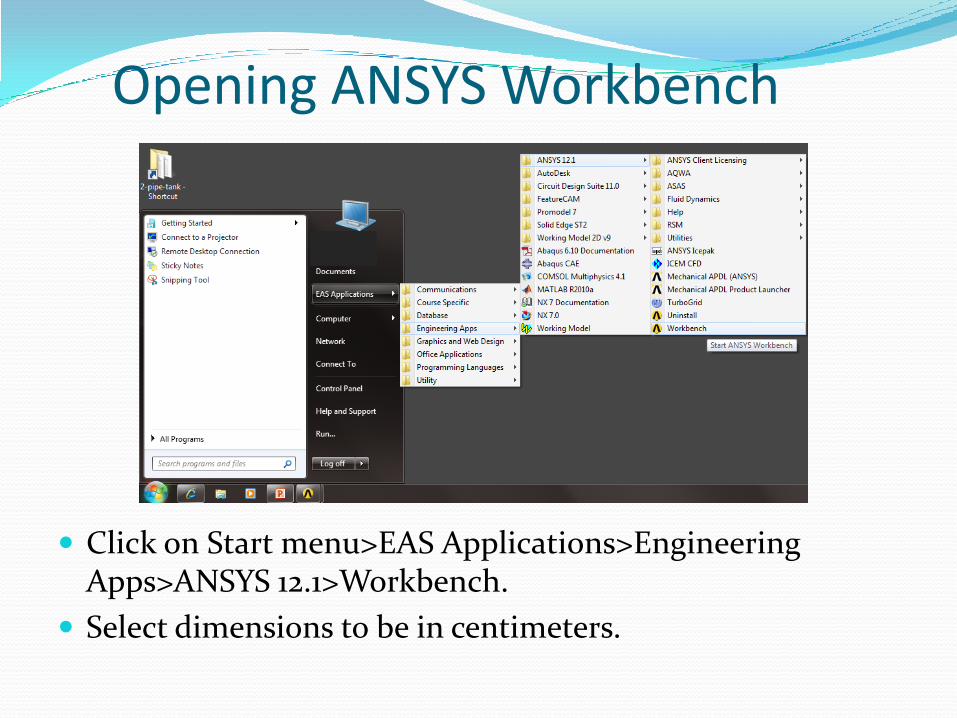
Opening ANSYS Workbench
Click on Start menu>EAS Applications>Engineering Apps>ANSYS 12.1>Workbench.
Select dimensions to be in centimeters.
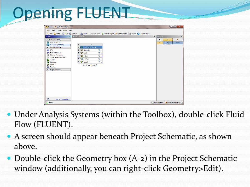
Opening FLUENT
Under Analysis Systems (within the Toolbox), double-click Fluid Flow (FLUENT).
A screen should appear beneath Project Schematic, as shown above.
Double-click the Geometry box (A-2) in the Project Schematic window (additionally, you can right-click Geometry>Edit).

Creating Geometry
This will open FLUENT- Design Modeler.
In the Tree Outline to the left of the screen, double-click the plane that you will be sketching on (for this example, we will be using the X-Y plane).

Creating Geometry
Click on the New Sketch icon (shown by the red arrow).
This should insert ‘Sketch 1’ below the XYPlane in the Tree Outline.
New Sketch
Creating Geometry
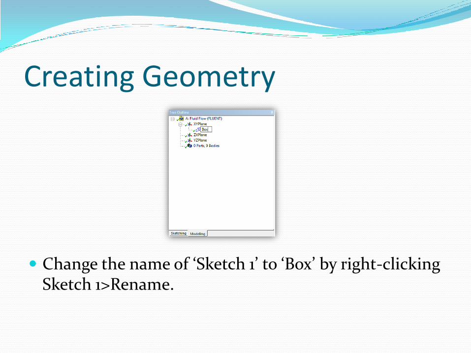
Change the name of ‘Sketch 1’ to ‘Box’ by right-clicking Sketch 1>Rename.
Creating Geometry
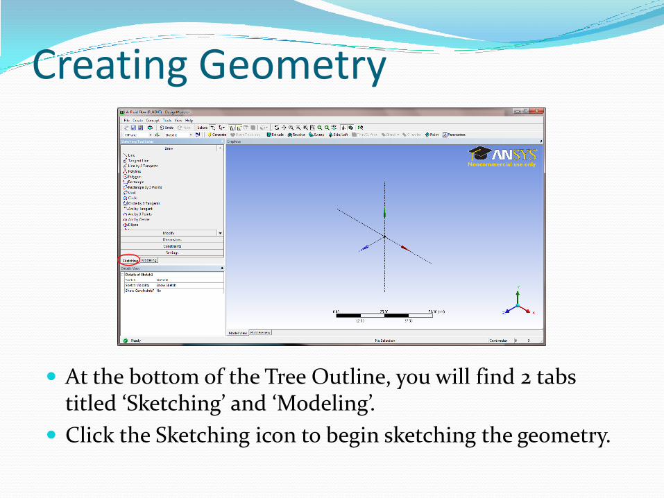
At the bottom of the Tree Outline, you will find 2 tabs titled ‘Sketching’ and ‘Modeling’.
Click the Sketching icon to begin sketching the geometry.

Creating Geometry
Click the Rectangle icon under the Sketching Toolbox.
In the bottom-left side of the screen, instructions for using the rectangle tool will be displayed.
Click anywhere on the x-axis and create a rectangle.
Dimensioning
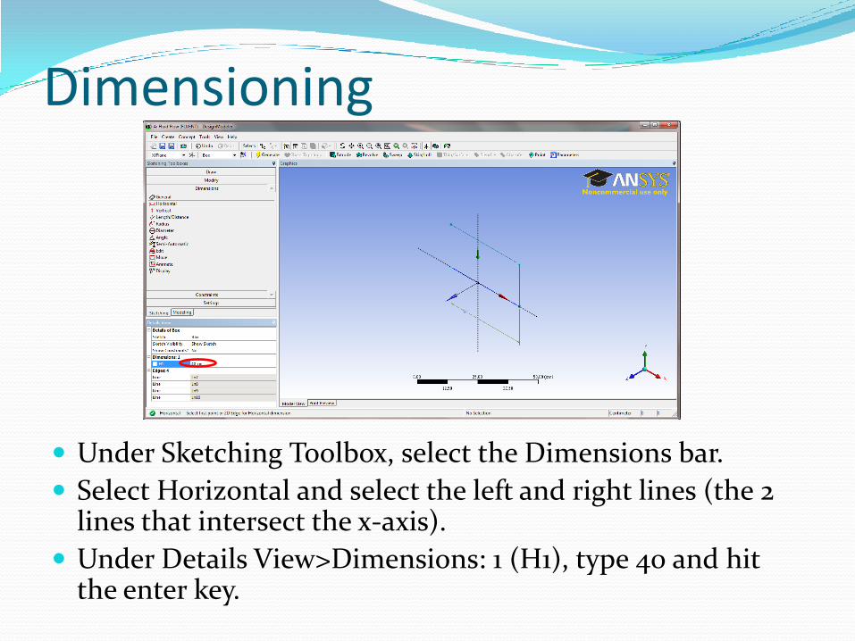
Under Sketching Toolbox, select the Dimensions bar.
Select Horizontal and select the left and right lines (the 2 lines that intersect the x-axis).
Under Details View>Dimensions: 1 (H1), type 40 and hit the enter key.

Dimensioning
Select Vertical under Dimensions and select the top and bottom lines (the lines running parallel to the x-axis).
Under Details View>Dimensions: 2 (V2), type 20 and hit the enter key.

Dimensioning
Select Length/Distance under Dimensions and select the right, vertical line and the y-axis.
Under Details View>Dimensions: 3 (L3), type 20 and hit the enter key.
The box should now lie on the x-axis and be symmetric about the y-axis.

Extruding
Select the Extrude icon at the top.
Under Details View>FD1, Depth, type 20 and hit the enter key.
Select the Generate icon at the top.
ExtrudeGenerate
Extruding
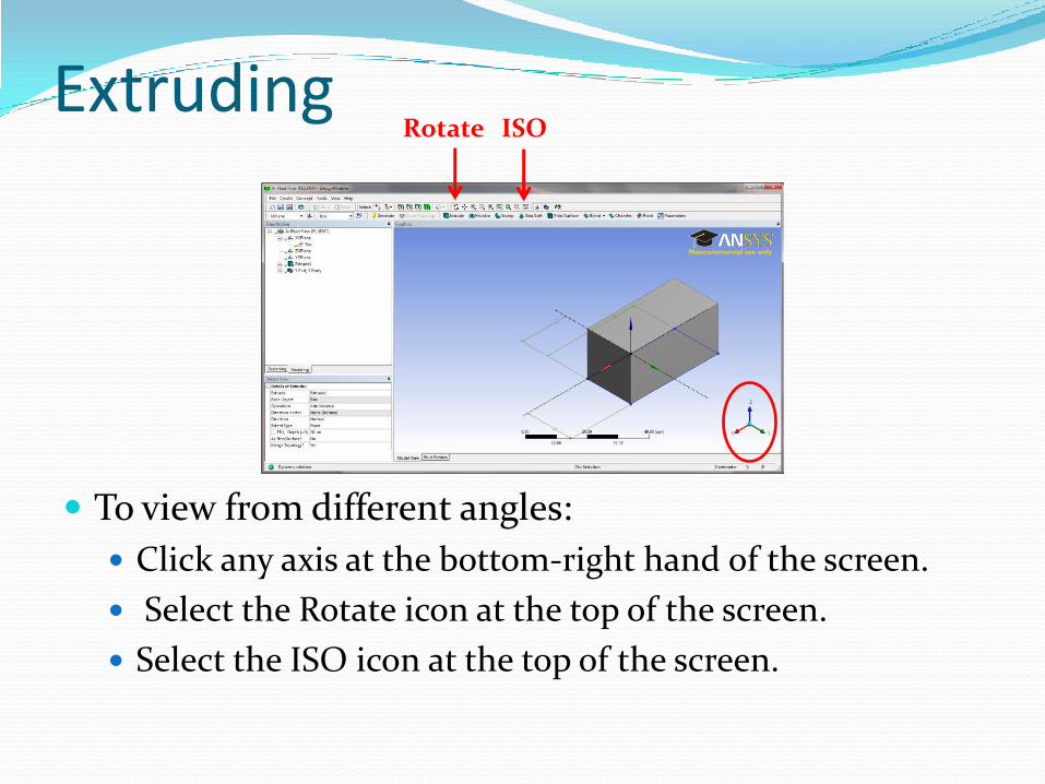
To view from different angles:
Click any axis at the bottom-right hand of the screen.
Select the Rotate icon at the top of the screen.
Select the ISO icon at the top of the screen.
ISORotate

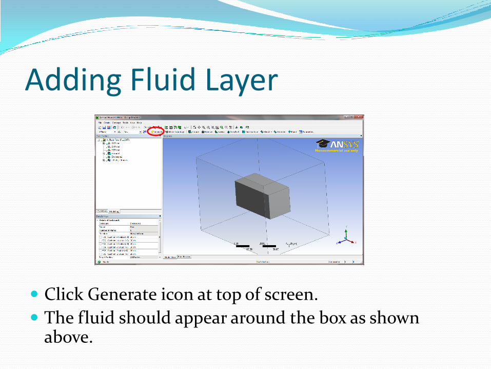
Adding Fluid Layer
Click Tools>Enclosure.

Adding Fluid Layer
Under Details of Enclosure, change all FD values to 20 cm.
Adding Fluid Layer
Click Generate icon at top of screen.
The fluid should appear around the box as shown above.

Saving Project
Click File>Save Project.
Save project as Box.wbpj.
Close out of Design Modeler window.

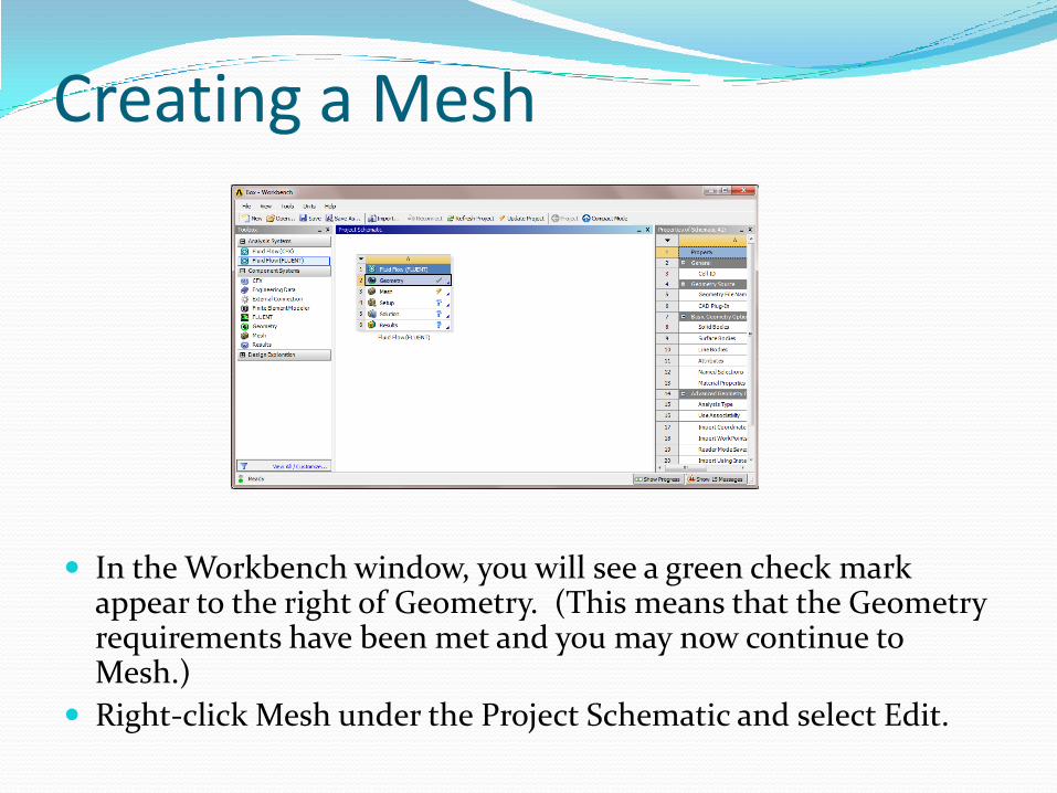
Creating a Mesh
In the Workbench window, you will see a green check mark appear to the right of Geometry. (This means that the Geometry requirements have been met and you may now continue to Mesh.)
Right-click Mesh under the Project Schematic and select Edit.

Creating a Mesh
The image should appear as shown above.
Under Model, double-click Geometry.
Under Geometry, 2 Solids should be listed.
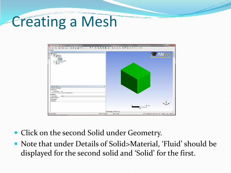
Creating a Mesh
Click on the second Solid under Geometry.
Note that under Details of Solid>Material, ‘Fluid’ should be displayed for the second solid and ‘Solid’ for the first.

Creating a Mesh
Right-click the first Solid under Geometry and click Rename.
Rename this as ‘Solid Box’.
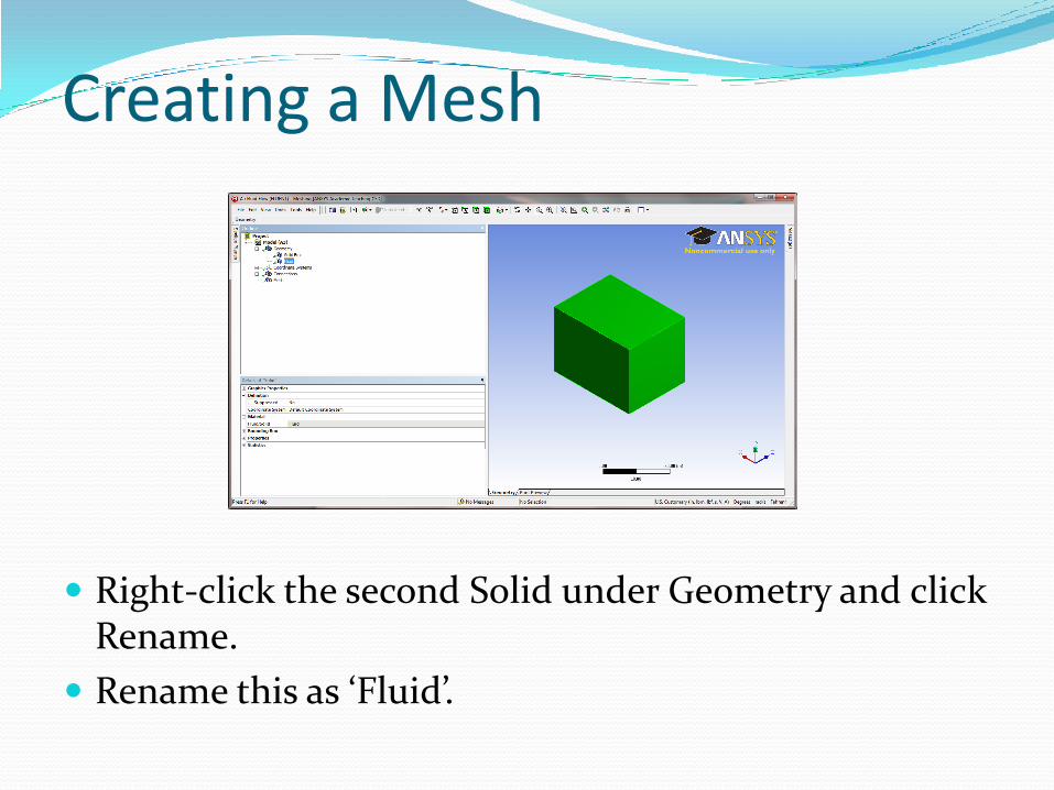
Creating a Mesh
Right-click the second Solid under Geometry and click Rename.
Rename this as ‘Fluid’.

Creating a Mesh
Right-click Solid Box and select Suppress Body.

Creating a Mesh
Under Outline, click Model (A3).
Under Details of Model, select Color and change to hot pink.

Creating a Mesh
To the left, under Details of Model>Lighting>Ambient, change the value of Ambient to 1 and press the Enter key.
Creating a Mesh
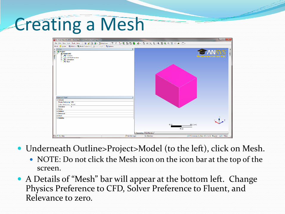
Underneath Outline>Project>Model (to the left), click on Mesh. NOTE: Do not click the Mesh icon on the icon bar at the top of the
screen.
A Details of “Mesh” bar will appear at the bottom left. Change Physics Preference to CFD, Solver Preference to Fluent, and Relevance to zero.

Creating a Mesh
Now select the Mesh icon on the icon bar at the top of the screen.
Select Generate Mesh.

Creating a Mesh
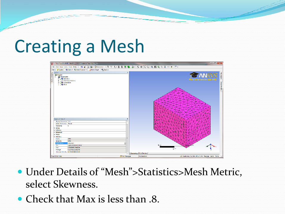
The mesh should appear as shown above.
Creating a Mesh
Under Details of “Mesh”>Statistics>Mesh Metric, select Skewness.
Check that Max is less than .8.

Creating a Mesh
Click the front face of the box to highlight it.
Now, right-click the face and scroll to Create Named Selection.
Name this face ‘inlet’.

Creating a Mesh
Rotate the box so that the parallel, unselected face is in front
Click the front face of the box to highlight it.
Now, right-click the face and scroll to Create Named Selection.
Name this face ‘outlet’.

Creating a Mesh
Click ISO for isometric view.
Click File>Save Project.
Close out of Meshing window.


Setup
Workbench window should now have a green check mark next to the Mesh bar (under Project Schematic).
If there is a yellow lightning bolt, click the Update Project icon at the top.

Setup
Right-click Setup, and select Edit.
When the FLUENT Launcher window pops up, select OK.

Setup
Under Problem Setup>Materials, check that Fluid is set to air and solid is aluminum.

Setup
Under Problem Setup>Boundary Conditions, check that inlet is set to Type: velocity-inlet and that outlet is set to Type: pressure-outlet.
Click Boundary Conditions>inlet>Edit.

Setup
Enter 20 (m/s) for Velocity Magnitude.
Change Specification Method to Intensity and Length Scale, Turbulent Intensity to 10 (%) and Turbulent Length Scale to .01 (m).
Click OK.

Setup
Click Boundary Conditions>outlet>Edit and enter 0 (Pascal) for Gauge Pressure.
Change Specification Method to Intensity and Length Scale, Backflow Turbulent Intensity to 10 (%) and Backflow Turbulent Length Scale to .01 (m).
Click OK.


Solution
Under Solution>Monitors, double-click Drag. Click Print to Console and Plot boxes and select wall-solid
under Wall Zones. Click OK.

Solution
Under Solution>Monitors, double-click Lift.
Click Print to Console and Plot boxes and select wall-solid under Wall Zones.
Click OK.

Solution
Under Solution>Solution Initialization change Compute From to wall-solid.
Click Initialize.

Solution
Under Solution>Calculation Activities, change Autosave Every (Iterations) to 5.

Solution
Under Solution>Run Calculation, change Number of Iterations to 100.
Click Calculate.

Solution
To view drag results, click the dropdown bar above the graph and select Drag Convergence History.