OpenGL in Jitter
19
OpenGL in Jitter Peter Elsea 3/3/10 1 OpenGL in Jitter Background OpenGL is a protocol for writing three dimensional object modeling code. Nearly all of the major animation programs use it, and the video graphic cards in most computers support it in hardware, so openGL scenes can be rendered with blazing speed. OpenGL is at the heart of modern computer games. The concept of openGL is very simple. A point is defined by three values describing its location in 3 dimensional space. This space has the origin at the center [0, 0, 0], with the X axis extending to the right, the Y axis pointing up, and the Z axis coming out of the screen. The dimensions are in floating point units, usually with a X of 1.0 [1, 0, 0] at the right edge of visibility. (Actually, what is visible depends on the point of view, which can be changed with various camera commands, explained later.) A group of three values is also often used to define a vector. A vector determines distance and direction. It is interpreted as an arrow from [0,0,0] to [X.Y,Z]. • The length of a vector is sqrt(X^2 + Y^2 + Z^2). • Vectors are added by adding up the X, Y, and Z components. • We often scale vectors by multiplying each component by the same value. • It is possible to multiply vectors, but we shouldn't need to. Vectors are used in many ways- for instance, when we want to define an orientation (up, tilt, whatever) a vector is generally used. Often we speak of a "unit vector" which is a vector of length one. Shapes. Shapes are specified as a series of points called vertices. Vertices can be connected by lines. Variations are line_strip and line_loop. Three vertices define a triangle. The vertices should be listed in counterclockwise order 1 . (Otherwise you are looking at the back) • Triangle_strips and triangle_fans are connected groups of triangles. • Four vertices define a quad. Again, counterclockwise order. • A quad_strip joins several quads. • Simple polygons can be defined by a list of vertices. 1 This is the "right hand rule". If the fingers on your right had curl in the direction of the vertices, your thumb points to the front.
-
Upload
jcpsimmons -
Category
Documents
-
view
167 -
download
10
description
OpenGlJitterMaxmsp
Transcript of OpenGL in Jitter

OpenGL in Jitter
Peter Elsea 3/3/10 1
OpenGL in Jitter
BackgroundOpenGL is a protocol for writing three dimensional object modeling code. Nearly all ofthe major animation programs use it, and the video graphic cards in most computerssupport it in hardware, so openGL scenes can be rendered with blazing speed. OpenGL isat the heart of modern computer games.
The concept of openGL is very simple. A point is defined by three values describing itslocation in 3 dimensional space. This space has the origin at the center [0, 0, 0], with theX axis extending to the right, the Y axis pointing up, and the Z axis coming out of thescreen. The dimensions are in floating point units, usually with a X of 1.0 [1, 0, 0] at theright edge of visibility. (Actually, what is visible depends on the point of view, which canbe changed with various camera commands, explained later.)
A group of three values is also often used to define a vector. A vector determines distanceand direction. It is interpreted as an arrow from [0,0,0] to [X.Y,Z].
• The length of a vector is sqrt(X^2 + Y^2 + Z^2).• Vectors are added by adding up the X, Y, and Z components.• We often scale vectors by multiplying each component by the same value.• It is possible to multiply vectors, but we shouldn't need to.
Vectors are used in many ways- for instance, when we want to define an orientation (up,tilt, whatever) a vector is generally used. Often we speak of a "unit vector" which is avector of length one.
Shapes.Shapes are specified as a series of points called vertices.Vertices can be connected by lines. Variations are line_strip and line_loop.Three vertices define a triangle. The vertices should be listed in counterclockwiseorder1. (Otherwise you are looking at the back)
• Triangle_strips and triangle_fans are connected groups of triangles.• Four vertices define a quad. Again, counterclockwise order.• A quad_strip joins several quads.• Simple polygons can be defined by a list of vertices.
1 This is the "right hand rule". If the fingers on your right had curl in the direction of thevertices, your thumb points to the front.

OpenGL in Jitter
Peter Elsea 3/3/10 2
Figure 1. Geometric Primitives (from the OpenGL redbook. Note the vertex order iswrong!)
These primitives can be combined to become facets or faces of 3 dimensional objects. Ifthe faces are small, the object may appear smoothly curved. Building objects fromvertices is amazingly tedious, so we usually leave the details to a modeling program likeMaya ($1000), TurboCad ($500) or Wings3d (free). Jitter also has many features tosimplify the work.
Every object has its own origin. When you position an object in openGL space, youspecify the location of its origin. The shape also has axes for rotation. These run throughthe origin with Z coming out the top.
Not all of the faces of a three dimensional object will be visible. The program can savetime by not drawing them, a process known as culling.
Colors and lightingShapes have a set of characteristics called material properties. These are mostly color,which is defined by RGBA values (note the different order from quicktime colors). Theseare specified according to the kind of light involved, and only make sense with someunderstanding of the general lighting scheme.
OpenGL in Jitter
Peter Elsea 3/3/10 3
The lighting in openGL includes ambient light and light from specific sources. (Jitteronly includes one specific source.) Lighting parameters are specified both for lightsources and the way objects reflect light. They can all have different colors:
• Ambient. Light from everywhere, like the blue of the sky.• Diffuse. Light from a specific source that scatters on reflection (as from a rough
surface).• Specular. Light from a specific source that reflects in a narrow band. (An object's
shininess parameter affects how tight this reflection is.)• Emissive. Objects can glow from within.
The material colors interact with the source colors in a realistic manner, so a red object inblue light looks black. An object's orientation with the light source generates someshadowing. In general the shadows take on the ambient color and the highlights arediffuse and specular. These shadows are calculated using vertex properties callednormals, which conceptually stick out of flat surfaces. Normals are another reason we usesoftware to design shapes.
The light reflected from an object is diminished if the object is far away. This effect isknown as fog. Fog has a color, which reduces light components.
Complex colors are applied as textures, which essentially print an image on the object.
Using OpenGL in JitterThe jitter openGL objects are prefaced with jit.gl. These are mostly designed to makeopenGL available in a painless way. As always, making life easy might mean hidingoptions, but just about everything is available if you dig enough.
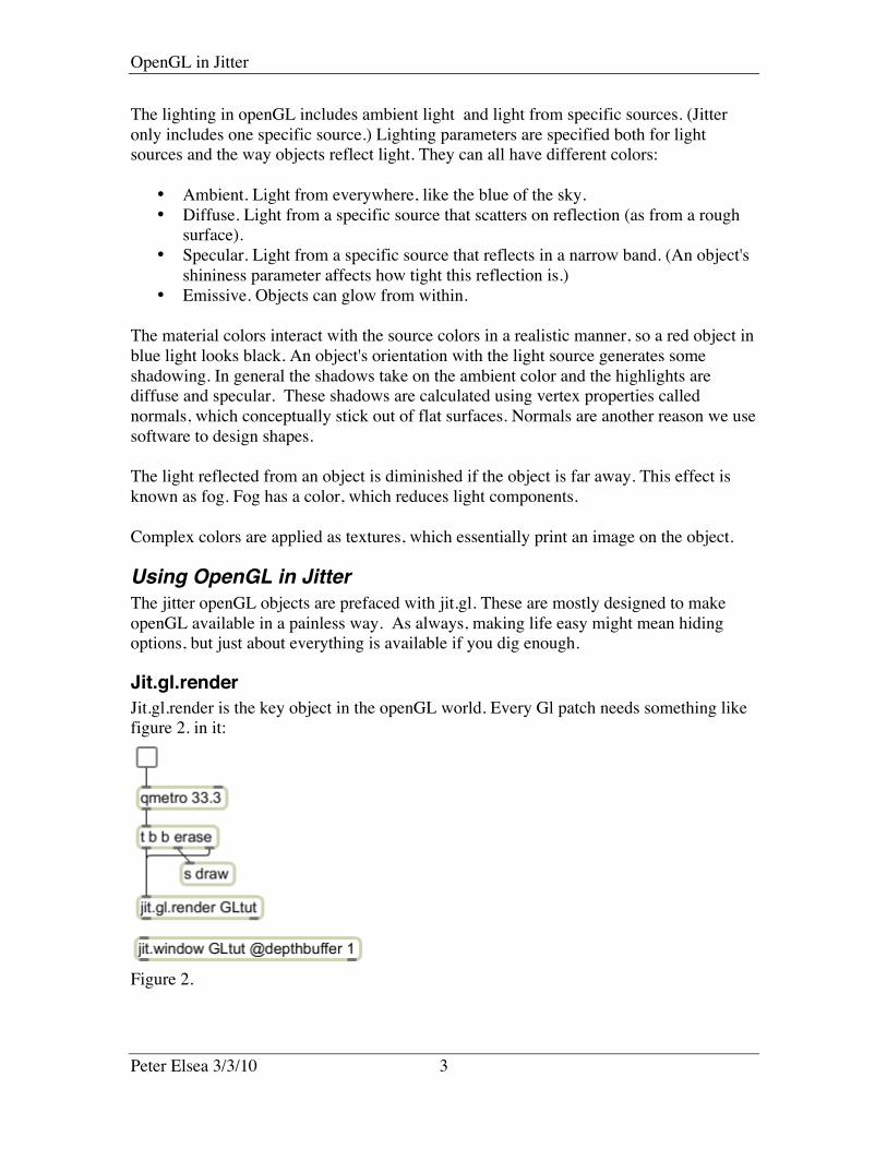
Jit.gl.renderJit.gl.render is the key object in the openGL world. Every Gl patch needs something likefigure 2. in it:
Figure 2.
OpenGL in Jitter
Peter Elsea 3/3/10 4
The argument in jit.gl.render is the "drawing context". All jit.gl objects with this namewill be created in this context, and the results displayed in a jit.window2 or pwindow ofthe same name (you can name a pwindow with its inspector.) The qmetro clocks screenupdates in the usual way. The erase message clears the windows, the bang sent to draw(or other destination of your choice) may be useful for mechanisms that affect thedrawing, and the bang directly to render draws the image.
Note you can only draw to one destination. That destination can be a jit.matrix if youneed the image in more than one place. Unfortunately, drawing to a matrix uses CPUrendering instead of the graphics card, so there is a significant loss of efficiency.
No more connections to jit.render are needed for basic drawing. Other attributes can beset, and I'll cover them as I go along. The actual drawing is handled by a variety ofdrawing objects, which interact with the render object via the context name. There is nolimit to the number of objects that can be connected to a single render context, but themore you ask jitter to do the slower it runs. Most drawing is amazingly fast-- I havedrawn a hundred objects with no noticeable slowing.
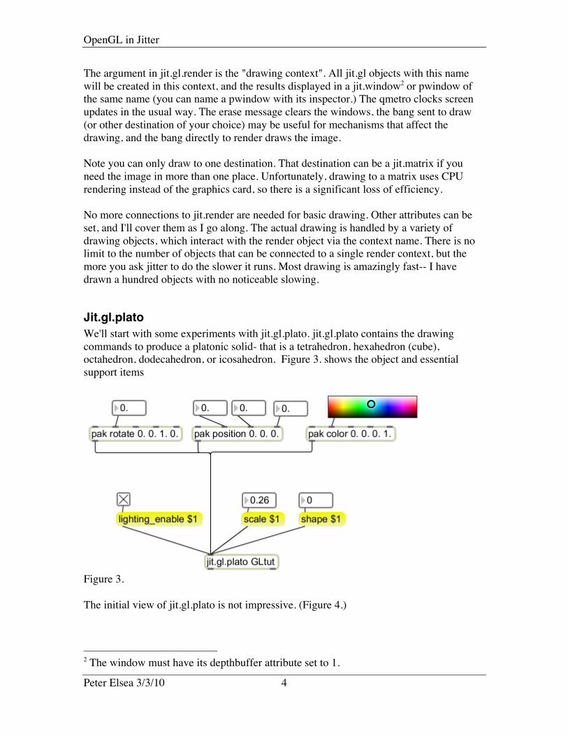
Jit.gl.platoWe'll start with some experiments with jit.gl.plato. jit.gl.plato contains the drawingcommands to produce a platonic solid- that is a tetrahedron, hexahedron (cube),octahedron, dodecahedron, or icosahedron. Figure 3. shows the object and essentialsupport items
Figure 3.
The initial view of jit.gl.plato is not impressive. (Figure 4.)
2 The window must have its depthbuffer attribute set to 1.
OpenGL in Jitter
Peter Elsea 3/3/10 5
Figure 4.This is a tetrahedron too big to fit in the window, with no color or lighting.
• The scale message will modify the size. Scale can take one or three arguments.With three, the form can be distorted.
• The message lighting_enable 1 will turn on lighting for the object. Without, it'sjust a grey blob.
• Rotate to see the shape better. Rotate takes four arguments, one for an angle, andthree to define the axis to rotate about. Rotatexyz takes three arguments forrotation about the X,Y and Z axes. (In degrees.)
• Set a color with the message color RGBA. The values should be between 0 and 1,just perfect for the new version of swatch. (This is a simplified color scheme.Advanced color features will be discussed later.)
• Move the object with the message position X Y Z.• Change the shape with the message shape 1-5. You can also use the shape names.
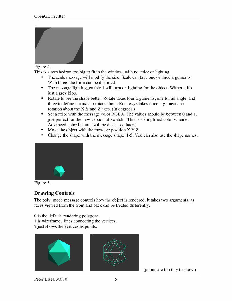
Figure 5.
Drawing ControlsThe poly_mode message controls how the object is rendered. It takes two arguments, asfaces viewed from the front and back can be treated differently.
0 is the default, rendering polygons.1 is wireframe, lines connecting the vertices.2 just shows the vertices as points.
(points are too tiny to show )

OpenGL in Jitter
Peter Elsea 3/3/10 6
Figure 6.
The cull_face message prevents rendering of some faces. Mode 0 (default) does noculling, 1 culls back faces, and 2 culls the front. The documentation disagrees withreality. This has all been a bit buggy, so I suggest leaving the default on.
A parameter called smooth_shading can set the color to blend from vertex to vertex. Thisdoesn't matter on the angular objects like jit.gl.plato, but it will make nearly curvedobjects like jit.gl.gridshape seem smooth.
A parameter called depth_enable turns on the 3D mechanisms. If your objects appearabsolutely bonkers, check that this is on.
Advanced ColorYou can get more detailed control of object color by working with the individual materialqualities. These interact with the lighting qualities which can be set by commands sent tothe associated jit.gl.render object.
Figure 7.The color command can be shut off with the message auto_material 0. This leaves a blackobject.
Figure 8.The message mat_emission RGBA sets the object to glow. Note that there are noshadows.

OpenGL in Jitter
Peter Elsea 3/3/10 7
Figure 9.The message mat_ambient RGBA sets the color that is reflected from ambient light. Thisinteracts with the light_ambient setting of the render context. Light_ambient seems todefault to around 0.1 0.1 0.1. This will reflect true color, but dimly. Mat-ambient is thecolor in the shadows.
Figure 10.The message mat_difuse RGBA sets the color as reflected from directional light. Thisinteracts with light_diffuse, which is normally 1 1 1. The intensity of reflection varieswith the angle between a face and the light source. You get the maximum color when thenormal of the surface points at the light. The position of the light can be changed by themessage light_position X Y Z to the render object.
Figure 11.The message mat_specular RGBA sets the color of the faces that have the most directpath from the light to the point of view. (The reflection path.) This interacts withlight_specular for color, and light_position to determine the facets that are affected. Themessage shininess affects the width of the reflection zone.
The alpha channel will have no effect on object colors until their blend_enable attribute isturned on.

OpenGL in Jitter
Peter Elsea 3/3/10 8
TexturesTextures apply arbitrary patterns to objects. A texture is defined in the render object, thenthat texture is assigned to other objects. There are several ways to define textures, but theeasiest is:
• Send a matrix to a [prepend texture somename] object and on to the render object.The matrix becomes the texture. Any matrix source may be used, including movieor grab.
• Send the message (texture somename) to the drawing object. The texture imagewill now be applied to the object.
The appearance of the texture may be modified by the tex_map message to the drawingobject. There are four modes
0. Default (varies with object).1. Object linear. The texture is attached to the object. When we look at the
jit.gl.sketch object we'll see how this is specified.2. Sphere map. The texture is reflected from the object.3. Eye linear. As if you are looking through the object at the texture.
There are ways of modifying the texture dimensions via the render object, but it is franklybetter to take care of that sort of thing before sending an image to texture. One thing isnot made clear- textures are assumed to be square. Any other aspect ratio is interpolateddown to a square shape.
The tex_plane_s and tex_plane_t messages can be used to adjust the texture size relativeto the object size in modes 1 and 3 which use automatically generated texturecoordinates. The approach is a bit arcane, but this is how it goes:Each point on the surface of an object is represented by four(!) values, x, y, z, w, where wis used only for transformations of the point. It is usually left at 1, and our familiar triad isx/w, y/w, z/w. The tex_plane messages define how the points on the texture are related topoints on the surface of an object. The points on the texture (which is two dimensional)are defined as s, and t, similar to x and y. Each vertex of an object is given an s and tcomponent to define what spot on the texture should hit that vertex. (Object designprograms let us specify these values.) The tex_plane messages have 4 arguments, givenas a, b, c, d in the reference.
Tex_plane_s a b c d sets the s coordinate for each vertex as ax+by+cz+dw with x, y, z,and w the coordinates of the vertex. Likewise tex_plane_t sets the t coordinate for eachvertex. In mode 1 the vertex coordinates are taken from the coordinates of the facet, sothe texture moves and turns with the object. In Mode 3 the vertex coordinates are inglobal space, so the texture changes as the object moves. By some experimentation on acube you will find:
• Changing a in the s term stretches the texture in the horizontal direction.• Changing b in the t term stretches the texture in the vertical direction.• Changing the sign of either of those reverses the image.

OpenGL in Jitter
Peter Elsea 3/3/10 9
• If you change b in the s term or a in the t term, the image is skewed.• Changing c in the s term stretches in the horizontal and wraps around the sides.• Changing c in the t term stretches in the vertical and wraps around the top and
bottom.• If you change c in both, the texture is skewed.• Changing either d shifts the texture.
All of this is affected by how the object is initially constructed. For instance, vertexcoordinates are specified relative to an object's origin, which is the center of thejit.gl.plato but the bottom left of jit.gl.text3D. So an image that nicely covers text willhave corners in the center of a platonic object. You can see this in figure 12.
Figure 12.You will quickly notice that textures from matrices appear upside down. This is due tothe conflict between QuickTime and openGL coordinate systems. In QuickTime, thevertical component is positive going down the screen. (Remember 0,0 is in the upper leftcorner.) In OpenGL Y is positive going up.
There is also a jit.gl.texture object which allows much more detailed control of a texture.It's complicated enough that it probably needs its own tutorial. The jit.gl.shader objectcreates textures that interact with objects in a more complex way. There is an excellenttutorial in the jitter tutorial set.

OpenGL in Jitter
Peter Elsea 3/3/10 10
A quick rundown of some OpenGL objects:
Jit.gl.gridshape
Figure 13.
Jit.gl.gridshape produces rounded objects: sphere, torus, cylinder, cube, plane, circle.Otherwise it is pretty much interchangeable with jit.gl.plato. The smooth_shadingattribute will give a nice rounded look.
Text Objects
Jit.gl.text2d Jit.gl.text3dFigure 14.The text2d object prints on the window, with no concern for Z. You can set fonts, size,and alignment, rotate the angle and so forth. All other objects appear behind the text. Thetext3d object creates movie poster text with adjustable depth.
Jit.gl.videoplane
Figure 15.
OpenGL in Jitter
Peter Elsea 3/3/10 11
Jit.gl.videoplane is a sort of movie screen that you can position in space. Any matrix fedto it will be displayed-- this includes movies and grab output.
The default size of the videoplane is 2.0 x 2.0. To precisely fit a 4:3 window, scalejit.videoplanre to 1.11, 0.843. When an openGL window is resized, objects are resizedaccording to the Y dimension but keep their overall proportions. This means that when awindow displaying a videoplane is expanded to fullscreen, there will usually be extrablank space at the edges.
Any color assigned to jit.gl.videoplane will interact with the color of the image. Ifblend_enable is 1, the alpha value will fade the image in the videoplane, but thevideoplane will still block the view of other objects.
The image in videoplane is a texture, so texture values apply to some extent. There aresome texture messages special to jit.gl.videoplane. tex_scale_x and tex_scale_y willzoom in on the image if the value is greater than 1. Then the tex_ofset_x and tex_offset_ymessages will move within the enlarged image.
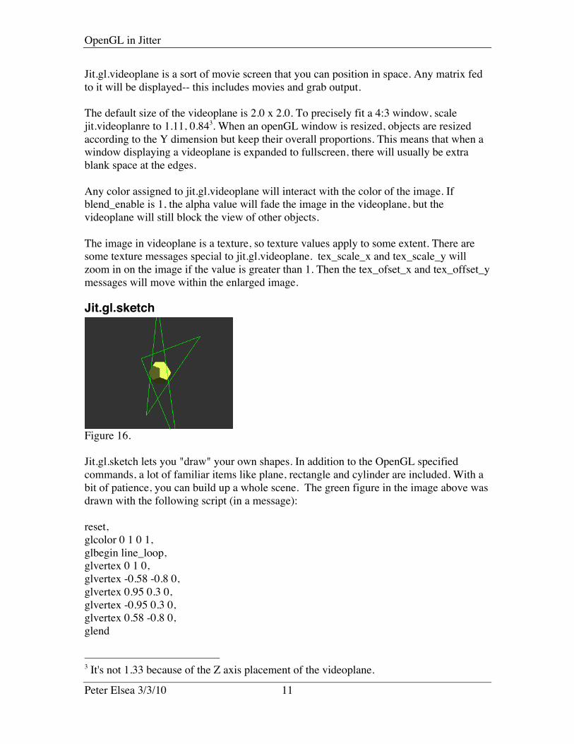
Jit.gl.sketch
Figure 16.
Jit.gl.sketch lets you "draw" your own shapes. In addition to the OpenGL specifiedcommands, a lot of familiar items like plane, rectangle and cylinder are included. With abit of patience, you can build up a whole scene. The green figure in the image above wasdrawn with the following script (in a message):
reset,glcolor 0 1 0 1,glbegin line_loop,glvertex 0 1 0,glvertex -0.58 -0.8 0,glvertex 0.95 0.3 0,glvertex -0.95 0.3 0,glvertex 0.58 -0.8 0,glend
3 It's not 1.33 because of the Z axis placement of the videoplane.

OpenGL in Jitter
Peter Elsea 3/3/10 12
These are drawing commands sent to jit.gl.sketch. Once a command is sent, it ismaintained in an internal list and executed each time jit.gl.sketch draws itself. The orderin which commands are executed is often important. There are commands that directlymanipulate the list, for instance by inserting a command at a specific point. Thecommand list is cleared by the reset command.
The coordinates in various commands are based on the point set by the position of thejit.gl.sketch object. They are also relative to the front view-- i.e. a rotation of 0 in all axes.That way rotate and position move everything specified in the sketch as a unit. Theeasiest way to work out the vertex coordinates is to plan your sketch on graph paper. Thecommand axes 1 will show the origin and axes-- this can help line up parts of a complexdrawing.
A complete understanding of jit.gl.sketch is a complete understanding of the openGLlanguage, but here's a sampling of the commands.
Basic gl sketch commandsReset clears the jit.gl.sketch command list. (glclear erases the entire window-- allobjects!)glcolor sets the color for what is about to be drawnglbegin sets the drawing primitive. Favorites are line_loop and triangles.glvertex defines each vertex for the primitive. These will be connected according to theactive primitive. Remember that vertices must be specified in counterclockwise order topresent the front of a triangle to the camera.glend marks the end of a primitive. (This can be skipped.)
Texture sketch commandsglbindtexture "name" attaches a texture to the following vertices. (The usual texturecommands work on the whole object.)gltexcoord s t, Each vertex must be preceded by this to properly map the texture to theprimitive. gltexcoord 0. 0. specifies the upper left corner of the texture, 1. 1. is the lowerright.
QuickDraw style sketch commandsThere are a set of commands reminiscent of the lcd commands. These can be freelymixed with some gl style commands, like glcolor.
Moveto establishes a base point for the following operations.lineto x y draws a line from the moveto point to x, ylinesegment x1 y1 z1 x2 y2 z2 draws a line from point xyz1 to xyz2.shapeorient rot-x rot-y rot-z defines a plane for 2D drawing commands.shapeslice a b sets resolution of 2D and 3D drawing commands. Low values make roundshapes blocky.circle r draws a filled circle of radius r. Additional arguments set start and end angle indegrees.framecircle r draws an unfilled circle of radius r

OpenGL in Jitter
Peter Elsea 3/3/10 13
elipse r1 r2 draws a filled ellipse of radius r1(along x) and r2 (along y)framellipse r1 r2 draws an unfilled ellipse of radius r1(along x) and r2 (along y)plane x y draws a plane using the vertices of x y, -x y, -x -y, x -y.roundedplane r x y draws a plane as above, with corners rounded as per r.sphere r draws a 3D sphere with radius r. Additional arguments set start and end angles(in degrees) on x and y axis.torus r t draws a torus (doughnut) with a radius r and thickness t.cylinder r1 r2 d draws a cylinder with front radius r1, back radius r2 and depth d. Thedefault shape slice makes this pretty rough.cube x y z draws a brick with dimensions of 2*x, 2*y and 2*z.
There is a lot more to jit.gl.sketch. For instance, you can include any of the jit.gl objectsin a sketch by referring to their @name attributes (drawobject). Many techniques areillustrated in the helpfile, and there is an extensive tutorial. For true mastery, studyopenGL online. The actual redbook is pretty daunting, but there are many online tutorials.
Jit.gl.model
Figure 17.
Jit.gl.model lets you load in objects created in real 3D modeling programs such as Mayaor Wings3D. The model must be in the .obj format, which is widely supported. This willusually be at least two files (which should be in the same folder). The .obj file containsthe geometry and the .mtl file contains the material information. It may refer to other filesfor textures. It is possible if tedious to write .obj files by hand, but I don't recommend it.It's worth learning what's in them, because you might want to make a simple edit ofsomeone else's file. (For instance, I did that to change the color of the teapot above.)
If a model does not have a .mtl file, the usual texture and color methods will apply4. It ispossible for models to contain groups. If they do, each group can have its own texture.The drawgroup command can choose one of the groups to display.
4 You can detach an .obj file from its .mtl file by using # to comment out the mtlibstatement in the .obj file. Viz. #mtllib teapot.mtl
OpenGL in Jitter
Peter Elsea 3/3/10 14
Jit.gl.handle
Figure 18.
Jit.gl.handle allows mouse interaction to rotate the image. Jit.gl.handle can be attached toa single object or the render object. In the latter case, the entire view is rotated. (Set thejit.gl.handle object's inherit_transform to 1 when you do this.) When the mouse is clickedon the window, axes orbits appear, and dragging the mouse perform the rotation. Youcan have multiple handles in a scene, but their behavior is likely to be a bit chaotic--reducing the handle radius will help.
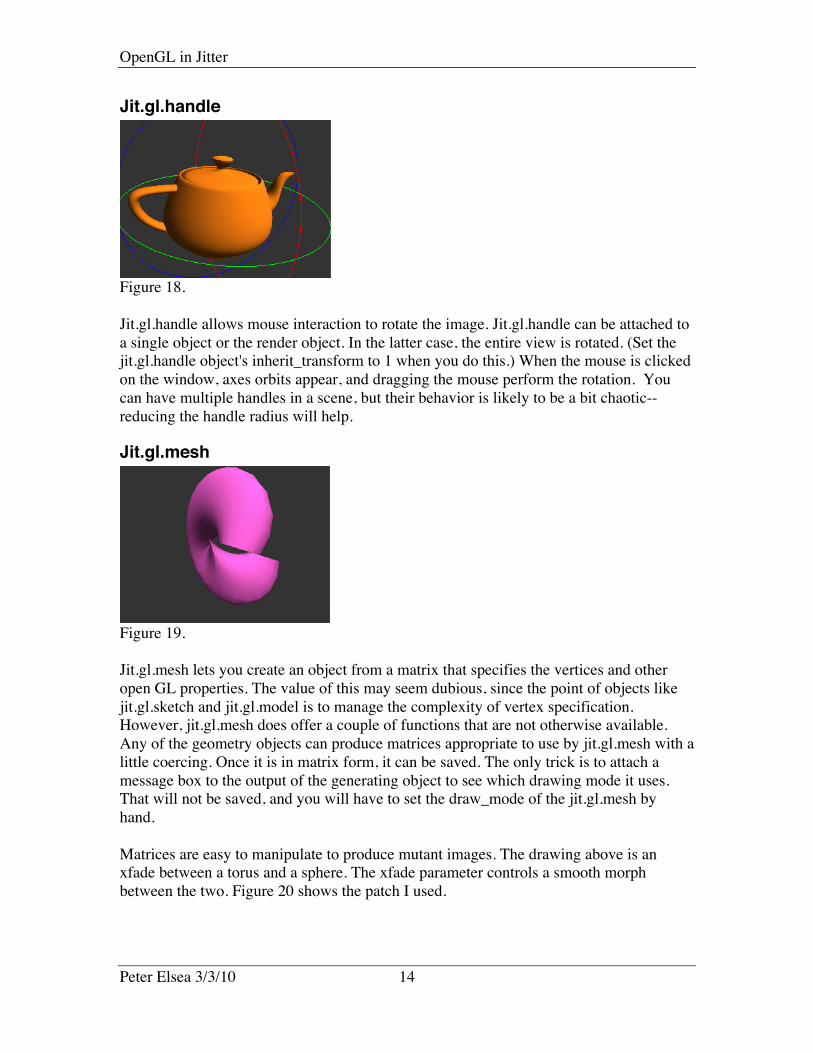
Jit.gl.mesh
Figure 19.
Jit.gl.mesh lets you create an object from a matrix that specifies the vertices and otheropen GL properties. The value of this may seem dubious, since the point of objects likejit.gl.sketch and jit.gl.model is to manage the complexity of vertex specification.However, jit.gl.mesh does offer a couple of functions that are not otherwise available.Any of the geometry objects can produce matrices appropriate to use by jit.gl.mesh with alittle coercing. Once it is in matrix form, it can be saved. The only trick is to attach amessage box to the output of the generating object to see which drawing mode it uses.That will not be saved, and you will have to set the draw_mode of the jit.gl.mesh byhand.
Matrices are easy to manipulate to produce mutant images. The drawing above is anxfade between a torus and a sphere. The xfade parameter controls a smooth morphbetween the two. Figure 20 shows the patch I used.

OpenGL in Jitter
Peter Elsea 3/3/10 15
Figure 20.
Jit.gl.multiple
Figure 21.
Jit.gl.multiple copies objects created from jit.gl items such as jit.gl.plato. If you needseveral similar objects, multiple is an efficient way of getting them. It can be a bit trickyto set up, because the parameters of the copies are controlled in matrices, one each forposition, scale, rotate (or rotatexyx) color, and texture. The number of cells in the arraysdetermine the number of copies. Each array is float32, with 3 or 4 panes depending onwhat is controlled. The documentation skips a lot, but here are some vital clues:
• The attribute @targetname must match the @name of the object you wish tocopy.
• There must be a @glparams attribute with a list of parameters to independentlycontrol. If position is not on the list, all copies occupy the same space.
• An int argument will produce inlets to connect control matrices-- these match theglparams list.
• Targetmode affects the influence of parameters of the original on the copies. Iftargetmode is 1, Scaling, position, etc of the original are ignored. You can movethe original offscreen to hide it, and the copies will remain where the positionmatrix puts them.

OpenGL in Jitter
Peter Elsea 3/3/10 16
• If targetmode is 0, the values in the control matrix interact with the parameters ofthe original: the position matrix defines an offset from the original's origin whichis multiplied by the original's scale. The scale matrix is multiplied by theoriginal's scale. A color matrix replaces the original's color.
• You must supply a matrix to set all of the parameters in the glparams list beforethe copies will be displayed.
• The message [position_matrix pmat] will copy the values from a matrix named"pmat" to set the position values. Similar messages apply to the other glparams.This is not a connection-- the message must be resent every time the controlmatrix is updated5.
Generating control matrices is going to be complex. Figure 22 illustrates a brute forceapproach appropriate for a few copies.
Figure 22.
Figure 22 produced the image in figure 21. There are matrices to control position,rotation, scale and color. Since the matrices all have dimension 3, there are 3 copies. Thecells in each control matrix are set by setcell commands. I have encapsulated most of thisto clarify the example.
5 You can leave the inlet argument off when you do this, but you still must list the@glparams.
OpenGL in Jitter
Peter Elsea 3/3/10 17
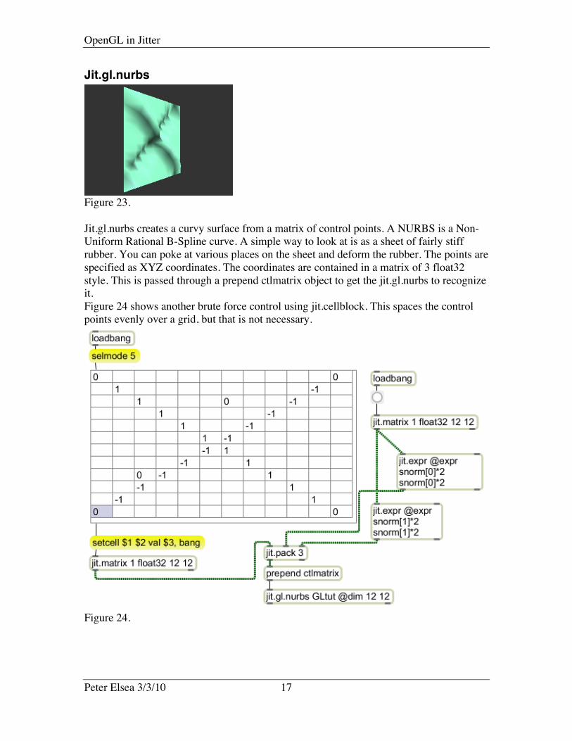
Jit.gl.nurbs
Figure 23.
Jit.gl.nurbs creates a curvy surface from a matrix of control points. A NURBS is a Non-Uniform Rational B-Spline curve. A simple way to look at is as a sheet of fairly stiffrubber. You can poke at various places on the sheet and deform the rubber. The points arespecified as XYZ coordinates. The coordinates are contained in a matrix of 3 float32style. This is passed through a prepend ctlmatrix object to get the jit.gl.nurbs to recognizeit.Figure 24 shows another brute force control using jit.cellblock. This spaces the controlpoints evenly over a grid, but that is not necessary.
Figure 24.

OpenGL in Jitter
Peter Elsea 3/3/10 18
Jit.gl.graph
Figure 25.
Jit.gl.graph lets you create a 3 dimensional graph of changing data. It's the same asjit.graph, but can be rotated in three dimensions. Figure 25 shows it used with jit.catch~.
Jit.gl.volume
Figure 26.
Jit.gl.volume visualizes a volumetric density map (in the words of the documentation). Avolumetric density map is a 3 dimensional matrix with a number in each cell thatspecifies density. (Imagine a stack of glass bricks-- some are cloudy, some are clear. Thedensity value is how cloudy each is.) The problem with using jit.gl.volume is producingthree dimensional matrices with interesting patterns. It's not hard to "stretch" a twodimensional image into jit.gl.volume. Figure 27 shows how to do this with jit.graph.
True 3D volumes require virtuoso matrix manipulation, probably with jit.expr. Forinstance the second image of figure 26 was produced with the expression:
""in[0] *(1(abs(cos(norm[0]*TWOPI))*(abs(cos(norm[1]*TWOPI))*(abs(cos(norm[2]*TWOPI)))"
• The scale message to jit.gl.volume does not affect the size of the image. Instead, itshaves off outer layers, revealing the inner structure.
• The full structure is 2 x 2 x 2. With the origin at 0 0 0, this places the fieldsomewhat outside the view frustrum. Moving the origin to 0 0 -1 make it visible.
• The density and intensity values interact in mysterious ways. While the docsspeak of defaults of 0.5, values applied via messages are divided by 1000, sothat's is equivalent to density 500. For any given intensity there is a range ofdensity from a solid cube to nothing. The transitions tend to be abrupt. For any

OpenGL in Jitter
Peter Elsea 3/3/10 19
density, intensity is cyclical, with values that bloom and values that disappear.The best results come from using density to get as fine an image as you can, thentweak intensity by very small amounts.
• Higher resolution is possible by turning on the cubes attribute. Then the slicesparameter will determine how fine a line can be produced.
OthersSome gl type objects use the video display processors for other purposes. For instance,Jit.gl.slab is a programmable matrix processor. Since it runs in the video processor, it isabout 100 times faster than standard jitter operators like rota. This is discussed in atutorial called Shaders in Jitter.