OpenFlow SecAnalysis
117
Institut für T echnische Informatik und Kommunikationsnetze Rowan Kl¨ oti OpenFlow: A Security Analysis Master Thesis MA-2012-20 October 15, 2012 to April 14, 2013 Tutor: Vasileios Kotronis Co-Tutor: Paul Smith Supervisor: Prof. Bernhard Plattner
Transcript of OpenFlow SecAnalysis
Institut fürTechnische Informatik undKommunikationsnetze
Rowan Kloti
OpenFlow: A Security Analysis
Master Thesis MA-2012-20October 15, 2012 to April 14, 2013
Tutor: Vasileios KotronisCo-Tutor: Paul SmithSupervisor: Prof. Bernhard Plattner


Abstract
This report contains a security analysis of the OpenFlow 1.0 protocol and the FlowVisor extensionusing the STRIDE method, as well as a description of possible attack methods using attack treesand a textual description of such attacks. The feasability of the attacks is analysed, and apractical demonstration of a number of the described attacks is performed. Subsequently, thereis a discussion of countermeasures and mitigations. A review of newer OpenFlow specificationsis also included.

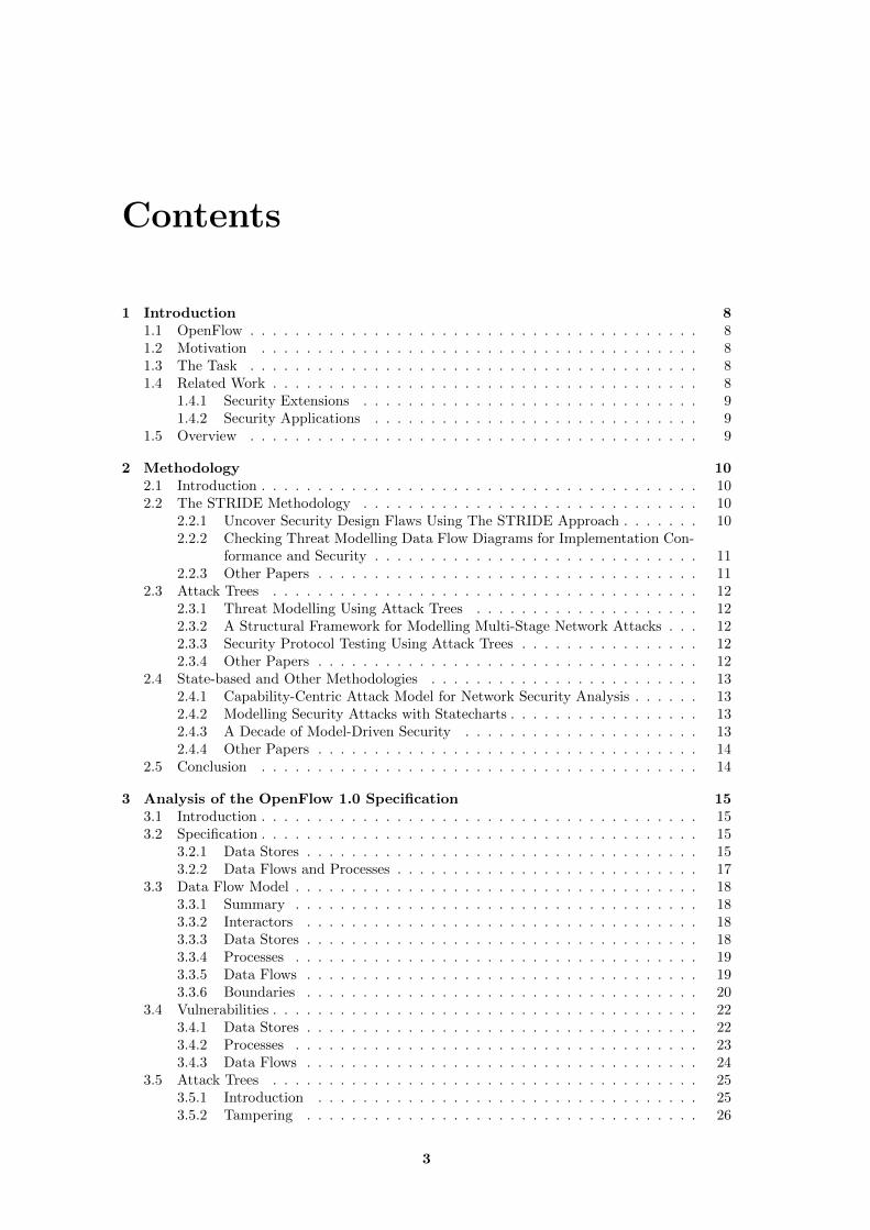
Contents
1 Introduction 81.1 OpenFlow . . . . . . . . . . . . . . . . . . . . . . . . . . . . . . . . . . . . . . . . 81.2 Motivation . . . . . . . . . . . . . . . . . . . . . . . . . . . . . . . . . . . . . . . 81.3 The Task . . . . . . . . . . . . . . . . . . . . . . . . . . . . . . . . . . . . . . . . 81.4 Related Work . . . . . . . . . . . . . . . . . . . . . . . . . . . . . . . . . . . . . . 8
1.4.1 Security Extensions . . . . . . . . . . . . . . . . . . . . . . . . . . . . . . 91.4.2 Security Applications . . . . . . . . . . . . . . . . . . . . . . . . . . . . . 9
1.5 Overview . . . . . . . . . . . . . . . . . . . . . . . . . . . . . . . . . . . . . . . . 9
2 Methodology 102.1 Introduction . . . . . . . . . . . . . . . . . . . . . . . . . . . . . . . . . . . . . . . 102.2 The STRIDE Methodology . . . . . . . . . . . . . . . . . . . . . . . . . . . . . . 10
2.2.1 Uncover Security Design Flaws Using The STRIDE Approach . . . . . . . 102.2.2 Checking Threat Modelling Data Flow Diagrams for Implementation Con-
formance and Security . . . . . . . . . . . . . . . . . . . . . . . . . . . . . 112.2.3 Other Papers . . . . . . . . . . . . . . . . . . . . . . . . . . . . . . . . . . 11
2.3 Attack Trees . . . . . . . . . . . . . . . . . . . . . . . . . . . . . . . . . . . . . . 122.3.1 Threat Modelling Using Attack Trees . . . . . . . . . . . . . . . . . . . . 122.3.2 A Structural Framework for Modelling Multi-Stage Network Attacks . . . 122.3.3 Security Protocol Testing Using Attack Trees . . . . . . . . . . . . . . . . 122.3.4 Other Papers . . . . . . . . . . . . . . . . . . . . . . . . . . . . . . . . . . 12
2.4 State-based and Other Methodologies . . . . . . . . . . . . . . . . . . . . . . . . 132.4.1 Capability-Centric Attack Model for Network Security Analysis . . . . . . 132.4.2 Modelling Security Attacks with Statecharts . . . . . . . . . . . . . . . . . 132.4.3 A Decade of Model-Driven Security . . . . . . . . . . . . . . . . . . . . . 132.4.4 Other Papers . . . . . . . . . . . . . . . . . . . . . . . . . . . . . . . . . . 14
2.5 Conclusion . . . . . . . . . . . . . . . . . . . . . . . . . . . . . . . . . . . . . . . 14
3 Analysis of the OpenFlow 1.0 Specification 153.1 Introduction . . . . . . . . . . . . . . . . . . . . . . . . . . . . . . . . . . . . . . . 153.2 Specification . . . . . . . . . . . . . . . . . . . . . . . . . . . . . . . . . . . . . . . 15
3.2.1 Data Stores . . . . . . . . . . . . . . . . . . . . . . . . . . . . . . . . . . . 153.2.2 Data Flows and Processes . . . . . . . . . . . . . . . . . . . . . . . . . . . 17
3.3 Data Flow Model . . . . . . . . . . . . . . . . . . . . . . . . . . . . . . . . . . . . 183.3.1 Summary . . . . . . . . . . . . . . . . . . . . . . . . . . . . . . . . . . . . 183.3.2 Interactors . . . . . . . . . . . . . . . . . . . . . . . . . . . . . . . . . . . 183.3.3 Data Stores . . . . . . . . . . . . . . . . . . . . . . . . . . . . . . . . . . . 183.3.4 Processes . . . . . . . . . . . . . . . . . . . . . . . . . . . . . . . . . . . . 193.3.5 Data Flows . . . . . . . . . . . . . . . . . . . . . . . . . . . . . . . . . . . 193.3.6 Boundaries . . . . . . . . . . . . . . . . . . . . . . . . . . . . . . . . . . . 20
3.4 Vulnerabilities . . . . . . . . . . . . . . . . . . . . . . . . . . . . . . . . . . . . . . 223.4.1 Data Stores . . . . . . . . . . . . . . . . . . . . . . . . . . . . . . . . . . . 223.4.2 Processes . . . . . . . . . . . . . . . . . . . . . . . . . . . . . . . . . . . . 233.4.3 Data Flows . . . . . . . . . . . . . . . . . . . . . . . . . . . . . . . . . . . 24
3.5 Attack Trees . . . . . . . . . . . . . . . . . . . . . . . . . . . . . . . . . . . . . . 253.5.1 Introduction . . . . . . . . . . . . . . . . . . . . . . . . . . . . . . . . . . 253.5.2 Tampering . . . . . . . . . . . . . . . . . . . . . . . . . . . . . . . . . . . 26
3
4 CONTENTS
3.5.3 Information Disclosure . . . . . . . . . . . . . . . . . . . . . . . . . . . . . 283.5.4 Denial of Service . . . . . . . . . . . . . . . . . . . . . . . . . . . . . . . . 323.5.5 Attack Prerequisites . . . . . . . . . . . . . . . . . . . . . . . . . . . . . . 35
4 Changes Introduced in Newer Versions of OpenFlow 394.1 Introduction . . . . . . . . . . . . . . . . . . . . . . . . . . . . . . . . . . . . . . . 394.2 History . . . . . . . . . . . . . . . . . . . . . . . . . . . . . . . . . . . . . . . . . 394.3 OpenFlow Switch Specification 1.1.0 . . . . . . . . . . . . . . . . . . . . . . . . . 40
4.3.1 Outline of Changes . . . . . . . . . . . . . . . . . . . . . . . . . . . . . . . 404.3.2 Multiple Flow Tables . . . . . . . . . . . . . . . . . . . . . . . . . . . . . . 404.3.3 Group Table . . . . . . . . . . . . . . . . . . . . . . . . . . . . . . . . . . 404.3.4 Emergency Flow Cache . . . . . . . . . . . . . . . . . . . . . . . . . . . . 414.3.5 Message Handling Semantics . . . . . . . . . . . . . . . . . . . . . . . . . 414.3.6 VLAN Tags . . . . . . . . . . . . . . . . . . . . . . . . . . . . . . . . . . . 414.3.7 Summary . . . . . . . . . . . . . . . . . . . . . . . . . . . . . . . . . . . . 42
4.4 OpenFlow Switch Specification 1.2 . . . . . . . . . . . . . . . . . . . . . . . . . . 424.4.1 Outline of Changes . . . . . . . . . . . . . . . . . . . . . . . . . . . . . . . 424.4.2 Field Matching and Rewriting . . . . . . . . . . . . . . . . . . . . . . . . 424.4.3 Packet Buffering . . . . . . . . . . . . . . . . . . . . . . . . . . . . . . . . 434.4.4 Multiple Controllers . . . . . . . . . . . . . . . . . . . . . . . . . . . . . . 434.4.5 IPv6 Support . . . . . . . . . . . . . . . . . . . . . . . . . . . . . . . . . . 434.4.6 Summary . . . . . . . . . . . . . . . . . . . . . . . . . . . . . . . . . . . . 43
4.5 OpenFlow Switch Specification 1.3.0 . . . . . . . . . . . . . . . . . . . . . . . . . 444.5.1 Outline of Changes . . . . . . . . . . . . . . . . . . . . . . . . . . . . . . . 444.5.2 Unmatched Packets . . . . . . . . . . . . . . . . . . . . . . . . . . . . . . 444.5.3 IPv6 Extension Header Handling . . . . . . . . . . . . . . . . . . . . . . . 444.5.4 Meters . . . . . . . . . . . . . . . . . . . . . . . . . . . . . . . . . . . . . . 444.5.5 Event Filtering . . . . . . . . . . . . . . . . . . . . . . . . . . . . . . . . . 444.5.6 Auxiliary Connections . . . . . . . . . . . . . . . . . . . . . . . . . . . . . 454.5.7 Summary . . . . . . . . . . . . . . . . . . . . . . . . . . . . . . . . . . . . 45
4.6 OpenFlow Switch Specification 1.3.1 . . . . . . . . . . . . . . . . . . . . . . . . . 454.6.1 Outline of Changes . . . . . . . . . . . . . . . . . . . . . . . . . . . . . . . 454.6.2 Summary . . . . . . . . . . . . . . . . . . . . . . . . . . . . . . . . . . . . 45
4.7 Conclusion . . . . . . . . . . . . . . . . . . . . . . . . . . . . . . . . . . . . . . . 46
5 Experimental Examination 475.1 Introduction . . . . . . . . . . . . . . . . . . . . . . . . . . . . . . . . . . . . . . . 475.2 Evaluation of Security Vulnerabilities . . . . . . . . . . . . . . . . . . . . . . . . . 47
5.2.1 Tampering . . . . . . . . . . . . . . . . . . . . . . . . . . . . . . . . . . . 475.2.2 Information Disclosure . . . . . . . . . . . . . . . . . . . . . . . . . . . . . 475.2.3 Denial of Service . . . . . . . . . . . . . . . . . . . . . . . . . . . . . . . . 485.2.4 Conclusion . . . . . . . . . . . . . . . . . . . . . . . . . . . . . . . . . . . 48
5.3 System Setup . . . . . . . . . . . . . . . . . . . . . . . . . . . . . . . . . . . . . . 485.3.1 Overview of Setup . . . . . . . . . . . . . . . . . . . . . . . . . . . . . . . 485.3.2 Virtualisation Software . . . . . . . . . . . . . . . . . . . . . . . . . . . . 495.3.3 Measurements and Observations . . . . . . . . . . . . . . . . . . . . . . . 515.3.4 Attacking System . . . . . . . . . . . . . . . . . . . . . . . . . . . . . . . . 51
5.4 Execution and Results . . . . . . . . . . . . . . . . . . . . . . . . . . . . . . . . . 515.4.1 Denial of Service . . . . . . . . . . . . . . . . . . . . . . . . . . . . . . . . 515.4.2 Information Disclosure . . . . . . . . . . . . . . . . . . . . . . . . . . . . . 54
6 Prevention and Mitigation 586.1 Introduction . . . . . . . . . . . . . . . . . . . . . . . . . . . . . . . . . . . . . . . 586.2 Denial of Service . . . . . . . . . . . . . . . . . . . . . . . . . . . . . . . . . . . . 60
6.2.1 Rate Limiting, Event Filtering, Packet Dropping and Timeout Adjustment 616.2.2 Flow Aggregation . . . . . . . . . . . . . . . . . . . . . . . . . . . . . . . . 626.2.3 Attack Detection . . . . . . . . . . . . . . . . . . . . . . . . . . . . . . . . 626.2.4 Whitelisting and Access Control . . . . . . . . . . . . . . . . . . . . . . . 636.2.5 Firewall and IPS . . . . . . . . . . . . . . . . . . . . . . . . . . . . . . . . 63
CONTENTS 5
6.2.6 Manual Intervention . . . . . . . . . . . . . . . . . . . . . . . . . . . . . . 636.2.7 Hash Collision Prevention . . . . . . . . . . . . . . . . . . . . . . . . . . . 63
6.3 Information Disclosure . . . . . . . . . . . . . . . . . . . . . . . . . . . . . . . . . 636.3.1 Proactive Strategy . . . . . . . . . . . . . . . . . . . . . . . . . . . . . . . 646.3.2 Randomisation . . . . . . . . . . . . . . . . . . . . . . . . . . . . . . . . . 646.3.3 Attack Detection . . . . . . . . . . . . . . . . . . . . . . . . . . . . . . . . 646.3.4 Enforced Equal Response Time . . . . . . . . . . . . . . . . . . . . . . . . 64
6.4 Tampering . . . . . . . . . . . . . . . . . . . . . . . . . . . . . . . . . . . . . . . . 656.4.1 Proactive Strategy . . . . . . . . . . . . . . . . . . . . . . . . . . . . . . . 656.4.2 Timeouts . . . . . . . . . . . . . . . . . . . . . . . . . . . . . . . . . . . . 656.4.3 Integrity Checking . . . . . . . . . . . . . . . . . . . . . . . . . . . . . . . 656.4.4 Access Control . . . . . . . . . . . . . . . . . . . . . . . . . . . . . . . . . 65
7 OpenFlow Extensions 667.1 Introduction . . . . . . . . . . . . . . . . . . . . . . . . . . . . . . . . . . . . . . . 667.2 Architecture . . . . . . . . . . . . . . . . . . . . . . . . . . . . . . . . . . . . . . . 667.3 Data Flow Model . . . . . . . . . . . . . . . . . . . . . . . . . . . . . . . . . . . . 677.4 Vulnerabilities . . . . . . . . . . . . . . . . . . . . . . . . . . . . . . . . . . . . . . 69
7.4.1 Data Stores . . . . . . . . . . . . . . . . . . . . . . . . . . . . . . . . . . . 697.4.2 Processes . . . . . . . . . . . . . . . . . . . . . . . . . . . . . . . . . . . . 707.4.3 Data Flows . . . . . . . . . . . . . . . . . . . . . . . . . . . . . . . . . . . 70
7.5 Conclusion . . . . . . . . . . . . . . . . . . . . . . . . . . . . . . . . . . . . . . . 71
8 Future Work 728.1 Introduction . . . . . . . . . . . . . . . . . . . . . . . . . . . . . . . . . . . . . . . 728.2 Security Modelling . . . . . . . . . . . . . . . . . . . . . . . . . . . . . . . . . . . 728.3 Empirical Testing . . . . . . . . . . . . . . . . . . . . . . . . . . . . . . . . . . . . 72
9 Summary 73
Nomenclature 74
References 77
A Diagram Legends 82A.1 Data Flow Diagram Legend . . . . . . . . . . . . . . . . . . . . . . . . . . . . . . 82A.2 Attack Tree Legend . . . . . . . . . . . . . . . . . . . . . . . . . . . . . . . . . . 83
B Symbols Used 84
C Attack Trees 85
D Code Listings 95D.1 udp-multi . . . . . . . . . . . . . . . . . . . . . . . . . . . . . . . . . . . . . . . . 95D.2 flowrule-overflow-test . . . . . . . . . . . . . . . . . . . . . . . . . . . . . . . . . . 96D.3 mininet-init . . . . . . . . . . . . . . . . . . . . . . . . . . . . . . . . . . . . . . . 97D.4 mininet-custom-topo . . . . . . . . . . . . . . . . . . . . . . . . . . . . . . . . . . 98
D.4.1 Usage . . . . . . . . . . . . . . . . . . . . . . . . . . . . . . . . . . . . . . 98D.4.2 Listing . . . . . . . . . . . . . . . . . . . . . . . . . . . . . . . . . . . . . . 99
D.5 attack-demo-dos . . . . . . . . . . . . . . . . . . . . . . . . . . . . . . . . . . . . 101D.6 dos-timeout-probe . . . . . . . . . . . . . . . . . . . . . . . . . . . . . . . . . . . 104D.7 attack-demo-id . . . . . . . . . . . . . . . . . . . . . . . . . . . . . . . . . . . . . 106D.8 tcp-time . . . . . . . . . . . . . . . . . . . . . . . . . . . . . . . . . . . . . . . . . 110D.9 id-probe . . . . . . . . . . . . . . . . . . . . . . . . . . . . . . . . . . . . . . . . . 111
E Timetable 113
List of Figures
3.1 Data flow diagram of system . . . . . . . . . . . . . . . . . . . . . . . . . . . . . 213.2 Data flow diagram of switch . . . . . . . . . . . . . . . . . . . . . . . . . . . . . . 213.3 Data flow diagram of controller . . . . . . . . . . . . . . . . . . . . . . . . . . . . 223.4 Overview attack tree . . . . . . . . . . . . . . . . . . . . . . . . . . . . . . . . . . 263.5 Tampering attack tree . . . . . . . . . . . . . . . . . . . . . . . . . . . . . . . . . 273.6 Information disclosure attack tree . . . . . . . . . . . . . . . . . . . . . . . . . . . 303.7 Subtree for determining whether aggregation is in use . . . . . . . . . . . . . . . 323.8 Denial of service attack tree . . . . . . . . . . . . . . . . . . . . . . . . . . . . . . 333.9 Subtree for multiple client interface access . . . . . . . . . . . . . . . . . . . . . . 363.10 Subtree for management interface access . . . . . . . . . . . . . . . . . . . . . . . 373.11 Subtree for producing a predictable response (for timing analysis) . . . . . . . . . 38
5.1 Schematic diagram of simple virtual network setup . . . . . . . . . . . . . . . . . 495.2 Schematic diagram of advanced virtual network setup . . . . . . . . . . . . . . . 505.3 Test with data link at 100 Mbps, 10 ms delay, control link at 100 Mbps, 1 ms delay 535.4 Test with data link at 100 Mbps, 10 ms delay, control link at 10 Mbps, 10 ms delay 535.5 Control using forwarding.l3 learning controller with symmetric timing at 10 ms 555.6 Using forwarding.l3 aggregator simple controller with symmetric timing at 10 ms 555.7 Using forwarding.l3 aggregator simple controller with asymmetric timing at 10 ms
for data path and 1 ms for control path . . . . . . . . . . . . . . . . . . . . . . . 565.8 Histogram of control using forwarding.l3 learning controller with symmetric tim-
ing at 10 ms . . . . . . . . . . . . . . . . . . . . . . . . . . . . . . . . . . . . . . 565.9 Histogram of data using forwarding.l3 aggregator simple controller with symmet-
ric timing at 10 ms . . . . . . . . . . . . . . . . . . . . . . . . . . . . . . . . . . 575.10 Histogram of data using forwarding.l3 aggregator simple controller with asymmet-
ric timing at 10 ms for data path and 1 ms for control path . . . . . . . . . . . . 57
7.1 Structure of FlowVisor with guest controllers. From [56]. . . . . . . . . . . . . . 677.2 Data flow diagram of system including FlowVisor . . . . . . . . . . . . . . . . . . 687.3 Data flow diagram of FlowVisor . . . . . . . . . . . . . . . . . . . . . . . . . . . . 68
A.1 Legend for data flow diagram . . . . . . . . . . . . . . . . . . . . . . . . . . . . . 82A.2 Legend for attack trees . . . . . . . . . . . . . . . . . . . . . . . . . . . . . . . . . 83
6
List of Tables
2.1 Attack types and equivalent security properties . . . . . . . . . . . . . . . . . . . 112.2 Vulnerability of various component types to different sorts of attacks . . . . . . . 11
3.1 Supported header fields . . . . . . . . . . . . . . . . . . . . . . . . . . . . . . . . 153.2 Supported counter fields . . . . . . . . . . . . . . . . . . . . . . . . . . . . . . . . 163.3 Supported actions . . . . . . . . . . . . . . . . . . . . . . . . . . . . . . . . . . . 173.4 Supported modify field actions . . . . . . . . . . . . . . . . . . . . . . . . . . . . 17
4.1 Versions of the OpenFlow Switch Specification . . . . . . . . . . . . . . . . . . . 39
5.1 Configurable performance parameters . . . . . . . . . . . . . . . . . . . . . . . . 515.2 Summary of dpctl show-protostat output on switch after test run on default
controller . . . . . . . . . . . . . . . . . . . . . . . . . . . . . . . . . . . . . . . . 52
6.1 Properties of different network types . . . . . . . . . . . . . . . . . . . . . . . . . 586.2 Overview of proposed countermeasures against denial of service attacks . . . . . 61
A.1 Description of data flow diagram elements . . . . . . . . . . . . . . . . . . . . . . 82A.2 Description of attack tree diagram elements . . . . . . . . . . . . . . . . . . . . . 83
D.1 Parameters for mininet-custom-topo . . . . . . . . . . . . . . . . . . . . . . . . . 98
7
Chapter 1
Introduction
1.1 OpenFlow
This thesis deals with the security implications of OpenFlow, a protocol which implements soft-ware defined networking . A typical OpenFlow network would contain one or more switches andone or more controllers. A switch performs layer 2 and 3 switching using a flow table, a setof rules known as flow rules. These contain patterns used to match packet headers, as well asactions to perform on packets. The flow rules are installed on the switch by the controller. Thecontroller may install such flow rules of its own accord, or it may do so in response to notificationby the switch of a packet that failed to match existing flow rules. In the context of softwaredefined networking, the switch constitutes the data plane, while the controller constitutes thecontrol plane.
1.2 Motivation
OpenFlow is increasingly being deployed in production systems, and not just in academic envi-ronments1. For instance, Google is currently in the process of deploying OpenFlow in its internalbackbone network, the so-called G-Scale network[26]. This is a major international backbonenetwork, not a simple test environment. It seems likely that the growth of OpenFlow will con-tinue into the future, with multiple major vendors offering support in their products - for instanceHewlett Packard[27] or Juniper[29]. In the past, security has all too often been a secondary con-sideration. Given the potential of OpenFlow to change the way that networks are managed, itseems appropriate to look into the security implications of OpenFlow while the technology is stillat a nascent stage, yet to become entrenched in large enterprise deployments.
1.3 The Task
In this thesis, a method will be selected for performing a security analysis on the OpenFlowprotocol. An analysis will be undertaken, addressing the potential security issues in OpenFlowitself, as well as new security issues that arise from the usage of OpenFlow. It is primarilythe OpenFlow 1.0 protocol that will be examined, although newer protocol versions may alsobe inspected, in case new features result in new security issues becoming relevant. ImportantOpenFlow extensions should also be examined. In addition, an empirical demonstration of someof the the security issues discovered will be attempted.
1.4 Related Work
At the current time, little published work has dealt with the security issues of OpenFlow. Thereis no formal security analysis of OpenFlow, as far as the author has been able to determine. Asignificant quantity of work deals with potential security benefits of OpenFlow. There is alsosome published work on security-related extensions of OpenFlow.
1This does not preclude academic environments from being production systems
8
1.5 Overview 9
1.4.1 Security Extensions
One paper on the topic of security in OpenFlow, specifically in scenarios where flow rules may beconsidered untrustworthy is A Security Enforcement Kernel for OpenFlow Networks[49], whichintroduces the software extension called FortNOX[48] to the NOX OpenFlow controller[45], whichprovides a security system for OpenFlow systems. FortNOX provides a role based system withthree levels of access: When a new rule is inserted, and if it overlaps with an existing one,the level of authorisation of the rule-inserting application will decide whether this rule will takeprecedence or not. In case the new rule takes precedence, the old one will be removed. Therules that are inserted are digitally signed and rules lacking a signature are allocated the lowestprivilege level.The paper Carving research slices out of your production networks with OpenFlow [55] proposesFlowVisor, a system allowing multiple virtual networks to be built on top of an OpenFlownetwork. It sits between the switches and the controller. As the title suggests, its primary appli-cation is to allow experimental research networks to be run over physical production networks,without the research network interfering with the operation of the production network. FlowVi-sor ensures full isolation between the virtual networks, which are known as “slices”. See Chapter7 for more information.The paper VeriFlow: Verifying Network-Wide Invariants in Real Time[31] proposes VeriFlow,a system used to validate the forwarding behaviour of a software defined network (OpenFlow-based) in real time. It also sits between the switches and the controller. The aim is to eliminateerrors, such as routing loops or black holes as well as potential access control violations.
1.4.2 Security Applications
Numerous papers describe security applications of OpenFlow. For instance, the paper OpenFlowRandom Host Mutation: Transparent Moving Target Defense using Software Defined Network-ing [28] describes a technique, labelled by the authors as “OpenFlow Random Host Mutation”.The technique exploits OpenFlow to protect end systems from attacks by providing them with avirtual IP address, visible from the outside of the network, which is translated into the actual IPaddress by the OpenFlow controller. This virtual IP address is changed rapidly, thus the notionof moving target defence.The paper Lightweight DDoS Flooding Attack Detection Using NOX/OpenFlow [10] describes anapplication of OpenFlow to the detection of DDoS attacks, making use of Self Organising Mapsto classify traffic patterns. The authors emphasise that their method requires less resources thanexisting detection methods without foregoing accuracy.
1.5 Overview
The rest of the thesis is organised as follows: Chapter 2 describes the approach used to performthe security analysis, with several papers on the subject being reviewed. It contains a description(2.5) of the methodology used for the security analysis. Chapter 3 contains a security analysisof the OpenFlow 1.0 protocol. It includes a description of the OpenFlow protocol (3.2), a modelof the OpenFlow system using data flow diagrams (3.3), an enumeration of the vulnerabilitiespredicted by the model (3.4) and an attack tree, including textual description and feasibilityanalysis (3.5). Chapter 4 contains an analysis of the changes introduced in newer versions ofthe OpenFlow specification, insofar as they are security relevant. Chapter 5 contains the resultsof an experimental test of the security issues discussed in Chapter 3, as well as details of thesetup used to achieve these results. Chapter 6 contains a discussion of potential mitigations andcountermeasures to attacks. Chapter 7 contains a security analysis of the FlowVisor extension.Chapter 8 contains a discussion of potential future directions that research in this area couldtake. Chapter 9 contains a summary of this thesis.
Chapter 2
Methodology
2.1 Introduction
In this section, published methodologies for performing a security analysis (with a particularemphasis on network security analysis) will be reviewed, as well as the development of attacktrees (which are analogous to fault trees, widely used in engineering applications). It is worthnoting that for security models, there are those which focus on the attacker (attack trees areamongst these) and those that focus on the system (including Microsoft’s STRIDE methodology,described below).
2.2 The STRIDE Methodology
2.2.1 Uncover Security Design Flaws Using The STRIDE Approach
[25] discusses Microsoft’s approach to security analysis. The paper begins by introducing Saltzerand Schoeder’s design principles:
� Open design
� Fail-safe defaults
� Least privilege
� Economy of mechanism
� Separation of privileges
� Total mediation
� Least common mechanism
� Psychological acceptability
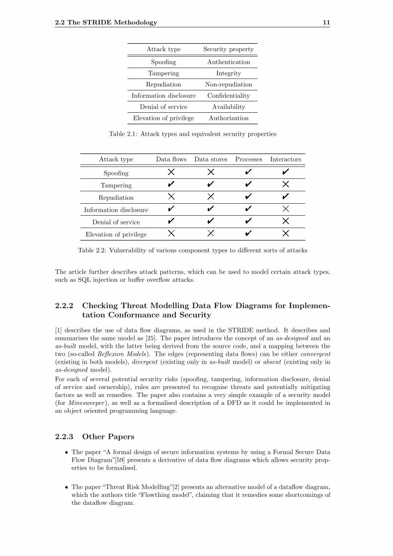
The article then goes on to introduce a set of security properties, then a set of security threatsand attacks against which they protect the system - the name STRIDE is derived from the firstletters of the attack types, as seen in Table 2.1.
The article then continues on to Data Flow Diagrams (DFDs), which are a graphical represen-tation of the data flow in a program. The diagrams model data flows, data stores, processes,interactors and trust boundaries. Data flows represent, for instance, network connections, whiledata stores may represent a database table. Interactors represent data producers and consumers“outside” the system, including the end user, and trust boundaries separate differing levels oftrust. Each of the components is vulnerable to attacks as described in Table 2.2.
10
2.2 The STRIDE Methodology 11
Attack type Security property
Spoofing Authentication
Tampering Integrity
Repudiation Non-repudiation
Information disclosure Confidentiality
Denial of service Availability
Elevation of privilege Authorization
Table 2.1: Attack types and equivalent security properties
Attack type Data flows Data stores Processes Interactors
Spoofing # # " "
Tampering " " " #
Repudiation # # " "
Information disclosure " " " #
Denial of service " " " #
Elevation of privilege # # " #
Table 2.2: Vulnerability of various component types to different sorts of attacks
The article further describes attack patterns, which can be used to model certain attack types,such as SQL injection or buffer overflow attacks.
2.2.2 Checking Threat Modelling Data Flow Diagrams for Implemen-tation Conformance and Security
[1] describes the use of data flow diagrams, as used in the STRIDE method. It describes andsummarises the same model as [25]. The paper introduces the concept of an as-designed and anas-built model, with the latter being derived from the source code, and a mapping between thetwo (so-called Reflexion Models). The edges (representing data flows) can be either convergent(existing in both models), divergent (existing only in as-built model) or absent (existing only inas-designed model).
For each of several potential security risks (spoofing, tampering, information disclosure, denialof service and ownership), rules are presented to recognise threats and potentially mitigatingfactors as well as remedies. The paper also contains a very simple example of a security model(for Minesweeper), as well as a formalised description of a DFD as it could be implemented inan object oriented programming language.
2.2.3 Other Papers
� The paper “A formal design of secure information systems by using a Formal Secure DataFlow Diagram”[59] presents a derivative of data flow diagrams which allows security prop-erties to be formalised.
� The paper “Threat Risk Modelling”[2] presents an alternative model of a dataflow diagram,which the authors title “Flowthing model”, claiming that it remedies some shortcomings ofthe dataflow diagram.
12 Methodology
2.3 Attack Trees
2.3.1 Threat Modelling Using Attack Trees
[51], published in 2008, describes the use of attack trees in the security review of MyProxy[43],which is a credential management system used in grid computer applications. Their usage ofattack tree is canonical - the same model as described by Bruce Schneier - with the aid of asoftware product called SecurITree[3], which provides graphical display of the attack tree as wellas mathematical modelling. The described method for constructing the attack tree is as follows:
1. Define the attack objective, which becomes the root node.
2. Recursively divide this objective into prerequisite objectives.
3. This can be continued to arbitrary detail, but in general the idea is to decompose the attackinto elements that we can quantitatively analyse, e.g. how hard is it to break a 2048 bitRS key?
4. Once we have reached the leaf nodes, we can then assign them values, for instance cost, ordifficulty of execution.
5. These values are propagated up the tree, allowing one to make various calculations basedon the model.
It must be said that the aim of this project is to understand security risks involved in OpenFlow, not necessarily to quantify them. The danger in quantification is, given that the values ofthe leaf nodes are so uncertain, that the assignment of values would suggest a degree of precisionthat the model simply cannot support. The paper itself notes that attack trees are a high levelmethodology. Finally, constructing the attack tree is not performed in a systematic fashion,therefore it must be considered as a way for describing security issues (but in a systematic way)rather than finding them.
2.3.2 A Structural Framework for Modelling Multi-Stage Network At-tacks
[14] provides an extension of the attack tree model, dividing nodes into top level, state level andevent level ranked from most general to most specific. Furthermore, the concept of explicit andimplicit links is introduced. These allow situations to be modelled where the execution of onenode enables another node, i.e. they model capabilities which are conditional on other attacks.The concept of context sensitive nodes is also introduced; this is so that we can model scenariosin which attacks only work in certain security contexts.
2.3.3 Security Protocol Testing Using Attack Trees
[39] presents an application of attack trees for the analysis of the now-obsolete Wireless Appli-cation Protocol (WAP). The paper includes guidelines on how to construct attack trees - therecommended method is to begin with the ultimate goal of attacking the system, with attackson different security properties (confidentiality, integrity and availability) as the second tier (theroot node is of course an OR node). The next tier is the mechanism exploited by the attacker,and the subsequent levels are the steps required in order to perform the exploit. The main partof the paper is dedicated to the creation of actual attacks from an attack tree using an abstractlanguage which is then transformed into executable code, which also allows attack scripts to bereadily adaptable to other languages.
2.3.4 Other Papers
� The paper “System level Security modelling using Attack trees”[30] presents various exten-sions to the attack tree model, mostly allowing for concurrency (e.g. priority AND gate,see above). Many of these concepts can be realised with just AND and OR gates, however,or are only useful in exceptional circumstances (e.g. a k out of n gate).
2.4 State-based and Other Methodologies 13
� The paper “Vulnerability Assessment of Cybersecurity for SCADA Systems Using AttackTrees”[63] contains a security analysis of SCADA in power distribution networks usingattack trees. The paper quantifies vulnerabilities, with a particular emphasis on passwordpolicies, which are known to be a problem on SCADA systems. The paper also ranksvulnerabilities, with a view to prioritise the ones with the greatest impact.
� The paper “Towards an Enhanced Design Level Security”[19] presents an approach forgenerating state charts from attack trees, similar to [20].
2.4 State-based and Other Methodologies
2.4.1 Capability-Centric Attack Model for Network Security Analysis
[58], published in 2010, deals predominately with the question of how attacker capability canbe modelled. The paper defines capability as a tuple of source, destination and rights. Thecapability can be a network or a host capability. Network capability consists of physical, linkand network access1. Host capability consists of OS, service and data access. In a similar manner,vulnerabilities are described as (from most abstract to most concrete): A concept vulnerability,an instance vulnerability, an exposure vulnerability and an exploiting vulnerability. The firstdefines a set of conditions that must be met in order to compromise a system, the second, theappearance of these conditions on a particular system, the third, the capability of an attacker toexploit an instance vulnerability, and the fourth the actual execution of an attack against such avulnerability. In general, the successful exploitation of a vulnerability produces new knowledgeand capabilities which can be, and usually are, used for further attacks on the system. If wecompare this to the attack tree model, here we are looking at capabilities as leaf nodes, theexploitation of which allows us to obtain the capabilities and/or knowledge of the parent nodes.This would continue until we achieve some final objective, which is represented by the root node.
2.4.2 Modelling Security Attacks with Statecharts
[20] describes another method for security analysis, making use of state charts. The authorsdescribe this approach as complementary to the use of attack trees. The paper describes severalalternate methods, including attack nets (based on Petri nets) and the extension of UML forsecurity modelling. The state chart model is attack-centric, modelling attacks with states, statetransitions and events, which trigger the state transitions. The model contains AND as wellas OR gates (in common with attack trees), but also has priority AND gates, which allow asequence of events to be modelled. The AND gates are modelled as sets of states, where eachinput has two states (either “on” or “off”) and there is a set of states which allows the met inputstates to be counted. The OR gates are similar, but of course only require one input state to be“on”. The priority AND gate is similar to the AND gate, but requires that the events occur in agiven order. In summary, it may be said that this paper maps the semantics of an attack treeto those of a finite state machine, adding timing properties to the model. It allows a more lowlevel view of an attack and furthermore enables the numerous tools for simulating finite statemachines to be utilised.
2.4.3 A Decade of Model-Driven Security
[5] as well as a number of other papers[6, 7] describe the approach of model driven security. Thegeneral idea of the usage of a system model to verify security is very much applicable to thisthesis. However, it is important to note that we have no interest in describing policy (that is upto the system administrator) as opposed to the method of implementing (via the installation offlow rules) policy, nor do we have any interest in automated generation of operational systems(in the form of program code, hardware designs or other functional components) from systemmodels. The papers deal in part with role based access control , which is again a question ofpolicy, rather than implementation.Finally, the paper [6] describes the use of process modelling in a security context. This is anapplication of control flow modelling, as opposed to data flow modelling (2.3.1), and is comparable
1This is clearly based on the OSI layered network model.
14 Methodology
with the approaches involving state diagrams (2.4.2). This form of modelling can not readilybe applied to OpenFlow, however. Although OpenFlow defines an API, that is, a series ofmessages that can passed between the the switch and the controller, it does not require any sortof sequential behaviour: Most of the OpenFlow messages are inherently asynchronous in natureand there is no requirement that either the switch or the controller react to each other’s messagesat all. Moreover, any reaction that does occur will be based upon policy, which in a softwaredefined network may be defined by the administrator, or by third party developers. This is incontrast to a protocol where the reaction of the parties to messages is defined in the specificationitself, such as TCP[50].
2.4.4 Other Papers
� The paper “A Threat Model Driven Approach for Security Testing”[69] introduces an auto-mated modelling system, which allows code to be instrumented and recompiled, then runwith randomly generated test cases, permitting the automated generation of threat modelsbased on UML sequence diagrams.
� The paper “An Attack Modelling Based on Hierarchical Colored Petri Nets”[72] presentsanother method for modelling attacks, based on coloured Petri nets. The Petri net methodis more sophisticated than attack trees, representing concurrency better, but is also not aseasy to understand.
2.5 Conclusion
A number of a approaches to security modelling have been reviewed here. In general, theyapproach the issue from one of two perspectives: Either they attempt to model the attacks on asystem, or they attempt to model the system itself, with the intent of finding potential avenuesof attack. The first approach is attack-centric, the second system-centric.For this project, the system-centric approach will be used initially, as the OpenFlow protocolcan be readily described with a data flow diagram (or several). This will allow a better view ofpotential risks and vulnerabilities to be obtained, from which a set of attack trees can be derived.This can be repeated for more complicated attack models, or more complicated setups (multiplecontrollers or switches, use of FlowVisor et al.). Therefore, as the next step, we will:
1. Segment the OpenFlow system into modules.
2. Model these modules with data flow diagrams.
3. Analyse these data flow diagrams for potential attacks.
4. Create attack trees based on the scenarios that we have described in our attack models.
Chapter 3
Analysis of the OpenFlow 1.0Specification
3.1 Introduction
In this chapter, the OpenFlow 1.0 specification will be subjected to a security analysis accordingto the STRIDE methodology[25]. First, a description of the OpenFlow 1.0 specification willbe presented, followed by a data flow diagram modelling the data flows inside the OpenFlowcontroller/switch system. This model will be analysed for vulnerabilities using the STRIDEmethod. Finally, these vulnerabilities and their exploitation will be examined with the use ofattack trees.
3.2 Specification
3.2.1 Data Stores
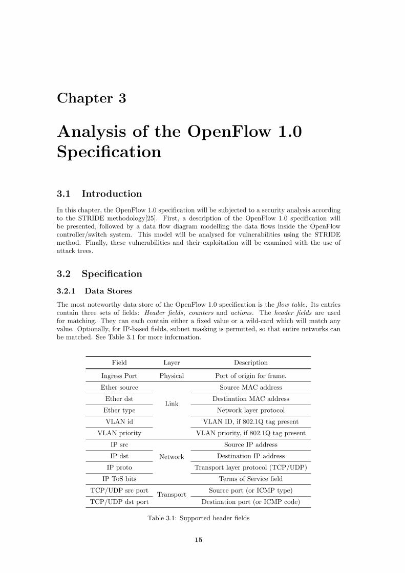
The most noteworthy data store of the OpenFlow 1.0 specification is the flow table. Its entriescontain three sets of fields: Header fields, counters and actions. The header fields are usedfor matching. They can each contain either a fixed value or a wild-card which will match anyvalue. Optionally, for IP-based fields, subnet masking is permitted, so that entire networks canbe matched. See Table 3.1 for more information.
Field Layer Description
Ingress Port Physical Port of origin for frame.
Ether source
Link
Source MAC address
Ether dst Destination MAC address
Ether type Network layer protocol
VLAN id VLAN ID, if 802.1Q tag present
VLAN priority VLAN priority, if 802.1Q tag present
IP src
Network
Source IP address
IP dst Destination IP address
IP proto Transport layer protocol (TCP/UDP)
IP ToS bits Terms of Service field
TCP/UDP src portTransport
Source port (or ICMP type)
TCP/UDP dst port Destination port (or ICMP code)
Table 3.1: Supported header fields
15
16 Analysis of the OpenFlow 1.0 Specification
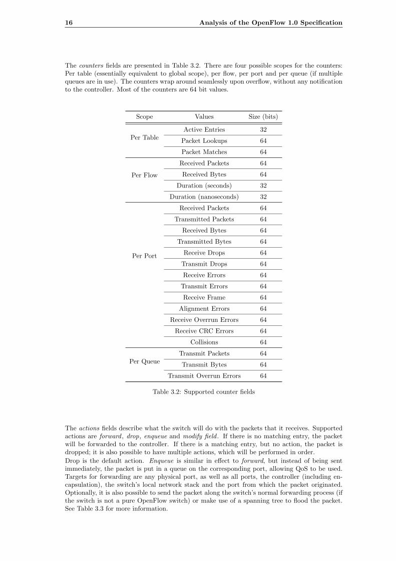
The counters fields are presented in Table 3.2. There are four possible scopes for the counters:Per table (essentially equivalent to global scope), per flow, per port and per queue (if multiplequeues are in use). The counters wrap around seamlessly upon overflow, without any notificationto the controller. Most of the counters are 64 bit values.
Scope Values Size (bits)
Per TableActive Entries 32
Packet Lookups 64
Packet Matches 64
Per Flow
Received Packets 64
Received Bytes 64
Duration (seconds) 32
Duration (nanoseconds) 32
Per Port
Received Packets 64
Transmitted Packets 64
Received Bytes 64
Transmitted Bytes 64
Receive Drops 64
Transmit Drops 64
Receive Errors 64
Transmit Errors 64
Receive Frame 64
Alignment Errors 64
Receive Overrun Errors 64
Receive CRC Errors 64
Collisions 64
Per QueueTransmit Packets 64
Transmit Bytes 64
Transmit Overrun Errors 64
Table 3.2: Supported counter fields
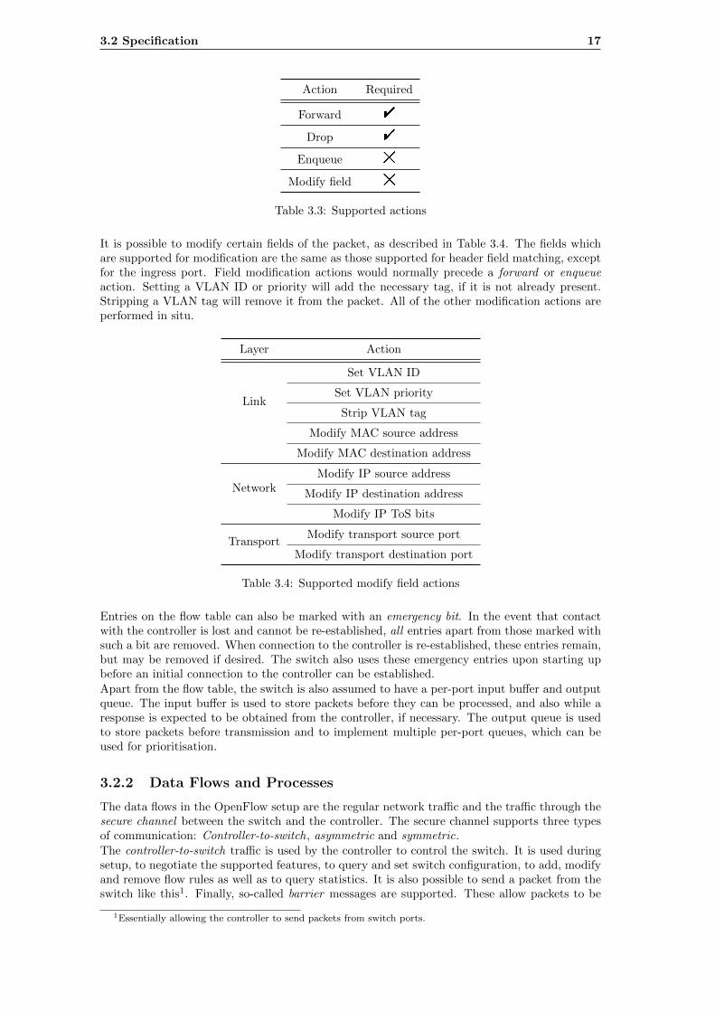
The actions fields describe what the switch will do with the packets that it receives. Supportedactions are forward , drop, enqueue and modify field . If there is no matching entry, the packetwill be forwarded to the controller. If there is a matching entry, but no action, the packet isdropped; it is also possible to have multiple actions, which will be performed in order.
Drop is the default action. Enqueue is similar in effect to forward, but instead of being sentimmediately, the packet is put in a queue on the corresponding port, allowing QoS to be used.Targets for forwarding are any physical port, as well as all ports, the controller (including en-capsulation), the switch’s local network stack and the port from which the packet originated.Optionally, it is also possible to send the packet along the switch’s normal forwarding process (ifthe switch is not a pure OpenFlow switch) or make use of a spanning tree to flood the packet.See Table 3.3 for more information.
3.2 Specification 17
Action Required
Forward "
Drop "
Enqueue #
Modify field #
Table 3.3: Supported actions
It is possible to modify certain fields of the packet, as described in Table 3.4. The fields whichare supported for modification are the same as those supported for header field matching, exceptfor the ingress port. Field modification actions would normally precede a forward or enqueueaction. Setting a VLAN ID or priority will add the necessary tag, if it is not already present.Stripping a VLAN tag will remove it from the packet. All of the other modification actions areperformed in situ.
Layer Action
Link
Set VLAN ID
Set VLAN priority
Strip VLAN tag
Modify MAC source address
Modify MAC destination address
NetworkModify IP source address
Modify IP destination address
Modify IP ToS bits
TransportModify transport source port
Modify transport destination port
Table 3.4: Supported modify field actions
Entries on the flow table can also be marked with an emergency bit. In the event that contactwith the controller is lost and cannot be re-established, all entries apart from those marked withsuch a bit are removed. When connection to the controller is re-established, these entries remain,but may be removed if desired. The switch also uses these emergency entries upon starting upbefore an initial connection to the controller can be established.
Apart from the flow table, the switch is also assumed to have a per-port input buffer and outputqueue. The input buffer is used to store packets before they can be processed, and also while aresponse is expected to be obtained from the controller, if necessary. The output queue is usedto store packets before transmission and to implement multiple per-port queues, which can beused for prioritisation.
3.2.2 Data Flows and Processes
The data flows in the OpenFlow setup are the regular network traffic and the traffic through thesecure channel between the switch and the controller. The secure channel supports three typesof communication: Controller-to-switch, asymmetric and symmetric.
The controller-to-switch traffic is used by the controller to control the switch. It is used duringsetup, to negotiate the supported features, to query and set switch configuration, to add, modifyand remove flow rules as well as to query statistics. It is also possible to send a packet from theswitch like this1. Finally, so-called barrier messages are supported. These allow packets to be
1Essentially allowing the controller to send packets from switch ports.
18 Analysis of the OpenFlow 1.0 Specification
handled in a defined order: All packets received prior to the barrier message are guaranteed tobe processed prior to any received afterwards.The asymmetric messages cover the forwarding of messages to the controller - normally onlythe first 128 bytes in a packet in message2 - the removal of flow rules (even when this has beeninitiated by the controller), changes in port status and errors. Packets whose headers are sentto the controller are accompanied with a buffer ID, which can be used to transmit the storedpacket from the switch’s input buffer.The symmetric messages include hello messages, for connection instantiation, echo messagesto determine liveness as well as the performance of the control connection, and finally vendorspecific messages, which allow extensions to OpenFlow to be implemented.
3.3 Data Flow Model
3.3.1 Summary
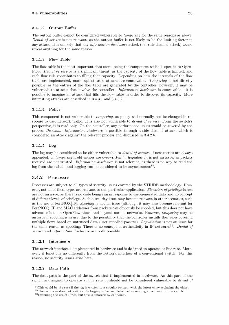
Here, we model a simple scenario, namely the processing of packets, which may or may notcreate a new entry in the flow table. We assume OpenFlow 1.0 with no extensions on a routerwhich is OpenFlow-only (no fallback to conventional switching). The model consists of twoclients, independent from the system, identical and not trusted, a switch and a controller. Theclients are each connected to an interface of the switch, while the controller is connected to amanagement interface.Input packets to the switch are buffered, then processed by the switch’s data path: Dependingon the flow table, they may be forwarded or enqueued to an interface-specific queue before beingsent through the attached interface, modified, sent to the controller or dropped. Packets with noflow table entry are forwarded to the controller, those with an entry but no action are dropped.Packets associated with multiple actions have all actions carried out in order. Modified packetsare modified in-place (in the input buffer of the interface on which they were received), and thenare subject to further actions, as specified by the flow table. It is possible to enqueue packetsinstead of forwarding them, allowing quality of service control to be used. The flow table containsa set of counters per-flow, as well as per-port and per-table. These are updated on execution ofan action, and can be obtained by the controller. The controller may also have a packet sent outof an interface and install new flow rules.The controller communicates with the switch via a network interface. It receives asynchronousmessages from the switch, notifying it of new flows. It may react by installing a flow rule, orjust having the packet forwarded, depending on a policy. The controller keeps a log, which maycontain new flows established, as well as counter values that have been obtained from the switch.The log may be read, and the policy altered, by a system administrator, who may interact withthe controller through an administrative interface. Note that although these components of thecontroller may be considered typical, they are not part of the OpenFlow specification, in whichthe controller can be considered a black box. Therefore, specific security issues arising inside thecontroller will not be given any further consideration. For more information about the switchimplementation, see [41]. Please see A.1 on page 82 for more information on how data flowdiagrams are to be interpreted.
3.3.2 Interactors
Client n This represents a client, considered external to the system and not trustworthy.
Administrator The system administrator, who may interact with the controller.
3.3.3 Data Stores
Input buffer n Where incoming packets are stored before and during processing. This bufferis specific to interface n.
Output buffer n Where outgoing packets are stored after forwarding to client n, if the enqueueor forward action is used.
2However, if the buffer is full, the entire packet should be sent.
3.3 Data Flow Model 19
Flow table This is the switch’s flow table, as described in the OpenFlow specification. It hascolumns for matching layer 2, 3 and 4 headers, one or more actions and several counters.
Policy This models the rules by which the controller will decide how to react to a new flow. Itmay be altered only by an administrator.
Log This represents a log maintained on the controller.
3.3.4 Processes
Switch This process models the switch as a whole.
Controller This process models the controller as a whole.
Interface n This models the network interface connected to client n.
Data path This represents the data path of the controller. This is essentially the part of a switchthat is implemented in hardware3, and is independent of the operation of OpenFlow.
OpenFlow Module This represents the implementation-dependent OpenFlow software4 on theswitch, which is responsible for managing the flow table, as well as performing actions whichare not supported by the data path.
Secure Channel This process models the network interface of the switch facing the controller,including SSL encryption, if it is in use.
OpenFlow Interface This process models standardised part of the controller software and theinterface of the controller with the switch, including SSL encryption.
Decision This represents the “user-implemented” part of the OpenFlow controller. It is respon-sible for applying and enforcing forwarding policy and installing and removing flow rulesas needed.
Administration Interface This represents an interface (e.g. web interface, CLI) via which anadministrator may interact with the controller.
3.3.5 Data Flows
Sent packet to n This represents the transmission of a packet to client n.
Received packet from n This represents the reception of a packet from client n.
Controller-to-switch message This represents the sending of a controller-to-switch message,as defined in Appendix A of the OpenFlow specification, from the controller to the switchin order to send a packet, add a new flow table entry or query counters.
Asynchronous message This represents the sending of an asynchronous message, as definedin Appendix A of the OpenFlow specification, from the switch to the controller in order tonotify of a received packet, port changes or errors5.
Received packet A packet that is received from a network interface and copied into the inputbuffer.
Transmitted packet A packet that is forwarded from a queue, as a result of the enqueue orthe forward action.
Forwarded/Enqueued packet A packet that is stored in a per-interface queue, as a result ofthe enqueue or the forward action.
Packet to process A packet which is read from the input buffer in order to be processed bythe data path.
3This does not apply to a switch implemented purely in software.4Here software also includes firmware.5Note that this model does not include synchronous messages, also defined in Appendix A of the OpenFlow
specification.

20 Analysis of the OpenFlow 1.0 Specification
Remove/modify packet The packet remains in the input buffer until it is forwarded ordropped. The modify action results in the packet being changed in-place in the inputbuffer.
Transmit packet The controller can send a packet directly through the data path6.
Packet sample If a new flow is encountered, a sample of the packet is sent to the controllerto allow it to decide how to react. Normally, only the header is sent (by default 128bytes), although in some circumstances the entire packet may be sent7. This data flow alsorepresents the transition between the data plane and the control plane of the switch, asoperations not supported by the data path will result in packets being forwarded to thesoftware.
Read flow table Entries from the flow table are used by the data path, and can also be readout by the controller via the OpenFlow software.
Update counter The data path will update the counters in the matching flow table entryautomatically.
Modify flow table New entries in the flow table are installed, existing entries are modifiedor old entries are removed in response to a flow modification message8 generated by thecontroller. The OpenFlow software removes entries by itself when they reach their hard9
or soft10 timeout.
Get state/event The controller can query the state of the switch (e.g. the flow table) and isinformed of events, such as the start of a new flow11.
Set state/action The controller can modify the state of the switch (e.g. the flow table) and itperforms actions, such as sending a packet12.
Write log The logging process should regularly store logged events in a logfile.
Read log It is assumed that it is possible for the administrator to inspect the log via an ad-ministrative interface.
Read policy/write policy The administrative interface should also allow the forwarding pol-icy of the controller to be modified.
Get policy In order to decide how to react to a packet received, the policy of the controllershould be read first.
Get/set configuration The administrative interface should be able to set the configuration ofthe switch via the OpenFlow interface.
Set value/get value This represents the administrator’s interaction with the administrativeinterface.
3.3.6 Boundaries
The system contains both machine boundaries and trust boundaries. The machine boundariesare placed between the clients and the switch, as well as between the switch and the controller.The only trust boundary runs between the data path (which belongs to the untrusted part ofthe switch) and the OpenFlow Module and flow table (belonging to the trusted part). The datapath clearly deals with untrusted data, and is not capable of writing to the flow table, except forupdating counters. The flow table is clearly trusted, as it controls the operation of the switch.By extension, the OpenFlow Module, which manages the flow table, must also be trusted.
6With the use of an ofp packet out message.7This is the case if the input buffer is full and it is unable to store any new packets.8That is, ofp flow mod.9The duration after which the flow rule will be removed in all cases.
10The maximum idle duration permitted before the flow rule is removed.11With the ofp packet in message.12With the ofp packet out message.
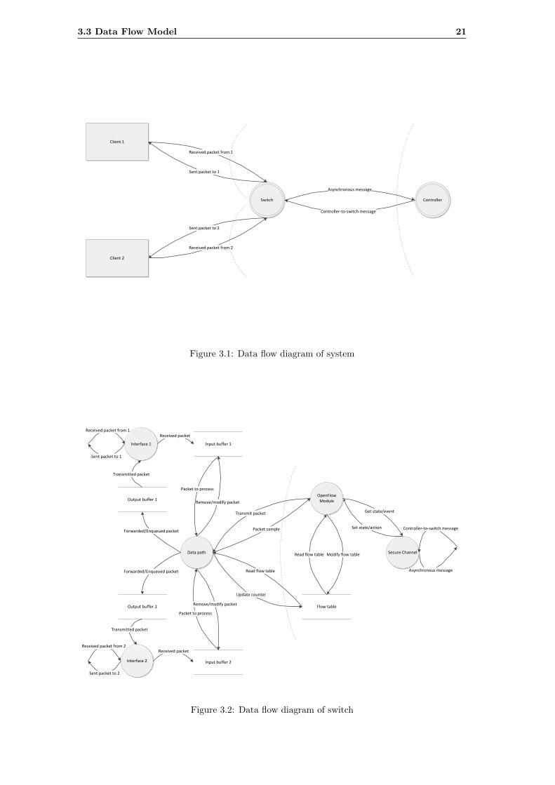
3.3 Data Flow Model 21
Client 1
Switch Controller
Received packet from 1
Sent packet to 1
Sent packet to 2
Received packet from 2
Asynchronous message
Controller-to-switch message
Client 2
Figure 3.1: Data flow diagram of system
Asynchronous message
Input buffer 1
Secure ChannelData path
Packet to process
Flow table
Read flow table
Update counter
Set state/actionPacket sample
Read flow table
Interface 1
Received packet
Interface 2
Transmitted packet
Output buffer 2
Forwarded/Enqueued packet
Output buffer 1
Forwarded/Enqueued packet
Transmitted packet
Remove/modify packet
Input buffer 2
Received packet
Packet to process
OpenFlow Module
Transmit packet
Modify flow table
Get state/event
Received packet from 1
Sent packet to 1
Sent packet to 2
Received packet from 2
Controller-to-switch message
Remove/modify packet
Figure 3.2: Data flow diagram of switch
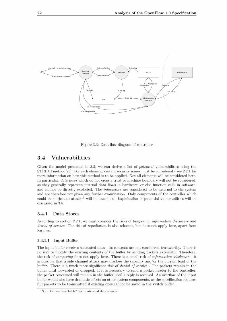
22 Analysis of the OpenFlow 1.0 Specification
Asynchronous message
Controller-to-switch message
OpenFlow Interface
Policy
Administration interface
Write policyRead policy
Administrator
Get value
Decision
Get state/event
Set state/action Get policy
Log
Write log
Read log
Write log
Set configuration
Get configuration
Set value
Figure 3.3: Data flow diagram of controller
3.4 Vulnerabilities
Given the model presented in 3.3, we can derive a list of potential vulnerabilities using theSTRIDE method[25]. For each element, certain security issues must be considered - see 2.2.1 formore information on how this method is to be applied. Not all elements will be considered here.In particular, data flows which do not cross a trust or machine boundary will not be considered,as they generally represent internal data flows in hardware, or else function calls in software,and cannot be directly exploited. The interactors are considered to be external to the systemand are therefore not given any further examination. Only components of the controller whichcould be subject to attack13 will be examined. Exploitation of potential vulnerabilities will bediscussed in 3.5.
3.4.1 Data Stores
According to section 2.2.1, we must consider the risks of tampering, information disclosure anddenial of service. The risk of repudiation is also relevant, but does not apply here, apart fromlog files.
3.4.1.1 Input Buffer
The input buffer receives untrusted data - its contents are not considered trustworthy. There isno way to modify the existing contents of the buffer by sending packets externally. Therefore,the risk of tampering does not apply here. There is a small risk of information disclosure - itis possible that a side channel attack may disclose the capacity and/or the current load of thebuffer. There is a much more significant risk of denial of service - The packets remain in thebuffer until forwarded or dropped. If it is necessary to send a packet header to the controller,the packet concerned will remain in the buffer until a reply is received. An overflow of the inputbuffer would also have dramatic effects on other system components, as the specification requiresfull packets to be transmitted if existing ones cannot be saved in the switch buffer.
13i.e. that are “reachable” from untrusted data sources.
3.4 Vulnerabilities 23
3.4.1.2 Output Buffer
The output buffer cannot be considered vulnerable to tampering for the same reasons as above.Denial of service is not relevant, as the output buffer is not likely to be the limiting factor inany attack. It is unlikely that any information disclosure attack (i.e. side channel attack) wouldreveal anything for the same reason.
3.4.1.3 Flow Table
The flow table is the most important data store, being the component which is specific to Open-Flow. Denial of service is a significant threat, as the capacity of the flow table is limited, andeach flow rule contributes to filling that capacity. Depending on how the internals of the flowtable are implemented, more sophisticated attacks are conceivable. Tampering is not directlypossible, as the entries of the flow table are generated by the controller, however, it may bevulnerable to attacks that involve the controller. Information disclosure is conceivable - it ispossible to imagine an attack that fills the flow table in order to discover its capacity. Moreinteresting attacks are described in 3.4.3.1 and 3.4.3.2.
3.4.1.4 Policy
This component is not vulnerable to tampering, as policy will normally not be changed in re-sponse to user network traffic. It is also not vulnerable to denial of service: From the switch’sperspective, it is read-only. On the controller, any performance issues would be covered by theprocess Decision. Information disclosure is possible through a side channel attack, which isconsidered an attack against the relevant process and discussed in 3.4.2.6.
3.4.1.5 Log
The log may be considered to be either vulnerable to denial of service, if new entries are alwaysappended, or tampering if old entries are overwritten14. Repudiation is not an issue, as packetsreceived are not trusted. Information disclosure is not relevant, as there is no way to read thelog from the switch, and logging can be considered to be asynchronous15.
3.4.2 Processes
Processes are subject to all types of security issues covered by the STRIDE methodology. How-ever, not all of these types are relevant to this particular application. Elevation of privilege issuesare not an issue, as there is no code being run in response to user-generated data and no conceptof different levels of privilege. Such a security issue may become relevant in other scenarios, suchas the use of FortNOX[49]. Spoofing is not an issue (although it may also become relevant forFortNOX): IP and MAC addresses from packets can obviously be spoofed, but this does not haveadverse effects on OpenFlow above and beyond normal networks. However, tampering may bean issue if spoofing is in use, due to the possibility that the controller installs flow rules coveringmultiple flows based on untrusted data (user supplied packets). Repudiation is not an issue forthe same reason as spoofing: There is no concept of authenticity in IP networks16. Denial ofservice and information disclosure are both possible.
3.4.2.1 Interface n
The network interface is implemented in hardware and is designed to operate at line rate. More-over, it functions no differently from the network interface of a conventional switch. For thisreason, no security issues arise here.
3.4.2.2 Data Path
The data path is the part of the switch that is implemented in hardware. As this part of theswitch is designed to operate at line rate, it should not be considered vulnerable to denial of
14This could be the case if the log is written in a circular pattern, with the latest entry replacing the oldest.15The controller does not wait for the logging to be completed before sending a command to the switch.16Excluding the use of IPSec, but this is enforced by endpoints.
24 Analysis of the OpenFlow 1.0 Specification
service attacks. If the switch is incapable of processing packets at line rate, then its designmust be considered flawed. As the data path is assumed to process packets at the same speedindependently of their contents, information disclosure is not possible. Tampering is not possible,as the data path simply follows the instructions in the flow table. Any attack would thereforebe based on flow rules being installed in the flow table by the controller.
3.4.2.3 OpenFlow Module
This is the part of the switch that is implemented in software. Insofar as the data path ofthe switch does not support OpenFlow operations, these must be implemented on the switchsoftware instead. This may result in denial of service attacks. Side channel attacks based onsuch performance differences are described in 3.4.3.1. Tampering attacks are not possible herefor the same reason as 3.4.2.2.
3.4.2.4 Secure Channel
The secure channel operates an encrypted channel over SSL. This requires a certain amount ofprocessing power, unless the encryption is performed in hardware. If it is possible to obtainaccess to the management network, it is also possible to attack the interface with a varietyof conventional TCP/IP attacks. This component is therefore vulnerable to denial of serviceattacks. Due to strong encryption being used, we can be reasonably sure that tampering andinformation disclosure are not possible, but see also 3.4.3.3.
3.4.2.5 OpenFlow Interface
This component represents the counterpart to the secure channel (3.4.2.4) in the controller. Ithas the same vulnerabilities. It is likely that the controller has more processing power than theswitch, but the likelihood of the controller having encryption performed in hardware is lower.The controller is more vulnerable to denial of service attacks if it controls multiple switchesconcurrently, which is not represented in the situation modelled here, but is the most likelyscenario in practice.
3.4.2.6 Decision
The decision module is where the “user” of the system implements the control logic. This maybe implemented using Python or another scripting language. At any rate, this logic may bevulnerable to denial of service attacks if new flows are generated at a high rate. A “smart”controller may implement flow rule aggregation, such that several flow rules are aggregated intoone flow rule using wildcards and subnet masks, instead of simply reactively installing flow rulesto match single flows. If such a system is in use, then the logic is also vulnerable to tampering,as user-generated, untrusted content is being used to install flow rules which have an effect onother users or systems. The logic may also be vulnerable to information disclosure, in order todetermine whether flow rules are being installed or not. This is described in 3.4.3.3.
3.4.2.7 Administration Interface
The administration interface of the controller, assuming that it has one (a simple system mighthave its configuration hard coded), is a potential avenue for attacking the system. It is notpart of the OpenFlow specification and therefore is not covered in this thesis, although anycomprehensive audit of a working system must include all elements.
3.4.3 Data Flows
Only data flows that cross process, machine or trust boundaries will be considered here. Thepurpose of this is to reduce the number of irrelevant elements requiring consideration.
3.4.3.1 Packet Sample
This data flow represents the transition between the hardware and software components of theswitch, assuming that the entire switch is not implemented in software. As the software compo-nents are less optimised for processing packets at line rates, operations which are not supported
3.5 Attack Trees 25
by the switch’s data path are significantly slower. This represents a denial of service vulnerabil-ity (described in 3.4.2.3), but also an information disclosure vulnerability: It may be possible toexploit the timing differences to learn what operations a switch is performing on a packet. Thiswill require accurate timing information and a large data set, unlike 3.4.3.3. Tampering is nota concern due to the fact that this is an internal data connection with no possibility of outsideinterference.
3.4.3.2 Update Counter
This data flow represents the special case where the flow table is written by the data path, namelyto update counters. This represents a risk of tampering, as the counter values could be forced tooverflow. There is no overflow notification in the OpenFlow 1.0 protocol, so this would falsify thevalues, although this is likely to be very difficult in practice due to the range of the counters17.It is also conceivable that, with the use of forged values in the packet header, counters of otherflows may be influenced, which may constitute a security issue, depending on how they are used.There is no possibility of denial of service or information disclosure, as the update happens atline rate and an overflow does not impact performance or otherwise cause disruption.
3.4.3.3 Asynchronous Message
This data flow represents the actual transmission of data from the switch to the controller. Itis unique to the OpenFlow setup and from a security perspective one of the most problematicelements. Tampering is not possible due to the use of SSL. Denial of service is possible: Therate of traffic to the controller is proportional to the number of packets that do not matchexisting flow rules. If the network capacity is exceeded and the network becomes congested,the switch’s reaction to new flows will be adversely affected. Since there is a substantial timedifference between packets processed locally on the switch and those that must be transmittedto the controller, it is possible to determine whether or not this transmission has taken place.This leads to information disclosure, making it possible to determine whether a packet matchesa flow rule or not. With subsequent sending of additional packets, it may also be determined ifa new flow rule is installed, as well as the duration of the flow rule. Additional issues arise ifan attacker is assumed to have direct access to the management network. In this case, trafficanalysis can be performed on the transmissions between the switch and the controller. Thiswould reveal more information than can be obtained via timing analysis, as it is also possible todetermine the size of any transmitted packets, as well as the controller’s response. With accessto the management network, it is also possible to use various conventional TCP/IP attacks todisrupt the switch-controller connection, resulting in additional possibilities for denial of serviceattacks.
3.5 Attack Trees
3.5.1 Introduction
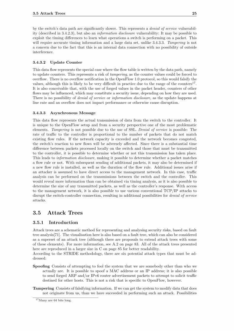
Attack trees are a schematic method for representing and analysing security risks, based on faulttree analysis[71]. The visualisation here is also based on a fault tree, which can also be consideredas a superset of an attack tree (although there are proposals to extend attack trees with someof these elements). For more information, see A.2 on page 83. All of the attack trees presentedhere are reproduced in a larger size in C on page 85 for better readability.According to the STRIDE methodology, there are six potential attack types that must be ad-dressed:
Spoofing Consists of attempting to fool the system that we are somebody other than who weactually are. It is possible to spoof a MAC address or an IP address; it is also possibleto send forged ARP and/or IPv6 router advertisement packets to attempt to solicit trafficdestined for other hosts. This is not a risk that is specific to OpenFlow, however.
Tampering Consists of falsifying information. If we can get the system to modify data that doesnot originate from us, than we have succeeded in performing such an attack. Possibilities
17Many are 64 bits long.
26 Analysis of the OpenFlow 1.0 Specification
here are the falsification of flow counters, and tricking the controller into the installationof flow rules which may perform some packet modification.
Repudiation Consists of denying responsibility for content generated by us. As stated above,we may forge source addresses for packets, therefore there is no assumption that packetsgenuinely originate where the packet headers indicate.
Information disclosure Consists of obtaining information that we are not entitled to see. Inthis context, this applies mostly to side channel attacks to reveal more information aboutthe OpenFlow system as a whole than would be available if a regular switch was beingused.
Denial of service Consists of preventing the system from transmitting information normally.This is the security risk where OpenFlow provides the largest attack surface: The fact thatpackets must be sent to the controller on a regular basis opens up a number of potentialavenues for denial of service attacks.
Elevation of privilege Consists of obtaining the ability to perform operations that we are notentitled to perform. The only potential way we could do this is by assuming control overthe controller, which is assumed to be infeasible due to the use of SSL. This may becomerelevant when considering more complicated variants of OpenFlow systems, such as thosewhere multiple authorities are permitted to inject flow rules into the system.
Attack OpenFlow
Information disclosure
TamperingDenial of service
Figure 3.4: Overview attack tree
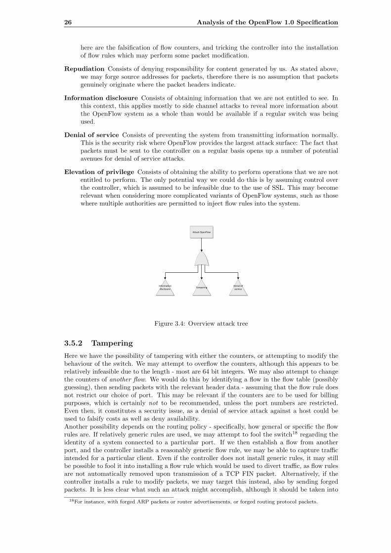
3.5.2 Tampering
Here we have the possibility of tampering with either the counters, or attempting to modify thebehaviour of the switch. We may attempt to overflow the counters, although this appears to berelatively infeasible due to the length - most are 64 bit integers. We may also attempt to changethe counters of another flow. We would do this by identifying a flow in the flow table (possiblyguessing), then sending packets with the relevant header data - assuming that the flow rule doesnot restrict our choice of port. This may be relevant if the counters are to be used for billingpurposes, which is certainly not to be recommended, unless the port numbers are restricted.Even then, it constitutes a security issue, as a denial of service attack against a host could beused to falsify costs as well as deny availability.Another possibility depends on the routing policy - specifically, how general or specific the flowrules are. If relatively generic rules are used, we may attempt to fool the switch18 regarding theidentity of a system connected to a particular port. If we then establish a flow from anotherport, and the controller installs a reasonably generic flow rule, we may be able to capture trafficintended for a particular client. Even if the controller does not install generic rules, it may stillbe possible to fool it into installing a flow rule which would be used to divert traffic, as flow rulesare not automatically removed upon transmission of a TCP FIN packet. Alternatively, if thecontroller installs a rule to modify packets, we may target this instead, also by sending forgedpackets. It is less clear what such an attack might accomplish, although it should be taken into
18For instance, with forged ARP packets or router advertisements, or forged routing protocol packets.
3.5 Attack Trees 27
consideration if, for instance, the packet contents are being used to add a VLAN tag, or QoSdata.
Tampering
Against switch
Overflow counters
Attack flow aggregation
Against controller
Alter different counter
Send packet out of another port
Modify packet
Generate sustained
extremely high traffic load
Determine parameters of target flow or
table
Generate packet flow
with appropriately forged values
Send falsified ARP or LLDP or routing packets
to redirect traffic
Send forged packets to establish
aggregated flow rule
Identify which of these flow rules result in
packet modification
Identify which flow rules are created with
wildcards
Identify which flow rules are created with
wildcards
Send forged packets to establish
aggregated flow rule
Against counter update
Against Decision process
Figure 3.5: Tampering attack tree
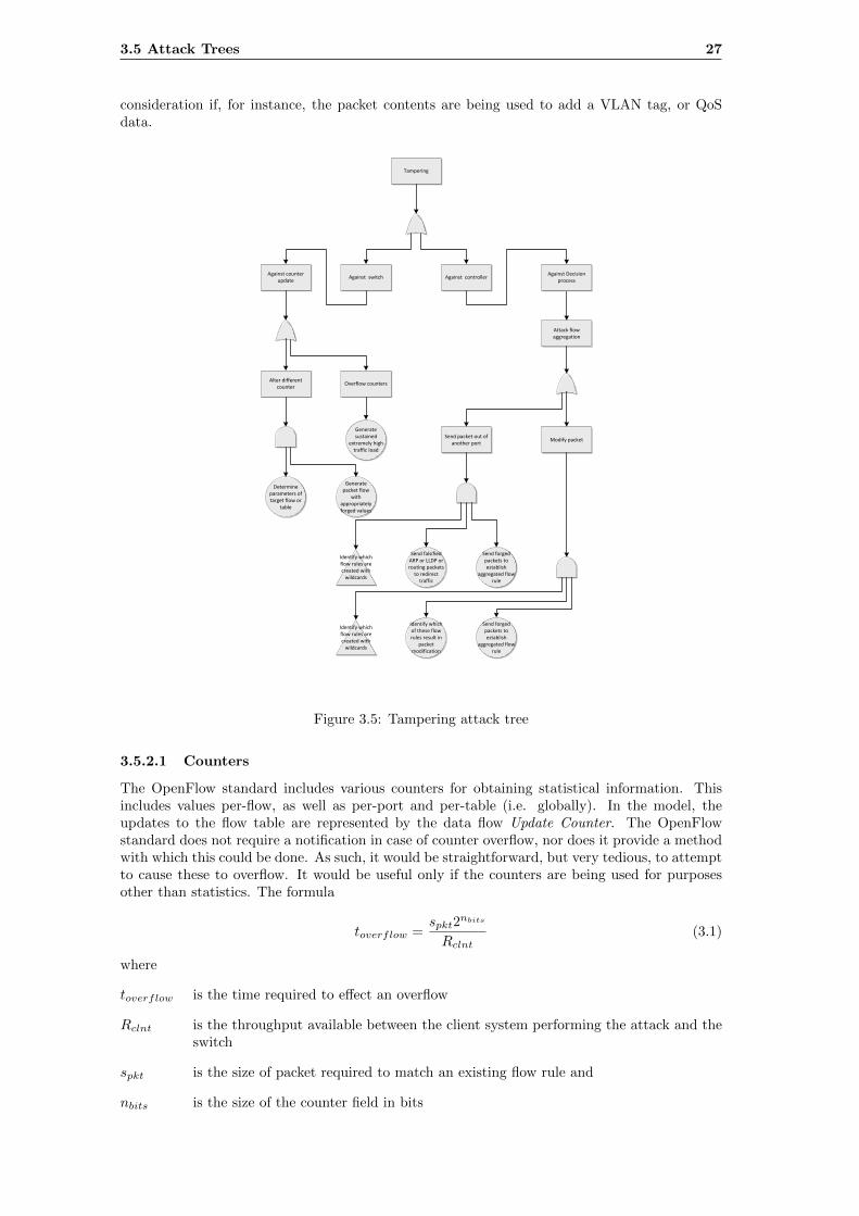
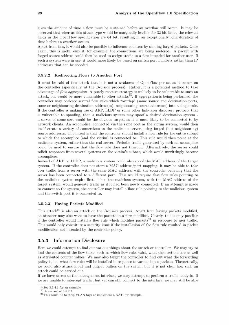
3.5.2.1 Counters
The OpenFlow standard includes various counters for obtaining statistical information. Thisincludes values per-flow, as well as per-port and per-table (i.e. globally). In the model, theupdates to the flow table are represented by the data flow Update Counter. The OpenFlowstandard does not require a notification in case of counter overflow, nor does it provide a methodwith which this could be done. As such, it would be straightforward, but very tedious, to attemptto cause these to overflow. It would be useful only if the counters are being used for purposesother than statistics. The formula
toverflow =spkt2
nbits
Rclnt(3.1)
where
toverflow is the time required to effect an overflow
Rclnt is the throughput available between the client system performing the attack and theswitch
spkt is the size of packet required to match an existing flow rule and
nbits is the size of the counter field in bits
28 Analysis of the OpenFlow 1.0 Specification
gives the amount of time a flow must be sustained before an overflow will occur. It may beobserved that whereas this attack type would be marginally feasible for 32 bit fields, the relevantfields in the OpenFlow specification are 64 bit, resulting in an exceptionally long duration oftime before an overflow occurs.Apart from this, it would also be possible to influence counters by sending forged packets. Onceagain, this is useful only if, for example, the connections are being metered. A packet withforged source address could then be used to assign traffic to a flow intended for another user. Ifsuch a system were in use, it would more likely be based on switch port numbers rather than IPaddresses that can be spoofed.
3.5.2.2 Redirecting Flows to Another Port
It must be said of this attack that it is not a weakness of OpenFlow per se, as it occurs onthe controller (specifically, at the Decision process). Rather, it is a potential method to takeadvantage of flow aggregation. A purely reactive strategy is unlikely to be vulnerable to such anattack, but would be more vulnerable to other attacks19. If aggregation is being performed, thecontroller may coalesce several flow rules which “overlap” (same source and destination ports,same or neighbouring destination address(es), neighbouring source addresses) into a single rule.If the controller is making use of ARP, LLDP or some other link-layer discovery protocol thatis vulnerable to spoofing, then a malicious system may spoof a desired destination system -a server of some sort would be the obvious target, as it is most likely to be connected to bynetwork clients. An accomplice, connected via the same port as the victim system, would thenitself create a variety of connections to the malicious server, using forged (but neighbouring)source addresses. The intent is that the controller should install a flow rule for the entire subnetto which the accomplice (and the victim) is connected to. This rule would then point at themalicious system, rather than the real server. Periodic traffic generated by such an accomplicecould be used to ensure that the flow rule does not timeout. Alternatively, the server couldsolicit responses from several systems on the victim’s subnet, which would unwittingly becomeaccomplices.Instead of ARP or LLDP, a malicious system could also spoof the MAC address of the targetsystem. If the controller does not store a MAC address/port mapping, it may be able to takeover traffic from a server with the same MAC address, with the controller believing that theserver has been connected to a different port. This would require that flow rules pointing tothe malicious system expire first. Then the malicious system, with the MAC address of thetarget system, would generate traffic as if it had been newly connected. If an attempt is madeto connect to the system, the controller may install a flow rule pointing to the malicious systemand the switch port it is connected to.
3.5.2.3 Having Packets Modified
This attack20 is also an attack on the Decision process. Apart from having packets modified,an attacker may also want to have the packets in a flow modified. Clearly, this is only possibleif the controller would install a flow rule which modifies packets21 in response to user traffic.This would only constitute a security issue if the installation of the flow rule resulted in packetmodification not intended by the controller policy.
3.5.3 Information Disclosure
Here we could attempt to find out various things about the switch or controller. We may try tofind the contents of the flow table, such as which flow rules exist, what their actions are as wellas attributed counter values. We may also target the controller to find out what the forwardingpolicy is, i.e. what flow rules will be installed in response to various input packets. Theoretically,we could also attack input and output buffers on the switch, but it is not clear how such anattack could be carried out.If we have access to the management interface, we may attempt to perform a traffic analysis. Ifwe are unable to intercept traffic, but yet can still connect to the interface, we may still be able
19See 3.5.4.1 for an example.20 A variant of 3.5.2.221This could be to strip VLAN tags or implement a NAT, for example.
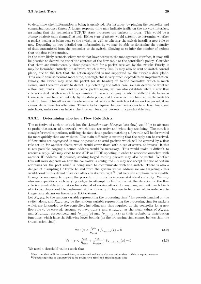
3.5 Attack Trees 29
to determine when information is being transmitted. For instance, by pinging the controller andcomparing response times: A longer response time may indicate traffic on the network interface,assuming that the controller’s TCP/IP stack processes the packets in order. This would be atiming analysis (side channel) attack. Either type of attack would attempt to determine whethera packet header is being sent to the switch, as well as whether the switch installs a new rule ornot. Depending on how detailed our information is, we may be able to determine the quantityof data transmitted from the controller to the switch, allowing us to infer the number of actionsthat the flow rule contains.In the more likely scenario where we do not have access to the management interface, it may stillbe possible to determine either the contents of the flow table or the controller’s policy. Considerthat there are fundamentally three possibilities for a packet received by the switch: Firstly, itmay be forwarded entirely in hardware, which is very fast. It may also be sent to switch controlplane, due to the fact that the action specified is not supported by the switch’s data plane.This would take somewhat more time, although this is very much dependent on implementation.Finally, the switch may send the packet (or its header) on to the controller, which is muchslower, and therefore easier to detect. By detecting the latter case, we can determine whethera flow rule exists. If we send the same packet again, we can also establish when a new flowrule is created. With a much larger number of packets, we may be able to differentiate betweenthose which are handled entirely by the data plane, and those which are handled in the switch’scontrol plane. This allows us to determine what actions the switch is taking on the packet, if wecannot determine this otherwise. These attacks require that we have access to at least two clientinterfaces, unless we can have a client reflect back our packets in a predictable way.
3.5.3.1 Determining whether a Flow Rule Exists
The objective of such an attack (on the Asynchronous Message data flow) would be to attemptto probe that status of a network - which hosts are active and what they are doing. The attack isstraightforward to perform, utilising the fact that a packet matching a flow rule will be forwardedfar more quickly than one without. The main difficulty is ensuring that the reply can be received.If flow rules are aggregated, it may be possible to send packets which will be covered by a flowrule set up for another client, which would cover flows with a set of source addresses. If thisis not possible, forging a source address would be necessary. This would make it difficult toreceive a reply. We may elect to use ARP or LLDP spoofing in order to associate ourselves withanother IP address. If possible, sending forged routing packets may also be useful. Whetherthis will work depends on how the controller is configured - it may not accept the use of certainaddresses for the port which is being used to communicate with the switch. There is also adanger of disrupting IP traffic to and from the system whose address we are targeting - thiswould constitute a denial of service attack in its own right22, but here the emphasis is on stealth.It may be necessary to repeat the procedure in order to increase statistical certainty. We mayalso use repetitions with varying delays to attempt to find out what the duration of the flowrule is - invaluable information for a denial of service attack. In any case, and with such kindsof attacks, they should be performed at low intensity if they are to be repeated, in order not totrigger any alarms on firewalls or IDS systems.Let Xswitch be the random variable representing the processing time23 for packets handled on theswitch alone, and Xcontroller be the random variable representing the processing time for packetswhich are forwarded to the controller, including any time required on the controller for a newflow rule to be created. Assume we have µswitch and µcontroller as the mean values of Xswitch
and Xcontroller respectively, and fXswitch(x) and fXcontroller
(x) as their probability distributionfunctions, which have the following lower bounds (as the processing time cannot be less than thetransmission time):
∀x : (x <spktRclnt
) fXswitch(x) = 0 (3.2)
∀x : (x <spktRclnt
+spktRmgmt
) fXcontroller(x) = 0 (3.3)
We need a threshold value t such that
22Not one that will be covered here, as conventional networks are vulnerable to this in equal measure.23Processing time is understood to be round trip time and transmission time
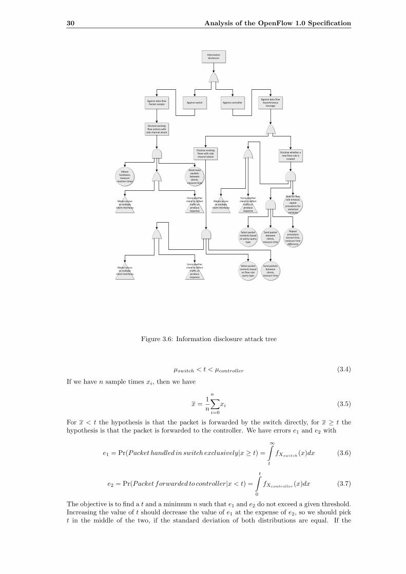
30 Analysis of the OpenFlow 1.0 Specification
Information disclosure
Against switch Against controller
Disclose existing flows with side channel attack
Disclose whether a new flow rule is
created
Send packets between clients,
measure time
Disclose existing flow actions with
side channel attack
Obtain hardware, measure
reaction times
Send many packets
between clients,
measure time
Send packet between clients,
measure time
Repeat procedure
second time, measure time difference
Obtain access to multiple
client interfaces
Obtain access to multiple
client interfaces
Force another client to reflect
traffic or produce response
Force another client to reflect
traffic or produce response
Obtain access to multiple
client interfaces
Force another client to reflect
traffic or produce response
Wait for flow rule timeout,
repeat procedure for
statistical certainty
Select packet contents based on policy query
type
Select packet contents based
on flow rule query type
Against data flow Packet sample
Against data flow Asynchronous
message
Figure 3.6: Information disclosure attack tree
µswitch < t < µcontroller (3.4)
If we have n sample times xi, then we have
x =
n1
n
∑i=0
xi (3.5)
For x < t the hypothesis is that the packet is forwarded by the switch directly, for x ≥ t thehypothesis is that the packet is forwarded to the controller. We have errors e1 and e2 with
e1 = Pr(Packet handled in switch exclusively|x ≥ t) =
∞
t
fXswitch(x)dx (3.6)
e2 = Pr(Packet forwarded to controller|x < t) =
tˆ
0
fXcontroller(x)dx (3.7)
The objective is to find a t and a minimum n such that e1 and e2 do not exceed a given threshold.Increasing the value of t should decrease the value of e1 at the expense of e2, so we should pickt in the middle of the two, if the standard deviation of both distributions are equal. If the
3.5 Attack Trees 31
standard deviation of the distributions is not equal, then we should choose a threshold closerto the mean of the distribution with the smaller standard deviation. The following formulareturns a threshold t, which is the linear combination of the means of both distributions, witheach mean’s contribution to the threshold value being proportional to the other distribution’sstandard deviation σ:
t = µswitch + (µcontroller − µswitch) · σswitch
σswitch + σcontroller(3.8)
3.5.3.2 Determining what Action a Flow Rule Will Take
The objective of this attack would be to find out which actions a particular flow rule is configuredwith. The essential attack methodology is the same as above, but instead of attempting todetermine whether a packet is sent to the controller, we attempt to determine if the switch isperforming some extra processing. The premise is that the switch can either perform operationsin hardware (which is the fastest), on its own processor (less quick), or it may send the packetto the controller - which is much slower. This is an attack against the packet sample data flow(3.4.3.1).
Assuming that we can obtain a sample device - which requires that we determine the device inuse - and probe it extensively, we may be able to determine the timing characteristics of certainoperations: Obviously, if the operation is to forward to the controller (this is one of the virtualports available), this will be noticeable. But other virtual port forwarding operations may beimplemented in software instead, and it is also possible that the packet modification operationsare implemented in software too. Some of these operations (such as packet modification) are alsodirectly observable. This would seem to make such a timing attack useless - however, we couldconsider the same in reverse, namely use the timing characteristics of the switch to determine thehardware in use. In order to obtain certainty, a large number of packets will have to be sent, asthe time differences are on a much smaller scale of magnitude, compared to the round trip timeof the connection. Operations which use the software of the switch may offer a possibility for adenial of service attack, especially if the operation involves sending a packet to the controller.
3.5.3.3 Determining whether a Flow Rule will be Created
The objective of this attack on the Asynchronous Message data flow is to find out whether a newflow rule is created in response to a particular packet. This is of particular interest if we wishto perform a denial of service attack, as here the switch will not be able to operate at line rate.The attacker would send two packets, with a short delay in between, allowing the controller toinstall a flow rule, if needed. If a new flow rule is created, the time duration between the repliesto the packets will be much smaller for the second packet than for the first. This attack is usefuleven without any kind of source address spoofing, as we are less interested in the current networksetup than how the controller responds to new flows, and we probably intend to follow this upwith another type of attack.
3.5.3.4 Determining whether a Flow Rule Will Be Created with Wildcards (aggre-gation) or as an Exact Match
The objective of this attack (once again against the data flow Asynchronous Message) is moresubtle: Rather than simply determining whether a flow rule will be created or not, insteaddetermine the granularity of the created flow rule. It may be either matched to a single flow,resulting in a separate flow rule for every flow through the switch, or a subset thereof, which isa reactive strategy . Alternatively, flow rules may be created to cover several rules at a time, aproactive strategy . Realistically, some combination of the above may be used; it is also possiblethat an adaptive strategy is in use. Such a strategy would change between reactive and proactive“extremes” depending on the circumstances. In particular, it may decide that a number of similarflow rules may be aggregated into a single flow rule.
32 Analysis of the OpenFlow 1.0 Specification
Identify which flow rules are created with or without
wildcards
Determine from timing analysis
Obtain access to multiple
client interfaces
Force another client to reflect
traffic or produce response
Compromise controller
Social engineering or educated guess
Send packet between clients,
measure time
Repeat procedure
second time, measure time difference
For each header column, select
two neighboring
values
Wait for flow rule timeout,
repeat procedure for
statistical certainty
Ensure that adjacent client addresses are
available, if address is to be
probed
Secure multiple source addresses, if
needed.
Send falsified ARP or LLDP or routing packets
to redirect traffic
Obtain access to multiple
client interfaces
Use forged source addresses
Figure 3.7: Subtree for determining whether aggregation is in use
3.5.4 Denial of Service
Attacks here will be performed by generating a very large number of packets, possibly instanti-ating new flows. Considering the switch, possible targets for attack are the Flow Table, which wemay attempt to fill, and the control plane (OpenFlow Module, Secure Channel or OpenFlow In-terface). Based on a reference implementation[41], it is safe to assume that part of the switchingoperation will be carried out in hardware, and part in software. Depending on how the switch isimplemented, this may present a possibility to overload the CPU of the switch with operationsthat are implemented in software, including the sending of packets to the controller. It is this lastoperation that also provides avenues of attack against the controller as well. Overloading such acontroller may be far more critical, if it operates multiple switches. Unless the controller has asecurity fault that we may exploit, we are forced to attempt to overload its network connectionand/or processing capabilities. A critical shortcoming of the OpenFlow 1.0 specification is itsreaction to the overflow of an interface input buffer, which we may attempt to put into effect bycreating a very large number of flows simultaneously. The reaction of the switch is, according tothe specification, to send entire packets rather than headers24, which will result in us consumingthe same amount of bandwidth on the management connection as on the data plane. Even ifwe are unable to overflow an input buffer, the sum of several attacks on various interfaces ofthe switch may be enough to result in an overload of the switch’s management interface. Either
24Presumably to prevent packets from being lost.
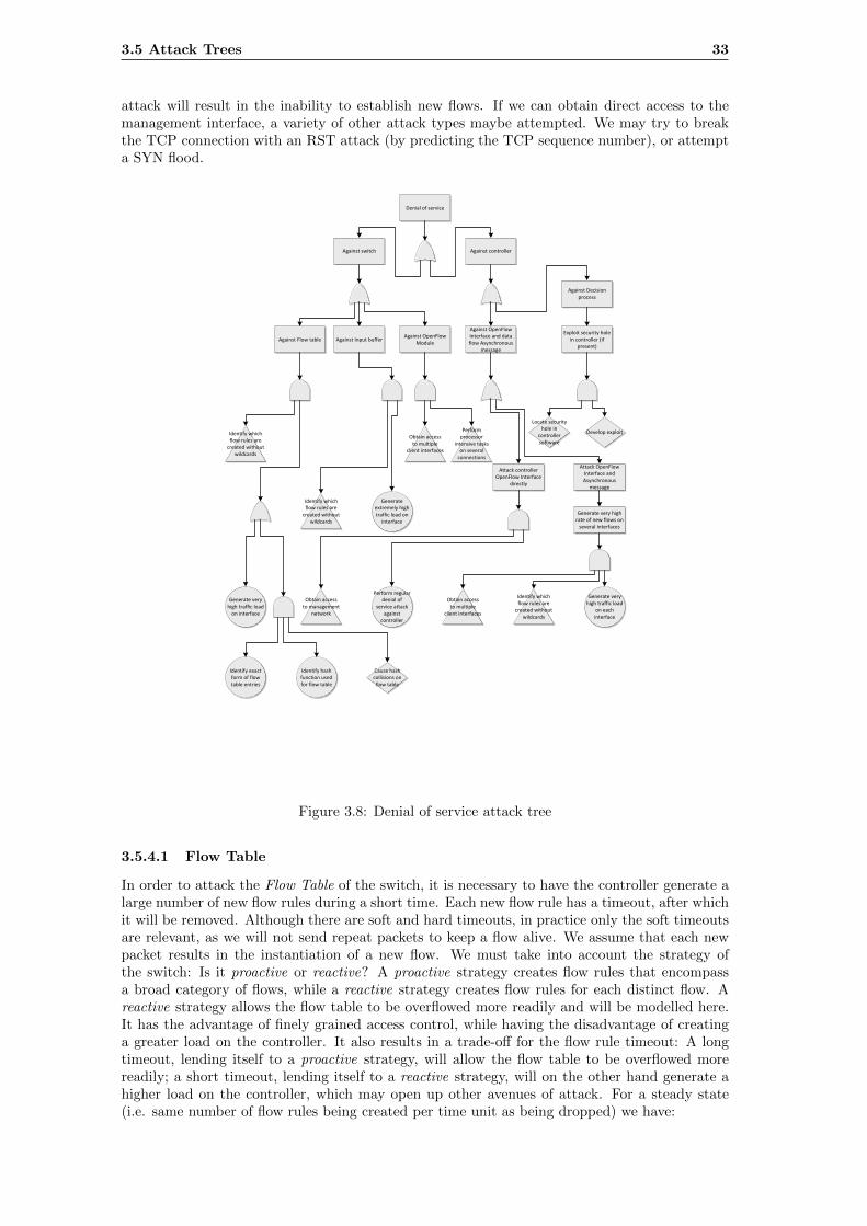
3.5 Attack Trees 33
attack will result in the inability to establish new flows. If we can obtain direct access to themanagement interface, a variety of other attack types maybe attempted. We may try to breakthe TCP connection with an RST attack (by predicting the TCP sequence number), or attempta SYN flood.
Denial of service
Against switch Against controller
Against Flow table
Against OpenFlow Interface and data flow Asynchronous
message
Against OpenFlow Module
Generate very high traffic load
on interface
Exploit security hole in controller (if
present)Against Input buffer
Attack controller OpenFlow Interface
directly
Perform regular denial of
service attack against
controller
Attack OpenFlow Interface and Asynchronous
message
Generate very high rate of new flows on
several interfaces
Generate very high traffic load
on each interface
Generate extremely high traffic load on
interface
Obtain access to multiple
client interfaces
Obtain access to multiple
client interfaces
Obtain access to management
network
Locate security hole in
controller software
Develop exploitPerform processor
intensive tasks on several
connections
Identify which flow rules are
created without wildcards
Identify which flow rules are
created without wildcards
Identify which flow rules are
created without wildcards
Against Decision process
Identify exact form of flow table entries
Identify hash function used for flow table
Cause hash collisions on
flow table
Figure 3.8: Denial of service attack tree
3.5.4.1 Flow Table
In order to attack the Flow Table of the switch, it is necessary to have the controller generate alarge number of new flow rules during a short time. Each new flow rule has a timeout, after whichit will be removed. Although there are soft and hard timeouts, in practice only the soft timeoutsare relevant, as we will not send repeat packets to keep a flow alive. We assume that each newpacket results in the instantiation of a new flow. We must take into account the strategy ofthe switch: Is it proactive or reactive? A proactive strategy creates flow rules that encompassa broad category of flows, while a reactive strategy creates flow rules for each distinct flow. Areactive strategy allows the flow table to be overflowed more readily and will be modelled here.It has the advantage of finely grained access control, while having the disadvantage of creatinga greater load on the controller. It also results in a trade-off for the flow rule timeout: A longtimeout, lending itself to a proactive strategy, will allow the flow table to be overflowed morereadily; a short timeout, lending itself to a reactive strategy, will on the other hand generate ahigher load on the controller, which may open up other avenues of attack. For a steady state(i.e. same number of flow rules being created per time unit as being dropped) we have:
34 Analysis of the OpenFlow 1.0 Specification
Rflow rule =
{Rclnt
spkt
Rclnt
spkt<
Rmgmt
shdrRmgmt
shdr
Rclnt
spkt≥ Rmgmt
shdr
(3.9)
Rflow rule >nflow table
tflow table(3.10)
where
Rflow rule is the maximum number of flow rules that can be generated per second
Rclnt is the throughput available between the client system performing the attack and theswitch
Rmgmt is the throughput available between the switch and the controller, including overheadfor encryption
spkt is the size of packet required to effect the installation of a new flow rule
shdr is the size of the encapsulated header sent to the controller
nflow table is the maximum number of entries in the flow table and
tflow table is the average dwelling time of a flow rule in the flow table (i.e. the flow rule timeout).
If this criterion is met, then an overflow of the flow table will occur. Note that the second case,i.e. Rclnt
spkt≥ Rmgmt
shdrwill eventually also result in the input buffer overflowing, leading us to an
attack on the input buffer instead.Depending on the implementation of the flow table in the hardware and/or software of the switch,other avenues of attack may exist. In general, a flow table will be implemented with the aid ofa hash table25. A hash table in general provides lookups with amortised O(1) performance,compared to a self-balancing binary search tree which offers O(log n) performance, but this isguaranteed even for worst case input data. Any hash table is vulnerable to hash collisions;these are generally resolved using a linked list. Linked lists have an O(n) lookup and insertiontime, but as the hash function is assumed to be uniformly distributed and the hash table sizeis proportional to the maximum flow table size, this results in an essentially constant numberof lookups for each query in the average case. However, if it is possible to cause hash collisionsto occur predictably, the hash table will degenerate into a linked list, demonstrating worst caseperformance, i.e. O(n) lookup time. For a large value of n, this may degrade performanceconsiderably, especially considering the requirement that the lookups occur at line rate. [8] givesfurther information about this sort of attack, which may also be relevant to the controller, incase it stores system state in a hash table.
3.5.4.2 Input Buffer
Rather than attempting to overflow the flow table, we may attempt to overflow the Input Buffer(of a network interface) instead. Due to the semantics of the OpenFlow protocol, if the switch isfully compliant then whole packets will be sent to the controller rather than just headers, mostlikely to avoid data loss if no buffer is available. This will make a denial of service attack againstthe controller much more straightforward. Assuming that the switch does not drop any packetsby itself, but always forwards them to the controller, we have:
Rclnt
spkt≥ Rmgmt
shdr(3.11)
as the criterion for an overflow of the input buffer and
sibufspkt
< nflow table (3.12)
with
25This is the case in Open vSwitch, which is the basis of Mininet. This can be verified by examining the sourcecode.
3.5 Attack Trees 35
sibuf as the input buffer size
being the differentiating criterion between an overflow of the flow table or of the input buffer.In reality, the switch is likely to drop packets, either at random or due to some criteria (suchas QoS). Depending on which interface the attack is being performed on, this may or may notprevent the objective of the attack from being attained. If the client system is attached directlyto the switch, only its own traffic will be affected by this behaviour. If the interface is connectedto a number of other systems, then all of these will be unable to communicate via the switch. Inthe most extreme (but realistic) case, where the affected interface is connected to the rest of theInternet, Internet connectivity may be lost. In such a case, a protective mechanism which dropspackets according to some predictable criteria, or at random, will help to accomplish the goal ofthe attack.
3.5.4.3 OpenFlow Module
It also possible that the software component (i.e. OpenFlow Module) may be attacked. As notedin 3.5.3.2, operations which are performed in software take longer. Unlike the data path, whichis essentially “guaranteed” to run at line rate, the software component of the switch, insofar as itis used for forwarding operations, may be a bottleneck. It is necessary to know about the switchinternals in order to perform such an attack, and considerably more traffic may be required thanother denial of service attack possibilities. However, the attack does not depend on having flowrules installed, and therefore does not depend on a particular policy being followed.
3.5.4.4 Management Interface and/or Controller
Instead of considering the switch as a target, we may also consider the switch-controller interface,i.e. the Secure Channel or OpenFlow Interface elements. In the case of a single switch andcontroller setup, as we have modelled here, there is little difference in effect. But if, as seems likelyin a production system, the controller is responsible for multiple switches, attacking the controllerwould have effects on all of them. This would make it a high value target for any attacker wishingto cause maximum disruption. Any such attack would use the same methodology as an attackon the flow table or input buffer. An attack that manages to overflow the input buffer of theswitch would be particularly effective (as noted in the previous section), as it would amplify theeffective traffic level sent to the controller. The possibility of attacking the controller throughmultiple interfaces, or even multiple switches, must also be taken into consideration. For multipleinterfaces 1 . . . k, we have
k∑i=1
Rclnt,i
spkt,i≥ Rmgmt
shdr(3.13)
which allows us to overwhelm the switch-controller connection more easily, especially consideringthe extra overhead (encapsulation, encryption) that this connection requires. In the case ofmultiple switches, the effect of denial of service attacks against all of them simultaneously wouldbe cumulative, leading to a very high load on the controller. In this case, even if the managementinterface could handle the traffic, the controller software itself may not be able to.
3.5.5 Attack Prerequisites
Some attacks have certain prerequisites in order to be executed successfully. These are discussedbelow.
3.5.5.1 Access to Multiple Client Interfaces
It may be necessary to have access to two or more clients, or at least be able to communicatewith two clients across the switch. This is required for timing analysis; it is also beneficial to havemultiple ports available for a denial of service attack. There are fundamentally two approaches:Firstly, we could attempt to gain control of a client system connected to the switch. Alternatively,we could try to get access to the network itself.
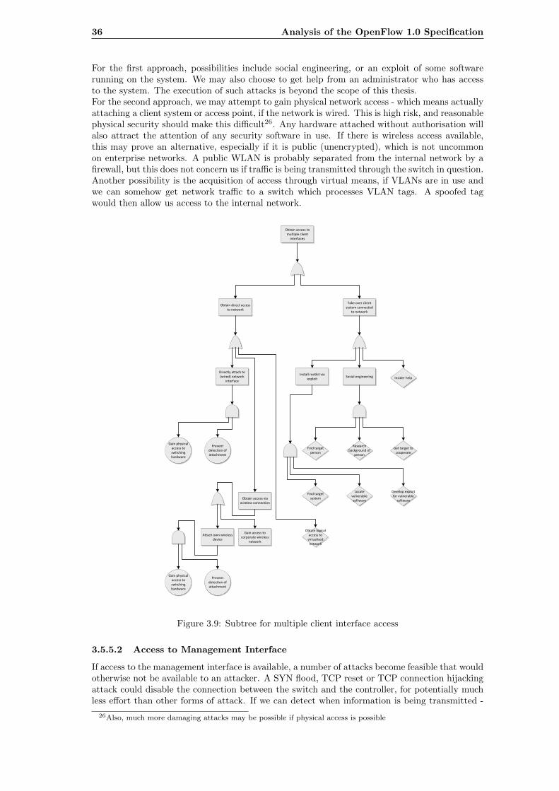
36 Analysis of the OpenFlow 1.0 Specification
For the first approach, possibilities include social engineering, or an exploit of some softwarerunning on the system. We may also choose to get help from an administrator who has accessto the system. The execution of such attacks is beyond the scope of this thesis.For the second approach, we may attempt to gain physical network access - which means actuallyattaching a client system or access point, if the network is wired. This is high risk, and reasonablephysical security should make this difficult26. Any hardware attached without authorisation willalso attract the attention of any security software in use. If there is wireless access available,this may prove an alternative, especially if it is public (unencrypted), which is not uncommonon enterprise networks. A public WLAN is probably separated from the internal network by afirewall, but this does not concern us if traffic is being transmitted through the switch in question.Another possibility is the acquisition of access through virtual means, if VLANs are in use andwe can somehow get network traffic to a switch which processes VLAN tags. A spoofed tagwould then allow us access to the internal network.
Obtain access to multiple client
interfaces
Obtain direct access to network
Take over client system connected
to network
Social engineeringInstall rootkit via
exploit
Directly attach to (wired) network
interface
Gain physical access to switching hardware
Prevent detection of attachment
Obtain access via wireless connection
Gain access to corporate wireless
network
Attach own wireless device
Gain physical access to switching hardware
Prevent detection of attachment
Find target person
Research background of
person
Get target to cooperate
Find target system
Locate vulnerable software
Develop exploit for vulnerable
software
Insider help
Obtain logical access to
virtualised network
Figure 3.9: Subtree for multiple client interface access
3.5.5.2 Access to Management Interface
If access to the management interface is available, a number of attacks become feasible that wouldotherwise not be available to an attacker. A SYN flood, TCP reset or TCP connection hijackingattack could disable the connection between the switch and the controller, for potentially muchless effort than other forms of attack. If we can detect when information is being transmitted -
26Also, much more damaging attacks may be possible if physical access is possible
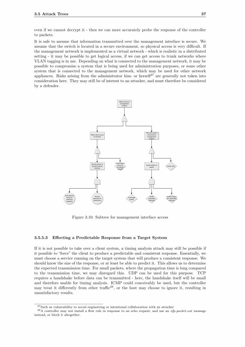
3.5 Attack Trees 37
even if we cannot decrypt it - then we can more accurately probe the response of the controllerto packets.
It is safe to assume that information transmitted over the management interface is secure. Weassume that the switch is located in a secure environment, so physical access is very difficult. Ifthe management network is implemented as a virtual network - which is realistic in a distributedsetting - it may be possible to get logical access, if we can get access to trunk networks whereVLAN tagging is in use. Depending on what is connected to the management network, it may bepossible to compromise a system that is being used for administration purposes, or some othersystem that is connected to the management network, which may be used for other networkappliances. Risks arising from the administrator him- or herself27 are generally not taken intoconsideration here. They may still be of interest to an attacker, and must therefore be consideredby a defender.
Obtain access to management
network
Obtain direct access to network
Take over system connected to management
network
Install rootkit via exploit
Directly attach to (wired) network
interface
Gain physical access to switching hardware
Prevent detection of attachment
Insider help
Find target system
Locate vulnerable software
Develop exploit for vulnerable
software
Obtain logical access to
virtualised network
Figure 3.10: Subtree for management interface access
3.5.5.3 Effecting a Predictable Response from a Target System
If it is not possible to take over a client system, a timing analysis attack may still be possible ifit possible to “force” the client to produce a predictable and consistent response. Essentially, wemust choose a service running on the target system that will produce a consistent response. Weshould know the size of the response, or at least be able to predict it. This allows us to determinethe expected transmission time. For small packets, where the propagation time is long comparedto the transmission time, we may disregard this. UDP can be used for this purpose. TCPrequires a handshake before data can be transmitted - here, the handshake itself will be smalland therefore usable for timing analysis. ICMP could conceivably be used, but the controllermay treat it differently from other traffic28, or the host may choose to ignore it, resulting inunsatisfactory results.
27Such as vulnerability to social engineering or intentional collaboration with an attacker28A controller may not install a flow rule in response to an echo request, and use an ofp packet out message
instead, or block it altogether.
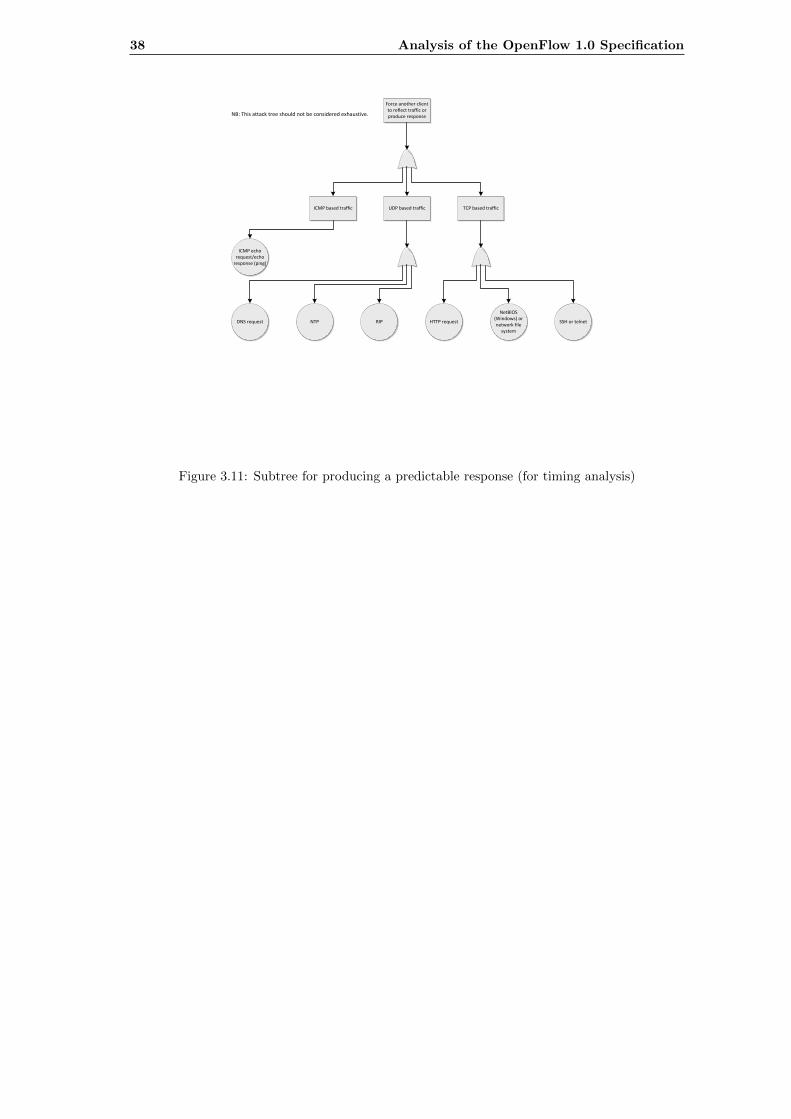
38 Analysis of the OpenFlow 1.0 Specification
Force another client to reflect traffic or produce response
UDP based trafficICMP based traffic TCP based traffic
ICMP echo request/echo
response (ping)
DNS request NTP RIP HTTP request
NetBIOS (Windows) or network file
system
SSH or telnet
NB: This attack tree should not be considered exhaustive.
Figure 3.11: Subtree for producing a predictable response (for timing analysis)
Chapter 4
Changes Introduced in NewerVersions of OpenFlow
4.1 Introduction
In this chapter, the changes made to OpenFlow since the first production specification (1.0, asanalysed in Chapter 3) was released are examined for potential security implications. In Section4.2, a short history of OpenFlow specifications is presented. The subsequent sections evaluatethe security implications of the changes introduced in each of the production specifications.
4.2 History
Presently, OpenFlow is managed by the Open Networking Foundation[46], a consortium of ITcompanies and network hardware manufacturers. After a period of development, the first releaseof the OpenFlow specification was made at the end of 2009; to-date this remains the most widelyimplemented one, especially in hardware. There is also a set of specifications for the OpenFlowConfiguration and Management Protocol, but this is only used to configure switches and has littlerelevance, assuming that switches are managed from a separate network. Table 4.1 shows thedifferent versions of the OpenFlow Switch Specification.
Specification Published Wire Protocol For production use
OpenFlow Switch Specification 1.3.1 06.09.2012 0x04 "
OpenFlow Switch Specification 1.3.0 13.04.2012 0x04 "
OpenFlow Switch Specification 1.2 05.12.2011 0x03 "
OpenFlow Switch Specification 1.1.0 28.02.2011 0x02 "
OpenFlow Switch Specification 1.0.0 31.12.2009 0x01 "
OpenFlow Switch Specification 0.9.0 20.07.2009 0x98 #
OpenFlow Switch Specification 0.8.9 02.12.2008 0x97 #
OpenFlow Switch Specification 0.8.2 17.10.2008 0x85 #
OpenFlow Switch Specification 0.8.1 20.05.2008 0x83 #
OpenFlow Switch Specification 0.8.0 05.05.2008 0x83 #
OpenFlow Switch Specification 0.2.1 28.03.2008 (1) #
OpenFlow Switch Specification 0.2.0 28.03.2008 (1) #
Table 4.1: Versions of the OpenFlow Switch Specification
39
40 Changes Introduced in Newer Versions of OpenFlow
Each specification has a wire protocol, which indicates the version of the protocol syntax; specifi-cations sharing a wire protocol version have the same syntax, although the semantics may havechanged. The OpenFlow protocol is backwards compatible in the sense that any controller andany switch that follow the specification are capable of interacting - they will utilise the latestprotocol version supported by both. At any rate, a list of supported features is exchanged aspart of the protocol handshake (OFPT FEATURES REQUEST ), allowing implementations tonegotiate the use of features beyond those required by the specification.
4.3 OpenFlow Switch Specification 1.1.0
4.3.1 Outline of Changes
� Support for multiple flow tables
� Support for group table
� Support for multiple layers of VLAN tags
� Support for virtual ports (collections of physical ports)
� Removal of support for emergency flow cache
� Support TTL decrementation
� Support for SCTP, ECN rewriting
� Message handling semantics defined (out of order handling)
In the following subsections, we highlight the most important changes in v1.1.0, and whetherthey are security-relevant or not.
4.3.2 Multiple Flow Tables
The 1.0 specification does not support multiple tables, at least not from the perspective ofthe controller - the switch may use multiple tables internally. The addition of support formultiple flow tables was intended to allow the OpenFlow controller to better utilise the hardwarecapabilities of the controller, as well as allowing different layers of flow rules. These could beused for different purposes, for instance access control or traffic prioritisation. This would tendto reduce the number and complexity of flow rules. The 1.1 specification requires that metadataand state information be stored for each packet as it is processed by the various flow tables,which have an index starting at zero, allowing subsequent flow tables to extend or modify theaction sets based on previous tables’ flow rules. Also, flow rules can specify that packets beforwarded to another flow table. It is only permitted to forward to tables with a higher index,preventing the existence of loops. After each table, an action can be added to the action set.When there are no more tables to forward to, or a flow rule does not specify which is the nexttable to be used, the accumulated action set is executed. It is also possible to execute actionsimmediately, without affecting the action set. These changes increase complexity (and thereforeprocessing time, especially under load). It is therefore probably advisable to make use of a formalvalidation if complicated, multi-table setups are to be used. In particular, it should be shownthat accumulated actions from multiple tables are not contradictory.
4.3.3 Group Table
The 1.1 specification adds support for a group table. The group table contains groups, each havinga list of actions, forming an action bucket. Groups and buckets both have counters attached.There are four types of groups: All, select, indirect and fast fail-over. The all type group executesall of the action buckets. It is intended to implement multi- and broadcast forwarding. The selecttype group executes one action bucket, the selection of which is implementation dependent. It isintended to allow forwarding along multiple paths for redundancy purposes. The indirect type is
4.3 OpenFlow Switch Specification 1.1.0 41
the same as an all type with just one bucket. It is intended to be used to simplify setups wheremultiple flow rules perform the same (complicated) action. The fast failover type forwards to thefirst action bucket marked as live, the liveness attribute being associated with a port or group ofports. As the name suggests, it can be used to perform alternate routing without first contactingthe switch. These mechanisms can be used to increase the resilience of the OpenFlow systemwith less complexity.
4.3.4 Emergency Flow Cache
The 1.0 specification (section 4.3) requires that the flow table have a field for an emergencybit. In case the switch loses contact with the controller1, all flow table entries are deleted apartfrom those marked with this bit. These rules must be manually removed by the controller if nolonger desired. The 1.1.0 specification removes this feature and instead adds two failure modes:Secure and standalone. In the secure mode, the switch behaves as if all of the flows were markedwith the emergency bit. The switch keeps its set of flow rules, the only difference being thatpackets are no longer forwarded to the controller. Flow rules maintain their timeouts, and somay eventually expire. The standalone mode makes the switch behave as an ordinary Ethernetswitch, requiring that this functionality be available in the switch software or firmware.
These changes are security relevant: Any denial of service attack or transient failure which resultsin a loss of connectivity to the controller will result in the switch behaving differently. Thestandalone mode ensures continued connectivity, but may result in security properties becomingcompromised, allowing unauthorised access to network hosts. On the other hand, the securemode may result in a gradual loss of availability. The new behaviour does have the advantage ofgreater simplicity.
4.3.5 Message Handling Semantics
The OpenFlow 1.1 specification introduces the requirement that the control channel be reliable,in that delivery of control messages is guaranteed. This does not represent any change in practice,as the control channel is generally implemented over TCP[50], which itself guarantees delivery,although it does clarify that in the case of switch failure, no assumption can be made about switchbehaviour. All messages from the controller to the switch must be processed, and an error messagemust be sent to the controller if processing is not possible, though in the case of an ofp packet outmessage the packet itself may be dropped silently under certain circumstances. The switch isrequired to report to the controller all internal state changes, including flow rule expiry. However,ofp packet in messages can be dropped in the case of congestion. The controller is completelyunrestrained by the OpenFlow protocol; it is not required to respond to any messages sent bythe switch. These changes may affect the behaviour the the switch and controller in the eventof a denial of service attack.
The specification also notes that the switch may freely change the ordering of packets; the con-troller must not rely on the packets being processed in the input order. The barrier message canbe used to ensure that messages are processed in a particular order, which is required especiallyif dependencies exist between messages. This possibility, as well as the potential reordering ca-pability, introduce the aspect of timing into security considerations. As with all asynchronoussystems, race conditions may be an issue, and this should be taken into consideration if controllerpolicy results in interdependencies being introduced. As with 4.3.2, the use of formal validationis desirable.
4.3.6 VLAN Tags
The OpenFlow 1.1.0 specification allows frames containing multiple 802.1Q tags to be processedand the VLAN ID and QoS tag fields they contain to be matched against. Some networksetups require multiple embedded layers of virtual networks and other network setups may besimplified by this functionality - it is possible to encapsulate multiple virtual networks insideanother virtual network. Multiple tags may be managed as a stack, with push and pop actionssupported. However, this makes a type of attack called VLAN hopping possible, where packets
1The switch would establish this due to lack of reply to an OFPT ECHO REQUEST message.
42 Changes Introduced in Newer Versions of OpenFlow
with multiple VLAN tags can be forwarded to other virtual network segments, if care is nottaken when configuring the network[13].
4.3.7 Summary
The 1.1 specification represents the first revision after the original production specification. Anumber of the changes (e.g. 4.3.5) represent clarifications of behaviour which were previously notdefined in the specification. The aforementioned modification merely made clear the generallyasynchronous nature of the system, and the necessity for the explicit enforcement of ordering withbarrier messages, if it is desired. Other changes (e.g. 4.3.4) are a result of the experience thatcertain features were not implemented in practice - the new behaviour is much simpler, also froma security perspective. The addition of support for TTL decrementation is possibly a correctionof an oversight made during the original specification which prevented the use of OpenFlow forlayer 3 switching. An issue concerning both this and future specifications is greater complexity:Multiple flow tables greatly increase the complexity of the processing pipeline, and introduce thepossibility of inconsistency between different tables. The more complicated state and processingincreases the potential for vulnerabilities. To a lesser extent the same principle applies to supportfor multiple VLAN tags or virtual ports. It is important that the added complexity is weighedagainst actual usage of the new functionality, so that additional complexity is not introducedmerely to cover corner cases (which should be dealt with by extensions, or be turned off bydefault).
4.4 OpenFlow Switch Specification 1.2
4.4.1 Outline of Changes
� Extensible header field matching and rewriting
� Changes to OFPT FLOW IN syntax
� Extensible error messages
� Support for IPv6 (via new extensible field support)
� Changes to OFPT FLOW MOD semantics
� Facilitation of controller fail-over and load balancing
� Packet buffering can be turned off (OFPCML NO BUFFER)
� Max-rate queue property added
In the following subsections, we highlight the most important changes in v1.2, and whether theyare security-relevant or not.
4.4.2 Field Matching and Rewriting
The OpenFlow 1.2 specification completely overhauls field matching and rewriting functionality.Instead of sending fields specified as part of a static header, the specification instead allows themto be specified in a data structure called OXM (OpenFlow Extensible Match). This structurestores the fields in a type-length-value format, allowing support for new fields to be added easilyas well as allowing for arbitrary masks. This mechanism is also used to specify field rewriteactions. The type field has a class subfield, allowing for extensions to add new sets of fields; thiscould in particular be used to add support for matching application layer fields to OpenFlow(i.e. support for deep packet inspection), which would allow considerably more flexibility whereOpenFlow is being used to enforce access control or ease lawful interception of the packet streams.
4.4 OpenFlow Switch Specification 1.2 43
4.4.3 Packet Buffering
The OpenFlow 1.2 specifications allows the controller to deactivate packet buffering on the switchusing OFPCML NO BUFFER. The switch is then required to send full packets to the controller,imitating the existing behaviour in the event of the buffer being full. The deactivation of buffer-ing on the switch may considerably increase the load on the controller-to-switch connection,although it trivially precludes the possibility of the input buffer overflowing. The utilisation ofthis functionality might allow an attacker to overload the secure channel or the controller withlarge packets.
4.4.4 Multiple Controllers
The OpenFlow 1.2 specifications establishes support for multiple controllers for a single switch,allowing load balancing and fail over. Virtualisation does not require these mechanisms andcan be supported with the 1.0 specification. Controllers are now assigned one of three roles:Master, slave or equal, the last being the default option. A switch can connect to any numberof equal or slave controllers, but only one master controller is supported. The switch maintainsconnections to all controllers, accepting controller-to-switch messages from each as permitted bythe controller’s role, and sending asynchronous messages to all relevant controllers. The switchdoes not perform arbitration, therefore hand-over to other controllers needs to be implementedon the controller. Moreover, the controller may change its role at any time. A controller in themaster or equal role may send any message to the switch and will receive any relevant responsegenerated by messages it sent. A controller which becomes a master will relegate the previousmaster to slave role, which entails read-only access to the switch; any operation which changesthe switch state is prohibited.
Support for multiple controllers increases the robustness of the OpenFlow system considerably:The lack of a single point of failure makes denial of service attacks less effective, and the use ofload balancing increases scalability, also allowing more effective handling of large loads. Questionsarising from a security perspective include the possibility of race conditions, if controllers do notsynchronise their actions properly, as well as questions on the impact of timing analysis attacks;it may be possible to determine which controller is controlling a given switch if the networktopology is asymmetrical (a form of information disclosure attack). The security impact couldonly reasonably be assessed when the setup and topology of the controllers is defined.
4.4.5 IPv6 Support
The OpenFlow 1.2 specification introduces support for matching and rewriting IPv6 as wellICMPv6 header fields. This capability is added via the flexible matching described in 4.4.2.Support for IPv6 is a logical and necessary extension to the OpenFlow, if it is to be used after thetransition to IPv6. IPv6 introduces new mechanisms for address resolution (c.f. neighbourhooddiscovery[42]) which should be examined for spoofing possibilities. These may lead to tamperingattacks, as discussed in 3.5.2.2.
4.4.6 Summary
A major theme in this revision is the increase in flexibility: We have 4.4.2 and 4.4.4 as theprimary changes. The flexible matching support also enables support for IPv6 (4.4.5). Thematching may have security relevance, especially if payload matching is used in flow rules. Thesupport for multiple controllers is a major novelty which offers the possibility of redundancyand some limited forms of load balancing, although the OpenFlow Switch Specification 1.3.0increases this capability considerably. Although this may be a generally positive contribution tothe security of OpenFlow, the use of multiple controllers, especially the critical transition phasewhen control is transferred from one to another, must be examined in order to discover anypossible race conditions.
44 Changes Introduced in Newer Versions of OpenFlow
4.5 OpenFlow Switch Specification 1.3.0
4.5.1 Outline of Changes
� Redesign of capabilities negotiation during handshake
� More flexible handling of unmatched packets (special flow table entry)
� IPv6 extension header handling (detection of presence in packet)
� Flow rules can now specify rate limiting
� Controller can now specify filters for asynchronous messages
� Allow auxiliary connections to controller in order to enable parallelism
� Statistics include duration field, counters can now be disabled
In the following subsections, we highlight the most important changes in v1.3.0, and whetherthey are security-relevant or not.
4.5.2 Unmatched Packets
The OpenFlow 1.3.0 specification changes the reaction of the switch in case of a packet notmatching any flow rule (in a given table, in case multiple tables are in use): Instead of havingflags to specify behaviour in this case, a new fallback default flow rule is used instead. This rule’sactions are then executed. This change allows more flexibility when dealing with unmatchedpackets, since it is for example possible to have these processed by a switch’s conventional pipeline,if the switch is a hybrid rather than a pure OpenFlow switch. In the absence of any default flowrule, the packet is simply dropped. This may be of use in case the switch is under severe load,although this behaviour may also allow information to be derived about the contents of the flowtable and/or switch state.
4.5.3 IPv6 Extension Header Handling
The OpenFlow 1.3.0 specification adds (via OXM, see 4.4.2) support for matching the presenceof the various IPv6 header extensions. This change should allow more flexibility when enforcingpolicy in IPv6 networks. For instance, it would be possible to reject packets containing a routingheader.
4.5.4 Meters
The OpenFlow 1.3.0 specification adds a new data structure called a meter table. Each entryin the table is a meter, each meter having one or more meter bands. The meters are used byapplying an action to an incoming packet. Any number of flow rules can use one meter, and allpackets sent to a meter will result in the meter being updated accordingly. Once a meter bandis exceeded, the band is triggered and the action is performed on all packets sent to the meter,until the next band is triggered. The action would most likely be to drop the packet, althoughit can also be used to implement DiffServ and similar QoS strategies. This would also applyto the fallback rules introduced in 4.3.4. The meters also have counters; these are not used forenforcing the bands but rather for informational purposes. A major application of the feature isto limit the number of messages sent to the controller, which would be invaluable in preventingdenial of service attacks. This feature could also allow countermeasures against denial of serviceattacks targeting client systems in the OpenFlow network.
4.5.5 Event Filtering
The OpenFlow 1.3.0 specification allows all controllers to add a filter to the switch-controllerconnection using an asynchronous configuration message. This prevents the switch from sendingcertain asynchronous messages to the affected controller - messages which can be filtered arepacket in, port status and flow removed. The controller can specify which of these message typesit does not want to receive; it is also possible to install separate filters for different controller roles
4.6 OpenFlow Switch Specification 1.3.1 45
(master and equal versus slave). This functionality can improve scalability, allowing separatecontrollers to handle different event types, as well as decreasing the load on the individualcontroller caused by asynchronous messages.
4.5.6 Auxiliary Connections
The OpenFlow 1.3.0 specification introduces the possibility of having multiple, parallel connec-tions between the switch and the controller. One of the connections will be designated as themain connection (the one with a connection ID of zero), all of the others are considered auxiliaryconnections and may be used only when the main connection is active (i.e. they are not “backup”connections). Auxiliary connections must share the same source IP as the main connection, butthe port and transport mode may be different. Certain transport modes do not guarantee reliabledelivery of messages (e.g. UDP), and the OpenFlow protocol does not itself provide any methodfor ensuring delivery. Alternative transport modes may also deviate from in-order delivery andthere is no defined ordering between two channels; in order to ensure that two messages aredelivered in a given order, a reliable transport protocol must be used (e.g. plain TCP or TLS),the messages must be sent over the same channel and a barrier message must be placed betweenthem. The intent of this feature is to improve performance and exploit parallel designs in switchesby allowing packet-in and packet-out messages to be sent concurrently2. Although the sendingof concurrent messages introduces the possibility of race conditions, 4.3.5 already introduced thispossibility, which must be taken into consideration by the controller. This change may allow thecontroller to cope with denial of service attacks more effectively by exploiting parallelism.
4.5.7 Summary
The OpenFlow 1.3.0 specification also increases flexibility and controllability, with the changesto handling of unmatched packets and the possibility of disabling counters (see 3.5.4.3). Supportfor matching IPv6 headers can be considered an extension of the support added in the previousspecification. The new specification contains several new features which jointly address one of themajor shortcomings of the OpenFlow specification, namely the issue of scalability. The supportfor flow meters has a potential to greatly reduce the impact of denial of service attacks, as wellas merely incidental congestion. Likewise, the support for auxiliary connections allows greaterperformance as well as more parallelism, both on the switch and on the controller. Finally,support for controllers filtering events complements the multiple controller support added in the1.2.0 specification, making it more useful for load balancing purposes. Unfortunately, the degreeof control offered for the filter is quite limited.
4.6 OpenFlow Switch Specification 1.3.1
4.6.1 Outline of Changes
� Redesign version negotiation during handshake (send complete set of supported versionsinstead of just highest one)
In the following subsections, we highlight the most important changes in v1.3.1, and whetherthey are security-relevant or not.
4.6.2 Summary
There are practically no security-relevant changes in 1.3.1, which is to be expected given that itis only a minor release. It allows greater flexibility in finding the best common protocol version,although as the newer protocols are largely supersets of the older versions, and therefore it isnot unreasonable to expect intermediate versions to be supported, this probably has limitedapplicability in practice.
2However, any message can be sent over the auxiliary channels

46 Changes Introduced in Newer Versions of OpenFlow
4.7 Conclusion
It is evident that the OpenFlow standard is growing in complexity - with flexible matchingsupport, support for multiple flow tables and multiple controllers being the most importantchanges, in terms of overall impact. This increases attack surface, making it more difficult toassure security properties. On the other hand, some of the changes also mitigate issues discussedin this thesis (see Chapter 6 for more information) and it is clear that the security implicationsof the use of OpenFlow in production networks are becoming apparent to the community. It isto be expected and hoped that future specifications take security into account to a still greaterextent.
Chapter 5
Experimental Examination
5.1 Introduction
In this chapter, working exploits for several of the security issues discussed in Chapter 3 will bedeveloped. This is in order to demonstrate the practical applicability of the issues discussed hereas well as to gain insights into possible mitigations and remedies for them. Furthermore, thecreation of a virtual network simulation also demonstrates the use of OpenFlow in practice, andpermits other potential problems pertaining to deployment to be discovered.This chapter is further subdivided into the following sections: Section 5.2 examines the differentissues regarding exploitability, Section 5.3 describes the simulation setup and Section 5.4 describesthe execution and presents the results of the attempted exploitation.
5.2 Evaluation of Security Vulnerabilities
In order to choose a vulnerability to exploit, it is necessary to define certain criteria. Firstly,the vulnerability should be practical to exploit, that is, with the available tools it should bepossible to perform the operation in a reasonable period of time. Secondly, the vulnerabilityshould be reliably exploitable, that is, it should be possible to perform the exploit consistently,without relying too much on factors that we have no control over. Thirdly, the exploit should benovel, that is, it should be possible, or feasible, only with OpenFlow, and should not be trivial.Finally, the attack should have notable consequences. It is therefore necessary to analyse thevulnerabilities discussed in Section 3.5.
5.2.1 Tampering
In 3.5.2 (Tampering), there are essentially two classes of vulnerabilities described: 3.5.2.1 (Coun-ters) describes attacks based on overflowing counters. As demonstrated with Equation (3.1), thisattack is practically impossible to carry out, given the range of the counters and the availablebandwidth. The effects of such an attack, even if performed successfully, are also too limitedto make this attack an attractive target. 3.5.2.2 (Redirecting Flows to Another Port) and, to alesser extent, 3.5.2.3 (Having Packets Modified), describe attacks based on the aggregation of flowrules and reactive specialisation. These attacks are novel - they are only possible in software de-fined networking scenarios - and also have a high impact, potentially allowing man-in-the-middleattacks to be performed. However, they rely on the controller software and the strategy thatit uses: A purely reactive strategy would not exhibit the vulnerability. Also, there are certaindemands on the network setup - at least two systems connected to different ports are requiredin order to perform the attack in a meaningful way.
5.2.2 Information Disclosure
3.5.3 (Information Disclosure) describes several attacks in detail, all of which are based on theconcept of timing analysis. These attacks are novel, not being possible on conventional networks.The impact of information disclosure is moderate in a typical scenario, although such informationmay be of use in performing other attack types, not only those related to OpenFlow. The attack
47
48 Experimental Examination
described in 3.5.3.2 (Determining what Action a Flow Rule Will Take) is hardware-dependentand would require a very large number of samples to carry out in practice. The attack 3.5.3.1(Determining whether a Flow Rule Exists) is relatively straightforward to carry out, althoughone may argue that the impact is small, unless the flow rules cover a large number of flows.3.5.3.3 (Determining whether a Flow Rule will be Created) is also straightforward, but does notprovide much information, as it is obvious to the observer if the controller does not permitthat transmission of a packet. 3.5.3.4 (Determining whether a Flow Rule Will Be Created withWildcards (aggregation) or as an Exact Match) provides useful information for other attacksdescribed here, although the execution is more complicated.
5.2.3 Denial of Service
3.5.4 (Denial of Service) lists attacks which are all based on generating a large amount of traffictowards the switch in order to overload some aspect of the OpenFlow system. These attacksare only moderately novel - denial of service attacks are possible on any network. The impactdepends on the exact network setup, but if an OpenFlow switch (or a group of switches) isused for a backbone or other high load network, the impact could be substantial. 3.5.4.1 (FlowTable) and 3.5.4.4 (Management Interface and/or Controller) describe essentially the same at-tack, albeit with different consequences. It may be of interest to test this difference in practice.Equation (3.10) gives a criterion to distinguish between 3.5.4.1 (overflow of Flow Table) and3.5.4.2 (overflow of Input Buffer). 3.5.4.2 (Input Buffer) may be of particular interest due tothe specified behaviour of OpenFlow in the event of the input buffer overflowing - entire packetsare sent rather than just packet headers - and this may have an additional amplifying effect onany attack. 3.5.4.3 (OpenFlow Module) is a special case, which is dependent on the switch per-forming certain operations in hardware, and this aspect of its operation constituting a significantbottleneck. It does have the advantage of not being able to be prevented by the use of someform of rate limiting, which would be of assistance in the case of 3.5.4.1 (Flow Table) and 3.5.4.4(Management Interface and/or Controller)1. 3.5.4.4 (Management Interface and/or Controller)is essentially the same attack as 3.5.4.1 (Flow Table) and 3.5.4.2 (Input Buffer), but with theeffects observed at the controller. In our setup, we will only use one switch, but in general,any attack with detrimental effects on the controller rather than the switch alone would havea considerably higher severity. Also described in the attack tree, but not in the text, was thepossibility of exploiting any security issues in the controller. We should not count on locatingany such issues, and even if we are able to, this type of attack lacks general applicability.
5.2.4 Conclusion
In order to proceed, it is necessary to decide which vulnerabilities are practically exploitable andwhich are not. There are no tampering issues which would be practical to exploit, given thetimeframe and (especially) the requirement that no special software is needed. The informationdisclosure issues are more practical to exploit, but the impact is not necessarily very high, andmultiple systems are required (or one system and the forced cooperation of another). The denialof service issues are the easiest to exploit, have a substantial impact, and are still somewhatnovel to OpenFlow systems. Therefore, the preferred strategy is to attempt to exploit one of thedenial of service vulnerabilities. This would also allow familiarity to be gained with the test setupbefore proceeding to exploits that may require more complicated designs. Later, we perform amore in-depth examination of information disclosure issues.
5.3 System Setup
5.3.1 Overview of Setup
The network setup chosen for test purposes reflects on one hand the setup described in Section3.3, but also the need for simplicity. The setup consists of a number of identical client systems,a switch running OpenFlow software2 and a separate controller. Each of these systems runin separate virtual environments. Each client and the controller has a unique virtual network
1Rate limiting is not a panacea, as it also affects innocent traffic2As in the model, there is no fallback to conventional switching
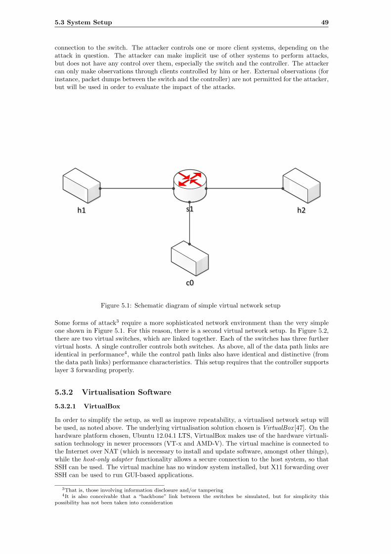
5.3 System Setup 49
connection to the switch. The attacker controls one or more client systems, depending on theattack in question. The attacker can make implicit use of other systems to perform attacks,but does not have any control over them, especially the switch and the controller. The attackercan only make observations through clients controlled by him or her. External observations (forinstance, packet dumps between the switch and the controller) are not permitted for the attacker,but will be used in order to evaluate the impact of the attacks.
h1h1 h2h2
c0c0
s1s1
Figure 5.1: Schematic diagram of simple virtual network setup
Some forms of attack3 require a more sophisticated network environment than the very simpleone shown in Figure 5.1. For this reason, there is a second virtual network setup. In Figure 5.2,there are two virtual switches, which are linked together. Each of the switches has three furthervirtual hosts. A single controller controls both switches. As above, all of the data path links areidentical in performance4, while the control path links also have identical and distinctive (fromthe data path links) performance characteristics. This setup requires that the controller supportslayer 3 forwarding properly.
5.3.2 Virtualisation Software
5.3.2.1 VirtualBox
In order to simplify the setup, as well as improve repeatability, a virtualised network setup willbe used, as noted above. The underlying virtualisation solution chosen is VirtualBox [47]. On thehardware platform chosen, Ubuntu 12.04.1 LTS, VirtualBox makes use of the hardware virtuali-sation technology in newer processors (VT-x and AMD-V). The virtual machine is connected tothe Internet over NAT (which is necessary to install and update software, amongst other things),while the host-only adapter functionality allows a secure connection to the host system, so thatSSH can be used. The virtual machine has no window system installed, but X11 forwarding overSSH can be used to run GUI-based applications.
3That is, those involving information disclosure and/or tampering4It is also conceivable that a “backbone” link between the switches be simulated, but for simplicity this
possibility has not been taken into consideration
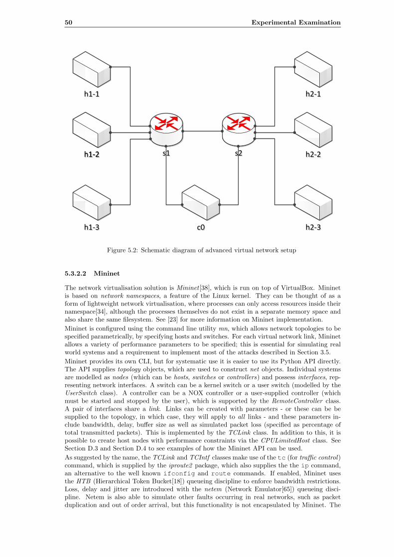
50 Experimental Examination
h1-1h1-1 h2-1h2-1
c0c0
s1s1 s2s2
h1-3h1-3 h2-3h2-3
h1-2h1-2h1-2h1-2 h2-2h2-2
Figure 5.2: Schematic diagram of advanced virtual network setup
5.3.2.2 Mininet
The network virtualisation solution is Mininet [38], which is run on top of VirtualBox. Mininetis based on network namespaces, a feature of the Linux kernel. They can be thought of as aform of lightweight network virtualisation, where processes can only access resources inside theirnamespace[34], although the processes themselves do not exist in a separate memory space andalso share the same filesystem. See [23] for more information on Mininet implementation.
Mininet is configured using the command line utility mn, which allows network topologies to bespecified parametrically, by specifying hosts and switches. For each virtual network link, Mininetallows a variety of performance parameters to be specified; this is essential for simulating realworld systems and a requirement to implement most of the attacks described in Section 3.5.
Mininet provides its own CLI, but for systematic use it is easier to use its Python API directly.The API supplies topology objects, which are used to construct net objects. Individual systemsare modelled as nodes (which can be hosts, switches or controllers) and possess interfaces, rep-resenting network interfaces. A switch can be a kernel switch or a user switch (modelled by theUserSwitch class). A controller can be a NOX controller or a user-supplied controller (whichmust be started and stopped by the user), which is supported by the RemoteController class.A pair of interfaces share a link. Links can be created with parameters - or these can be besupplied to the topology, in which case, they will apply to all links - and these parameters in-clude bandwidth, delay, buffer size as well as simulated packet loss (specified as percentage oftotal transmitted packets). This is implemented by the TCLink class. In addition to this, it ispossible to create host nodes with performance constraints via the CPULimitedHost class. SeeSection D.3 and Section D.4 to see examples of how the Mininet API can be used.
As suggested by the name, the TCLink and TCIntf classes make use of the tc (for traffic control)command, which is supplied by the iproute2 package, which also supplies the the ip command,an alternative to the well known ifconfig and route commands. If enabled, Mininet usesthe HTB (Hierarchical Token Bucket[18]) queueing discipline to enforce bandwidth restrictions.Loss, delay and jitter are introduced with the netem (Network Emulator[65]) queueing disci-pline. Netem is also able to simulate other faults occurring in real networks, such as packetduplication and out of order arrival, but this functionality is not encapsulated by Mininet. The
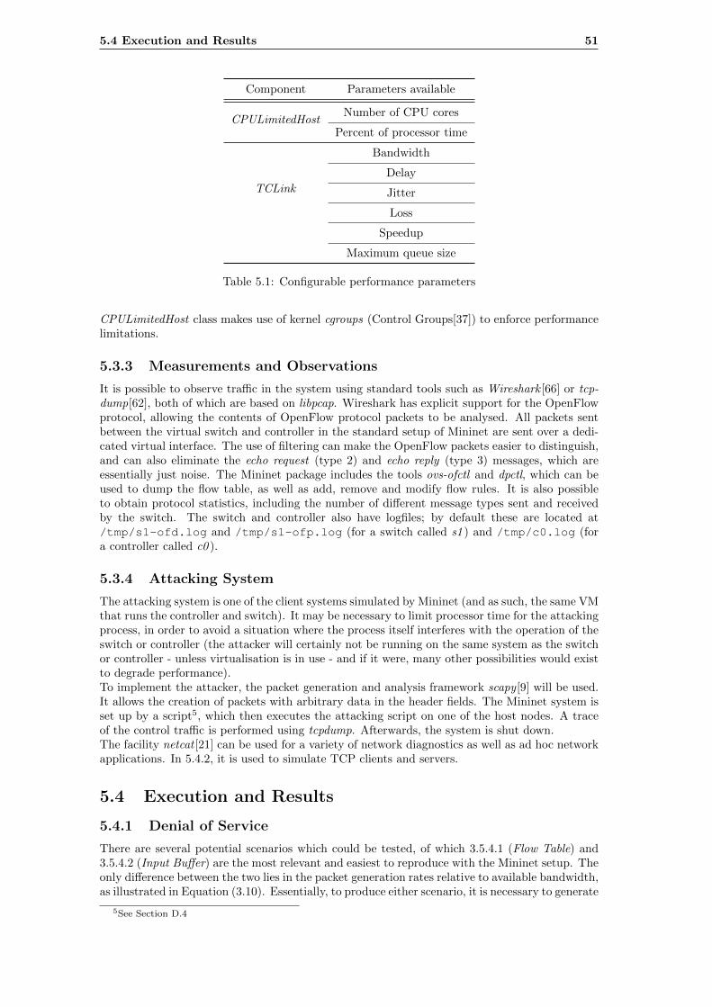
5.4 Execution and Results 51
Component Parameters available
CPULimitedHostNumber of CPU cores
Percent of processor time
TCLink
Bandwidth
Delay
Jitter
Loss
Speedup
Maximum queue size
Table 5.1: Configurable performance parameters
CPULimitedHost class makes use of kernel cgroups (Control Groups[37]) to enforce performancelimitations.
5.3.3 Measurements and Observations
It is possible to observe traffic in the system using standard tools such as Wireshark [66] or tcp-dump[62], both of which are based on libpcap. Wireshark has explicit support for the OpenFlowprotocol, allowing the contents of OpenFlow protocol packets to be analysed. All packets sentbetween the virtual switch and controller in the standard setup of Mininet are sent over a dedi-cated virtual interface. The use of filtering can make the OpenFlow packets easier to distinguish,and can also eliminate the echo request (type 2) and echo reply (type 3) messages, which areessentially just noise. The Mininet package includes the tools ovs-ofctl and dpctl, which can beused to dump the flow table, as well as add, remove and modify flow rules. It is also possibleto obtain protocol statistics, including the number of different message types sent and receivedby the switch. The switch and controller also have logfiles; by default these are located at/tmp/s1-ofd.log and /tmp/s1-ofp.log (for a switch called s1 ) and /tmp/c0.log (fora controller called c0 ).
5.3.4 Attacking System
The attacking system is one of the client systems simulated by Mininet (and as such, the same VMthat runs the controller and switch). It may be necessary to limit processor time for the attackingprocess, in order to avoid a situation where the process itself interferes with the operation of theswitch or controller (the attacker will certainly not be running on the same system as the switchor controller - unless virtualisation is in use - and if it were, many other possibilities would existto degrade performance).To implement the attacker, the packet generation and analysis framework scapy [9] will be used.It allows the creation of packets with arbitrary data in the header fields. The Mininet system isset up by a script5, which then executes the attacking script on one of the host nodes. A traceof the control traffic is performed using tcpdump. Afterwards, the system is shut down.The facility netcat [21] can be used for a variety of network diagnostics as well as ad hoc networkapplications. In 5.4.2, it is used to simulate TCP clients and servers.
5.4 Execution and Results
5.4.1 Denial of Service
There are several potential scenarios which could be tested, of which 3.5.4.1 (Flow Table) and3.5.4.2 (Input Buffer) are the most relevant and easiest to reproduce with the Mininet setup. Theonly difference between the two lies in the packet generation rates relative to available bandwidth,as illustrated in Equation (3.10). Essentially, to produce either scenario, it is necessary to generate
5See Section D.4
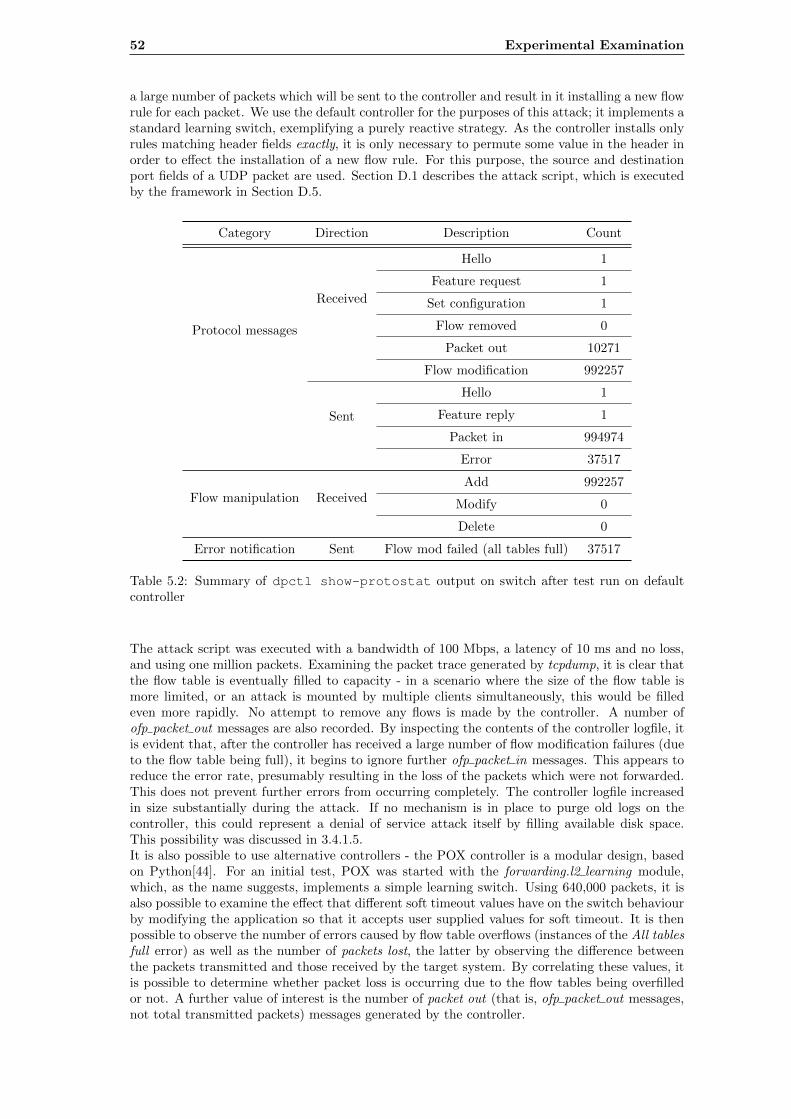
52 Experimental Examination
a large number of packets which will be sent to the controller and result in it installing a new flowrule for each packet. We use the default controller for the purposes of this attack; it implements astandard learning switch, exemplifying a purely reactive strategy. As the controller installs onlyrules matching header fields exactly, it is only necessary to permute some value in the header inorder to effect the installation of a new flow rule. For this purpose, the source and destinationport fields of a UDP packet are used. Section D.1 describes the attack script, which is executedby the framework in Section D.5.
Category Direction Description Count
Protocol messages
Received
Hello 1
Feature request 1
Set configuration 1
Flow removed 0
Packet out 10271
Flow modification 992257
Sent
Hello 1
Feature reply 1
Packet in 994974
Error 37517
Flow manipulation ReceivedAdd 992257
Modify 0
Delete 0
Error notification Sent Flow mod failed (all tables full) 37517
Table 5.2: Summary of dpctl show-protostat output on switch after test run on defaultcontroller
The attack script was executed with a bandwidth of 100 Mbps, a latency of 10 ms and no loss,and using one million packets. Examining the packet trace generated by tcpdump, it is clear thatthe flow table is eventually filled to capacity - in a scenario where the size of the flow table ismore limited, or an attack is mounted by multiple clients simultaneously, this would be filledeven more rapidly. No attempt to remove any flows is made by the controller. A number ofofp packet out messages are also recorded. By inspecting the contents of the controller logfile, itis evident that, after the controller has received a large number of flow modification failures (dueto the flow table being full), it begins to ignore further ofp packet in messages. This appears toreduce the error rate, presumably resulting in the loss of the packets which were not forwarded.This does not prevent further errors from occurring completely. The controller logfile increasedin size substantially during the attack. If no mechanism is in place to purge old logs on thecontroller, this could represent a denial of service attack itself by filling available disk space.This possibility was discussed in 3.4.1.5.It is also possible to use alternative controllers - the POX controller is a modular design, basedon Python[44]. For an initial test, POX was started with the forwarding.l2 learning module,which, as the name suggests, implements a simple learning switch. Using 640,000 packets, it isalso possible to examine the effect that different soft timeout values have on the switch behaviourby modifying the application so that it accepts user supplied values for soft timeout. It is thenpossible to observe the number of errors caused by flow table overflows (instances of the All tablesfull error) as well as the number of packets lost, the latter by observing the difference betweenthe packets transmitted and those received by the target system. By correlating these values, itis possible to determine whether packet loss is occurring due to the flow tables being overfilledor not. A further value of interest is the number of packet out (that is, ofp packet out messages,not total transmitted packets) messages generated by the controller.
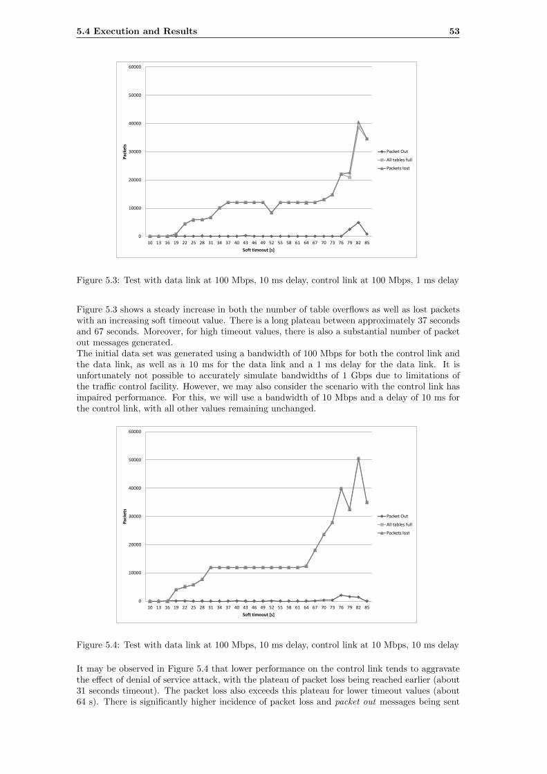
5.4 Execution and Results 53
10 13 16 19 22 25 28 31 34 37 40 43 46 49 52 55 58 61 64 67 70 73 76 79 82 85
0
10000
20000
30000
40000
50000
60000
Soft timeout [s]
Pac
kets
Packet Out
All tables full
Packets lost
Figure 5.3: Test with data link at 100 Mbps, 10 ms delay, control link at 100 Mbps, 1 ms delay
Figure 5.3 shows a steady increase in both the number of table overflows as well as lost packetswith an increasing soft timeout value. There is a long plateau between approximately 37 secondsand 67 seconds. Moreover, for high timeout values, there is also a substantial number of packetout messages generated.The initial data set was generated using a bandwidth of 100 Mbps for both the control link andthe data link, as well as a 10 ms for the data link and a 1 ms delay for the data link. It isunfortunately not possible to accurately simulate bandwidths of 1 Gbps due to limitations ofthe traffic control facility. However, we may also consider the scenario with the control link hasimpaired performance. For this, we will use a bandwidth of 10 Mbps and a delay of 10 ms forthe control link, with all other values remaining unchanged.
10 13 16 19 22 25 28 31 34 37 40 43 46 49 52 55 58 61 64 67 70 73 76 79 82 85
0
10000
20000
30000
40000
50000
60000
Soft timeout [s]
Pac
kets
Packet Out
All tables full
Packets lost
Figure 5.4: Test with data link at 100 Mbps, 10 ms delay, control link at 10 Mbps, 10 ms delay
It may be observed in Figure 5.4 that lower performance on the control link tends to aggravatethe effect of denial of service attack, with the plateau of packet loss being reached earlier (about31 seconds timeout). The packet loss also exceeds this plateau for lower timeout values (about64 s). There is significantly higher incidence of packet loss and packet out messages being sent
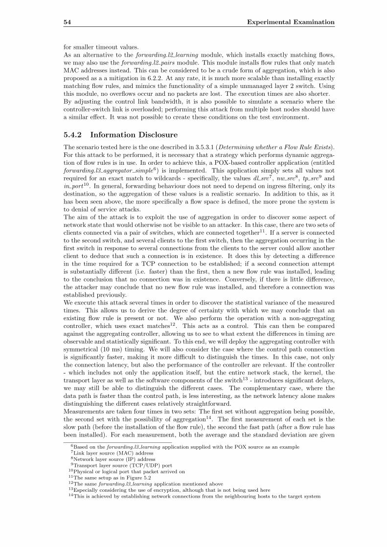
54 Experimental Examination
for smaller timeout values.As an alternative to the forwarding.l2 learning module, which installs exactly matching flows,we may also use the forwarding.l2 pairs module. This module installs flow rules that only matchMAC addresses instead. This can be considered to be a crude form of aggregation, which is alsoproposed as a a mitigation in 6.2.2. At any rate, it is much more scalable than installing exactlymatching flow rules, and mimics the functionality of a simple unmanaged layer 2 switch. Usingthis module, no overflows occur and no packets are lost. The execution times are also shorter.By adjusting the control link bandwidth, it is also possible to simulate a scenario where thecontroller-switch link is overloaded; performing this attack from multiple host nodes should havea similar effect. It was not possible to create these conditions on the test environment.
5.4.2 Information Disclosure
The scenario tested here is the one described in 3.5.3.1 (Determining whether a Flow Rule Exists).For this attack to be performed, it is necessary that a strategy which performs dynamic aggrega-tion of flow rules is in use. In order to achieve this, a POX-based controller application (entitledforwarding.l3 aggregator simple6) is implemented. This application simply sets all values notrequired for an exact match to wildcards - specifically, the values dl src7, nw src8, tp src9 andin port10. In general, forwarding behaviour does not need to depend on ingress filtering, only itsdestination, so the aggregation of these values is a realistic scenario. In addition to this, as ithas been seen above, the more specifically a flow space is defined, the more prone the system isto denial of service attacks.The aim of the attack is to exploit the use of aggregation in order to discover some aspect ofnetwork state that would otherwise not be visible to an attacker. In this case, there are two sets ofclients connected via a pair of switches, which are connected together11. If a server is connectedto the second switch, and several clients to the first switch, then the aggregation occurring in thefirst switch in response to several connections from the clients to the server could allow anotherclient to deduce that such a connection is in existence. It does this by detecting a differencein the time required for a TCP connection to be established; if a second connection attemptis substantially different (i.e. faster) than the first, then a new flow rule was installed, leadingto the conclusion that no connection was in existence. Conversely, if there is little difference,the attacker may conclude that no new flow rule was installed, and therefore a connection wasestablished previously.We execute this attack several times in order to discover the statistical variance of the measuredtimes. This allows us to derive the degree of certainty with which we may conclude that anexisting flow rule is present or not. We also perform the operation with a non-aggregatingcontroller, which uses exact matches12. This acts as a control. This can then be comparedagainst the aggregating controller, allowing us to see to what extent the differences in timing areobservable and statistically significant. To this end, we will deploy the aggregating controller withsymmetrical (10 ms) timing. We will also consider the case where the control path connectionis significantly faster, making it more difficult to distinguish the times. In this case, not onlythe connection latency, but also the performance of the controller are relevant. If the controller- which includes not only the application itself, but the entire network stack, the kernel, thetransport layer as well as the software components of the switch13 - introduces significant delays,we may still be able to distinguish the different cases. The complementary case, where thedata path is faster than the control path, is less interesting, as the network latency alone makesdistinguishing the different cases relatively straightforward.Measurements are taken four times in two sets: The first set without aggregation being possible,the second set with the possibility of aggregation14. The first measurement of each set is theslow path (before the installation of the flow rule), the second the fast path (after a flow rule hasbeen installed). For each measurement, both the average and the standard deviation are given
6Based on the forwarding.l3 learning application supplied with the POX source as an example7Link layer source (MAC) address8Network layer source (IP) address9Transport layer source (TCP/UDP) port
10Physical or logical port that packet arrived on11The same setup as in Figure 5.212The same forwarding.l3 learning application mentioned above13Especially considering the use of encryption, although that is not being used here14This is achieved by establishing network connections from the neighbouring hosts to the target system
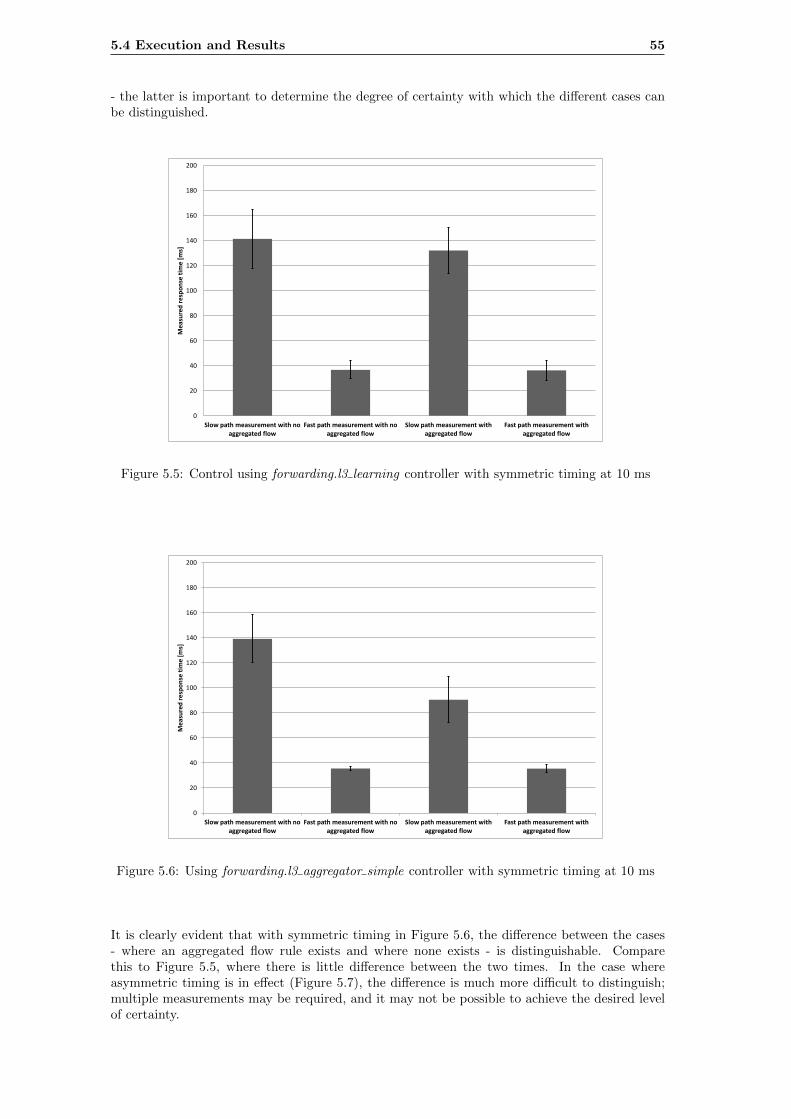
5.4 Execution and Results 55
- the latter is important to determine the degree of certainty with which the different cases canbe distinguished.
Slow path measurement with no aggregated flow
Fast path measurement with no aggregated flow
Slow path measurement with aggregated flow
Fast path measurement with aggregated flow
0
20
40
60
80
100
120
140
160
180
200
Mea
sure
d r
esp
on
se t
ime
[ms]
Figure 5.5: Control using forwarding.l3 learning controller with symmetric timing at 10 ms
Slow path measurement with no aggregated flow
Fast path measurement with no aggregated flow
Slow path measurement with aggregated flow
Fast path measurement with aggregated flow
0
20
40
60
80
100
120
140
160
180
200
Mea
sure
d r
esp
on
se t
ime
[ms]
Figure 5.6: Using forwarding.l3 aggregator simple controller with symmetric timing at 10 ms
It is clearly evident that with symmetric timing in Figure 5.6, the difference between the cases- where an aggregated flow rule exists and where none exists - is distinguishable. Comparethis to Figure 5.5, where there is little difference between the two times. In the case whereasymmetric timing is in effect (Figure 5.7), the difference is much more difficult to distinguish;multiple measurements may be required, and it may not be possible to achieve the desired levelof certainty.
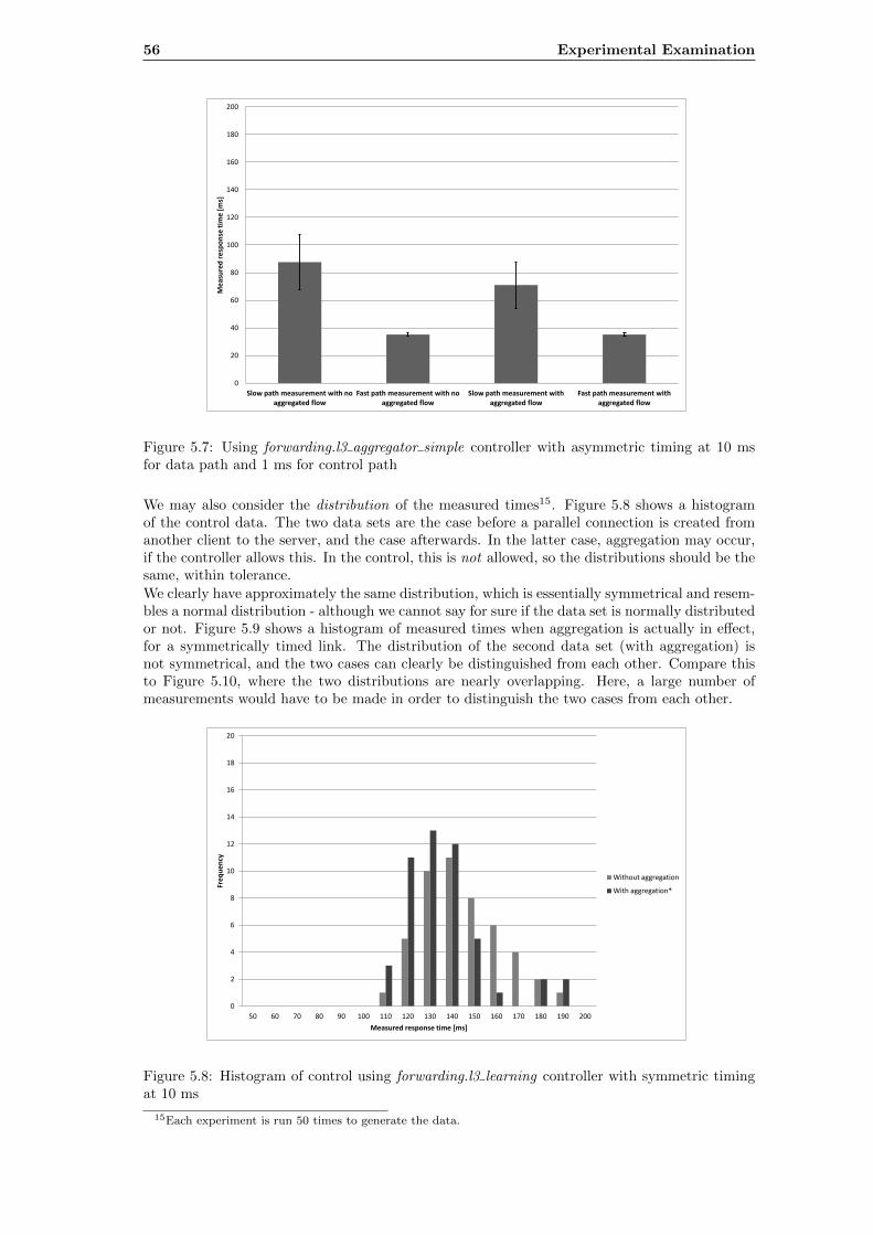
56 Experimental Examination
Slow path measurement with no aggregated flow
Fast path measurement with no aggregated flow
Slow path measurement with aggregated flow
Fast path measurement with aggregated flow
0
20
40
60
80
100
120
140
160
180
200
Me
asu
red
re
spo
nse
tim
e [
ms]
Figure 5.7: Using forwarding.l3 aggregator simple controller with asymmetric timing at 10 msfor data path and 1 ms for control path
We may also consider the distribution of the measured times15. Figure 5.8 shows a histogramof the control data. The two data sets are the case before a parallel connection is created fromanother client to the server, and the case afterwards. In the latter case, aggregation may occur,if the controller allows this. In the control, this is not allowed, so the distributions should be thesame, within tolerance.
We clearly have approximately the same distribution, which is essentially symmetrical and resem-bles a normal distribution - although we cannot say for sure if the data set is normally distributedor not. Figure 5.9 shows a histogram of measured times when aggregation is actually in effect,for a symmetrically timed link. The distribution of the second data set (with aggregation) isnot symmetrical, and the two cases can clearly be distinguished from each other. Compare thisto Figure 5.10, where the two distributions are nearly overlapping. Here, a large number ofmeasurements would have to be made in order to distinguish the two cases from each other.
0
2
4
6
8
10
12
14
16
18
20
50 60 70 80 90 100 110 120 130 140 150 160 170 180 190 200
Freq
uen
cy
Measured response time [ms]
Without aggregation
With aggregation*
Figure 5.8: Histogram of control using forwarding.l3 learning controller with symmetric timingat 10 ms
15Each experiment is run 50 times to generate the data.
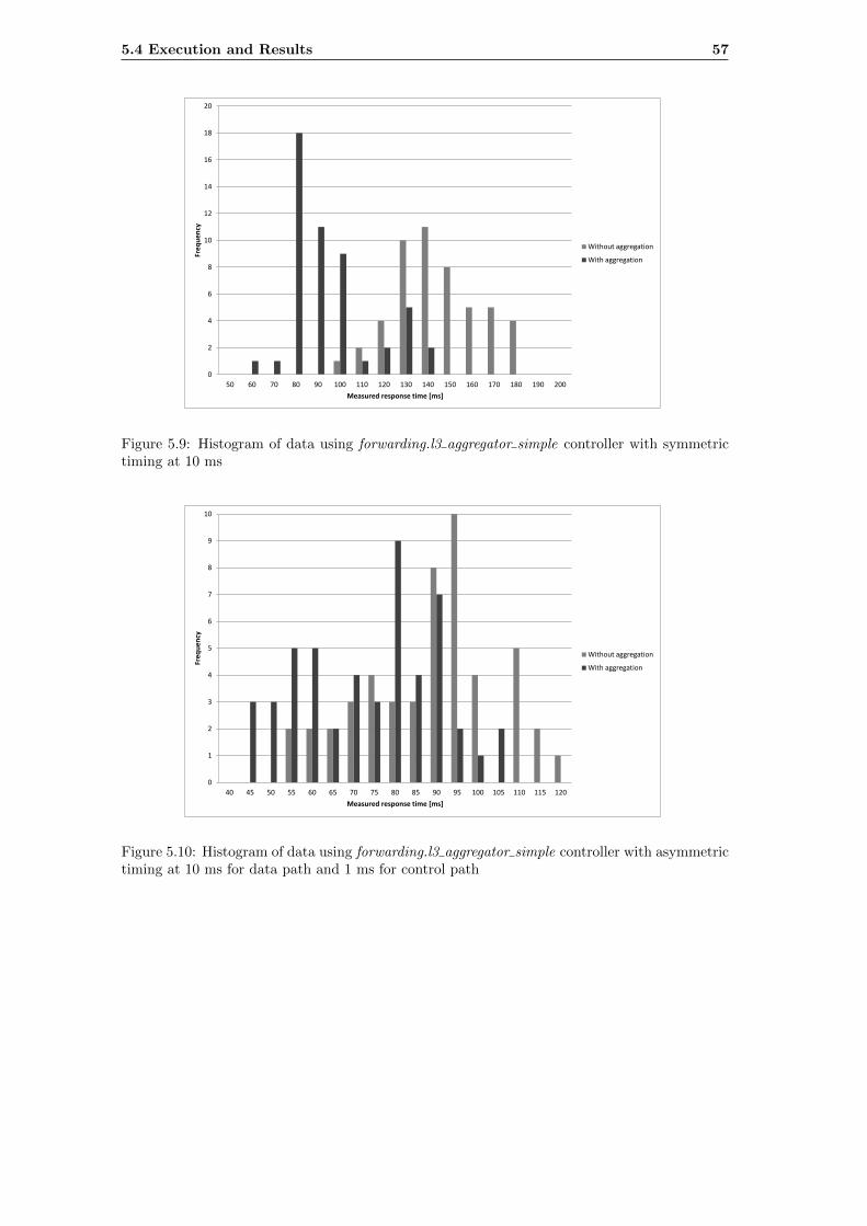
5.4 Execution and Results 57
50 60 70 80 90 100 110 120 130 140 150 160 170 180 190 200
0
2
4
6
8
10
12
14
16
18
20
Measured response time [ms]
Fre
qu
ency
Without aggregation
With aggregation
Figure 5.9: Histogram of data using forwarding.l3 aggregator simple controller with symmetrictiming at 10 ms
40 45 50 55 60 65 70 75 80 85 90 95 100 105 110 115 120
0
1
2
3
4
5
6
7
8
9
10
Measured response time [ms]
Freq
ue
ncy
Without aggregation
With aggregation
Figure 5.10: Histogram of data using forwarding.l3 aggregator simple controller with asymmetrictiming at 10 ms for data path and 1 ms for control path
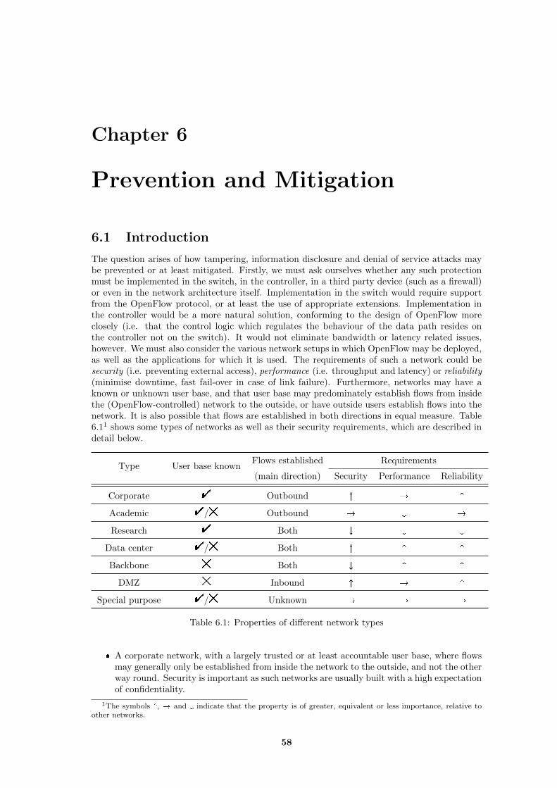
Chapter 6
Prevention and Mitigation
6.1 Introduction
The question arises of how tampering, information disclosure and denial of service attacks maybe prevented or at least mitigated. Firstly, we must ask ourselves whether any such protectionmust be implemented in the switch, in the controller, in a third party device (such as a firewall)or even in the network architecture itself. Implementation in the switch would require supportfrom the OpenFlow protocol, or at least the use of appropriate extensions. Implementation inthe controller would be a more natural solution, conforming to the design of OpenFlow moreclosely (i.e. that the control logic which regulates the behaviour of the data path resides onthe controller not on the switch). It would not eliminate bandwidth or latency related issues,however. We must also consider the various network setups in which OpenFlow may be deployed,as well as the applications for which it is used. The requirements of such a network could besecurity (i.e. preventing external access), performance (i.e. throughput and latency) or reliability(minimise downtime, fast fail-over in case of link failure). Furthermore, networks may have aknown or unknown user base, and that user base may predominately establish flows from insidethe (OpenFlow-controlled) network to the outside, or have outside users establish flows into thenetwork. It is also possible that flows are established in both directions in equal measure. Table6.11 shows some types of networks as well as their security requirements, which are described indetail below.
Type User base knownFlows established Requirements
(main direction) Security Performance Reliability
Corporate " Outbound ^ � ^
Academic "/# Outbound � _ �
Research " Both _ _ _
Data center "/# Both ^ ^ ^
Backbone # Both _ ^ ^
DMZ # Inbound ^ � ^
Special purpose "/# Unknown � � �
Table 6.1: Properties of different network types
� A corporate network, with a largely trusted or at least accountable user base, where flowsmay generally only be established from inside the network to the outside, and not the otherway round. Security is important as such networks are usually built with a high expectationof confidentiality.
1The symbols ^, � and _ indicate that the property is of greater, equivalent or less importance, relative toother networks.
58
6.1 Introduction 59
� An academic network, with a well-defined, but not necessarily trustworthy user base2.Access control has a lower emphasis, and users may decide to run ad-hoc servers. It is alsopossible that users will execute applications which generate very heavy network traffic, forexperimental or other purposes.
� A research network, established for the sole purposes of research into network-based ap-plications (Chapter 5 presents an example). The requirements are low, as both trafficand access are controlled by the researcher(s). However, it is necessary for the networkto support a wide range of functionality, and be easily programmable. This also appliesto networks used for development in a corporate environment. This network environmentgenerally does not present a security risk.
� A backbone network, which handles large amounts of traffic. The user base is unknownand is not considered trustworthy. Network flows may be established in any direction.Performance is most important with little expectation of security, in the sense that theconfidentiality and integrity of data being transmitted in the network is not guaranteed.The impact of attacks affecting availability and throughput is very high - these aspects aresubsumed under reliability and performance, respectively.
� A data center network, which may have heavy traffic loads but also have multiple pathwaysand high degrees of redundancy.
� A demilitarised zone (DMZ), which sits on the boundary of a controlled network environ-ment and the Internet. It is essential that systems here are accessible from the outside,and with reasonable performance, but access needs to be controlled for security reasons. Itcan be considered a special case of a data center network (a DMZ is usually situated in adata center).
� A hermetically isolated, single purpose network with no connection to the Internet at large.Such a network could be a virtual network or a physical one. An example of the latterwould be networks used for Internet telephony and television. Research networks wouldalso fall into this category. Security is not a major concern at a network level, although careshould be taken in case an unauthorised system connects to the network. These networksmay have special requirements or make use of extensions, like virtual network slices ormulticasting.
Proposed applications for OpenFlow networks include (with remarks about requirements oncontroller strategy):
� Switching and routing3, especially unconventional routing methods[16]. Many of theseapplications introduce a dynamic element to routing and switching (as opposed to a staticforwarding table), making a proactive strategy less effective. OpenFlow can also be used toimplement static routing, which can be completely proactive in nature - this is a requirementin backbone networks and desirable for data center networks. In general, all networksrequire some form of forwarding, and this constitutes the most basic functionality offeredby OpenFlow.
� Multicasting and other media distribution methods[40, 33]. The central coordination inher-ent in the OpenFlow design can make multicast routing considerably easier to implement.Multicasting can be sort of as“subscription”to“published”content (in the case of a commonapplication of multicasting, IPTV, this analogy is quite evident). Since the subscriptioncannot be predicted in advance, the system is inherently reactive in nature. Although thismay be used in some corporate or academic networks, the main use is in backbone networks(where the performance advantages are most notable) and special purpose networks.
� Access control, that is, the application of access control lists to the establishment of newflows[73, 74]. This system is reactive in nature, although a flow rule can be installed todrop traffic that is not permitted. The use of OpenFlow for enforcing security policies
2Not trustworthy in the sense that, if there are any security weaknesses, they may be exploited for comparativelybenign purposes.
3Strictly speaking, the OpenFlow 1.0 specification is not capable of acting as a network layer switch, as it doesnot support decrementing the TTL field of the IP header.
60 Prevention and Mitigation
requires careful consideration: There is a trade-off between granularity and performance.This approach would be used in lieu of a firewall in a corporate network or other networkrequiring stringent access control. Use on a data center is conceivable, but would requirecareful consideration of the trade-offs between security and performance. Some form ofaccess control may also be desirable for a DMZ network.
� Load balancing[70]. One example would be to split flows randomly between targets, withthe probability of each target being chosen inversely proportional to the current load. Thiswould be applied by the controller, leading to a reactive strategy. With OpenFlow 1.2,this could be implemented proactively, as OpenFlow 1.2 has some in-built support for loadbalancing. Load balancing would be most applicable to a DMZ or data center network.
� Fail-over and reliability[61, 17, 75]. This functionality does not need to have an influenceon controller strategy: It is only necessary for the controller to react if connectivity is lostor degraded (which the controller will learn from a port status message or similar). Thecontroller can then modify the flow table as needed. Newer versions of OpenFlow alsosupport fast fail-over, allowing the switch to change routes without the controller interven-ing. See also Section 4.4. This practice is most applicable to data center and backbonenetworks, which actually have multiple paths available; most network types usually usespanning tree-based forwarding as the simplest loop-free strategy.
� Traffic shaping and other peformance-related policy enforcement. As with other dynamicforwarding strategies, the most flexibility is obtained when using a reactive strategy, al-though (especially with OpenFlow 1.3, see Section 4.4) there is some support in the protocolfor traffic shaping through flow meters and QoS, which may be installed in advance withbroadly applicable flow rules (assuming multiple flow tables are available). These may beemployed in a corporate or academic network to enable performance-sensitive applications(videoconferencing or IP telephony, for instance), or on a data center to enforce trafficpolicies and ensure that all users receive a certain level of service; this may be stipulatedin service-level agreement. The application in backbone networks is highly controversial4.
� Enforcement of power consumption policy[68]. This highly specific application is proactivein nature, but can be implemented on a system using reactive strategies. The proposedapplication is focused on data center networks and may also apply to DMZ networks (whichare essentially a similar case).
� Network virtualisation and isolation[53, 57, 60]. In the case of FlowVisor, this is actuallyenforced by an intermediate system between the switch and the controller. In general thepresence of virtualisation does not need to dictate a particular controller strategy, but willmake the effects of such a strategy harder to predict. Data center networks are of particularinterest, but academic and corporate networks are also relevant. Virtualisation is importantfor research networks, especially when separating these from production networks; thisconstituted the original purpose of the FlowVisor extension.
� Monitoring and instrumentation[35, 10, 36]. Beyond the counters supplied by the Open-Flow protocol, this could include a controller application (which monitors new flows) or asystem receiving mirrored traffic. All types of networks may benefit from more detailedmonitoring, but those with heavy, unpredictable traffic are of particular interest: Back-bone, data center and DMZ networks, as well as research networks where instrumentationmay be a requirement.
6.2 Denial of Service
With the above points in mind, several approaches are conceivable for mitigating denial of serviceattacks. These are summarised in Table 6.2 and subsequently described in detail.
4The use of traffic shaping and similar measures may be considered to violate network neutrality
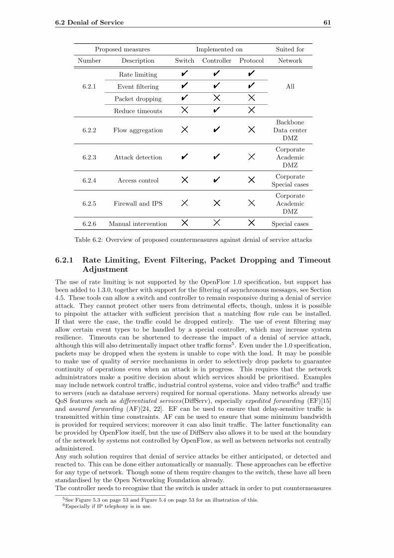
6.2 Denial of Service 61
Proposed measures Implemented on Suited for
Number Description Switch Controller Protocol Network
6.2.1
Rate limiting " " "
AllEvent filtering " " "
Packet dropping " # #
Reduce timeouts # " #
6.2.2 Flow aggregation # " #
BackboneData center
DMZ
6.2.3 Attack detection " " #
CorporateAcademic
DMZ
6.2.4 Access control # " #Corporate
Special cases
6.2.5 Firewall and IPS # # #
CorporateAcademic
DMZ
6.2.6 Manual intervention # # # Special cases
Table 6.2: Overview of proposed countermeasures against denial of service attacks
6.2.1 Rate Limiting, Event Filtering, Packet Dropping and TimeoutAdjustment
The use of rate limiting is not supported by the OpenFlow 1.0 specification, but support hasbeen added to 1.3.0, together with support for the filtering of asynchronous messages, see Section4.5. These tools can allow a switch and controller to remain responsive during a denial of serviceattack. They cannot protect other users from detrimental effects, though, unless it is possibleto pinpoint the attacker with sufficient precision that a matching flow rule can be installed.If that were the case, the traffic could be dropped entirely. The use of event filtering mayallow certain event types to be handled by a special controller, which may increase systemresilience. Timeouts can be shortened to decrease the impact of a denial of service attack,although this will also detrimentally impact other traffic forms5. Even under the 1.0 specification,packets may be dropped when the system is unable to cope with the load. It may be possibleto make use of quality of service mechanisms in order to selectively drop packets to guaranteecontinuity of operations even when an attack is in progress. This requires that the networkadministrators make a positive decision about which services should be prioritised. Examplesmay include network control traffic, industrial control systems, voice and video traffic6 and trafficto servers (such as database servers) required for normal operations. Many networks already useQoS features such as differentiated services(DiffServ), especially expedited forwarding (EF)[15]and assured forwarding (AF)[24, 22]. EF can be used to ensure that delay-sensitive traffic istransmitted within time constraints. AF can be used to ensure that some minimum bandwidthis provided for required services; moreover it can also limit traffic. The latter functionality canbe provided by OpenFlow itself, but the use of DiffServ also allows it to be used at the boundaryof the network by systems not controlled by OpenFlow, as well as between networks not centrallyadministered.Any such solution requires that denial of service attacks be either anticipated, or detected andreacted to. This can be done either automatically or manually. These approaches can be effectivefor any type of network. Though some of them require changes to the switch, these have all beenstandardised by the Open Networking Foundation already.The controller needs to recognise that the switch is under attack in order to put countermeasures
5See Figure 5.3 on page 53 and Figure 5.4 on page 53 for an illustration of this.6Especially if IP telephony is in use.
62 Prevention and Mitigation
into effect, unless they are permanently in place. Identifying the source of the attack is notnecessary, and probably not feasible, given that IP and/or MAC spoofing may be in effect. Therecognition would instead recognise that a certain acceptable level of traffic has been exceededand react accordingly. This is discussed in 6.2.3.
6.2.2 Flow Aggregation
Flow aggregation is a controller strategy where one flow rule matches multiple network flows.This can help to reduce the number of flow rules required to match network traffic. The reductionin flow rules comes at the expense of precision. It also introduces the possibility of unintendedconsequences - aggregated flow rules would also affect users of other systems - if the aggregationis performed automatically7. For networks that do not require precise control of flows, this maybe an effective approach. The enforcement of security policies would be more limited, but thiswould have no impact if these were not enforced in the OpenFlow network itself - making thisapproach attractive for backbone networks and others which have heavy traffic. A fully proactiveapproach where flow rules cover all possible traffic would be the logical extreme. That wouldduplicate the functionality of conventional forwarding tables, but allow more flexibility in termsof matching capability and allowing routing to be performed from a single centralised system.This approach notably does not require any changes to be made to the OpenFlow protocol orswitch and can be implemented solely on the controller. It also does not require any sophisticateddetection heuristics, although setting up the flow table in a proactive manner is more advancedthan a simpler reactive strategy. The switch can be configured to drop packets by default ratherthan forwarding them to the controller. The extent to which the issue of denial of service attacksis mitigated depends on the degree of aggregation. We might define this as the number of effectivenew flows (a flow being the tuple of source address, destination address, source port, destinationport and transport protocol) per installed flow rule. The higher the value is, the closer the systemis to a proactive strategy and the less vulnerable it is to denial of service attack against the flowtable, input buffer or controller. A fully proactive strategy, where packets are never forwardedto the controller, is immune to this type of attack.
6.2.3 Attack Detection
Automatic detection of denial of service attacks (for instance, through anomaly detection) is anarea that has received considerable attention and remains a major research topic regardless ofits impact on software defined networking - for examples, see [32, 54, 64, 12]. Such a detectionalgorithm could at the least establish that an attack is in progress, perhaps allowing the controllerto configure the switch to reduce the impact via rate limiting, reduction of soft timeout orprioritisation of certain traffic classes (all measures discussed in 6.2.1). System administratorscould also be notified. A more advanced solution could allow such attacks to be characterised, inorder to discover their origin and possibly to allow more precise measures to be taken to reducetheir impact, such as barring traffic meeting certain criteria. This may also be of use in the eventthat involvement of law enforcement agencies is desired, allowing incriminating traffic to besent to a recording system, perhaps a honey-pot. This approach does not counteract an attackby itself, but may be part of an automated security system that is used to direct forwardingbehaviour.Basic detection functionality could be implemented as a controller application - essentially anIPS application for the controller. The processing could be done in a different thread or processin an asynchronous manner. The flexible forwarding behaviour of OpenFlow would allow certaincategories of flows to be duplicated to monitoring systems, without interrupting the flow. Al-though this is possible with existing switching solutions, with OpenFlow this can be standardisedand made dynamic, with the monitoring system essentially subscribing to traffic that it wantsto receive. These approaches could be combined by selectively duplicating flows deemed to be“high risk” to an external monitoring system. The addition of OXM in 1.2 (see 4.4.2) makes itpossible that appropriate extensions could implement deep packet inspection at a relatively lowperformance cost. DPI would make the detection of malicious traffic considerably more feasible.Even then, detection solutions could already be implemented on the basis of the 1.0 specification- many make use only of network and transport layer headers.
7A rudimentary form of aggregation is demonstrated in 5.4.1.
6.3 Information Disclosure 63
6.2.4 Whitelisting and Access Control
A more drastic solution is the enforcement of an access control list, a “whitelist” approach, whichwould only allow traffic to and from permitted addresses and with permitted service types.This would require that all intended uses be foreseen, at least for in-bound traffic. Trafficoriginating from inside the trusted domain may be allowed to pass, similar to existing firewallsolutions. Whitelisting does not require special functionality on the part of the switch, nor does itrequire any changes to the protocol. This solution is worth considering for corporate or academicnetworks where most flows are likely to be instantiated either from internal addresses or fromtrusted external ones. This is also analogue to NAT solutions in widespread use8, which alsoallow outbound traffic and related inbound traffic to pass freely, without allowing connectionestablishment from the outside. This solution cannot be applied if outside access is required,which is most likely to be the case in a demilitarised zone (DMZ). It is clearly not viable forbackbone networks.
6.2.5 Firewall and IPS
Insofar as any attack originates outside a corporate or academic network, a firewall or IPS maybe of use to detect and filter traffic. These systems do not separate the user and control pathand therefore should be more robust under load, and they are already in widespread use, beingneeded to protect client systems from attacks. Such systems could also be used to enforce accesscontrol rules, although this reduces the utility of OpenFlow, which would no longer be solely incontrol of the network. The problem of detecting malicious traffic would still remain.
6.2.6 Manual Intervention
It should not be forgotten that, although these approaches function without any kind of manualintervention, many important networks are managed by network administrators; some networksare even under constant surveillance. If this is the case, it may be worth taking into considerationthat a network administrator can decide on an appropriate reaction more effectively than analgorithm can, albeit far more slowly. Manual intervention is most useful on controlled networks,especially those which are under continuous surveillance, and against attacks that continue for asubstantial period of time.
6.2.7 Hash Collision Prevention
This only applies to the very specific attack described in 3.5.4.1 involving hash collisions todegrade performance. A possible approach to preventing this form of attack is to introducerandomisation in some elements of the flow table entries, making them harder to predict andtherefore making it more difficult to find flow rules which collide. It also makes it impossibleto attempt to simulate flow rule creation on the attacker’s system. The cookie element is idealfor this purpose, since it is not required that its values be sequential. However, care mustbe taken, as the OpenFlow specification notes that the value need not be stored in hardware;therefore the cookie may have no influence on hashes used for hardware (TCAM) flow tables.Another possibility is to use varying values for timeouts. This may have the further advantageof making the switch behaviour less straightforward to predict. It is unfortunately also possiblethat the switch may not store timeout values in hardware either. If this is the case, an additionalcountermeasure could be to simulate the switch hash function on the controller, allowing itto detect hash collisions and take appropriate countermeasures, such as (possibly temporarily)refusing to install offending flow rules. Also, as above, the use of a proactive strategy preventsthis form of attack.
6.3 Information Disclosure
Information disclosure, arising from timing analysis, can reveal certain aspects of a network’sstate as well as controller strategy to an attacker. The aim of any prevention or mitigationstrategy is to ensure that any observable parameters of the system’s operation do not depend
8Of course, OpenFlow can itself be used to implement NAT
64 Prevention and Mitigation
on the internal system state, apart from those which are observable from the normal operationof the system. For instance, it may be observed whether or not a packet is forwarded; thisreveals some (small) information about the flow table and/or the controller’s strategy. It is notpossible to prevent this from being revealed, nor is this a weakness of the OpenFlow protocol(any system that enforces access to a resource can be probed in this way). However, if it ispossible to determine whether (for instance) a new flow rule is being installed in response to apacket that the user has sent, some information is revealed that is not required by the systemdesign, and not available to an attack against a more conventional system. There are severalpotential approaches to mitigating this issue. The suggestions made here are similar to proposedmitigations of side channel attacks in cryptographic systems[67, 52].
6.3.1 Proactive Strategy
As with 6.2.2, the use of a proactive strategy can prevent the occurrence of an issue by removingthe dependency of response time on the network state. This requires a fully proactive strategyto be effective. The use of flow aggregation, where one flow rule matches multiple flows but theflow rule is still installed in response to user-generated traffic, may actually make the situationworse, especially if source address aggregation9 is in use, as users might be able to determinewhether another user has been communicating with a given host.
6.3.2 Randomisation
By increasing the variance of measurable response times, any timing analysis technique may behindered. This strategy has been proposed to deal with timing attacks against cryptographicsystems such as RSA or AES. By increasing the statistical uncertainty, the number of samplesrequired in order to make assumptions about the system can be increased. This may makethe attack less feasible, and the obtained results less certain, although there will be a certainperformance penalty for introducing delays. Introducing random delays on the data path is farfrom straightforward; most hardware would not support this and the performance degradationmay be unacceptable.
6.3.3 Attack Detection
In analogy to 6.2.3, it may be possible to develop a controller application which detects suspicioustraffic. Any attack based on timing analysis (or any other form of side channel attack) is likelyto exhibit a distinctive, repetitive traffic pattern, which may be used by the controller to enactcountermeasures or to notify an administrator. A response could include dropping suspicioustraffic, introducing randomisation or changing strategy.
6.3.4 Enforced Equal Response Time
The use of equal response time for packets travelling over the switch and those being sent to thecontroller is obviously not desirable for performance reasons. This approach therefore particularlyapplies to attacks based on the difference in performance between the fast and the slow path ofthe switch - the part that is implemented in hardware and that which is implemented in software.Making the software component as fast as the hardware component is futile, as the hardwarecomponent can match header fields in parallel using TCAM and forward them to the outputqueue directly. It might be possible, however, to introduce a delay on the fast path to maskperformance differences. This would only need to be small, and would not necessarily constitutea bottleneck. It would also be necessary to introduce a stochastic element, as the software path isgenerally less predictable than the hardware component. This would require changes to hardwareand therefore may not be cost-effective, given the limited scope of this form of attack.
9That is, traffic from a range of source addresses to a destination (possibly also a range) is covered by one flowrule, which is cheaper in terms of flow table capacity if all packets would use the same port.
6.4 Tampering 65
6.4 Tampering
The tampering attacks described in 3.5.2 mostly revolve around a sort of cache poisoning, wherethe controller installs flow rules based on untrustworthy traffic. Due to the architecture of boththe IPv4 and IPv6 protocols, this untrustworthiness is inherent; the only way to prevent it wouldbe to introduce security mechanisms into DHCP, ARP, NDP and related protocols, which iscertainly not feasible due to extensive requirements for backward compatibility. This issue is notcaused by the OpenFlow protocol specifically, but the protocol allows such attacks to have moresevere effects, specifically due to the use of a reactive controller strategy. For this reason, all ofthe approaches described here involve only mitigating the issue to the point where it is no moreserious than the corresponding problems taking place within conventional networks.
6.4.1 Proactive Strategy
As with denial of service and information disclosure vulnerabilities, a proactive strategy here alsoalleviates the issue. This is due to the controller installing flow rules based on untrusted input. Aproactive strategy would emulate the functionality of a traditional switch; although the issue isnot prevented by such an approach, it is no more vulnerable than a regular network. A partiallyproactive strategy would partially mitigate the issue, depending on the form of aggregation thatis in use.
6.4.2 Timeouts
If flow rules are installed which have the effect of diverting traffic to a malicious user, thenshortening the timeout will have the effect of reducing the impact of the attack. This will forcean attacker to generate a larger number of forged packets, making the attack more likely to bedetected. If the timeout is unpredictable, an attacker will be unable to determine when a flowrule is removed due to timeout, again making this form of attack harder to execute and lesseffective.
6.4.3 Integrity Checking
A controller may also perform sanity checking on received ARP or NDP packets. Simple testscould be to check for conflicting ARP or NDP replies; under normal circumstances unicast IPaddresses should never be shared within their scope, so having multiple systems answer to a singlerequest must be considered suspicious. The same principle applies to MAC addresses, which bydefinition should be globally unique10, and so cannot appear on more than one port, unless thenetwork has multiple paths. The controller may have some information about network structure,for instance that a certain port is connected only to one subnet, or that a port is connected tosingle system, so that multiple IP addresses or MAC addresses cannot become assigned to it.
6.4.4 Access Control
An access control solution would involve the controller knowing the entire network topology andonly permitting the installation of flow rules which conform to policy. IP addresses must bemapped to permitted switch ports11. This solution is sound for a network which is constant incomposition, but is inconvenient if the network structure is likely to change. It does not scale tobackbone networks, but it may be of interest in corporate networks and other networks whichare centrally administered.
10This may not apply to administrator-assigned addresses, but then the administrator is responsible for ensuringuniqueness within a broadcast domain.
11Not MAC addresses, as these can trivially be forged as well
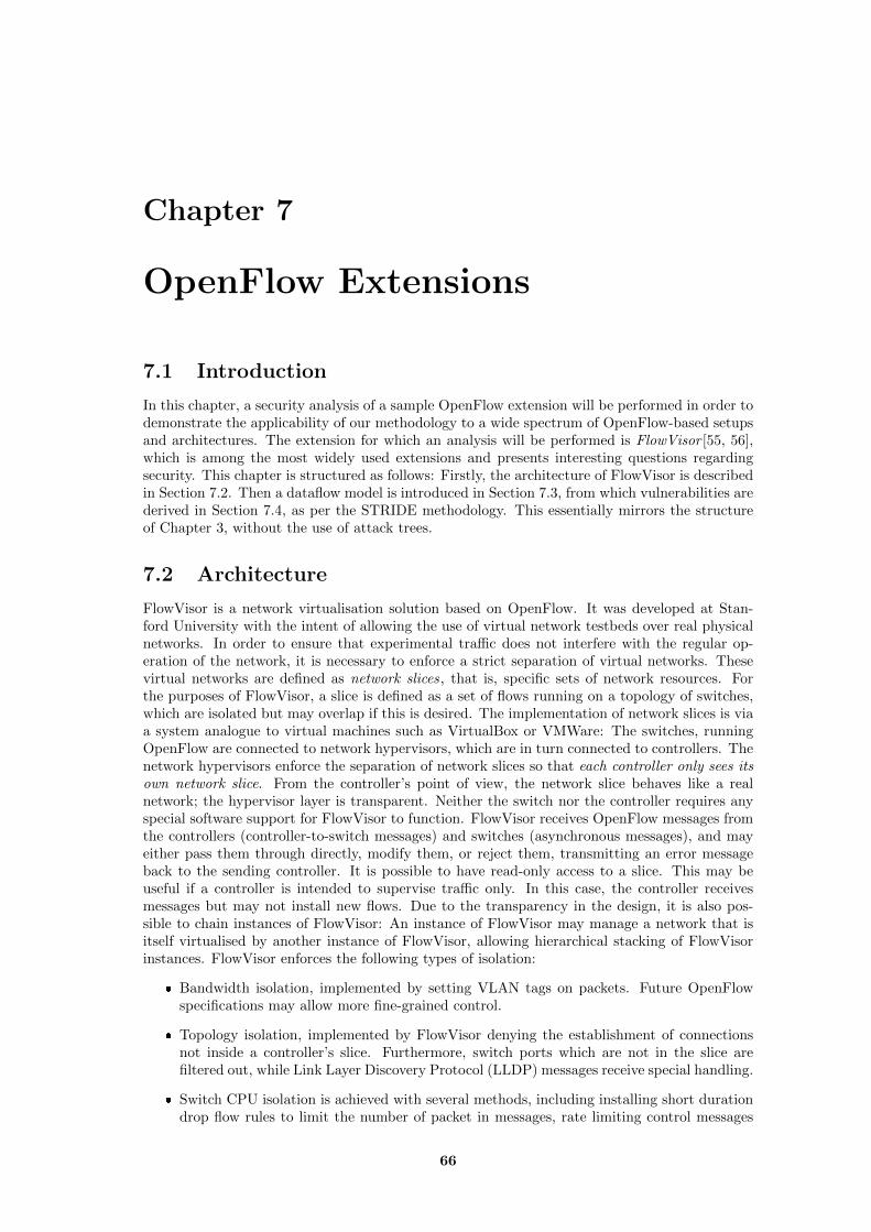
Chapter 7
OpenFlow Extensions
7.1 Introduction
In this chapter, a security analysis of a sample OpenFlow extension will be performed in order todemonstrate the applicability of our methodology to a wide spectrum of OpenFlow-based setupsand architectures. The extension for which an analysis will be performed is FlowVisor [55, 56],which is among the most widely used extensions and presents interesting questions regardingsecurity. This chapter is structured as follows: Firstly, the architecture of FlowVisor is describedin Section 7.2. Then a dataflow model is introduced in Section 7.3, from which vulnerabilities arederived in Section 7.4, as per the STRIDE methodology. This essentially mirrors the structureof Chapter 3, without the use of attack trees.
7.2 Architecture
FlowVisor is a network virtualisation solution based on OpenFlow. It was developed at Stan-ford University with the intent of allowing the use of virtual network testbeds over real physicalnetworks. In order to ensure that experimental traffic does not interfere with the regular op-eration of the network, it is necessary to enforce a strict separation of virtual networks. Thesevirtual networks are defined as network slices, that is, specific sets of network resources. Forthe purposes of FlowVisor, a slice is defined as a set of flows running on a topology of switches,which are isolated but may overlap if this is desired. The implementation of network slices is viaa system analogue to virtual machines such as VirtualBox or VMWare: The switches, runningOpenFlow are connected to network hypervisors, which are in turn connected to controllers. Thenetwork hypervisors enforce the separation of network slices so that each controller only sees itsown network slice. From the controller’s point of view, the network slice behaves like a realnetwork; the hypervisor layer is transparent. Neither the switch nor the controller requires anyspecial software support for FlowVisor to function. FlowVisor receives OpenFlow messages fromthe controllers (controller-to-switch messages) and switches (asynchronous messages), and mayeither pass them through directly, modify them, or reject them, transmitting an error messageback to the sending controller. It is possible to have read-only access to a slice. This may beuseful if a controller is intended to supervise traffic only. In this case, the controller receivesmessages but may not install new flows. Due to the transparency in the design, it is also pos-sible to chain instances of FlowVisor: An instance of FlowVisor may manage a network that isitself virtualised by another instance of FlowVisor, allowing hierarchical stacking of FlowVisorinstances. FlowVisor enforces the following types of isolation:
� Bandwidth isolation, implemented by setting VLAN tags on packets. Future OpenFlowspecifications may allow more fine-grained control.
� Topology isolation, implemented by FlowVisor denying the establishment of connectionsnot inside a controller’s slice. Furthermore, switch ports which are not in the slice arefiltered out, while Link Layer Discovery Protocol (LLDP) messages receive special handling.
� Switch CPU isolation is achieved with several methods, including installing short durationdrop flow rules to limit the number of packet in messages, rate limiting control messages
66
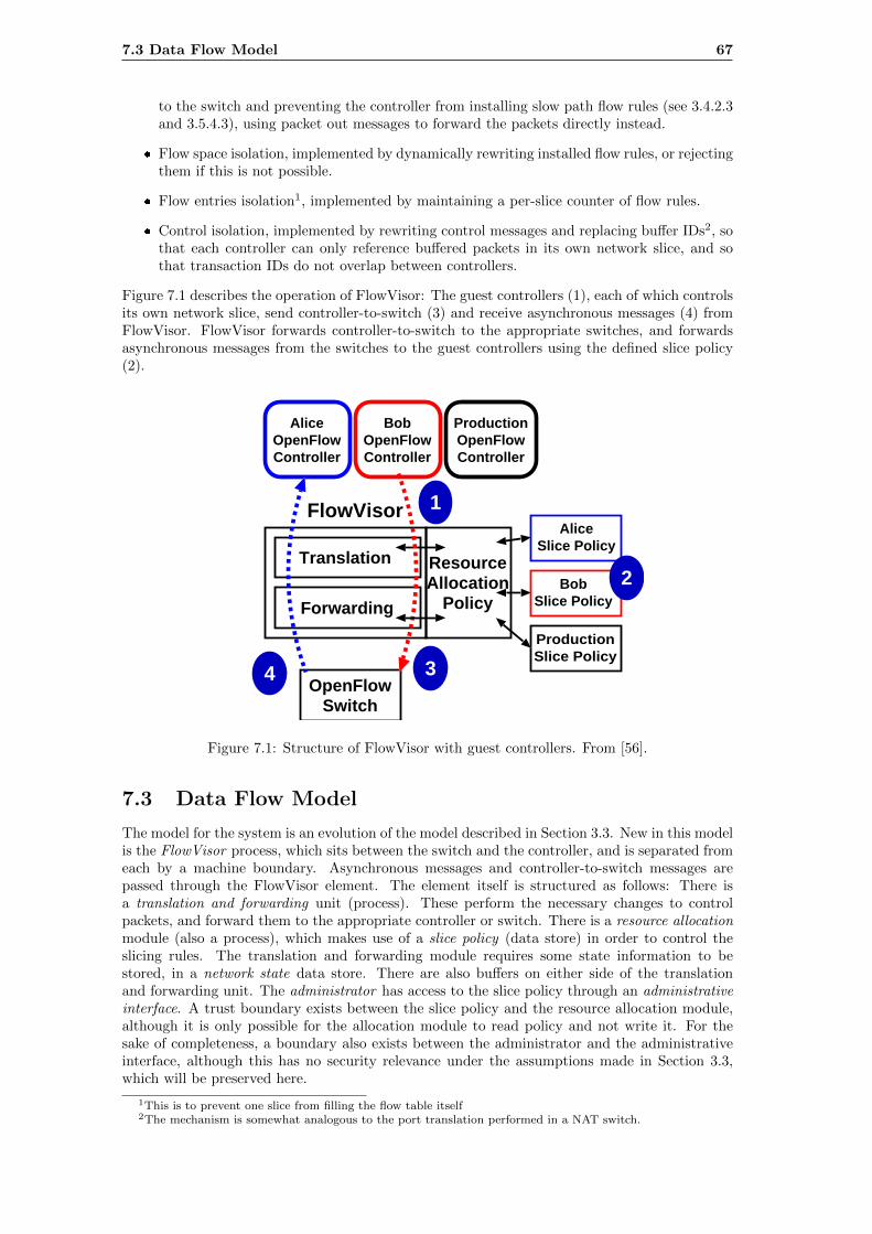
7.3 Data Flow Model 67
to the switch and preventing the controller from installing slow path flow rules (see 3.4.2.3and 3.5.4.3), using packet out messages to forward the packets directly instead.
� Flow space isolation, implemented by dynamically rewriting installed flow rules, or rejectingthem if this is not possible.
� Flow entries isolation1, implemented by maintaining a per-slice counter of flow rules.
� Control isolation, implemented by rewriting control messages and replacing buffer IDs2, sothat each controller can only reference buffered packets in its own network slice, and sothat transaction IDs do not overlap between controllers.
Figure 7.1 describes the operation of FlowVisor: The guest controllers (1), each of which controlsits own network slice, send controller-to-switch (3) and receive asynchronous messages (4) fromFlowVisor. FlowVisor forwards controller-to-switch to the appropriate switches, and forwardsasynchronous messages from the switches to the guest controllers using the defined slice policy(2).
ResourceAllocation
Policy
AliceSlice Policy
BobSlice Policy
ProductionSlice Policy
OpenFlowSwitch
AliceOpenFlowController
BobOpenFlowController
ProductionOpenFlowController
Forwarding
FlowVisor
Translation
3
2
1
4
Figure 2: The FlowVisor intercepts OpenFlow mes-sages from guest controllers (1) and, using the user’sslicing policy (2), transparently rewrites (3) the mes-sage to control only a slice of the network. Messagesfrom switches (4) are forwarded only to guests if itmatches their slice policy.
slice’s “flowspace”. In general, we say that FlowVisorslices traffic using flowspaces. Given a packet header(a single ”point”), FlowVisor can decide which flows-pace contains it, and therefore which slice (or slices) itbelongs to. FlowVisor can isolate two slices by mak-ing sure their flowspaces don’t overlap anywhere in thetopology; or it can decide which switches can be usedto communicate from one slice to another. It can alsoallow a packet to belong to two or more slices; for ex-ample, if one slice is used to monitor other slices.
3.2 FlowVisor Design GoalsFlowVisor was designed with the following goals: (1)
the virtualization should be transparent to the networkcontroller, (2) there should be strong isolation betweennetwork slices, and (3) the slice definition policy shouldbe rich and extensible. We discuss the rationale for eachof these choices below.
Transparency. The virtualization layer should betransparent to both the network hardware and the con-trollers managing the virtual networks. The reasons forthis are two-fold. First, an important motivation of vir-tual networks is the ability to prototype and debug pro-tocols on realistic topologies. If the controller must beactively aware of the virtualization layer, it is possible todesign a controller that functions in the virtual environ-ment but not the real network. Second, it’s important todecouple network virtualization technology from con-troller design so that they can be updated and improvedindependently. In our design, neither switch nor guest
OpenFlow controller need be modified to interoperatewith FlowVisor.
Isolation. The virtualization layer must enforcestrong isolation between slices—even under adversarialconditions. The promises of virtualization break downif one slice is able to exhaust the resources of another.We describe the details of the isolation mechanisms in§4 and evaluate their effectiveness in §5.
Extensible Slice Definition. Because we have lim-ited experience in operating virtual networks, it is im-portant to have a slicing policy that is flexible, extensi-ble, and modular. Much like an operating system sched-uler allocates CPU resources among many processes,the slicing policy must allocate networking resources(§2) among network slices. We believe resource alloca-tion among slices will be an active area of research. InFlowVisor, the slicing policy is implemented as a sepa-rate logical module for ease of development.
3.3 System DescriptionFlowVisor is a specialized OpenFlow controller.
FlowVisor acts as a transparent proxy betweenOpenFlow-enabled network devices and multiple guestOpenFlow controllers (Figure 2). All OpenFlow mes-sages, both from switch to guest and vice versa, are sentthrough FlowVisor. FlowVisor uses the OpenFlow pro-tocol to communicate with both guests and switches.The guest controllers require no modification and be-lieve they are communicating directly with the networkdevices.
We illustrate the FlowVisor’s operation with the fol-lowing simple example (Figure 2)—§6 describes morecompelling use-cases. Imagine an experimenter (Bob)builds a guest controller that is an HTTP load-balancerdesigned to spread all HTTP traffic over a set of servers.While the controller will work on any HTTP traffic,Bob’s FlowVisor policy slices the network so that heonly sees traffic from one particular IP source address.His guest controller doesn’t know the network has beensliced, so doesn’t realize it only sees a subset of theHTTP traffic. The guest controller thinks it can con-trol, i.e., insert flow entries for, all HTTP traffic fromany source address. When Bob’s controller sends a flowentry to the switches (e.g., to redirect HTTP traffic toa particular server), FlowVisor intercepts it (Figure 2-1), examines Bob’s slice policy (Figure 2-2), and re-writes the entry to include only traffic from the allowedsource (Figure 2-3). Hence the controller is controllingonly the flows it is allowed to, without knowing thatthe FlowVisor is slicing the network underneath. Sim-ilarly, messages that are sourced from the switch (e.g.,a new flow event—Figure 2-4) are only forwarded toguest controllers whose flowspace match the message.
Thus, FlowVisor enforces transparency and isolation
4
Figure 7.1: Structure of FlowVisor with guest controllers. From [56].
7.3 Data Flow Model
The model for the system is an evolution of the model described in Section 3.3. New in this modelis the FlowVisor process, which sits between the switch and the controller, and is separated fromeach by a machine boundary. Asynchronous messages and controller-to-switch messages arepassed through the FlowVisor element. The element itself is structured as follows: There isa translation and forwarding unit (process). These perform the necessary changes to controlpackets, and forward them to the appropriate controller or switch. There is a resource allocationmodule (also a process), which makes use of a slice policy (data store) in order to control theslicing rules. The translation and forwarding module requires some state information to bestored, in a network state data store. There are also buffers on either side of the translationand forwarding unit. The administrator has access to the slice policy through an administrativeinterface. A trust boundary exists between the slice policy and the resource allocation module,although it is only possible for the allocation module to read policy and not write it. For thesake of completeness, a boundary also exists between the administrator and the administrativeinterface, although this has no security relevance under the assumptions made in Section 3.3,which will be preserved here.
1This is to prevent one slice from filling the flow table itself2The mechanism is somewhat analogous to the port translation performed in a NAT switch.
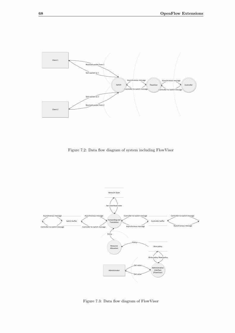
68 OpenFlow Extensions
Client 1
Switch
Received packet from 1
Sent packet to 1
Sent packet to 2
Received packet from 2
Client 2
ControllerFlowVisor
Asynchronous message
Controller-to-switch message
Asynchronous message
Controller-to-switch message
Figure 7.2: Data flow diagram of system including FlowVisor
Asynchronous message
Controller-to-switch messageAsynchronous message
Controller-to-switch message
Forwarding and Translation
Network State
Set state Read state
Switch buffer Controller buffer
Asynchronous message
Controller-to-switch message
Controller-to-switch message
Asynchronous message
Resource Allocation
Policy
Slice policy
Policy
Administrative Interface
(FlowVisor)
Write policy
Administrator
Set value
Read policy
Get value
Figure 7.3: Data flow diagram of FlowVisor
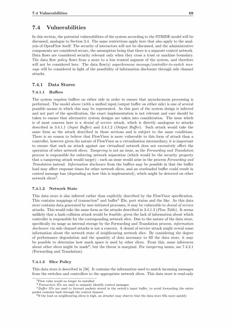
7.4 Vulnerabilities 69
7.4 Vulnerabilities
In this section, the potential vulnerabilities of the system according to the STRIDE model will bediscussed, analogue to Section 3.4. The same restrictions apply here that also apply to the anal-ysis of OpenFlow itself: The security of interactors will not be discussed, and the administrativecomponents are considered secure, the assumption being that there is a separate control network.Data flows are considered security relevant only when they cross a trust or machine boundary.The data flow policy flows from a more to a less trusted segment of the system, and thereforewill not be considered here. The data flow(s) asynchronous message/controller-to-switch mes-sage will be considered in light of the possibility of information disclosure through side channelattacks.
7.4.1 Data Stores
7.4.1.1 Buffers
The system requires buffers on either side in order to ensure that asynchronous processing isperformed. The model above (with a unified input/output buffer on either side) is one of severalpossible means in which this may be represented. As this part of the system design is inferredand not part of the specification, the exact implementation is not relevant and care should betaken to ensure that alternative system designs are taken into consideration. The issue whichis of most concern here is a denial of service attack, which is directly analogous to attacksdescribed in 3.4.1.1 (Input Buffer) and 3.4.1.2 (Output Buffer). Such attack would take thesame form as the attack described in those sections and is subject to the same conditions.There is no reason to believe that FlowVisor is more vulnerable to this form of attack than acontroller, however given the nature of FlowVisor as a virtualisation intermediary, it is importantto ensure that such an attack against one virtualised network does not excessively effect theoperation of other network slices. Tampering is not an issue, as the Forwarding and Translationprocess is responsible for enforcing network separation (which would be the security propertythat a tampering attack would target) - such an issue would arise in the process Forwarding andTranslation instead. Information disclosure from the buffers may be possible in that the bufferload may affect response times for other network slices, and an overloaded buffer could result incontrol message loss (depending on how this is implemented), which might be detected on othernetwork slices3.
7.4.1.2 Network State
This data store is also inferred rather than explicitly described by the FlowVisor specification.This contains mappings of transaction4 and buffer5 IDs, port status and the like. As this datastore contains data generated by user-initiated processes, it may be vulnerable to denial of serviceattacks. This would take the same form as the attacks described in 3.4.1.3 (Flow Table). It seemsunlikely that a hash collision attack would be feasible, given the lack of information about whichcontroller is responsible for the corresponding network slice. Due to the nature of the data store,specifically its usage as internal storage by the Forwarding and Translation process, informationdisclosure via side channel attacks is not a concern. A denial of service attack might reveal someinformation about the network state of neighbouring network slice. By considering the degreeof performance degradation and the quantity of data necessary to fill the data store, it maybe possible to determine how much space is used by other slices. From this, some inferencesabout other slices might be made6, but the threat is marginal. For tampering issues, see 7.4.2.1(Forwarding and Translation).
7.4.1.3 Slice Policy
This data store is described in [56]. It contains the information used to match incoming messagesfrom the switches and controllers to the appropriate network slices. This data store is read-only
3Flow rules would no longer be installed4Transaction IDs are used to uniquely identify control messages5Buffer IDs are used to forward packets stored in the switch’s input buffer, to avoid forwarding the entire
packet contents back through the control channel6If the load on neighbouring slices is high, an attacker may observe that the data store fills more quickly
70 OpenFlow Extensions
from the perspective of the external network; it may only be modified by the administrator. It istherefore not vulnerable to either tampering or denial of service. Information disclosure may beaccomplished indirectly via the data flow Asynchronous Message/Controller-to-switch Message.
7.4.2 Processes
7.4.2.1 Forwarding and Translation
This process has two functions, as the name suggests: Firstly, received messages, allocated to aparticular network slice, are translated in such a way that the function of FlowVisor is transparentto both the switches and the controllers. Secondly, the packets are forwarded onto the switchor controller to which the slice belongs. Denial of service attacks may have the objective ofoverwhelming the forwarding/translation process, of filling available memory (see 7.4.1.1 and7.4.1.2), or of exploiting any security holes in the process itself. It is essential that isolation isensured, therefore a denial of service attack on one network slice should have no effect on any otherslice. Based on the design outlined in [56], it is not clear how this can be guaranteed. Tamperingshould be taken into consideration by the administrator. It must be ensured that it is not possibleto inject packets into another network slice, though it is assumed that a reasonable allocationpolicy will prevent this from occurring in practice. With respect to information disclosure, apotential issue is that the performance of one network slice may impact the performance of othernetwork slices in a way that is detectable and measurable; this may be used to learn about othernetwork slices, violating the isolation. In particular, it may be possible to learn the network loadon another slice by measuring throughput and response times.In addition to this, the operation of the virtualisation itself may cause some issues. For instance,flow rules which are executed on the switch’s processor are generally not installed on the switchitself, but rather handled by FlowVisor directly7, which is far more time consuming. If a userwere to notice this, he or she may infer that network virtualisation is in use. Moreover, theextra network traffic may present a possibility for a denial of service attack. The enforcementof bandwidth and CPU time limits by FlowVisor is also rather rudimentary; this is due tolimitations in the OpenFlow protocol rather than shortcomings of the FlowVisor design and it islikely that isolation will be improved when newer versions of the OpenFlow protocol enter intowidespread use.
7.4.2.2 Resource Allocation
This process represents the modular component responsible for resource allocation: It defineshow packets are mapped to network slices. In particular, its modular nature allows other criteriato be used for partitioning the network into slices than those supported by default. As it stands,the slicing policy is not itself vulnerable to attack, for the same reasons as discussed in 7.4.1.3(Slice Policy). A more complicated module might open avenues of attack: If, for instance, theassignment of network traffic to slices was performed dynamically rather than statically, theattack surface would increase significantly. These may include denial of service attacks targetingthe internal state or processing, information disclosure attacks seeking to discover the slicingpolicy by examining reactions to attacker-generated traffic, or tampering attacks attempting toinfluence the slicing policy. The exact form of these attacks would depend on the implementationof the module, however possible attacks must be taken into account if a new module is to beimplemented.
7.4.3 Data Flows
7.4.3.1 Asynchronous Message/Controller-to-switch Message
This represents several data flows through the “data path” of FlowVisor8. Due to the time delayintroduced by the presence of FlowVisor, the possibility of information disclosure due to a timinganalysis attack is introduced. This is analogous to the attack described in 3.4.3.3 (AsynchronousMessage). Due to the presence of multiple network hops, more information can be obtainedhere than in the case of an ordinary OpenFlow network. If the timing properties of different
7“FlowVisor prevents guest controllers from inserting slow-path forwarding rules by rewriting them as one-timepacket forwarding events, i.e., an OpenFlow “packet out” message.” from p.7 of [56]
8Which is actually the control path of the OpenFlow network.
7.5 Conclusion 71
OpenFlow controllers is different, and this difference is distinguishable, it may even be possibleto detect which controller is attached to which network slice.
7.5 Conclusion
FlowVisor promises to allow the operation of virtual network slices over production networks.With this in mind, it is important to consider the consequences of its operation. The extracomplexity and overhead of FlowVisor increases attack surface area, as compared to an ordinaryOpenFlow network. The FlowVisor system is a single point of failure in case of a denial ofservice attack, which could also prevent the operation of the production network. Given timingdifferences between a FlowVisor network and an ordinary OpenFlow network, the slicing maybe noticeable and certain aspects of its operation observable. An attacker may even be able todetermine which controller is managing a particular network slice, allowing him or her to makeinferences about slicing policy. The slicing policy itself must be checked carefully to ensure thatit is self-consistent; a form of validation may be useful here. It is not clear that all of the isolationproperties proposed in [56] can be enforced in practice. Some may even aggravate security issues,by increasing the network traffic load, making it more vulnerable to denial of service attacks.The exploitation of the denial of service and information disclosure issues here take similar formsto those considered in Section 3.5, so no separate attack trees are provided for these issues. Someissues here may be alleviated by applying newer versions of OpenFlow - this applies mostly to theenforcement of isolation properties. The introduction of bandwidth metering in 1.3.0 (Section4.5) greatly increases the efficacy of this form of isolation. It also provides an avenue to protectfrom denial of service attacks. In general, FlowVisor constitutes an interesting tool, but it shouldbe used with care on production networks with untrusted users.
Chapter 8
Future Work
8.1 Introduction
As stated in Section 1.2, OpenFlow is no longer merely of academic interest, as it is increasinglybeing deployed in real-world systems[26]. It has often been the case that technical standardshave been focused on functionality at the expense of security. In the future, security should beconsidered from the very first draft, not added on shortly before release or offered as an extension.
8.2 Security Modelling
This thesis makes use of two different methodologies - described in 2.2.1 (Uncover Security DesignFlaws Using The STRIDE Approach) and 2.3.1 (Threat Modelling Using Attack Trees) - to modeland analyse the OpenFlow protocol. The STRIDE methodology is dataflow-oriented and doesnot take into account other aspects of security, such as timing. Attack trees require that potentialattacks already be known. Numerous other methods described in Section 2.4 may be attempted,although the protocol as described in the standards unfortunately can not be readily modelledusing state based models such as Petri nets. Even so, for the sake of validity it would be usefulto compare the chosen methodologies with other existing methodologies.It would also be desirable to apply the STRIDE method to newer OpenFlow standards. Thismight have been attempted in this paper, however the newer standards have seen few implemen-tations so far, making the 1.0 standard by far the most relevant in practice. Chapter 4 gives abrief overview of the potentially security-relevant changes introduced in the subsequent Open-Flow standards. These changes have not been modelled or analysed using a formal methodologyof any kind; this or the modelling of other OpenFlow extensions could be the subject of a futurework, if these see widespread adoption.
8.3 Empirical Testing
This thesis makes use of Mininet 2.0 as a test environment for experimentation with OpenFlow.Although the primary intent of Chapter 5 is to attempt to exploit issues described in Chapter 3,it could also be used to model a wide range of other scenarios, as OpenFlow-managed networkscan encounter scalability and performance issues in the absence of any malicious traffic. Themitigations proposed in Chapter 6 have yet to be tested, especially on production systems.It would be particularly desirable to have a test suite that could be used to validate switchand/or controller design, as a form of general stress test or as a specific unit test for particularvulnerabilities; the software developed for Chapter 5 could be a basis for this. Testing switchand controller design has also been the topic of other works, such as [11]. The use of physicalhardware would allow the impact of such attacks on real-world systems to be determined; thereare significant differences in the behaviour of a simulated network environment with little orno concurrent traffic and a real network environment with substantial non-malicious traffic andother performance constraints. Furthermore, the increasing use of virtual networks in cloudsystems makes testing attack scenarios on such systems vital - it is known that virtualisationenvironments allow for novel attack types[4].
72
Chapter 9
Summary
This thesis consists of a security analysis of OpenFlow, an experimental examination of some theissues uncovered in the analysis and a discussion of strategies to prevent and mitigate securityissues found. Here, some of the most important results will be summarised.The analysis was based on the STRIDE methodology (described in 2.2.1). Based on an analysisof the OpenFlow Switch Specification 1.0, a data flow model was developed, describing theinteraction of the switch and the controller. The application of the STRIDE methodology resultsin an enumeration of vulnerabilities. These include denial of service, information disclosureand tampering attacks. The denial of service vulnerabilities arise from the flow table, the controlchannel between the switch and the controller, and the controller. An attacker generating a largenumber of flows can overload these components, resulting in the network no longer operatingcorrectly. The information disclosure issues arise from the time delay caused by packets beingtransmitted over the control channel, as well as delays caused by the fast and slow path of theswitch. All of these represent timing analysis attacks - a form of side channel attack. Tamperingissues arise from the installation of flow rules based on packets originating from an untrusted hostby a controller. Such packets may include LLDP packets with forged source addresses, leadingthe controller to install flow rules based on false information. The issue is therefore similar tocache poisoning attacks, such as ARP or DNS cache poisoning attacks. A number of other issuesare also discussed, from the possibility of counters overflowing, and the consequences this mighthave, to the possibility of mounting a hash collision attack against various data stores which areimplemented as a hash table. Subsequently, there is a discussion of the impact of newer versionsof the OpenFlow specification, which both allow some of the security problems of OpenFlow tobe mitigated, but also increase its complexity and therefore its attack surface.The experimental examination performs a demonstration of the denial of service and informationdisclosure vulnerabilities. Based on setup using the Mininet network simulator and the POXcontroller framework, the effects of a denial of service attack are simulated with varying timeoutvalues, as well as different performance constraints. A different controller also emulates theeffect of aggregation (covering more than one network flow with the same flow rule). The resultsdemonstrate that shorter timeout values as well as greater aggregation decrease the effect ofdenial of service on network performance. The effects of a denial of service attack are also shownto be dependent on the performance of the link between the controller and the switch, as wasto be expected. The information disclosure issue is evaluated with simulated server and severalclients. By using a simple aggregating controller - it merely applies wildcards to source addressand port values - it is possible to demonstrate that the attacking host can determine whether ornot a connection is active between a third party and the server. It is also shown that the latencyof the control link has an effect on the ease with which such an inference can be made.Finally, there is a discussion about prevention and mitigation techniques for the issues describedabove. Different network types as well as different applications of OpenFlow and their require-ments are reviewed. For denial of service, information disclosure and tampering attacks, severalapproaches are introduced and their domain of application, advantages and disadvantages dis-cussed.
73
Nomenclature
actions . . . . . . . . . . . . . . . . . . . . . . . . The fields of the flow table entry which are used to define theactions the switch should take on packets which match the flowrule
aggregation . . . . . . . . . . . . . . . . . . . . The creation of flow rules using wildcards and/or network pre-fixes so that they encompass multiple network flows
anomaly detection . . . . . . . . . . . . . A method for detecting unusual or anomalous aspects of net-work flows, in order to detect attacks, misconfiguration, linkfailure or other issues
asymmetric . . . . . . . . . . . . . . . . . . . . Type of communication between the switch and controller. In-volves messages that are sent by the switch to the controllerwithout its solicitation and without a reply being waited for,for instance to notify the controller of a new flow
attack trees . . . . . . . . . . . . . . . . . . . A schematic representation of potential methods of attackinga system, based on fault analysis trees
authentication . . . . . . . . . . . . . . . . . Security measure to verify that a user or system identitymatches the claimed identity. Protects against spoofing
authorization . . . . . . . . . . . . . . . . . . Security measure to ensure that an authorised user or systemis only able to perform actions or access data that it is entitledto, according to policy. Protects against elevation of privilege
availability . . . . . . . . . . . . . . . . . . . . Security measure to ensure that a process or system remainsavailable to authorised systems or users, even in the face ofmalicious interference. Protects against denial of service
confidentiality . . . . . . . . . . . . . . . . . Security measure to prevent a user or system from accessingdata without prior authentication and authorisation. Protectsagainst information disclosure
control plane . . . . . . . . . . . . . . . . . . The part of a switch designed to handle the updating of theforwarding table, as well as other operations that do not occurat line rate. In an OpenFlow system, these operations areperformed on an external controller
controller-to-switch . . . . . . . . . . . . Type of communication between the switch and controller. In-volves messages that are sent by the controller to the switchwithout its solicitation, such as that used to install a new flowrule
counters . . . . . . . . . . . . . . . . . . . . . . . The fields of the flow table entry which are used to keep trackof per-flow statistics
data flows . . . . . . . . . . . . . . . . . . . . . In a data flow diagram, the element that models a flow of databetween two other elements, such as a network connection.Also includes pure internal flows.
data plane . . . . . . . . . . . . . . . . . . . . . The part of a switch designed to handle the forwarding of pack-ets, as well as other supported operations (such as stripping aVLAN tag), at line rates
data stores . . . . . . . . . . . . . . . . . . . . In a data flow diagram, the element that models a store ofdata, such as a file or database
dataflow diagram . . . . . . . . . . . . . . A schematic description of the flows of data inside a system.Contains elements of data stores, data flows, processes andinteractors
demilitarised zone . . . . . . . . . . . . . In a network protected by firewalls and/or intrustion preven-
74
Nomenclature 75
tion systems, the part of the network which is accessible to ex-ternal systems, typically containing servers providing servicesto third parties (web, email, DNS and so forth)
denial of service . . . . . . . . . . . . . . . Attack type that involves malicious disruption of the operationof a system or process. For instance, a TCP SYN flood or resetattack
differentiated services . . . . . . . . . . A form of quality of service enforcement where traffic is clas-sified by a tag, and traffic with different levels of priority isforwarded in different queues. Depending on the classification,guarantees of performance may be provided. Low priority traf-fic may be dropped preferentially
drop . . . . . . . . . . . . . . . . . . . . . . . . . . . Supported action on the switch. Results in packet being aban-doned
elevation of privilege . . . . . . . . . . . Attack type that acquiring permissions to perform actionsand/or access data that a user or process by design is notentitled to. For instance, a stack buffer overflow
enqueue . . . . . . . . . . . . . . . . . . . . . . . Supported action on the switch. Same parameters as the for-ward action, but uses per-port queueing to enforce quality ofservice
flow . . . . . . . . . . . . . . . . . . . . . . . . . . . A network flow is a tuple containing the transport layer pro-tocol, the source and destination addresses and the source anddestination ports
flow rule . . . . . . . . . . . . . . . . . . . . . . . An entry in the flow table, describing the desired reaction toreceived packets matching specified headers. Installed by thecontroller.
flow table . . . . . . . . . . . . . . . . . . . . . Data store on the switch that consists of a list of flow rulesinstalled by the controller. Each rule consists of header fieldsthat must be matched (possibly with wildcards), actions to betaken on match as well as counters for statistical purposes
forward . . . . . . . . . . . . . . . . . . . . . . . Supported action on the switch. Results in packet being for-warded to a physical or virtual port
header fields . . . . . . . . . . . . . . . . . . . The fields of the flow table entry which are used for matchingthe header fields of the packet
information disclosure . . . . . . . . . Attack type that involves acquiring information that by designa user or process should not have access to
integrity . . . . . . . . . . . . . . . . . . . . . . . Security measure to verify that data has not been maliciouslymodified. Protects against tampering
interactors . . . . . . . . . . . . . . . . . . . . . In a data flow diagram, the element which represents exter-nal systems (including people) that interact with the systemcomponents
LLDP . . . . . . . . . . . . . . . . . . . . . . . . . Short for Link Layer Discovery Protocol. Protocol which sup-ports the discovery of network topology and of the capabilitiesof devices connected to the network
management network . . . . . . . . . . The network that is used to connect the controller to switchesunder its control
Mininet . . . . . . . . . . . . . . . . . . . . . . . A network virtualisation testbed which can simulate arbitrarynetwork topologies as well as a variety of performance con-straints. Based on Linux network namespaces and imple-mented with OpenFlow, it has a Python-based API and canalso be used from the command line in simple cases.
modify field . . . . . . . . . . . . . . . . . . . Supported action on the switch. Allows a field of the packetheader to be modified as specified in the flow table
NDP . . . . . . . . . . . . . . . . . . . . . . . . . . Short for neighbourhood discovery protocol, this provide ser-vices for IPv6 networks similar to, but more extensive than,the services that ARP provides for IPv4 networks
netcat . . . . . . . . . . . . . . . . . . . . . . . . . Networking tool which allows data to be piped over TCP andUDP sockets to another client running netcat
network neutrality . . . . . . . . . . . . . The proposed principle that all types of traffic in a network
76 Nomenclature
should be treated equally, generally precluding the use of trafficshaping and quality of service measures
network slices . . . . . . . . . . . . . . . . . A virtual network that is implemented by a network hypervisor,such as that implemented in FlowVisor. The slice is similar to aVLAN, but with fewer constraints in its structure. Individualnetwork slices are strictly separated from each other, just asvirtual machines running on a physical machines are.
non-repudiation . . . . . . . . . . . . . . . Security measure to prevent a user or system from crediblydenying an action that it has performed, or its authorship ofdata. Protects against repudiation
POX . . . . . . . . . . . . . . . . . . . . . . . . . . A Python-based, modular controller framework. Can supporta variety of strategies
proactive strategy . . . . . . . . . . . . . A strategy where the controller anticipates new flows and in-stalls new flow rules before they are instantiated. The flowrules may also aggregate several flows into a single flow ruleusing wildcards
processes . . . . . . . . . . . . . . . . . . . . . . In a data flow diagram, the element that represents processes,either actual programmatic processes, or abstract processes -which may be broken down into subprocesses
reactive strategy . . . . . . . . . . . . . . . A strategy where the controller installs flow rules in responseto received packets instantiating new flows
repudiation . . . . . . . . . . . . . . . . . . . . Attack type that involves denying the origin of data or actionsrole based access control . . . . . . . A system of access control where access policy is determined
by a user’s assigned roles in a system (a user can have anynumber of different roles)
scapy . . . . . . . . . . . . . . . . . . . . . . . . . . A Python-based packet generation framework that can be usedto simulate, or actually perform, a variety of network-basedattacks.
service-level agreement . . . . . . . . A contract defining the minimum level of performance and reli-ability that must be provided (downtime, throughput, latency,response time etc.)
side channel attack . . . . . . . . . . . . A class of attacks that result in information disclosure throughthe external measurement of observable quantities which arecorrelated with internal system properties, where the systemdesign would not allow the properties to be revealed. Examplesinclude timing analysis, power analysis and acoustic analysis
software defined networking . . . A networking paradigm where the control plane of a networkis separated from the data plane.
spoofing . . . . . . . . . . . . . . . . . . . . . . . Attack type that involves emulating another identity. For in-stance, IP address spoofing
STRIDE . . . . . . . . . . . . . . . . . . . . . . Abbreviation for Spoofing, Tampering, Repudiation, Informa-tion disclosure, Denial of Service, Elevation of privilege. Ap-proach to analysing the security of a system design
symmetric . . . . . . . . . . . . . . . . . . . . . Type of communication between the switch and controller. In-volves messages sent from either controller or switch to theother and for which a response is expected, for instance mes-sages generated to ensure connection liveness
tampering . . . . . . . . . . . . . . . . . . . . . Attack type that involves malicious manipulation of data. ATCP connection hijacking attack is one example of this
timing analysis . . . . . . . . . . . . . . . . A type of side channel attack that results on information dis-closure due to the internal (confidential or not otherwise avail-able) state of a system having a predictable and statisticallysignificant effect on measurable response times
traffic analysis . . . . . . . . . . . . . . . . . A form of attack which makes use of transmission metadatarather than the contents of (encrypted) transmission
trust boundaries . . . . . . . . . . . . . . . In a data flow diagram, an element which separates elementsat different level of trust, for instance between privileged andunprivileged operations
References
[1] Marwan Abi-Antoun, Daniel Wang, and Peter Torr. Checking threat modeling data flowdiagrams for implementation conformance and security. In Proceedings of the twenty-secondIEEE/ACM international conference on Automated software engineering, ASE ’07, pages393–396, New York, NY, USA, 2007. ACM.
[2] S. Al-Fedaghi and A.A. Alrashed. Threat Risk Modeling. In Communication Software andNetworks, 2010. ICCSN ’10. Second International Conference on, pages 405–411, feb. 2010.
[3] Amenaza Technologies. SecurITree. http://www.amenaza.com/SS-what_is.php.Accessed on 02.04.2013.
[4] Amittai Aviram, Sen Hu, Bryan Ford, and Ramakrishna Gummadi. Determinating timingchannels in compute clouds. In Proceedings of the 2010 ACM workshop on Cloud computingsecurity workshop, CCSW ’10, pages 103–108, New York, NY, USA, 2010. ACM.
[5] David Basin, Manuel Clavel, and Marina Egea. A decade of model-driven security. In Pro-ceedings of the 16th ACM symposium on Access control models and technologies, SACMAT’11, pages 1–10, New York, NY, USA, 2011. ACM.
[6] David Basin, Jurgen Doser, and Torsten Lodderstedt. Model driven security for process-oriented systems. In Proceedings of the eighth ACM symposium on Access control modelsand technologies, SACMAT ’03, pages 100–109, New York, NY, USA, 2003. ACM.
[7] David Basin, Jurgen Doser, and Torsten Lodderstedt. Model driven security: From UMLmodels to access control infrastructures. ACM Trans. Softw. Eng. Methodol., 15(1):39–91,January 2006.
[8] Udi Ben-Porat, Anat Bremler-Barr, Hanoch Levy, and Bernhard Plattner. On the vulner-ability of hardware hash tables to sophisticated attacks. In Proceedings of the 11th inter-national IFIP TC 6 conference on Networking - Volume Part I, IFIP’12, pages 135–148,Berlin, Heidelberg, 2012. Springer-Verlag.
[9] Philippe Biondi. Scapy. http://www.secdev.org/projects/scapy/. Accessed on02.04.2013.
[10] R. Braga, E. Mota, and A. Passito. Lightweight DDoS flooding attack detection usingNOX/OpenFlow. In Local Computer Networks (LCN), 2010 IEEE 35th Conference on,pages 408–415, oct. 2010.
[11] Marco Canini, Daniele Venzano, Peter Peresıni, Dejan Kostic, and Jennifer Rexford. ANICE way to test openflow applications. In Proceedings of the 9th USENIX conference onNetworked Systems Design and Implementation, NSDI’12, pages 10–10, Berkeley, CA, USA,2012. USENIX Association.
[12] Jieren Cheng, Jianping Yin, Chengkun Wu, Boyun Zhang, and Yun Liu. DDoS attackdetection method based on linear prediction model. In Proceedings of the 5th internationalconference on Emerging intelligent computing technology and applications, ICIC’09, pages1004–1013, Berlin, Heidelberg, 2009. Springer-Verlag.
[13] Cisco Systems. Virtual LAN Security Best Practices. http://www.cisco.com/warp/public/cc/pd/si/casi/ca6000/prodlit/vlnwp_wp.pdf. Accessed on 02.04.2013.
77
78 REFERENCES
[14] K. Daley, R. Larson, and J. Dawkins. A structural framework for modeling multi-stagenetwork attacks. In Parallel Processing Workshops, 2002. Proceedings. International Con-ference on, pages 5–10, 2002.
[15] B. S. Davie, A. Charny, J. W. R., K. Blair Benson, J. Y. Le, W. Courtney, S. Davari,and V. Firoiu. An expedited forwarding PHB (Per-Hop behavior). RFC 3246, InternetEngineering Task Force, March 2002.
[16] P. Dely, A. Kassler, and N. Bayer. OpenFlow for Wireless Mesh Networks. In ComputerCommunications and Networks (ICCCN), 2011 Proceedings of 20th International Confer-ence on, pages 1–6, 31 2011-aug. 4 2011.
[17] M. Desai and T. Nandagopal. Coping with link failures in centralized control plane architec-tures. In Communication Systems and Networks (COMSNETS), 2010 Second InternationalConference on, pages 1–10, jan. 2010.
[18] Martin Devera. HTB - Hierarchy Token Bucket. http://lartc.org/manpages/tc-htb.html. Accessed on 02.04.2013.
[19] O. El Ariss, Jianfei Wu, and Dianxiang Xu. Towards an Enhanced Design Level Security:Integrating Attack Trees with Statecharts. In Secure Software Integration and ReliabilityImprovement (SSIRI), 2011 Fifth International Conference on, pages 1–10, june 2011.
[20] Omar El Ariss and Dianxiang Xu. Modeling security attacks with statecharts. In Proceedingsof the joint ACM SIGSOFT conference – QoSA and ACM SIGSOFT symposium – ISARCSon Quality of software architectures – QoSA and architecting critical systems – ISARCS,QoSA-ISARCS ’11, pages 123–132, New York, NY, USA, 2011. ACM.
[21] Giovanni Giacobbi. The GNU Netcat project. http://netcat.sourceforge.net/.Accessed on 02.04.2013.
[22] D. Grossman. New terminology and clarifications for diffserv. RFC 3260, Internet Engi-neering Task Force, April 2002.
[23] Nikhil Handigol, Brandon Heller, Vimalkumar Jeyakumar, Bob Lantz, and Nick McKe-own. Reproducible network experiments using container-based emulation. In Proceedingsof the 8th international conference on Emerging networking experiments and technologies,CoNEXT ’12, pages 253–264, New York, NY, USA, 2012. ACM.
[24] J. Heinanen, F. Baker, W. Weiss, and J. Wroclawski. Assured forwarding PHB group. RFC2597, Internet Engineering Task Force, June 1999.
[25] Shawn Hernan, Scott Lambert, Tomasz Ostwald, and Adam Shostack. Uncover SecurityDesign Flaws Using The STRIDE Approach, 2006.
[26] Urs Hoelzle. OpenFlow @ Google. http://opennetsummit.org/archives/apr12/hoelzle-tue-openflow.pdf. Accessed on 02.04.2013.
[27] HP Networking. OpenFlow. http://h17007.www1.hp.com/us/en/mobile/solutions/enterprise/openflow.html. Accessed on 02.04.2013.
[28] Jafar Haadi Jafarian, Ehab Al-Shaer, and Qi Duan. Openflow random host mutation:transparent moving target defense using software defined networking. In Proceedings of thefirst workshop on Hot topics in software defined networks, HotSDN ’12, pages 127–132, NewYork, NY, USA, 2012. ACM.
[29] Juniper Networks. OpenFlow Switch Application (OF-APP) for Juniper MX-Series Routers. https://developer.juniper.net/shared/jdn/docs/ProgrammableNetworks/OpenFLow_APP_JDN_Overview.pdf. Accessed on02.04.2013.
[30] P.A. Khand. System level security modeling using attack trees. In Computer, Control andCommunication, 2009. IC4 2009. 2nd International Conference on, pages 1–6, feb. 2009.
REFERENCES 79
[31] Ahmed Khurshid, Wenxuan Zhou, Matthew Caesar, and P. Brighten Godfrey. VeriFlow:verifying network-wide invariants in real time. In Proceedings of the first workshop on Hottopics in software defined networks, HotSDN ’12, pages 49–54, New York, NY, USA, 2012.ACM.
[32] Seong Soo Kim and A. L. Narasimha Reddy. Statistical techniques for detecting trafficanomalies through packet header data. IEEE/ACM Trans. Netw., 16(3):562–575, June2008.
[33] Boris Koldehofe, Frank Durr, Muhammad Adnan Tariq, and Kurt Rothermel. The power ofsoftware-defined networking: line-rate content-based routing using OpenFlow. In Proceed-ings of the 7th Workshop on Middleware for Next Generation Internet Computing, MW4NG’12, pages 3:1–3:6, New York, NY, USA, 2012. ACM.
[34] lxc Linux Containers. http://lxc.sourceforge.net/index.php/about/kernel-namespaces/network/. Accessed on 02.04.2013.
[35] Arif Mahmud, Rahim Rahmani, and Theo Kanter. Deployment of Flow-Sensors in Internetof Things’ Virtualization via OpenFlow. In Mobile, Ubiquitous, and Intelligent Computing(MUSIC), 2012 Third FTRA International Conference on, pages 195–200, june 2012.
[36] Syed Akbar Mehdi, Junaid Khalid, and Syed Ali Khayam. Revisiting traffic anomaly detec-tion using software defined networking. In Proceedings of the 14th international conferenceon Recent Advances in Intrusion Detection, RAID’11, pages 161–180, Berlin, Heidelberg,2011. Springer-Verlag.
[37] Paul Menage. Control Groups. http://www.kernel.org/doc/Documentation/cgroups/cgroups.txt. Accessed on 02.04.2013.
[38] Mininet. http://mininet.github.com/. Accessed on 02.04.2013.
[39] A. Morais, E. Martins, A. Cavalli, and W. Jimenez. Security Protocol Testing Using AttackTrees. In Computational Science and Engineering, 2009. CSE ’09. International Conferenceon, volume 2, pages 690–697, aug. 2009.
[40] Yukihiro Nakagawa, Kazuki Hyoudou, and Takeshi Shimizu. A management method of IPmulticast in overlay networks using openflow. In Proceedings of the first workshop on Hottopics in software defined networks, HotSDN ’12, pages 91–96, New York, NY, USA, 2012.ACM.
[41] Jad Naous, David Erickson, G. Adam Covington, Guido Appenzeller, and Nick McKeown.Implementing an OpenFlow switch on the NetFPGA platform. In Proceedings of the 4thACM/IEEE Symposium on Architectures for Networking and Communications Systems,ANCS ’08, pages 1–9, New York, NY, USA, 2008. ACM.
[42] T. Narten, E. Nordmark, and W. Simpson. Neighbor discovery for IP version 6 (IPv6). RFC1970, Internet Engineering Task Force, August 1996.
[43] NCSA. MyProxy. http://grid.ncsa.illinois.edu/myproxy/. Accessed on02.04.2013.
[44] NOXRepo.org. About POX. http://www.noxrepo.org/pox/about-pox/. Accessedon 02.04.2013.
[45] NOXRepo.org. NOX. http://www.noxrepo.org/. Accessed on 02.04.2013.
[46] Open Networking Foundation. OpenFlow-switch. https://www.opennetworking.org/. Accessed on 02.04.2013.
[47] Oracle. VirtualBox. https://www.virtualbox.org/. Accessed on 02.04.2013.
[48] Phil Porras. www.Openflowsec.org. http://www.openflowsec.org/. Accessed on02.04.2013.
80 REFERENCES
[49] Philip Porras, Seungwon Shin, Vinod Yegneswaran, Martin Fong, Mabry Tyson, and GuofeiGu. A security enforcement kernel for OpenFlow networks. In Proceedings of the firstworkshop on Hot topics in software defined networks, HotSDN ’12, pages 121–126, NewYork, NY, USA, 2012. ACM.
[50] J. B. Postel. Transmission control protocol. RFC 793, Internet Engineering Task Force,September 1981.
[51] Vineet Saini, Qiang Duan, and Vamsi Paruchuri. Threat modeling using attack trees. J.Comput. Sci. Coll., 23(4):124–131, April 2008.
[52] Kazuo Sakiyama, Elke De Mulder, Bart Preneel, and Ingrid Verbauwhede. Side-channelresistant system-level design flow for public-key cryptography. In Proceedings of the 17thACM Great Lakes symposium on VLSI, GLSVLSI ’07, pages 144–147, New York, NY, USA,2007. ACM.
[53] Elio Salvadori, Roberto Doriguzzi Corin, Matteo Gerola, Attilio Broglio, and FrancescoDe Pellegrini. Demonstrating generalized virtual topologies in an openflow network. InProceedings of the ACM SIGCOMM 2011 conference, SIGCOMM ’11, pages 458–459, NewYork, NY, USA, 2011. ACM.
[54] R. Sekar, A. Gupta, J. Frullo, T. Shanbhag, A. Tiwari, H. Yang, and S. Zhou. Specification-based anomaly detection: a new approach for detecting network intrusions. In Proceedingsof the 9th ACM conference on Computer and communications security, CCS ’02, pages265–274, New York, NY, USA, 2002. ACM.
[55] Rob Sherwood, Michael Chan, Adam Covington, Glen Gibb, Mario Flajslik, Nikhil Hand-igol, Te-Yuan Huang, Peyman Kazemian, Masayoshi Kobayashi, Jad Naous, SrinivasanSeetharaman, David Underhill, Tatsuya Yabe, Kok-Kiong Yap, Yiannis Yiakoumis, HongyiZeng, Guido Appenzeller, Ramesh Johari, Nick McKeown, and Guru Parulkar. Carvingresearch slices out of your production networks with OpenFlow. SIGCOMM Comput. Com-mun. Rev., 40(1):129–130, January 2010.
[56] Rob Sherwood, Glen Gibb, Kok-kiong Yap, Guido Appenzeller, Martin Casado, Nick Mck-eown, and Guru Parulkar. FlowVisor : A Network Virtualization Layer FlowVisor : ANetwork Virtualization Layer. OpenFlow Switch, page 15, 2009.
[57] H. Shimonishi and S. Ishii. Virtualized network infrastructure using OpenFlow. In NetworkOperations and Management Symposium Workshops (NOMS Wksps), 2010 IEEE/IFIP,pages 74–79, april 2010.
[58] Shunhong Song, Yuliang Lu, Weiwei Cheng, and Huan Yuan. Capability-centric attackmodel for network security analysis. In Signal Processing Systems (ICSPS), 2010 2nd In-ternational Conference on, volume 2, pages V2–372–V2–376, july 2010.
[59] N. Soudain, B.G. Raggad, and B. Zouari. A formal design of secure information systems byusing a Formal Secure Data Flow Diagram (FSDFD). In Risks and Security of Internet andSystems (CRiSIS), 2009 Fourth International Conference on, pages 131–134, oct. 2009.
[60] Greg Stabler, Aaron Rosen, Sebastien Goasguen, and Kuang-Ching Wang. Elastic IP andsecurity groups implementation using OpenFlow. In Proceedings of the 6th internationalworkshop on Virtualization Technologies in Distributed Computing Date, VTDC ’12, pages53–60, New York, NY, USA, 2012. ACM.
[61] Martin Suchara, Dahai Xu, Robert Doverspike, David Johnson, and Jennifer Rexford. Net-work architecture for joint failure recovery and traffic engineering. In Proceedings of theACM SIGMETRICS joint international conference on Measurement and modeling of com-puter systems, SIGMETRICS ’11, pages 97–108, New York, NY, USA, 2011. ACM.
[62] Tcpdump. http://www.tcpdump.org/. Accessed on 02.04.2013.
[63] Chee-Wooi Ten, Chen-Ching Liu, and M. Govindarasu. Vulnerability Assessment of Cyber-security for SCADA Systems Using Attack Trees. In Power Engineering Society GeneralMeeting, 2007. IEEE, pages 1–8, june 2007.
REFERENCES 81
[64] Gautam Thatte, Urbashi Mitra, and John Heidemann. Parametric methods for anomalydetection in aggregate traffic. IEEE/ACM Trans. Netw., 19(2):512–525, April 2011.
[65] The Linux Foundation. netem. http://www.linuxfoundation.org/collaborate/workgroups/networking/netem. Accessed on 02.04.2013.
[66] The Wireshark Foundation. Wireshark. http://www.wireshark.org/. Accessed on02.04.2013.
[67] Michael Tunstall and Olivier Benoit. Efficient use of random delays in embedded software.In Proceedings of the 1st IFIP TC6 /WG8.8 /WG11.2 international conference on Informa-tion security theory and practices: smart cards, mobile and ubiquitous computing systems,WISTP’07, pages 27–38, Berlin, Heidelberg, 2007. Springer-Verlag.
[68] Nedeljko Vasic, Prateek Bhurat, Dejan Novakovic, Marco Canini, Satyam Shekhar, andDejan Kostic. Identifying and using energy-critical paths. In Proceedings of the SeventhCOnference on emerging Networking EXperiments and Technologies, CoNEXT ’11, pages18:1–18:12, New York, NY, USA, 2011. ACM.
[69] Linzhang Wang, E. Wong, and Dianxiang Xu. A Threat Model Driven Approach for SecurityTesting. In Software Engineering for Secure Systems, 2007. SESS ’07: ICSE Workshops2007. Third International Workshop on, page 10, may 2007.
[70] Richard Wang, Dana Butnariu, and Jennifer Rexford. OpenFlow-based server load balancinggone wild. In Proceedings of the 11th USENIX conference on Hot topics in management ofinternet, cloud, and enterprise networks and services, Hot-ICE’11, pages 12–12, Berkeley,CA, USA, 2011. USENIX Association.
[71] Wikipedia. Fault tree analysis. http://en.wikipedia.org/wiki/Fault_tree_analysis. Accessed on 02.04.2013.
[72] Ruoyu Wu, Weiguo Li, and He Huang. An Attack Modeling Based on Hierarchical ColoredPetri Nets. In Computer and Electrical Engineering, 2008. ICCEE 2008. InternationalConference on, pages 918–921, dec. 2008.
[73] Y. Yamasaki, Y. Miyamoto, J. Yamato, H. Goto, and H. Sone. Flexible Access ManagementSystem for Campus VLAN Based on OpenFlow. In Applications and the Internet (SAINT),2011 IEEE/IPSJ 11th International Symposium on, pages 347–351, july 2011.
[74] Guang Yao, Jun Bi, and Peiyao Xiao. Source address validation solution with Open-Flow/NOX architecture. In Network Protocols (ICNP), 2011 19th IEEE International Con-ference on, pages 7–12, oct. 2011.
[75] Yang Yu, Chen Shanzhi, Li Xin, and Wang Yan. A framework of using OpenFlow to handletransient link failure. In Transportation, Mechanical, and Electrical Engineering (TMEE),2011 International Conference on, pages 2050–2053, dec. 2011.
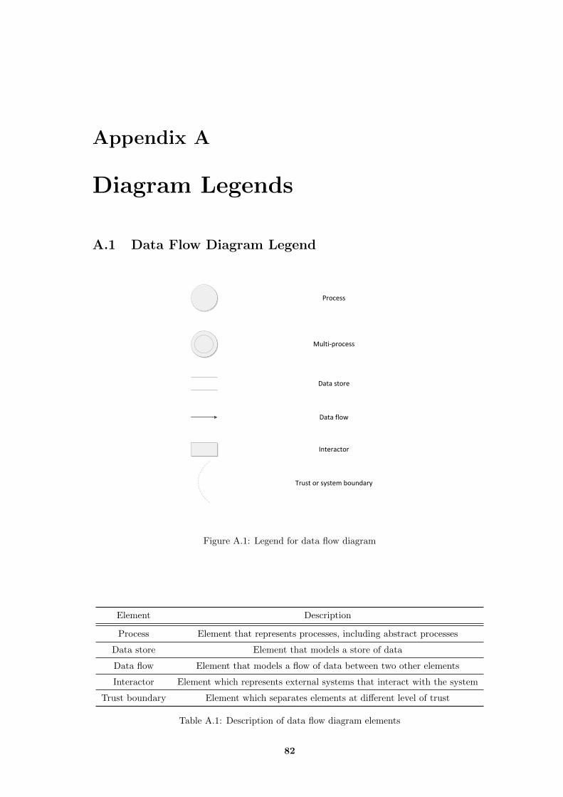
Appendix A
Diagram Legends
A.1 Data Flow Diagram Legend
Process
Data store
Multi-process
Data flow
Interactor
Trust or system boundary
Figure A.1: Legend for data flow diagram
Element Description
Process Element that represents processes, including abstract processes
Data store Element that models a store of data
Data flow Element that models a flow of data between two other elements
Interactor Element which represents external systems that interact with the system
Trust boundary Element which separates elements at different level of trust
Table A.1: Description of data flow diagram elements
82
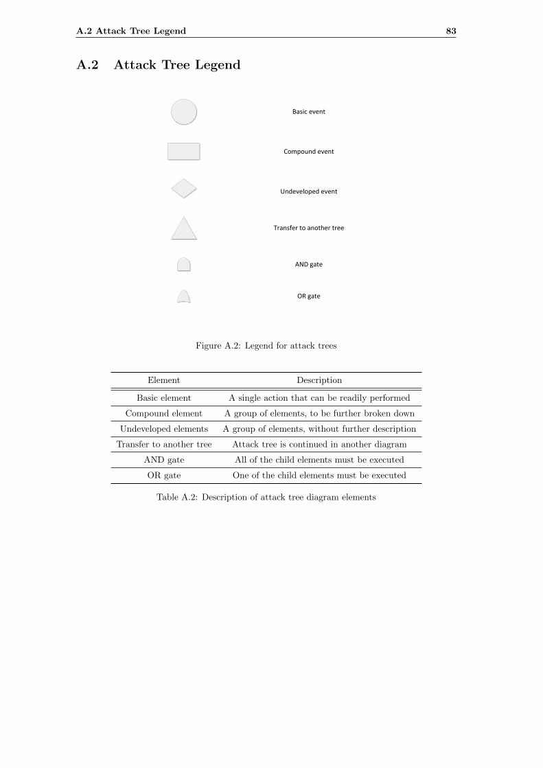
A.2 Attack Tree Legend 83
A.2 Attack Tree Legend
Basic event
Compound event
Undeveloped event
Transfer to another tree
AND gate
OR gate
Figure A.2: Legend for attack trees
Element Description
Basic element A single action that can be readily performed
Compound element A group of elements, to be further broken down
Undeveloped elements A group of elements, without further description
Transfer to another tree Attack tree is continued in another diagram
AND gate All of the child elements must be executed
OR gate One of the child elements must be executed
Table A.2: Description of attack tree diagram elements
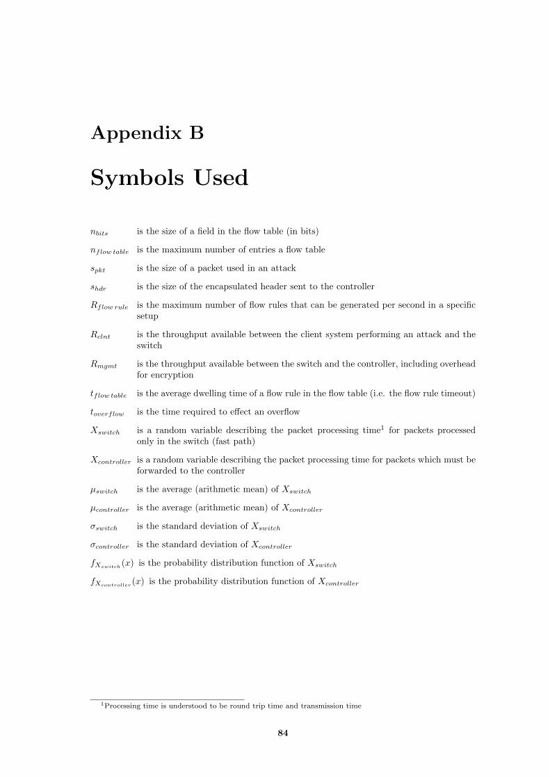
Appendix B
Symbols Used
nbits is the size of a field in the flow table (in bits)
nflow table is the maximum number of entries a flow table
spkt is the size of a packet used in an attack
shdr is the size of the encapsulated header sent to the controller
Rflow rule is the maximum number of flow rules that can be generated per second in a specificsetup
Rclnt is the throughput available between the client system performing an attack and theswitch
Rmgmt is the throughput available between the switch and the controller, including overheadfor encryption
tflow table is the average dwelling time of a flow rule in the flow table (i.e. the flow rule timeout)
toverflow is the time required to effect an overflow
Xswitch is a random variable describing the packet processing time1 for packets processedonly in the switch (fast path)
Xcontroller is a random variable describing the packet processing time for packets which must beforwarded to the controller
µswitch is the average (arithmetic mean) of Xswitch
µcontroller is the average (arithmetic mean) of Xcontroller
σswitch is the standard deviation of Xswitch
σcontroller is the standard deviation of Xcontroller
fXswitch(x) is the probability distribution function of Xswitch
fXcontroller(x) is the probability distribution function of Xcontroller
1Processing time is understood to be round trip time and transmission time
84

Appendix C
Attack Trees
On the following pages, the full attack tree is reproduced.
85
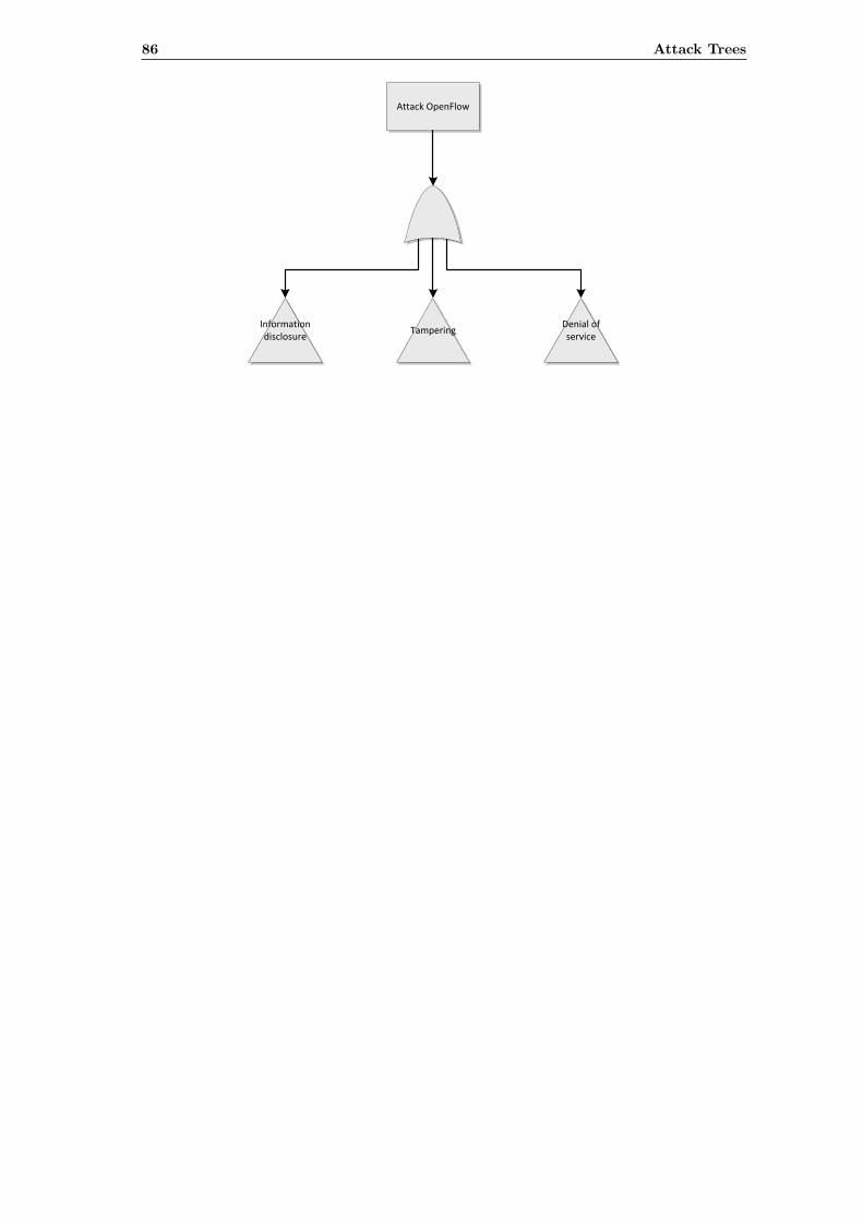
Attack OpenFlow
Information disclosure
TamperingDenial of service
86 Attack Trees
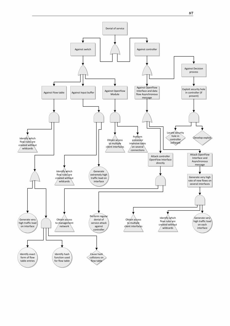
Denial of service
Against switch Against controller
Against Flow table
Against OpenFlow Interface and data flow Asynchronous
message
Against OpenFlow Module
Generate very high traffic load
on interface
Exploit security hole in controller (if
present)Against Input buffer
Attack controller OpenFlow Interface
directly
Perform regular denial of
service attack against
controller
Attack OpenFlow Interface and Asynchronous
message
Generate very high rate of new flows on
several interfaces
Generate very high traffic load
on each interface
Generate extremely high traffic load on
interface
Obtain access to multiple
client interfaces
Obtain access to multiple
client interfaces
Obtain access to management
network
Locate security hole in
controller software
Develop exploitPerform processor
intensive tasks on several
connections
Identify which flow rules are
created without wildcards
Identify which flow rules are
created without wildcards
Identify which flow rules are
created without wildcards
Against Decision process
Identify exact form of flow table entries
Identify hash function used for flow table
Cause hash collisions on
flow table
87
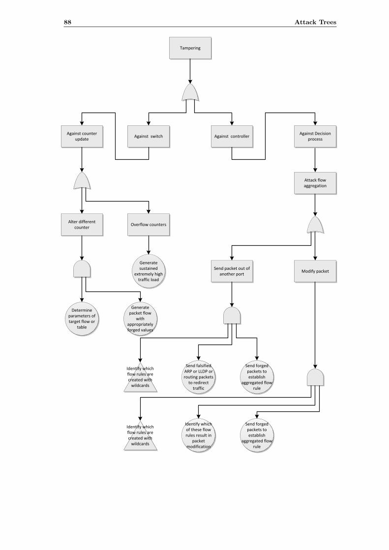
Tampering
Against switch
Overflow counters
Attack flow aggregation
Against controller
Alter different counter
Send packet out of another port
Modify packet
Generate sustained
extremely high traffic load
Determine parameters of target flow or
table
Generate packet flow
with appropriately forged values
Send falsified ARP or LLDP or routing packets
to redirect traffic
Send forged packets to establish
aggregated flow rule
Identify which of these flow rules result in
packet modification
Identify which flow rules are created with
wildcards
Identify which flow rules are created with
wildcards
Send forged packets to establish
aggregated flow rule
Against counter update
Against Decision process
88 Attack Trees
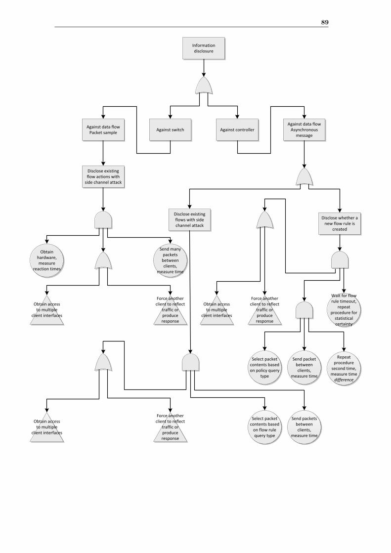
Information disclosure
Against switch Against controller
Disclose existing flows with side channel attack
Disclose whether a new flow rule is
created
Send packets between clients,
measure time
Disclose existing flow actions with
side channel attack
Obtain hardware, measure
reaction times
Send many packets
between clients,
measure time
Send packet between clients,
measure time
Repeat procedure
second time, measure time difference
Obtain access to multiple
client interfaces
Obtain access to multiple
client interfaces
Force another client to reflect
traffic or produce response
Force another client to reflect
traffic or produce response
Obtain access to multiple
client interfaces
Force another client to reflect
traffic or produce response
Wait for flow rule timeout,
repeat procedure for
statistical certainty
Select packet contents based on policy query
type
Select packet contents based
on flow rule query type
Against data flow Packet sample
Against data flow Asynchronous
message
89
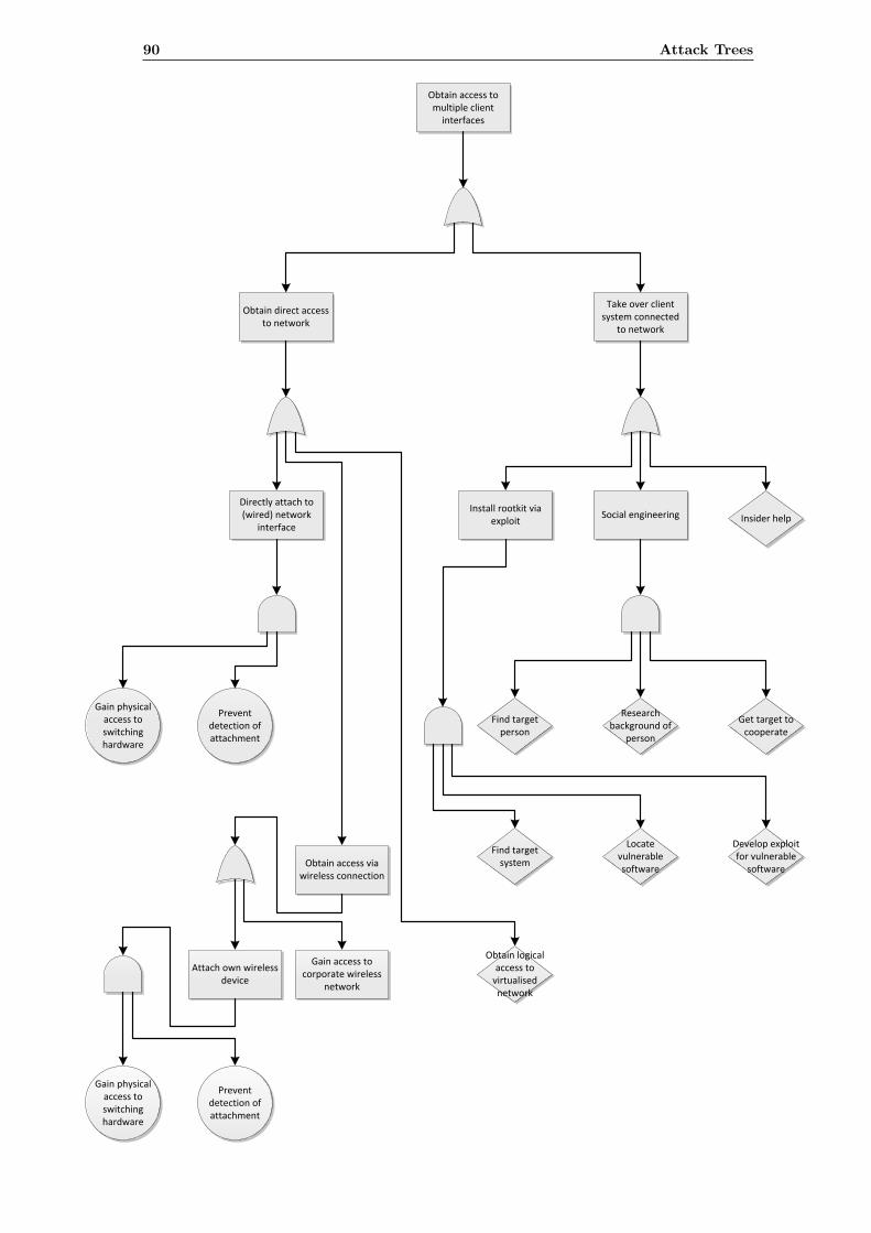
Obtain access to multiple client
interfaces
Obtain direct access to network
Take over client system connected
to network
Social engineeringInstall rootkit via
exploit
Directly attach to (wired) network
interface
Gain physical access to switching hardware
Prevent detection of attachment
Obtain access via wireless connection
Gain access to corporate wireless
network
Attach own wireless device
Gain physical access to switching hardware
Prevent detection of attachment
Find target person
Research background of
person
Get target to cooperate
Find target system
Locate vulnerable software
Develop exploit for vulnerable
software
Insider help
Obtain logical access to
virtualised network
90 Attack Trees
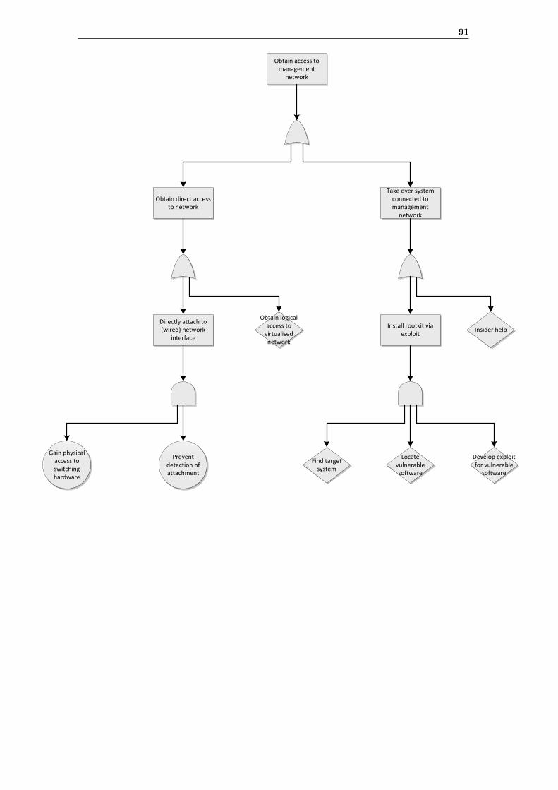
Obtain access to management
network
Obtain direct access to network
Take over system connected to management
network
Install rootkit via exploit
Directly attach to (wired) network
interface
Gain physical access to switching hardware
Prevent detection of attachment
Insider help
Find target system
Locate vulnerable software
Develop exploit for vulnerable
software
Obtain logical access to
virtualised network
91
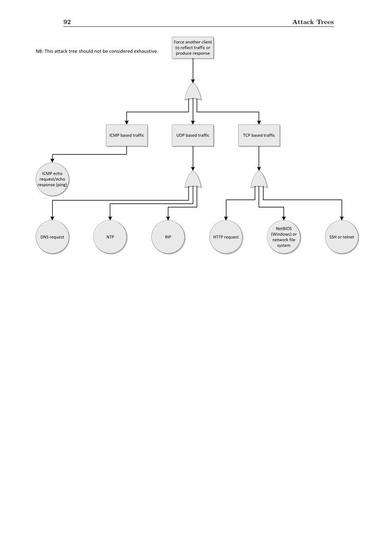
Force another client to reflect traffic or produce response
UDP based trafficICMP based traffic TCP based traffic
ICMP echo request/echo
response (ping)
DNS request NTP RIP HTTP request
NetBIOS (Windows) or network file
system
SSH or telnet
NB: This attack tree should not be considered exhaustive.
92 Attack Trees
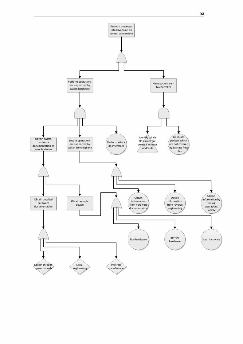
Perform processor intensive tasks on
several connections
Have packets sent to controller
Perform operations not supported by switch hardware
Perform attack on interfaces
Generate packets which
are not covered by existing flow
rules
Obtain switch hardware
documentation or sample device
Buy hardwareBorrow
hardwareSteal hardware
Locate operations not supported by
switch control plane
Obtain information
from hardware documentation
Obtain information from reverse engineering
Obtain information by
timing operations
locally
Identify which flow rules are
created without wildcards
Obtain sample device
Obtain detailed hardware
documentation
Social engineering
Infiltrate manufacturer
Obtain through open channels
93
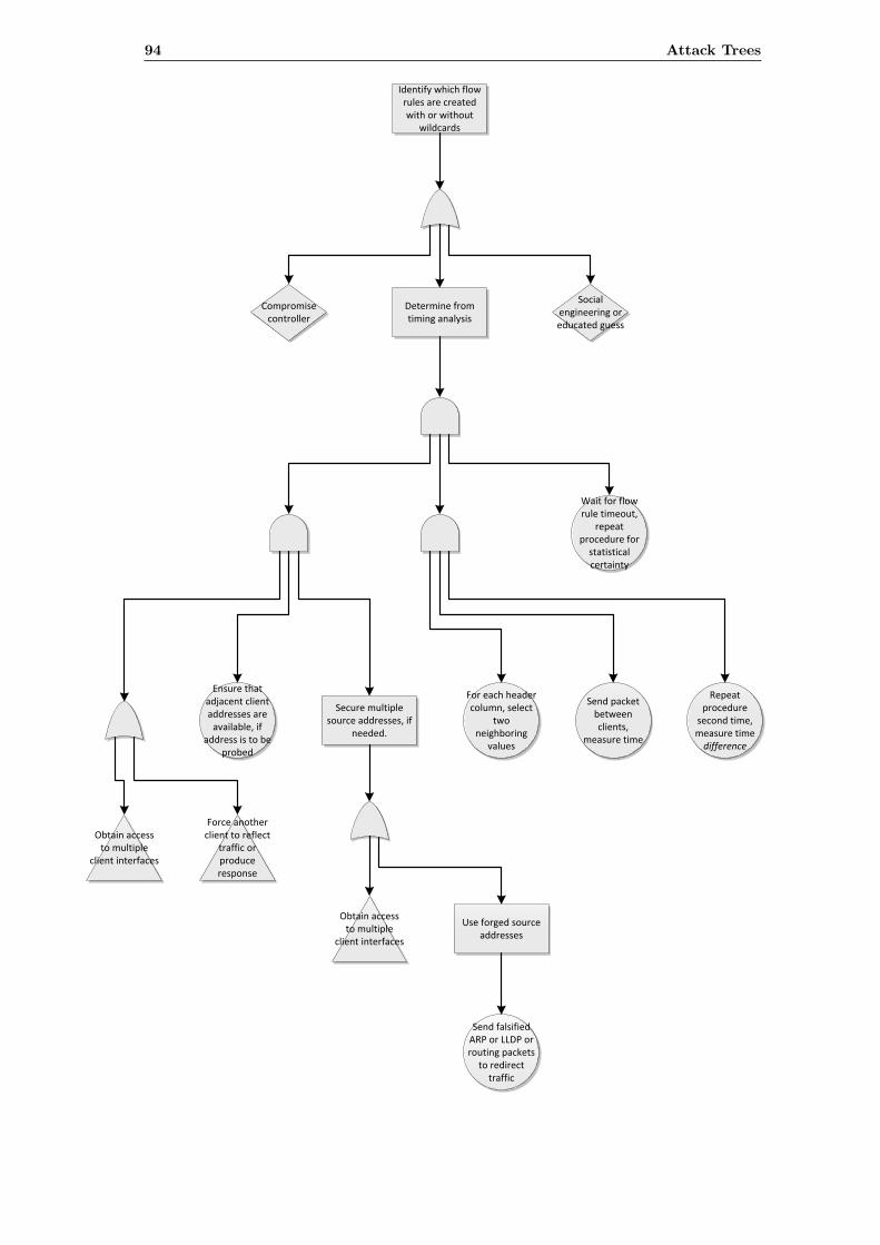
Identify which flow rules are created with or without
wildcards
Determine from timing analysis
Obtain access to multiple
client interfaces
Force another client to reflect
traffic or produce response
Compromise controller
Social engineering or educated guess
Send packet between clients,
measure time
Repeat procedure
second time, measure time difference
For each header column, select
two neighboring
values
Wait for flow rule timeout,
repeat procedure for
statistical certainty
Ensure that adjacent client addresses are
available, if address is to be
probed
Secure multiple source addresses, if
needed.
Send falsified ARP or LLDP or routing packets
to redirect traffic
Obtain access to multiple
client interfaces
Use forged source addresses
94 Attack Trees
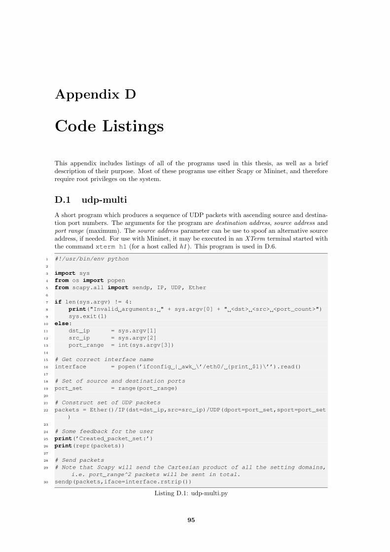
Appendix D
Code Listings
This appendix includes listings of all of the programs used in this thesis, as well as a briefdescription of their purpose. Most of these programs use either Scapy or Mininet, and thereforerequire root privileges on the system.
D.1 udp-multi
A short program which produces a sequence of UDP packets with ascending source and destina-tion port numbers. The arguments for the program are destination address, source address andport range (maximum). The source address parameter can be use to spoof an alternative sourceaddress, if needed. For use with Mininet, it may be executed in an XTerm terminal started withthe command xterm h1 (for a host called h1 ). This program is used in D.6.
1 #!/usr/bin/env python2
3 import sys4 from os import popen5 from scapy.all import sendp, IP, UDP, Ether6
7 if len(sys.argv) != 4:8 print("Invalid arguments: " + sys.argv[0] + " <dst> <src> <port_count>")9 sys.exit(1)
10 else:11 dst_ip = sys.argv[1]12 src_ip = sys.argv[2]13 port_range = int(sys.argv[3])14
15 # Get correct interface name16 interface = popen(’ifconfig | awk \’/eth0/ {print $1}\’’).read()17
18 # Set of source and destination ports19 port_set = range(port_range)20
21 # Construct set of UDP packets22 packets = Ether()/IP(dst=dst_ip,src=src_ip)/UDP(dport=port_set,sport=port_set
)23
24 # Some feedback for the user25 print(’Created packet set:’)26 print(repr(packets))27
28 # Send packets29 # Note that Scapy will send the Cartesian product of all the setting domains,
i.e. port_range^2 packets will be sent in total.30 sendp(packets,iface=interface.rstrip())
Listing D.1: udp-multi.py
95
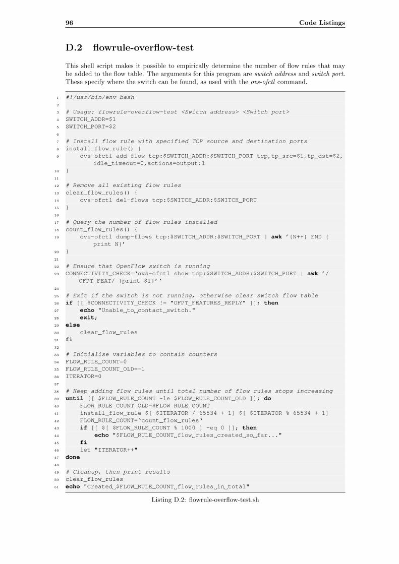
96 Code Listings
D.2 flowrule-overflow-test
This shell script makes it possible to empirically determine the number of flow rules that maybe added to the flow table. The arguments for this program are switch address and switch port.These specify where the switch can be found, as used with the ovs-ofctl command.
1 #!/usr/bin/env bash2
3 # Usage: flowrule-overflow-test <Switch address> <Switch port>4 SWITCH_ADDR=$15 SWITCH_PORT=$26
7 # Install flow rule with specified TCP source and destination ports8 install_flow_rule() {9 ovs-ofctl add-flow tcp:$SWITCH_ADDR:$SWITCH_PORT tcp,tp_src=$1,tp_dst=$2,
idle_timeout=0,actions=output:110 }11
12 # Remove all existing flow rules13 clear_flow_rules() {14 ovs-ofctl del-flows tcp:$SWITCH_ADDR:$SWITCH_PORT15 }16
17 # Query the number of flow rules installed18 count_flow_rules() {19 ovs-ofctl dump-flows tcp:$SWITCH_ADDR:$SWITCH_PORT | awk ’{N++} END {
print N}’20 }21
22 # Ensure that OpenFlow switch is running23 CONNECTIVITY_CHECK=‘ovs-ofctl show tcp:$SWITCH_ADDR:$SWITCH_PORT | awk ’/
OFPT_FEAT/ {print $1}’‘24
25 # Exit if the switch is not running, otherwise clear switch flow table26 if [[ $CONNECTIVITY_CHECK != "OFPT_FEATURES_REPLY" ]]; then27 echo "Unable to contact switch."28 exit;29 else30 clear_flow_rules31 fi32
33 # Initialise variables to contain counters34 FLOW_RULE_COUNT=035 FLOW_RULE_COUNT_OLD=-136 ITERATOR=037
38 # Keep adding flow rules until total number of flow rules stops increasing39 until [[ $FLOW_RULE_COUNT -le $FLOW_RULE_COUNT_OLD ]]; do40 FLOW_RULE_COUNT_OLD=$FLOW_RULE_COUNT41 install_flow_rule $[ $ITERATOR / 65534 + 1] $[ $ITERATOR % 65534 + 1]42 FLOW_RULE_COUNT=‘count_flow_rules‘43 if [[ $[ $FLOW_RULE_COUNT % 1000 ] -eq 0 ]]; then44 echo "$FLOW_RULE_COUNT flow rules created so far..."45 fi46 let "ITERATOR++"47 done48
49 # Cleanup, then print results50 clear_flow_rules51 echo "Created $FLOW_RULE_COUNT flow rules in total"
Listing D.2: flowrule-overflow-test.sh
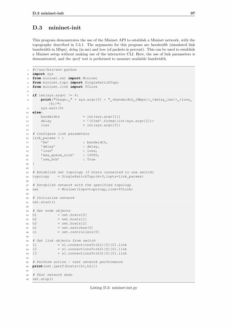
D.3 mininet-init 97
D.3 mininet-init
This program demonstrates the use of the Mininet API to establish a Mininet network, with thetopography described in 5.3.1. The arguments for this program are bandwidth (simulated linkbandwidth in Mbps), delay (in ms) and loss (of packets in percent). This can be used to establisha Mininet setup without making use of the interactive CLI. Here, the use of link parameters isdemonstrated, and the iperf test is performed to measure available bandwidth.
1 #!/usr/bin/env python2 import sys3 from mininet.net import Mininet4 from mininet.topo import SingleSwitchTopo5 from mininet.link import TCLink6
7 if len(sys.argv) != 4:8 print("Usage: " + sys.argv[0] + " <bandwidth [Mbps]> <delay [ms]> <loss
[%]>")9 sys.exit(0)
10 else:11 bandwidth = int(sys.argv[1])12 delay = ’{0}ms’.format(int(sys.argv[2]))13 loss = int(sys.argv[3])14
15 # Configure link parameters16 link_params = {17 ’bw’ : bandwidth,18 ’delay’ : delay,19 ’loss’ : loss,20 ’max_queue_size’ : 10000,21 ’use_htb’ : True22 }23
24 # Establish net topology (3 hosts connected to one switch)25 topology = SingleSwitchTopo(k=3,lopts=link_params)26
27 # Establish network with the specified topology28 net = Mininet(topo=topology,link=TCLink)29
30 # Initialise network31 net.start()32
33 # Get node objects34 h1 = net.hosts[0]35 h2 = net.hosts[1]36 h3 = net.hosts[2]37 s1 = net.switches[0]38 c1 = net.controllers[0]39
40 # Get link objects from switch41 l1 = s1.connectionsTo(h1)[0][0].link42 l2 = s1.connectionsTo(h2)[0][0].link43 l3 = s1.connectionsTo(h3)[0][0].link44
45 # Perform action - test network performance46 print(net.iperf(hosts=[h1,h2]))47
48 # Shut network down49 net.stop()
Listing D.3: mininet-init.py
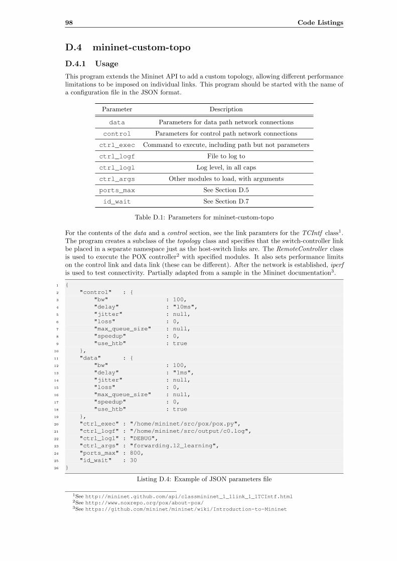
98 Code Listings
D.4 mininet-custom-topo
D.4.1 Usage
This program extends the Mininet API to add a custom topology, allowing different performancelimitations to be imposed on individual links. This program should be started with the name ofa configuration file in the JSON format.
Parameter Description
data Parameters for data path network connections
control Parameters for control path network connections
ctrl_exec Command to execute, including path but not parameters
ctrl_logf File to log to
ctrl_logl Log level, in all caps
ctrl_args Other modules to load, with arguments
ports_max See Section D.5
id_wait See Section D.7
Table D.1: Parameters for mininet-custom-topo
For the contents of the data and a control section, see the link paramters for the TCIntf class1.The program creates a subclass of the topology class and specifies that the switch-controller linkbe placed in a separate namespace just as the host-switch links are. The RemoteController classis used to execute the POX controller2 with specified modules. It also sets performance limitson the control link and data link (these can be different). After the network is established, iperfis used to test connectivity. Partially adapted from a sample in the Mininet documentation3.
1 {2 "control" : {3 "bw" : 100,4 "delay" : "10ms",5 "jitter" : null,6 "loss" : 0,7 "max_queue_size" : null,8 "speedup" : 0,9 "use_htb" : true
10 },11 "data" : {12 "bw" : 100,13 "delay" : "1ms",14 "jitter" : null,15 "loss" : 0,16 "max_queue_size" : null,17 "speedup" : 0,18 "use_htb" : true19 },20 "ctrl_exec" : "/home/mininet/src/pox/pox.py",21 "ctrl_logf" : "/home/mininet/src/output/c0.log",22 "ctrl_logl" : "DEBUG",23 "ctrl_args" : "forwarding.l2_learning",24 "ports_max" : 800,25 "id_wait" : 3026 }
Listing D.4: Example of JSON parameters file
1See http://mininet.github.com/api/classmininet_1_1link_1_1TCIntf.html2See http://www.noxrepo.org/pox/about-pox/3See https://github.com/mininet/mininet/wiki/Introduction-to-Mininet
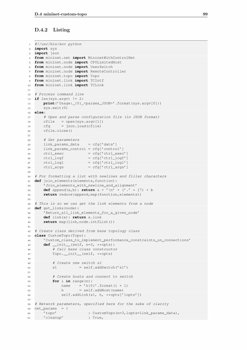
D.4 mininet-custom-topo 99
D.4.2 Listing
1 #!/usr/bin/env python2 import sys3 import json4 from mininet.net import MininetWithControlNet5 from mininet.node import CPULimitedHost6 from mininet.node import UserSwitch7 from mininet.node import RemoteController8 from mininet.topo import Topo9 from mininet.link import TCIntf
10 from mininet.link import TCLink11
12 # Process command line13 if len(sys.argv) != 2:14 print(’Usage: {0} <params_JSON>’.format(sys.argv[0]))15 sys.exit(0)16 else:17 # Open and parse configuration file (in JSON format)18 cfile = open(sys.argv[1])19 cfg = json.load(cfile)20 cfile.close()21
22 # Get parameters23 link_params_data = cfg[’data’]24 link_params_control = cfg[’control’]25 ctrl_exec = cfg[’ctrl_exec’]26 ctrl_logf = cfg[’ctrl_logf’]27 ctrl_logl = cfg[’ctrl_logl’]28 ctrl_args = cfg[’ctrl_args’]29
30 # For formatting a list with newlines and filler characters31 def join_elements(elements,function):32 ’Join elements with newline and alignment’33 def append(a,b): return a + ’\n’ + (’.’ * 17) + b34 return reduce(append,map(function,elements))35
36 # This is so we can get the link elements from a node37 def get_links(node):38 ’Return all link elements for a given node’39 def link(x): return x.link40 return map(link,node.intfList())41
42 # Create class derived from base topology class43 class CustomTopo(Topo):44 ’Custom class to implement performance constraints on connections’45 def __init__(self, n=3, **opts):46 # Call base class constructor47 Topo.__init__(self, **opts)48
49 # Create new switch s150 s1 = self.addSwitch(’s1’)51
52 # Create hosts and connect to switch53 for i in range(n):54 name = ’h{0}’.format(i + 1)55 h = self.addHost(name)56 self.addLink(s1, h, **opts[’lopts’])57
58 # Network parameters, specified here for the sake of clarity59 net_params = {60 ’topo’ : CustomTopo(n=3,lopts=link_params_data),61 ’cleanup’ : True,
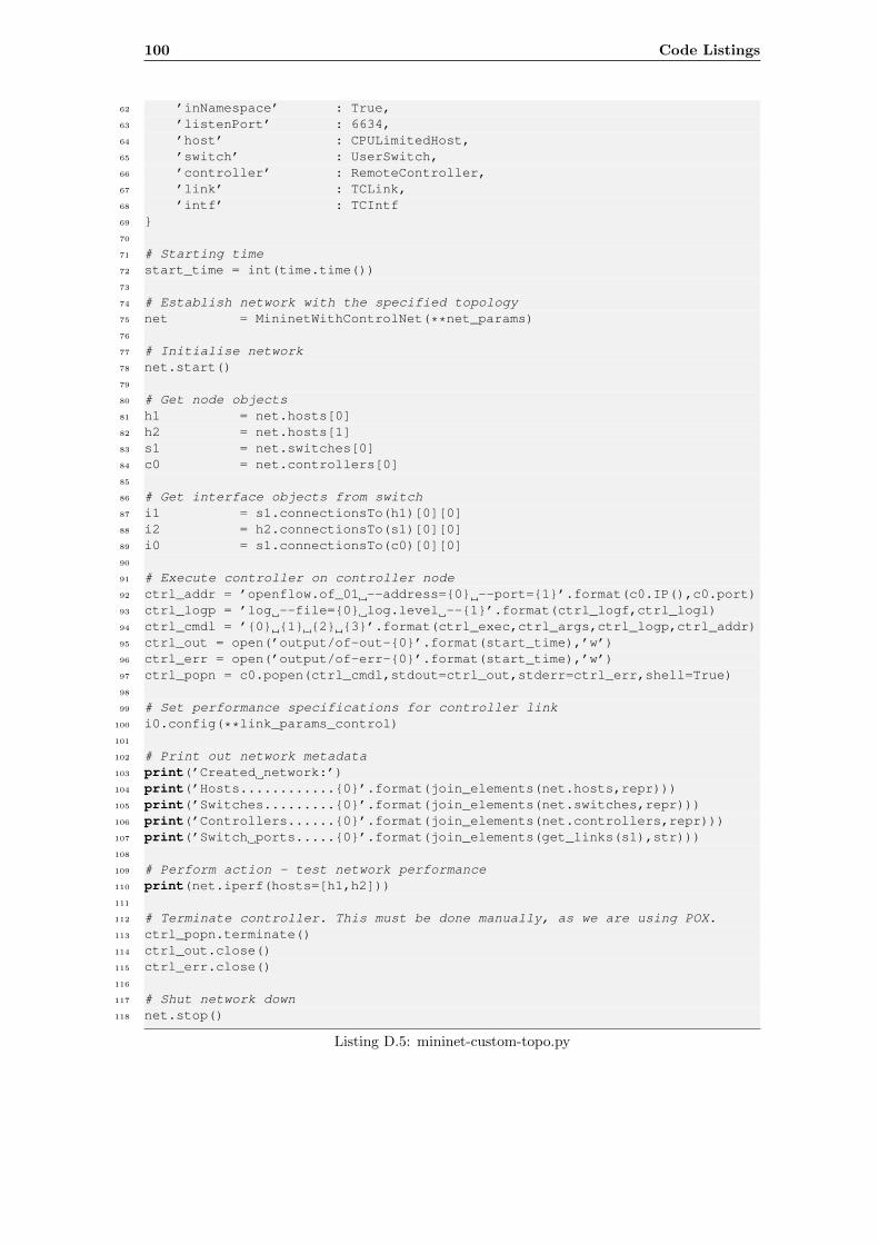
100 Code Listings
62 ’inNamespace’ : True,63 ’listenPort’ : 6634,64 ’host’ : CPULimitedHost,65 ’switch’ : UserSwitch,66 ’controller’ : RemoteController,67 ’link’ : TCLink,68 ’intf’ : TCIntf69 }70
71 # Starting time72 start_time = int(time.time())73
74 # Establish network with the specified topology75 net = MininetWithControlNet(**net_params)76
77 # Initialise network78 net.start()79
80 # Get node objects81 h1 = net.hosts[0]82 h2 = net.hosts[1]83 s1 = net.switches[0]84 c0 = net.controllers[0]85
86 # Get interface objects from switch87 i1 = s1.connectionsTo(h1)[0][0]88 i2 = h2.connectionsTo(s1)[0][0]89 i0 = s1.connectionsTo(c0)[0][0]90
91 # Execute controller on controller node92 ctrl_addr = ’openflow.of_01 --address={0} --port={1}’.format(c0.IP(),c0.port)93 ctrl_logp = ’log --file={0} log.level --{1}’.format(ctrl_logf,ctrl_logl)94 ctrl_cmdl = ’{0} {1} {2} {3}’.format(ctrl_exec,ctrl_args,ctrl_logp,ctrl_addr)95 ctrl_out = open(’output/of-out-{0}’.format(start_time),’w’)96 ctrl_err = open(’output/of-err-{0}’.format(start_time),’w’)97 ctrl_popn = c0.popen(ctrl_cmdl,stdout=ctrl_out,stderr=ctrl_err,shell=True)98
99 # Set performance specifications for controller link100 i0.config(**link_params_control)101
102 # Print out network metadata103 print(’Created network:’)104 print(’Hosts............{0}’.format(join_elements(net.hosts,repr)))105 print(’Switches.........{0}’.format(join_elements(net.switches,repr)))106 print(’Controllers......{0}’.format(join_elements(net.controllers,repr)))107 print(’Switch ports.....{0}’.format(join_elements(get_links(s1),str)))108
109 # Perform action - test network performance110 print(net.iperf(hosts=[h1,h2]))111
112 # Terminate controller. This must be done manually, as we are using POX.113 ctrl_popn.terminate()114 ctrl_out.close()115 ctrl_err.close()116
117 # Shut network down118 net.stop()
Listing D.5: mininet-custom-topo.py
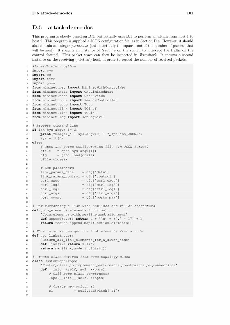
D.5 attack-demo-dos 101
D.5 attack-demo-dos
This program is closely based on D.5, but actually uses D.1 to perform an attack from host 1 tohost 2. This program is supplied a JSON configuration file, as in Section D.4. However, it shouldalso contain an integer ports max (this is actually the square root of the number of packets thatwill be sent). It spawns an instance of tcpdump on the switch to intercept the traffic on thecontrol channel. This packet trace can then be inspected in Wireshark. It spawns a secondinstance on the receiving (“victim”) host, in order to record the number of received packets.
1 #!/usr/bin/env python2 import sys3 import os4 import time5 import json6 from mininet.net import MininetWithControlNet7 from mininet.node import CPULimitedHost8 from mininet.node import UserSwitch9 from mininet.node import RemoteController
10 from mininet.topo import Topo11 from mininet.link import TCIntf12 from mininet.link import TCLink13 from mininet.log import setLogLevel14
15 # Process command line16 if len(sys.argv) != 2:17 print("Usage: " + sys.argv[0] + " <params_JSON>")18 sys.exit(0)19 else:20 # Open and parse configuration file (in JSON format)21 cfile = open(sys.argv[1])22 cfg = json.load(cfile)23 cfile.close()24
25 # Get parameters26 link_params_data = cfg[’data’]27 link_params_control = cfg[’control’]28 ctrl_exec = cfg[’ctrl_exec’]29 ctrl_logf = cfg[’ctrl_logf’]30 ctrl_logl = cfg[’ctrl_logl’]31 ctrl_args = cfg[’ctrl_args’]32 port_count = cfg[’ports_max’]33
34 # For formatting a list with newlines and filler characters35 def join_elements(elements,function):36 ’Join elements with newline and alignment’37 def append(a,b): return a + ’\n’ + (’.’ * 17) + b38 return reduce(append,map(function,elements))39
40 # This is so we can get the link elements from a node41 def get_links(node):42 ’Return all link elements for a given node’43 def link(x): return x.link44 return map(link,node.intfList())45
46 # Create class derived from base topology class47 class CustomTopo(Topo):48 ’Custom class to implement performance constraints on connections’49 def __init__(self, n=3, **opts):50 # Call base class constructor51 Topo.__init__(self, **opts)52
53 # Create new switch s154 s1 = self.addSwitch(’s1’)55
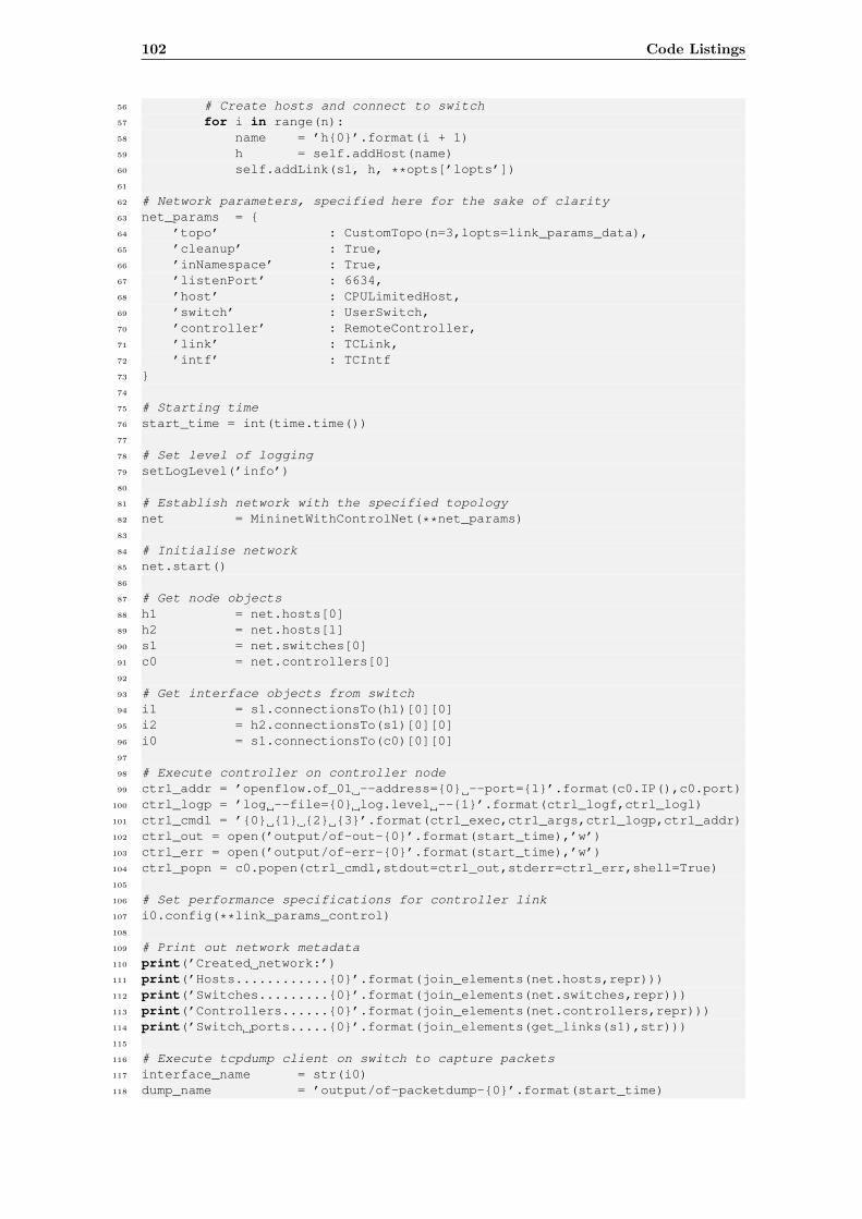
102 Code Listings
56 # Create hosts and connect to switch57 for i in range(n):58 name = ’h{0}’.format(i + 1)59 h = self.addHost(name)60 self.addLink(s1, h, **opts[’lopts’])61
62 # Network parameters, specified here for the sake of clarity63 net_params = {64 ’topo’ : CustomTopo(n=3,lopts=link_params_data),65 ’cleanup’ : True,66 ’inNamespace’ : True,67 ’listenPort’ : 6634,68 ’host’ : CPULimitedHost,69 ’switch’ : UserSwitch,70 ’controller’ : RemoteController,71 ’link’ : TCLink,72 ’intf’ : TCIntf73 }74
75 # Starting time76 start_time = int(time.time())77
78 # Set level of logging79 setLogLevel(’info’)80
81 # Establish network with the specified topology82 net = MininetWithControlNet(**net_params)83
84 # Initialise network85 net.start()86
87 # Get node objects88 h1 = net.hosts[0]89 h2 = net.hosts[1]90 s1 = net.switches[0]91 c0 = net.controllers[0]92
93 # Get interface objects from switch94 i1 = s1.connectionsTo(h1)[0][0]95 i2 = h2.connectionsTo(s1)[0][0]96 i0 = s1.connectionsTo(c0)[0][0]97
98 # Execute controller on controller node99 ctrl_addr = ’openflow.of_01 --address={0} --port={1}’.format(c0.IP(),c0.port)
100 ctrl_logp = ’log --file={0} log.level --{1}’.format(ctrl_logf,ctrl_logl)101 ctrl_cmdl = ’{0} {1} {2} {3}’.format(ctrl_exec,ctrl_args,ctrl_logp,ctrl_addr)102 ctrl_out = open(’output/of-out-{0}’.format(start_time),’w’)103 ctrl_err = open(’output/of-err-{0}’.format(start_time),’w’)104 ctrl_popn = c0.popen(ctrl_cmdl,stdout=ctrl_out,stderr=ctrl_err,shell=True)105
106 # Set performance specifications for controller link107 i0.config(**link_params_control)108
109 # Print out network metadata110 print(’Created network:’)111 print(’Hosts............{0}’.format(join_elements(net.hosts,repr)))112 print(’Switches.........{0}’.format(join_elements(net.switches,repr)))113 print(’Controllers......{0}’.format(join_elements(net.controllers,repr)))114 print(’Switch ports.....{0}’.format(join_elements(get_links(s1),str)))115
116 # Execute tcpdump client on switch to capture packets117 interface_name = str(i0)118 dump_name = ’output/of-packetdump-{0}’.format(start_time)
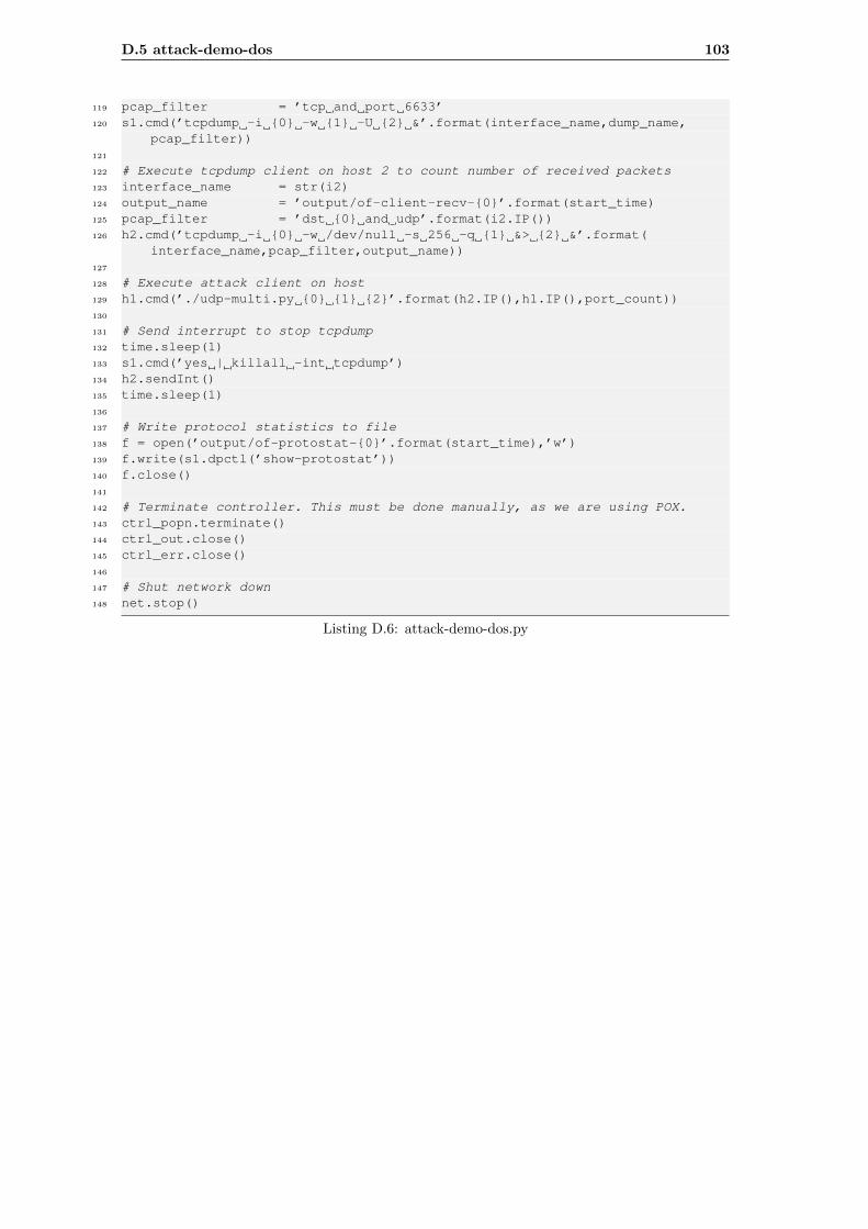
D.5 attack-demo-dos 103
119 pcap_filter = ’tcp and port 6633’120 s1.cmd(’tcpdump -i {0} -w {1} -U {2} &’.format(interface_name,dump_name,
pcap_filter))121
122 # Execute tcpdump client on host 2 to count number of received packets123 interface_name = str(i2)124 output_name = ’output/of-client-recv-{0}’.format(start_time)125 pcap_filter = ’dst {0} and udp’.format(i2.IP())126 h2.cmd(’tcpdump -i {0} -w /dev/null -s 256 -q {1} &> {2} &’.format(
interface_name,pcap_filter,output_name))127
128 # Execute attack client on host129 h1.cmd(’./udp-multi.py {0} {1} {2}’.format(h2.IP(),h1.IP(),port_count))130
131 # Send interrupt to stop tcpdump132 time.sleep(1)133 s1.cmd(’yes | killall -int tcpdump’)134 h2.sendInt()135 time.sleep(1)136
137 # Write protocol statistics to file138 f = open(’output/of-protostat-{0}’.format(start_time),’w’)139 f.write(s1.dpctl(’show-protostat’))140 f.close()141
142 # Terminate controller. This must be done manually, as we are using POX.143 ctrl_popn.terminate()144 ctrl_out.close()145 ctrl_err.close()146
147 # Shut network down148 net.stop()
Listing D.6: attack-demo-dos.py
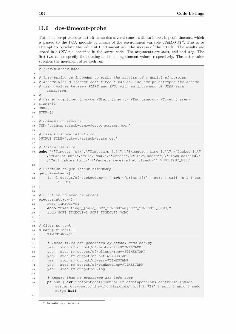
104 Code Listings
D.6 dos-timeout-probe
This shell script executes attack-demo-dos several times, with an increasing soft timeout, whichis passed to the POX module by means of the environment variable TIMEOUT 4. This is toattempt to correlate the value of the timeout and the success of the attack. The results arestored in a CSV file, specified in the source code. The arguments are start, end and step. Thefirst two values specify the starting and finishing timeout values, respectively. The latter valuespecifies the increment after each run.
1 #!/usr/bin/env bash2
3 # This script is intended to probe the results of a denial of service4 # attack with different soft timeout values. The script attempts the attack5 # using values between START and END, with an increment of STEP each
iteration.6 #7 # Usage: dos_timeout_probe <Start timeout> <End timeout> <Timeout step>8 START=$19 END=$2
10 STEP=$311
12 # Command to execute13 CMD="python attack-demo-dos.py params.json"14
15 # File to store results to16 OUTPUT_FILE="output/attack-stats.csv"17
18 # Initialise file19 echo "\"Timeout [s]\",\"Timestamp [s]\",\"Execution time [s]\",\"Packet In\"
,\"Packet Out\",\"Flow Mod\",\"Error\",\"Flows added\",\"Flows deleted\",\"All tables full\",\"Packets received at client\"" > $OUTPUT_FILE
20
21 # Function to get latest timestamp22 get_timestamp() {23 ls -l output/of-packetdump-* | awk ’{print $9}’ | sort | tail -n 1 | cut
-d- -f324 }25
26 # Function to execute attack27 execute_attack() {28 SOFT_TIMEOUT=$129 echo "Executing: [sudo SOFT_TIMEOUT=${SOFT_TIMEOUT} $CMD]"30 sudo SOFT_TIMEOUT=${SOFT_TIMEOUT} $CMD31 }32
33 # Clear up junk34 cleanup_files() {35 TIMESTAMP=$136
37 # These files are generated by attack-demo-dos.py38 yes | sudo rm output/of-protostat-$TIMESTAMP39 yes | sudo rm output/of-client-recv-$TIMESTAMP40 yes | sudo rm output/of-out-$TIMESTAMP41 yes | sudo rm output/of-err-$TIMESTAMP42 yes | sudo rm output/of-packetdump-$TIMESTAMP43 yes | sudo rm output/c0.log44
45 # Ensure that no processes are left over46 ps aux | awk ’/ofprotocol|controller|ofdatapath|ovs-controller|ovsdb-
server|ovs-vswitchd|python|tcpdump/ {print $2}’ | sort | uniq | sudoxargs kill
47
4The value is in seconds
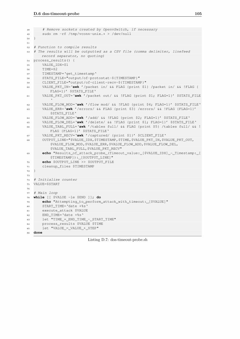
D.6 dos-timeout-probe 105
48 # Remove sockets created by OpenvSwitch, if necessary49 sudo rm -rf /tmp/vconn-unix.* > /dev/null50 }51
52 # Function to compile results53 # The results will be outputted as a CSV file (comma delimiter, linefeed
record separator, no quoting)54 process_results() {55 VALUE_IDX=$156 TIME=$257 TIMESTAMP=‘get_timestamp‘58 STATS_FILE="output/of-protostat-${TIMESTAMP}"59 CLIENT_FILE="output/of-client-recv-${TIMESTAMP}"60 VALUE_PKT_IN=‘awk ’/packet in/ && FLAG {print $1} /packet in/ && !FLAG {
FLAG=1}’ $STATS_FILE‘61 VALUE_PKT_OUT=‘awk ’/packet out/ && !FLAG {print $1; FLAG=1}’ $STATS_FILE
‘62 VALUE_FLOW_MOD=‘awk ’/flow mod/ && !FLAG {print $4; FLAG=1}’ $STATS_FILE‘63 VALUE_ERR=‘awk ’/errors/ && FLAG {print $3} /errors/ && !FLAG {FLAG=1}’
$STATS_FILE‘64 VALUE_FLOW_ADD=‘awk ’/add/ && !FLAG {print $2; FLAG=1}’ $STATS_FILE‘65 VALUE_FLOW_DEL=‘awk ’/delete/ && !FLAG {print $1; FLAG=1}’ $STATS_FILE‘66 VALUE_TABL_FULL=‘awk ’/tables full/ && FLAG {print $5} /tables full/ && !
FLAG {FLAG=1}’ $STATS_FILE‘67 VALUE_PKT_RECV=‘awk ’/captured/ {print $1}’ $CLIENT_FILE‘68 OUTPUT_LINE="$VALUE_IDX,$TIMESTAMP,$TIME,$VALUE_PKT_IN,$VALUE_PKT_OUT,
$VALUE_FLOW_MOD,$VALUE_ERR,$VALUE_FLOW_ADD,$VALUE_FLOW_DEL,$VALUE_TABL_FULL,$VALUE_PKT_RECV"
69 echo "Results of attack probe (Timeout value: [$VALUE_IDX] - Timestamp: [$TIMESTAMP]): [$OUTPUT_LINE]"
70 echo $OUTPUT_LINE >> $OUTPUT_FILE71 cleanup_files $TIMESTAMP72 }73
74 # Initialise counter75 VALUE=$START76
77 # Main loop78 while [[ $VALUE -le $END ]]; do79 echo "Attempting to perform attack with timeout: [$VALUE]"80 START_TIME=‘date +%s‘81 execute_attack $VALUE82 END_TIME=‘date +%s‘83 let "TIME = END_TIME - START_TIME"84 process_results $VALUE $TIME85 let "VALUE = VALUE + STEP"86 done
Listing D.7: dos-timeout-probe.sh
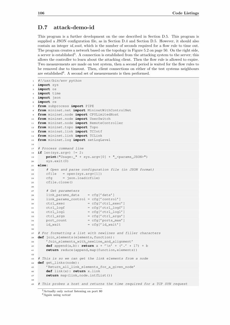
106 Code Listings
D.7 attack-demo-id
This program is a further development on the one described in Section D.5. This program issupplied a JSON configuration file, as in Section D.4 and Section D.5. However, it should alsocontain an integer id wait, which is the number of seconds required for a flow rule to time out.The program creates a network based on the topology in Figure 5.2 on page 50. On the right side,a server is established5. A connection is established from the attacking system to the server; thisallows the controller to learn about the attacking client. Then the flow rule is allowed to expire.Two measurements are made on test system, then a second period is waited for the flow rules tobe removed due to timeout. Then, client connections on either of the test systems neighboursare established6. A second set of measurements is then performed.
1 #!/usr/bin/env python2 import sys3 import os4 import time5 import json6 import re7 from subprocess import PIPE8 from mininet.net import MininetWithControlNet9 from mininet.node import CPULimitedHost
10 from mininet.node import UserSwitch11 from mininet.node import RemoteController12 from mininet.topo import Topo13 from mininet.link import TCIntf14 from mininet.link import TCLink15 from mininet.log import setLogLevel16
17 # Process command line18 if len(sys.argv) != 2:19 print("Usage: " + sys.argv[0] + " <params_JSON>")20 sys.exit(0)21 else:22 # Open and parse configuration file (in JSON format)23 cfile = open(sys.argv[1])24 cfg = json.load(cfile)25 cfile.close()26
27 # Get parameters28 link_params_data = cfg[’data’]29 link_params_control = cfg[’control’]30 ctrl_exec = cfg[’ctrl_exec’]31 ctrl_logf = cfg[’ctrl_logf’]32 ctrl_logl = cfg[’ctrl_logl’]33 ctrl_args = cfg[’ctrl_args’]34 port_count = cfg[’ports_max’]35 id_wait = cfg[’id_wait’]36
37 # For formatting a list with newlines and filler characters38 def join_elements(elements,function):39 ’Join elements with newline and alignment’40 def append(a,b): return a + ’\n’ + (’.’ * 17) + b41 return reduce(append,map(function,elements))42
43 # This is so we can get the link elements from a node44 def get_links(node):45 ’Return all link elements for a given node’46 def link(x): return x.link47 return map(link,node.intfList())48
49 # This probes a host and returns the time required for a TCP SYN request
5Actually only netcat listening on port 806Again using netcat
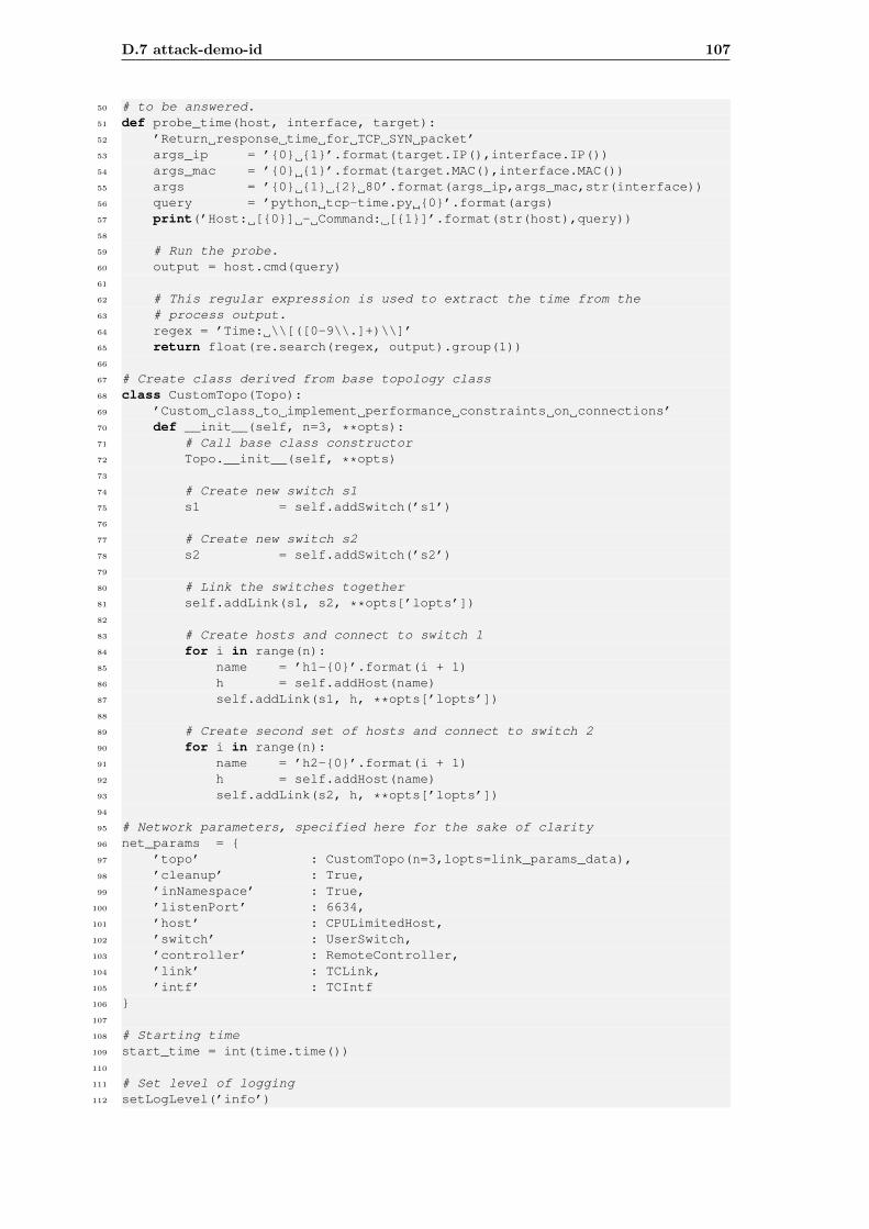
D.7 attack-demo-id 107
50 # to be answered.51 def probe_time(host, interface, target):52 ’Return response time for TCP SYN packet’53 args_ip = ’{0} {1}’.format(target.IP(),interface.IP())54 args_mac = ’{0} {1}’.format(target.MAC(),interface.MAC())55 args = ’{0} {1} {2} 80’.format(args_ip,args_mac,str(interface))56 query = ’python tcp-time.py {0}’.format(args)57 print(’Host: [{0}] - Command: [{1}]’.format(str(host),query))58
59 # Run the probe.60 output = host.cmd(query)61
62 # This regular expression is used to extract the time from the63 # process output.64 regex = ’Time: \\[([0-9\\.]+)\\]’65 return float(re.search(regex, output).group(1))66
67 # Create class derived from base topology class68 class CustomTopo(Topo):69 ’Custom class to implement performance constraints on connections’70 def __init__(self, n=3, **opts):71 # Call base class constructor72 Topo.__init__(self, **opts)73
74 # Create new switch s175 s1 = self.addSwitch(’s1’)76
77 # Create new switch s278 s2 = self.addSwitch(’s2’)79
80 # Link the switches together81 self.addLink(s1, s2, **opts[’lopts’])82
83 # Create hosts and connect to switch 184 for i in range(n):85 name = ’h1-{0}’.format(i + 1)86 h = self.addHost(name)87 self.addLink(s1, h, **opts[’lopts’])88
89 # Create second set of hosts and connect to switch 290 for i in range(n):91 name = ’h2-{0}’.format(i + 1)92 h = self.addHost(name)93 self.addLink(s2, h, **opts[’lopts’])94
95 # Network parameters, specified here for the sake of clarity96 net_params = {97 ’topo’ : CustomTopo(n=3,lopts=link_params_data),98 ’cleanup’ : True,99 ’inNamespace’ : True,
100 ’listenPort’ : 6634,101 ’host’ : CPULimitedHost,102 ’switch’ : UserSwitch,103 ’controller’ : RemoteController,104 ’link’ : TCLink,105 ’intf’ : TCIntf106 }107
108 # Starting time109 start_time = int(time.time())110
111 # Set level of logging112 setLogLevel(’info’)
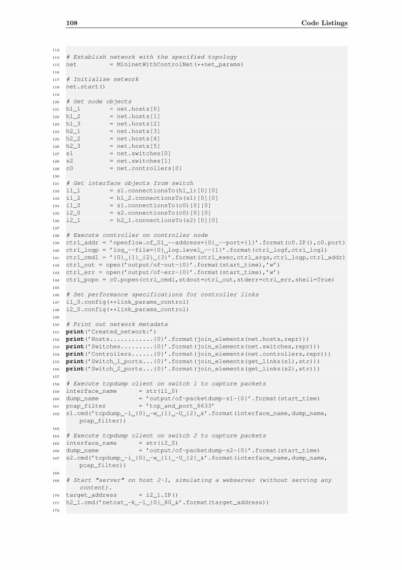
108 Code Listings
113
114 # Establish network with the specified topology115 net = MininetWithControlNet(**net_params)116
117 # Initialise network118 net.start()119
120 # Get node objects121 h1_1 = net.hosts[0]122 h1_2 = net.hosts[1]123 h1_3 = net.hosts[2]124 h2_1 = net.hosts[3]125 h2_2 = net.hosts[4]126 h2_3 = net.hosts[5]127 s1 = net.switches[0]128 s2 = net.switches[1]129 c0 = net.controllers[0]130
131 # Get interface objects from switch132 i1_1 = s1.connectionsTo(h1_1)[0][0]133 i1_2 = h1_2.connectionsTo(s1)[0][0]134 i1_0 = s1.connectionsTo(c0)[0][0]135 i2_0 = s2.connectionsTo(c0)[0][0]136 i2_1 = h2_1.connectionsTo(s2)[0][0]137
138 # Execute controller on controller node139 ctrl_addr = ’openflow.of_01 --address={0} --port={1}’.format(c0.IP(),c0.port)140 ctrl_logp = ’log --file={0} log.level --{1}’.format(ctrl_logf,ctrl_logl)141 ctrl_cmdl = ’{0} {1} {2} {3}’.format(ctrl_exec,ctrl_args,ctrl_logp,ctrl_addr)142 ctrl_out = open(’output/of-out-{0}’.format(start_time),’w’)143 ctrl_err = open(’output/of-err-{0}’.format(start_time),’w’)144 ctrl_popn = c0.popen(ctrl_cmdl,stdout=ctrl_out,stderr=ctrl_err,shell=True)145
146 # Set performance specifications for controller links147 i1_0.config(**link_params_control)148 i2_0.config(**link_params_control)149
150 # Print out network metadata151 print(’Created network:’)152 print(’Hosts............{0}’.format(join_elements(net.hosts,repr)))153 print(’Switches.........{0}’.format(join_elements(net.switches,repr)))154 print(’Controllers......{0}’.format(join_elements(net.controllers,repr)))155 print(’Switch 1 ports...{0}’.format(join_elements(get_links(s1),str)))156 print(’Switch 2 ports...{0}’.format(join_elements(get_links(s2),str)))157
158 # Execute tcpdump client on switch 1 to capture packets159 interface_name = str(i1_0)160 dump_name = ’output/of-packetdump-s1-{0}’.format(start_time)161 pcap_filter = ’tcp and port 6633’162 s1.cmd(’tcpdump -i {0} -w {1} -U {2} &’.format(interface_name,dump_name,
pcap_filter))163
164 # Execute tcpdump client on switch 2 to capture packets165 interface_name = str(i2_0)166 dump_name = ’output/of-packetdump-s2-{0}’.format(start_time)167 s2.cmd(’tcpdump -i {0} -w {1} -U {2} &’.format(interface_name,dump_name,
pcap_filter))168
169 # Start "server" on host 2-1, simulating a webserver (without serving anycontent).
170 target_address = i2_1.IP()171 h2_1.cmd(’netcat -k -l {0} 80 &’.format(target_address))172
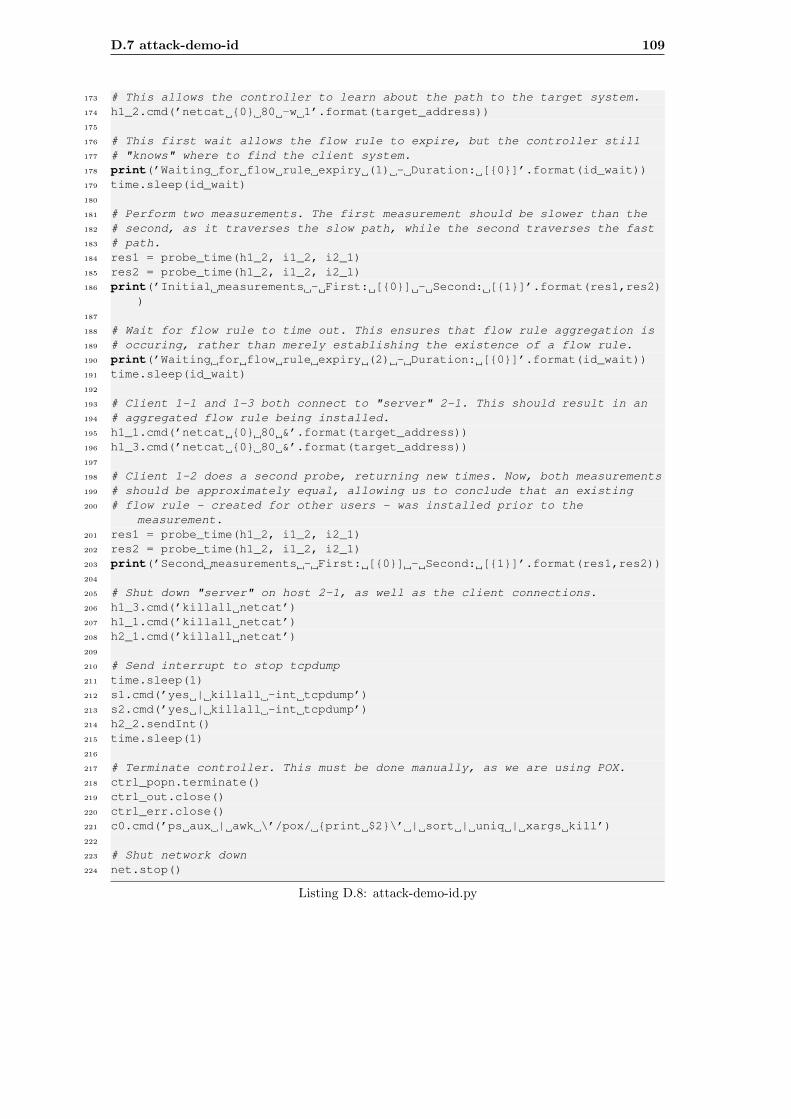
D.7 attack-demo-id 109
173 # This allows the controller to learn about the path to the target system.174 h1_2.cmd(’netcat {0} 80 -w 1’.format(target_address))175
176 # This first wait allows the flow rule to expire, but the controller still177 # "knows" where to find the client system.178 print(’Waiting for flow rule expiry (1) - Duration: [{0}]’.format(id_wait))179 time.sleep(id_wait)180
181 # Perform two measurements. The first measurement should be slower than the182 # second, as it traverses the slow path, while the second traverses the fast183 # path.184 res1 = probe_time(h1_2, i1_2, i2_1)185 res2 = probe_time(h1_2, i1_2, i2_1)186 print(’Initial measurements - First: [{0}] - Second: [{1}]’.format(res1,res2)
)187
188 # Wait for flow rule to time out. This ensures that flow rule aggregation is189 # occuring, rather than merely establishing the existence of a flow rule.190 print(’Waiting for flow rule expiry (2) - Duration: [{0}]’.format(id_wait))191 time.sleep(id_wait)192
193 # Client 1-1 and 1-3 both connect to "server" 2-1. This should result in an194 # aggregated flow rule being installed.195 h1_1.cmd(’netcat {0} 80 &’.format(target_address))196 h1_3.cmd(’netcat {0} 80 &’.format(target_address))197
198 # Client 1-2 does a second probe, returning new times. Now, both measurements199 # should be approximately equal, allowing us to conclude that an existing200 # flow rule - created for other users - was installed prior to the
measurement.201 res1 = probe_time(h1_2, i1_2, i2_1)202 res2 = probe_time(h1_2, i1_2, i2_1)203 print(’Second measurements - First: [{0}] - Second: [{1}]’.format(res1,res2))204
205 # Shut down "server" on host 2-1, as well as the client connections.206 h1_3.cmd(’killall netcat’)207 h1_1.cmd(’killall netcat’)208 h2_1.cmd(’killall netcat’)209
210 # Send interrupt to stop tcpdump211 time.sleep(1)212 s1.cmd(’yes | killall -int tcpdump’)213 s2.cmd(’yes | killall -int tcpdump’)214 h2_2.sendInt()215 time.sleep(1)216
217 # Terminate controller. This must be done manually, as we are using POX.218 ctrl_popn.terminate()219 ctrl_out.close()220 ctrl_err.close()221 c0.cmd(’ps aux | awk \’/pox/ {print $2}\’ | sort | uniq | xargs kill’)222
223 # Shut network down224 net.stop()
Listing D.8: attack-demo-id.py
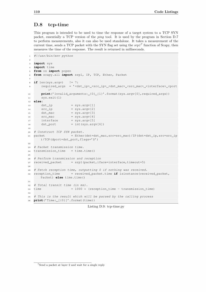
110 Code Listings
D.8 tcp-time
This program is intended to be used to time the response of a target system to a TCP SYNpacket, essentially a TCP version of the ping tool. It is used by the program in Section D.7to perform measurements, also it can also be used standalone. It takes a measurement of thecurrent time, sends a TCP packet with the SYN flag set using the srp1 7 function of Scapy, thenmeasures the time of the response. The result is returned in milliseconds.
1 #!/usr/bin/env python2
3 import sys4 import time5 from os import popen6 from scapy.all import srp1, IP, TCP, Ether, Packet7
8 if len(sys.argv) != 7:9 required_args = ’<dst_ip> <src_ip> <dst_mac> <src_mac> <interface> <port
>’10 print(’Invalid arguments: {0} {1}’.format(sys.argv[0],required_args))11 sys.exit(1)12 else:13 dst_ip = sys.argv[1]14 src_ip = sys.argv[2]15 dst_mac = sys.argv[3]16 src_mac = sys.argv[4]17 interface = sys.argv[5]18 dst_port = int(sys.argv[6])19
20 # Construct TCP SYN packet.21 packet = Ether(dst=dst_mac,src=src_mac)/IP(dst=dst_ip,src=src_ip
)/TCP(dport=dst_port,flags=’S’)22
23 # Packet transmission time.24 transmission_time = time.time()25
26 # Perform transmission and reception27 received_packet = srp1(packet,iface=interface,timeout=5)28
29 # Fetch reception time, outputting 0 if nothing was received.30 reception_time = received_packet.time if isinstance(received_packet,
Packet) else time.time()31
32 # Total transit time (in ms).33 time = 1000 * (reception_time - transmission_time)34
35 # This is the result which will be parsed by the calling process36 print(’Time: [{0}]’.format(time))
Listing D.9: tcp-time.py
7Send a packet at layer 2 and wait for a single reply
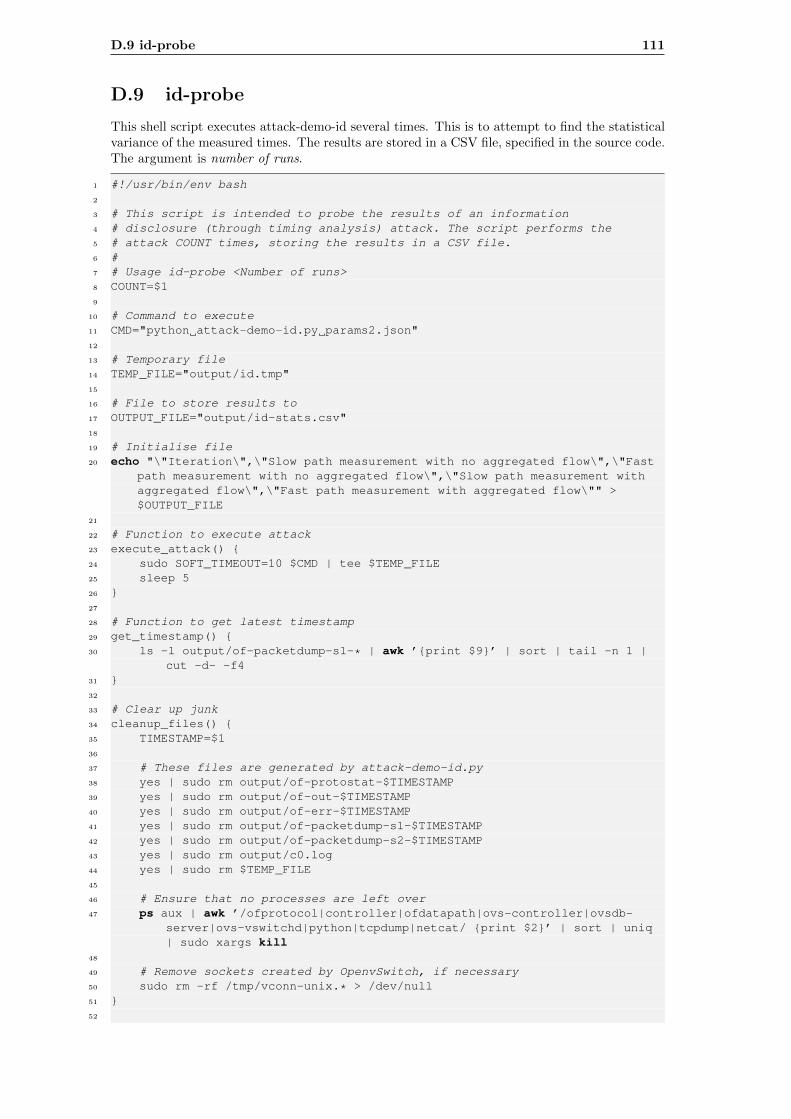
D.9 id-probe 111
D.9 id-probe
This shell script executes attack-demo-id several times. This is to attempt to find the statisticalvariance of the measured times. The results are stored in a CSV file, specified in the source code.The argument is number of runs.
1 #!/usr/bin/env bash2
3 # This script is intended to probe the results of an information4 # disclosure (through timing analysis) attack. The script performs the5 # attack COUNT times, storing the results in a CSV file.6 #7 # Usage id-probe <Number of runs>8 COUNT=$19
10 # Command to execute11 CMD="python attack-demo-id.py params2.json"12
13 # Temporary file14 TEMP_FILE="output/id.tmp"15
16 # File to store results to17 OUTPUT_FILE="output/id-stats.csv"18
19 # Initialise file20 echo "\"Iteration\",\"Slow path measurement with no aggregated flow\",\"Fast
path measurement with no aggregated flow\",\"Slow path measurement withaggregated flow\",\"Fast path measurement with aggregated flow\"" >$OUTPUT_FILE
21
22 # Function to execute attack23 execute_attack() {24 sudo SOFT_TIMEOUT=10 $CMD | tee $TEMP_FILE25 sleep 526 }27
28 # Function to get latest timestamp29 get_timestamp() {30 ls -l output/of-packetdump-s1-* | awk ’{print $9}’ | sort | tail -n 1 |
cut -d- -f431 }32
33 # Clear up junk34 cleanup_files() {35 TIMESTAMP=$136
37 # These files are generated by attack-demo-id.py38 yes | sudo rm output/of-protostat-$TIMESTAMP39 yes | sudo rm output/of-out-$TIMESTAMP40 yes | sudo rm output/of-err-$TIMESTAMP41 yes | sudo rm output/of-packetdump-s1-$TIMESTAMP42 yes | sudo rm output/of-packetdump-s2-$TIMESTAMP43 yes | sudo rm output/c0.log44 yes | sudo rm $TEMP_FILE45
46 # Ensure that no processes are left over47 ps aux | awk ’/ofprotocol|controller|ofdatapath|ovs-controller|ovsdb-
server|ovs-vswitchd|python|tcpdump|netcat/ {print $2}’ | sort | uniq| sudo xargs kill
48
49 # Remove sockets created by OpenvSwitch, if necessary50 sudo rm -rf /tmp/vconn-unix.* > /dev/null51 }52
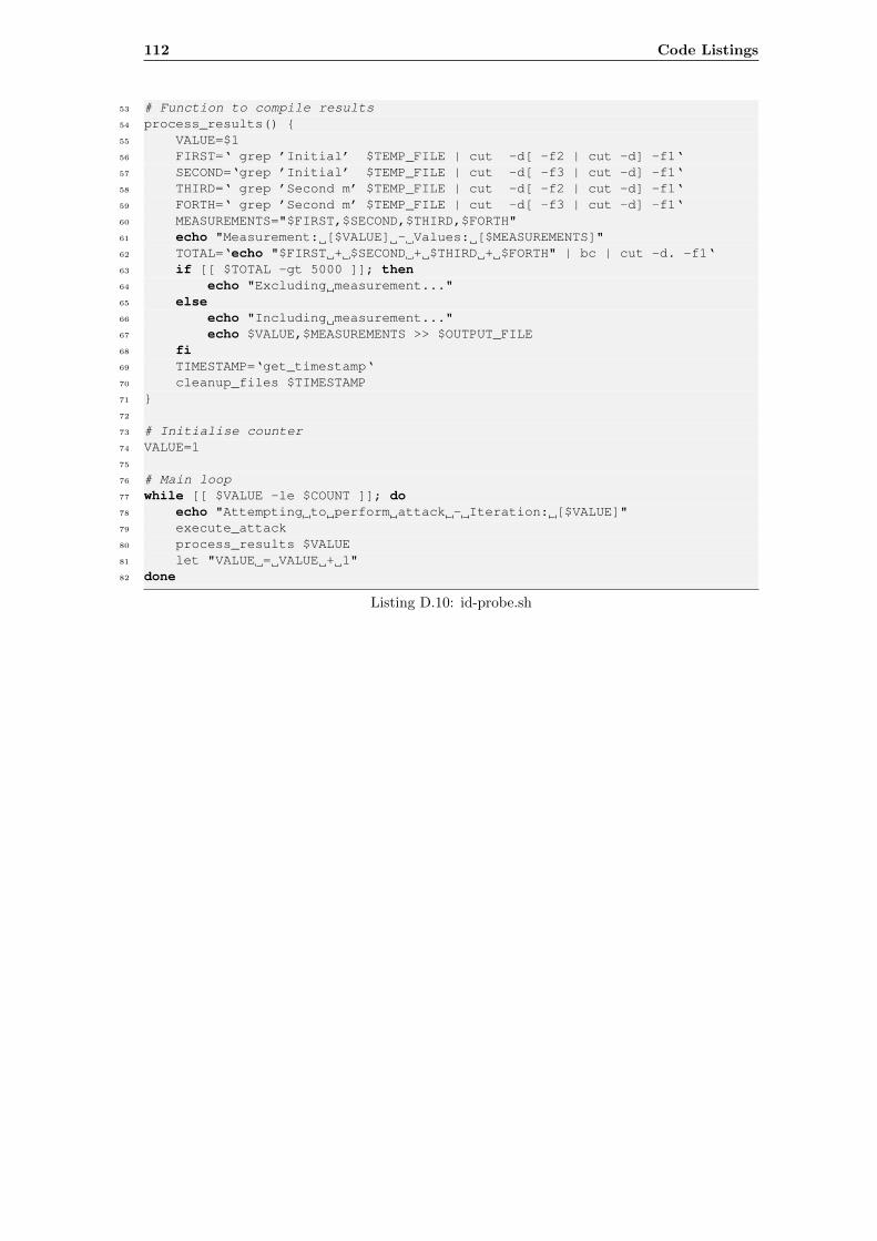
112 Code Listings
53 # Function to compile results54 process_results() {55 VALUE=$156 FIRST=‘ grep ’Initial’ $TEMP_FILE | cut -d[ -f2 | cut -d] -f1‘57 SECOND=‘grep ’Initial’ $TEMP_FILE | cut -d[ -f3 | cut -d] -f1‘58 THIRD=‘ grep ’Second m’ $TEMP_FILE | cut -d[ -f2 | cut -d] -f1‘59 FORTH=‘ grep ’Second m’ $TEMP_FILE | cut -d[ -f3 | cut -d] -f1‘60 MEASUREMENTS="$FIRST,$SECOND,$THIRD,$FORTH"61 echo "Measurement: [$VALUE] - Values: [$MEASUREMENTS]"62 TOTAL=‘echo "$FIRST + $SECOND + $THIRD + $FORTH" | bc | cut -d. -f1‘63 if [[ $TOTAL -gt 5000 ]]; then64 echo "Excluding measurement..."65 else66 echo "Including measurement..."67 echo $VALUE,$MEASUREMENTS >> $OUTPUT_FILE68 fi69 TIMESTAMP=‘get_timestamp‘70 cleanup_files $TIMESTAMP71 }72
73 # Initialise counter74 VALUE=175
76 # Main loop77 while [[ $VALUE -le $COUNT ]]; do78 echo "Attempting to perform attack - Iteration: [$VALUE]"79 execute_attack80 process_results $VALUE81 let "VALUE = VALUE + 1"82 done
Listing D.10: id-probe.sh
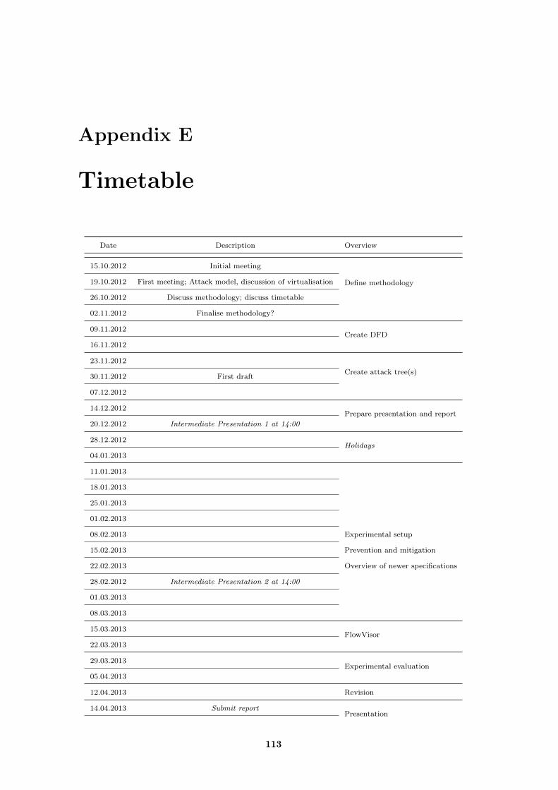
Appendix E
Timetable
Date Description Overview
15.10.2012 Initial meeting
Define methodology19.10.2012 First meeting; Attack model, discussion of virtualisation
26.10.2012 Discuss methodology; discuss timetable
02.11.2012 Finalise methodology?
09.11.2012Create DFD
16.11.2012
23.11.2012
Create attack tree(s)30.11.2012 First draft
07.12.2012
14.12.2012Prepare presentation and report
20.12.2012 Intermediate Presentation 1 at 14:00
28.12.2012Holidays
04.01.2013
11.01.2013
18.01.2013
25.01.2013
01.02.2013
08.02.2013 Experimental setup
15.02.2013 Prevention and mitigation
22.02.2013 Overview of newer specifications
28.02.2012 Intermediate Presentation 2 at 14:00
01.03.2013
08.03.2013
15.03.2013FlowVisor
22.03.2013
29.03.2013Experimental evaluation
05.04.2013
12.04.2013 Revision
14.04.2013 Submit reportPresentation
113

114 Timetable
Date Description Overview
19.04.2013 (No meeting)
25.04.2013 Final presentation at 15:15 (CSG meeting)