Open Systems Adapter-Express3 Integrated Console ...
100
System z10 Open Systems Adapter-Express3 Integrated Console Controller Dual-Port User’s Guide SA23-2266-00
Transcript of Open Systems Adapter-Express3 Integrated Console ...

System z10
Open Systems Adapter-Express3 IntegratedConsole Controller Dual-Port User’s Guide
SA23-2266-00
���


System z10
Open Systems Adapter-Express3 IntegratedConsole Controller Dual-Port User’s Guide
SA23-2266-00
���

NoticeBefore using this information and the products it supports, be sure to read the general information under “Notices” on page79. You should also familiarize yourself with the System z10, System z9 and eServer zSeries Open SystemsAdapter-Express Customer’s Guide and Reference, SA22–7935, Hardware Management Console Operations Guide,SC28-6830, and System z10 Enterprise Class Support Element Operations Guide, Version 2.10.0, SC28-6868.
First Edition, November 2009
This edition, SA23-2266-00, refers to the IBM Open Systems Adapter-Express3 Integrated Console Controller for thefollowing operating systems: z/OS Version 1 Release 2 or higher (5694-A01), and z/OS.e Version 1 Release 3 orhigher (5655-G52), Open Systems Adapter Support Facility for z/Virtual Machine/Enterprise (z/VM) Version 3Release 1, Version 4 Release 2 (Program Number 5654-A17), and Version 4 Release 3 or higher (Program Number5739-A03), OSA/SF for VSE Version 2 Release 2 (part of VSE Central Functions 6.1.1, 5686-066) in VSE/ESAVersion 2 Release 2.6 (5690-VSE) or higher, and to all subsequent releases and modifications until otherwiseindicated in new editions or technical newsletters.
There may be a newer version of this document in PDF format available on Resource Link. Go tohttps://www.ibm.com/servers/resourcelink
and click on Library on the navigation bar. A newer version is indicated by a lower case, alphabetic letter followingthe form number suffix (for example: 00a, 00b, 01a, 01b).
A form for readers’ comments is provided at the back of this publication. If the form has been removed, address yourcomments to:
International Business Machines CorporationDepartment 55JA, Mail Station P3842455 South RoadPoughkeepsie, NY 12601-5400United States of America
FAX (United States & Canada): 1+845+432-9405FAX (Other Countries):
Your International Access Code +1+845+432-9405
IBMLink (United States Customers only): IBMUSM10 (MHVRCFS)
Internet e-mail: [email protected] Wide Web: http://www.ibm.com/s390/os390/webqs.html
When you send information to IBM, you grant IBM a nonexclusive right to use or distribute the information in anyway it believes appropriate without incurring any obligation to you.
© Copyright International Business Machines Corporation 2009.US Government Users Restricted Rights – Use, duplication or disclosure restricted by GSA ADP Schedule Contractwith IBM Corp.

Contents
Figures . . . . . . . . . . . . . . . . . . . . . . . . . . . . v
Tables . . . . . . . . . . . . . . . . . . . . . . . . . . . . vii
About this publication . . . . . . . . . . . . . . . . . . . . . . ixWho should use this publication . . . . . . . . . . . . . . . . . . . ixWhat is included in this publication . . . . . . . . . . . . . . . . . . ixRelated publications . . . . . . . . . . . . . . . . . . . . . . . ixA note on terminology. . . . . . . . . . . . . . . . . . . . . . . ix
Summary of changes . . . . . . . . . . . . . . . . . . . . . . xiSummary of changes for SA23-2266-00 . . . . . . . . . . . . . . . . xi
Chapter 1. Open Systems Adapter-Express3 Integrated Console Controlleroverview . . . . . . . . . . . . . . . . . . . . . . . . . . 1
OSA–ICC introduction . . . . . . . . . . . . . . . . . . . . . . . 1Dual-port network topology . . . . . . . . . . . . . . . . . . . . . 1Planning considerations . . . . . . . . . . . . . . . . . . . . . . 2
Security concerns . . . . . . . . . . . . . . . . . . . . . . . 3OSA-ICC dual-port installation and migration . . . . . . . . . . . . . . 3
Chapter 2. Dual-port connection rules . . . . . . . . . . . . . . . . 5Server definition rules . . . . . . . . . . . . . . . . . . . . . . . 5Client connection rules . . . . . . . . . . . . . . . . . . . . . . 5
Chapter 3. Defining your OSA-ICC configuration . . . . . . . . . . . . 9Defining an OSC CHPID via IOCP . . . . . . . . . . . . . . . . . . 9Steps for defining an OSC CHPID via HCD . . . . . . . . . . . . . . 10
IOCP statements . . . . . . . . . . . . . . . . . . . . . . . 13
Chapter 4. Controlling and configuring an OSA-ICC . . . . . . . . . . 15Hardware Management Console and Support Element console . . . . . . . 15Structure of the OSA-ICC control panels . . . . . . . . . . . . . . . 15Steps for accessing the Advanced Facilities panel . . . . . . . . . . . . 16Advanced Facilities panels . . . . . . . . . . . . . . . . . . . . 19Configuring via panel entry . . . . . . . . . . . . . . . . . . . . 20
View port parameters . . . . . . . . . . . . . . . . . . . . . 20Run port diagnostics . . . . . . . . . . . . . . . . . . . . . . 21Set card mode . . . . . . . . . . . . . . . . . . . . . . . . 23Display client connections . . . . . . . . . . . . . . . . . . . . 24Display active session configuration . . . . . . . . . . . . . . . . 25Display active server configuration. . . . . . . . . . . . . . . . . 27Panel configuration options . . . . . . . . . . . . . . . . . . . 28
Configuring via manual editing . . . . . . . . . . . . . . . . . . . 34Manual configurations options . . . . . . . . . . . . . . . . . . 35
Chapter 5. OSA-ICC programming considerations . . . . . . . . . . . 573270 Client Support . . . . . . . . . . . . . . . . . . . . . . . 57
Chapter 6. eNetwork Personal Communications Configuration . . . . . . 59Steps for customizing a PCOMM session . . . . . . . . . . . . . . . 59
Chapter 7. Error and warning messages . . . . . . . . . . . . . . 63
© Copyright IBM Corp. 2009 iii

Appendix A. Network topology diagrams . . . . . . . . . . . . . . 71Network topology diagram 1 . . . . . . . . . . . . . . . . . . . . 71Network topology diagram 2 . . . . . . . . . . . . . . . . . . . . 71Network topology diagram 3 . . . . . . . . . . . . . . . . . . . . 72Network topology diagram 4 . . . . . . . . . . . . . . . . . . . . 73Network topology diagram 5 . . . . . . . . . . . . . . . . . . . . 74
Appendix B. Error codes that can be returned for an Advanced FacilitiesFunction . . . . . . . . . . . . . . . . . . . . . . . . . . 77
Notices . . . . . . . . . . . . . . . . . . . . . . . . . . . 79Trademarks . . . . . . . . . . . . . . . . . . . . . . . . . . 80
Index . . . . . . . . . . . . . . . . . . . . . . . . . . . . 81
iv System z10 OSA-Express3 ICC Dual-Port Guide

Figures
1. Network topology diagram . . . . . . . . . . . . . . . . . . . . . . . . . . . . 22. Hardware configuration main menu . . . . . . . . . . . . . . . . . . . . . . . . 103. The structure of the configuration panels . . . . . . . . . . . . . . . . . . . . . . 154. Hardware Management Console Workspace panel . . . . . . . . . . . . . . . . . . 175. OSA Advanced Facilities panel. . . . . . . . . . . . . . . . . . . . . . . . . . 176. Standard Channel Advanced Facilities panel. . . . . . . . . . . . . . . . . . . . . 187. Card Specific Advanced Facilities panel . . . . . . . . . . . . . . . . . . . . . . 198. View port parameters panels (1 of 2) . . . . . . . . . . . . . . . . . . . . . . . 209. View port parameters panels (2 of 2) . . . . . . . . . . . . . . . . . . . . . . . 21
10. Run port diagnostics panel . . . . . . . . . . . . . . . . . . . . . . . . . . . 2211. Run port diagnostics warning panel . . . . . . . . . . . . . . . . . . . . . . . . 2212. Run port diagnostics panel . . . . . . . . . . . . . . . . . . . . . . . . . . . 2313. Set card mode panel . . . . . . . . . . . . . . . . . . . . . . . . . . . . . 2414. Display client connections panel . . . . . . . . . . . . . . . . . . . . . . . . . 2415. Display active session configuration panel . . . . . . . . . . . . . . . . . . . . . 2516. Display active server configuration panel . . . . . . . . . . . . . . . . . . . . . . 2717. Panel configuration options panel . . . . . . . . . . . . . . . . . . . . . . . . . 2818. Edit session configuration panel . . . . . . . . . . . . . . . . . . . . . . . . . 2919. Edit session configuration panel . . . . . . . . . . . . . . . . . . . . . . . . . 3120. Edit server configuration panel . . . . . . . . . . . . . . . . . . . . . . . . . . 3221. Validate panel values panel . . . . . . . . . . . . . . . . . . . . . . . . . . . 3322. Display validate panel errors panel . . . . . . . . . . . . . . . . . . . . . . . . 3423. OSC manual configuration panel . . . . . . . . . . . . . . . . . . . . . . . . . 3524. Manual configuration panel . . . . . . . . . . . . . . . . . . . . . . . . . . . 3625. Import source file panel . . . . . . . . . . . . . . . . . . . . . . . . . . . . 3726. Export source file panel . . . . . . . . . . . . . . . . . . . . . . . . . . . . 3827. Import source file via FTP panel . . . . . . . . . . . . . . . . . . . . . . . . . 3928. Export source file via FTP panel . . . . . . . . . . . . . . . . . . . . . . . . . 4029. Valid characters for NAME= tag . . . . . . . . . . . . . . . . . . . . . . . . . 4530. Valid characters for GROUP= tag. . . . . . . . . . . . . . . . . . . . . . . . . 4731. OSC validate source file panel . . . . . . . . . . . . . . . . . . . . . . . . . . 4932. Successful validate source file . . . . . . . . . . . . . . . . . . . . . . . . . . 4933. Activate configuration panel . . . . . . . . . . . . . . . . . . . . . . . . . . . 5034. Display activate configuration errors panel . . . . . . . . . . . . . . . . . . . . . 5035. Debug utilities panel . . . . . . . . . . . . . . . . . . . . . . . . . . . . . 5136. Ping Utility . . . . . . . . . . . . . . . . . . . . . . . . . . . . . . . . . 5137. Trace route utility . . . . . . . . . . . . . . . . . . . . . . . . . . . . . . . 5238. Drop session utility . . . . . . . . . . . . . . . . . . . . . . . . . . . . . . 5339. Logo Controls . . . . . . . . . . . . . . . . . . . . . . . . . . . . . . . . 5440. Query command . . . . . . . . . . . . . . . . . . . . . . . . . . . . . . . 5441. Cancel command panel . . . . . . . . . . . . . . . . . . . . . . . . . . . . 5542. Customize communication screen . . . . . . . . . . . . . . . . . . . . . . . . 5943. Telnet3270 screen . . . . . . . . . . . . . . . . . . . . . . . . . . . . . . 6044. E - Capture — [24x80]. . . . . . . . . . . . . . . . . . . . . . . . . . . . . 6145. Network topology Diagram 1 . . . . . . . . . . . . . . . . . . . . . . . . . . 7146. Network topology Diagram 2 . . . . . . . . . . . . . . . . . . . . . . . . . . 7247. Network topology Diagram 3 . . . . . . . . . . . . . . . . . . . . . . . . . . 7348. Network topology Diagram 4 . . . . . . . . . . . . . . . . . . . . . . . . . . 7449. Network topology Diagram 5 . . . . . . . . . . . . . . . . . . . . . . . . . . 75
© Copyright IBM Corp. 2009 v

vi System z10 OSA-Express3 ICC Dual-Port Guide

Tables
1. Connection rules matrix . . . . . . . . . . . . . . . . . . . . . . . . . . . . . 62. Errors from validate source file. . . . . . . . . . . . . . . . . . . . . . . . . . 633. Warnings from validate source file . . . . . . . . . . . . . . . . . . . . . . . . 694. Errors from validate panels . . . . . . . . . . . . . . . . . . . . . . . . . . . 695. Warnings from validate panels . . . . . . . . . . . . . . . . . . . . . . . . . . 706. Error codes that can be returned for an Advanced Facilities Function . . . . . . . . . . . 77
© Copyright IBM Corp. 2009 vii

viii System z10 OSA-Express3 ICC Dual-Port Guide

About this publication
This document describes the configuration process for the Open SystemsAdapter-Express3 Integrated Console Controller Dual-Port.
Who should use this publicationThis document is intended for the technical staff who will configure the OpenSystems Adapter-Express3 Integrated Console Controller Dual-Port.
What is included in this publicationThis publication contains the following chapters and appendixes:
v Chapter 1, “Open Systems Adapter-Express3 Integrated Console Controlleroverview,” on page 1 is an introduction to the Open Systems Adapter-ExpressIntegrated Console Controller.
v Chapter 2, “Dual-port connection rules,” on page 5 summarizes the rules fordefining either or both physical ports and clients (sessions) during OSA-ICCdual-port configuration.
v Chapter 3, “Defining your OSA-ICC configuration,” on page 9 describes how todefine your OSA-ICC configuration.
v Chapter 4, “Controlling and configuring an OSA-ICC,” on page 15 describes thetasks for configuring your Open Systems Adapter-Express Integrated ConsoleControllers.
v Chapter 5, “OSA-ICC programming considerations,” on page 57 provides briefprogramming tips for 3270 client support.
v Chapter 6, “eNetwork Personal Communications Configuration,” on page 59provides an example of defining a PCOMM 3270 session.
v Chapter 7, “Error and warning messages,” on page 63 describes errors andwarnings issued from the validate source file and validate panels.
v Appendix A, “Network topology diagrams,” on page 71 describes three networktopology diagrams.
Related publications
ImportantPlease ensure that you are using the most recent version of all relateddocumentation.
Other IBM publications that you will find helpful and that you should use along withthis publication include:
v 2074 Usage Tips, GM13–0316.
v IOCP User’s Guide for ICP IOCP, SB10–7037
A note on terminologyThroughout this publication, certain equipment terms and short versions of productnames are used to make the information more easily understood. These are:
CS Communications Server
© Copyright IBM Corp. 2009 ix

1000Base-T1000Base-T Ethernet feature capable of 10, 100, or 1000 Mbps
GbE Gigabit Ethernet feature
OSA Abbreviation for Open Systems Adapter. This document deals exclusivelywith the OSA-Express3 features and may refer to OSA-Express3 as OSA.
OSA-Express3Abbreviation for Open Systems Adapter-Express3 features.
OSA-ICCAbbreviation for Open Systems Adapter-Express Integrated ConsoleController features.
OSC The channel type name for OSA-Express features that are configured asOpen Systems Adapter-Express Integrated Console Controller.
OSD The channel type name for OSA-Express features that run under QueuedDirect Input/Output architecture (QDIO).
OSE The channel type name for OSA-Express features that do not use QDIOarchitecture (typically SNA/APPN/HPR applications).
OSN The channel type name for OSA-Express3 features that use QDIOarchitecture and CDLC protocol.
PCOMMThe Host Access Client Package which includes the eNetwork PersonalCommunications V5.6 emulator.
x System z10 OSA-Express3 ICC Dual-Port Guide

Summary of changes
Summary of changes for SA23-2266-00This is the initial release of the document.
© Copyright IBM Corp. 2009 xi

xii System z10 OSA-Express3 ICC Dual-Port Guide

Chapter 1. Open Systems Adapter-Express3 IntegratedConsole Controller overview
The IBM® Open Systems Adapter-Express Integrated Console Controller (OSA-ICC)is the replacement for 2074 Console Support Controller and local, non-SNA DFT3174 Control Units. Its primary application is to provide connectivity, the networkperformance path is provided by OSD and QDIO modes. The OSA-ICC 3270sessions allow you to IPL your logical partitions within any channel subsystem(CSS) and to provide System Operator/Master consoles for z/OS®, z/OS.e, z/VM®,TPF, and VSE. These sessions can also be used by TSO, VM, or VSE systemprogrammers.
Throughout this document OSA-Express3 may be referred to as OSA.
Each OSA-ICC is capable of handling 120 sessions. The OSA-ICC uses TCP/IPconnections over Ethernet LAN to attach to personal computers (PCs) which arerunning an RFC 2355 compliant TN3270E emulator.
IBM has tested the Host Access Client Package which includes the eNetworkPersonal Communications V5.6 emulator (PCOMM) in CSD3 running underMicrosoft Windows XP + for compatibility, however there is no reason to believethat other RFC 2355 compatible emulators may not work. Please contact theemulator product vendor directly for terms, conditions, prices and other productdetails related to such vendor’s emulator.
For more information on the OSA-ICC single-port feature, see System z9 andEserver zSeries z890 and z990 Open Systems Adapter-Express Integrated ConsoleController User’s Guide, SA22-7990.
OSA–ICC introductionYour system can have one or more OSA-ICC features defined. Before you can usean OSA–ICC as a 3270 control unit, you must configure it. OSA-ICC configurationpanels are accessible on your Hardware Management Console and your SupportElement (SE) console. These panels allow you, the system programmer, tocustomize each OSA-ICC on your system.
Dual-port network topologyThe Dual-Port feature supports two physical ports per CHPID. Each port isindependent and can be independently configured as an OSA-ICC. The serverdefinition for each physical port is restricted to a unique TCP port number andsubnet. These server restrictions allow isolated Local Area Networks (LAN) to becreated for each physical port. The OSA-ICC dual-port function supports 120sessions which can be randomly distributed between the two LANs. Any externalnetwork traffic will only be routed through a common default gateway defined forboth ports. An example illustrating an OSA-ICC dual-port connection is given in thenetwork topology diagram in Figure 1 on page 2.
In addition to the new port a new client connection option has also been introduced.The single client IP per session definition has been expanded to include a range ofIP addresses specified by a user defined IP filter.
© Copyright IBM Corp. 2009 1

This document describes the new panels, tag identifiers and how to perform specifictasks using these components to configure OSA-ICC dual-port.
Figure 1 shows connectivity with OSA-ICC dual-port support where each physicalport (P0, P1) is configured on a different broadcast domain (LAN). Both P0 and P1clients communicate with OSA through the defined TCP port. The remote clients areonly allowed to connect through P0 since the default gateway is associated with thisport. The local clients connected to P1 are restricted to communicate only with theclients of that subnet. For more examples of different OSA-ICC dual-port networktopologies, see Appendix A, “Network topology diagrams,” on page 71.
Planning considerationsOSA-ICC offers significant consolidation of console support. Consequently, it isstrongly recommended that production environments use redundant configurationswhere operator consoles are defined through two different OSA-ICC LANs on twodifferent OSA cards to prevent the loss of console control in the unlikely event of afailure. The OSA-ICC documentation and support material assumes this is the caseand shows appropriate configuration information for one OSA-ICC feature.
Figure 1. Network topology diagram
2 System z10 OSA-Express3 ICC Dual-Port Guide

Security concernsDepending on how you connect your TN3270E client systems, you may or may nothave security concerns. An alternative to physically local LANs is the use of one ormore Virtual Private Networks (VPNs). The use of an external device or software isnecessary to provide additional security for clients attaching to a host via OSA-ICC.
OSA-ICC dual-port installation and migrationPreviously, OSA-ICC supported the definition of a single physical port for eachCHPID. The new OSA-ICC dual-port supports two physical port definitions perCHPID. For initial installation of the OSC dual-port CHPIDs the migration processincludes installing the dual-port driver, then following dual-port panel instructions toconfigure the server and client interface. When defining either or both physical portservers for the first time each physical port will be in the default state and there willbe no sessions defined.
The migration process from single port to dual-port for a CHPID that was previouslydefined is automatic. After installing the dual-port driver the current single portserver definition will be converted to the OSA-ICC dual-port physical port 0definition. The second physical port will remain in its defaulted state. All dual-portspecific configuration components will be automatically added to the panel and themanual configuration file to allow validation of the physical port server and clientdefinitions. All previously defined sessions will also be transferred over as physicalport 0 defined sessions.
In the event that the CHPID needs to revert to single port microcode after migratingto dual-port support, it is recommended that the configuration file associated withthe CHPID is saved. If any unexpected conditions occur after applying single portmicrocode load, reset the CHPID to default import and apply the savedconfiguration file.
Chapter 1. Open Systems Adapter-Express3 Integrated Console Controller overview 3

4 System z10 OSA-Express3 ICC Dual-Port Guide

Chapter 2. Dual-port connection rules
The OSA-ICC dual-port configuration process includes rules for defining either orboth physical ports and clients (sessions). The new rules introduced for physicalport server definition allow each physical port to function independently. The serverdefinition rules and client connection rules are described in this chapter.
Server definition rulesThe following server definition rules apply when defining both physical ports:
v There is a unique TCP Port number for each physical port
v There is a different subnet for each physical port host IP
v There is a single defined common gateway
Client connection rulesWhen the client is connecting to the OSA-ICC, the client gets assigned to one of apossible 120 sessions based on what is in the client session table. If the client doesnot meet the criteria described below, or there are no more free sessions, thatclient’s connection is refused. Connection rules deal with the criteria that is issuedfor a client’s assignment to sessions.
Connection criteria is based on two rules:
v What can be defined in the session table
v How a client is assigned to a session
There are two elements that rules deal with:
v The client’s IP
v The LU name (also called group name)
The following can be defined in the session table (via panels or via source file):
v Each session has to have at least one element; for example, either LU name oran IP address.
v A session can have the client’s IP and the LU name.
v A session may have only an LU name or only a client’s IP.
v The same LU name cannot be specified in multiple images (CSS/IIDs). It may,however, be used multiple times within the same image.
v If a session has the LU name and IP defined, then another session cannot havethat same LU name without also specifying an IP address. However, it is okay ifLU is reused with the same or different IP address. If you attempt to use the LUname by itself, you will get return code 1223 or 1224, depending on what sessionwas defined first (one with both LU name and IP address, or one with just LUname). For example:session1 : CSS= 1 MIFID= 1 GROUP= "LU1" CLIENT_IP= 10.10.10.1session2 : CSS= 1 MIFID= 1 GROUP= "LU1" -
These two sessions are in conflict - this would be an error.
Example 2:session1 : CSS= 1 MIFID= 1 GROUP= "LU1" CLIENT_IP= 10.10.10.1session2 : CSS= 1 MIFID= 1 GROUP= "LU1" CLIENT_IP= 10.10.10.2
© Copyright IBM Corp. 2009 5

These two sessions are not in conflict.
Example 3:session1 : CSS= 1 MIFID= 1 GROUP= "LU1" CLIENT_IP= 10.10.10.1session2 : CSS= 1 MIFID=1 GROUP= "LU2" -
These two sessions are not in conflict - because session 2 uses a different LU.
v IP has to be unique per partition when no LU is specified.
This is how clients are assigned to a session:
v If the client has specified an LU name, then the first available session with thatLU name will be considered. Furthermore, if that session entry has a client’s IPaddress specified, the address of the incoming client must also match.
v If the client has specified an LU name, then first available session with that LUname will be considered. Furthermore, if that session entry has NO client’s IPaddress specified, the address of the incoming client does not have to match.
v If the client has not specified an LU name, the first available session without anLU name will be considered. Furthermore, the IP address of the incoming clientmust match that session’s client IP address.
v IP filter rule applies whenever the Client IP is defined.
Table 1. Connection rules matrix
Rule Sessionconfiguration
Client’s configuration Effect
1 No LU name,and no IP
Not allowed No Connection
2 Unique LU namespecified
Defined LU Connection
3 LU namespecified multipletimes and uniqueto this partition
Defined LU Connection
No/mismatch LU or defined inmultiple CSS/image
No Connection
6 System z10 OSA-Express3 ICC Dual-Port Guide

Table 1. Connection rules matrix (continued)
4 LU name andclient IP addressspecified
Client specifiedLU name
Client IP address
Is valid Client does nothave an IPaddress
No Connection
Client has an IPaddress, andthere’s noOSA-ICC clientIP filter defined
Connection
Client has an IPaddress and itmatches theOSA-ICC IP filter
Connection
The client hasan IP addressand it does notmatch theOSA-ICC IP filter
No Connection
Is not valid Client does nothave an IPaddress
No Connection
Client has an IPaddress, andthere’s noOSA-ICC clientIP filter defined
No Connection
Client has an IPaddress and itmatches theOSA-ICC IP filter
No Connection
The client hasan IP addressand it does notmatch theOSA-ICC IP filter
No Connection
5 Unique IPspecified
IP good Connection
IP bad or defined in multipleCSS/images
No Connection
6 Client IPspecified multipletimes and uniqueto this partition
Defined IP Connection
No/mismatch IP or defined inmultiple CSS/images
No Connection
Chapter 2. Dual-port connection rules 7

8 System z10 OSA-Express3 ICC Dual-Port Guide

Chapter 3. Defining your OSA-ICC configuration
There are four different possible Channel Path ID (CHPID) types for OSA-Express3channels. An OSA-Express3 channel may be defined as an OSE, OSD, OSN, or anOSC CHPID. An OSA-ICC is an OSC CHPID. In order for your system to recognizean OSC CHPID, you must define the CHPID as such in your Input/OutputConfiguration Dataset (IOCDS) via the Hardware Configuration Definition (HCD) orthe Input/Output Configuration Program (IOCP).
You must define in the IOCDS each OSA-Express3 1000Base-T port you wish touse. Each OSA-ICC function requires a unique CHPID, control unit, and devicedefinition. These definitions are made using HCD or IOCP, which defines theOSA-Express3 feature to the I/O hardware configuration.
A TN3270E session is associated with a single device in one logical partition. Youmay configure a maximum of 120 sessions to be used. However, the IOCDS cancontain more than 120 configurable devices.
Defining an OSC CHPID via IOCPYou can define each OSA-Express3 1000Base-T port you wish to use in the IOCDSvia IOCP or HCD. The following is a sample IOCP configuration for defining anOSA-ICC channel. For instructions on defining an OSA-ICC channel via HCD, see“Steps for defining an OSC CHPID via HCD” on page 10.RESOURCE PART=((CSS(0),(LP01,1),(LP02,2),(LP05,5)), *
(CSS(1),(MVS1,3),(VM2,5)), *(CSS(2),(VSE,8),(LP34,4),(LP3A,A)))
CHPID PCHID=1C0,PATH=(CSS(0,1,2),80),TYPE=OSCCNTLUNIT CUNUMBR=1000,PATH=((CSS(0),80),(CSS(1),80),(CSS(2),80)), *
UNIT=OSCIODEVICE ADDRESS=(2400,96),CUNUMBR=1000,UNIT=3270,MODEL=X
RESOURCE PART: The RESOURCE statement defines all of the logical partitionsand the logical channel subsystems (LCSSs) in the configuration. It also assigns aMIF image ID to each logical partition (for example, logical partition MVS1 has MIFID 3 in LCSS 1).
CHPID PCHID: The CHPID statement defines a single physical port path. TheOSA-Express3 port is associated with PCHID 1C0. The channel path is defined tohave CHPID 80 in logical channel subsystems (LCSSs) 0, 1, and 2 and, becausethe PART keyword is not used, to each logical partition in the LCSSs.
CNTLUNIT: The control unit definition is assigned control unit number 1000 andhas access to all 3 LCSSs. Since you can only assign a single control unit to anphysical port path, be sure to include every CSS for which you want to haveTN3270E sessions.
IODEVICE ADDRESS: Device numbers 2400-245F are defined and available toevery logical partition in each of the LCSSs. A total of 768 devices (8 logicalpartitions * 96 devices) are available in the configuration but only a maximum of120 can be configured for use.
Note: If you are using HCD to define your configuration it is important that youselect control unit type OSC and device type 3270-X for OSA-ICC.
© Copyright IBM Corp. 2009 9

Recommendation: If you define multiple IOCDSs with different OSA configurationsrespectively, before Power-On-Reset, please export the OSA-ICC configuration fileto a diskette. In addition, after Power-On-Reset, please import a new customizedOSA-ICC configuration file from a diskette. For more information on importing andexporting your definitions, see “Import source file” on page 36 and “Export sourcefile” on page 37.
Steps for defining an OSC CHPID via HCDYou can define each OSA-Express3 1000Base-T port you wish to use in the IOCDSvia IOCP or HCD. The following is an example HCD configuration for defining anOSA-ICC channel. For instructions on defining an OSA-ICC channel via IOCP, see“Defining an OSC CHPID via IOCP” on page 9.The OSA-ICC function requires aunique CHPID, control unit, and device definition.
Note: You can only dynamically delete console devices after first removing consolenames with IEAVG730 or IEARELCN. For more information, see z/OS HCDPlanning, GA22–7525 or z/OS MVS Planning: Operations, SA22–7601.
Channel path definition
1. From the HCD main menu, Select option 1, and press Enter. The Define,Modify, or View Configuration Data menu is displayed.
_______________________________________________________________
2. Select Option 3 “Processors”, and press Enter. The Processor List isdisplayed.
_______________________________________________________________
3. Select the processor to update, and press Enter. The Actions on SelectedProcessors screen is displayed. The screen selection options are identifiedhere by the action code entered, rather than the screen item number, to avoidconfusion when a particular HCD menu changes.
_______________________________________________________________
Figure 2. Hardware configuration main menu
10 System z10 OSA-Express3 ICC Dual-Port Guide

4. On the Actions on Selected Processors screen, select S “Work with attachedchannel paths”, and press Enter. The Channel Subsystem List is displayed.
_______________________________________________________________
5. On the Channel Subsystem List, select the required CSSID, and press enter.The Actions on Selected Channel Subsystems screen is displayed.
_______________________________________________________________
6. On the Actions on Selected Channel Subsystems screen, select S “Work withattached channel paths”, and press Enter. The Channel Path List isdisplayed.
_______________________________________________________________
7. On the Channel Path List, press F11 to add a channel path. The Add ChannelPath screen is displayed.
_______________________________________________________________
8. On the Channel Path List, enter the:
v Channel path ID
v PCHID
v Channel path type OSC (to define the OSA-ICC function)
v Operation mode SHR (to share this channel path among logical partitions)
v Description
_______________________________________________________________
9. Complete the channel path definitions on the screen, press Enter. The DefineAccess List is displayed.
_______________________________________________________________
10. Complete the Access List for the partitions sharing the channel, and pressEnter. The Candidate List Definition screen is displayed.
_______________________________________________________________
11. On the Candidate List Definition screen, select the partitions to include in thecandidate list and press Enter, or simply press Enter if you do not want anyadditional partitions in the candidate list. The Channel Path List screen isdisplayed.
_______________________________________________________________
Control unit definition
1. Select the CHPID just defined (CHPID 04, in our configuration), and pressEnter. The Actions on selected channel paths screen is displayed.
_______________________________________________________________
2. On the Actions on selected channel paths screen, select S “Work with attachedcontrol units”, and press Enter. The Control Unit List is displayed.
_______________________________________________________________
3. On the Control Unit List, press F11 to add a control unit. The Add Control Unitscreen is displayed.
_______________________________________________________________
4. On the Add Control Unit screen, enter the:
v Control unit number
v Control unit type OSC
v Description
Chapter 3. Defining your OSA-ICC configuration 11

_______________________________________________________________
5. Complete the channel path definitions on the screen, and press Enter. TheSelect Processor / CU screen is displayed.
_______________________________________________________________
6. On the Select Processor / CU screen, select the processor for the control unit,and press Enter. The Actions on Selected Processors screen is displayed.
_______________________________________________________________
7. On the Actions on Selected Processors screen, select S for Select (connect,change), and press Enter. The Add Control Unit screen is displayed. The AddControl Unit screen shows the OSC control unit information just entered. Notethe unit address is set to 00 and the number of units must be 254.
_______________________________________________________________
8. Confirm the control unit definitions on the screen are correct, and press Enter.The Select Processor / CU screen is displayed again.
_______________________________________________________________
9. Press Enter again to return to the Control Unit List screen.
_______________________________________________________________
Device definition
1. From the Control Unit List screen select the control unit, and press Enter. TheActions on Selected Control Units screen is displayed.
_______________________________________________________________
2. On the Actions on Selected Control Units screen, select S “Work with attacheddevices”, and press Enter. The I/O Device List is displayed.
_______________________________________________________________
3. On the I/O Device List, press F11 to add a device. The Add Device screen isdisplayed.
_______________________________________________________________
4. On the Add Device screen, enter the:
v Device number
v Number of devices
v Device type 3270-X. Device type 3270-X is the only valid device type for theOSA-ICC function. The HCD configuration process will not allow any otherdevice type to be defined.
v Description
_______________________________________________________________
5. Complete the device definitions on the screen, and press Enter. The UpdateSerial Number, Description and VOLSER screen is displayed, press Enter. TheDevice / Processor Definition screen is displayed.
_______________________________________________________________
6. On the Device / Processor Definition screen, select the required processor,and press Enter. The Define Device / Processor screen is displayed.
_______________________________________________________________
7. On the Define Device / Processor screen, you have the option of changing thestarting unit address. Verify the value and press Enter. The Device / ProcessorDefinition screen is again displayed.
_______________________________________________________________
8. On the Device / Processor Definition screen, press Enter. The Define Device toOperating System Configuration screen is displayed.
12 System z10 OSA-Express3 ICC Dual-Port Guide
_______________________________________________________________
9. On the Define Device to Operating System Configuration screen, select theoperating system to which you want to connect the devices, and press Enter.The Actions on selected Operating Systems screen is displayed.
_______________________________________________________________
10. On the Actions on selected Operating Systems screen, select S and pressEnter. The Define Device Parameter / Features screen is displayed.
_______________________________________________________________
11. On the Define Device Parameter / Features screen make appropriate changesbased on your environment, then press Enter. The Assign / Unassign Device toEsoteric screen will appear.
_______________________________________________________________
12. On the Assign / Unassign Device to Esoteric screen make appropriate changesbased on your environment, then press Enter.
_______________________________________________________________
13. Repeat the process for each operating system as needed, then exit from theDefine Device to Operating System Configuration screen, by pressing F3 orF12.
_______________________________________________________________
14. You should now be at the Device List panel. Press F3 multiple times to returnto the main HCD screen (Hardware Configuration), for activating or processingthe configuration data you just defined.
_______________________________________________________________
Notes:
1. You can only dynamically delete console devices after first removing them withIEAVG730 or IEARELCN. For more information, see z/OS HCD Planning,GA22–7525 or z/OS MVS Planning: Operations, SA22–7601.
2. If any of the Console addresses defined are going to be used as MVS NIPconsoles, then addition steps are needed:
v Select 1 Operating system configuration
v Select config ID with /
v Option 6, work with consoles
v F11 to add console addresses to the NIP CONSOLE LIST
v Continue with the Production IODF step
You have defined the CHPID, CU, and Devices. Now complete the creation of anew production IODF and write a new IOCDS. Dynamic I/O Activation for OSC isrestricted, so a POR is required to activate the configuration.
Recommendation: If you define multiple IOCDSs with different OSA configurationsrespectively, before Power-On-Reset, please export the OSA-ICC configuration fileto a diskette. In addition, after Power-On-Reset, please import a new customizedOSA-ICC configuration file from a diskette. For more information on importing andexporting your definitions, see “Import source file” on page 36 and “Export sourcefile” on page 37.
IOCP statementsThe example above converted CHPID 07 in LCSS 1 assigned to PCHID 381 fromOSD to OSC, and defined control unit E300 and devices E300-E377. The following
Chapter 3. Defining your OSA-ICC configuration 13

is an example of the IOCP statements generated by HCD for the configuration ofthe logical partitions, both OSC CHPIDs, and the associated control unit and devicedefinitions.
RESOURCE PARTITION=((CSS(0),(A0A,A),(A0B,B),(A0C,C),(A0D,D),(A*0E,E),(A0F,F),(A01,1),(A02,2),(A03,3),(A04,4),(A05,5),(A*06,6),(A07,7),(A08,8),(A09,9)),(CSS(1),(A1A,A),(A1B,B),(*A1C,C),(A1D,D),(A1E,E),(A1F,F),(A11,1),(A12,2),(A13,3),(*A14,4),(A15,5),(A16,6),(A17,7),(A18,8),(A19,9))), *MAXDEV=((CSS(0),64512),(CSS(1),64512))
CHPID PATH=(CSS(0),07),SHARED, *PARTITION=((A0A,A0B,A0C,A01,A02,A03,A04,A05,A06,A07,A08,*A09),(=)),PCHID=380,TYPE=OSC
CHPID PATH=(CSS(1),07),SHARED, *PARTITION=((A1A,A1B,A11,A12,A13,A14,A15,A16,A17,A18,A19)*,(=)),PCHID=381,TYPE=OSC
CNTLUNIT CUNUMBR=E200,PATH=((CSS(0),07)),UNIT=OSCIODEVICE ADDRESS=(E200,120),MODEL=X,CUNUMBR=(E200),UNIT=3270CNTLUNIT CUNUMBR=E300,PATH=((CSS(1),07)),UNIT=OSCIODEVICE ADDRESS=(E300,120),MODEL=X,CUNUMBR=(E300),UNIT=3270
Refer to Input/Output Configuration Program User’s Guide for ICP IOCP,SB10-7037 for further information about IOCP and IOCDSs.
14 System z10 OSA-Express3 ICC Dual-Port Guide

Chapter 4. Controlling and configuring an OSA-ICC
Before you can start any TN3270E sessions, you must install an OSA-Express31000Base-T card and be online to the Hardware Management Console or theSupport Element (SE). In order for that to happen, you must first configure yourOSA-ICC by entering data in the IOCDS and then further configure your OSA-ICCvia panel entry, manual entry, or a combination of both. This chapter discussesthese configuration options in detail, as well as functions to control and displayInformation about the OSA-ICC card.
Hardware Management Console and Support Element consoleYou can configure your OSA-ICC from the Advance Facilities panel which isaccessible from either your Hardware Management Console or your SupportElement (SE) console. These two consoles are the only way you can access theOSA-ICC configuration panels. For more information on these consoles, seeHardware Management Console Operations Guide, SC28-6830, and System z10Enterprise Class Support Element Operations Guide, Version 2.10.0, SC28-6868.
Structure of the OSA-ICC control panelsThe diagram below shows the relationship of the panels which are accessed fromthe Card Specific Advanced Facilities panel.
All OSA-ICC control operations are selected from the Advanced Facilities panel asshown in Figure 7 on page 19.
The following is a brief explanation of the tasks you can perform from each of thesepanels:
Run port diagnostics Allows you to run diagnostics on the physical port.
View port parameters Allows you to view Network Interface Card statisticsfor the selected physical port.
Figure 3. The structure of the configuration panels
© Copyright IBM Corp. 2009 15

Set card mode Used to set the speed and mode of the physical port.
Display client connections Used to view Network Interface Card statistics.
Display active sessionconfiguration
Displays the active session configuration for a givenOSC.
Display active serverconfiguration
Displays the active session configuration for a givenOSC.
Panel configuration options Allows you to edit session configurations, edit serverconfigurations, validate panel values, and view anyvalidate panel errors
Manual configuration options Allows you to import a source file, export a sourcefile, edit a source file, and validate a source file.
Activate configuration Allows you to activate a configuration.
Display active configuration errors Allows you to view any active configuration errors.
Debug utilities Allows you to ping a client work station, trace theroute of a packet of data to a session, and drop asession.
Cancel command Allows you to cancel a command which is executingon an OSC.
For a complete description of the panels and the meaning of their entry fields, see“Advanced Facilities panels” on page 19.
Steps for accessing the Advanced Facilities panelPerform the following steps to get to the Advance Facilities panel. Note that thisexample is using the Hardware Management Console. If you are using the SE, theinitial panels to select the CHPID will be different.
1. From the Defined CPCs Work Area, drag the selected processor to OSAAdvanced Facilities.
16 System z10 OSA-Express3 ICC Dual-Port Guide

_______________________________________________________________
2. The OSA Advanced Facilities panel opens. Select the PCHID you wish toconfigure and select OK.
Figure 4. Hardware Management Console Workspace panel
Figure 5. OSA Advanced Facilities panel
Chapter 4. Controlling and configuring an OSA-ICC 17

_______________________________________________________________
3. The Standard Channel Advanced Facilities panel is displayed. Select CardSpecific Advanced Facilities and click OK.
Note: The View code level and Card trace/log/dump facilities... panels are notdescribed in this document
_______________________________________________________________
You should now see the Advanced Facilities panel.
Figure 6. Standard Channel Advanced Facilities panel
18 System z10 OSA-Express3 ICC Dual-Port Guide

Advanced Facilities panelsThis section describes the following OSA–ICC Advanced Facilities panels:
v View port parameters, see “View port parameters” on page 20
v Run port diagnostics, see “Run port diagnostics” on page 21
v Set card mode, see “Set card mode” on page 23
v Display client connections, see “Display client connections” on page 24
v Display active session configuration, see “Display active session configuration”on page 25
v Display active server configuration, see “Display active server configuration” onpage 27
v Panel configuration option, see “Panel configuration options” on page 28
– Edit session configuration, see “Edit session configuration” on page 28
– Edit server configuration, see “Edit server configuration” on page 31
– Validate panel values, see “Validate panel values” on page 33
– Display validate panel errors, see “Display validate panel errors” on page 33
v Manual configuration options, see “Configuring via manual editing” on page 34
– Import source file, see “Import source file” on page 36
– Export source file, see “Export source file” on page 37
– Edit source file, see “Edit source file” on page 40
– Validate source file, see “Validate source file” on page 48
v Activate configuration, see “Activate configuration” on page 49
Figure 7. Card Specific Advanced Facilities panel
Chapter 4. Controlling and configuring an OSA-ICC 19

v Display activate configuration errors, see “Display activate configuration errors”on page 50
v Debug utilities, see “Debug utilities” on page 50
– Ping utility, see “Ping Utility” on page 51
– Trace route utility, see “Trace route utility” on page 52
– Drop session, see “Drop session” on page 53
– Logo Control, see “Logo Controls” on page 53
– Query Command see “Query command” on page 54
v Cancel command, see “Cancel command” on page 54
Configuring via panel entryConfiguring your OSA-ICC results in the creation of one file containing session andserver configuration information. You can create this by entering data through panelentry or by manually editing the file. Panel entry requires that you move through aseries of data entry panels and enter configuration data on those panels. Panelentry is especially convenient if you want to make a small number of changes toyour configuration file. Once the configuration file is created, regardless of whetherit was created by panel or manual entry, either interface can be used to update thefile.
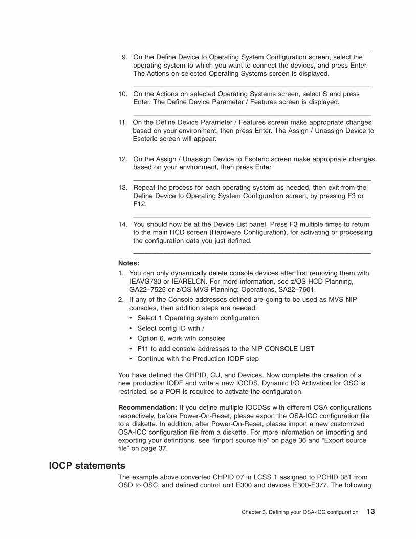
View port parametersThe View port parameters panel allows you to view Network Interface Cardstatistics. When enabled, it gives you statistical information and setting informationon your OSA-ICC. This panel is enabled after activating your server configuration.For multiple port definition, an option is provided to specify the port whoseparameters will be displayed.
Figure 8. View port parameters panels (1 of 2)
20 System z10 OSA-Express3 ICC Dual-Port Guide
Note: In order to see this panel, at least one port has to be configured; otherwise,the command fails with reject code A9. Appendix B, “Error codes that can bereturned for an Advanced Facilities Function,” on page 77 contains a list oferror codes that can be returned for an Advanced Facilities Function. Theseerrors pertain mainly to development and module communication, ensuringvalid SE interface interaction; however some error codes may beencountered by the user. For panels related to validation process, Chapter 7,“Error and warning messages,” on page 63 describes all the possible errorcodes.
Run port diagnosticsThe Run port diagnostics panel is used to run diagnostics. The purpose ofrunning these diagnostics is to check if everything is correct in the hardware.Running port diagnostics will stop all traffic on both physical ports on the CHPID.
Figure 9. View port parameters panels (2 of 2)
Chapter 4. Controlling and configuring an OSA-ICC 21

Physical port identifier: Identifies the port you want to run diagnostics on. Sincethere is only one port in OSA-ICC, the entry field default is 0. However, the desiredport can be selected by using the pull down menu.
Figure 10. Run port diagnostics panel
Figure 11. Run port diagnostics warning panel
22 System z10 OSA-Express3 ICC Dual-Port Guide

Set card modeThe Set card mode panel is used to set the speed and mode of the OSA-ICC.
Note: This panel does not show the way the card is currently set. It is not a displaycard mode panel. This panel shows options to set the card. See “View portparameters” on page 20 to see how the card is set.
Figure 12. Run port diagnostics panel
Chapter 4. Controlling and configuring an OSA-ICC 23

Physical port identifier: Since there are multiple ports, a selection is made tospecify which port speed to set. By default this field is set to zero.
Speed/Mode: The default is Auto Negotiate. If auto-negotiate fails, the default is100 Mb, half duplex. The speed/mode is changed dynamically, but it isrecommended that you do not make this change while sessions are active andconnected.
Display client connectionsThe Display client connections you to view currently connected clients. Thisinformation is queried at the time you open this panel. To refresh the information,exit the panel and reopen it.
Session Index specifies the session number. The valid range is from 1–120.
Figure 13. Set card mode panel
Figure 14. Display client connections panel
24 System z10 OSA-Express3 ICC Dual-Port Guide

Status specifies whether the session is not configured, available, connected, active,or definition error:
v Not configured: the session has not yet been configured.
v Available: the session has been configured and the client can connect to it.
v Connected: the session has been configured and the client is connected to it.
v DHD pending: the client has been disconnected. However, since DHD wasenabled, OSA-ICC has not notified the host operating system yet.
v Definition error: the session is not a valid session and the client cannot connect.The session CSS, MIFID, or Device Number does not exist or was dynamicallydeleted during dynamic I/O.
Physical Port Identifier displays which server port the client is connecting through.
MAC specifies the address of the client that is being connected if the client is onthe local end. Otherwise, the MAC address of the router is displayed.
Client’s IP specifies the IP address of the attached client.
Port specifies the port number of server which the client will connect through
Socket Numbers specifies the Local TCP socket number that uniquely defines theconnection. This parameter is only useful to the OSA-ICC PE.
LT Index specifies the index in the LT table. A valid range is from 1–120. Thisparameter is only useful to the OSA-ICC PE.
Connect rule can be IP only, LU only, IP & LU, unknown. For more information onconnection rules, see Chapter 2, “Dual-port connection rules,” on page 5.
Display active session configurationThe Display active session configuration panel is used to display the activesession configuration for a given OSC. This includes a list of the sessions that areconfigured for the OSC and configuration information about each session.
Session Index specifies the session number.
Figure 15. Display active session configuration panel
Chapter 4. Controlling and configuring an OSA-ICC 25

State specifies whether the session is not configured, available, or has a definitionerror:
v Not configured: the session has not yet been configured.
v Available: the session has been configured and the client can connect to it.
v Definition error: the session is not a valid session and the client cannot connect.The session CSS, MIFID, or Device Number does not exist or was dynamicallydeleted during dynamic I/O.
CSS specifies the logical channel subsystem ID. The valid range for CSS is 0–3.
MIFID is the logical partition MIF image ID. A valid range for the Image Id is 1–F.
Device Number is a number assigned for each device that was defined in theIOCDS.
LU Name defines a group or pool of devices that identifies what session you aregoing to connect to.
Client’s IP (optional) specifies the IP address that client will use to connect to thesession. The client’s IP address can remain 0.0.0.0 or empty in order to allow anyclient to connect to a specific session. If a non-zero IP is specified, any client with anon-matching IP is rejected.
IP Filter gives a range of client IP addresses that are allowed to connect through agiven physical port. This IP filter is only applicable when the client’s IP address isspecified.
Session Type can be console, operating system console, or printer.
DHD (Defer Host Disconnect) indicates the amount of time to wait (in seconds) untilOSA-ICC tells the host that the client session has disconnected.
RSP (Response Mode) indicates if response mode is enabled or disabled. Ifenabled, the host waits for the client to send an acknowledgement on the Telnetlevel for every packet that is transmitted. This enables the user to check for badLANs, poor performance, or other issues.
RTO (Response Time Out): specifies how long to wait (in seconds) for a responsefrom the client before performing a client disconnect. The default RTO is 60. Thevalid range for RTO is 1-300.
Notes:
1. The phrase Response Time Out and Read Time Out are synonymous forOSA-ICC
2. If no RTO is specified, the Missing Interrupt Handler (MIH) should be disabled.
3. If an RTO value is specified, MIH should be set to at least 50% greater than theRTO value. MIH is set via the operating system.
LOGO this feature has two values ENABLE/DISABLE. When enabled the three linelogo appears on client session, if disabled this three line logo will not appear. Formore information on the three line logo display, see Section 4.
26 System z10 OSA-Express3 ICC Dual-Port Guide

Display active server configurationThe Display active server configuration panel is used to display the activeTCP/IP connection configuration information about the physical port.
Server Name specifies the name of the server to which a client is connected.
Host IP Address specifies your IP address.
TCP Port specifies the port that the server will use to connect with the client.
Default Gateway specifies IP address gateway to any machines out of network.
Subnet Mask specifies a mask used to determine the subnet to which an IPaddress belongs.
Frame type specifies the Ethernet standards that you want the network to follow.Every host in a network must have the same frame type. It is stronglyrecommended that you use DIX as your frame type. SNAP refers to IEEE 802.2
Figure 16. Display active server configuration panel
Chapter 4. Controlling and configuring an OSA-ICC 27

framing, but most traffic on Ethernet is usually carried on DIX (802.3) frames.Please contact your network administrator to see what you are using.
MTU Size(B) specifies the maximum size to be transferred in one frame. A validrange is from 64–1492. A user would use an MTU size of less than 1492 when therouting equipment does not support anything above 576.
Panel configuration optionsThe Panel configuration options panel is the high level selection panel for theconfiguration options that are used for editing a session or server configuration,validating panel values, and/or viewing validate panel values errors. To choose apanel configuration option, select a utility option and click OK.
Edit session configurationThe Edit session configuration panel is used to edit the session configuration fora given OSC. This includes a list of the sessions that are configured for the OSCand configuration information about each session. The display is the same as theDisplay active session configuration panel except the fields may be edited.
Note: In order to make your edited session the active configuration, you mustvalidate then activate it. For more information about validating, and activatingsee “Validate panel values” on page 33 and “Activate configuration” on page49. In addition, you may want to export your source file as a backup. Formore information on exporting, see “Export source file” on page 37.
Figure 17. Panel configuration options panel
28 System z10 OSA-Express3 ICC Dual-Port Guide

Index specifies the session number.
State specifies whether the session is not configured, available, or has a definitionerror:
v Not configured: the session has not yet been configured.
v Available: the session has been configured and the client can connect to it.
v Definition error: the session is not a valid session and the client cannot connect.The session CSS, MIFID, or Device Number does not exist or was dynamicallydeleted during dynamic I/O.
CSS specifies the logical channel subsystem (LCSS) ID number. A valid range forCSS is 0–3.
MIFID is the logical partition MIF image ID. It specifies the logical partition within theLCSS with which the device will communicate. A valid range for the Image Id is 1–F.
Device Number is a number assigned for each device. A valid range for the devicenumber is 1-65535.
LU Name defines a group pool of devices. Identifies what session you are going toconnect to. This field is not case-sensitive.
Client’s IP (optional) specifies the IP address that client will use to connect to thesession. The client’s IP address can remain 0.0.0.0 or empty in order to allow anyclient to connect to a specific session.
IP Filter (optional) defines a range of IP addresses that can connect to the session.Clients IP addresses that match the range of the IP filter will be allowed to connect.Likewise clients with IP addresses outside the range of the IP_FILTER requesting toconnect will be refused a connection. The IP filter is applied to the Client’s IP in the
Figure 18. Edit session configuration panel
Chapter 4. Controlling and configuring an OSA-ICC 29

same manner in which a network subnet mask is applied to the host IP. This field isassigned the value 255.255.255.255 by default.
Session Type can be TN3270, operating system console, or printer. The default isthe operating system console.
DHD (Defer Host Disconnect): indicates the amount of time to wait (in seconds)until OSA-ICC tells the host that the client session has disconnected. For example,if you wanted to turn your PC off without the host knowing you left, you would clickon the radio button for ″enable with no timeout for deferment.″ This option specifiesthat the host will never be informed that you have logged off. A valid range for DHDis 1-86400 (24 hours in seconds).
RSP (Response Mode) indicates whether response mode is enabled or disabled. Ifenabled, the host waits for the client to send an acknowledgement on the Telnetlevel for every read, write, or packet it receives. This enables the user to check forbad LANs, poor performance, or other issues.
RTO (Response Time Out) specifies how long to wait (in seconds) for a responsefrom the client before performing a client disconnect. The default RTO is 60. Thevalid range for RTO is 1-300.
Notes:
1. The phrase Response Time Out and Read Time Out are synonymous forOSA-ICC
2. If no RTO is specified, Missing Interrupt Handler (MIH) should be disabled. If anRTO value is specified, MIH should be set to at least 50% greater than the RTOvalue. MIH is set via the operating system.
To edit a field:
1. Highlight the entry you want to edit
2. Double click the change button at the button of the screen
3. Make any desired changes. Be sure to scroll down to view all the fields that youcan edit. For a description of the fields, see the field descriptions above.
4. 4. Click OK to save the updated session information or the information will belost.
5. Validate and activate your changes. For more information on validating andactivating see, “Validate panel values” on page 33, and “Activate configuration”on page 49. In addition, you may want to export your configuration as backup.For more information on exporting, see “Export source file” on page 37.
30 System z10 OSA-Express3 ICC Dual-Port Guide

Edit server configurationThe Edit server configuration panel is used to edit the server configuration for agiven OSC. For this panel the option is given to configure a single port or both. Ifboth ports are configured and the user wishes to disable a given port the values forHost IP address, TCP port and Subnet Mask must be set to the default state (zero).At least one port must be defined at a given time in order for the server to beconfigured. An example of disabled Port 1 and enabled Port 0 is shown in Figure 20on page 32.
Figure 19. Edit session configuration panel
Chapter 4. Controlling and configuring an OSA-ICC 31
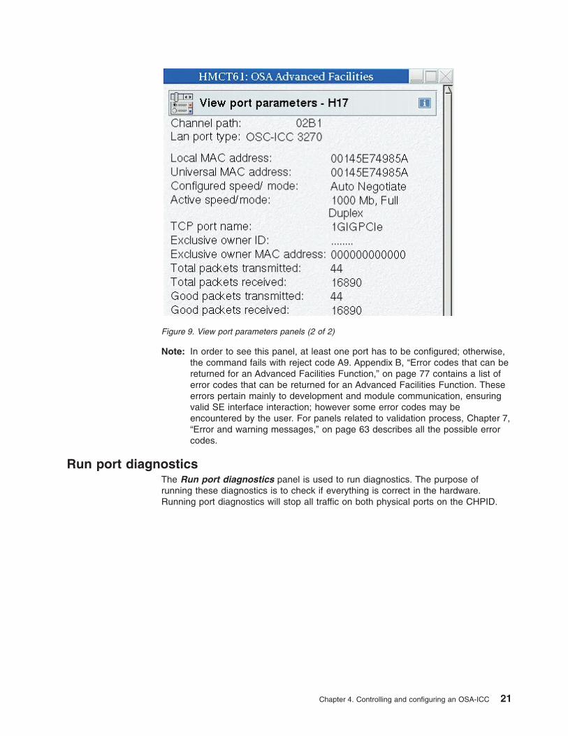
The Edit server configuration panel requires the following input:
Server name Used for display only.
Host IP Address specifies your IP address.
TCP Port Port that the server will use to connect with the client. A valid range is1–65536.
Default Gateway specifies the IP address, in dotted decimal format, of the defaultgateway (router) that will forward all traffic that is not destined to a local hostresiding on a network that one of the OSA-ICC ports is physically connected to.Only one Default Gateway can be specified for either single port, or multi-portdeployments.
The default gateway must not be blank; it must contain a dotted decimal IPaddress, otherwise a panel error will be flagged. Note that 0.0.0.0 is allowed as avalid input.
Figure 20. Edit server configuration panel
32 System z10 OSA-Express3 ICC Dual-Port Guide

Note that the IP address you specify is not checked as part of the configurationvalidation operation to determine if the respective router is reachable via eitherOSA-ICC port. Therefore, you must ensure that the host at the respective addressis not only reachable through one of the OSA-ICC ports, but that it will also satisfyyour IP routing requirements.
Subnet Mask determines what subnet an IP address belongs to.
Frame type specifies the Ethernet standards that you want the network to follow.Every host in a network must have the same frame type. It is stronglyrecommended that you use DIX as your frame type. SNAP refers to IEEE 802.3framing, but most traffic on Ethernet is usually carried on DIX frames. Pleasecontact your network administrator to see what you are using.
MTU Size(B) specifies the maximum size to be transferred in one frame. A validrange is from 256–1492. The default is 1492. Speak to your network administratorto see if you need the MTU size to be different from the default.
Validate panel valuesThe Validate panel values panel is used to validate any values entered in theconfiguration panels.
Notes:
1. In order to make your validated session the active configuration, you mustactivate it. For more information about activating see “Activate configuration” onpage 49. In addition, you may want to export your source file as a backup. Formore information on exporting, see “Export source file” on page 37.
2. 2. For a list of errors and warnings that you might receive after validating, seeChapter 7, “Error and warning messages,” on page 63.
If you receive errors during your validation, you must fix them before you canactivate the configuration. If you receive warnings during your validation, you maystill activate your configuration. However, it is suggested that you address thesewarnings and re-validate before you activate your configuration.
Display validate panel errorsThe Display validate panel errors panel is used to view any errors you might havereceived while validating. For a list of errors and warnings that you might receive,
Figure 21. Validate panel values panel
Chapter 4. Controlling and configuring an OSA-ICC 33

see Chapter 7, “Error and warning messages,” on page 63.
Configuring via manual editingConfiguring your OSA-ICC results in the creation of a session configuration file. Youcan create this file by entering data via panel entry or by manually editing the file.Panel entry requires that you move through a series of data entry panel and enterconfiguration data on those panels. Your other option is to edit your configurationmanually using your favorite workstation editor. Manual editing is much faster formultiple data entries because of the powerful editing capabilities of most workstationeditors.
You can edit the configuration file on your Hardware Management Console or SEconsole or you can export the configuration file to a diskette, edit it on theworkstation of your choice, and import back to the SE. You can also edit theconfiguration file directly on the SE console by selecting the Edit source file panelunder the Manual configurations options panel. The configuration file is namedIQZCxxxx.trm (xxxx is the PCHID number where the 1000Base-T port is located)and is referred to as the ’source’ file on the related panels.
Before you begin: In order to perform a manual operation on your configuration fileyou must use the panels on the SE to get to the OSC manual configuration panel.For details about how to get to the card specific Advanced facilities panel, see“Steps for accessing the Advanced Facilities panel” on page 16.
1. From the Advanced facilities panel select OSC manual configuration.You willsee the OSC manual configuration panel.
Figure 22. Display validate panel errors panel
34 System z10 OSA-Express3 ICC Dual-Port Guide

2. Export source file (optional). For more information about exporting source files,see “Export source file” on page 37.
3. Edit source file. For more information about editing source files, see “Editsource file” on page 40.
4. Import source file (optional). For more information about importing source files,see “Import source file” on page 36.
5. Validate source file. For more information about validating source files, see“Validate source file” on page 48.
6. Activate configuration. For more information about activating a configuration,see “Activate configuration” on page 49.
Manual configurations optionsThe Manual configurations options panel is the high level selection panel for themanual configuration options that are used for importing a source file, exporting asource file, editing a source file, and validating a source file. Manual configuration isthe most efficient way to create a configuration file because it allows you to createand modify a configuration file with the editor of your choice. Many editors allow youto copy and paste sections of the file and to find and replace data items quickly andeasily.
The dual-port configuration file has new components that allow the validation of thedefined physical ports. When configuring through the manual option, thesecomponents will, by default, appear in the file. If only one physical port will bedefined, the default data of the other physical port must be removed in order for thevalidation process to be successful.
To choose a manual configuration option, select a utility option and click OK.
Figure 23. OSC manual configuration panel
Chapter 4. Controlling and configuring an OSA-ICC 35

Import source fileAny exported configuration file that has been modified must be imported before thechanges can be applied. Here are the steps for importing a session configurationfile from a USB flash drive or other supported device.
Note: In order to make the imported source file the active configuration, you mustedit the source file (optional), validate the source file and then activate it. Formore information about editing, validating, and activating source files see,“Edit source file” on page 40, “Validate source file” on page 48 and “Activateconfiguration” on page 49. In additon, you may want to export your sourcefile as a backup. For more information on exporting, see “Export source file”on page 37.
Steps for importing a configuration file: Before you begin: You must be awareof the naming requirements for a configuration file. These requirements are that thefilename has a maximum of eight characters.
1. Insert USB flash drive or other supported device containing the source file intoyour USB flash drive or other supported device. If you are working from the SE,your import will be from the SE. If you are working from the HardwareManagement Console, the import will be from the Hardware ManagementConsole. If your Hardware Management Console is in single object operation,you must insert the USB flash drive or other supported device in the SE
2. From the Manual configuration options panel select Import source file . TheImport source file panel appears with a list of all the files on the disk.
For example:
Figure 24. Manual configuration panel
36 System z10 OSA-Express3 ICC Dual-Port Guide

3. Highlight the file you would like to import and click OK. The file you specifiedwill be imported.
Warning: Although you can import any file listed, trying to validate and activatea file that is not a configuration file will fail.
4. 4. Edit (optional), validate your imported source file, and activate theconfiguration.
For an example of a source file, see “Example of a correct configuration file” onpage 41.
Export source fileThe Export source file panel is used to export a session configuration file to aUSB flash drive or other supported device so you can edit the configuration file withyour editor. You can also use this panel to export your configuration options as abackup. Here are the steps for exporting the session configuration file to a USBflash drive or other supported device.
Steps for exporting a configuration file: Before you begin: You must be awareof the naming requirements for a configuration file. These requirements are that thefilename has a maximum of eight characters.
1. Insert USB flash drive or other supported device containing the source file intoyour USB flash drive or other supported device. If you are working from the SE,your import will be from the SE. If you are working from the HardwareManagement Console, the import will be from the Hardware ManagementConsole. If your Hardware Management Console is in single object operation,you must insert the USB flash drive or other supported device in the SE.
2. From the Manual configuration options panel select Export source file. TheExport source file will appear.
For example:
Figure 25. Import source file panel
Chapter 4. Controlling and configuring an OSA-ICC 37

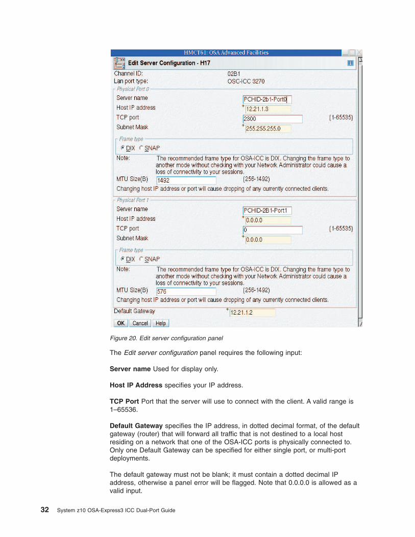
3. Type in the name to be given to the exported configuration file in the Exportsource file name field and click OK. The panel is going to export theconfiguration file for the PCHID selected.
Import source file via FTPIf you exported a configuration file for editing you must import it in order to use it.Here are the steps for importing a session configuration file via FTP.
Note: In order to make the imported source file the active configuration, you mustedit the source file (optional), validate the source file and then activate it. Formore information about editing, validating, and activating source files see“Edit source file” on page 40, “Validate source file” on page 48 and “Activateconfiguration” on page 49. In addition, if you update the file you may want toexport your source file as a backup. For more information on exporting, see“Export source file via FTP” on page 39.
Steps for importing a configuration file via FTP: Before you begin: You mustbe aware of the naming requirements for a configuration file. These requirementsare that the filename has a maximum of eight characters.
1. From the Manual configuration options panel select Import source file viaFTP. The Import source file via FTP will appear.
For example:
Figure 26. Export source file panel
38 System z10 OSA-Express3 ICC Dual-Port Guide

2. Enter the IP address, user identification, password, and fully qualified file nameand click OK. The file you specified will be imported.
Warning: Although you can import any file listed, trying to validate and activatea file that is not a configuration file will fail.
3. Edit (optional), validate your imported source file, and activate the configuration.For an example of a source file, see “Example of a correct configuration file” onpage 41.
Export source file via FTPThe Export source file via FTP panel is used to export a session configuration filevia FTP so you can edit the configuration file with your editor. You can also use thispanel to export your configuration options as a backup. Here are the steps forexporting the session configuration file via FTP and editing it on your workstation ofchoice.
Steps for exporting a configuration file via FTP: Before you begin: You mustbe aware of the naming requirements for a configuration file. These requirementsare that the filename has a maximum of eight characters.
1. From the Manual configuration options panel select Export source file viaFTP. The Export source file via FTP will appear.
For example:
Figure 27. Import source file via FTP panel
Chapter 4. Controlling and configuring an OSA-ICC 39
2. Type in the IP address, user identification, password, and fully qualified filename to be given to the exported configuration file and click OK. The panel isgoing to export the configuration file for the PCHID selected.
Edit source fileIf you have exported your configuration file, you can use a workstation editor ofyour choice. Otherwise you can edit the file from the Edit source file panel. Hereare the steps for editing a configuration file via the Edit source file panel.
Note: In order to make the edited source file the active configuration, you mustimport the source file (only if you are using a workstation editor and not theedit source file panel), validate the source file, and then activate it. For moreinformation about exporting, validating, and activating source files see,“Import source file” on page 36, “Validate source file” on page 48 and“Activate configuration” on page 49.
Steps for editing a source file:
1. From the OSC manual configuration panel select Edit source file. Yoursource file will be displayed.
2. Make any necessary changes and save. For an example of a source file see,“Example of a correct configuration file” on page 41.
3. Validate your source file to check for any errors. If the file did not validate errorfree, the errors messages will appear directly in your source file. For anexample of a source file with errors in it see, “Example of a configuration filewith a warning” on page 42.
Sections of the configuration fileThere are two sections to the session configuration file:
1. The first section is called the server section and includes parameters about theOSC as they relate to the OSA-Express card. In the file, the first line of theserver section is the <OSC_SERVER> tag and the last line of the cardparameters is the </OSC_SERVER> tag.
Within the <OSC_SERVER> section of the file are the new dual-port physicalport configuration parameters. Each set of port parameters begin with the
Figure 28. Export source file via FTP panel
40 System z10 OSA-Express3 ICC Dual-Port Guide

<OSC_PHYSICAL_PORT> tag and ends with the </OSC_PHYSICAL_PORT>The index x is the index identifier of the physical port (0 or 1).
2. The second section includes parameters about the TN3270E sessions you wantto configure for your OSA-ICC. You can configure up to 120 sessions on anOSA-ICC. In the file, the first line of the session parameters is the<CONFIG_SESSION> tag and the last line of the card parameters is the</CONFIG_SESSION> tag.
Within the <CONFIG_SESSION> section of the file are the individual sessionconfiguration parameters. Each set session parameters begins with the<SESSIONx> tag and ends with the </SESSIONx> tag where x is the indexnumber of the TN3270 session within the configuration. In addition to theprevious session definition tags, the dual-port defined sessions contain a newIP_FILTER tag.
Example of a correct configuration file: The following is an example of aconfiguration file that matches the IOCP example given in this document.<OSC_SERVER><OSC_PHYSICAL_PORT0>
HOST_IP= 12.21.1.203PORT= 1500ETHERNET_FRAME= DIXMTU= 1492NAME= OSC_PORT_0
</OSC_PHYSICAL_PORT0>
<OSC_PHYSICAL_PORT1>HOST_IP= 12.21.1.204SUBNET_MASK= 255.255.255.0PORT= 1509ETHERNET_FRAME= DIXMTU= 1492NAME= OSC_PORT_1
</OSC_PHYSICAL_PORT1>
DEFAULT_GATEWAY= 12.21.1.2</OSC_SERVER>
<CONFIG_SESSION><SESSION1>
CSS= 03 IID= 02 DEVICE= 5400GROUP= “sess01"CONSOLE_TYPE= 1 RESPONSE= ON READ_TIMEOUT= 300DEFER_HOST_DISCONNECT= 86400CLIENT_IP= 12.21.1.25IP_FILTER= 255.255.248.0
</SESSION1>
<SESSION2>CSS= 00 IID= 01 DEVICE= 5401GROUP= "sess02"CONSOLE_TYPE= 1 RESPONSE= ON READ_TIMEOUT= 60
</SESSION2>
<SESSION3>CSS= 00 IID= 01 DEVICE= 5402GROUP= "sess03"CONSOLE_TYPE= 1 RESPONSE= ON READ_TIMEOUT= 60
</SESSION3></CONFIG_SESSION>
Chapter 4. Controlling and configuring an OSA-ICC 41

Example of a configuration file with a warning: The following is an example ofa configuration file that matches the configuration shown in the panels. Theconfiguration file also includes a sample warning message that you would see aftervalidating a file and receiving a warning.<OSC_SERVER>
<OSC_PHYSICAL_PORT1>HOST_IP= 12.21.1.204SUBNET_MASK= 255.255.255.0PORT= 1509ETHERNET_FRAME= DIXMTU= 1492NAME= PortDefinition1
</OSC_PHYSICAL_PORT1>
DEFAULT_GATEWAY= 12.21.1.2</OSC_SERVER>
<CONFIG_SESSION><SESSION1>// @@@ warning: This session is in Definition Error state
CSS= 03 IID= 02 DEVICE= F400GROUP= "sess01"CONSOLE_TYPE= 1 RESPONSE= ON READ_TIMEOUT= 300DEFER_HOST_DISCONNECT= 86400CLIENT_IP= 12.21.1.25IP_FILTER= 255.255.248.0
</SESSION1>
<SESSION2>CSS= 00 IID= 01 DEVICE= 5401GROUP= "sess02"CONSOLE_TYPE= 1 RESPONSE= ON READ_TIMEOUT= 60
</SESSION2></CONFIG_SESSION>
Configuration file syntaxThe manual configuration file syntax includes the server and client tag identifiersand their corresponding values. These tags define the same parameters as thePanel Entry input fields, although tag syntax may be slightly different from paneldefined names. For example, ETHERNET_FRAME= defines the same parameteras Frame type in the panel. The format of the manual configuration file is as shownin “An example of a correct configuration file” in the previous page. The followinggeneral rules apply to tag placement:
1. Tags that are immediately followed by an equal sign (=) need associated values.
2. Non-delimiter tags may be abbreviated to a minimum of four characters.
3. Tags can be placed in any order given that they are within the bounds of theirdelimiters.
4. Server tags must be within the server delimiters.
5. Session tags must be within the Inner Session Delimiter and these innerdelimiters must be within the Session Definition Delimiters.
The following is a list of the tags, delimiters and their descriptions.
Server tag identifiers
//
<OSC_SERVER> Server definition start delimiter
</OSC_SERVER> Server definition end delimiter
42 System z10 OSA-Express3 ICC Dual-Port Guide

Server tag identifiers
<OSC_PHYSICAL_PORT#> New physical port definition start delimiter
</OSC_PHYSICAL_PORT#> New physical port definition end delimiter
HOST_IP=
PORT=
DEFAULT_GATEWAY=
SUBNET_MASK=
ETHERNET_FRAME=
NAME=
MTU=
Client tag identifiers
<CONFIG_SESSION> Session definition start delimiter
</CONFIG_SESSION> Session definition end delimiter
<SESSION#> Inner session definition start delimiter
</SESSION#> Inner session definition end delimiter
CSS=
MIFID= or IID=
GROUP=
CLIENT_IP=
IP_FILTER=
CONSOLE_TYPE=
DEFER_HOST_DISCONNECT=
RESPONSE=
READ_TIMEOUT=
Server tag identifier descriptions
// Indicates that any text at the end of the line is treatedas a comment.
Note: Any user-entered comment is erased during activation.
Server tag identifier descriptions:
// This indicates that any text at the end of the line is treated as a comment.
Note: Any user-entered comment is erased during activation.
<OSC_SERVER>This tag indicates the beginning of the server configuration data. There canbe only one such tag in the configuration file. It must be followed by the</OSC_SERVER> tag, or a syntax error is produced.
</OSC_SERVER>This tag is the delimiter for the server configuration section. There can beonly one such tag in the configuration file. It must be preceded by the<OSC_SERVER> tag, or a syntax error is produced.
<OSC_PHYSICAL_PORTx>Marks the beginning of the individual physical port configuration; it must befollowed by the </OSC_PHYSICAL_PORTx> tag. Everything between the
Chapter 4. Controlling and configuring an OSA-ICC 43

<OSC_PHYSICAL_PORTx> and </OSC_PHYSICAL_PORTx> tags istreated as configuration data for one physical server port to which the clientcan connect. # is replaced by the corresponding index of the physical portvalue of 0 or 1. Each number can be used only once, since a physical portcan be configured only once.
</OSC_PHYSICAL_PORTx>Marks the ending of the individual physical port configuration; it must bepreceded by the <OSC_PHYSICAL_PORTx> tag. Physical port tags withinthis boundary beginning with <OSC_PHYSICAL_PORTx> and ending with</OSC_PHYSICAL_PORTx> can be defined in any order. Each tag canappear only once for a particular physical port. They are followed by anumber or string, which is assigned to a particular physical port parameter.
HOST_IP=This tag is used to label the Host’s IP address; a value that follows it shouldbe an IP address in dotted format (for example, 10.10.12.43). This addressis assigned to the OSA3270 server, and this is the address that TN3270Eclients will be connecting to. The following is an example of using this tag:HOST_IP= 10.10.121.44. This tag is required for configuration and there isno default value.
PORT=The port number on which the OSA3270 server will be listening (accepting)clients. For example, PORT= 3271. It is acceptable to use any valid portnumber in the integer range 1 to 65535. This is a required tag for serverconfiguration.
DEFAULT_GATEWAY=This value is used to specify the IP address, in dotted decimal format, ofthe default gateway (router) that will forward all traffic that is not destined toa local host residing on a network that one of the OSA-ICC ports isphysically connected to. Only one Default Gateway can be specified foreither single port, or dual-port deployments.
The DEFAULT_GATEWAY= tag is not required, if this tag is missing fromthe configuration file, the configuration validation will be successful and adefault gateway value of 0.0.0.0 will be set. However, if theDEFAULT_GATEWAY= tag is present in the configuration file, then it mustcontain a dotted decimal IP address. If no IP address is present, then avalidation syntax error will result
Please note that the IP address you specify will not be checked as part ofthe configuration validation operation to determine if the respective router isreachable via either OSA-ICC port. Therefore, you must ensure that thehost at the respective address is not only reachable via one of theOSA-ICC ports, but that it will also satisfy your IP routing requirements.
The DEFAULT_GATEWAY= tag is the only server tag that is not included inthe OSC_PHYSICAL_PORT boundary tags. Only one gateway is specifiedfor both physical ports. The gateway tag must be within the OSC_SERVERboundary tag.
SUBNET_MASK=The IP address in dotted decimal format for subnet mask. For example,SUBNET_MASK= 225.225.225.0. There is no default value; however it isan optional tag that will produce a warning if it is absent from theconfiguration file.
44 System z10 OSA-Express3 ICC Dual-Port Guide

ETHERNET_FRAME=Specifies the Ethernet standard that the network is defined to follow. Everyhost in a network must have the same frame type. The value can be DIX orSNAP.
This is a required tag for configuration it is defaulted to Default value:ETHERNET_FRAME= DIX
NAME=The name can be up to 15 characters and is not case sensitive. Acceptableinput characters include ASCII characters in the range given in Figure 29.This tag is required for configuration and there is no default value.
MTU=Specifies the maximum size to be transferred in one frame. A valid range isfrom 256–1492. A user would use an MTU size of less than 1492 when therouting equipment does not support anything above 576. This is a requiredtag for configuration. By default MTU is set to 1492.
Client tag identifier descriptions:
<CONFIG_SESSION>Marks the beginning of the session configuration.
</CONFIG_SESSION>Marks the end of the session configuration.
Figure 29. Valid characters for NAME= tag
Chapter 4. Controlling and configuring an OSA-ICC 45

<SESSION#>Marks the beginning of the individual session configuration; it must befollowed by the </SESSION#> tag. Everything between the <SESSION#>and </SESSION#> tags is treated as configuration data for one session. #is replaced by the corresponding index of the session. This number is in therange 1-120. Each number can be used only once, since a session can beconfigured only once.
</SESSION#>Marks the ending of the individual session configuration; it must bepreceded by the <SESSION#> tag. Client tags (tags following thisdefinition) within this boundary beginning with <SESSION#> and endingwith </SESSION#> can be defined in any order. Each tag can appear onlyonce for a particular session. They are followed by a number or string,which is assigned to a particular session’s parameter.
CSS= The channel subsystem number. The valid range is 0-3. This number iscompared with IOCDS to make sure that it is defined. This tag is requiredfor configuration and there is no default value.
MIFID= or IID=The image ID for the session. The valid range is 1-F. This number iscompared with IOCDS to make sure that it is defined. This tag is requiredfor configuration and there is no default value.
DEVICE=This is the device number associated to the session. This hexadecimalnumber will be compared with IOCDS to make sure that it is defined. Thevalid range is 1-65535. This tag is required for configuration and there is nodefault value.
GROUP=Any valid ASCII characters except double quotes. The name must beincluded in double quotes. Acceptable input characters include ASCII valuesin the range displayed in Figure 30 on page 47. This tag is required forconfiguration and there is no default value.
46 System z10 OSA-Express3 ICC Dual-Port Guide

CLIENT_IP=This is the IP address that the client will use to connect to this session.CLIENT_IP should be in a dotted decimal format, for example, 10.10.23.23;specifying a CLIENT_IP is optional. Omitting this tag however will allow anyclient to connect to a specific session. This tag is required for configurationand there is no default value.
CONSOLE_TYPE=Specifies the session type: 1 (TN3270), 2 (master system operator console)or 3 (printer). The default configuration file should contain numberdescriptions in the comments next to the line with this tag. This is arequired tag for configuration it is defaulted to: CONSOLE_TYPE= 1.
DEFER_HOST_DISCONNECT=Indicates the amount of time to wait (in seconds) until the session tells thehost you have disconnected. For example, if you wanted to turn your PC offwithout the host knowing you left, you would specify a value of 0. Then,DEFER_HOST_DISCONNECT will be enabled, but timeout for defermentwill be infinity. The host will never be informed that you have logged off. Forexample, DEFER_HOST_DISCONNECT =0 If this tag is not used, thenDefer Host Disconnect will be disabled for particular session. If value isspecified, then it will be used as a deferment timeout parameter. Forexample, DEFER_HOST_DISCONNECT= 120 the valid range for thisparameter is 1-86400. This tag is optional for file configuration, by defaultthere is no DHD.
Figure 30. Valid characters for GROUP= tag
Chapter 4. Controlling and configuring an OSA-ICC 47

RESPONSE=Response mode can be ON or OFF; that is, enabled or disabled. This tag isoptional in file configuration, by default it is OFF. Recommended selection isON.
READ_TIMEOUT=Read timeout (RTO) is defaulted to 60 seconds, but if the user wishes tocustomize this parameter, they can do so by assigning number n to readtimeout, as in READ_TIMEOUT= n. The valid range for n is 1-300 seconds.This tag is optional in file configuration.
Note: If no RTO is specified, Missing Interrupt Handler (MIH) should bedisabled. If an RTO value is specified MIH should be set to at least50% greater than the RTO value. MIH is set via the operatingsystem.
IP_FILTER=The IP_FILTER tag is similar to the network subnet mask; it defines a rangeof IP addresses that can connect to a given session. Clients requesting toconnect that fit within the range of the IP_FILTER will be allowed toconnect. Likewise clients with IP addresses outside this range requesting toconnect will be refused a connection. The IP_FILTER is only applicable ifthe CLIENT_IP tag is specified. By default this tag is assigned the value255.255.255.255, this is equivalent to specifying a unique client IP to thesession definition.
Validate source fileOnce you have edited a configuration file you must validate it in order to ensurethat the file is valid before activating it. Here are the steps for validating aconfiguration file.
Warning: In order to make the validated source file the active configuration, youmust activate it. Activating a configuration makes any changes you made effectiveimmediately. This could result in active sessions being dropped. For moreinformation about activating source files see “Activate configuration” on page 49.
Validating a manual configuration file1. From the OSC manual configuration panel select Validate source file .
2. If the source file you are validating has errors or warnings, they will be includedin comments in the source file. Only the first error will be detected. Therefore,you must fix that error and validate the source file again to determine if thereare any additional errors. For an example of a source file with warnings in it,see “Example of a configuration file with a warning” on page 42. For a list oferrors that you might receive, see Chapter 7, “Error and warning messages,” onpage 63. Here is the panel you will see if your source file has errors:
48 System z10 OSA-Express3 ICC Dual-Port Guide
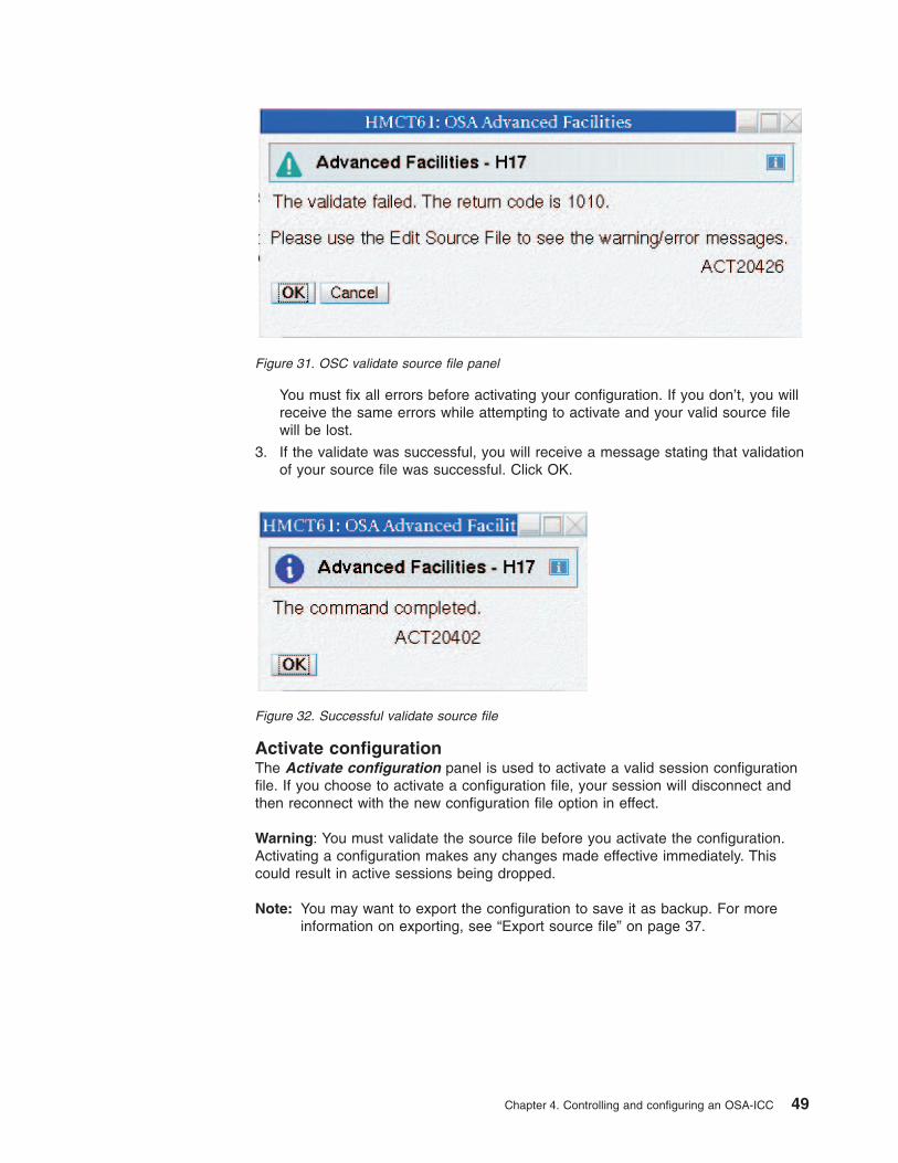
You must fix all errors before activating your configuration. If you don’t, you willreceive the same errors while attempting to activate and your valid source filewill be lost.
3. If the validate was successful, you will receive a message stating that validationof your source file was successful. Click OK.
Activate configurationThe Activate configuration panel is used to activate a valid session configurationfile. If you choose to activate a configuration file, your session will disconnect andthen reconnect with the new configuration file option in effect.
Warning: You must validate the source file before you activate the configuration.Activating a configuration makes any changes made effective immediately. Thiscould result in active sessions being dropped.
Note: You may want to export the configuration to save it as backup. For moreinformation on exporting, see “Export source file” on page 37.
Figure 31. OSC validate source file panel
Figure 32. Successful validate source file
Chapter 4. Controlling and configuring an OSA-ICC 49

Display activate configuration errorsThe Display activate configuration errors panel is used to view the file whichcontains configuration error messages if any exist. If a configuration validatedsuccessfully, there are no activate configuration errors.
For a list of possible errors and warnings, see Chapter 7, “Error and warningmessages,” on page 63.
Debug utilitiesThe Debug utilities panel is the high level selection panel for the debug utilitiesthat are used for debugging a problem with a session on an OSC.
To choose an OSC debug utility option, select a utility option and click OK.
Figure 33. Activate configuration panel
Figure 34. Display activate configuration errors panel
50 System z10 OSA-Express3 ICC Dual-Port Guide

Ping UtilityThe Ping Utility panel is used to ping an active session to verify the status of theconnection. A user can also ping the server’s own IP address to verify the server’sconnection.
The Ping utility requires the following input:
v Client’s IP address: Specifies the IP address of the device you want to ping
v Length: You can select the default length of 256 bytes or enter a custom lengthof between 8 and 3200 bytes
Figure 35. Debug utilities panel
Figure 36. Ping Utility
Chapter 4. Controlling and configuring an OSA-ICC 51

v Count: You can select the default count of 1 or enter a custom count of between1 and 10
v Timeout: You can select the default timeout value of 10 seconds or enter acustom timeout value.
Trace route utilityThe Trace route utility panel is used to trace the route to the client interfacespecified by the IP address. The results of the trace route will give you every hopfrom OSA-ICC to the interface specified by the client’s IP address.
The trace route utility requires the following input:
v Client’s IP address: The IP address of the device you want to ping
v Max TTL: You can select the default maximum of 30 or enter a custom value ofbetween 1 and 255
v Attempts: You can select the default number of attempts of 3 or enter a customnumber of between 1 and 20
v Port: You can select the default port of 4096 or enter a custom port value ofbetween 2048 and 60000
v Wait time in seconds: Specifies how long to wait for a trace route operation tocomplete.
Figure 37. Trace route utility
52 System z10 OSA-Express3 ICC Dual-Port Guide

v Extra Debug messages: If you select yes, extra debug messages are included inthe result of the trace route.
Drop sessionThe Drop session panel is used to drop a session from an OSA-ICC. You can usethis panel if you need to drop a session because you can’t get to a PC or you havea bad connection.
If you selected auto-reconnect during the customization of your PCOMM session,drop session will not work. The auto-reconnect option will automatically reconnectyour session after you drop it.
The drop utility requires a session index number to identify which session to drop.
The drop session panel requires the following input:
v Session index: The index from the session table.
Logo ControlsThe Logo Controls panel is used to enable or disable the 3 line logo (see page56) that appears when the client console session is connected before traffic beginsto flow.
Figure 38. Drop session utility
Chapter 4. Controlling and configuring an OSA-ICC 53

The logo controls utility requires a session index from the session table number toidentify which session’s logo will be enabled or disabled.
The drop session panel requires the following input:
v Session index: The index from the session table.
v Button selection to Enable Logo or Disable Log
Query commandThe Query Command utility panel is used as an informational query commandinterface to the OSA-ICC microcode. Information useful for troubleshooting can bequeried via this function.
The query command utility requires an input command. Some commands mayrequire additional input parameters. Enter help to view a list of currently supportedcommands. A supported command is further explained by entering help then thecommand name; an example is help arp. Some of the supported commands arearp and route. The results of a query command are displayed on a panel aftersuccessful execution of that command.
Cancel commandThe Cancel Command utility panel allows you to cancel a command that isexecuting on an OSC.
Figure 39. Logo Controls
Figure 40. Query command
54 System z10 OSA-Express3 ICC Dual-Port Guide

Figure 41. Cancel command panel
Chapter 4. Controlling and configuring an OSA-ICC 55

56 System z10 OSA-Express3 ICC Dual-Port Guide

Chapter 5. OSA-ICC programming considerations
3270 Client SupportThe OSA-ICC only supports TCP/IP RFC 2355 compliant Telnet TN3270E emulatorprograms, such as IBM eNetwork Personal Communications. These clients appearto the z/OS Operating System as non-SNA, DFT terminals. It does not supportCOAX attached clients. The OSA-ICC is essentially a control unit on a port of anOSA 1000BaseT Ethernet cards which controls up to 120 devices. In this documentan OSA-ICC is referred to an OSC CHPID and each OSC can provide consolesupport for any logical partition in any CSS on your z890 or z990 processor. TheOSA-ICC configuration panels allow you to specify which logical partition on yourprocessor each device is attached to using the CSS ID, MIF image ID, and devicenumber.
The 3174 supports both COAX and LAN-attached, SNA and non-SNA, CUT andDFT mode terminals. It does not support TCP/IP attached clients. When configuredin non-SNA, DFT mode, the 3174’s 32 devices must all be assigned to a singlelogical partition on one specific S/390 or zSeries processor.
© Copyright IBM Corp. 2009 57

58 System z10 OSA-Express3 ICC Dual-Port Guide

Chapter 6. eNetwork Personal Communications Configuration
Below is an example of defining a PCOMM 3270 session. The example usesPCOMM version 5.6 for Windows. If you are using a different version, your panelsmay look slightly different.
Steps for customizing a PCOMM session1. To Define an Ethernet attached session to the host, click on ’Link Parameters.’
_______________________________________________________________
2. Define the connection from the workstation to the OSA-ICC server.
Figure 42. Customize communication screen
© Copyright IBM Corp. 2009 59

Enter the Host name or IP Address. The values in Host Name or IP Addressand Port Number were specified when defining the OSA-ICC serverconfiguration. For more information on defining your OSA-ICC serverConfiguration see, “Edit server configuration” on page 31.
_______________________________________________________________
3. Enter the LU or Pool Name. The value in LU or Pool Name was specified whendefining the group name in the session configuration.
_______________________________________________________________
4. Enter the Port Number.
_______________________________________________________________
5. Click OK on the Telnet3270 panel.
Note: It is recommended that you select auto-reconnect. However, understandthat the drop session option for configuring an OSA-ICC will not work.The auto-reconnect option will automatically reconnect your sessionafter you drop it. For more information on the drop session option, see“Drop session” on page 53.
_______________________________________________________________
Figure 43. Telnet3270 screen
60 System z10 OSA-Express3 ICC Dual-Port Guide

If you wish, use the Session Parameters option in Customize Communication to seta screen size other than 24 by 80. It is recommended that your screen sizematches the operating system screen size.
Clicking OK on the Customize Configuration panel causes PCOMM to initiate theconnection to the host.
If the host session is not ready for communication, the screen displayed shows yourconnection information for this session. For example:
Line 1: OSAE000 is the defined server name; 13.21.1.3:3000 shows the definedserver address and port number.
Line 2: session index; LCSS number; LPAR number (this is NOT the MIF image IDwe specified for the session, but it is related); logical CU number (always 0); unitaddress for this device; LU name.
Line 3: information for the connected processor.
When using IBM eNetwork Personal Communications (PCOMM) for client TN3270Edisplay sessions, the following statement must be present in the PCOMM profilefiles (xxx.WS) to ensure that printer WCC controls are ignored if sent by the host:[LT]
IgnoreWCCStartPrint=Y
If this statement is not present in your PCOMM profile files you will have to edit thexxx.WS files on your client PC with a PC text editor to add the statement lines.
Figure 44. E - Capture — [24x80]
Chapter 6. eNetwork Personal Communications Configuration 61

62 System z10 OSA-Express3 ICC Dual-Port Guide

Chapter 7. Error and warning messages
By validating your configuration file, either by the Validate panel values panel orthe Validate Source File panel, you are checking for any errors in yourconfiguration. Any errors or warning you receive can be viewed in either theDisplay Validate panel values panel or in the source file as comments. Table 2 isa list of errors and warnings that you could receive:
Table 2. Errors from validate source file
Code Text
1010 // @@@ error: Sessions X and Y aredefining same device; i.e. samecss/mifid/device
1020 // @@@ error: Can’t have multiple<OSC_SERVER> tags
1021 // @@@ error: Can’t have <OCS_SERVER>tag within session configuration
1022 // @@@ error: Card configuration alreadydone
1030 // @@@ error: Illegal </OSC_SERVER>position
1031 // @@@ error: Server configuration sectionhas to be closed by </OSC_SERVER>
1032 // @@@ error: Missing HOST_IP tag
1033 // @@@ error: Missing PORT tag
1034 // @@@ error: MissingDEFAULT_GATEWAY tag
1035 // @@@ error: Missing SUBNET_MASK tag
1036 // @@@ error: Missing ETHERNET tag
1037 // @@@ error: Missing NAME tag
1038 // @@@ error: Missing MTU tag
1039 // @@@ error: Can’t have multiple HOST_IPtags
1040 // @@@ error: No host IP value
1041 // @@@ error: Can’t have host IP outside ofcard configuration area
1042 // @@@ error: Host IP value is in bad format
1043 // @@@ error: Have to define host IPbetween <OSC_PHYSICAL_PORT#> and</OSC_PHYSICAL_PORT#> tags
1044 // @@@ error: Host name value is too long -15 char is Max.
1045 // @@@ error: No host name value
1046 // @@@ error: Unsupported name format
1047 // @@@ error: Can’t have name outside ofcard configuration area
1048 // @@@ error: Can’t have multiple NAMEtags
© Copyright IBM Corp. 2009 63

Table 2. Errors from validate source file (continued)
1049 // @@@ error: Have to define host namebetween <OSC_PHYSICAL_PORT#> and</OSC_PHYSICAL_PORT#> tags
1050 // @@@ error: No host port value
1051 // @@@ error: Can’t have host port outsideof card configuration area
1052 // @@@ error: Out of range port value
1053 // @@@ error: Can’t have multiple PORTtags
1054 // @@@ error: Have to define host portbetween <OSC_PHYSICAL_PORT#> and</OSC_PHYSICAL_PORT#> tags
1055 // @@@ error: Host port value used forprevious physical port definition
1056 // @@@ error: Host IP value used forprevious physical port definition
1057 // @@@ error: Host IP for Physical Port 0and Physical Port 1 are defined in the samesegment
1060 // @@@ error: No gateway router value
1061 // @@@ error: Can’t define gateway outsideof the card configuration area
1062 // @@@ error: Invalid gateway addressvalue or format
1063 // @@@ error: Can’t have multipleDEFAULT_GATEWAY tags
1070 // @@@ error: No subnet mask value
1071 // @@@ error: Can’t define subnet maskoutside of the card configuration area
1072 // @@@ error: Invalid subnet address valueor format
1073 // @@@ error: Can’t have multipleSUBNET_MASK tags in card configurationarea
1074 // @@@ error: Have to define host subnetmask between <OSC_PHYSICAL_PORT#>and </OSC_PHYSICAL_PORT#> tags
1080 // @@@ error: No value for Ethernetstandard
1081 // @@@ error: Can’t define Ethernetstandard outside of card configuration
1082 // @@@ error: Unknown Ethernet standardvalue or format
1083 // @@@ error: Can’t have multipleETHERNET tags in card configuration area
1084 // @@@ error: Have to define host Ethernetstandard between<OSC_PHYSICAL_PORT#> and</OSC_PHYSICAL_PORT#> tags
64 System z10 OSA-Express3 ICC Dual-Port Guide

Table 2. Errors from validate source file (continued)
1090 // @@@ error: No value for MTU
1091 // @@@ error: Can’t define MTU outside ofcard configuration
1092 // @@@ error: MTU value outside of256-1492 range
1093 // @@@ error: MTU value has to be adecimal number
1094 // @@@ error: Can’t have multiple MTU tagsin card configuration area
1095 // @@@ error: Have to define host MTUbetween <> and <> tags
1100 // @@@ error: Can’t have<CONFIG_SESSION> tag within cardconfiguration area
1101 // @@@ error: Can’t have multiple<CONFIG_SESSION> tags
1102 // @@@ error: Sessions configurationalready done
1110 // @@@ error: Illegal </CONFIG_SESSION>position
1120 // @@@ error: <SESSION# needs to endwith >, i.e.<SESSION#>
1121 // @@@ error: Trying to configure sessionoutside of session configuration area
1122 // @@@ error: Session # is not between [1and 120]
1123 // @@@ error: Overlapping configuration fordifferent session
1124 // @@@ error: </SESSION# needs to endwith >, i.e.</SESSION#>
1125 // @@@ error: Wrong session # in a</SESSION#> tag
1126 // @@@ error: This Session # has alreadybeen configured
1127 // @@@ error: Session # has to be adecimal number
1128 // @@@ error: This session is missing oneof the mandatory tags : css, iid or device
1130 // @@@ error: Can’t define CSS outside ofsession configuration area
1131 // @@@ error: Have to define CSS between<SESSION#> and </SESSION#> tags
1132 // @@@ error: Unsupported CSS value
1133 // @@@ error: CSS value is not present
1134 // @@@ error: Can’t have multiple CSS tagsin session configuration area
1140 // @@@ error: Can’t define MIFID (IID)outside of session configuration area
Chapter 7. Error and warning messages 65

Table 2. Errors from validate source file (continued)
1141 // @@@ error: Have to define MIFID (IID)between <SESSION#> and </SESSION#>tags
1142 // @@@ error: Unsupported MIFID (IID)value. Range is [01 - 0F].
1143 // @@@ error: MIFID (IID)value not present
1144 // @@@ error: Can’t have multiple MIFID(IID) tags in session configuration area
1150 // @@@ error: Can’t define device outside ofsession configuration area
1151 // @@@ error: Have to define devicebetween <SESSION#> and </SESSION#>tags
1152 // @@@ error: Unsupported device value
1153 // @@@ error: Device value not present
1154 // @@@ error: Can’t have multiple DEVICEtags in session configuration area
1160 // @@@ error: Can’t define group nameoutside of session configuration area
1161 // @@@ error: Have to define group namebetween <SESSION#> and </SESSION#>tags
1162 // @@@ error: Unsupported group length
1163 // @@@ error: Group name value notpresent
1164 // @@@ error: Group name value notpresent or no quotes
1165 // @@@ error: Can’t have multiple GROUPtags in session configuration area
1170 // @@@ error: Can’t define client’s IPoutside of session configuration area
1171 // @@@ error: Have to define client IPbetween <SESSION#> and </SESSION#>tags
1172 // @@@ error: Client IP value in bad format
1173 // @@@ error: Client IP value not present
1174 // @@@ error: Can’t have multipleIP_FILTER tags in session configuration area
1175 // @@@ error: Client mask selected bits areunsupported based on CIDR notation
1180 // @@@ error: Can’t define type outside ofsession configuration area
1181 // @@@ error: Have to define console typebetween <SESSION#> and </SESSION#>tags
1182 // @@@ error: Undefined console type value
1183 // @@@ error: Console type value notpresent
66 System z10 OSA-Express3 ICC Dual-Port Guide

Table 2. Errors from validate source file (continued)
1184 // @@@ error: Can’t have multipleCONSOLE_TYPE tags in sessionconfiguration area
1190 // @@@ error: Can’t define Defer HostDisconnect outside of session configurationarea
1191 // @@@ error: Have to define Defer HostDisconnect between <SESSION#> and</SESSION#> tags
1192 // @@@ error: Value for a Defer HostDisconnect has to be a whole decimalnumber
1193 // @@@ error: Defer Host Disconnect valueeither too small or too large.
1194 // @@@ error: Defer Host Disconnect valuenot present
1195 // @@@ error: Can’t have multipleDEFER_HOST_DISCONNECT tags insession configuration area
1200 // @@@ error: Can’t define Responseoutside of session configuration area
1201 // @@@ error: Have to define Responsebetween <SESSION#> and </SESSION#>tags
1202 // @@@ error: Unsupported value ofResponse
1203 // @@@ error: Response value not present
1204 // @@@ error: Can’t have multipleRESPONSE tags in session configurationarea
1210 // @@@ error: Can’t define Read timeoutoutside of session configuration area
1211 // @@@ error: Have to define Read timeoutbetween <SESSION#> and </SESSION#>tags
1212 // @@@ error: Read timeout value is toosmall. Range is (0-300]
1213 // @@@ error: Read timeout value is toolarge. Range is (0-300]
1214 // @@@ error: Read timeout value is notpresent
1215 // @@@ error: Read timeout value shouldbe a whole decimal number
1216 // @@@ error: Can’t have multipleREAD_TIMEOUT tags in sessionconfiguration area
1221 // @@@ error:1221 LU (group) name has tobe unique per partition (CSS.IID). LU namesin sessions X and Y are in conflict.
Chapter 7. Error and warning messages 67
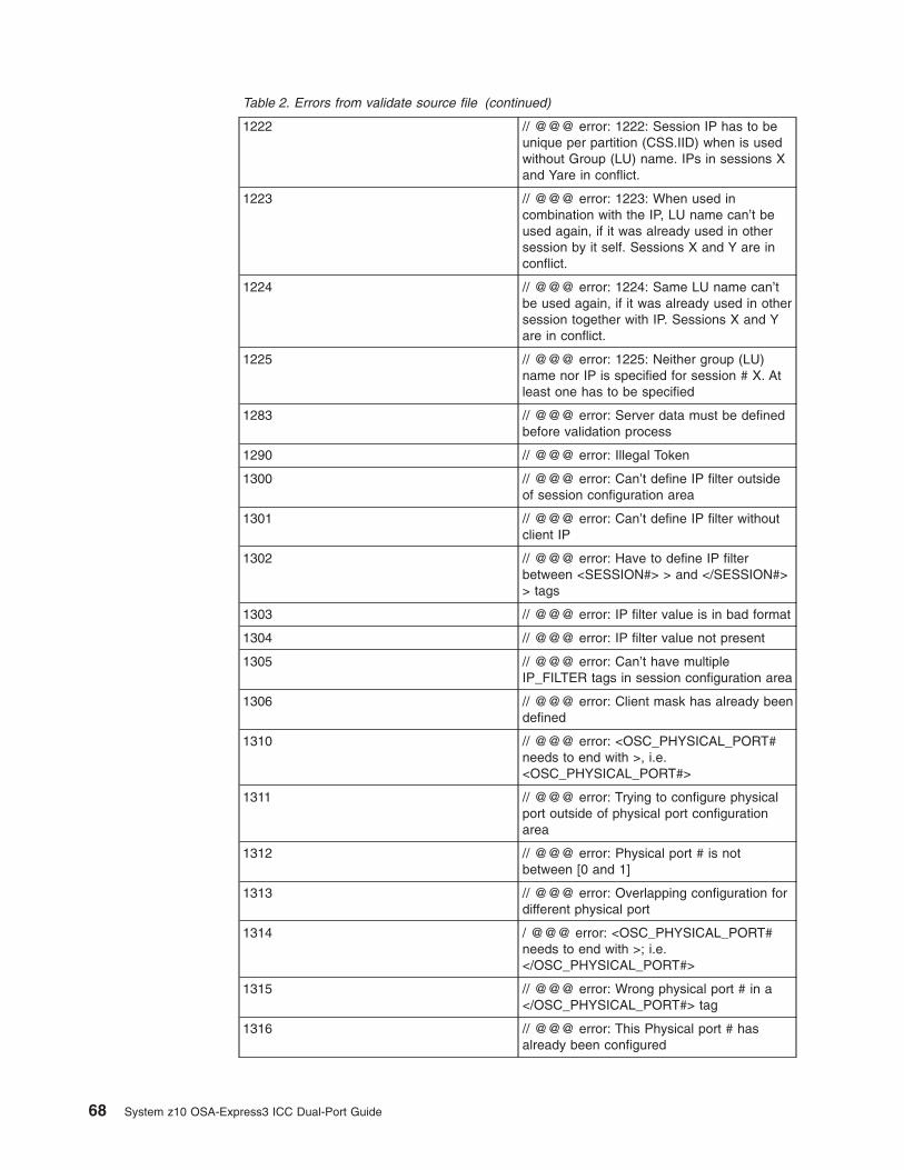
Table 2. Errors from validate source file (continued)
1222 // @@@ error: 1222: Session IP has to beunique per partition (CSS.IID) when is usedwithout Group (LU) name. IPs in sessions Xand Yare in conflict.
1223 // @@@ error: 1223: When used incombination with the IP, LU name can’t beused again, if it was already used in othersession by it self. Sessions X and Y are inconflict.
1224 // @@@ error: 1224: Same LU name can’tbe used again, if it was already used in othersession together with IP. Sessions X and Yare in conflict.
1225 // @@@ error: 1225: Neither group (LU)name nor IP is specified for session # X. Atleast one has to be specified
1283 // @@@ error: Server data must be definedbefore validation process
1290 // @@@ error: Illegal Token
1300 // @@@ error: Can’t define IP filter outsideof session configuration area
1301 // @@@ error: Can’t define IP filter withoutclient IP
1302 // @@@ error: Have to define IP filterbetween <SESSION#> > and </SESSION#>> tags
1303 // @@@ error: IP filter value is in bad format
1304 // @@@ error: IP filter value not present
1305 // @@@ error: Can’t have multipleIP_FILTER tags in session configuration area
1306 // @@@ error: Client mask has already beendefined
1310 // @@@ error: <OSC_PHYSICAL_PORT#needs to end with >, i.e.<OSC_PHYSICAL_PORT#>
1311 // @@@ error: Trying to configure physicalport outside of physical port configurationarea
1312 // @@@ error: Physical port # is notbetween [0 and 1]
1313 // @@@ error: Overlapping configuration fordifferent physical port
1314 / @@@ error: <OSC_PHYSICAL_PORT#needs to end with >; i.e.</OSC_PHYSICAL_PORT#>
1315 // @@@ error: Wrong physical port # in a</OSC_PHYSICAL_PORT#> tag
1316 // @@@ error: This Physical port # hasalready been configured
68 System z10 OSA-Express3 ICC Dual-Port Guide

Table 2. Errors from validate source file (continued)
1317 // @@@ error: Physical port # has to be adecimal number
Table 3. Warnings from validate source file
Code Text
506 // @@@ warning: 506 This session is inDefinition Error state because CSS is notdefined in IOCDS
507 // @@@ warning: 507 This session is inDefinition Error state because IID is notdefined for CSS in IOCDS
508 // @@@ warning: 508 This session is inDefinition Error state because Device is notdefined for IID in IOCDS
509 // @@@ warning: 509 This session is inDefinition Error state because device is notdefined in IOCDS
Table 4. Errors from validate panels
Code Text
1010 // @@@ Error 1010: Session # X andsession # Y are defining same device; i.e.same css/mifid/device
1042 // @@@ Error 1042: Invalid server IP value:
1046 // @@@ Error 1046: Unsupported nameformat: XXXXX
1052 // @@@ Error 1052: Invalid server portvalue: XXXXX
1055 // @@@ Error 1055: Host port value usedfor previous physical port definition
1056 // @@@ Error 1056: Host IP value used forprevious physical port definition
1057 // @@@ Error 1057: Host IP for PhysicalPort 0 and Physical Port 1 are defined in thesame segment
1082 // @@@ Error 1082: Invalid server LANPARM value: XXXXX
1092 // @@@ Error 1092: Invalid server MTUvalue: XXXXX
1132 // @@@ Error 1032 :Session # X has out ofrange CSS value.
1142 // @@@ Error 1042 :Session # X has out ofrange IID value.
1152 // @@@ Error 1052 :Session # X has out ofrange deviceNumber value.
1162 // @@@ Error 1162: Session #X has invalidgroup name length
1163 // @@@ Error 1163: Session #X has invalidgroup name
Chapter 7. Error and warning messages 69

Table 4. Errors from validate panels (continued)
1172 // @@@ Error 1172: Session #X has invalidsession IP value
1182 // @@@ Error 1082 :Session # X has invalidType.
1202 // @@@ Error 1202 :Session # X has invalidRSP value.
1212 // @@@ Error 1212 :Session # X has invalidRTO value.
1221 // @@@ Error 1221 : LU (group) name hasto be unique per partition (CSS.IID). LUnames in sessions X and ″ Y are in conflict.
1222 // @@@ Error 1222 :Session IP has to beunique per partition (CSS.IID) when is usedwithout Group (LU) name. IPs in sessions Xand Y are in conflict.
1223 // @@@ Error 1223 :When used incombination with the IP, LU name can’t beused again, if it was already used in othersession by it self. Sessions X and Y are inconflict.
1224 // @@@ Error 1224: Same LU name can’tbe used again, if it was already used in othersession together with IP. Sessions X and Yare in conflict.
1225 // @@@ Error 1225: Neither group (LU)name nor IP is specified for session # X. Atleast one has to be specified.
1303 // @@@ Error 1303 Session #X has invalidIP mask
Table 5. Warnings from validate panels
Code Text
62 // @@@ Warning 62 :Invalid server gatewayvalue: XXXXX
72 // @@@ Warning 72:Invalid serversubnetMask value: XXXXX
506 // @@@ warning: Session X is in DefinitionError state because CSS is not defined inIOCDS
507 // @@@ warning: Session X is in DefinitionError state because IID is not defined forCSS in IOCDS
508 // @@@ warning: Session X is in DefinitionError state because device is not defined forIID in IOCDS
509 // @@@ warning: Session X is in DefinitionError state because device is not defined inIOCDS
70 System z10 OSA-Express3 ICC Dual-Port Guide

Appendix A. Network topology diagrams
Network topology diagram 1In the topology diagram shown in Figure 45, there is no default gateway and bothconnections to OSA-ICC physical ports are private isolated subnets. WhenOSA-ICC dual-port connections are not routed, communication is available only toclients on the same subnet with the OSA-ICC physical port. Remote clients are notallowed to communicate with OSA-ICC.
Network topology diagram 2In the topology diagram shown in Figure 46 on page 72, there is a local networkattached to each physical port. This allows bidirectional communication with localclients and an OSA-ICC physical port connection. Remote clients can alsocommunicate with OSA-ICC because there is an established path with the router.Although this path exists and allows inbound traffic, all outbound traffic is routedthrough Physical Port 0 because the default gateway resides on this subnet.
Figure 45. Network topology Diagram 1
© Copyright IBM Corp. 2009 71

Network topology diagram 3In the topology diagram shown in Figure 47 on page 73, this network topologyoperates in a similar manner as the topology diagram shown in Figure 46. Insteadof the default gateway being defined for the subnet of physical port 0 is defined forphysical port 1. The same principle applies that remote clients can only accessOSA-ICC from either port if they both have a connection to the router. However,outbound traffic is routed only through Physical Port 1 because this is the subnet onwhich the default gateway is defined.
Figure 46. Network topology Diagram 2
72 System z10 OSA-Express3 ICC Dual-Port Guide

Network topology diagram 4In the topology diagram shown in Figure 48 on page 74, remote client connectionsto and from the routed OSA-ICC port (the port with the Default Gateway defined)are bidirectional unless the remote client resides on the same subnet as thenon-routed OSA-ICC port.
Figure 47. Network topology Diagram 3
Appendix A. Network topology diagrams 73

Network topology diagram 5The topology diagram shown in Figure 49 on page 75 is similar to that shown inFigure 48, where remote client connections to and from the routed OSA-ICC port(the port with the Default Gateway defined) are bidirectional unless the remoteclient resides on the same subnet as the non-routed OSA-ICC port.
Figure 48. Network topology Diagram 4
74 System z10 OSA-Express3 ICC Dual-Port Guide

Figure 49. Network topology Diagram 5
Appendix A. Network topology diagrams 75

76 System z10 OSA-Express3 ICC Dual-Port Guide

Appendix B. Error codes that can be returned for anAdvanced Facilities Function
Table 6 contains a list of error codes that can be returned for an Advanced FacilitiesFunction. These errors pertain mainly to development and module communication,ensuring valid SE interface interaction; however some error codes may beencountered by the user. For panels related to validation process, Chapter 7, “Errorand warning messages,” on page 63 describes all the possible error codes.
Table 6. Error codes that can be returned for an Advanced Facilities Function
Error code Description
5 The Write Per Subcommand attempts totransfer other than the record size
10 The Subcommand Count field is not 0
30 A command enabling execution ofcommands protected by the key counter wasnot already successfully executed in theCCW chain
32 Subcommand parameters 2-6 or 7 arenon-zero
33 Subcommand parameters 0 bits 0-7 arenon-zero
35 The address formed from the concatenationof SCP 0 and 1 is outside of anyimplemented OSA-3 channel address space
58 The LAN port parameter specified insubcommand parameter 1 may not bewritten
6D The Diagnostic Function code is undefined
95 The LPRT index contained in subcommandparameter 0 is invalid
96 The port corresponding to the LPRT indexcontained in subcommand parameter 0 is notan implemented physical or logical port
9E The class code contained in subcommandparameter 1 is invalid
A0 - A7 The port corresponding to the LAN portidentifier contained in subcommandparameter 0 is not in the Disabled state
A9 The LAN port parameter specified insubcommand parameter 1 is invalid for theport type of the LAN port specified by theLPRT index contained in subcommandparameter 0
AA The LAN port identifier contained insubcommand parameter 0 does notcorrespond to a physical port implemented inthe current design
AB A port diagnostic is currently in progress onsome port in the OSA-3 channel
© Copyright IBM Corp. 2009 77
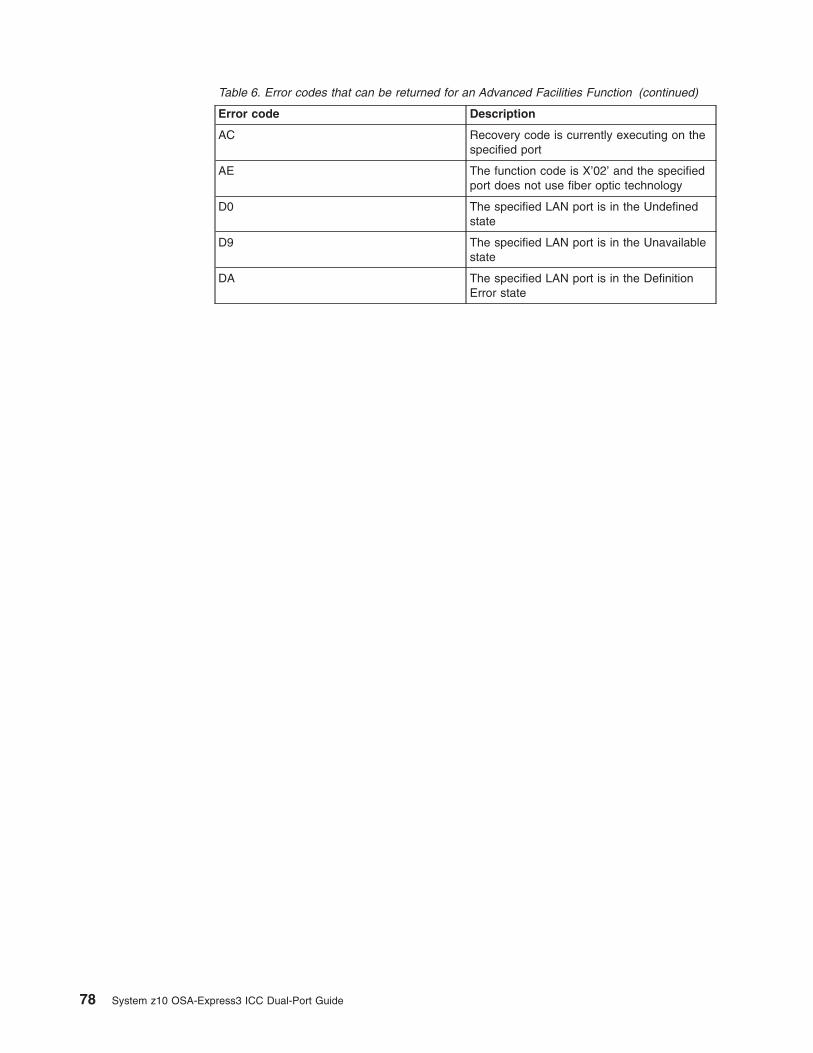
Table 6. Error codes that can be returned for an Advanced Facilities Function (continued)
Error code Description
AC Recovery code is currently executing on thespecified port
AE The function code is X’02’ and the specifiedport does not use fiber optic technology
D0 The specified LAN port is in the Undefinedstate
D9 The specified LAN port is in the Unavailablestate
DA The specified LAN port is in the DefinitionError state
78 System z10 OSA-Express3 ICC Dual-Port Guide

Notices
This information was developed for products and services offered in the U.S.A.
IBM may not offer the products, services, or features discussed in this document inother countries. Consult your local IBM representative for information on theproducts and services currently available in your area. Any reference to an IBMproduct, program, or service is not intended to state or imply that only that IBMproduct, program, or service may be used. Any functionally equivalent product,program, or service that does not infringe any IBM intellectual property right may beused instead. However, it is the user’s responsibility to evaluate and verify theoperation of any non-IBM product, program, or service.
IBM may have patents or pending patent applications covering subject matterdescribed in this document. The furnishing of this document does not give you anylicense to these patents. You can send license inquiries, in writing, to:
IBM Director of LicensingIBM CorporationNorth Castle DriveArmonk, NY 10504-1785 U.S.A.
The following paragraph does not apply to the United Kingdom or any othercountry where such provisions are inconsistent with local laws:
INTERNATIONAL BUSINESS MACHINES CORPORATION PROVIDES THISPUBLICATION ″AS IS″ WITHOUT WARRANTY OF ANY KIND, EITHER EXPRESSOR IMPLIED, INCLUDING, BUT NOT LIMITED TO, THE IMPLIED WARRANTIESOF NON-INFRINGEMENT, MERCHANTABILITY OR FITNESS FOR APARTICULAR PURPOSE. Some states do not allow disclaimer of express orimplied warranties in certain transactions, therefore, this statement may not apply toyou.
This information could include technical inaccuracies or typographical errors.Changes are periodically made to the information herein; these changes will beincorporated in new editions of the publication. IBM may make improvements and/orchanges in the product(s) and/or the program(s) described in this publication at anytime without notice.
Any references in this information to non-IBM Web sites are provided forconvenience only and do not in any manner serve as an endorsement of thoseWeb sites. The materials at those Web sites are not part of the materials for thisIBM product and use of those Web sites is at your own risk.
IBM may use or distribute any of the information you supply in any way it believesappropriate without incurring any obligation to you.
Information concerning non-IBM products was obtained from the suppliers of thoseproducts, their published announcements or other publicly available sources. IBMhas not tested those products and cannot confirm the accuracy of performance,compatibility or any other claims related to non-IBM products. Questions on thecapabilities of non-IBM products should be addressed to the suppliers of thoseproducts.
© Copyright IBM Corp. 2009 79

If you are viewing this information softcopy, the photographs and color illustrationsmay not appear.
TrademarksIBM, the IBM logo, and ibm.com® are trademarks or registered trademarks ofInternational Business Machines Corporation in the United States, other countries,or both. If these and other IBM trademarked terms are marked on their firstoccurrence in this information with a trademark symbol (® or ™), these symbolsindicate U.S. registered or common law trademarks owned by IBM at the time thisinformation was published. Such trademarks may also be registered or common lawtrademarks in other countries. A current list of IBM trademarks is available on theWeb at http://www.ibm.com/legal/copytrade.shtml.
Java and all Java-based trademarks are trademarks of Sun Microsystems, Inc. inthe United States, other countries, or both.
Microsoft, Windows, Windows NT, and the Windows logo are trademarks ofMicrosoft Corporation in the United States, other countries, or both.
Linux is a trademark of Linus Torvalds in the United States, other countries, or both.
UNIX is a registered trademark of The Open Group in the United States and othercountries.
Other company, product, and service names, which may be trademarks or servicemarks of others.
80 System z10 OSA-Express3 ICC Dual-Port Guide

Index
AActivate configuration 49
Ccancel command 54
DDebug utilities 50Display activate configuration errors 50Display active server configuration 27Display active session configuration 25Display client connections 24Display validate panel errors 33Drop session 53
EEdit server configuration 31Edit session configuration 28Edit source file 40Editing a source file, steps for 40Export source file 37Exporting a configuration file via FTP, steps for 39Exporting a configuration file, steps for 37Exporting a source file via FTP, steps for 39
IImport a configuration file, steps for 36Import source file 36Importing a configuration file via FTP, steps for 38Importing a source file via FTP, steps for 38
Llogo controls 53
MManual configuration 34
options 35
PPanel configuration options 28Ping utility 51
Qquery command 54
RRun port diagnostics 21
SSet card mode 23
Ttasks
accessing the Advance Facilities panelsteps for 16
customizing a PCOMM sessionsteps for 59
defining an OSC CHPID via HCDsteps for 10
Trace route utility 52
VValidate panel values 33Validate source file 48View port parameters 20
© Copyright IBM Corp. 2009 81

82 System z10 OSA-Express3 ICC Dual-Port Guide

Readers’ Comments — We’d Like to Hear from You
System z10Open Systems Adapter-Express3 Integrated Console Controller Dual-Port User’s Guide
Publication No. SA23-2266-00
We appreciate your comments about this publication. Please comment on specific errors or omissions, accuracy,organization, subject matter, or completeness of this book. The comments you send should pertain to only theinformation in this manual or product and the way in which the information is presented.
For technical questions and information about products and prices, please contact your IBM branch office, your IBMbusiness partner, or your authorized remarketer.
When you send comments to IBM, you grant IBM a nonexclusive right to use or distribute your comments in anyway it believes appropriate without incurring any obligation to you. IBM or any other organizations will only use thepersonal information that you supply to contact you about the issues that you state on this form.
Comments:
Thank you for your support.
Send your comments to the address on the reverse side of this form.
If you would like a response from IBM, please fill in the following information:
Name Address
Company or Organization
Phone No. E-mail address

Readers’ Comments — We’d Like to Hear from YouSA23-2266-00
SA23-2266-00
����Cut or FoldAlong Line
Cut or FoldAlong Line
Fold and Tape Please do not staple Fold and Tape
Fold and Tape Please do not staple Fold and Tape
NO POSTAGENECESSARYIF MAILED IN THEUNITED STATES
BUSINESS REPLY MAILFIRST-CLASS MAIL PERMIT NO. 40 ARMONK, NEW YORK
POSTAGE WILL BE PAID BY ADDRESSEE
International Business Machines CorporationDept. 55JA2455 South RoadPoughkeepsie, NY 12601-5400United States of America
_ _ _ _ _ _ _ _ _ _ _ _ _ _ _ _ _ _ _ _ _ _ _ _ _ _ _ _ _ _ _ _ _ _ _ _ _ _ _ _ _ _ _ _ _ _ _ _ _ _ _ _ _ _ _ _ _ _ _ _ _ _ _ _ _ _ _ _ _ _ _ _ _ _ _ _ _ _ _ _ _ _ _ _ _ _ _ _ _
_ _ _ _ _ _ _ _ _ _ _ _ _ _ _ _ _ _ _ _ _ _ _ _ _ _ _ _ _ _ _ _ _ _ _ _ _ _ _ _ _ _ _ _ _ _ _ _ _ _ _ _ _ _ _ _ _ _ _ _ _ _ _ _ _ _ _ _ _ _ _ _ _ _ _ _ _ _ _ _ _ _ _ _ _ _ _ _ _
__
__
__
__
__
__
__
__
__
__
__
__
__
__
__
__
__
__
__
__
__
__
__
__
__
__
__
__
__
__
__
__
__
__
__
__
__
__
__
__
__
__
__
__
__
__
__
__
__
_


����
Printed in USA
SA23-2266-00