(Open source hardware project) DefendLine Security...
25
DefendLine Security Complex (Open source hardware project) Magictale Studio Developers V 1.1-dev Copyright © 2006-2009 DefendLine community
Transcript of (Open source hardware project) DefendLine Security...
DefendLine Security Complex(Open source hardware project)
Magictale Studio Developers
V 1.1-dev
Copyright © 2006-2009 DefendLine community

DefendLine V 1.1-dev ii
DefendLine Security Complex
(Open source hardware project)
Table of Contents1. Preface .......................................................................................................................................... 1
1.1. Project Overview .................................................................................................................. 1
2. Product Introduction ........................................................................................................................ 2
2.1. Specific Features .................................................................................................................. 2
2.2. Component Architecture ........................................................................................................ 2
3. Hardware Part ................................................................................................................................ 5
3.1. Circuit Diagram ................................................................................................................... 5
3.2. PCB And Component Layout ................................................................................................. 7
3.3. Assembling ......................................................................................................................... 7
4. Software Part ................................................................................................................................. 9
4.1. Software Overview ............................................................................................................... 9
4.2. Microcontroller Firmware Building .......................................................................................... 9
4.3. Mobile Phone Midlet Building And Deployment ...................................................................... 11
4.4. Mobile Phone Midlet Signing ............................................................................................... 12
4.5. Web Server Deployment ...................................................................................................... 12
5. Testing, Tuning And Setting Up ...................................................................................................... 15
5.1. Microcontroller Testing and Tuning ....................................................................................... 15
5.2. Web Server Testing And Tuning ........................................................................................... 15
5.3. Mobile Phone Testing And Tuning ........................................................................................ 15
6. Command Set List ........................................................................................................................ 16
7. Examples Of Live Installations ........................................................................................................ 17
7.1. Example Of A Secured House .............................................................................................. 17
8. Maintenance ................................................................................................................................. 20
9. What Is Next? .............................................................................................................................. 21
9.1. Plugging External Accessories .............................................................................................. 21
9.2. Functionality Enhancement ................................................................................................... 21
9.3. Launchpad To New Projects ................................................................................................. 22
10. References .................................................................................................................................. 23

DefendLine V 1.1-dev 1
DefendLine Security Complex
(Open source hardware project)
1. Preface
1.1 Project OverviewDefendLine is an open hardware/software project allowing to guard remote objects via GSM channel. Why design
one more GSM based security system, nowdays there are tons of them on the market available? The answer is
simple: the systems produced in lots are rather expensive and at the same time do not quite fit everyone's needs. This
solution is based on maximally simplified microcontroller which comprises of low-cost and easy-to-find components.
Simple system does not necessary have to be primitive. This one was thought to be flexible and extendable and to
use as much functionality of external GSM device as possible. In minimal configuration it is capable of handling 4
external detectors, controlling 2 external devices by switching them on/off, performing programmed actions on timer
events, being controlled by means of SMS commands, detecting power outages and automatically switching to backup
power source. If external GSM module is presented as a mobile phone with embedded camera and Java support,
digital pictures can be taken and sent via HTTP. Extension connector might be used for LED display interfacing or
for increasing numbers of input/output lines. There is an option to interface iButton (1Wire) devices by means of
separate 2-pin connector which allows to use temperature sensors, touch memory, secure and authentification tags etc
(see http://www.maxim-ic.com/products/1-wire). Open source firmware gives obvious advantages, it boosts system's
flexibility, stimulates further improvements and development, allows custimisation and tuning to meet client needs.
All abovementioned features make the product quite competitive, uncover its huge potential to not only experienced
engineers but juniour developers and hobbists as well and open new horizons on a field of creative work.
Thank you and good luck,
DefendLine Development team
DefendLine V 1.1-dev 2
DefendLine Security Complex
(Open source hardware project)
2. Product Introduction
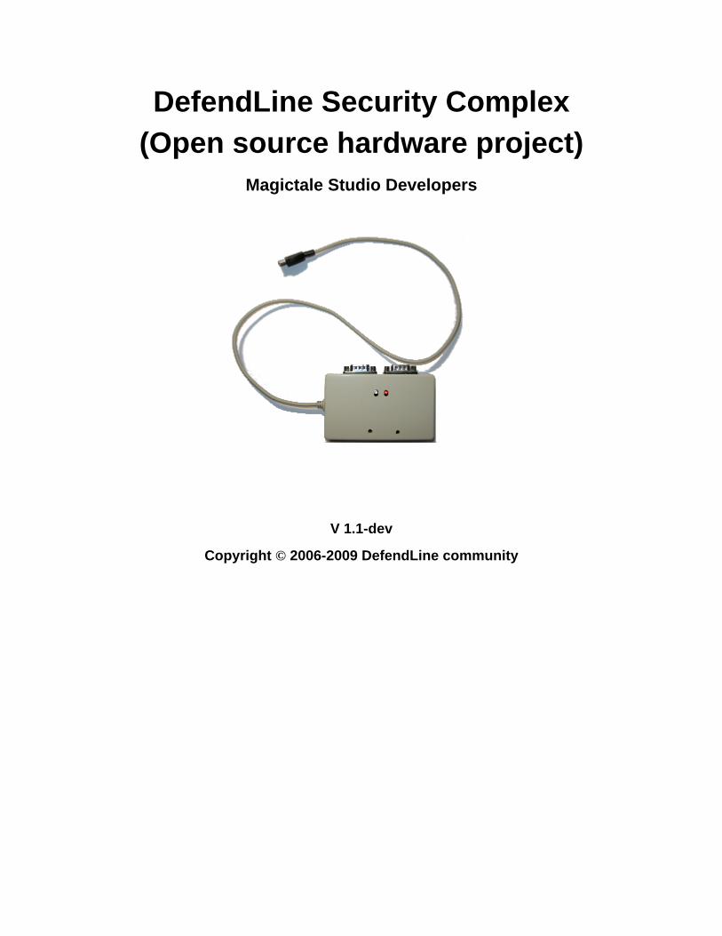
2.1 Specific FeaturesThe system has the following features which set significantly differs it from those on the market:
• It works in two different modes. The first one is a simple mode with a GPS module or a mobile phone with limited
features which allows to send notifications via SMS transport. The second mode is an extended one when the
microcontroller coupled with a mobile phone equipted with onboard camera and virtual Java machine. This mode
allows to enclose pictures taken by controlled mobile phone as well as textual descriptions of the system's state. In
later case data is sent via HTTP protocol using mobile phone TCP stack so dynamic web-based logs could be easily
organised by storing data for more than just one system;
• Immediate picture upload feature allows to send alarm and intruder's appereance before the device is disclosed and
destroyed. It may not be disclosed at all if properly disguised.
• A popular and cheap AVR8/16/32 processor is in a heart of the system is manufactured in different chip packages
including DIP which makes homemade PCB creation extremely simple;
• The microcontroller can be connected either to a mobile phone via serial interface with TTL levels or to a GSM
module via the same interface with RS232 logical levels, through TTL<->RS232 adapter inbetween;
• Extension connector might be used to increase number of inputs/outputs;
• Different variety of external chips/devices can be connected via iButton(1Wire) interface;
• Open source firmware gives unlimited freedom to any modifications/adaptations and dramatically simplifies bug
fixing;
• Assembly code gives the smallest program footprint capable of working even on processors with only 16 kbytes
onboard flash memory, modular firmware structure speeds up understanding, minimises development time and with
some limitations allows to built code to be deployed on processors with as little as 8 kbytes flash memory;
• The system can control external devices such as light in a room, pumps, compressors, fans etc by using additional
relay board;
• There is a backup power supply that activates/deactivates automatically in case of main power outages;
• Additional adapter allows to power the system from a car accumulator;
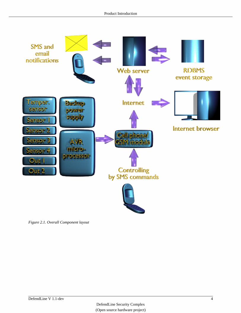
2.2 Component ArchitectureThe system comprises of two major components: Atmel AVR-based microcontroller coupled with either GSM modem
or GSM mobile phone and a web server. The first component is installed directly at location to be guarded, preferrably
masked or completely hidden. The microcontroller is then connected to up to four PIR detectors (or any other type

Product Introduction
DefendLine V 1.1-dev 3
DefendLine Security Complex
(Open source hardware project)
of normally closed connectors, magnet-hermetically sealed pair for instance), main power and backup battery supply,
optionally to external relays to control appliances like bulbs, heaters, fans. If mobile phone with embedded camera
and Java Virtual Machine (JVM) is used then pictures will be taken automatically every time when controller inputs
change states or timer goes off or SMS request to do so is received.
There are certain requirements for mobile phones to be used. First, mobile phone must have system connector with
serial port wired on it. The serial port must be accessible from inside Java application running on that phone.
Second, GPRS feature must be available on the phone. Third, in order to use full camera resolution, the procedure
of taking photos must be done not through Java API but by means of so-called keypad emulation. It means that the
microcontroller itself imitates key pressing and thus takes photos. When Java application code is launched, it is aware
of newly taken pictures, so it receives additional textual data from microcontroller, combines them with binary streams
representing new photos into HTTP request which is sent to web server via GPRS transport. In other words, fourth
requirement is support of keypad emulation. There is another issue related to Java applet signing absence of which
may result endless confirmations from mobile phone each time when COM port or GPRS connection is accessed. As
the process of becomming certified developer and obtaining a certificate for Java applet sigining is relatively costly
there are ways to overcome this obstacle for certain models of mobile phones. Current system was designed and tested
with Siemens CX65/CX70 mobile phones but can be adapted and used with any type of mobile phone if it meets all
the abovementioned requirements. If any particular model does not comply with them but has system connector and
supports AT commands it is still possible to use it, but the system will work in simple mode when there is no necessity
in web server, without option to take pictures and all notifications will be sent as SMS, not HTTP requests.
Optionally temperature sensor might be installed as well, in this case all taken pictures will have temperature measured
at the moment of exposition. Location and orientation of mobile phone with embedded camera is chosen get a viewport
of the area where one of the detectors is installed. It might capture a potential intruder when the detector triggers.
The second component, web server, is responsible for multithreaded processing of incoming requests from remote
systems, storing data into a database, displaying stored results in a convenient way as dynamic web pages. Current
implementation is based on MySQL database and set of PHP scripts but in fact due to its relatively simplicity might
be port to JSP, Perl etc. It also might be easily intergated into already existing web solutions, web portals and so on.
Current implementation supports standard PHP user authentification to prevent data to be viewed by unauthorised
individuals.
The overall system's component layout in given below:
Product Introduction
DefendLine V 1.1-dev 4
DefendLine Security Complex
(Open source hardware project)
Figure 2.1. Overall Component layout

DefendLine V 1.1-dev 5
DefendLine Security Complex
(Open source hardware project)
3. Hardware Part
3.1 Circuit DiagramThe heart of the unit is ATMEGA 16/32 microprocessor (U1) running at 3.6864 MHz (Y1 oscillator). This frequency
provides required accuracy to clock serial communication between the unit and GSM modem at 57600/115200 bps.
Y2 oscillator has standard 32768 kHz frequency for real time clock and used to invoke everyday routine procedures
such as daily report sending, switching on/off external devices etc. CONN1 is used to connect up to four PIR detectors
(or any other normally shorted sensors). CONN2 is used to control external devices. J2 connector is reserved as an
extension. It might be used to connect external display or extra sensors. J3 connector allows to perform in-system
firmware flashing, J4 allows to connect 1Wire devices such as iButton identifiers, thermosensors etc. LED1, LED2
LEDs are for unit mode indications. LED2 is preferably green (or blue) and LED1 is red. LED2 indicates alive GSM
modem/phone connection by one short flash in case of simple mode (SMS mode) or by two short flashes in case of
advanced mode (recognised mobile phone model with embedded camera supporting Java and keypad emulation is
connected). LED1 indicates alarm or disconnected sensors by long flashes in case of inactive mode. If all sensors are
in normal state LED1 won't blink in inactive mode. In case of active mode (guarding) LED1 blinks with short single
flashes regardles of sensor states. SB1, SB2 are used to change unit mode manually (the same might be done by sending
SMS command). Pressing SB1 forces the unit to toggle its mode (simple to advanced and vice versa). Pressing SB2
toggles the unit from inactive to active mode and vice versa. J5 connector is used to connect to GSM module/mobile
phone. R4 and R5 resistors are voltage divider as long as some mobile phones as Siemens switch off if the level of
input signal is higher than certain value (may vary for different vendors and models therefore R4, R5 values might
require to be adjusted). C3, C4, C5 and U2 voltage regulator supplies the unit with 5V, input voltage is applied via J1
connector. R1 and R2 form 'power good' signal which allows the program be aware when the main power failed and
the system was switched to the battery. Battery source is connected to J7 connector. D1 and D2 diodes are very simple
solution performing seamless switch from one power source to another.
The circuit diagram is done by means of gEDA tool, please see below:

Hardware Part
DefendLine V 1.1-dev 6
DefendLine Security Complex
(Open source hardware project)
594837261
CO
NN
2
IN
594837261
CO
NN
1
OU
T
2 3 41 5
10 9 8 7 6
J3 ISP
C10.1
1 2
C5
250
Y1
3.68
64 MH
z
12
LED
1
12
LED
2
D1
D2
Vcc
12
S2
12
S1
INO
UT
7805
GN
D
1
2
3
U2
9
Res
et
12
XT
AL2
13
XT
AL1
32
AR
EF
21P
D7
(OC
2)
20P
D6
(IC
P1)
19P
D5
(OC
1A)
18P
D4
(OC
1B)
17P
D3
(IN
T1)
16P
D2
(IN
T0)
15P
D1
(TX
D)
14P
D0
(RX
D)
8P
B7
(SC
K)
7P
B6
(MIS
O)
6P
B5
(MO
SI)
5P
B4
(SS
)
4P
B3
(OC
0/A
IN1)
3P
B2
(IN
T2/
AIN
0)
2P
B1
(T1)
1P
B0
(XC
K/T
0)
29(T
OS
C2)
PC
7
28(T
OS
C1)
PC
6
27P
C5
(TD
I)
26P
C4
(TD
O)
25P
C3
(TM
S)
24P
C2
(TC
K)
23(S
DA
)P
C1
22(S
CL)
PC
0
33(A
DC
7)P
A7
34(A
DC
6)P
A6
35(A
DC
5)P
A5
36(A
DC
4)P
A4
37(A
DC
3)P
A3
38(A
DC
2)P
A2
39(A
DC
1)P
A1
40(A
DC
0)P
A0
AT
meg
a16
U1
R5
180
R6
180
D0 D1
D2
D3
D4
D5
D6
D7
A0
D6
D4
D2
D0
Vcc
A1
D7
D5
D3 D1
MIS
O
SC
K
RE
S
MO
SI
Vcc
SB
1
SB
2
LD2
LD1
C20.1
Y2
32768KHz
SB
2
2 3 41
J5
MO
DE
M
21
J4
1WIR
E
2 1
J7
BA
TG
ND
+3V
R3
2.7K R42.7K
TX
VIN
1WR
C3
0.33
C40.1
2 1
J1
PO
WE
R
+8V
GN
D
RX
X2
X1
RE
S
O0
SC
K
MIS
O
MO
SI I0
X1
X2
VIN
FIL
E:
RE
VIS
ION
:
DR
AW
NB
Y:
PA
GE
OF
TIT
LEABCDEF
12
34
56
78
9
ABCDEF
12
34
56
78
9
2
34
1 5
109
87
6 1413
1211
J2
EX
T_D
ISP
O1
O0
O1
SB
1
1WR
A1
A0
TX
RX
LD1
LD2
SC
K
MO
SI
MIS
O
I0
PW
R
R2
10KR
1
2.2K
PW
R
X2
X3
X4
X3
X4
NC
NC
NC
NC
NC
NC
NC
NC
NC
NC
NC
NC
NC
NC
NC
NC
NC
NC
Def
endL
ine
3.0,
mob
ileve
rsio
n
Def
endL
ine
tea
m1
1
1.0
from
13.0
4.2
009
2
1
J6B
AT GND
+3V
Figure 3.1. Main Circuit Diagram
Hardware Part
DefendLine V 1.1-dev 7
DefendLine Security Complex
(Open source hardware project)
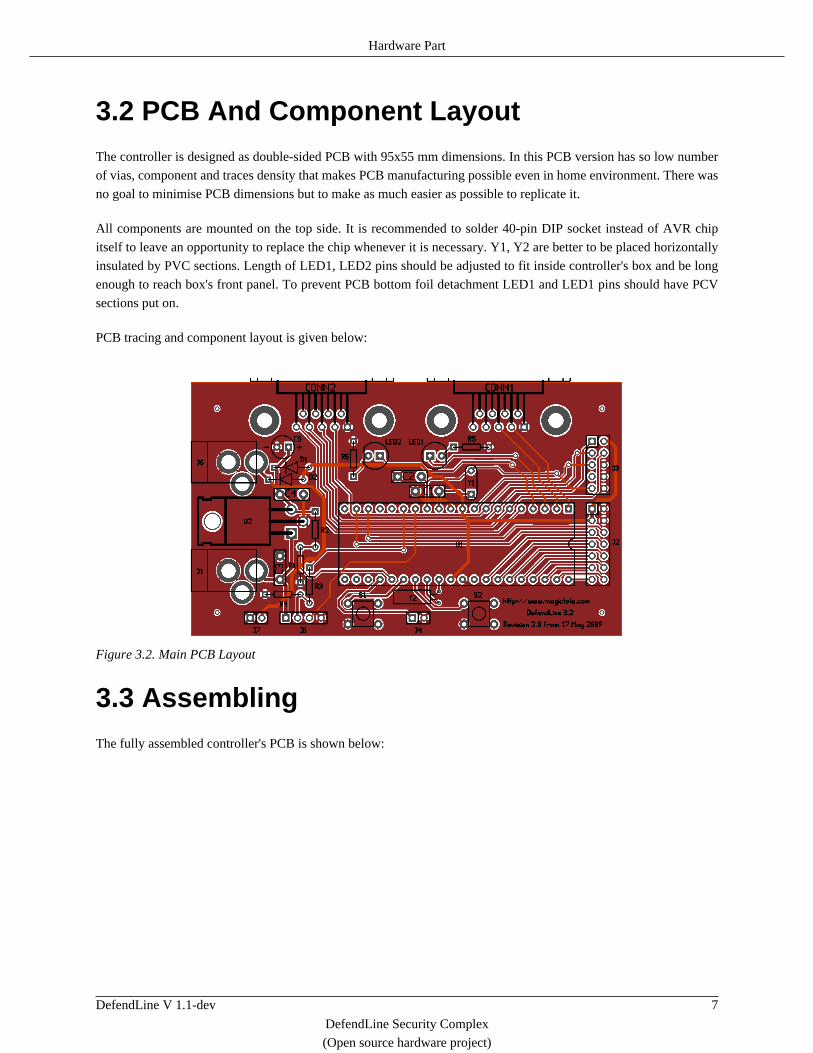
3.2 PCB And Component LayoutThe controller is designed as double-sided PCB with 95x55 mm dimensions. In this PCB version has so low number
of vias, component and traces density that makes PCB manufacturing possible even in home environment. There was
no goal to minimise PCB dimensions but to make as much easier as possible to replicate it.
All components are mounted on the top side. It is recommended to solder 40-pin DIP socket instead of AVR chip
itself to leave an opportunity to replace the chip whenever it is necessary. Y1, Y2 are better to be placed horizontally
insulated by PVC sections. Length of LED1, LED2 pins should be adjusted to fit inside controller's box and be long
enough to reach box's front panel. To prevent PCB bottom foil detachment LED1 and LED1 pins should have PCV
sections put on.
PCB tracing and component layout is given below:
Figure 3.2. Main PCB Layout
3.3 AssemblingThe fully assembled controller's PCB is shown below:

Hardware Part
DefendLine V 1.1-dev 8
DefendLine Security Complex
(Open source hardware project)
Figure 3.3. Assembled Main PCB
PCB is fitted into a box of appropriate dimensions. The photo below depicts a completed micro controller module
with Siemens CX65/70 serial cable:
Figure 3.4. Assembled Controller
DefendLine V 1.1-dev 9
DefendLine Security Complex
(Open source hardware project)
4. Software Part
4.1 Software OverviewBuilding up whole complex implies usage of Java-aware mobile phone and PHP-enabled web server. Therefore,
the task subdivides into three subtasks: to build and deploy AVR micro controller firmware, build Java application
and deploy it to mobile phone and to deploy and set PHP scripts on a web server. Before moving to the next steps
project source code must be downloaded if it has not been done yet. The project could be retrieved by the following
SVN command: svn co https://defendline.svn.sourceforge.net/svnroot/defendline
defendline .
4.2 Microcontroller Firmware BuildingTo build AVR firmware AVR studio 4 is used. It can be downloaded directly from ATMEL corporation web site.
Run AVR Studio. Select New Project menu item from AVR Studio Project menu. In the opened dialog define Project
type as Atmel AVR Assembler, type DefendLine4 in Project name field and select source code location which is in
defendline/ASM subdirectory. Click Finish button. The project tree should be created and the only initial file
DefendLine4.asm should be displayed. By right mouse click on project's Source Files item and choosing Add
Files to Project add the rest *.asm files.
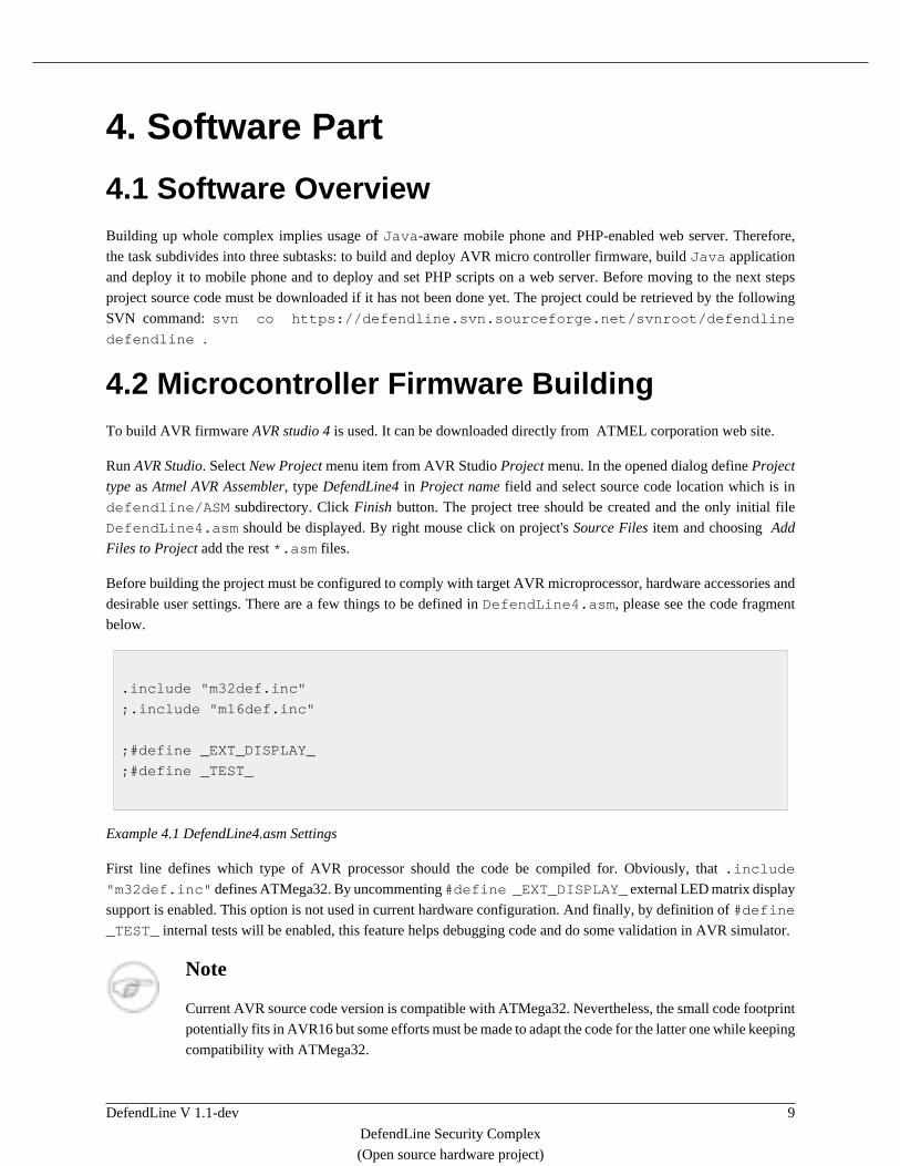
Before building the project must be configured to comply with target AVR microprocessor, hardware accessories and
desirable user settings. There are a few things to be defined in DefendLine4.asm, please see the code fragment
below.
.include "m32def.inc"
;.include "m16def.inc"
;#define _EXT_DISPLAY_
;#define _TEST_
Example 4.1 DefendLine4.asm Settings
First line defines which type of AVR processor should the code be compiled for. Obviously, that .include
"m32def.inc" defines ATMega32. By uncommenting #define _EXT_DISPLAY_ external LED matrix display
support is enabled. This option is not used in current hardware configuration. And finally, by definition of #define
_TEST_ internal tests will be enabled, this feature helps debugging code and do some validation in AVR simulator.
Note
Current AVR source code version is compatible with ATMega32. Nevertheless, the small code footprint
potentially fits in AVR16 but some efforts must be made to adapt the code for the latter one while keeping
compatibility with ATMega32.

Software Part
DefendLine V 1.1-dev 10
DefendLine Security Complex
(Open source hardware project)
There is one and only one user configuration which must be defined in Config.asm, please see the code fragment
below.
#define _CONF1_
#if defined(_CONF1_)
device_id:
.db "0123", 0, 0
DA_def:
.db "0B912143658709F1", 0, 0;12345678901 - 1st destination phone number
DA_def2:
.db "0B912143658709F1", 0, 0;12345678901 - 2nd destination phone number
;--- Textual representation of detector states ---
det_infrared:
.db "IR detector ", 0, 0
det_balcony_door:
.db "Balcony door ", 0
det_verandah_door:
.db "Door of verandah ", 0
det_main_gate:
.db "Main gate", 0
#endif
.EQU REPORT_HOUR = 0x0;
Example 4.2 Config.asm Settings
In our case this user configuration called _CONF1_. Let's enumerate all the configuration parameters. The first one,
device_id defines unique 4-character microcontroller unit identifier. It allows to distinguish units which send data
to the same server. The second and the third parameters DA_def1 and DA_def2 define mobile phone numbers
which will be used as SMS notifications recipients when the unit works in simple mode. Parameters det_infrared,
det_balcony_door, det_verandah_door, det_main_gate give more meaningful names to sensors, they
make it easier to comprehend unit's reports and notifications. And finally, REPORT_HOUR defines report hour - time,
when daily report will be sent. 0x0 means 0:00 or midnight.
The project is ready to be built. Select Build menu item from AVR Studio Build menu. DefendLine4.hex file will
be created. Flash it to the target microprocessor by means of any AVR ISP programmer.
Software Part
DefendLine V 1.1-dev 11
DefendLine Security Complex
(Open source hardware project)
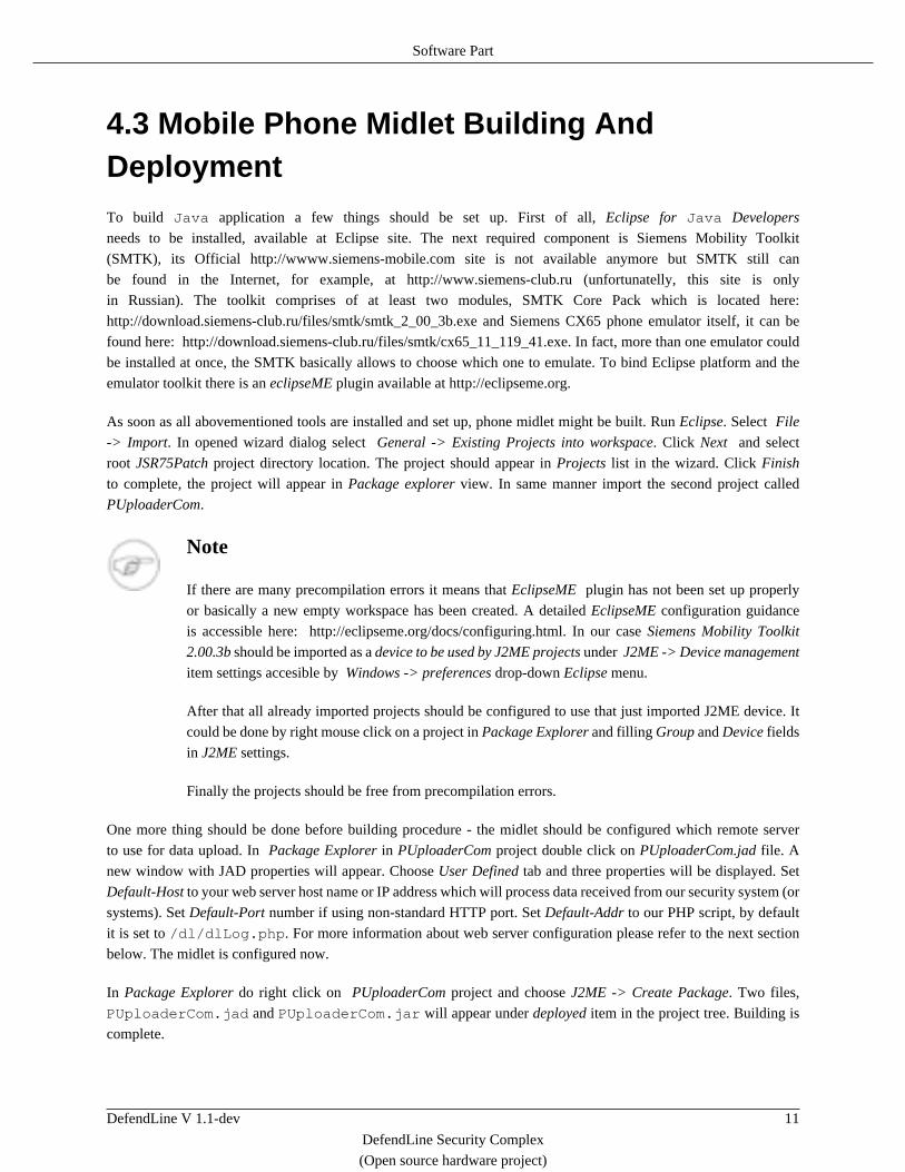
4.3 Mobile Phone Midlet Building AndDeploymentTo build Java application a few things should be set up. First of all, Eclipse for Java Developers
needs to be installed, available at Eclipse site. The next required component is Siemens Mobility Toolkit
(SMTK), its Official http://wwww.siemens-mobile.com site is not available anymore but SMTK still can
be found in the Internet, for example, at http://www.siemens-club.ru (unfortunatelly, this site is only
in Russian). The toolkit comprises of at least two modules, SMTK Core Pack which is located here:
http://download.siemens-club.ru/files/smtk/smtk_2_00_3b.exe and Siemens CX65 phone emulator itself, it can be
found here: http://download.siemens-club.ru/files/smtk/cx65_11_119_41.exe. In fact, more than one emulator could
be installed at once, the SMTK basically allows to choose which one to emulate. To bind Eclipse platform and the
emulator toolkit there is an eclipseME plugin available at http://eclipseme.org.
As soon as all abovementioned tools are installed and set up, phone midlet might be built. Run Eclipse. Select File
-> Import. In opened wizard dialog select General -> Existing Projects into workspace. Click Next and select
root JSR75Patch project directory location. The project should appear in Projects list in the wizard. Click Finish
to complete, the project will appear in Package explorer view. In same manner import the second project called
PUploaderCom.
Note
If there are many precompilation errors it means that EclipseME plugin has not been set up properly
or basically a new empty workspace has been created. A detailed EclipseME configuration guidance
is accessible here: http://eclipseme.org/docs/configuring.html. In our case Siemens Mobility Toolkit
2.00.3b should be imported as a device to be used by J2ME projects under J2ME -> Device management
item settings accesible by Windows -> preferences drop-down Eclipse menu.
After that all already imported projects should be configured to use that just imported J2ME device. It
could be done by right mouse click on a project in Package Explorer and filling Group and Device fields
in J2ME settings.
Finally the projects should be free from precompilation errors.
One more thing should be done before building procedure - the midlet should be configured which remote server
to use for data upload. In Package Explorer in PUploaderCom project double click on PUploaderCom.jad file. A
new window with JAD properties will appear. Choose User Defined tab and three properties will be displayed. Set
Default-Host to your web server host name or IP address which will process data received from our security system (or
systems). Set Default-Port number if using non-standard HTTP port. Set Default-Addr to our PHP script, by default
it is set to /dl/dlLog.php. For more information about web server configuration please refer to the next section
below. The midlet is configured now.
In Package Explorer do right click on PUploaderCom project and choose J2ME -> Create Package. Two files,
PUploaderCom.jad and PUploaderCom.jar will appear under deployed item in the project tree. Building is
complete.

Software Part
DefendLine V 1.1-dev 12
DefendLine Security Complex
(Open source hardware project)
4.4 Mobile Phone Midlet SigningBefore deployment to a mobile phone the midlet must gain access to security- sensible operations on the phone (such
as sending SMS, opening TCP and COM port connections). To know more about midlet signing please refer to a good
brief article about it: http://blog.javia.org/midlet-signing. This process usually involves significant financial expences
but fortunately there is a way to sign midlets for Siemens CX65/70 for free.
The tool for signing is called Smelter and it can be downloaded from here:
http://avkiev.kiev.ua/Siemens/Smelter/Smelter.rar. It does not required installation and usually works immediatelly
after extraction from the archive. In case if the toll fails to start complaining about abscence of some *.ocx libraries
then download OCX Control tool which is located here: http://avkiev.kiev.ua/Siemens/Soft/OcxCtrl.rar. By its means
register all required libraries and run Smelter again.
First of all, a new certificat must be created. The sequence is described below:
• Set real date/time in both mobile and computer;
• Copy Config\Policy\manufacturer.sbp file from the mobile to computer;
• Choose Tools -> Midlet Signer -> Create certificate menu;
• Enter name of your certificate (for example - your name);
• Enter path to the file Config\Policy\manufacturer.sbp which has been already downloaded from the
mobile;
• Copy der-file to the mobile to \Config\Certificate Store folder;
• Copy manufacturer.sbp to the mobile to \Config\Policy folder (replace existing).
Then, the midlet itself must be signed. The whole sequence is given below:
• Set the following permissions for the midlet by means of checking items in Tools -> Midlet Signer: FILE_READ,
FILE_READ_X65, FILE_WRITE, FILE_WRITE_X65, INTERNET, SMS, COMM, PUSHREGISTRY,
MEDIA, MEDIA_X65 ;
• Choose Tools -> Midlet Signer -> Certificate menu, then choose the certificate that has just been created;
• Choose Tools -> Midlet Signer -> Sign midlet menu, then choose PUploaderCom.jar midlet.
As result, PUploaderCom.jad will be appended with MIDlet-Certificate-1-1,
MIDlet-Jar-RSA-SHA1, MIDlet-Permissions properties. Upload both PUploaderCom.jad and
PUploaderCom.jar files to the mobile and install them in a subfolder in Applications directory. The subfolder
must be named in a way so that it is displayed first in Java application list (DefendLine or Guarding fits in most cases).
4.5 Web Server DeploymentServer-side application is implemented as a set of PHP scripts using MySQL database as data storage. Nowdays web
servers are mostly hosted on Unix platforms and their clones, that is why in this guide instructions will be given
Software Part
DefendLine V 1.1-dev 13
DefendLine Security Complex
(Open source hardware project)
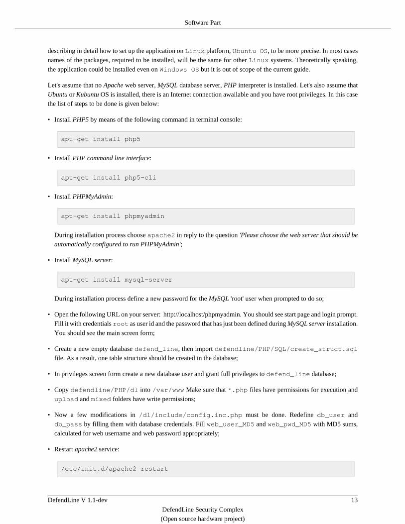
describing in detail how to set up the application on Linux platform, Ubuntu OS, to be more precise. In most cases
names of the packages, required to be installed, will be the same for other Linux systems. Theoretically speaking,
the application could be installed even on Windows OS but it is out of scope of the current guide.
Let's assume that no Apache web server, MySQL database server, PHP interpreter is installed. Let's also assume that
Ubuntu or Kubuntu OS is installed, there is an Internet connection awailable and you have root privileges. In this case
the list of steps to be done is given below:
• Install PHP5 by means of the following command in terminal console:
apt-get install php5
• Install PHP command line interface:
apt-get install php5-cli
• Install PHPMyAdmin:
apt-get install phpmyadmin
During installation process choose apache2 in reply to the question 'Please choose the web server that should be
automatically configured to run PHPMyAdmin';
• Install MySQL server:
apt-get install mysql-server
During installation process define a new password for the MySQL 'root' user when prompted to do so;
• Open the following URL on your server: http://localhost/phpmyadmin. You should see start page and login prompt.
Fill it with credentials root as user id and the password that has just been defined during MySQL server installation.
You should see the main screen form;
• Create a new empty database defend_line, then import defendline/PHP/SQL/create_struct.sql
file. As a result, one table structure should be created in the database;
• In privileges screen form create a new database user and grant full privileges to defend_line database;
• Copy defendline/PHP/dl into /var/www Make sure that *.php files have permissions for execution and
upload and mixed folders have write permissions;
• Now a few modifications in /dl/include/config.inc.php must be done. Redefine db_user and
db_pass by filling them with database credentials. Fill web_user_MD5 and web_pwd_MD5 with MD5 sums,
calculated for web username and web password appropriately;
• Restart apache2 service:
/etc/init.d/apache2 restart

Software Part
DefendLine V 1.1-dev 14
DefendLine Security Complex
(Open source hardware project)
• You should be able to login to access DefendLine data http://localhost/dl/dlRep.php. There should be an empty list.
• Imitate some data submitted by a remote security system. Open the following link: http://localhost/dl/dlLog.html,
fill the fields appeared then submit the form. Check http://localhost/dl/dlRep.php again. There should be one record.
Setting up procedure complete.
DefendLine V 1.1-dev 15
DefendLine Security Complex
(Open source hardware project)
5. Testing, Tuning And Setting Up
5.1 Microcontroller Testing and TuningPower up the microcontroller. The device will start and indicate its readiness by brief triple blink of LED2 (the blue
one). It means that the microprocessor is flashed correctly and most of hardware works. The red one led (LED1) should
blink periodically and much longer than LED2, it means the system is in inactive state and there is at least one sensor
in alarm state (or sensors are simply disconnected). Plug a mobile phone into the controller. LED2 should blink a
few times again indicating that the phone is recognised. After that LED2 should blink periodically with double or
single flashes. Double blink means that Siemens CX65/70 compatible phone is connected and the system works in
extended mode. Single blink means that simple phone is connected and the system works in SMS only mode. From
another mobile phone send SMS to the system with activate message content. LED1 should start blinking rarely
and briefly, it means that the device in active state now. In reply, the SMS sender mobile phone should receive the
command confirmation (mobile phone number must be defined in DA_def, refer to Section 4.2, “Microcontroller
Firmware Building”). For the full list of commands refer to Chapter 6, Command Set List.
5.2 Web Server Testing And TuningServer side could be tested independently from the guarding system. Remote security system might be
emulated by means of dlLog.html test form, please refer to Section 4.5, “Web Server Deployment”. The
set of scripts might be easily integrated with already existing web project: all settings are defined in one
/dl/include/config.inc.php file and styles are defined in /dl/dl.css file. The script behavior could be
easily customised as well.
5.3 Mobile Phone Testing And TuningMake sure that Java application is properly installed, please refer to Section 4.3, “Mobile Phone Midlet Building
And Deployment”, Section 4.4, “Mobile Phone Midlet Signing”. Check if the phone can establish GPRS connections.
Run PUploaderCom application while the phone is not plugged into the controller. A warning Connect accessory
must appear. Connect the phone and the controller. Run the application again. It should run without warnings. Please
make sure that the phone has enough free space, refer to Chapter 8, Maintenance.
DefendLine V 1.1-dev 16
DefendLine Security Complex
(Open source hardware project)
6. Command Set ListCurrently there are the following commands supported:
• Status command. Returns firmware revision number and the following statistical data: number of taken pictures,
number of activities (alarms), number of power failures, number of SMS requests, number of unknown SMS requests
in form today's number/total number, current system's state (active or inactive>, current sensor states;
• Activate command. Sets the system into active state if it was inactive before;
• Deactivate command. Sets the system into inactive state if it was active before;
• Snapshot command. Takes a photo remotely and uploads it to the server immediately. Not available in simple
mode;
• Set output [1|2] [ON|OFF] command. Sets output 1 or 2 to high or low level;
• Sysinfo command. Returns firmware revision and copyright data, current state of LED1 and LED2 (enabled or
disabled), current timestamp, power source (main or backup) and current level of mobile battery;
• Temp command. Returns current temperature if either DS18S20 sensor is installed or the mobile phone has its own
sensor which is accessible via AT commands.
• Set time YY/MM/DD,HH:mm:ss command. Sets microcontroller's real time clock.
Note
RTC is set automatically by fetching current timestamp from mobile phone. This command was
introduced to simplify time settings when the controller works in tandem with GSM module which
usually desn't have RTC.
• Reset command. Forces the controller to perform its re-initialisation.
DefendLine V 1.1-dev 17
DefendLine Security Complex
(Open source hardware project)
7. Examples Of Live Installations
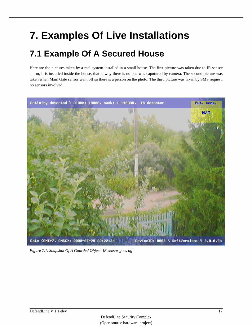
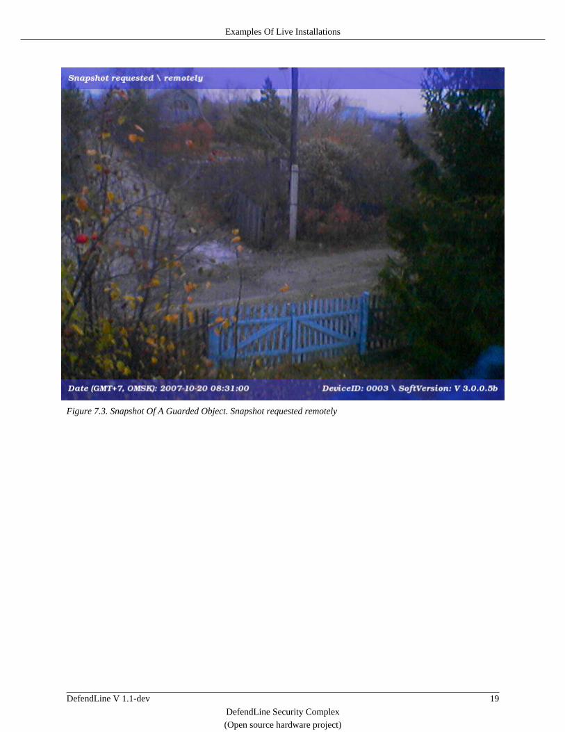
7.1 Example Of A Secured HouseHere are the pictures taken by a real system installed in a small house. The first picture was taken due to IR sensor
alarm, it is installed inside the house, that is why there is no one was caputured by camera. The second picture was
taken when Main Gate sensor went off so there is a person on the photo. The third picture was taken by SMS request,
no sensors involved.
Figure 7.1. Snapshot Of A Guarded Object. IR sensor goes off

Examples Of Live Installations
DefendLine V 1.1-dev 18
DefendLine Security Complex
(Open source hardware project)
Figure 7.2. Snapshot Of A Guarded Object. Main gate sensor goes off
Examples Of Live Installations
DefendLine V 1.1-dev 19
DefendLine Security Complex
(Open source hardware project)
Figure 7.3. Snapshot Of A Guarded Object. Snapshot requested remotely

DefendLine V 1.1-dev 20
DefendLine Security Complex
(Open source hardware project)
8. MaintenanceThe microcontroller itself requires no maintenance at all if used in reasonable temperature range. The same applies
to a GSM module in case of its usage. However, a mobile phone has a few drawbacks and needs to be maintained
every now and then.
First, SMS inbox is filled up in mobile phone as time goes by. Technically, all incomming messages are erased by
microcontroller logic as soon as they are processed. But if SMS was not handled correctly (for instance, if SMS
encoding is not supported by the microcontroller), it won't be deleted. Such messages must be deleted manually.
Second, pictures taken by Siemens CX65/70, are located in a read-only part of phone's filesystem and cannot be deleted
by a Java application. The only theoretical way to overcome the obstacle is to navigate through the phone's filesystem
by means of keypad emulation which is considered unpractical due to potentically error-prone approach and thus it
is not implemented in current microcontroller's firmware. All in all, the folder containg pictures taken by phone's
camera must be clean up manually from time to time. Depending on model revision and number of already installed
applications, Siemens CX65/70 is capable of holding up to 100-130 VGA pictures.
Third, as the mobile phone is constantly recharged and in most cases exposed to temperature drops, it minimizes
battery's lifetime and leads to its untimely degradation. There is only one solution for the problem: battery replacement.
Fourth, if source of backup power supply is used, its batteries must be replaced when they are run out of energy.
Current hardware implementation is not capable of battery charging or measuring the battery charge level yet, it might
be implemented in next revisions.
DefendLine V 1.1-dev 21
DefendLine Security Complex
(Open source hardware project)
9. What Is Next?There are three potential directions for further project evolution, each of them may exist and develop independently.
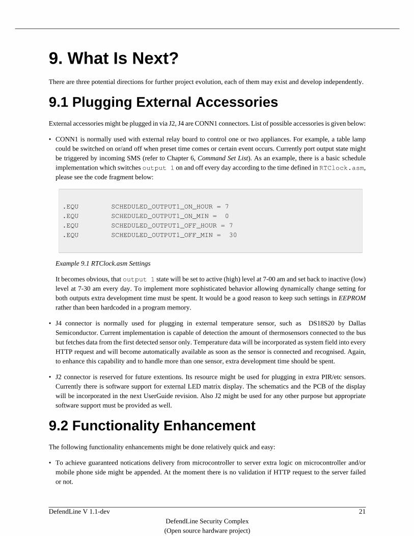
9.1 Plugging External AccessoriesExternal accessories might be plugged in via J2, J4 are CONN1 connectors. List of possible accessories is given below:
• CONN1 is normally used with external relay board to control one or two appliances. For example, a table lamp
could be switched on or/and off when preset time comes or certain event occurs. Currently port output state might
be triggered by incoming SMS (refer to Chapter 6, Command Set List). As an example, there is a basic schedule
implementation which switches output 1 on and off every day according to the time defined in RTClock.asm,
please see the code fragment below:
.EQU SCHEDULED_OUTPUT1_ON_HOUR = 7
.EQU SCHEDULED_OUTPUT1_ON_MIN = 0
.EQU SCHEDULED_OUTPUT1_OFF_HOUR = 7
.EQU SCHEDULED_OUTPUT1_OFF_MIN = 30
Example 9.1 RTClock.asm Settings
It becomes obvious, that output 1 state will be set to active (high) level at 7-00 am and set back to inactive (low)
level at 7-30 am every day. To implement more sophisticated behavior allowing dynamically change setting for
both outputs extra development time must be spent. It would be a good reason to keep such settings in EEPROM
rather than been hardcoded in a program memory.
• J4 connector is normally used for plugging in external temperature sensor, such as DS18S20 by Dallas
Semiconductor. Current implementation is capable of detection the amount of thermosensors connected to the bus
but fetches data from the first detected sensor only. Temperature data will be incorporated as system field into every
HTTP request and will become automatically available as soon as the sensor is connected and recognised. Again,
to enhance this capability and to handle more than one sensor, extra development time should be spent.
• J2 connector is reserved for future extentions. Its resource might be used for plugging in extra PIR/etc sensors.
Currently there is software support for external LED matrix display. The schematics and the PCB of the display
will be incorporated in the next UserGuide revision. Also J2 might be used for any other purpose but appropriate
software support must be provided as well.
9.2 Functionality EnhancementThe following functionality enhancements might be done relatively quick and easy:
• To achieve guaranteed notications delivery from microcontroller to server extra logic on microcontroller and/or
mobile phone side might be appended. At the moment there is no validation if HTTP request to the server failed
or not.
What Is Next?
DefendLine V 1.1-dev 22
DefendLine Security Complex
(Open source hardware project)
• Simple 12V to 6V adapter would allow to power the complex from a 12V car battery. Adapter's schematics and
PCB layout will be incorporated in the next UserGuide revision.
• Some settings would be better to move out from program memory to EEPROM and make them configurable. Some
working cells would be also better to move from RAM to EEPROM to prevent them from losing when power is
down. It would be a good idea to configure them by SMS from master phone number.
• Simple TTL to RS232 hardware converter would allow to use GSM modules such as Siemens TC35i, MC35i
etc. Converter's schematics and PCB layout will be incorporated in the next UserGuide revision.
• Bluetooth adapter capable of wired COM port emulation and plugged in the same manner as TTL to RS232
converter would make it possible to interact with new types of mobile phones even if they support only USB as a
physical connection.
Additionaly it would be desirable to have the following features but it requires more efforts:
• Remote firmware update feature via TCP over GPRS transport.
9.3 Launchpad To New ProjectsThis project is a good start to designing more complex and advanced systems due to its open nature and simplicity.
A system capable of capturing and storing not only still pictures but video as well might be a logical continuation. A
fully autonomous system working in wide temperature range with ability to recharge its batteries and designed with
less dimentions would be a goal worth to strive for. It would be great to add eventually some futuristic features as
image and voice recognition to activate/deactivate the system by voice, to distinguish friends and strangers and so on.
DefendLine V 1.1-dev 23
DefendLine Security Complex
(Open source hardware project)
10. References• The Apache Velocity Project, DocBook Framework by Velocity community,
http://velocity.apache.org/docbook
• Atmel, AVR microprocessrors manufacturer, http://www.atmel.com/
• Siemens-club, a portal dedicated to Siemens mobile phones (in Russan only), http://www.siemens-club.ru
• The Eclipse IDE Project, an open source cross-plaftorm development platform, http://www.eclipse.org
• The EclipseME Project, Eclipse plugin to develop J2ME MIDlets, http://eclipseme.org
• The Smelter Project, an Ukranian tool for Siemens mobile phones explorers,
http://avkiev.kiev.ua/Siemens/Smelter/Smelter.htm
• The phpMyAdin Project, a free tool written in PHP intended to handle the administration of MySQL over WWW,
http://www.phpmyadmin.net
• MagicTale Studio, DefendLine community home, initiator of this project, http://magictale.com