
Open-File Report 98-613 - U.S. Geological Survey .... department of the interior u.s. geological...
30
U.S. DEPARTMENT OF THE INTERIOR U.S. GEOLOGICAL SURVEY SHALLOW ELECTROMAGNETIC SURVEYS OF AN ABANDONED BUNKER, DENVER FEDERAL CENTER, COLORADO By J. Christopher Eckhart Open-File Report 98-613 This report is preliminary and has not been reviewed for conformity with U.S. Geological Survey editorial standards Any use of trade, firm or product names is for descriptive purposes only and does not imply endorsement by the U.S. Government. Denver, Colorado 1998
Transcript of Open-File Report 98-613 - U.S. Geological Survey .... department of the interior u.s. geological...
U.S. DEPARTMENT OF THE INTERIOR U.S. GEOLOGICAL SURVEY
SHALLOW ELECTROMAGNETIC SURVEYS OF AN ABANDONED BUNKER, DENVER FEDERAL CENTER, COLORADO
By
J. Christopher Eckhart
Open-File Report 98-613
This report is preliminary and has not been reviewed for conformity with U.S. Geological Survey editorial standards Any use of trade, firm or product names is for descriptive purposes only and does not imply endorsement by the U.S. Government.
Denver, Colorado 1998
SHALLOW ELECTROMAGNETIC SURVEYS OF AN ABANDONED BUNKER, DENVER FEDERAL CENTER, COLORADO
J. Christopher Eckhart
Abstract; This study compared three shallow-penetration EM systems by making surveys along identical grids over a 1940s-era, abandoned, buried coal(?) bunker at the Denver Federal Center. These systems were the Geophex GEM-2, GSSI GEM-300, and Geonics EM-31. All three systems detected many subsurface structures and objects. This report presents a folio of color maps of the results.
Purpose of study;
To examine the subsurface of the study area with differentelectromagnetic instruments, in order to develop a permanent testing area for similar types of instruments.
To compile a series of data sets for the study area in order to better understand the capabilities of selected electromagnetic instruments.
To uncover more of the history of the Denver Federal Center.
Instruments;
The three shallow penetration electromagnetic instruments we tested are commercially available, and are, to an extent, competitors for the same market niches. The EM-31, built by Geonics Ltd, Mississauga, Ontario, Canada, is described by McNeal (1960, 1996). EM-31 units have been available for many years, and there are many published case histories describing their use (some examples; Bauman and others, 1997, Rogers and others, 1996). The GEM-300 was designed by Geophex Ltd., Raleigh NC (Won and others, 1996), and is licensed to Geophysical Survey Systems Inc., Salem NH, for commercial production. The GEM-2 unit we used is a modification of that basic design, also by Geophex Ltd. All three units are two-loop frequency-domain instruments. The EM-31 operates at a fixed frequency (9.8 kHz for the newer models), while both GEM-300 and GEM-2 use up to 5 or 6 frequencies specified by the operator.
Study Area;
The study area chosen for this project ("Bldg. 20 Bunker") is a grassy rectangular area measuring approximately 43.2 meters by 87.5 meters, and is located east of Building 20, Denver Federal Center (DFC). The study area is bounded on all sides by a 1.6 to 2 meter sidewalk. It is further bounded by Second street on its westernmost side, and by a parking area on its remaining sides (sketch map follows).

Parking AreaLamp
8 Well GSA 60 (abandoned)
Lamp
81
8?iMeters
Second Street10 15
i20
DFC History:
The DFC was opened in 1942 as the Denver Ordinance Plant (OOP), to produce 30 caliber ammunition for U.S. forces to use in the Second World War. During and after the War, the DOP/DFC underwent many changes, one of which probably added the structures observed beneath the study area. A thorough records search (National Archives, 1998) was conducted, but little relevant information was found. OOP plans from 1946 show an acetylene magazine and a coal bunker or system of oil tanks immediately south of the study area. These plans show rail lines located approximately where First and Second Streets are now. Tradition has it that Kaiser Industries built, but may have never operated, a foundry for 8" artillery shells on or near the study area at the very close of the War (Kate Power, Woodward-Clyde Consultants, oral commun., 11/9/98). The area was used as a parking lot during the 1970s and 1980s, but a drillhole bored there in the early 1990s found a void: as a result, cars were kept off, and the area reverted to grass (Larry Volkening, U.S. Geological Survey, oral commun., 11/10/98). Several photographs taken in 1994 show a trench running along the western edge of the study area, as well as structural footings beneath Second Street (National Archives). It is interesting that, except for the 1994 trench (for sewer or electrical lines?), there are several documented structural features located near the study area, but none on it.
Methodology;
Each survey was performed as follows:
1. Equipment was assembled and prepared according to the manufacturers' manuals (Geophex Ltd., 1998; GSSI, 1998; Geonics Ltd., 1994).
2. Surveys began at the NW corner of the study area, which was set as the (0,0) coordinate. Surveys proceeded by walking straight lines from West to East, then East to West, and so on. Each pass was made 2.5 meters south of the previous line.
3. At the end of each survey the data collected was downloaded as directed by the manufacturer's manuals.
4. Data was gridded and plotted using Surfer 6.01 commercial software, written by Golden Software Inc., 809 14th Street, Golden CO 80401- 1866. This data is presented in figures 1-24.
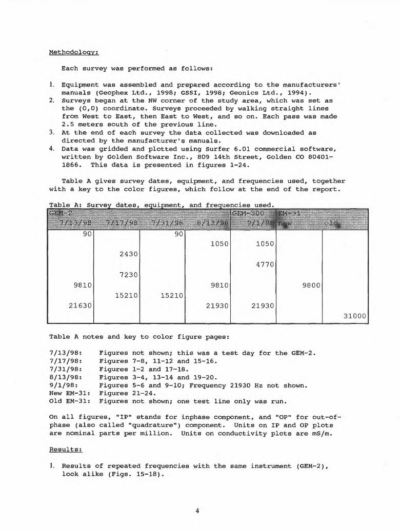
Table A gives survey dates, equipment, and frequencies used, together with a key to the color figures, which follow at the end of the report.
Table A; Survey dates, equipment, and frequencies used._______________
9810
21630
2430
7230
15210 15210
1050
9810
21930
1050
4770
21930
9800
31000
Table A notes and key to color figure pages:
7/13/98: Figures not shown; this was a test day for the GEM-2.7/17/98: Figures 7-8, 11-12 and 15-16.7/31/98: Figures 1-2 and 17-18.8/13/98: Figures 3-4, 13-14 and 19-20.9/1/98: Figures 5-6 and 9-10; Frequency 21930 Hz not shown.New EM-31: Figures 21-24.Old EM-31: Figures not shown; one test line only was run.
On all figures, "IP" stands for inphase component, and "OP" for out-of- phase (also called "quadrature") component. Units on IP and OP plots are nominal parts per million. Units on conductivity plots are mS/m.
Results:
1. Results of repeated frequencies with the same instrument (GEM-2), look alike (Figs. 15-18).
2. Results of repeated frequencies with different instruments (GEM-2 & GEM-300, GEM-2 & New EM-31), look alike (Figs. 3-6, 13-14 and 21-24).
3. EM-31 conductivities (Fig. 22) and conductivities derived from the GEM-2 (Fig. 14 data derived conductivity values are not shown) do not agree well. The GEM-2 calibration appears to be somewhat in error, giving quadrature values that are too high by about a factor of 1.5. No measurements were made at the EM-31 frequency (about 9.8 kHz) with the GEM-300, so that we did not make this test of its calibration.
4. GEM-2 nominally can use frequencies 90 Hz to 22 kHz. Data sets taken at 90 Hz (Figs. 1-2) produce images that are muted relative to those at higher frequencies. Nevertheless, certain features remain visible at 90 Hz. Note that both the wall along y = 7.5 and light post at about x = 72, y = 2 are visible on the inphase plot, fig. 1. The quadrature plot, fig. 2, shows these and other features.
5. EM-31 inphase values varied over an extreme range at this site. Because of time limitations, we did not try to bring the inphase meter on scale everywhere. This resulted in the recorded values being set at >30 (saturation value) over much of the survey area (Figs. 21,23).
6. Notice that the "wall" (linear feature at y = 7.5) is a quadrature maximum at low frequencies and a minimum at high frequencies. At intermediate frequencies the wall is obscure. EM-31 uses such an intermediate frequency (9.8 kHz), and does not see the wall well. We conclude that multifrequency systems, such as the GEM-2 and GEM-300, are advantageous for performing detailed archaeological and reconnaissance studies. However, better-calibrated systems like the EM-31 should be used where it is important to find true conductivity values, as in the studies of geology, water resources, and ore deposits.
Acknowledaement: We thank Dr. I.J. Won and Dean Keiswetter of Geophex Ltd. for lending us a newer design GEM-2 unit to make our tests.
References;
Bauman Paul D., Lockhard, Mike, Sharma, Anil, and Kellett, Richard, 1997, Case studies of 2D resistivity surveying for soils waste management, geotechnical, and groundwater contaminatant investigations: SAGEEP'97, Environmental and Engineering Geophysics Society, 10200 W. 44th Ave. #304, Wheat Ridge, CO 80033, 261-270.
Geonics Limited, 1994, EM-31 Operating Manual (For Models With TwoDigital Meters), dated Sept, 1994: Geonics Ltd., 1745 Meyerside Dr. Unit 8, Mississauga, Ontario, Canada L5T 1C6, 40 p.
Geophex, Ltd., 1998, GEM-2 Operations Manual: Geophex Ltd, 605 Mercury Street, Raleigh, NC 27603, 13 p.

Geophysical Survey Systems, Inc., 1998, GEM-300 Multi FrequencyElectromagnetic Profiler (manual), Operating System Version l.OSa, dated Jan, 1998: GSSI, 13 Klein Drive, PO Box 97, North Salem NH 03073-0097, 139 p.
McNeal, J.D., 1980, Electromagnetic terrain conductivity measurement at low induction numbers: Technical Note TN-30, Geonics Ltd., 1745 Meyerside Dr. Unit 8, Mississauga, Ontario, Canada L5T 1C6, Technical Note TN-6, 15 p.
McNeal, J.D., 1996, Why doesn't Geonics Limited build a multi-frequency EM31 or EM34?: Geonics Ltd., 1745 Meyerside Dr. Unit 8, Mississauga, Ontario, Canada L5T 1C6, Technical Note TN-30, 5 p.
National Archives, 1998: National Archives and Records Administration, Bldg. 48, DFC, Internal Record Numbers 8NS-121-97-469, Box 6: 211, 238, and 239.
Rogers, Noel T., Sandberg, Stewart K., and Powell, Greg, 1996, The effective use of electromagnetic methods to delineate a fluvial paleochannel system containing oil migration near Glenrock, Wyoming: SAGEEP'96, Environmental and Engineering Geophysics Society, 10200 W. 44th Ave. #304, Wheat Ridge, CO 80033, p. 917-926.
Won, I.J., Keiswetter, Dean A., Fields, George R.A., and Sutton, Lynn C., 1996, GEM-2: A New Multifrequency Electromagnetic Sensor: Journal of Environmental and Engineering Geophysics, v. 1, issue 2, p.129- 137.

Fig. 1 - BIdg. 20 Bunker - G
EM
2 - 90 Hz IP
80
25000-20000 15000 10000 5000 0-5000-10000--15000--20000--25000-30000--35000--40000--45000-50000--55000--60000--65000--70000-75000
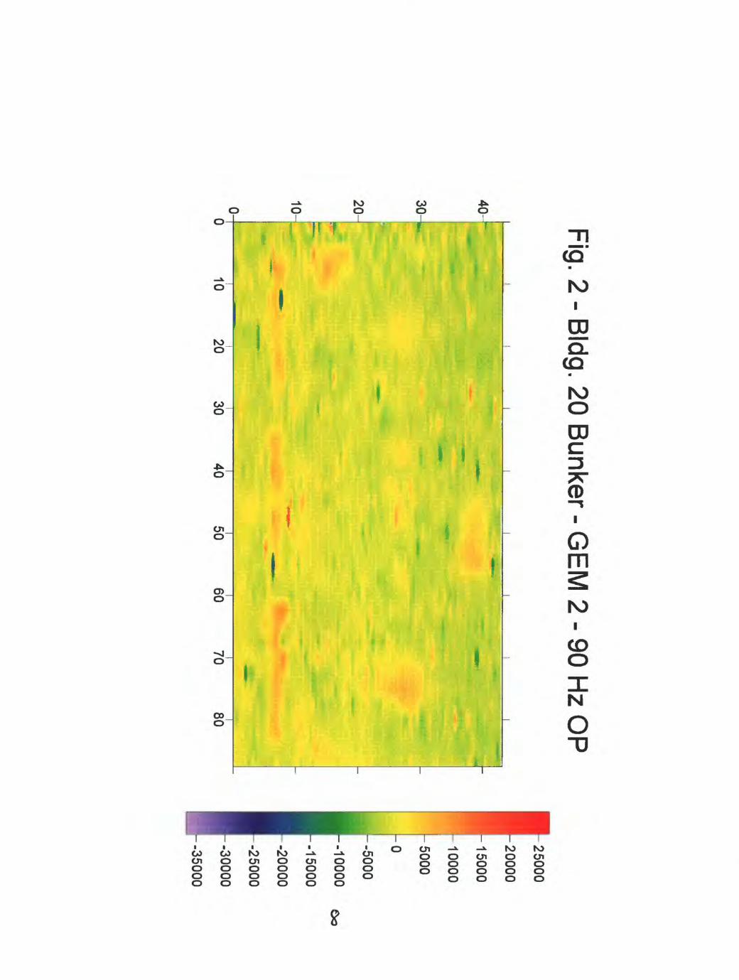
Fig. 2 - BIdg. 20 Bunker - G
EM
2 - 90 Hz O
P
40-~
30-
20-
10-.
0
1020
3040
5060
7080
(25000
20000
15000
10000
5000
ho
I -5000
-10000
-15000
-20000
-25000
-30000
-35000

Fig. 3 - BIdg. 20 Bunker - G
EM
2 -1050 Hz IP
40
30000
4050
6070
80

Fig. 4 - BIdg. 20 B
unker- GE
M 2
-10
50
Hz O
P
100-50
6070
80
30000 28000 26000 24000 22000
^20000 -18000 16000 14000 12000 10000 8000 6000 4000 2000 0 -2000
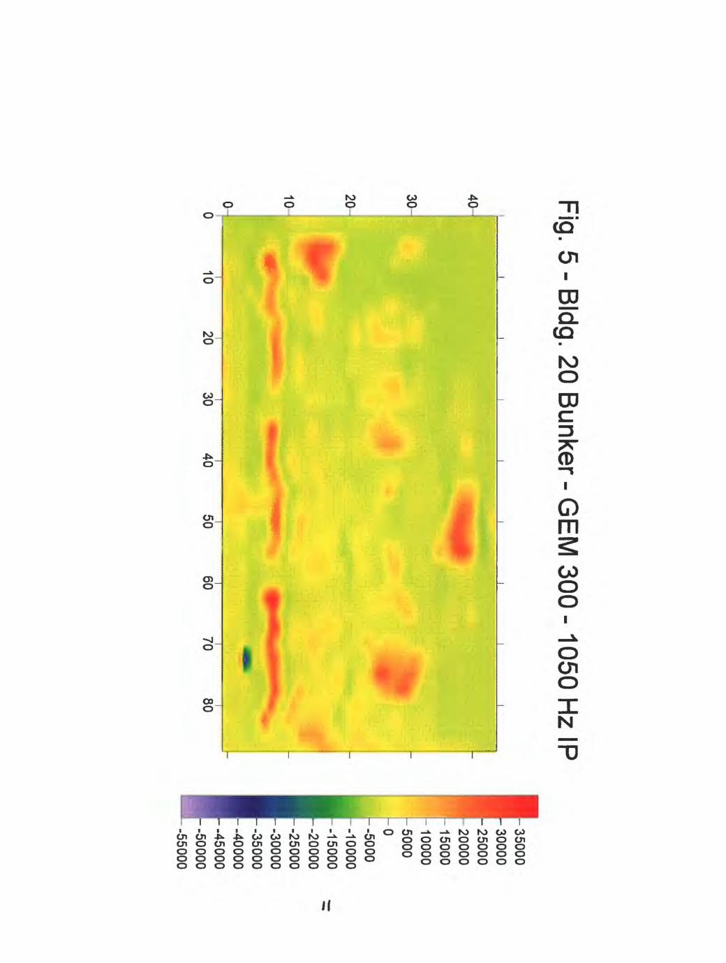
Fig. 5 - BIdg. 20 Bunker - G
EM
300 -1050 Hz IP
3020^
10-0-I 10
20i 30
4050
60i 70
80
35000300002500020000150001000050000-5000-10000-15000-20000-25000-30000-35000-40000-45000-50000-55000
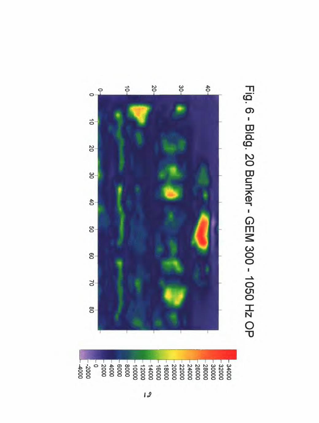
Fig. 6 - BIdg. 20 B
unker - GE
M 300 -1050 H
z OP
40
1030
4050
6070
80
t 34000 32000 30000 28000
r26000 24000 22000
h20000 18000 16000 14000 12000 10000 8000 6000 4000 2000 0-2000-4000

Fig. 7 - BIdg. 20 Bunker -G
EM
2 - 2430 Hz IP
40-
30-
20-
10-
10
.*.
2030
4050
6070
80
50000
- 40000
30000
20000
10000
i-O--10000
-20000
-30000
-40000
--50000
-60000
-70000
--80000

Fig. 8 - BIdg. 20 B
unker - GE
M 2 - 2430 H
z OP
40
6070
80
4000038000360003400032000300002800026000240002200020000180001600014000120001000080006000-4000 2000 0-2000
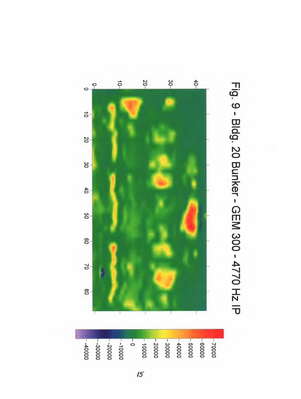
Fig. 9 - BIdg. 20 B
unker - GE
M 300 - 4770 H
z IP
40
-
70000
60000
50000
40000
!- 30000
20
000
10000
0 -10000
20000
-30000
-40000

Fig. 10 - BIdg. 20 Bunker- G
EM
300 - 4770 Hz O
P
40-
30-
6070
80
-45000
-40000
35000
30000
25000
20000
15000
10000
5000
0

Fig. 11 - BIdg. 20 B
unker - GE
M 2 - 7230 H
z IP
80
90000
80000
70000
60000
"}-50000
40000
30000
20000
10000
0--10000
--20000
--30000
--40000
--50000
--60000
-70000
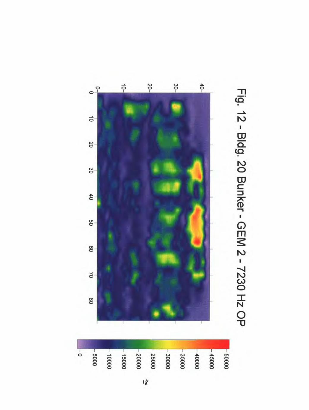
Fig. 12 - BIdg. 20 Bunker - G
EM
2 - 7230 Hz O
P
40-
1020
3040
5060
7080
50000
-45000
40000
35000
30000
25000
20000
15000
10000
5000
0

Fig. 13 - Bldg. 20 B
unker -GE
M 2 - 9810 H
z IP
40-
90000
80000
70000
60000
50000
40000
30000
20000
10000
0 -10000
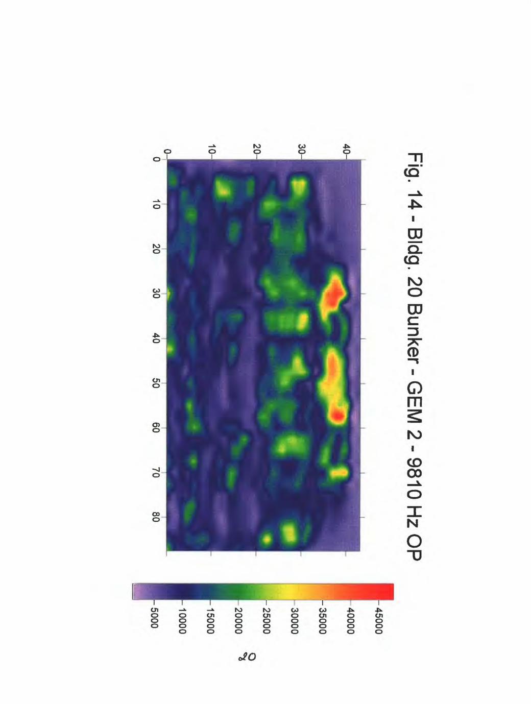
Fig. 14 - BIdg. 20 Bunker - G
EM
2 - 9810 Hz O
P
50 60
70 80
t 45000
40000
-35000
30000
,-25000
20000
15000
10000
5000

Fig. 15 - BIdg. 20 B
unker - GE
M 2 -1
52
10
Hz IP
7080
1100001000009000080000700006000050000400003000020000100000--10000-20000-30000-40000--50000-60000-70000

Fig. 16 - BIdg. 20 Bunker - G
EM
2 -15210 Hz O
P
2010-0J50
60 70
80
50000
45000
40000
-35000
30000
25000
20000
15000
10000
5000

Fig. 17 - BIdg. 20 B
unker - GE
M 2 -15210 H
z IP
10
5060
7080
110000
1000009000080000
70000600005000040000
3000020000100000-10000
-20000-30000-40000
-50000
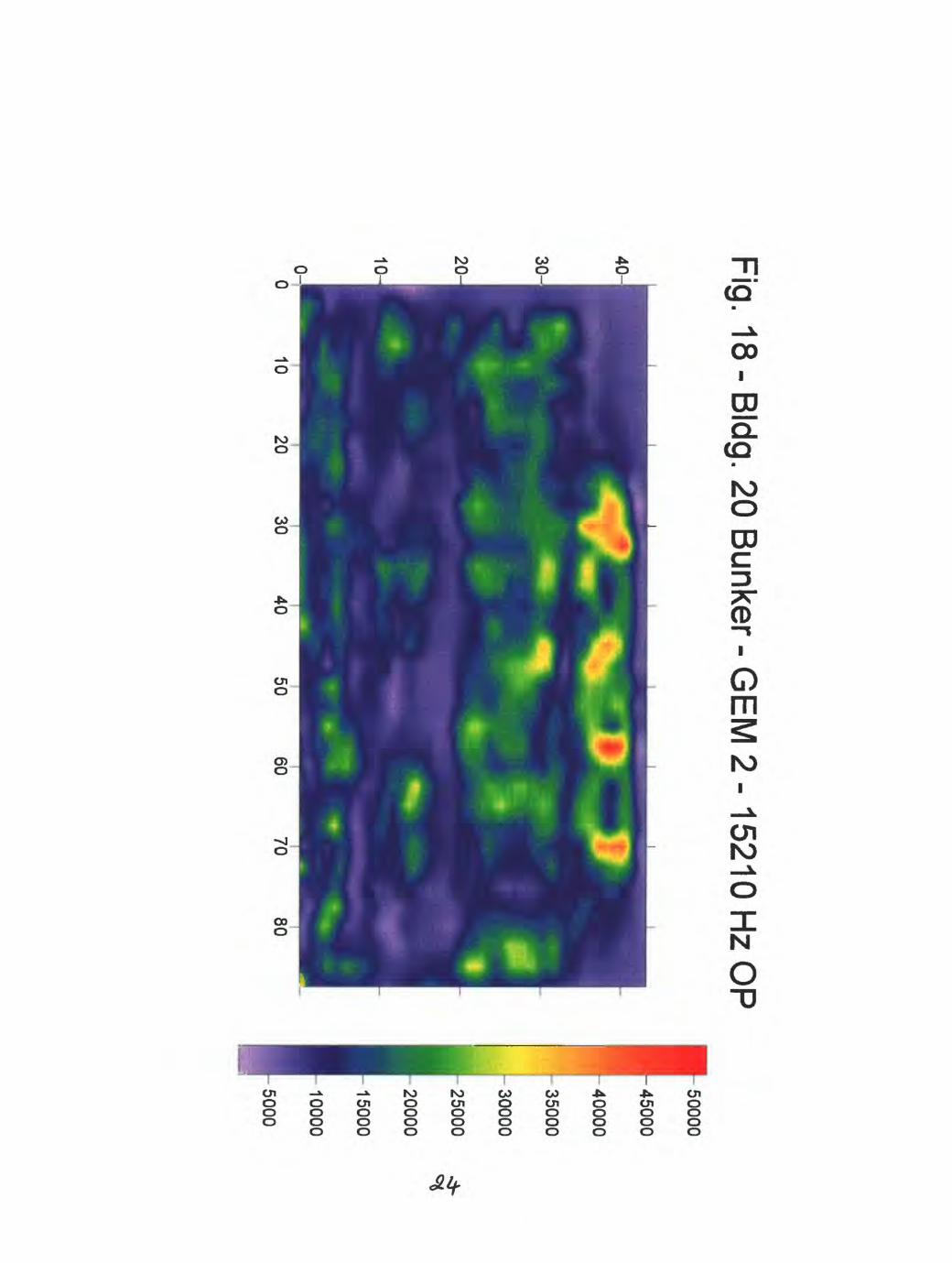
Fig. 18 - BIdg. 20 B
unker- GE
M 2 -15210 H
z OP
100-'80
50000
45000
40000
35000
30000
25000
20000
15000
10000
5000
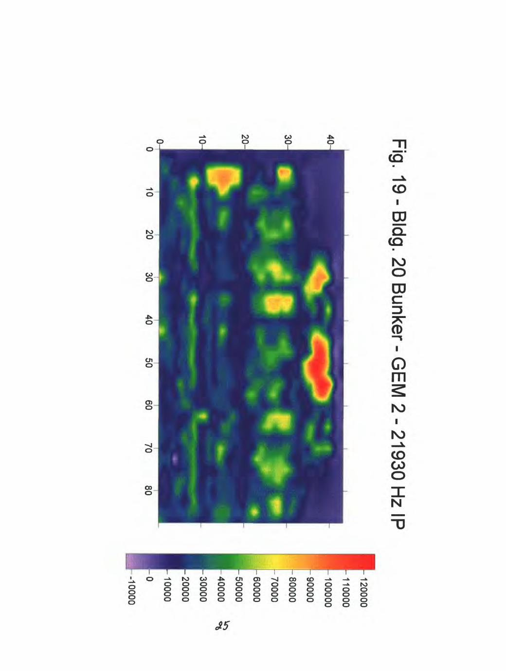
Fig. 19 - BIdg. 20 Bunker - G
EM
2 - 21930 Hz IP(
120000
110000
100000
90000
h 80000
70000
,J -60000
H-50000
H 40000
H-30000
H-20000
H-10000
I-10000
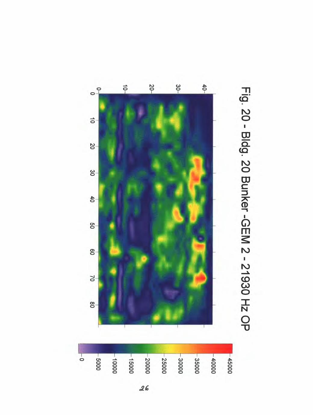
Fig. 20 - BIdg. 20 Bunker -G
EM
2 - 21930 Hz O
P
10
45000
40000
35000
30000
25000
20000
15000
10000
500050
60 70
80
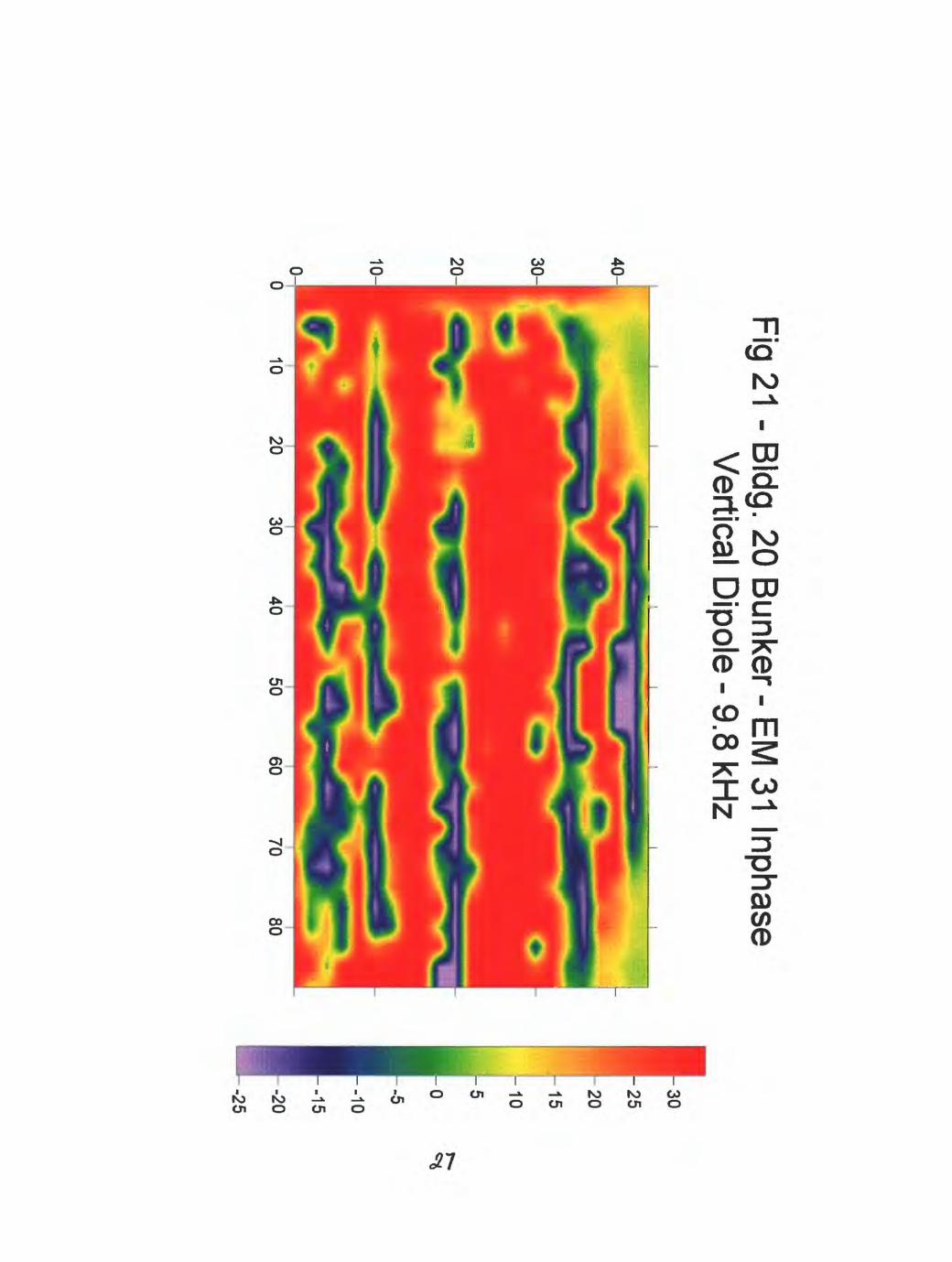
Fig 21 - BIdg. 20 Bunker - EM
31 Inphase V
ertical Dipole - 9.8 kH
z
40252015
-10
50 60
70 80
-15
-20
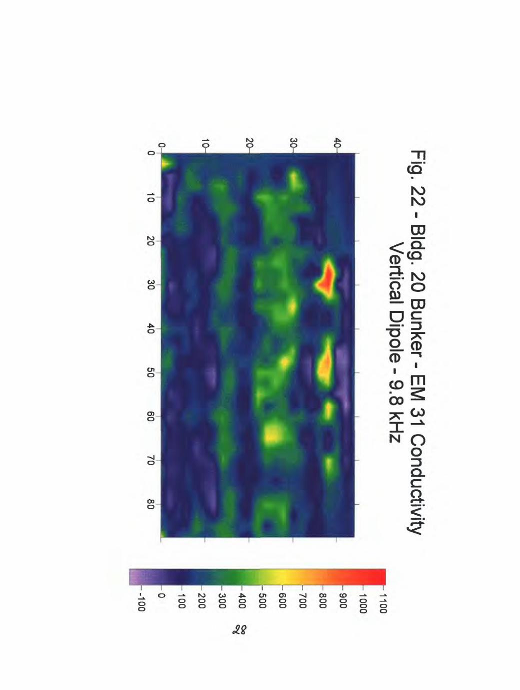
Fig. 22 - BIdg. 20 Bunker - EM
31 Conductivity
Vertical D
ipole - 9.8 kHz
4050
6070
80
1100
1000
900
800
-700
-600
500
400
300
200
100
0 -100

10
Fig. 23 - BIdg. 20 Bunker - EM
31 Inphase H
orizontal Dipole - 9.8 kH
z
1020
3040
5060
7080
403530
-25
20
15
10
5 0-5
--10
-15

Fig. 24 - BIdg. 20 Bunker - EM
31 Conductivity
Horizontal D
ipole - 9.8 kHz
5060
7080
850
800
750-700
-650
600
1-550
500
450
400-350
-300
250
200
150
100


