OPC UA Information Model Deployment - commsvr.com · paper a case study that should be useful also...
42
WHITEPAPER OPC UA I NFORMATION MODEL DEPLOYMENT
Transcript of OPC UA Information Model Deployment - commsvr.com · paper a case study that should be useful also...

WHITEPAPER
OPC UA INFORMATION MODEL DEPLOYMENT
Copyright CAS
2016
All rights reserved. No part of this document may be reproduced, stored in a retrieval system, translated, or transmitted in any form or by any means, electronic, mechanical, photocopying, recording, or otherwise, without prior written permission of CAS.
Product Address Space Model Designer
release 1.2
Document 20140301E05_DeploymentInformationModel
Date 18 April 2016
Authors Mariusz Postół, PhD. Eng. (Project Manager)
Company CAS Poland 90-527 Łódź, ul. Wólczańska 128/134 tel/fax: (42) 686 25 47; (42) 686 50 28 [email protected] http://www.cas.eu http://www.commsvr.com

Table of Contents
Preface ..................................................................................................................................................... 2
Information Processing in Industrial IT Application Domain ................................................................... 2
OPC Unified Architecture ........................................................................................................................ 5
Introduction ......................................................................................................................................... 5
Overview and Concepts ....................................................................................................................... 6
Security Model .................................................................................................................................... 6
Address Space ..................................................................................................................................... 6
Services ................................................................................................................................................ 7
Information Model .............................................................................................................................. 7
Mappings ............................................................................................................................................. 7
Profiles ................................................................................................................................................. 7
Data Access .......................................................................................................................................... 7
Alarms and Conditions ........................................................................................................................ 8
Programs ............................................................................................................................................. 8
Historical Access .................................................................................................................................. 8
Discovery ............................................................................................................................................. 8
Aggregates ........................................................................................................................................... 8
Conclusion ........................................................................................................................................... 9
Address Space and Address Space Model ............................................................................................... 9
Address Space ..................................................................................................................................... 9
Address Space Model ........................................................................................................................ 10
Information Model ................................................................................................................................ 11
Concept ............................................................................................................................................. 11
Standard Information Model ............................................................................................................. 12
ObjectTypes ................................................................................................................................... 12
VariableTypes ................................................................................................................................ 13
DataTypes ...................................................................................................................................... 15
ReferenceTypes ............................................................................................................................. 18
State machines .............................................................................................................................. 21
Information Models Creation ................................................................................................................ 22
Methodology ..................................................................................................................................... 22
Custom Models - Boiler ..................................................................................................................... 22
Adopting Companion Standard Models - Analyzer Devices Integration ........................................... 25
Introduction ................................................................................................................................... 25
Companion Specification - Information Model for Analyzers ....................................................... 26

Preface
ADI Information Model Adoption .................................................................................................. 27
ADI Model Deployment ................................................................................................................. 27
Information Model Life-cycle ................................................................................................................ 30
Design and Deployment Support .......................................................................................................... 34
Address Space Model Designer ......................................................................................................... 34
Visualization ...................................................................................................................................... 36
Build support ..................................................................................................................................... 36
Interoperability without programming ............................................................................................. 36
OPC UA E-book .................................................................................................................................. 36
OPC Foundation’s OPC UA SDK support ............................................................................................ 37
Award winning ................................................................................................................................... 37
Features ............................................................................................................................................. 37
Bibliography ........................................................................................................................................... 37

Preface
The industrial IT application domain is an integrated set of ICT systems. System integration means the necessity of the information exchange between them (the nodes of a common domain). The main challenge of deploying an industrial IT solution is that information is abstract, but unfortunately machines cannot be used to process abstraction. It is also impossible to transfer abstraction from one place to another.
The main aim of this paper is to present a new emerging engineering discipline as synergy between systematic design methodology and available tools. Bothering about information processing is usually recognized as research and development activity. Engaging R&D activity to provide information processing centric solutions has many drawbacks. It requires distinct skills and, in consequence, solving a problem and deploying the solution must be carried out as two independent phases. It is not efficient and, therefore, very expensive and risky. The OPC Unified Architecture standard addresses this problem, namely it proposes architecture, services and information modeling consistent concepts with the goal to allow vendors to release out-of-the box products ready to be used by engineers. The above-mentioned issues could be overcome by reusability and unification.
The main challenge of adopting the OPC UA standard is to converge the methodology and tools development to eliminate research and programming needs.
This whitepaper is dedicated to process architects and software developers to help them deploy the real-time process state and behavior description as a ready to use solution in a real production environment and use this description to integrate the process as a consistent part of a selected Industrial IT application domain. High-level general discussion refers to the Analyzer Device Integration (ADI) model and is illustrated using CAS Address Space Model Designer tool. It makes the paper a case study that should be useful also for the deployment of any OPC UA product.
Information Processing in Industrial IT Application Domain
By definition, the industrial IT domain is an integrated set of ICT systems. System integration means the necessity of the information exchange between them (the nodes of a common domain). ICT systems are recognized as a typical measure of information processing. The main challenge of deploying an industrial IT solution is that information is abstract – it is knowledge describing a situation in the selected environment, e.g. temperature in a boiler, car speed, account balance, etc. Unfortunately machines cannot be used to process abstraction. It is also impossible to transfer abstraction from one place to another over the network.
Fortunately, there is a very simple solution to address that impossibility, namely the information must be represented as binary data. In consequence, the terms “information” and “data” can usually be used interchangeably while talking about the ICT systems. On the other hand, they must be distinguished in the context of further discussion on information processing, because before stepping forward we must be aware of the fact that the same information could have many different but equivalent representations – different binary patterns. For example, having interconnected system A and system B, system A can use one representation, but system B another one. Moreover, to integrate them, the transferred stream of bits may not resemble any of the previous ones. It should be nothing new for us, as it is obvious that the same information written as a text in regional newspapers in English, German, Polish, etc. does not resemble one another.

Information Processing in Industrial IT Application Domain
3
To understand a newspaper we must learn an appropriate language. To understand binary data a data type must have been defined – a description how to create an appropriate bits pattern. Simplifying, the data type determines a set of valid values and rules needed to assign the information to the selected bits pattern (understand data). Therefore, to make two systems interoperable, apart from communication, they should be prepared (integrated) to be able to consume data from each other, and so communication accessibility is only a prerequisite for interoperability.
The type is usually not enough to make the data meaningful. Referring to the above example, the newspaper name (i.e. the location where the information came from) and timestamp (a single point in time when the information was valid) are attributes of the text that is representation of the information.
To have a similar ability to add common attributes to the representations of many information entities at the same time the complex data types must be used. In this context complex means that the data type must additionally define a relationship between the components of the binary data, i.e. how to selectively get a component of the complex data.
The software engineering offers two well-known and widely used relationships:
Arrays – components are indexed and all components must have a common data type.
Structures – components are named and components may have different data types.
Anyway, indexes and names must be unambiguous, and a complex data type has a responsibility to provide a precise definition of them, i.e. selectors of the components.
The complex data has a very important feature, namely all components are considered to be consistent with one another. For example, if we need to represent time at least three components must be distinguished: hour, minute, and second. In this case, even if there is no need to add any common attribute to the binary data it must be consistent, i.e. it has to represent information in a single point in time. Other criteria for describing the data consistency could also be applied.
Using complex data simplifies data integrity if there is a need to store or transfer it. If intermediaries are present, the initial data creator and the ultimate consumer need to trust those intermediaries to help provide end-to-end data integrity, because each hop is processed separately. Thus, using complex data means that the data is processed and transferred as one item what finally mitigates any risk of integrity compromising.
Using the data type definitions to describe the exposed information allows for:
Development against type definition.
Unambiguous association of the information with the data.
Having defined types in advance, clients may provide dedicated functionality, e.g. displaying the information in the context of specific graphics. Typical scenarios occur when we can define appropriate complex data types in advance. Usually the design environment offers a variety of standard types ready to be used in common cases. If the out of-the-box set is not capable of fulfilling more demanding needs users may define custom data types. They may be of generic use or they may be application domain specific.
Representing the information processed as one whole sequence of bits could be impossible or impractical for some application domains. If the information comes from a real time process, for

Information Processing in Industrial IT Application Domain
4
example a boiler or a chemical analyzer, we use an independent sensor to measure values, e.g. pressure, temperature, flow. The measuring process is independent, but pieces of information are related to each other as they describe the same physical process. If the data publisher – an OPC UA server is not running in an environment capable of creating complex data there must be taken special measures to fabricate it if required. An example of this scenario is a software application pooling data from plant floor devices using a custom protocol, e.g. MODBUS. If that is the case the protocol used to gather process data is usually not data complex aware. Reading and writing the data is accomplished using REQUEST/RESPONSE frame pairs. Moreover, one request can be used to read a set of values that has the same simple type only. Fabrication is an operation that uses a group of requests to gather components and embed them into a single value of a selected complex data type.
Fabrication of complex data is similar to using reverse engineering for recovering a big picture from details. Additionally, as it was pointed out, fabrication of complex data from pieces (i.e. composing it using building-blocks) is possible but it needs additional effort. Because processing and transferring the data over the network are not for free this approach must be well-founded. If the data volume grows paying this cost could be groundless or even impossible and then we need an alternative solution, i.e. possibility to process and transfer the data piece by piece. In such a case the consistency could be achieved by timestamps associated with each piece separately and partial data processing is possible if pieces can be accessed selectively. The proposed selection mechanisms of components for the complex data are rather static, i.e. they limit the internal structure and meaning (semantics) of the relations, but still can be successfully used for that purpose. Hence, to overcome those limits the reference concept could be introduced. Reference links two elements together, where source and target roles are distinguished in this couple. Reference could also represent information. Adding randomly specific references to particular pieces of data we can create unlimited structures. For example, let’s try to describe a car. We need partial information about the main car body and four references to the tires as components, but for the spare tire we need different reference kind, say a spare component to point out a different relationship for this case. Following the reference concept we actually introduced a new selection mechanism, namely browsing. Nowadays, as a consequence of using references, we are able to replace a static newspaper with a dynamic website, where information is represented using hypertext instead of using text.
The concepts and terms presented above are well known and widely used by programmers and website authors, and probably recognized by them as an unacceptable simplification. As there are people working on processing and exposing information professionally, a question arises why we are bothering about it. There is one simple reason: the offered services are unsatisfactory. There are two issues that can be recognized. Programmers offer dedicated solutions with the goal of meeting precisely defined requirements of selected stakeholders. The webmasters offer the possibility for freely exposing any information you need, but the representation is hard to be processed by other programs, because the references are described (has meaning) in the native language.
In contrast to the offer of programmers and webmasters we face the biggest challenge of providing a generic solution that allows us to expose any complex information, transport it over the network and finally process it on the assumption that all these three operations can be done by independent parties. In this context generic means here that only out of the box products and existing infrastructure are acceptable. Independent parties mean no need for special agreements made to guarantee interoperability case by case. In other words, common rules must be observed instead of case specific agreements. The rules must be valid now, in the future, and for all application domains called industrial IT. Having an adequate rules specification in hands we will be able to ask programmers and webmasters to fulfil our requirements and we will finally obtain a universal, flexible enough solution based on best practice. This whitepaper is all about the selection of appropriate specifications and deployment of rules in the context of information processing.

OPC Unified Architecture
5
To meet the requirements presented above it is proposed to select OPC Unified Architecture specification as a foundation for further work. One of the main goals of the OPC Unified Architecture (OPC UA) is to provide a consistent mechanism for the integration of process control and business management systems. It is assumed that it should be robust and the implementation should be platform independent. In the next section I will examine technologies and paradigms used as a framework for the development of the OPC UA standard and discuss their impact on the final result.
OPC Unified Architecture
Introduction
OPC Unified Architecture (OPC UA) is described in a layered set of specifications broken into parts. It is purposely described in abstract terms and only in selected parts coupled to existing technology on which software can be built. This layering is intentional and helps isolate changes in OPC UA from changes in the technology used to implement it.
The OPC UA specifications are organized as a multi-part document combined in the following sets:
Core specification
Access type specification
Utility specification
The first set specifies core capabilities of OPC UA. Those core capabilities define the concept and structure of the Address Space and the services that operate on it. The access type set applies those core capabilities to specific models of data access. Like in OPC Classic, there are distinguished: Data Access (DA), Alarms and Conditions (A&C) and Historical Access (HA). A new access mode is provided as a result of introducing the programs concept and aggregation mechanisms. This set also specifies the UA server discovery process. Those mechanisms are not directly dedicated to support data exchange, but play a very important role in the whole interoperability process.
The core set contains the following specifications:
Part 1 – Overview and Concepts: presents the concepts and overview of OPC Unified Architecture.
Part 2 – Security Model: describes the model for securing interactions between OPC UA clients and servers.
Part 3 – Address Space Model: describes an object model that servers use to expose underlying real-time processes to create an OPC UA connectivity space.
Part 4 – Services: specifies the services provided by OPC UA servers.
Part 5 – Information Model: specifies information representations - types that OPC UA servers use to expose underlying real-time processes.
Part 6 – Mappings: specifies transport mappings and data encodings supported by OPC UA.
Part 7 – Profiles: introduces the concept of profiles and defines available profiles that are groups of services or functionality.
OPC Unified Architecture
6
The access type set contains the following specifications:
Part 8 – Data Access: specifies the use of OPC UA for data access.
Part 9 – Alarms and Conditions: specifies the use of OPC UA support for accessing alarms and conditions.
Part 10 – Programs: specifies OPC UA support for accessing programs.
Part 11 – Historical Access: specifies the use of OPC UA for historical access. This access includes both historical data and historical events.
The utility specification parts contain the following specifications:
Part 12 – Discovery: introduces the concept of the Discovery Server and specifies how OPC UA clients and servers should interact to recognize OPC UA connectivity.
Part 13 – Aggregates: describes ways of aggregating data.
Overview and Concepts
This part describes the goal of OPC UA and introduces the following models to achieve it:
Address Space and information model to represent structure, behavior, semantics, and infrastructure of the underlying real-time system.
Message model to interact between applications.
Communication models to transfer data over the network.
Conformance model to guarantee interoperability between systems.
Security model to guarantee cyber security addressing client/server authorization, data integrity and encryption.
Security Model
This part describes the OPC UA security model. OPC UA provides countermeasures to resist threats that can be made against the environments in which OPC UA will be deployed. It describes how OPC UA relies upon other standards for security. The proposed architecture is structured in an application layer and a communication layer. Introduced security policies specify which security mechanisms are to be used. The server uses security policies to announce what mechanisms it supports and the client - to select one of those available policies to be used when establishing the connection.
Address Space
There is no doubt that information technology and process control engineering have to be integrated to benefit from macro optimization and synergy effect. To integrate them, we must make systems interoperable. It causes the necessity of exchanging information, but to exchange information, it has to be represented as computer centric (saveable in a binary memory) and transferable (a stream of bits) data. According to the specification, a set of objects that an OPC UA server makes available to clients as data representing an underlying real-time system is referred to as its Address Space. The breaking feature of the Address Space concept allows representing both real

OPC Unified Architecture
7
process environment and real-time process behavior - by a unique means, mutually understandable by diverse systems.
Services
The OPC UA services described in this part are a collection of abstract remote procedure calls that is to be implemented by the servers and called by the clients. The services are considered abstract because no particular implementation is defined in this part. The part Mappings describes more specific mappings supported for implementation. Separation of the service definition and implementation allows for harmonization with new emerging technologies by making new mappings.
Information Model
To make the data exposed by the Address Space mutually understandable by diverse systems, the information model part standardizes the information representation as computer centric data. To promote interoperability, the information model defines the content of the Address Space of an empty OPC UA server. This content can be used as a starting browse point to discover all information relevant to any client. Definitions provided in this part are considered abstract because they do not define any particular representation on the wire. To make the solution open for new technologies, the representation mappings are postponed to the part Mappings. The solution proposed in this model is also open to defining vendor specific representations.
Mappings
This part defines mappings between abstract definitions contained in the specification (e.g. in the parts: Information Model, Services, Security Model) and technologies that can be used to implement them. Mappings are organized into three groups: data encodings, security protocols and transport protocols. Different mappings are combined together to create stack profiles.
Profiles
This part describes the OPC UA profiles as groups of services or functionality that can be used for conformance level certification. Individual features are grouped into conformance units, which are further grouped into profiles. All OPC UA applications shall implement at least one stack profile and can only communicate with other OPC UA applications that implement the same stack profile. Servers and clients will be tested against the profiles. Servers and clients must be able to describe which of the features they support.
Data Access
This part describes the information model associated with the Data Access (DA) mode. It particularly includes an additional definition of variable types and a complementary description of Address Space objects. This part also includes additional descriptions of node classes and attributes needed for DA, as well as DA specific usage of services to access process data.
OPC Unified Architecture
8
Alarms and Conditions
This part describes the representation of events and alarms in the OPC UA Address Space and introduces the concepts of condition, dialog, acknowledgeable condition, confirmable condition and alarm. To expose above information, it extends the information model defined in other parts and describes alarm specific uses of services.
Programs
This part extends the notion of methods and introduces the concept of programs as a complex, stateful functionality in a server or underlying system that can be invoked and managed by a OPC UA client. The provided definitions describe the standard representation of programs as part of the OPC Unified Architecture information model. The specific use of services is also discussed.
Historical Access
This part describes an extension of the information model associated with Historical Access (HA). It particularly includes additional and complementary definitions of the representation of historical time series data and historical event data. Additionally, this part covers HA specific usage of services to detect and access historical data and events.
Discovery
The main aim of this part is to address the discovery process that allows the clients to first find servers on the network and then find out how to connect to them. This part describes how UA clients and servers interact to exchange information on resources available on the network in different scenarios. To achieve this goal, there are introduced the concepts of a discovery server that is a placeholder of global scope information and a local discovery server, whose main task is to manage information vital to local resources. Finally, this part describes how to discover UA applications when using common directory service protocols such as UDDI and LDAP.
Aggregates
This part specifies the information model associated with aggregates and describes how to compute and return aggregates like minimum, maximum, average etc. Aggregates can be used with base (live) data as well as historical (HA) data. This part also addresses the aggregate specific usage of services.
Related articles
OPC Unified Architecture - Main Technological Features (mpostol.wordpress.com)
OPC Books & Academic Articles ( www.opcfoundation.org)
OPC UA Makes Smart Factory Possible (mpostol.wordpress.com)
OPC UA makes cloud computing possible. (mpostol.wordpress.com)

Address Space and Address Space Model
9
To read more about OPC Unified Architecture main technology features visit:
http://wp.me/p3MGZj-i
Conclusion
All of the features presented in this section are very important for assessing the specification against particular requirements vital for industrial IT application domain. For the rest of this paper they can be recognized as “must have option” to be surrounded by tools and deployment methodology to finally produce a widely accepted powerful technology. To meet the goal of this paper we will focus on the information representation rules proposed by this standard and methodology of practical deployment thereof. In this context there are two fundamental concepts introduced by the OPC UA specification:
Address Space Model – all about exposing information in a standard way.
Information Model – all about unambiguous, computer centric definition of information.
Address Space and Address Space Model
Address Space
The primary objective of the OPC UA server is to expose information that can be used by clients to manage an underlying real-time process and the entire enterprise as a large whole with the main challenge of integrating systems and management resources into one homogenous environment. Information describes the state and behavior of the process and the server must be able to transfer it in both directions. The main challenge of the OPC UA Address Space is to support this transfer in a unique and transparent way in spite of the process complexity and roles of clients in the enterprise management hierarchy.
To make the data available for further processing by computer systems it must be assured that the data is:
transferable – there must exist mechanisms to transfer the data over the network,
addressable – there must exist services to selectively access the data,
meaningful – there must exist rules (unambiguous for all interoperating parties) how to apply the semantics to bit patterns.
OPC UA Address Space concept is all about exposing the data in a standard way, so it must address the above mentioned issues, but the description of mechanisms involved in the data transfer is outside this section scope.
Generally speaking, to select a particular target piece of data we have two options: random access or browsing. Random access requires that the target item must have been assigned a globally unique address and the clients must know it in advance. We call them well-known addresses. The browsing approach means that the clients walk down available paths from entity to entity that build up the structure of data. This process is costly, because instead of jumping to a target, we need to discover the structure of the data step by step using relative identifiers. The main advantage of this approach is that the clients do not need any prior knowledge of the data structure – the clients of

Address Space and Address Space Model
10
this type are called generic clients. To minimize the cost, after having found the target, every access to it can use random access. Random access is possible since the browsing path is convertible to a globally unique address.
It seems that, in spite of the access method, we have to assign an address to all of the accessible items in the representation of the data structure. We therefore call the collection of these items the Address Space [1], [3], [5]. In this concept this atomic addressable item is called a node. Each node is a collection of Attributes (value-holders) that have values accessible locally in context of the node. To enable browsing, i.e. to represent information about the internal structure, nodes are interconnected by References (address-holders of coupled nodes).
Address Space Model
The main goal of exposing a network of nodes to clients is to create a meaningful context for the underling process data. To create the Address Space, we need to instantiate nodes and interconnect them by References. Instantiating nodes requires assigning appropriate values to Attributes. To make information internally consistent as a large whole, we need rules governing the creation and modification processes, i.e. Address Space Model. According to the model the roles of nodes in the network are well defined as a result of the definition of a set of NodeClasses. Available NodeClasses are predefined, i.e. the Address Space Model provides a strictly defined and non-extensible set of NodeClasses. Each one is assigned a dedicated function to represent well defined information at runtime. NodeClass is a formal description of the node defining the allowed Attributes and References. Each node must be an instance of the selected NodeClass.
The Address Space Model defines the following set of NodeClasses:
View: defines a subset of nodes in the Address Space.
Object: is used to represent systems, system components, real-world objects and software objects.
Variable: is used as real-time process data holders, i.e. it provides a value.
Method: is a lightweight function, whose scope is bounded by an owning object.
ObjectType: provides definition for objects.
DataType: is used to define simple and complex data types of the Variable values.
ReferenceType: is used to define the meaning of the nodes relationship.
VariableType: is used to provide type definition for variables.
It is worth noting that the ReferenceType nodes are visible in the Address Space. In contrast, a reference instance is an inherent part of a node and no NodeClass is used to represent references. In other words, any node is a collection of references, so there is no need to instantiate an additional object as reference with the role of a nodes coupler.
Accessing information by clients is the first aspect of controlling the information stream between the clients and underling process. Another one is creating and maintaining the Address Space in real-time. This activity includes also creation of data bindings with the underlying real-time process. This topic is described in more details in the section Information Model Life-cycle.
Information Model
11
Information Model
Concept
To make systems interoperable, i.e. empower common processing of information by variety of computer systems, the data transfer mechanism must be associated with a consistent information representation model. OPC UA uses an object as a fundamental notion to represent data and behavior of an underlying system. The objects are placeholders of variables, events and methods and are interconnected by references. This concept is similar to well-known object oriented programming (OOP) that is a programming paradigm using "objects" – data structures consisting of fields, events and methods – and their interactions to design computer programs. The OPC UA Information Model [1], [7] provides features such as data abstraction, encapsulation, polymorphism, and inheritance.
For the purpose of unification of the information representation the producers (servers) and consumers (clients) use the type notion. The OPC UA object model allows servers to provide type definitions for objects and their components. Type definitions may be abstract, and may be inherited by new types to reflect polymorphism. They may also be common or they may be system-specific. Object types may be defined by standardization organizations, vendors or end-users. Each type must have a globally unique identifier that can be used to provide description of the data semantics from the defining body or organization. Using the type definitions to describe the information exposed by the server allows for:
Development against type definition.
Unambiguous assignment of the semantics to the data expected by the client.
Having defined types in advance, clients may provide dedicated functionality, for example: displaying the information in the context of specific graphics. It greatly improves reusability as a result of the possibility of designing a unique context for typical Real-time Processes. As an example, the section Adopting Companion Standard Models - Analyzer Devices Integration presents a case of unification of the model for chemical analyzers.
The OPC UA information modelling concept is based on domains. A domain is a named self-contained collection of definitions. Any domain name must be globally unique - it is an identification string that defines a realm of administrative autonomy and authority of responsibility. Type definition from one domain may inherit from type definitions located in other domains. To avoid circular references domains should be organized in layers, which expand step by step the basic model provided by the OPC UA Specification.
Type definitions are exposed in the OPC UA Address Space using the specialized NodeClasses: ObjectType, DataType, ReferenceType, VariableType. The main role of the types represented by the above NodeClasses is to provide a description of the Address Space structure and to allow clients to use this knowledge to navigate to desired information in the Address Space exposed by the server. In other words, this way the clients obtain the definition of the data (metadata) using the following two concepts:
1. NodeClass – as a formal description of the node defining the allowed attributes and references. 2. Type – as a formal description of the node defining values of the allowed attributes and
references.
Information Model
12
The OPC UA Information Model concept provides a set of predefined types and rules that must be applied to expand it. Even though the OPC UA specification contains a rich set of predefined types, the type concept allows designers to freely define types according to the application needs. New types are derived from the existing ones. The derived types inherit all features from the base types but can include modifications to make the new types more appropriate for information the designers are representing. To expand the standard model, independent domains must be defined. This new information model covered by the domain may be the subject of a companion specification or proprietary release. In any case the definitions must be uniquely named and self-contained except for external type references. All not predefined types (not belonging to the standard domain) must be exposed in the Address Space.
Types are called metadata since they describe the data structure and not the actual data values. Simplifying, we can say that a NodeClass plays a role similar to the shape of a puzzle piece and the represented information is similar to the picture on the piece. Both are needed to enable us to see the final picture. In the above simplification we have lost that the OPC UA Address Space is capable of displaying movies, and not just static pictures.
From the above discussion we learn that before nodes making up the Address Space can be instantiated by the server, that Address Space must be designed first. Model designing is a process aimed at defining a set of types and their associations and, next, creating an Address Space representation in a format appropriate for implementation. More detailed description of this topic is captured in Information Model Life-cycle.
The Address Space concept based on types can be a foundation for exposing any information that is required. Clients understand the Address Space concept and have a browse service to navigate the Address Space. Since browsing is based on the incremental and relative passage among Nodes it is apparent that each path must have an entry point defined, so we must address the question as to “where to start". To meet this requirement, the Information Model includes definition to create a predefined structure containing well defined Nodes that can be used as anchors from which a client can discover the Address Space. Thus to design an Address Space instance using predefined new types, we must derive them from the existing ones. At the very beginning the only existing types are the standard ones defined by the OPC Foundation. The available standard types are briefly described in the next sections.
Standard Information Model
ObjectTypes
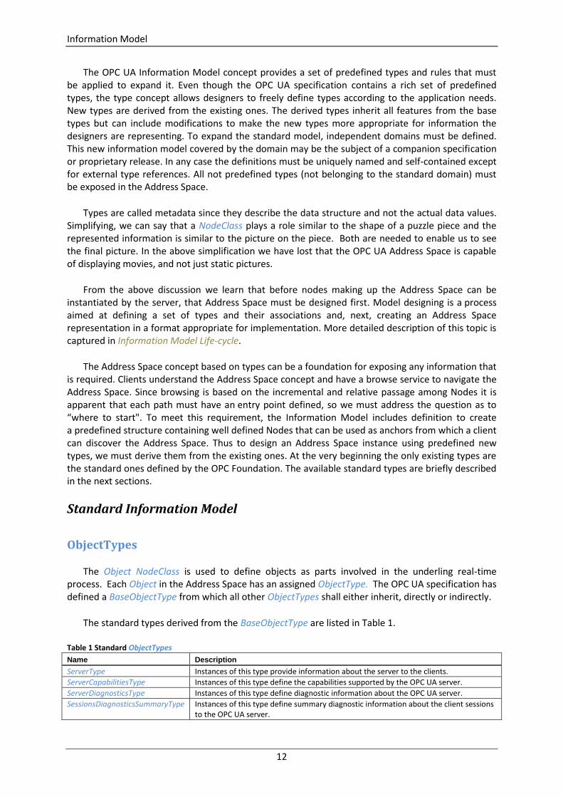
The Object NodeClass is used to define objects as parts involved in the underling real-time process. Each Object in the Address Space has an assigned ObjectType. The OPC UA specification has defined a BaseObjectType from which all other ObjectTypes shall either inherit, directly or indirectly.
The standard types derived from the BaseObjectType are listed in Table 1.
Table 1 Standard ObjectTypes
Name Description
ServerType Instances of this type provide information about the server to the clients.
ServerCapabilitiesType Instances of this type define the capabilities supported by the OPC UA server.
ServerDiagnosticsType Instances of this type define diagnostic information about the OPC UA server.
SessionsDiagnosticsSummaryType Instances of this type define summary diagnostic information about the client sessions to the OPC UA server.

Information Model
13
Name Description
SessionDiagnosticsObjectType Instances of this type define diagnostic information about the client sessions to the OPC UA server.
VendorServerInfoType Instances of this type are placeholders Object for vendor-specific information about the server. This ObjectType defines an empty ObjectType that has no components and vendors should derive from this type to expose application specific information.
ServerRedundancyType Instances of this type define the redundancy capabilities supported by the OPC UA server.
BaseEventType Instances of this type define all general characteristics of an Event. All other EventTypes derive from it.
ModellingRuleType Instances of this type provide information that identifies what happens when an object of a given type is instantiated. The instance of this type contains a property NamingRule which has the following values i.e. Optional, Mandatory, or Constraint.
FolderType Instances of this type are used to organize the Address Space into a hierarchy of nodes. They represent the root node of a subtree, and have no other semantics associated with them, except the DisplayName Attribute should imply the semantics associated with the use of it.
DataTypeEncodingType Objects of this type are used to define DataTypes of Variables NodeClass, e.g. “Default”, “UA Binary” or “XML”.
DataTypeSystemType Objects of this type are used to describe the serialization and deserialization process of the Value Attributes.
Many of these standard types are used for describing OPC UA Server functionality and to provide diagnostic information. The BaseEventType has many specialized subtypes to allow handling most common transient Events. System configuration changes, operator interaction and system errors are examples of Events. OPC UA Part 9 – Alarm and Conditions expands on this object type to define alarm and condition events.
VariableTypes
Variable NodeClass is dedicated to provide a value to the clients. To define a Variable two types must be provided (Figure 1):
1. VariableType: which describes the type of a variable. A Variable node has a HasTypeDefinition reference to its type definition (depicted as double closed and filled arrows).
2. DataType: which describes the type of the variable value. It is assigned to the DataType attribute.
Variable
VariableType
DataType
Figure 1 Variable types relationship
Information Model
14
In this section we focus on the available standard VariableTypes, but in the next one we will review standard DataTypes.
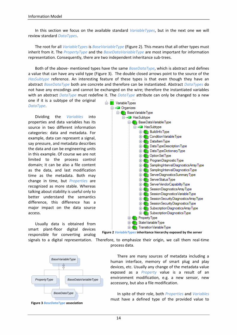
The root for all VariableTypes is BaseVariableType (Figure 2). This means that all other types must inherit from it. The PropertyType and the BaseDataVariableType are most important for information representation. Consequently, there are two independent inheritance sub-trees.
Both of the above- mentioned types have the same BaseDataType, which is abstract and defines a value that can have any valid type (Figure 3). The double closed arrows point to the source of the HasSubtype reference. An interesting feature of these types is that even though they have an abstract BaseDataType both are concrete and therefore can be instantiated. Abstract DataTypes do not have any encodings and cannot be exchanged on the wire; therefore the instantiated variables with an abstract DataType must redefine it. The DataType attribute can only be changed to a new one if it is a subtype of the original DataType.
Dividing the Variables into properties and data variables has its source in two different information categories: data and metadata. For example, data can represent a signal, say pressure, and metadata describes the data and can be engineering units in this example. Of course we are not limited to the process control domain; it can be also a file content as the data, and last modification time as the metadata. Both may change in time, but Properties are recognized as more stable. Whereas talking about stability is useful only to better understand the semantics difference, this difference has a major impact on the data source access.
Usually data is obtained from smart plant-floor digital devices responsible for converting analog signals to a digital representation. Therefore, to emphasize their origin, we call them real-time
process data.
There are many sources of metadata including a human interface, memory of smart plug and play devices, etc. Usually any change of the metadata value exposed as a Property value is a result of an environment modification, e.g. a new sensor, new accessory, but also a file modification.
In spite of their role, both Properties and Variables must have a defined type of the provided value to
Figure 2 VariableTypes inheritance hierarchy exposed by the server
BaseVariableType
PropertyType BaseDataVariableType
BaseDataType
Figure 3 BaseDataType association
Information Model
15
Figure 5 ServerStatusType structure
allow clients to interpret a stream of bits sent on the wire and obtained by a client from the server.
It is worth stressing that, according to the specification, the inheritance chain is broken for the Properties; it means that the PropertyType must not have subtypes. Additionally, it is not permitted to have a Property as source of the HierarchicalReferences type or any type inherited from it. In other words properties cannot be complex. To prevent recursion, Properties are also not allowed to have Properties defined for them. Additionally, a node and all its Properties shall always reside in the same server.
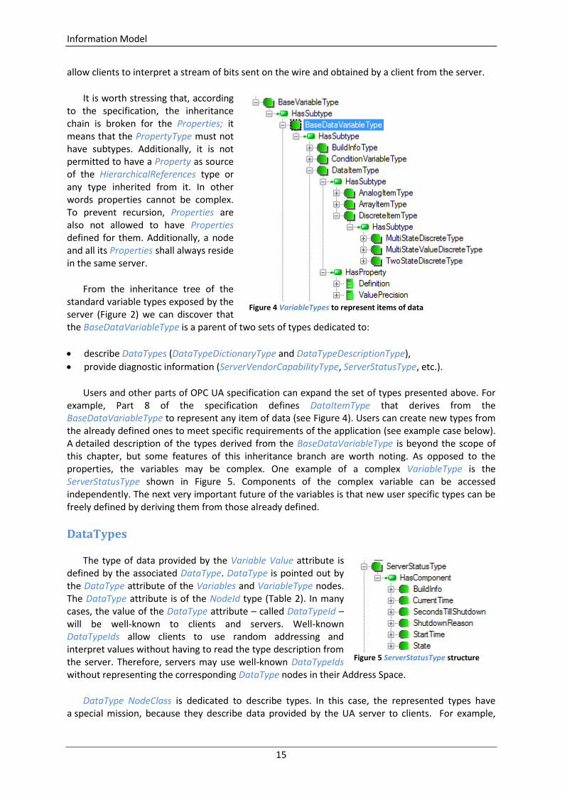
From the inheritance tree of the standard variable types exposed by the server (Figure 2) we can discover that the BaseDataVariableType is a parent of two sets of types dedicated to:
describe DataTypes (DataTypeDictionaryType and DataTypeDescriptionType),
provide diagnostic information (ServerVendorCapabilityType, ServerStatusType, etc.).
Users and other parts of OPC UA specification can expand the set of types presented above. For example, Part 8 of the specification defines DataItemType that derives from the BaseDataVariableType to represent any item of data (see Figure 4). Users can create new types from the already defined ones to meet specific requirements of the application (see example case below). A detailed description of the types derived from the BaseDataVariableType is beyond the scope of this chapter, but some features of this inheritance branch are worth noting. As opposed to the properties, the variables may be complex. One example of a complex VariableType is the ServerStatusType shown in Figure 5. Components of the complex variable can be accessed independently. The next very important future of the variables is that new user specific types can be freely defined by deriving them from those already defined.
DataTypes
The type of data provided by the Variable Value attribute is defined by the associated DataType. DataType is pointed out by the DataType attribute of the Variables and VariableType nodes. The DataType attribute is of the NodeId type (Table 2). In many cases, the value of the DataType attribute – called DataTypeId – will be well-known to clients and servers. Well-known DataTypeIds allow clients to use random addressing and interpret values without having to read the type description from the server. Therefore, servers may use well-known DataTypeIds without representing the corresponding DataType nodes in their Address Space.
DataType NodeClass is dedicated to describe types. In this case, the represented types have a special mission, because they describe data provided by the UA server to clients. For example,
Figure 4 VariableTypes to represent items of data
Information Model
16
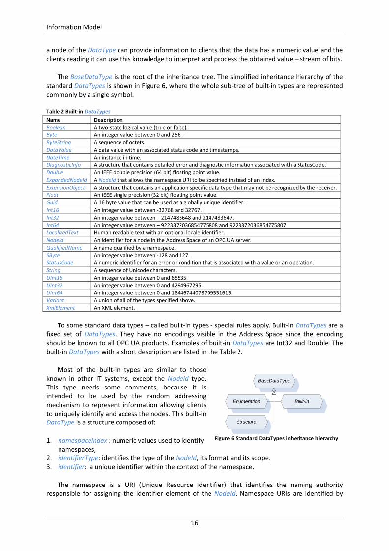
a node of the DataType can provide information to clients that the data has a numeric value and the clients reading it can use this knowledge to interpret and process the obtained value – stream of bits.
The BaseDataType is the root of the inheritance tree. The simplified inheritance hierarchy of the standard DataTypes is shown in Figure 6, where the whole sub-tree of built-in types are represented commonly by a single symbol.
Table 2 Built-in DataTypes
Name Description
Boolean A two-state logical value (true or false).
Byte An integer value between 0 and 256.
ByteString A sequence of octets.
DataValue A data value with an associated status code and timestamps.
DateTime An instance in time.
DiagnosticInfo A structure that contains detailed error and diagnostic information associated with a StatusCode.
Double An IEEE double precision (64 bit) floating point value.
ExpandedNodeId A NodeId that allows the namespace URI to be specified instead of an index.
ExtensionObject A structure that contains an application specific data type that may not be recognized by the receiver.
Float An IEEE single precision (32 bit) floating point value.
Guid A 16 byte value that can be used as a globally unique identifier.
Int16 An integer value between -32768 and 32767.
Int32 An integer value between – 2147483648 and 2147483647.
Int64 An integer value between – 9223372036854775808 and 9223372036854775807
LocalizedText Human readable text with an optional locale identifier.
NodeId An identifier for a node in the Address Space of an OPC UA server.
QualifiedName A name qualified by a namespace.
SByte An integer value between -128 and 127.
StatusCode A numeric identifier for an error or condition that is associated with a value or an operation.
String A sequence of Unicode characters.
UInt16 An integer value between 0 and 65535.
UInt32 An integer value between 0 and 4294967295.
UInt64 An integer value between 0 and 18446744073709551615.
Variant A union of all of the types specified above.
XmlElement An XML element.
To some standard data types – called built-in types - special rules apply. Built-in DataTypes are a fixed set of DataTypes. They have no encodings visible in the Address Space since the encoding should be known to all OPC UA products. Examples of built-in DataTypes are Int32 and Double. The built-in DataTypes with a short description are listed in the Table 2.
Most of the built-in types are similar to those known in other IT systems, except the NodeId type. This type needs some comments, because it is intended to be used by the random addressing mechanism to represent information allowing clients to uniquely identify and access the nodes. This built-in DataType is a structure composed of:
1. namespaceIndex : numeric values used to identify namespaces,
2. identifierType: identifies the type of the NodeId, its format and its scope, 3. identifier: a unique identifier within the context of the namespace.
The namespace is a URI (Unique Resource Identifier) that identifies the naming authority responsible for assigning the identifier element of the NodeId. Namespace URIs are identified by
BaseDataType
Built-inEnumeration
Structure
Figure 6 Standard DataTypes inheritance hierarchy

Information Model
17
numeric values in OPC UA Services to permit a more efficient transfer and processing (e.g. table lookups).
Depending on the application requirements, the identifierType field may have the following values:
NUMERIC: numeric
STRING: text string
GUID: Globally Unique Identifier
OPAQUE: namespace specific format
Enumeration (Figure 6) is the next standard DataType derived directly from BaseDataType, that needs some comments. It is to be used to represent a limited set of simple information entities. Therefore it is a simple and abstract type. All enumerations, like NodeClass, have to inherit from it. All types inheriting from the Enumeration have a special processing for the encoding.
Process data could be complex. Structure (Figure 6) is an abstract DataType defined as the base for all structured types. All DataTypes inheriting from it have a special processing for the encoding. All complex data, if not defined explicitly as primitive in the specification, are created by defining of new types derived from the Structure.
When complex data structures should be made available to the client there are basically three different approaches:
Create several simple Variables using simple DataTypes reflecting parts of the structure and map the data structure using these Variables as Object or Variable components.
Create a complex DataType and a simple Variable using DataType derived from Structure.
Create a complex DataType and a complex Variable using this DataType and also exposing the complex data structure as Variables of the complex Variable using simple DataTypes.
An example of the first scenario is shown in Figure 5 where a variable of the ServerStatusType has components of a simple DataType. Advantages of this approach:
the complex structure of data is visible in the Address Space,
a generic client can easily access the data without any knowledge of user-defined DataTypes,
the client can access individual parts of complex data.
Disadvantages of the first approach are that accessing individual data does not provide any transactional context; and for a specific client the server first has to convert data and the client has to convert data, again, to get the data structure the underlying system provides.
An example of the second scenario is shown in Figure 7. Here, the same information as previously is available as a complex DataType of the ServerStatusDataType that inherits from the Structure. The
ServerStatusType
ServerStatusDataType
Structure
StartTime
CurrentTime
BuildInfo
SecondsTillShutdown
ShutdownReason
State
Figure 7 ServerStatusDataType Structure
Information Model
18
ServerStatusDataType arranges the server status data as a collection of fields. Advantages of this approach:
data is accessed in a transaction context,
the complex DataType can be constructed in a way that the server does not have to convert data and can pass it directly to the specific client that can directly use it.
Disadvantages are that the generic client might not be able to access and interpret the data or it has the burden to read the DataTypeDescription to interpret the data. The data structure is not visible in the Address Space; additional Properties describing the data structure cannot be added to the DataType. Individual parts of data cannot be read without accessing the whole data structure.
The third approach combines both other approaches. The specific client can, therefore, access data in its native format in a transactional context, whereas the generic client can access the simple DataTypes of the components of the complex Variable. The disadvantage is that the server has to be able to provide the native format and also interpret it to be able to provide information in simple DataTypes. In some SDK’s support for this mapping is provided automatically; for example the OPC .NET SDK will provide this mapping as part of its code generator for user defined types.
When a transactional context is needed or the client should be able to get a large amount of data instead of subscribing to several individual values, the third approach is suitable. However, the server might not always have the knowledge how to interpret complex data or be able to have predefined structures for the complex data of the underlying system and it, therefore, has to use the second approach just passing data to the specific client who is able to interpret the data.
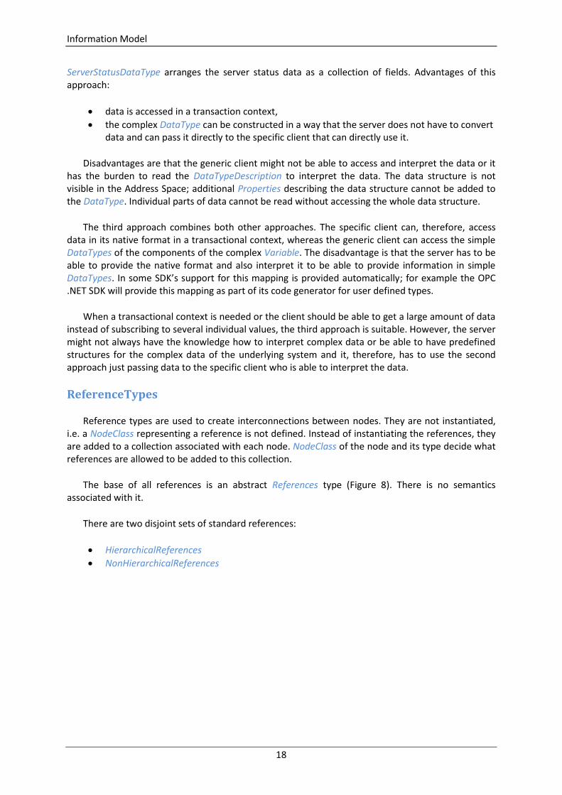
ReferenceTypes
Reference types are used to create interconnections between nodes. They are not instantiated, i.e. a NodeClass representing a reference is not defined. Instead of instantiating the references, they are added to a collection associated with each node. NodeClass of the node and its type decide what references are allowed to be added to this collection.
The base of all references is an abstract References type (Figure 8). There is no semantics associated with it.
There are two disjoint sets of standard references:
HierarchicalReferences
NonHierarchicalReferences
Information Model
19
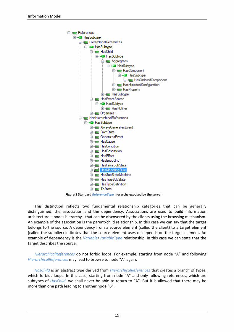
This distinction reflects two fundamental relationship categories that can be generally distinguished: the association and the dependency. Associations are used to build information architecture – nodes hierarchy - that can be discovered by the clients using the browsing mechanism. An example of the association is the parent/child relationship. In this case we can say that the target belongs to the source. A dependency from a source element (called the client) to a target element (called the supplier) indicates that the source element uses or depends on the target element. An example of dependency is the Variable/VariableType relationship. In this case we can state that the target describes the source.
HierarchicalReferences do not forbid loops. For example, starting from node “A” and following HierarchicalReferences may lead to browse to node “A” again.
HasChild is an abstract type derived from HierarchicalReferences that creates a branch of types, which forbids loops. In this case, starting from node “A” and only following references, which are subtypes of HasChild, we shall never be able to return to “A”. But it is allowed that there may be more than one path leading to another node “B”.
Figure 8 Standard ReferenceType hierarchy exposed by the server
Information Model
20
The HasChild branch contains HasComponent and HasProperty. Both are derived from the Aggregates type and used to reflect the parent – child relationship. There is also HasSubtype on this branch, but in this case it is used to expose the inheritance hierarchy.
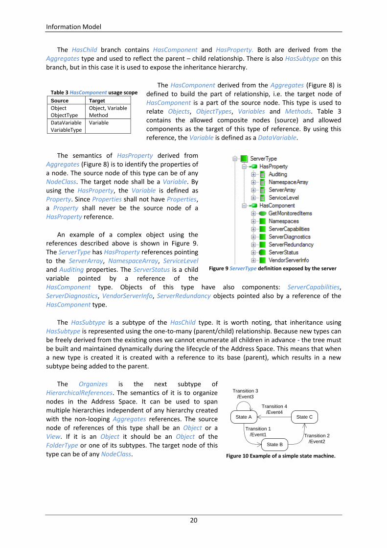
The HasComponent derived from the Aggregates (Figure 8) is defined to build the part of relationship, i.e. the target node of HasComponent is a part of the source node. This type is used to relate Objects, ObjectTypes, Variables and Methods. Table 3 contains the allowed composite nodes (source) and allowed components as the target of this type of reference. By using this reference, the Variable is defined as a DataVariable.
The semantics of HasProperty derived from Aggregates (Figure 8) is to identify the properties of a node. The source node of this type can be of any NodeClass. The target node shall be a Variable. By using the HasProperty, the Variable is defined as Property. Since Properties shall not have Properties, a Property shall never be the source node of a HasProperty reference.
An example of a complex object using the references described above is shown in Figure 9. The ServerType has HasProperty references pointing to the ServerArray, NamespaceArray, ServiceLevel and Auditing properties. The ServerStatus is a child variable pointed by a reference of the HasComponent type. Objects of this type have also components: ServerCapabilities, ServerDiagnostics, VendorServerInfo, ServerRedundancy objects pointed also by a reference of the HasComponent type.
The HasSubtype is a subtype of the HasChild type. It is worth noting, that inheritance using HasSubtype is represented using the one-to-many (parent/child) relationship. Because new types can be freely derived from the existing ones we cannot enumerate all children in advance - the tree must be built and maintained dynamically during the lifecycle of the Address Space. This means that when a new type is created it is created with a reference to its base (parent), which results in a new subtype being added to the parent.
The Organizes is the next subtype of HierarchicalReferences. The semantics of it is to organize nodes in the Address Space. It can be used to span multiple hierarchies independent of any hierarchy created with the non-looping Aggregates references. The source node of references of this type shall be an Object or a View. If it is an Object it should be an Object of the FolderType or one of its subtypes. The target node of this type can be of any NodeClass.
Table 3 HasComponent usage scope
Source Target
Object ObjectType
Object, Variable Method
DataVariable VariableType
Variable
Figure 9 ServerType definition exposed by the server
State A State C
State B
Transition 1
/Event1 Transition 2
/Event2
Transition 4
/Event4
Transition 3
/Event3
Figure 10 Example of a simple state machine.

Information Model
21
State machines
The information model provides constructs that can be used to model discrete object behavior in terms of the states an object can reside in and the transitions that can happen between those states. State machines (see example in Figure 10) are built as complex objects using dedicated ObjectTypes, VariableTypes and ReferenceTypes, whose behavior is governed by the rules that must be strictly observed.
A state is a condition in which an object can be at some point during its lifetime, for some finite amount of time. A transition is a change of an object from one state (the source state) to another (the target state). The transition is triggered ("fires") when an event of interest – cause - to a given object occurs. According to the information model concept, causes are represented in the form of Methods that have to be called, but a vendor can define other items or have them be internal (i.e. nothing is listed causing the transition). There may also be an action associated with a triggered transition. This action called an “effect” is executed unconditionally before the object enters the
target state. Effects are Events that are generated.
The simplified state machine model described above can be freely expanded to provide more complex functionality like sub-machines, parallel states, forks and joins, history states, choices and junctions, etc.
State machines are represented in the Address Space as an object of a type derived from the StateMachineType that defines a single Variable of the StateVariableType, which represents the current state of the machine. An instance of the StateMachineType shall generate an event whenever a state change occurs. Transitions are represented as objects of the TransitionType. Each valid transition shall have exactly one FromState reference and exactly one ToState reference, each pointing to an object of the StateType.
Using the above terminology we can represent any state machine from Figure 10 as a diagram shown in Figure 11. For this diagram it is assumed that MyStateMachineType is derived directly or
MyStateMachineType
StateA
StateB
StateC
Transition 3FromState
ToState
Transition 1FromState
ToState
Transition 2
FromState
ToState
Transition 4FromState
ToState
Method 3
Method 1
Method 2
Method 4
HasCause
HasCause
HasCause
HasCause
Event3Type
Event2Type
Event4Type
Event1Type
GenerateEvent
GenerateEvent
GenerateEvent
GenerateEvent
HasEffect
HasEffect
HasEffect
HasEffect
Figure 11 Representation of the example state machine.
Information Models Creation
22
indirectly from the StateMachineType. All states, transitions and methods are components of this type.
Information Models Creation
Methodology
OPC UA specification provides a standard Information Model domain, which contains a set of predefined types and instances. This domain may be extended by designing a new one. Even though the standard Information Model contains a rich set of predefined types, the type concept allows designers to freely define types according to the application needs. New types are derived from the existing ones. The derived types inherit all features of the base types but can include modifications to make the new types more appropriate for information to be represented. This new information model covered by the domain may be the subject of a companion specification or proprietary solution. In any case new definitions must be uniquely named and self-contained except for external type references. All not predefined types (not belonging to the standard domain) must be exposed in the Address Space by the server.
The model design engineering is an emerging discipline in which engineers develop new models with a primary emphasis on convergence between information describing the state and behavior of a selected real-time process and simplified representation of the process by process data. The data is formally described in terms of types. Generally speaking there are two approaches possible:
Design a custom model that meets requirements of a proprietary process.
Adopt an existing model released as a companion specification to meet the requirements of a proprietary process.
To improve performance of independent model developments as a result of reusability and, what is more important, to promote unification of results there are many activities aimed at designing models for selected processes. The unification enables vendors to commence independent developments of selected application aware products. In this section a case studies illustrating both approaches is presented.
Custom Models - Boiler
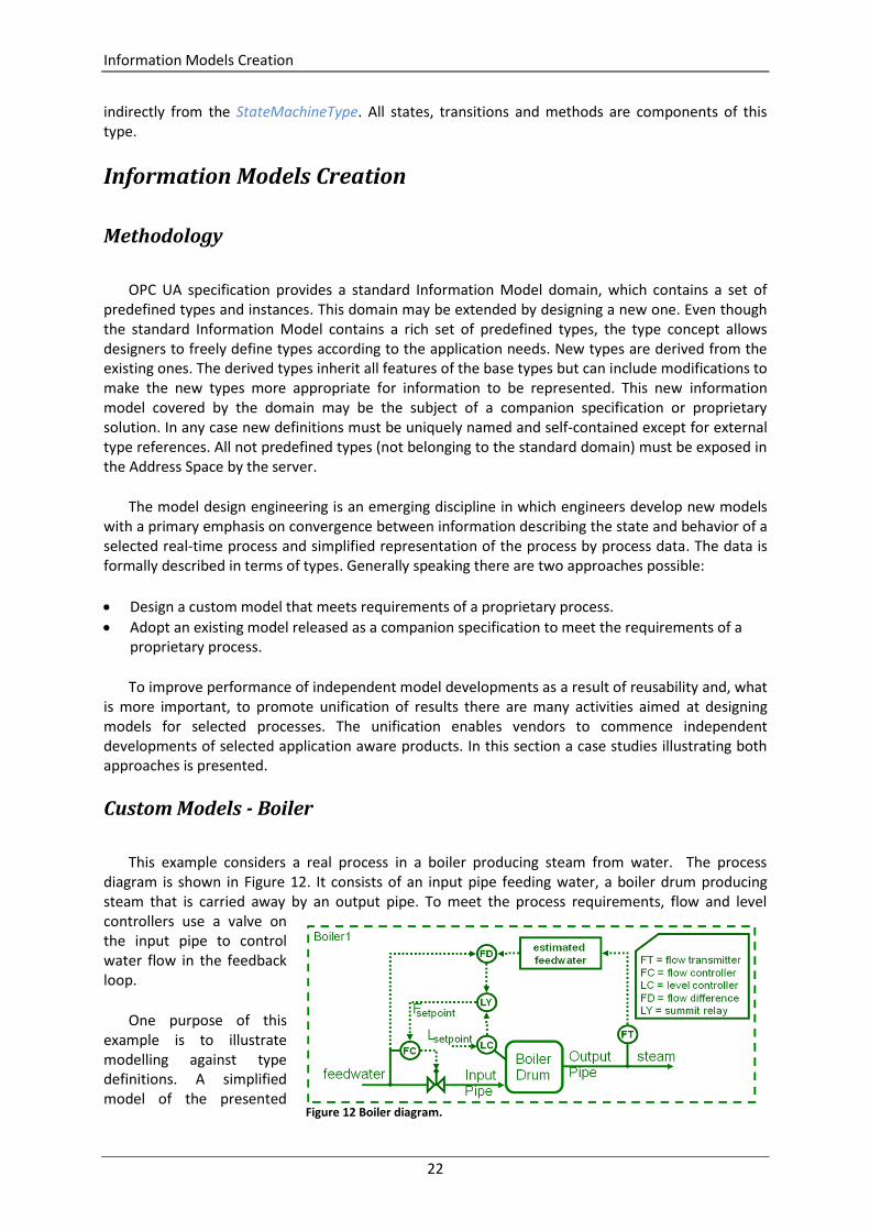
This example considers a real process in a boiler producing steam from water. The process diagram is shown in Figure 12. It consists of an input pipe feeding water, a boiler drum producing steam that is carried away by an output pipe. To meet the process requirements, flow and level controllers use a valve on the input pipe to control water flow in the feedback loop.
One purpose of this example is to illustrate modelling against type definitions. A simplified model of the presented
Figure 12 Boiler diagram.
Information Models Creation
23
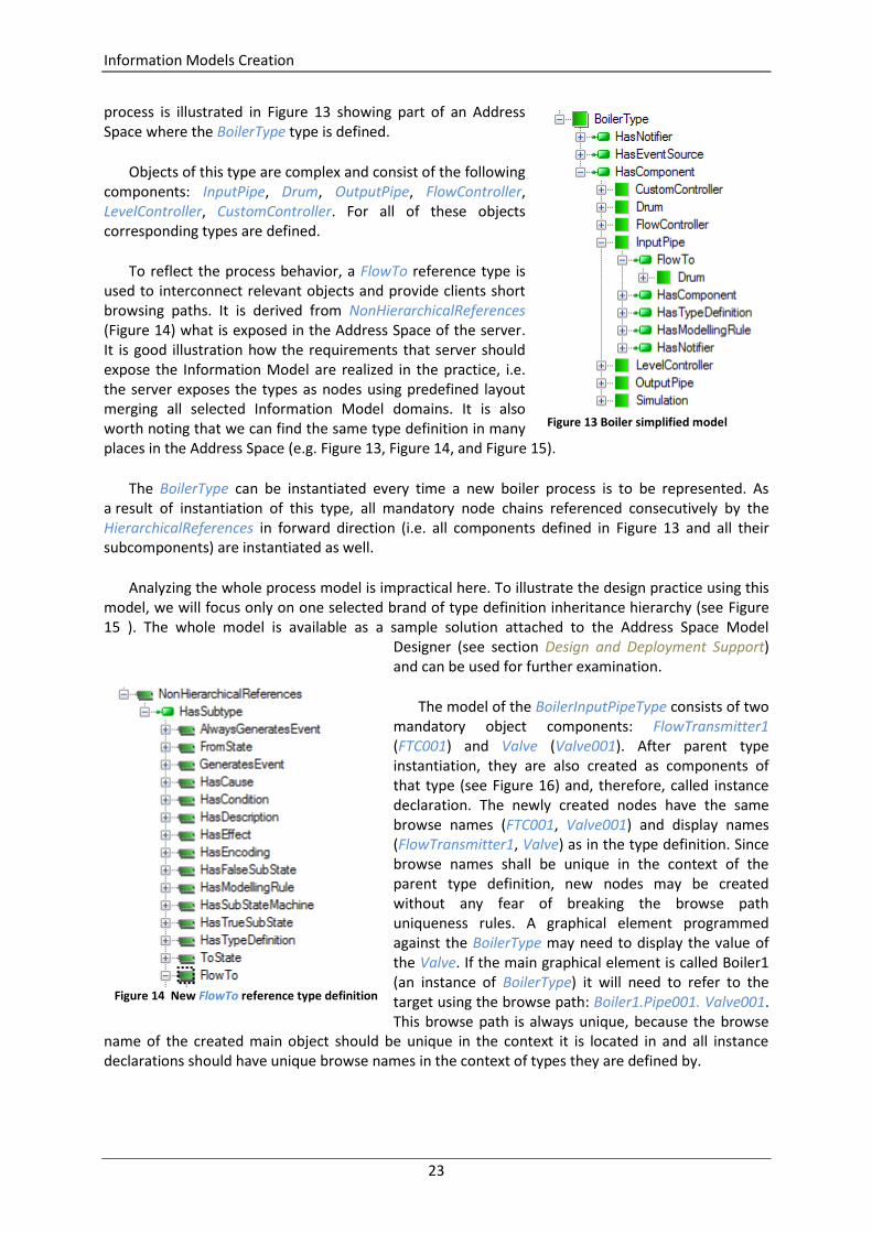
process is illustrated in Figure 13 showing part of an Address Space where the BoilerType type is defined.
Objects of this type are complex and consist of the following components: InputPipe, Drum, OutputPipe, FlowController, LevelController, CustomController. For all of these objects corresponding types are defined.
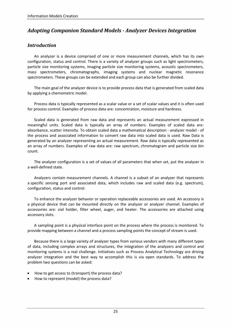
To reflect the process behavior, a FlowTo reference type is used to interconnect relevant objects and provide clients short browsing paths. It is derived from NonHierarchicalReferences (Figure 14) what is exposed in the Address Space of the server. It is good illustration how the requirements that server should expose the Information Model are realized in the practice, i.e. the server exposes the types as nodes using predefined layout merging all selected Information Model domains. It is also worth noting that we can find the same type definition in many places in the Address Space (e.g. Figure 13, Figure 14, and Figure 15).
The BoilerType can be instantiated every time a new boiler process is to be represented. As a result of instantiation of this type, all mandatory node chains referenced consecutively by the HierarchicalReferences in forward direction (i.e. all components defined in Figure 13 and all their subcomponents) are instantiated as well.
Analyzing the whole process model is impractical here. To illustrate the design practice using this model, we will focus only on one selected brand of type definition inheritance hierarchy (see Figure 15 ). The whole model is available as a sample solution attached to the Address Space Model
Designer (see section Design and Deployment Support) and can be used for further examination.
The model of the BoilerInputPipeType consists of two mandatory object components: FlowTransmitter1 (FTC001) and Valve (Valve001). After parent type instantiation, they are also created as components of that type (see Figure 16) and, therefore, called instance declaration. The newly created nodes have the same browse names (FTC001, Valve001) and display names (FlowTransmitter1, Valve) as in the type definition. Since browse names shall be unique in the context of the parent type definition, new nodes may be created without any fear of breaking the browse path uniqueness rules. A graphical element programmed against the BoilerType may need to display the value of the Valve. If the main graphical element is called Boiler1 (an instance of BoilerType) it will need to refer to the target using the browse path: Boiler1.Pipe001. Valve001. This browse path is always unique, because the browse
name of the created main object should be unique in the context it is located in and all instance declarations should have unique browse names in the context of types they are defined by.
Figure 13 Boiler simplified model
Figure 14 New FlowTo reference type definition

Information Models Creation
24
FlowTransmiter1 is of FlowTransmitterType type, which indirectly inherits from GenericSensorType, based finally on the standard BaseObjectType. GenericSensorType has a component – an Output variable of the standard AnalogItemType, which has three properties: EURange, InstrumentRange and EngineeringUnits, but only EURange is mandatory. InstrumentRange and EngineeringUnits are optional, therefore should be created if needed. In the case of optional instance declaration, clients are responsible for examining the exposed Address Space to check if the predefined nodes are instantiated.
After instantiation of the BoilerType and adding reference to it in the Objects.Boilers folder, we obtain the Address Space presented in Figure 16 exposed by the server to clients. It should be noted that in Figure 16 both objects, FlowTransmitter1 and Valve, have names other than in the definition. It is because each node in the Address Space has DisplayName attribute that contains the localized
name of the node. Clients should use this attribute if they want to display the node name to the user. They should not use the browse name for this purpose. In this example only mandatory nodes have been instantiated.
Figure 15 Model of the BoilerInputPipeType inheritance hierarchy
Figure 16 Boiler Object exposed by the server
Information Models Creation
25
Adopting Companion Standard Models - Analyzer Devices Integration
Introduction
An analyzer is a device comprised of one or more measurement channels, which has its own configuration, status and control. There is a variety of analyzer groups such as light spectrometers, particle size monitoring systems, imaging particle size monitoring systems, acoustic spectrometers, mass spectrometers, chromatographs, imaging systems and nuclear magnetic resonance spectrometers. These groups can be extended and each group can also be further divided.
The main goal of the analyzer device is to provide process data that is generated from scaled data by applying a chemometric model.
Process data is typically represented as a scalar value or a set of scalar values and it is often used for process control. Examples of process data are: concentration, moisture and hardness.
Scaled data is generated from raw data and represents an actual measurement expressed in meaningful units. Scaled data is typically an array of numbers. Examples of scaled data are: absorbance, scatter intensity. To obtain scaled data a mathematical description - analyzer model - of the process and associated information to convert raw data into scaled data is used. Raw Data is generated by an analyzer representing an actual measurement. Raw data is typically represented as an array of numbers. Examples of raw data are: raw spectrum, chromatogram and particle size bin count.
The analyzer configuration is a set of values of all parameters that when set, put the analyzer in a well-defined state.
Analyzers contain measurement channels. A channel is a subset of an analyzer that represents a specific sensing port and associated data, which includes raw and scaled data (e.g. spectrum), configuration, status and control.
To enhance the analyzer behavior or operation replaceable accessories are used. An accessory is a physical device that can be mounted directly on the analyzer or analyzer channel. Examples of accessories are: vial holder, filter wheel, auger, and heater. The accessories are attached using accessory slots.
A sampling point is a physical interface point on the process where the process is monitored. To provide mapping between a channel and a process sampling points the concept of stream is used.
Because there is a large variety of analyzer types from various vendors with many different types of data, including complex arrays and structures, the integration of the analyzers and control and monitoring systems is a real challenge. Initiatives such as Process Analytical Technology are driving analyzer integration and the best way to accomplish this is via open standards. To address the problem two questions can be asked:
How to get access to (transport) the process data?
How to represent (model) the process data?
Information Models Creation
26
To answer the first question we need a universally accepted, platform-neutral communication standard that allows also addressing the second question, i.e. designing an appropriate information model. OPC Unified Architecture technology meets all the requirements, because:
It is a platform neutral standard allowing for easy embedded implementation.
It is designed to support complex data types and object models.
It is designed to achieve high speed data transfers using efficient binary protocols.
It has broad industry support beyond just process automation and is being used in support of other industry standards such as S95, S88, EDDL, MIMOSA, OAGiS.
Companion Specification - Information Model for Analyzers
In 2008 the OPC Foundation announced support for Analyzer Devices Integration into the OPC Unified Architecture and created a working group composed of end-users and vendors with the main goal of developing a common method for data exchange and an analyzer data model for process and laboratory analyzers. In 2009 the OPC Unified Architecture Companion Specification for Analyzer Devices was released [8]. To prove the concept a reference implementation was developed containing an ADI compliant server and simple client using the Software Development Kid released by the OPC Foundation.
The model described in the specification [8] is intended to provide a unified view of analyzers irrespective of the underlying device. This Information Model is also referred to as the ADI Information Model. As it was mentioned, analyzers can be further refined into various groups, but the specification defines an Information Model that can be applied to all the groups of analyzers.
The ADI Information Model is located above the DI Information Model [9]. It means that the ADI model refers to definitions provided by the DI model, but the reverse is not true. To expand the ADI Information Model, the next layers shall be provided.
Analyzing in detail the whole ADI Information Model is impractical here. Hence, the discussion below will be focused only on selected types defined in this specification to illustrate the design practice of the model adoption.
The object model that describes analyzers is separated into definitions of the types representing the main parts of the device, namely: AnalyserDeviceType, AnalyserChannelType, StreamType, AccessoryType and AccessorySlotType.
In general terms AnalyserDeviceType represents the instrument as a whole. Each object of the AnalyserDeviceType has at least one component of the AnalyserChannelType and may have components of the AccessorySlotType. Similarly, each object of AnalyserChannelType may have AccessorySlotType components.
AnalyserDeviceType is an abstract type which shall be subtyped for different types of analyzer devices. In the specification [8] there are defined the following subtypes of the AnalyserDeviceType: SpectrometerDeviceType, AcousticSpectrometerDeviceType, MassSpectrometerDeviceType, ParticleSizeMonitorDeviceType, ChromatographDeviceType, NMRDeviceType. Each of these types may be further subtyped by device vendors to converge the Information Model and the underlying process.
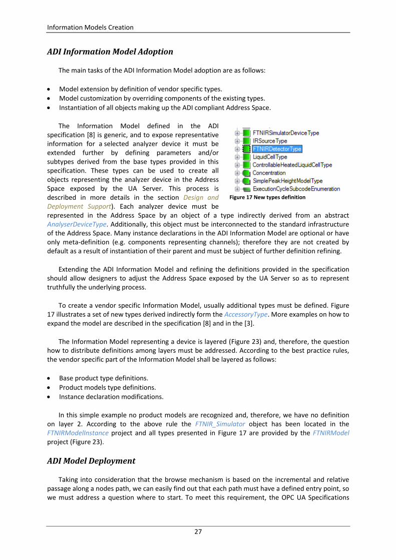
Information Models Creation
27
ADI Information Model Adoption
The main tasks of the ADI Information Model adoption are as follows:
Model extension by definition of vendor specific types.
Model customization by overriding components of the existing types.
Instantiation of all objects making up the ADI compliant Address Space.
The Information Model defined in the ADI specification [8] is generic, and to expose representative information for a selected analyzer device it must be extended further by defining parameters and/or subtypes derived from the base types provided in this specification. These types can be used to create all objects representing the analyzer device in the Address Space exposed by the UA Server. This process is described in more details in the section Design and Deployment Support). Each analyzer device must be represented in the Address Space by an object of a type indirectly derived from an abstract AnalyserDeviceType. Additionally, this object must be interconnected to the standard infrastructure of the Address Space. Many instance declarations in the ADI Information Model are optional or have only meta-definition (e.g. components representing channels); therefore they are not created by default as a result of instantiation of their parent and must be subject of further definition refining.
Extending the ADI Information Model and refining the definitions provided in the specification should allow designers to adjust the Address Space exposed by the UA Server so as to represent truthfully the underlying process.
To create a vendor specific Information Model, usually additional types must be defined. Figure 17 illustrates a set of new types derived indirectly form the AccessoryType. More examples on how to expand the model are described in the specification [8] and in the [3].
The Information Model representing a device is layered (Figure 23) and, therefore, the question how to distribute definitions among layers must be addressed. According to the best practice rules, the vendor specific part of the Information Model shall be layered as follows:
Base product type definitions.
Product models type definitions.
Instance declaration modifications.
In this simple example no product models are recognized and, therefore, we have no definition on layer 2. According to the above rule the FTNIR_Simulator object has been located in the FTNIRModelInstance project and all types presented in Figure 17 are provided by the FTNIRModel project (Figure 23).
ADI Model Deployment
Taking into consideration that the browse mechanism is based on the incremental and relative passage along a nodes path, we can easily find out that each path must have a defined entry point, so we must address a question where to start. To meet this requirement, the OPC UA Specifications
Figure 17 New types definition
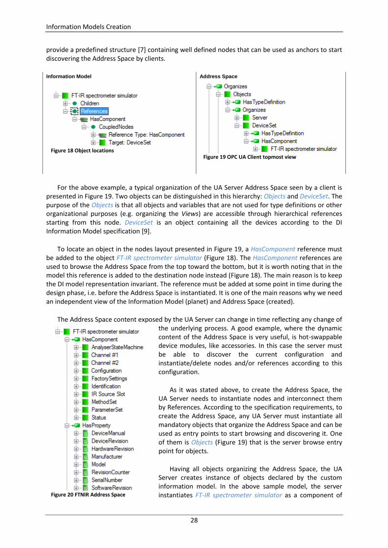
Information Models Creation
28
provide a predefined structure [7] containing well defined nodes that can be used as anchors to start discovering the Address Space by clients.
Information Model Address Space
For the above example, a typical organization of the UA Server Address Space seen by a client is presented in Figure 19. Two objects can be distinguished in this hierarchy: Objects and DeviceSet. The purpose of the Objects is that all objects and variables that are not used for type definitions or other organizational purposes (e.g. organizing the Views) are accessible through hierarchical references starting from this node. DeviceSet is an object containing all the devices according to the DI Information Model specification [9].
To locate an object in the nodes layout presented in Figure 19, a HasComponent reference must be added to the object FT-IR spectrometer simulator (Figure 18). The HasComponent references are used to browse the Address Space from the top toward the bottom, but it is worth noting that in the model this reference is added to the destination node instead (Figure 18). The main reason is to keep the DI model representation invariant. The reference must be added at some point in time during the design phase, i.e. before the Address Space is instantiated. It is one of the main reasons why we need an independent view of the Information Model (planet) and Address Space (created).
The Address Space content exposed by the UA Server can change in time reflecting any change of the underlying process. A good example, where the dynamic content of the Address Space is very useful, is hot-swappable device modules, like accessories. In this case the server must be able to discover the current configuration and instantiate/delete nodes and/or references according to this configuration.
As it was stated above, to create the Address Space, the UA Server needs to instantiate nodes and interconnect them by References. According to the specification requirements, to create the Address Space, any UA Server must instantiate all mandatory objects that organize the Address Space and can be used as entry points to start browsing and discovering it. One of them is Objects (Figure 19) that is the server browse entry point for objects.
Having all objects organizing the Address Space, the UA Server creates instance of objects declared by the custom information model. In the above sample model, the server instantiates FT-IR spectrometer simulator as a component of
Figure 20 FTNIR Address Space
Figure 19 OPC UA Client topmost view
Figure 18 Object locations
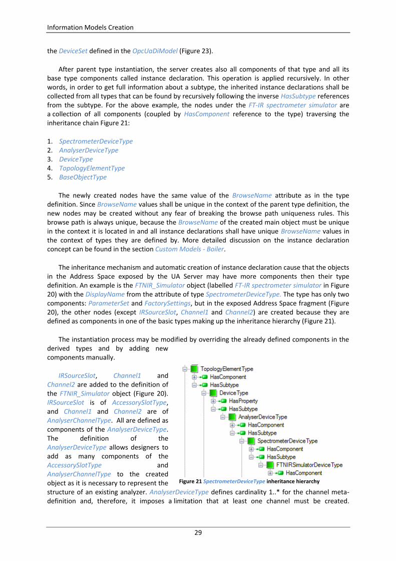
Information Models Creation
29
the DeviceSet defined in the OpcUaDiModel (Figure 23).
After parent type instantiation, the server creates also all components of that type and all its base type components called instance declaration. This operation is applied recursively. In other words, in order to get full information about a subtype, the inherited instance declarations shall be collected from all types that can be found by recursively following the inverse HasSubtype references from the subtype. For the above example, the nodes under the FT-IR spectrometer simulator are a collection of all components (coupled by HasComponent reference to the type) traversing the inheritance chain Figure 21:
1. SpectrometerDeviceType 2. AnalyserDeviceType 3. DeviceType 4. TopologyElementType 5. BaseObjectType
The newly created nodes have the same value of the BrowseName attribute as in the type definition. Since BrowseName values shall be unique in the context of the parent type definition, the new nodes may be created without any fear of breaking the browse path uniqueness rules. This browse path is always unique, because the BrowseName of the created main object must be unique in the context it is located in and all instance declarations shall have unique BrowseName values in the context of types they are defined by. More detailed discussion on the instance declaration concept can be found in the section Custom Models - Boiler.
The inheritance mechanism and automatic creation of instance declaration cause that the objects in the Address Space exposed by the UA Server may have more components then their type definition. An example is the FTNIR_Simulator object (labelled FT-IR spectrometer simulator in Figure 20) with the DisplayName from the attribute of type SpectrometerDeviceType. The type has only two components: ParameterSet and FactorySettings, but in the exposed Address Space fragment (Figure 20), the other nodes (except IRSourceSlot, Channel1 and Channel2) are created because they are defined as components in one of the basic types making up the inheritance hierarchy (Figure 21).
The instantiation process may be modified by overriding the already defined components in the derived types and by adding new components manually.
IRSourceSlot, Channel1 and Channel2 are added to the definition of the FTNIR_Simulator object (Figure 20). IRSourceSlot is of AccessorySlotType, and Channel1 and Channel2 are of AnalyserChannelType. All are defined as components of the AnalyserDeviceType. The definition of the AnalyserDeviceType allows designers to add as many components of the AccessorySlotType and AnalyserChannelType to the created object as it is necessary to represent the structure of an existing analyzer. AnalyserDeviceType defines cardinality 1..* for the channel meta-definition and, therefore, it imposes a limitation that at least one channel must be created.
Figure 21 SpectrometerDeviceType inheritance hierarchy

Information Model Life-cycle
30
Components of the AnalyserChannelType are an example where the basic ADI Information Model must be customized to converge the Address Space with the represented underlying environment.
The properties SerialNumber, RevisionCounter, Manufacturer, Model, DeviceManual, DeviceRevision, SoftwareRevision and HardwareRevision (Figure 20) are inherited from the DeviceType defined by the DI Information Model. Values of these properties can be defined as default values in the model or provided by the equipment at runtime.
A very important AnalyserStateMachine component of the FT-IR spectrometer simulator is inherited from AnalyserDeviceType. AnalyserStateMachine is an object that represents behavior of the analyzer device using the state machine concept. This construct can be used to model discrete object behavior in terms of the states an object can reside in and transitions that can happen between those states. State machines are built as complex objects using dedicated ObjectTypes, VariableTypes and ReferenceTypes, whose semantics is governed by the rules that must be strictly observed. A state is a condition in which an object can be at some point during its lifetime, for some finite amount of time. A transition is a change of an object from one state (the source state) to another (the target state). The transition is triggered ("fires") when an event of interest - cause - to a given object occurs. According to the Information Model concept, causes are represented in the form of Methods that shall be called, but a vendor can define other items or have them be internal (i.e. nothing is listed causing the transition). There may also be an action associated with a triggered transition. This action is executed unconditionally before the object enters the target state and effects in the form of Events that are generated.
The AnalyserDeviceType is also a source of definition of the Methods exposed by the UA Server (Figure 20). All the methods are collected as components of the MethodSet object.
Information Model Life-cycle
The OPC Unified Architecture (UA) is a standard that allows servers to provide real-time process data, environment metadata and even non-process data to clients, in a unique and platform-independent way. To meet this objective, at runtime each server instantiates and maintains the Address Space that is a collection of data to be exposed to clients. The OPC Unified Architecture Address Space consists of nodes and References. The main role of the nodes is to expose the underlying process state as a structured piece of information.
At runtime typical implementation architecture consists of OPC UA Clients, which are connected to an OPC UA Server. The server exposes process data in the context of the Address Space instantiated in compliance with the selected Information Model domains, for example using the ADI Information Model domain presented in the section Adopting Companion Standard Models - Analyzer Devices Integration. In a typical architecture (Figure 22) exposing the process data in the context of Address Space means that information produced by the Real-time Process is gathered by the Process Link as process data and assigned to Variables nodes residing in the Address Space. Next, process data can be accessed and processed by a generic client using Services. In a production environment the Information Model types may be used to offer additional functions, namely customized control panels, dedicated data visualization panes or predefined structure of the database tables. Types knowledge also simplifies the configuration of clients, because all of the items composing the complex process information can be accessed automatically.
Information Model Life-cycle
31
To implement the Address Space concept, two questions must be addressed:
How to create and maintain it?
How to bind the Variable nodes with the real-time process data sources?
To create the Address Space the server must instantiate all nodes and interconnect them by means of references. Details are included in section: Address Space.
Using the nodes by means of a well-defined set of services [6], clients get access to data representing the state and behavior of a selected part of the underlying process. The Variable class is used to be a holder of the process data – it has a Value attribute. To be used as the real-time process state representation, the value of the Value must be bound to a real data source, e.g. a sensor or actuator. The Method NodeClass represents functions that can be called by the clients connected to the server. In this case the real-time process bindings are responsible for conveying the Parameters current values, invoking the represented function and returning the execution result. Both classes are the main building blocks that allow the server to couple the exposed Address Space with the current state and behavior of the underlying process.
Therefore, to maintain this coupling, there must be established a connection to physical plant floor devices used to transfer real-time process data in both directions.
The binding technique of nodes and real-time process data are vendor specific. Nodes management functionality on the client part is standardized by the OPC UA Service Model [6] as a set of services. Access to the values representing the current process state is provided by the Read/Write functions. The client can also be informed about changes of the process state using "data change" notifications. Invoke and event notification functionalities allow clients to use the Methods.
Using the Address Space concept and provided Services clients can also get access to special kind of process data, i.e. events, alarms, and historical data.
To implement the functionality presented above, we need to use three coupled function classes (Figure 22):
Services - connectivity and data transfer over the network.
Address Space - nodes management and process data cache.
Process Link - underling process data transfer, conversion and binding.
The diagram in Figure 22 shows the dependencies and associations between the function classes mentioned above. In this architecture, the Process Link is responsible for transferring real-time process data up and down. The Address Space is a collection of NodeClass instances (see section Address Space). Each node is a carrier of values (attributes) and collection of references used to create a structure. Nodes of VariableClass type expose the real-time process data using dedicated Value attribute. Other nodes are used to create meaningful context for the process data exposed to all connected clients by the Services.
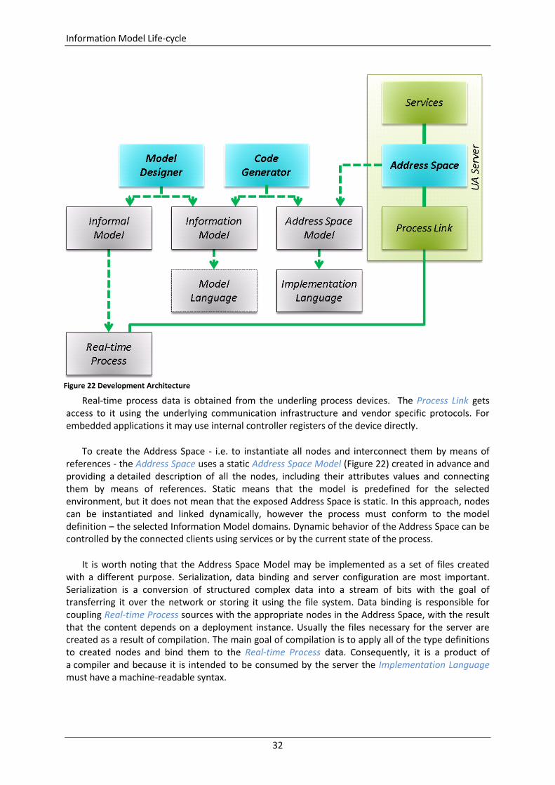
Information Model Life-cycle
32
Real-time process data is obtained from the underling process devices. The Process Link gets access to it using the underlying communication infrastructure and vendor specific protocols. For embedded applications it may use internal controller registers of the device directly.
To create the Address Space - i.e. to instantiate all nodes and interconnect them by means of references - the Address Space uses a static Address Space Model (Figure 22) created in advance and providing a detailed description of all the nodes, including their attributes values and connecting them by means of references. Static means that the model is predefined for the selected environment, but it does not mean that the exposed Address Space is static. In this approach, nodes can be instantiated and linked dynamically, however the process must conform to the model definition – the selected Information Model domains. Dynamic behavior of the Address Space can be controlled by the connected clients using services or by the current state of the process.
It is worth noting that the Address Space Model may be implemented as a set of files created with a different purpose. Serialization, data binding and server configuration are most important. Serialization is a conversion of structured complex data into a stream of bits with the goal of transferring it over the network or storing it using the file system. Data binding is responsible for coupling Real-time Process sources with the appropriate nodes in the Address Space, with the result that the content depends on a deployment instance. Usually the files necessary for the server are created as a result of compilation. The main goal of compilation is to apply all of the type definitions to created nodes and bind them to the Real-time Process data. Consequently, it is a product of a compiler and because it is intended to be consumed by the server the Implementation Language must have a machine-readable syntax.
Figure 22 Development Architecture
Information Model Life-cycle
33
We learn from the above discussion that before nodes making up the Address Space can be instantiated by the server, we need an Address Space Model, which must be compliant with the selected Information Model domains. Additionally, from the section Information Models Creation we know that the Information Model domains may be designed from scratch or adopted on the grounds of companion specifications. In any case we cannot avoid the Information Model design phase. This phase is illustrated in Figure 22 where Informal Model represents all knowledge, experience and documents that can be collected and used to design an appropriate model according to the specification. This process is similar to writing the code of a program, and predefined Information Model domains can be recognized as libraries to promote resources reusability. Predefined models not only improve the performance of the design process, but what is more importantly they make a foundation for interoperability.
As it was described in the section Information Model, any model is designed with the goal of formally determining the information that is to be used to describe the Real-time Process state and its behavior. It is accomplished by the definition of types. This way we can create autonomous, deployment independent, reusable definitions. The main challenge is to obtain an appropriate level of model simplicity. At the same time it is worth noting that simplicity is not born by simplification but is rather a result of abstraction, i.e. while designing a model the Real-time Process details should not be neglected but hidden if necessary. The deployment independency and reusability means that the model must not depend on the production environment.
To make the process not dependent on the design and deployment environment any simple text editor should meet requirements of the Model Designer. On the other hand, with the goal of minimizing the effort and change the work character form development to engineering, the model design process could also be supported by any smart tool. Anyway, result of this work must be preserved for further processing, so the Information Model representation must be encoded as a document in a format which is both human-readable and machine-readable. Additionally, it must support an appropriate level of redundancy. Redundancy is required to allow members to exchange partial work and improve robustness against typical errors and mistakes. For this purpose an appropriate Model Language is required. The Model Language is defined by syntax and semantics rules that should be commonly known to make the document interchangeable between varieties of users.
The next step in the Information Model life-cycle is the creation of its representation in a format appropriate for the implementation of the Address Space function class. This class is responsible for Address Space instantiation at runtime. The Address Space Model representation is usually generated by a compiler that couples selected Information Model domains and creates a set of documents containing all required information necessary to instantiate and interconnect nodes at runtime. The generator could be an independent product or it can be embedded into the UA Server or Model Designer. The main advantage of embedding the generator is the reduction of the number of design phases from three to two.
The architecture presented in this section and the model life-cycle is simplified. In a real scenario additional processing of the results of Model Compiler is usually necessary to deploy the model in production environment.
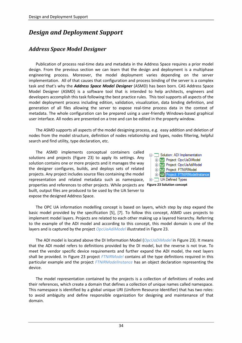
Design and Deployment Support
34
Design and Deployment Support
Address Space Model Designer
Publication of process real-time data and metadata in the Address Space requires a prior model design. From the previous section we can learn that the design and deployment is a multiphase engineering process. Moreover, the model deployment varies depending on the server implementation. All of that causes that configuration and process binding of the server is a complex task and that’s why the Address Space Model Designer (ASMD) has been born. CAS Address Space Model Designer (ASMD) is a software tool that is intended to help architects, engineers and developers accomplish this task following the best practice rules. This tool supports all aspects of the model deployment process including edition, validation, visualization, data binding definition, and generation of all files allowing the server to expose real-time process data in the context of metadata. The whole configuration can be prepared using a user-friendly Windows-based graphical user interface. All nodes are presented on a tree and can be edited in the property window.
The ASMD supports all aspects of the model designing process, e.g. easy addition and deletion of nodes from the model structure, definition of nodes relationship and types, nodes filtering, helpful search and find utility, type declaration, etc.
The ASMD implements conceptual containers called solutions and projects (Figure 23) to apply its settings. Any solution contains one or more projects and it manages the way the designer configures, builds, and deploys sets of related projects. Any project includes source files containing the model representation and related metadata such as namespace, properties and references to other projects. While projects are built, output files are produced to be used by the UA Server to expose the designed Address Space.
The OPC UA information modelling concept is based on layers, which step by step expand the basic model provided by the specification [5], [7]. To follow this concept, ASMD uses projects to implement model layers. Projects are related to each other making up a layered hierarchy. Referring to the example of the ADI model and according to this concept, this model domain is one of the layers and is captured by the project OpcUaAdiModel illustrated in Figure 23.
The ADI model is located above the DI Information Model (OpcUaDiModel in Figure 23). It means that the ADI model refers to definitions provided by the DI model, but the reverse is not true. To meet the vendor specific device requirements and further expand the ADI model, the next layers shall be provided. In Figure 23 project FTNIRModel contains all the type definitions required in this particular example and the project FTNIRModelInstance has an object declaration representing the device.
The model representation contained by the projects is a collection of definitions of nodes and their references, which create a domain that defines a collection of unique names called namespace. This namespace is identified by a global unique URI (Uniform Resource Identifier) that has two roles: to avoid ambiguity and define responsible organization for designing and maintenance of that domain.
Figure 23 Solution concept
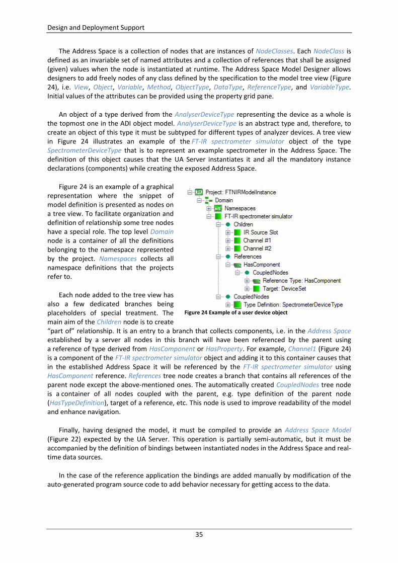
Design and Deployment Support
35
The Address Space is a collection of nodes that are instances of NodeClasses. Each NodeClass is defined as an invariable set of named attributes and a collection of references that shall be assigned (given) values when the node is instantiated at runtime. The Address Space Model Designer allows designers to add freely nodes of any class defined by the specification to the model tree view (Figure 24), i.e. View, Object, Variable, Method, ObjectType, DataType, ReferenceType, and VariableType. Initial values of the attributes can be provided using the property grid pane.
An object of a type derived from the AnalyserDeviceType representing the device as a whole is the topmost one in the ADI object model. AnalyserDeviceType is an abstract type and, therefore, to create an object of this type it must be subtyped for different types of analyzer devices. A tree view in Figure 24 illustrates an example of the FT-IR spectrometer simulator object of the type SpectrometerDeviceType that is to represent an example spectrometer in the Address Space. The definition of this object causes that the UA Server instantiates it and all the mandatory instance declarations (components) while creating the exposed Address Space.
Figure 24 is an example of a graphical representation where the snippet of model definition is presented as nodes on a tree view. To facilitate organization and definition of relationship some tree nodes have a special role. The top level Domain node is a container of all the definitions belonging to the namespace represented by the project. Namespaces collects all namespace definitions that the projects refer to.
Each node added to the tree view has also a few dedicated branches being placeholders of special treatment. The main aim of the Children node is to create “part of” relationship. It is an entry to a branch that collects components, i.e. in the Address Space established by a server all nodes in this branch will have been referenced by the parent using a reference of type derived from HasComponent or HasProperty. For example, Channel1 (Figure 24) is a component of the FT-IR spectrometer simulator object and adding it to this container causes that in the established Address Space it will be referenced by the FT-IR spectrometer simulator using HasComponent reference. References tree node creates a branch that contains all references of the parent node except the above-mentioned ones. The automatically created CoupledNodes tree node is a container of all nodes coupled with the parent, e.g. type definition of the parent node (HasTypeDefinition), target of a reference, etc. This node is used to improve readability of the model and enhance navigation.
Finally, having designed the model, it must be compiled to provide an Address Space Model (Figure 22) expected by the UA Server. This operation is partially semi-automatic, but it must be accompanied by the definition of bindings between instantiated nodes in the Address Space and real-time data sources.
In the case of the reference application the bindings are added manually by modification of the auto-generated program source code to add behavior necessary for getting access to the data.
Figure 24 Example of a user device object
Design and Deployment Support
36
For generic solutions, the Address Space Model Designer can be provided with an external component supporting the selected server configuration in the context of the model. The configuration in the context of the model means that the tool offers the possibility of selecting real-time data source for each instantiated node independently, e.g. selecting a register of the controller or a tag from an OPC DA client subscription.
Visualization
The OPC UA Address Space Model Designer offers diverse views, flexible filtering and simulation functionalities to create a customized image of the model most appropriate for the current task to view items and perform item management tasks. These features not only increase the designing efficiency but also improve robustness of the process by avoiding unexpected structural errors at the very early development stage.
The model can be visualized using the following modes: Information Model (model) view (2D/3D), Address Space (browse) view (2D). In 2D - OPC UA graphical notation is used, in 3D views - the designer can use scaling, rotating and change the view point to tailor the display to individual needs. A selected node, its properties and references can be edited using the property pane or custom editors.
Build support
Building, debugging, and testing are key activities for developing and finishing robust UA applications. The tools provided with the ASMD enable you to identify and resolve errors efficiently, and test your model in a variety of ways without the necessity of postponing it up to the UA server development. It, therefore, makes the model designing process completely independent of software development and to be successfully accomplished by real-time process information architects. This tool can be used independently of any UA application development environment, but - to utilize the model - it must be used for instantiating the content of the Address Space by a UA server. The main aim of the ASMD is to achieve this goal without any programming skills.
Interoperability without programming
Architecture of the OPC UA Address Space Model Designer allows vendors of the UA servers to develop plug-ins providing a configuration editor. The editor is used to modify the general settings and define model nodes data-bindings with the real-time process. Advantages of this solution are as follows:
Simple configuration
No programming skills are required
An easier way to move your old OPC server to the Unified Architecture world
OPC UA E-book
The Address Space Model Designer is also an intelligent eBook. It contains much useful information about UA specifications, address space concept, information model and development of the OPC UA models. What is more, a smart content positioning system of the help window can follow object selections in the GUI. The content of the book is available online so it is continuously improved
Bibliography
37
to follow the specification development progress. This software takes the advantage of automatic update functionality. Both those features guarantee that your development environment is always up to date.
Thanks to the intelligent book idea, this tool is very useful not only for OPC UA professionals, but also for the beginners who want to learn about the OPC UA address space concept.
OPC Foundation’s OPC UA SDK support
OPC Foundation has already released the UA Software Development Kit that is a collection of libraries, applications and source code that allow developers to build UA applications. Any developer who wants to create an OPC UA server of his own has to accomplish many tasks, but one of the most important is preparing of a model. This could be a hard task; OPC Foundation UA SDK does not include any tool, which helps prepare such a model. The model must be made from scratch by editing the xml file. Thanks to the OPC UA Address Space Model Designer, fully compliant with this SDK, preparation of the xml file that defines the model is much easier.
Award winning
The editorial board of Control Engineering Poland magazine granted the “2009 Product of thehttp://www.commsvr.com/Portals/1/P_News/CE_00.jpg Year” awards. The OPC UA Address Space Model Designer was the winner in the “User interfaces” category; experienced industrial automation experts praised it for innovation, user-friendliness, ease of use and possibilities of practical application.
Features
Allows creating, displaying and editing OPC UA models that are compatible with the OPC Unified Architecture address space concept.
Provides the comprehensive intelligent book, the content of which is available online so it is continuously improved and always up to date.
The content smart positioning system allows for providing context sensitive help.
No XML file editing is required.
No programming skills are required.
Created for developers and engineers, for professionals and beginners.
Bibliography
[1] http://www.commsvr.com/UAModelDesigner/ OPC Unified Architecture e-book, 2010. [2] Jürgen Lange, Frank Iwanitz, Thomas J. Burke. Von Data Access bis Unified Architecture. Hüthig
Fachverlag, 2009. [3] Wolfgang Mahnke, Stefan Helmut Leitner, Matthias Damm. OPC Unified Architecture. Berlin:
Springer, 2009. [4] OPC UA Specification: Part 1 – Concepts, Version 1.0 or later. OPC Foundation, 2009. [5] OPC UA Specification: Part 3 – Address Space Model, Version 1.0 or later. OPC Foundation,
2009. [6] OPC UA Specification: Part 4 – Services, Version 1.0 or later. OPC Foundation, 2009.

Bibliography
38
[7] OPC UA Specification: Part 5 – Information Model, Version 1.0 or later. OPC Foundation, 2009. [8] OPC Unified Architecture Companion Specification for Analyser Devices. OPC Foundation, 2009. [9] OPC Unified Architecture Companion Specification for Devices. OPC Foundation, 2009. [10] OPC UA Object Oriented Internet, Opc-ua-ooi open source project on GitHub,
http://mpostol.github.io/OPC-UA-OOI/, 2015