ontinui C ous Gas Analysis - Siemens · PDF fileContinuious Gas Analysis Continu. ......
90
Description · 07/2012 PROFIBUS DP/PA interface Gas analyzers of Series 6 and ULTRAMAT 23 Continui ous Gas Analysis
-
Upload
nguyenduong -
Category
Documents
-
view
217 -
download
0
Transcript of ontinui C ous Gas Analysis - Siemens · PDF fileContinuious Gas Analysis Continu. ......

Description · 07/2012
P PROFIBUS DP/PA interface
G Gas analyzers of Series 6 and ULTRAMAT 23
Continuious Gas AnalysisContinu


Continuous gas analysis
Analyzers of Series 6 and ULTRAMAT 23 PROFIBUS DP/PA interface
Operating Manual
06/2012 A5E00054148-06
Introduction 1
Safety notes 2
Assembly guidelines 3
Commissioning 4
Operation 5
User data via PROFIBUS 6
Alarm, error, and system messages
7
Maintenance and troubleshooting
8
Technical specifications 9
Appendix A
List of abbreviations B

Siemens AG Industry Sector Postfach 48 48 90026 NÜRNBERG GERMANY
Order number: A5E00054148 Ⓟ 01/2013 Technical data subject to change
Copyright © Siemens AG 2012. All rights reserved
Legal information Warning notice system
This manual contains notices you have to observe in order to ensure your personal safety, as well as to prevent damage to property. The notices referring to your personal safety are highlighted in the manual by a safety alert symbol, notices referring only to property damage have no safety alert symbol. These notices shown below are graded according to the degree of danger.
DANGER indicates that death or severe personal injury will result if proper precautions are not taken.
WARNING indicates that death or severe personal injury may result if proper precautions are not taken.
CAUTION indicates that minor personal injury can result if proper precautions are not taken.
NOTICE indicates that property damage can result if proper precautions are not taken.
If more than one degree of danger is present, the warning notice representing the highest degree of danger will be used. A notice warning of injury to persons with a safety alert symbol may also include a warning relating to property damage.
Qualified Personnel The product/system described in this documentation may be operated only by personnel qualified for the specific task in accordance with the relevant documentation, in particular its warning notices and safety instructions. Qualified personnel are those who, based on their training and experience, are capable of identifying risks and avoiding potential hazards when working with these products/systems.
Proper use of Siemens products Note the following:
WARNING Siemens products may only be used for the applications described in the catalog and in the relevant technical documentation. If products and components from other manufacturers are used, these must be recommended or approved by Siemens. Proper transport, storage, installation, assembly, commissioning, operation and maintenance are required to ensure that the products operate safely and without any problems. The permissible ambient conditions must be complied with. The information in the relevant documentation must be observed.
Trademarks All names identified by ® are registered trademarks of Siemens AG. The remaining trademarks in this publication may be trademarks whose use by third parties for their own purposes could violate the rights of the owner.
Disclaimer of Liability We have reviewed the contents of this publication to ensure consistency with the hardware and software described. Since variance cannot be precluded entirely, we cannot guarantee full consistency. However, the information in this publication is reviewed regularly and any necessary corrections are included in subsequent editions.

PROFIBUS DP/PA interface Operating Manual, 06/2012, A5E00054148-06 3
Table of contents
1 Introduction................................................................................................................................................ 7
1.1 Notes for operators ........................................................................................................................7
1.2 Benefits ..........................................................................................................................................7
1.3 Additional information ....................................................................................................................9
1.4 Delivery information .....................................................................................................................10
1.5 PROFIBUS modules ....................................................................................................................10
2 Safety notes............................................................................................................................................. 11
2.1 Precondition for use .....................................................................................................................11
2.2 Improper device modifications .....................................................................................................11
3 Assembly guidelines ................................................................................................................................ 13
3.1 Safety instructions........................................................................................................................13 3.1.1 Unprotected cable ends ...............................................................................................................13 3.1.2 Insufficient isolation of non-intrinsically safe and intrinsically safe circuits..................................13
3.2 Bus connection for rack-mounted analyzers of Series 6 .............................................................14
3.3 Bus connection for ULTRAMAT 23..............................................................................................15
3.4 Bus connection for field devices of Series 6 ................................................................................16
3.5 PROFIBUS plug connectors ........................................................................................................17
3.6 Binary inputs and relay outputs of the add-on board...................................................................19 3.6.1 Connector assignment of the rack-mounted analyzers of Series 6 and the ULTRAMAT 23 ......19 3.6.2 Connector assignment for field devices of Series 6.....................................................................20 3.6.3 Design of add-on board ...............................................................................................................21 3.6.4 Fitting or retrofitting the add-on board .........................................................................................21 3.6.4.1 Rack-mounted analyzers of Series 6...........................................................................................22 3.6.4.2 ULTRAMAT 23.............................................................................................................................24 3.6.4.3 Field devices of Series 6..............................................................................................................26
4 Commissioning ........................................................................................................................................ 29
4.1 General information .....................................................................................................................29
4.2 Use of a configuration tool ...........................................................................................................30 4.2.1 Selection of the target configuration ............................................................................................30 4.2.1.1 Device-specific selection with device revision 1 ..........................................................................30 4.2.1.2 Block-specific selection with device revision 2 ............................................................................31 4.2.1.3 Setting the PROFIBUS address...................................................................................................35 4.2.1.4 SIMATIC PDM device catalog .....................................................................................................36 4.2.1.5 Starting SIMATIC PDM................................................................................................................37

Table of contents
PROFIBUS DP/PA interface 4 Operating Manual, 06/2012, A5E00054148-06
5 Operation................................................................................................................................................. 39
5.1 Parameter assignment on the device ......................................................................................... 39 5.1.1 Analyzers of Series 6 .................................................................................................................. 39 5.1.2 ULTRAMAT 23............................................................................................................................ 41
5.2 Settings with SIMATIC PDM ....................................................................................................... 43 5.2.1 TAG/Analog Input Block.............................................................................................................. 43 5.2.2 Adjusting to a desired process value .......................................................................................... 43 5.2.3 Electrical attenuation................................................................................................................... 44 5.2.4 Warning and alarm limits............................................................................................................. 44 5.2.5 Response in event of failure ....................................................................................................... 45 5.2.6 AUTOCAL ................................................................................................................................... 45 5.2.7 Simulations.................................................................................................................................. 46 5.2.7.1 Simulation of an output ............................................................................................................... 46 5.2.7.2 Simulation of an input.................................................................................................................. 46 5.2.8 Reset functions ........................................................................................................................... 47 5.2.8.1 Resetting to the as-supplied state............................................................................................... 47 5.2.8.2 Resetting the PROFIBUS address.............................................................................................. 48
5.3 Operation with SIMATIC PDM .................................................................................................... 48
6 User data via PROFIBUS ........................................................................................................................ 49
6.1 Device revisions .......................................................................................................................... 49
6.2 Data profile.................................................................................................................................. 51
6.3 Cyclic data transfer ..................................................................................................................... 53 6.3.1 Slots for cyclic data transfer ........................................................................................................ 53 6.3.2 Measured value/status ................................................................................................................ 54 6.3.3 Triggering AUTOCAL.................................................................................................................. 54 6.3.4 Assigning relay outputs ............................................................................................................... 55 6.3.5 Reading digital inputs.................................................................................................................. 56
6.4 Non-cyclic data transfer .............................................................................................................. 57 6.4.1 Measured value commands........................................................................................................ 57 6.4.2 Calibration commands ................................................................................................................ 58 6.4.3 Commands for device hardware ................................................................................................. 59 6.4.4 General commands..................................................................................................................... 61
6.5 Parameter description ................................................................................................................. 62 6.5.1 Parameter tables......................................................................................................................... 62 6.5.2 Structure of the error messages ................................................................................................. 63 6.5.3 Data type DS-33.......................................................................................................................... 64 6.5.4 Data type DS-34.......................................................................................................................... 66 6.5.5 Generic station description.......................................................................................................... 66

Table of contents
PROFIBUS DP/PA interface Operating Manual, 06/2012, A5E00054148-06 5
7 Alarm, error, and system messages ........................................................................................................ 67
7.1 Status and error messages with SIMATIC PDM..........................................................................67
7.2 Diagnostics information................................................................................................................68 7.2.1 ULTRAMAT 6...............................................................................................................................68 7.2.2 CALOMAT 6.................................................................................................................................69 7.2.3 OXYMAT 6 and OXYMAT 61.......................................................................................................70 7.2.4 ULTRAMAT 23.............................................................................................................................71 7.2.5 FIDAMAT 6 ..................................................................................................................................72 7.2.6 CALOMAT 62...............................................................................................................................73 7.2.7 OXYMAT 64.................................................................................................................................74 7.2.8 Display of quality status in SIMATIC PDM...................................................................................75
8 Maintenance and troubleshooting............................................................................................................ 77
8.1 Possible operating problems........................................................................................................77
8.2 Spare parts...................................................................................................................................78 8.2.1 Firmware/retrofitting kits/spare parts packages of PROFIBUS modules.....................................78 8.2.2 Firmware of basic devices ...........................................................................................................79
9 Technical specifications........................................................................................................................... 81
A Appendix.................................................................................................................................................. 83
A.1 Return delivery.............................................................................................................................83
B List of abbreviations................................................................................................................................. 85
B.1 List of abbreviations .....................................................................................................................85
Glossary .................................................................................................................................................. 87
Index........................................................................................................................................................ 89

Table of contents
PROFIBUS DP/PA interface 6 Operating Manual, 06/2012, A5E00054148-06

PROFIBUS DP/PA interface Operating Manual, 06/2012, A5E00054148-06 7
Introduction 11.1 Notes for operators
This description applies to the following gas analyzers:
ULTRAMAT 6 7MB2111, 7MB2112, 7MB2117,
7MB2121, 7MB2123, 7MB2124, 7MB2127, 7MB2128 OXYMAT 6 7MB2011, 7MB2017, 7MB2021, 7MB2027 ULTRAMAT/OXYMAT 6 7MB2023, 7MB2028, 7MB2024, 7MB2026 CALOMAT 6 7MB2511, 7MB2517, 7MB2521, 7MB2527 CALOMAT 62 7MB2541, 7MB2547, 7MB2531, 7MB2537 ULTRAMAT 23 7MB2331, 7MB2333, 7MB2334, 7MB2335, 7MB2337,
7MB2338 OXYMAT 61 7MB2001 OXYMAT 64 7MB2041, 7MB2047 FIDAMAT 6 7MB2421, 7MB2427
This description contains all information required for operation of these gas analyzers via the PROFIBUS PA and PROFIBUS DP communication systems. It provides important notes, additions, and corrections to the manuals and operating instructions for the relevant devices. These documents must also always be observed.
1.2 Benefits The usual transmission of measured values and fault messages via analog and digital outputs requires complex cabling. In contrast, when using PROFIBUS DP and PROFIBUS PA, one single two-wire conductor is sufficient for digital transmission of all measured values (also from several channels), status information or diagnostics functions for preventive maintenance, for example.
The PROFIBUS DP version is widely used in factory automation because of its high transmission rate for relatively small data quantities per device. It is used as the basis for the add-on board of the S 6 analyzers. The PROFIBUS PA version works in line with the following equation:

Introduction 1.2 Benefits
PROFIBUS DP/PA interface 8 Operating Manual, 06/2012, A5E00054148-06
The limited dynamic performance of 4 to 20 mA signals can be replaced, the laborious configuration of measuring ranges can be omitted. By using simulated measured values without media, increased reliability can be provided for the plant configuration and configuration errors can be avoided. Parameter sets can be generated offline (from your desk) and subsequently downloaded and saved in the device. Local operation can thus be reduced to a minimum.
The Siemens gas analyzers
● OXYMAT 6, OXYMAT 61, OXYMAT 64
● ULTRAMAT 6, ULTRAMAT 23
● ULTRAMAT/OXYMAT 6
● CALOMAT 6, CALOMAT 62
● FIDAMAT 6
are PROFIBUS-compatible when using an optional plug-in card (retrofitting also possible) and therefore comply with the "Device profile for analyzers" defined as binding by PI (PROFIBUS International).
Customer benefits include an enormous savings potential in all plant areas, covering configuration and commissioning, operation and maintenance, up to subsequent plant expansions.
Operation of the gas analyzers from a control system or a separate PC is possible using the SIMATIC PDM (Process Device Manager) operator tool; this is software which runs under Windows and which can also be integrated into the SIMATIC PCS7 process control system. This permits a clear presentation of the integration of the analyzers in the system as well as the complex parameter structure of the analyzers.
Direct connection of the analyzers to a control system is also possible without PDM, e.g. using STEP7, but this requires additional programming and does not offer the same user-friendliness. In most cases, this direct connection can therefore only be used if acyclic (device operation) data is not used.
Both graphic displays and values can be output on a PC. Signaling of maintenance, fault and diagnostics information is cyclic. This data is displayed in plain text when using SIMATIC PDM. The digital outputs can also be switched using cyclic services, thus permitting triggering of relays over PROFIBUS (e.g. for measuring point switchover, calibration etc.).
Introduction 1.3 Additional information
PROFIBUS DP/PA interface Operating Manual, 06/2012, A5E00054148-06 9
1.3 Additional information When designing PROFIBUS networks, we recommend the corresponding components from the SIEMENS Catalog ST PI. The order numbers of this catalog are as follows:
● E86060-K4660-A101-A3 (German)
● E86060-K4660-A101-A3-7600 (English)
All information on designing PROFIBUS networks can be found in the "PROFIBUS networks" manual: The order numbers for this are as follows:
● 6GK1970-5CA20-0AA0 (German)
● 6GK1970-5CA20-0AA1 (English).
● 6GK1970-5CA20-0AA2 (French)
● 6GK1970-5CA20-0AA3 (Spanish)
● 6GK1970-5CA20-0AA4 (Italian)
The following documentation can also provide important information on the same topic:
DP/PA bus coupler Issue 2 Order number 6ES7 1757-0AA00-8AA0 Manual for PROFIBUS networks Order number 6GK1 970-5CA00-0AA0 (German) or Order number 6GK1 970-5CA00-0AA1 (English) Documentation package Order number 6ES7 398-8RA00-8AA0
Information on designing PROFIBUS networks is also available under: Siemens PROFIBUS web link (http://www.automation.siemens.com/mcms/automation/en/industrial-communications/profibus/Pages/Default.aspx)
You can also obtain further information from Profibus International (PI) or on the Internet under PROFIBUS (PI) (http://www.profibus.com).
Address: PROFIBUS-Nutzer-Organisation Haid-und-Neu-Str. 7 D-76131 Karlsruhe, Germany
Tel.: ++49 721 / 96 58 590 Fax: ++49 721 / 96 58 589

Introduction 1.4 Delivery information
PROFIBUS DP/PA interface 10 Operating Manual, 06/2012, A5E00054148-06
1.4 Delivery information The respective scope of delivery is listed on the shipping documents – enclosed with the delivery – in accordance with the valid sales contract.
When opening the packaging, please observe the corresponding information on the packaging material. Check the delivery for completeness and undamaged condition. In particular, you should compare the Order No. on the rating plates with the ordering data, if available. If possible, please retain the packaging material, since you can use it again in case of return deliveries.
1.5 PROFIBUS modules PROFIBUS (PROcess FIeld BUS) is an open and standardized communication system for automation technology. Using these PROFIBUS option modules, it is possible to connect the SIEMENS gas analyzers of Series 6 and the ULTRAMAT 23 gas analyzer to PROFIBUS PA or PROFIBUS DP as follows:
● The option module A5E00034504 allows non-intrinsically safe coupling to PROFIBUS PA.
● The option module A5E00015899 Ex i allows intrinsically safe coupling to PROFIBUS PA.
● The option module A5E00019145 allows coupling to PROFIBUS DP.
NOTICE
Improper use
The option module A5E00015899 Ex i is designed for equipment to be used in hazardous areas and may only be fitted in Series 6 devices with the Ex type of protection II 3 G Ex nA II T4.

PROFIBUS DP/PA interface Operating Manual, 06/2012, A5E00054148-06 11
Safety notes 22.1 Precondition for use
This device left the factory in good working condition. In order to maintain this status and to ensure safe operation of the device, observe these instructions and all the specifications relevant to safety.
Observe the information and symbols on the device. Do not remove any information or symbols from the device. Always keep the information and symbols in a completely legible state.
2.2 Improper device modifications
WARNING Improper device modifications
Danger to personnel, system and environment can result from modifications to the device, particularly in hazardous areas. Only carry out modifications that are described in the instructions for the device. Failure
to observe this requirement cancels the manufacturer's warranty and the product approvals.

Safety notes 2.2 Improper device modifications
PROFIBUS DP/PA interface 12 Operating Manual, 06/2012, A5E00054148-06

PROFIBUS DP/PA interface Operating Manual, 06/2012, A5E00054148-06 13
Assembly guidelines 33.1 Safety instructions
3.1.1 Unprotected cable ends
WARNING Unprotected cable ends
Danger of explosion through unprotected cable ends in hazardous areas. Protect unused cable ends in accordance with IEC/EN 60079-14.
3.1.2 Insufficient isolation of non-intrinsically safe and intrinsically safe circuits
WARNING Insufficient isolation of non-intrinsically safe and intrinsically safe circuits
Danger of explosion in hazardous areas. When connecting intrinsically safe and non-intrinsically safe circuits ensure that isolation
is carried out properly in accordance with IEC/EN 60079-14. Make sure that you observe the device approvals applicable in your country.

Assembly guidelines 3.2 Bus connection for rack-mounted analyzers of Series 6
PROFIBUS DP/PA interface 14 Operating Manual, 06/2012, A5E00054148-06
3.2 Bus connection for rack-mounted analyzers of Series 6
Figure 3-1 Connection diagram for rack-mounted analyzers of Series 6
Assembly guidelines 3.3 Bus connection for ULTRAMAT 23
PROFIBUS DP/PA interface Operating Manual, 06/2012, A5E00054148-06 15
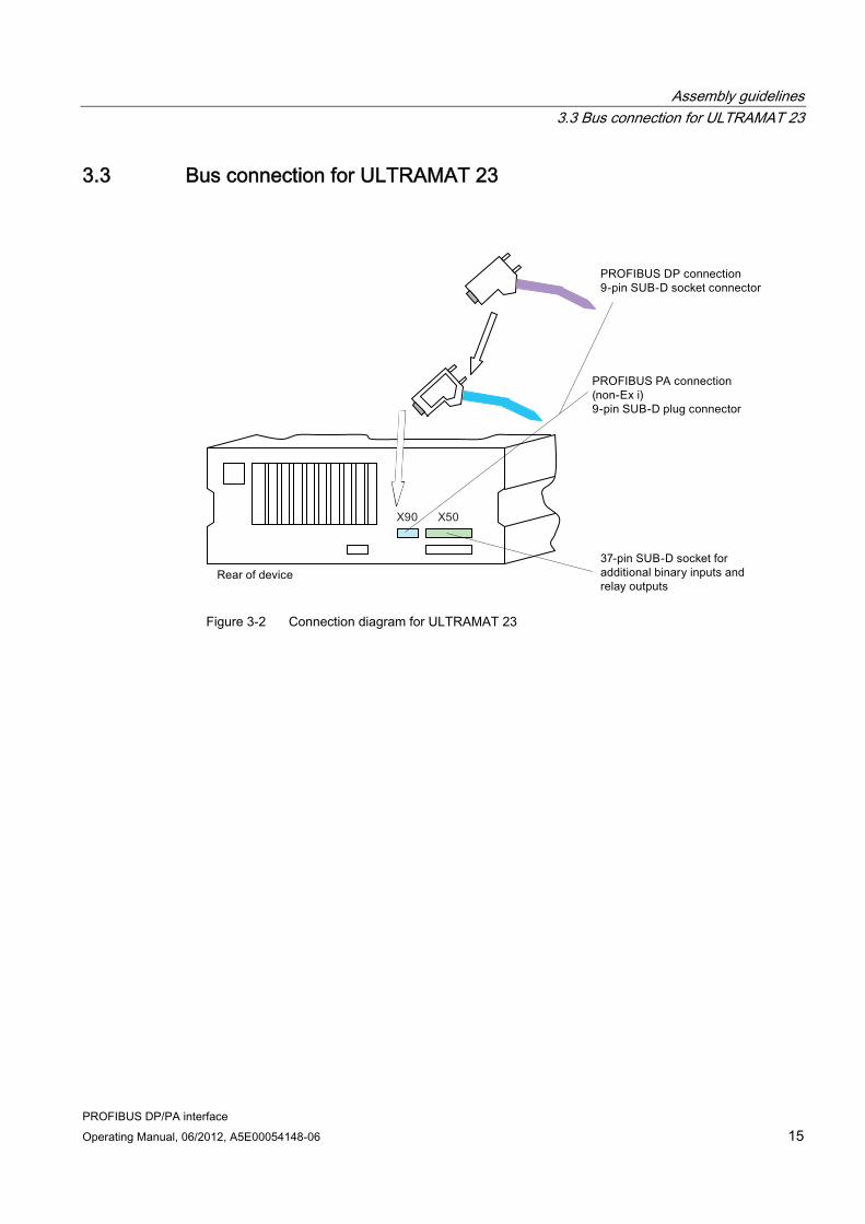
3.3 Bus connection for ULTRAMAT 23
Figure 3-2 Connection diagram for ULTRAMAT 23

Assembly guidelines 3.4 Bus connection for field devices of Series 6
PROFIBUS DP/PA interface 16 Operating Manual, 06/2012, A5E00054148-06
3.4 Bus connection for field devices of Series 6
Figure 3-3 Connection of PROFIBUS modules to field devices
NOTICE Incorrect connection
Only the module A5E00015899 Ex i may be used in field devices with Profibus connection which are used in hazardous areas. In such cases, the inputs and outputs of the 37-pin SUB-D socket may only be connected and used with special protection.
Details on this can be found in the instruction manual of the associated device and the compact operating instructions for field devices of Series 6 for use in hazardous areas.
It is essential that you observe the relevant regulations for installation and operation of systems in these areas.

Assembly guidelines 3.5 PROFIBUS plug connectors
PROFIBUS DP/PA interface Operating Manual, 06/2012, A5E00054148-06 17
3.5 PROFIBUS plug connectors
PROFIBUS plug connectors
Figure 3-4 Plug connectors
PROFIBUS PA connection Connect the PROFIBUS module using the 9-pin SUB-D socket plug connector which is included as an option with the device. With this plug connector, the bus cable can be connected via a solder joint. Alternatively, you can use a commercially available plug connector with removable terminal connection, e.g. of type SUBCON 9/F-SH from Phoenix-Contact (item no.: 2761499). PROFIBUS PA connector assignment
Function Contact PA-P (+) 3 PA-P (-) 8 None (NC) 1, 2, 4, 5, 6, 7, 9
PROFIBUS PA cable We recommend use of the following cable types (FastConnect technique):
SIEMENS order number Color Function 6XV1 830-5EH10 Blue Applications in the hazardous area 6XV1 830-5FH10 Black Applications only in the non-hazardous area
Connect the cable screen flush in the connector housing.
Assembly guidelines 3.5 PROFIBUS plug connectors
PROFIBUS DP/PA interface 18 Operating Manual, 06/2012, A5E00054148-06
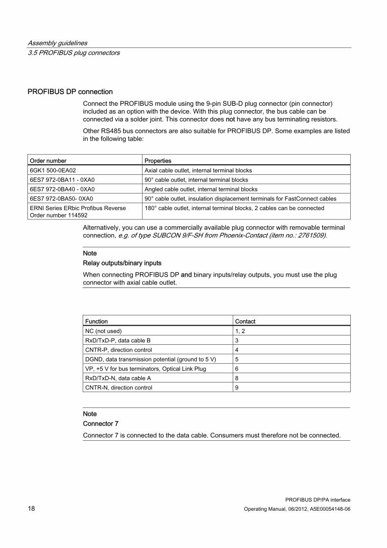
PROFIBUS DP connection Connect the PROFIBUS module using the 9-pin SUB-D plug connector (pin connector) included as an option with the device. With this plug connector, the bus cable can be connected via a solder joint. This connector does not have any bus terminating resistors.
Other RS485 bus connectors are also suitable for PROFIBUS DP. Some examples are listed in the following table:
Order number Properties 6GK1 500-0EA02 Axial cable outlet, internal terminal blocks 6ES7 972-0BA11 - 0XA0 90° cable outlet, internal terminal blocks 6ES7 972-0BA40 - 0XA0 Angled cable outlet, internal terminal blocks 6ES7 972-0BA50- 0XA0 90° cable outlet, insulation displacement terminals for FastConnect cables ERNI Series ERbic Profibus Reverse Order number 114592
180° cable outlet, internal terminal blocks, 2 cables can be connected
Alternatively, you can use a commercially available plug connector with removable terminal connection, e.g. of type SUBCON 9/F-SH from Phoenix-Contact (item no.: 2761509).
Note Relay outputs/binary inputs
When connecting PROFIBUS DP and binary inputs/relay outputs, you must use the plug connector with axial cable outlet.
Function Contact NC (not used) 1, 2 RxD/TxD-P, data cable B 3 CNTR-P, direction control 4 DGND, data transmission potential (ground to 5 V) 5 VP, +5 V for bus terminators, Optical Link Plug 6 RxD/TxD-N, data cable A 8 CNTR-N, direction control 9
Note Connector 7
Connector 7 is connected to the data cable. Consumers must therefore not be connected.

Assembly guidelines 3.6 Binary inputs and relay outputs of the add-on board
PROFIBUS DP/PA interface Operating Manual, 06/2012, A5E00054148-06 19
PROFIBUS DP cable We recommend use of the following cable type:
Order number 6XV1 830-0E10 (violet). This cable is also suitable for the FastConnect technique.
Connect the cable screen flush in the connector housing.
3.6 Binary inputs and relay outputs of the add-on board
3.6.1 Connector assignment of the rack-mounted analyzers of Series 6 and the ULTRAMAT 23
Figure 3-5 D-SUB 37 connector assignment

Assembly guidelines 3.6 Binary inputs and relay outputs of the add-on board
PROFIBUS DP/PA interface 20 Operating Manual, 06/2012, A5E00054148-06
3.6.2 Connector assignment for field devices of Series 6
M
M
21
37
1234
33343536
567891011121314151617181920212223242526272829303132
373839
Figure 3-6 Connector assignment for field devices

Assembly guidelines 3.6 Binary inputs and relay outputs of the add-on board
PROFIBUS DP/PA interface Operating Manual, 06/2012, A5E00054148-06 21
3.6.3 Design of add-on board
Figure 3-7 Design of add-on board
3.6.4 Fitting or retrofitting the add-on board
Note Firmware
When retrofitting or subsequently installing the add-on board, it may be necessary to replace the firmware.
Further details can be found in the section 'Firmware of basic devices (Page 79)' or in the device manual or operating instructions of the relevant device.

Assembly guidelines 3.6 Binary inputs and relay outputs of the add-on board
PROFIBUS DP/PA interface 22 Operating Manual, 06/2012, A5E00054148-06
3.6.4.1 Rack-mounted analyzers of Series 6
Note Wrong modules
Ehen installing the add-on board in rack-mounted analyzers of Series 6, please note that only the following boards can be used: A5E00034504 for non-intrinsically safe coupling to PROFIBUS PA A5E00019145 for coupling to PROFIBUS DP.
The ULTRAMAT 6E/OXYMAT 6E (combined analyzer) and ULTRAMAT 6E (2-channel analyzer) each require 2 PROFIBUS interface modules.
Figure 3-8 Installation diagram for add-on board in rack-mounted analyzers of Series 6

Assembly guidelines 3.6 Binary inputs and relay outputs of the add-on board
PROFIBUS DP/PA interface Operating Manual, 06/2012, A5E00054148-06 23
To install the add-on board, proceed as follows:
1. Disconnect the device from the mains.
2. Unscrew and remove the housing cover.
3. Remove the old add-on board, if there is one.
4. Fit the (new) module(s) into the rail on the base.
5. Fasten the module(s) with the M3 screws at the position intended for this purpose between the connectors on the rear panel.
6. Plug the ribbon cable connector onto the motherboard.
7. Fit the holding clamp.
8. Screw the housing cover back into place.
9. Connect the PROFIBUS cable to the device.
10. Reconnect the device to the power supply.

Assembly guidelines 3.6 Binary inputs and relay outputs of the add-on board
PROFIBUS DP/PA interface 24 Operating Manual, 06/2012, A5E00054148-06
3.6.4.2 ULTRAMAT 23
Note Wrong modules
When installing the add-on board in the ULTRAMAT 23 gas analyzer, please note that only the following boards can be used: A5E00034504 for non-intrinsically safe coupling to PROFIBUS PA A5E00019145 for coupling to PROFIBUS DP.
Figure 3-9 Installation diagram for add-on board in ULTRAMAT 23 rack-mounted analyzers

Assembly guidelines 3.6 Binary inputs and relay outputs of the add-on board
PROFIBUS DP/PA interface Operating Manual, 06/2012, A5E00054148-06 25
To install the add-on board, proceed as follows:
1. Disconnect the device from the mains.
2. Unscrew and remove the housing cover.
3. Remove the old add-on board, if there is one.
4. Fasten the module(s) with the M3 screws at the position intended for this purpose between the connectors on the rear panel.
5. A plastic bolt is included in the retrofitting kit. Use this to fasten the (new) module to the housing base.
6. Plug the ribbon cable connector onto the motherboard.
7. Screw the housing cover back into place.
8. Connect the PROFIBUS cable to the device.
9. Reconnect the device to the power supply.
Assembly guidelines 3.6 Binary inputs and relay outputs of the add-on board
PROFIBUS DP/PA interface 26 Operating Manual, 06/2012, A5E00054148-06
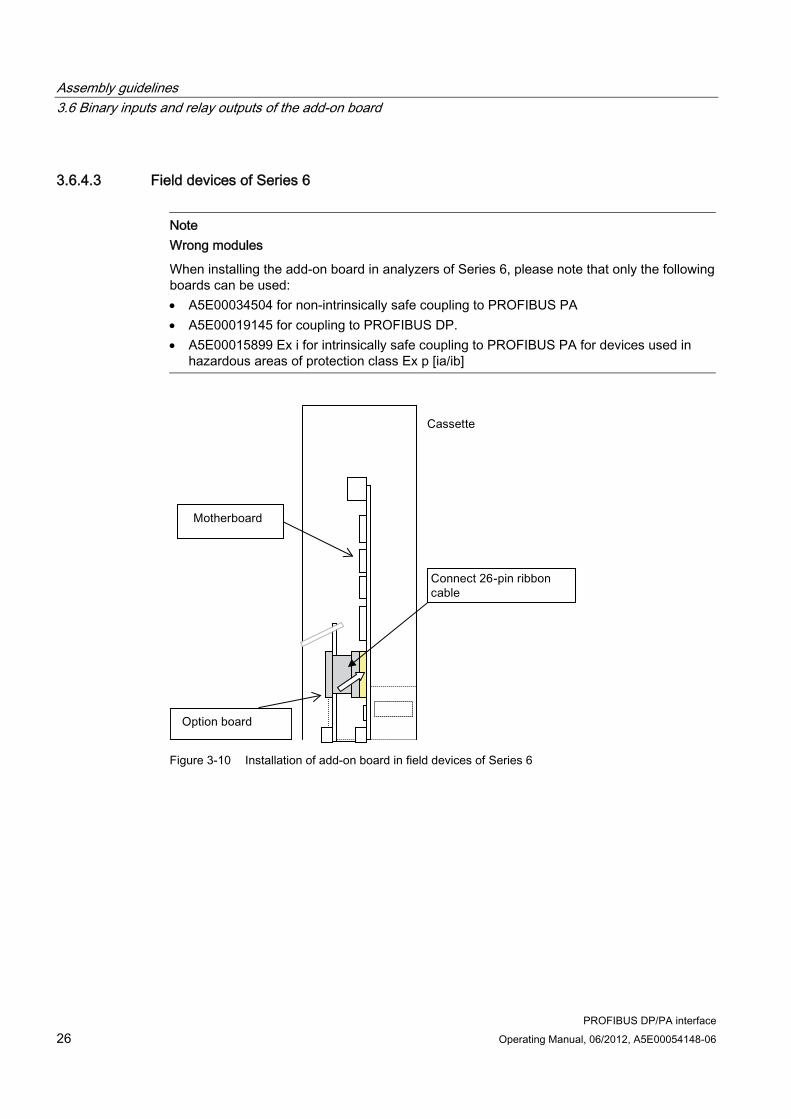
3.6.4.3 Field devices of Series 6
Note Wrong modules
When installing the add-on board in analyzers of Series 6, please note that only the following boards can be used: A5E00034504 for non-intrinsically safe coupling to PROFIBUS PA A5E00019145 for coupling to PROFIBUS DP. A5E00015899 Ex i for intrinsically safe coupling to PROFIBUS PA for devices used in
hazardous areas of protection class Ex p [ia/ib]
Figure 3-10 Installation of add-on board in field devices of Series 6

Assembly guidelines 3.6 Binary inputs and relay outputs of the add-on board
PROFIBUS DP/PA interface Operating Manual, 06/2012, A5E00054148-06 27
To install the add-on board, proceed as follows:
1. Disconnect the device from the mains.
2. Open the left door of the housing.
3. Remove the sheet-metal cover.
4. Disconnect all cables leading to the cassette.
5. Remove the sheet metal cassette from the device.
6. Remove the old add-on board, if there is one.
7. Fit the new module into the rail.
8. Fasten the module with the M3 screws at the position intended for this purpose between the connectors on the underside of the cassette
9. Hook the metal bracket onto the upper edge of the option module.
10. Plug the ribbon cable connector onto the motherboard.
11. Connect the 37-pin SUB-D socket of the option module to the terminal block in the device.
12. Fit the sheet-metal cassette back into the device.
13. Screw the sheet-metal cover back into place.
14. Connect the PROFIBUS cable to the device.
15. Reconnect the device to the power supply.

Assembly guidelines 3.6 Binary inputs and relay outputs of the add-on board
PROFIBUS DP/PA interface 28 Operating Manual, 06/2012, A5E00054148-06
PROFIBUS DP/PA interface Operating Manual, 06/2012, A5E00054148-06 29
Commissioning 44.1 General information
Following installation of all components required for communication over PROFIBUS, you must still carry out the following steps:
● Check the firmware of your device. The assignment of the firmware to the device can be found in section Device revisions (Page 49). If retrofitting is necessary, you must replace the firmware block. A list of suitable blocks can be found in section Firmware/retrofitting kits/spare parts packages of PROFIBUS modules (Page 78).
● Set the PROFIBUS station address. This is described in section Parameter assignment on the device (Page 39). If the device is not detected during cyclic data transfer, check whether the ID number in the device parameter set is '1 (device-specific)'.
● We recommend a PC software program such as SIMATIC PDM for operation via PROFIBUS. Installation and the steps required for commissioning are described in the associated operating instructions and online help; refer to the information provided there.

Commissioning 4.2 Use of a configuration tool
PROFIBUS DP/PA interface 30 Operating Manual, 06/2012, A5E00054148-06
4.2 Use of a configuration tool The following example demonstrates the selection of the gas analyzer using the configuration tool STEP 7 HW-Config.
4.2.1 Selection of the target configuration The device concerned has either a DP or PA interface. Select the appropriate device from the DP or PA catalog.
4.2.1.1 Device-specific selection with device revision 1
Figure 4-1 Device-specific selection of the target configuration with device revision 1
When selecting a device, the slots with the device-specific function blocks are output.

Commissioning 4.2 Use of a configuration tool
PROFIBUS DP/PA interface Operating Manual, 06/2012, A5E00054148-06 31
4.2.1.2 Block-specific selection with device revision 2
delete
Figure 4-2 Output of available slots
When selecting a device, the slots are output which are not currently assigned to a function and are therefore available.

Commissioning 4.2 Use of a configuration tool
PROFIBUS DP/PA interface 32 Operating Manual, 06/2012, A5E00054148-06
The function of the slot is output by selecting it and deleting the description 'Not in cyclic data transfer'.
Commissioning 4.2 Use of a configuration tool
PROFIBUS DP/PA interface Operating Manual, 06/2012, A5E00054148-06 33
Available slotis highlighted
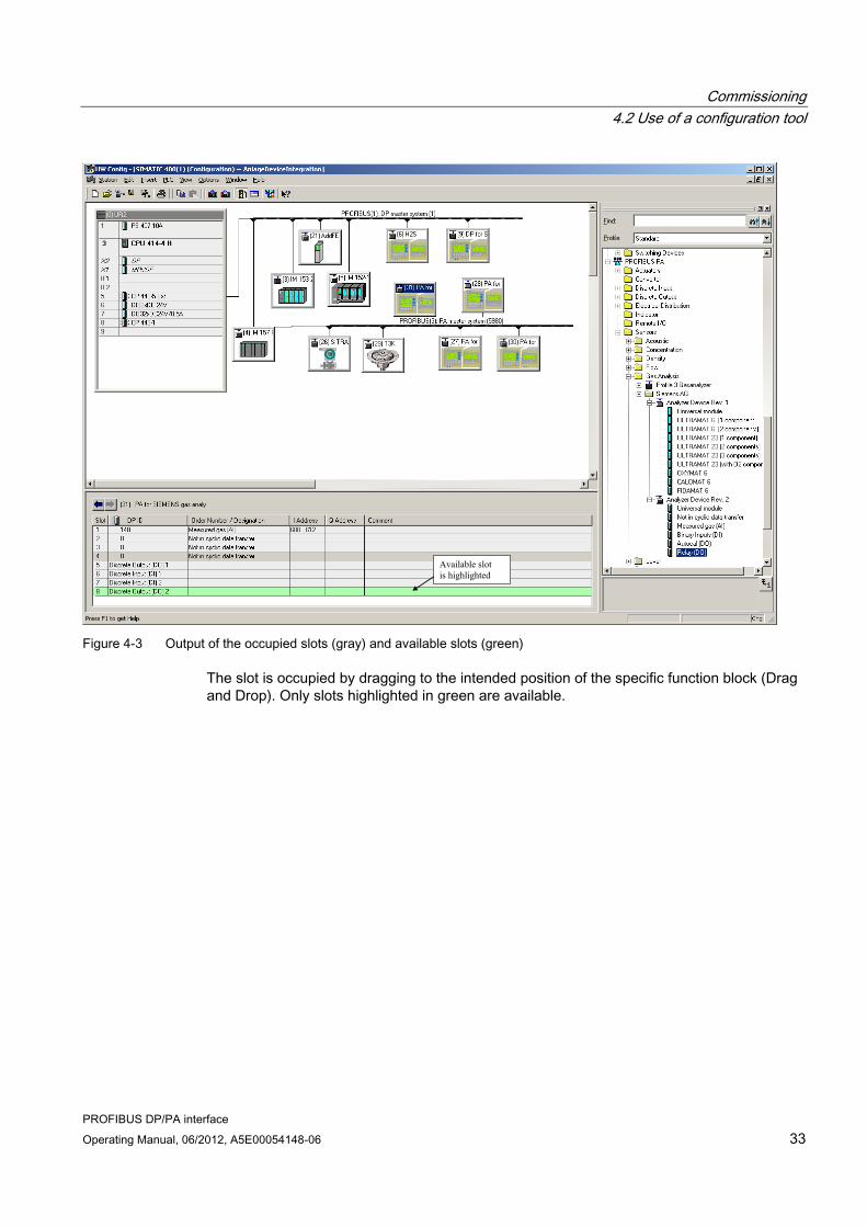
Figure 4-3 Output of the occupied slots (gray) and available slots (green)
The slot is occupied by dragging to the intended position of the specific function block (Drag and Drop). Only slots highlighted in green are available.

Commissioning 4.2 Use of a configuration tool
PROFIBUS DP/PA interface 34 Operating Manual, 06/2012, A5E00054148-06
Figure 4-4 Configuration with completely occupied slots

Commissioning 4.2 Use of a configuration tool
PROFIBUS DP/PA interface Operating Manual, 06/2012, A5E00054148-06 35
4.2.1.3 Setting the PROFIBUS address
Figure 4-5 Setting the PROFIBUS address

Commissioning 4.2 Use of a configuration tool
PROFIBUS DP/PA interface 36 Operating Manual, 06/2012, A5E00054148-06
4.2.1.4 SIMATIC PDM device catalog
You can select the appropriate device by double-clicking on the new device icon.

Commissioning 4.2 Use of a configuration tool
PROFIBUS DP/PA interface Operating Manual, 06/2012, A5E00054148-06 37
4.2.1.5 Starting SIMATIC PDM
SIMATIC PDM can be started following selection of the device.

Commissioning 4.2 Use of a configuration tool
PROFIBUS DP/PA interface 38 Operating Manual, 06/2012, A5E00054148-06

PROFIBUS DP/PA interface Operating Manual, 06/2012, A5E00054148-06 39
Operation 55.1 Parameter assignment on the device
5.1.1 Analyzers of Series 6
Note General information
The basic principles for operation on the device are described in the manual or operating instructions of the associated device in the section 'Operation'.
The station address can be set in the main menu under Configuration. Cyclic communication must be terminated prior to modifying one of these parameters, and restarted when the menu is left.
This function is coded and requires the level 2 code. The following display then appears, for example:
Relay on PB :off:
Address :126:TAG : OXYMATSIXTYONEIdent number : 1:
Software vers: 2.0.0Boot software: 0.2.0
90 PROFIBUS config. O2

Operation 5.1 Parameter assignment on the device
PROFIBUS DP/PA interface 40 Operating Manual, 06/2012, A5E00054148-06
You can then set the following parameters:
● Address: The PROFIBUS station address can be set here. The address can be set from 0 to 126.
● TAG Display of name assigned to the device in the network (or the first 16 characters).
● Ident number This parameter is used to set the configuration response of the device. The values 0, 1 and 3 can be set for the parameter. They have the following meanings:
– 0: Only the Profil Ident number is acknowledged positively
– 1: Only the device-specific Ident number is acknowledged positively Note: In order to work with the provided GSD and DD, the ‚Ident number’ parameter must have the value 1.
– 3: Only the Profil Ident number for multivariable devices (complex analyzers) is acknowledged positively.
● Relay by PB This function can be used to control the 8 relays of the add-on card via PROFIBUS. To allow activation, none of these relays must already be occupied by a device-internal function. Note: The function 'Relay by PB' is only possible as of PROFIBUS card firmware version 2.0.0 (shown as Software Version in the figure).

Operation 5.1 Parameter assignment on the device
PROFIBUS DP/PA interface Operating Manual, 06/2012, A5E00054148-06 41
5.1.2 ULTRAMAT 23
Note General information
The basic principles for operation of the analyzers are described in the manual or operating instructions of the ULTRAMAT 23 in the section 'Operation'.
The station address can be set in the main menu under Configuration in the submenu item 'Special Functions'. Cyclic communication must be terminated prior to modifying one of these parameters, and restarted when the menu is left.
This function is coded, and requires the level 2 code. The following display then appears, for example:
Codes/LanguageAUTOCAL driftELAN/PROFIBUSFact.Data/Res/Units
Select the 'ELAN/PROFIBUS' item. The following is displayed, for example:
ELAN ParametersELAN ext. Interfer.PROFIBUS Parameters
Select the 'PROFIBUS Parameters' item. The following is displayed, for example:
Adress : 126Ident number : 1PB Relay : offDiagnosis

Operation 5.1 Parameter assignment on the device
PROFIBUS DP/PA interface 42 Operating Manual, 06/2012, A5E00054148-06
You can then set the following parameters:
● Address: The PROFIBUS station address can be set here. The address can be set from 0 to 126.
● Ident number This parameter is used to set the configuration response of the device. The values 0, 1 and 3 can be set for the parameter. They have the following meanings:
– 0: Only the Profil Ident number is acknowledged positively
– 1: Only the device-specific Ident number is acknowledged positively Note: In order to work with the provided GSD and DD, the ‚Ident number’ parameter must have the value 1.
– 3: Only the Profil Ident number for multivariable devices (complex analyzers) is acknowledged positively.
● PB Relay This function can be used to control the 8 relays of the add-on card via PROFIBUS . To allow activation, none of these relays must already be occupied by a device-internal function. Note: The function 'Relay by PB' is only possible as of PROFIBUS card firmware version 2.0.0 (shown as Software Version in the figure).
● Diagnosis If the ‘Diagnostics’ parameter is selected, the 'Firmware' display appears with, for example, the following parameters:
Firmware : 2.0.0Boot FW : 0.2.0TAG: ULTRAMATTWENTYT
This display also includes the 'TAG' parameter which indicates the name which has been assigned to the device in the network (or the first 16 characters).

Operation 5.2 Settings with SIMATIC PDM
PROFIBUS DP/PA interface Operating Manual, 06/2012, A5E00054148-06 43
5.2 Settings with SIMATIC PDM The analyzers can handle a wide variety of measuring tasks and must therefore be set accordingly. This can be carried out using the SIMATIC PDM control program, for example. When you select the appropriate analyzer according to the type and number of components (see also section Setting the PROFIBUS address (Page 35)), the SIMATIC PDM user interface includes correspondingly preset parameters which also have an influence on the cyclic user data.
The following sections describe some of the most important parameters in detail.
5.2.1 TAG/Analog Input Block The name of the process measured variable can be changed as a "TAG". This name is shown in the measured value display in the Measured values/output tab to allow identification of the measured value.
5.2.2 Adjusting to a desired process value The 'Analog Input Block' function block has the purpose of mapping the measured value to the process value. As a rule, the device measured value should directly correspond to the process value. In this case, the values received by the device for unit, start-of-scale value and full-scale value in the "Measured value" block must be identical to the adjustable values with the same name in the Analog Input Block with measured-value scaling and output scaling.
The following example shows how a process value is adapted to other conditions:
Example You wish to assign the device measured value 0 ... 1 000 mg/m3 CO to the process value 0 ... 100 %. To do this, proceed as follows:
1. Set the following parameters:
– In the block 'Measured value 1': CO as measured component.
– In the function block 'Analog Input 1': 0 as the start-of-scale value for the input 1 000 as the full-scale value for the input % as the unit (output) 0.0 as the start-of-scale value for the output 100.0 as the full-scale value for the output.
Operation 5.2 Settings with SIMATIC PDM
PROFIBUS DP/PA interface 44 Operating Manual, 06/2012, A5E00054148-06
5.2.3 Electrical attenuation The electrical attenuation acts as a 1st order filter. After the preset filter time constant T63, the output has reached 63% of the input value.
Set the desired time (between 0 and 100 s) for the 'Filter time constant' parameter in the 'Analog Input Block'.
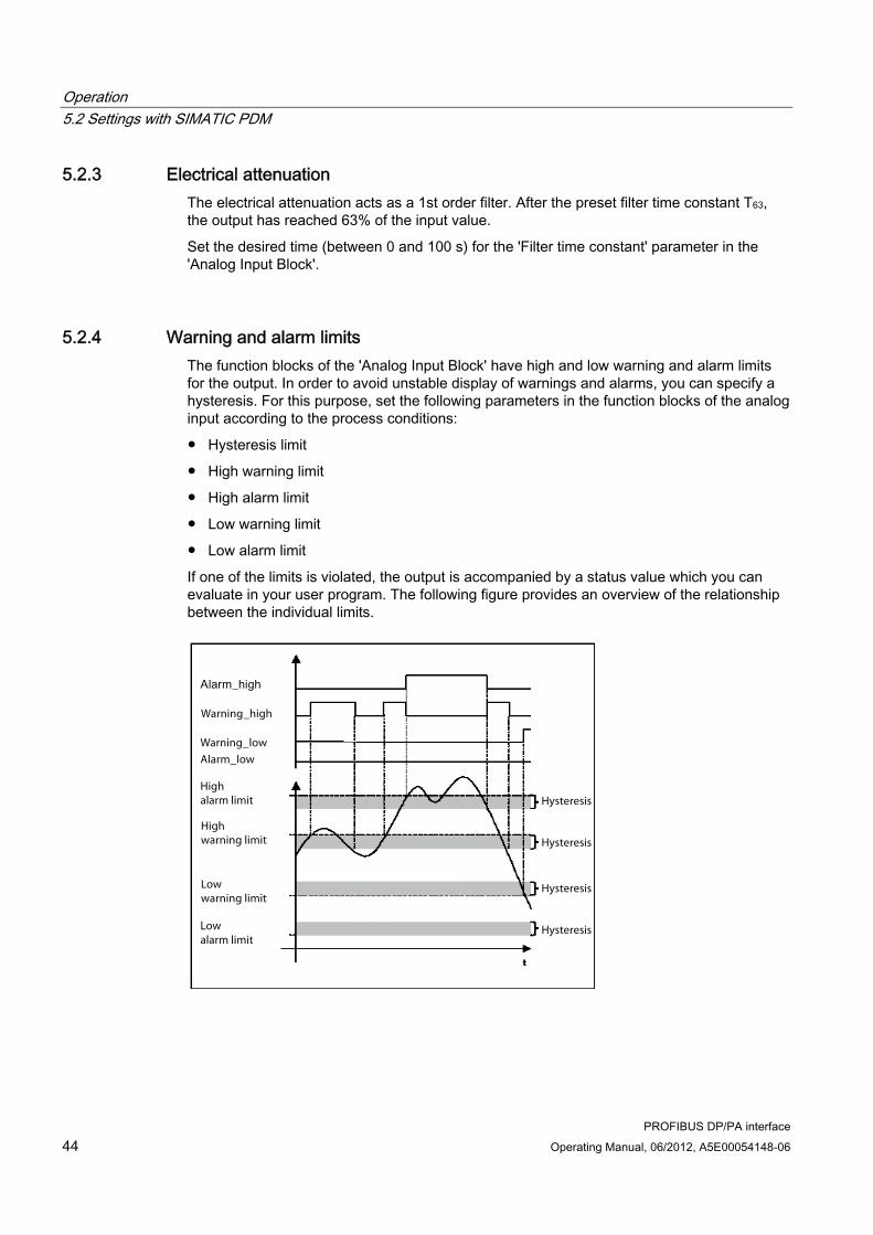
5.2.4 Warning and alarm limits The function blocks of the 'Analog Input Block' have high and low warning and alarm limits for the output. In order to avoid unstable display of warnings and alarms, you can specify a hysteresis. For this purpose, set the following parameters in the function blocks of the analog input according to the process conditions:
● Hysteresis limit
● High warning limit
● High alarm limit
● Low warning limit
● Low alarm limit
If one of the limits is violated, the output is accompanied by a status value which you can evaluate in your user program. The following figure provides an overview of the relationship between the individual limits.
Hysteresis
Hysteresis
Hysteresis
Hysteresis
Alarm_low
Warning_low
Warning_high
Highwarning limit
Lowwarning limit
Highalarm limit
Lowalarm limit

Operation 5.2 Settings with SIMATIC PDM
PROFIBUS DP/PA interface Operating Manual, 06/2012, A5E00054148-06 45
5.2.5 Response in event of failure The function blocks of the 'Analog Input Block' can adopt a preset response upon failure of the measured value block. If the output variables of the measured value block are accompanied by the "bad" status due to an error, e.g. "Bad - Sensor fault", the function blocks activate the failure response. The output is then accompanied by an "uncertain" status. An overview of the statuses can be found in section Data type DS-33 (Page 64).
Set the failure response in the function block 'Analog Input Block' as follows:
Response in event of failure Description The substitute value is applied as the output value
The predefined safety default value is output
Saving the last valid output value The last valid output value is output The incorrectly calculated measured value is at the output (failure logic switched off)
The 'bad' output value is accompanied by the status assigned to it by the measured value block
5.2.6 AUTOCAL If the appropriate option is present, the analyzers can perform a complete calibration cycle.
This calibration can be started in the Device/Calibration/Calibrate zero/AUTOCAL menu.

Operation 5.2 Settings with SIMATIC PDM
PROFIBUS DP/PA interface 46 Operating Manual, 06/2012, A5E00054148-06
5.2.7 Simulations Various simulations can be called using the 'Device -> Simulation' menu.
5.2.7.1 Simulation of an output You can use this function to provide process values for the cyclic user data traffic at the output of an analyzer using acyclic write operations. In this manner, you can check the processing of process values.
To do this, proceed as follows:
1. Select the simulation of the output
2. Set the target mode to MAN (manual)
3. Enter the desired output value, the quality, and the status
4. Transfer the settings from the program to the analyzer.
The behavior of the output can be observed, for example, in SIMATIC PDM or using a variable table (VAT in the block folder of the SIMATIC messenger).
To return to normal operation afterwards, set the target mode to 'AUTO'.
5.2.7.2 Simulation of an input Following adaptation of the measured value, you can use this function to check the value for correct implementation of the modified parameters, such as
● Monitoring of the preset process limits
● Electrical attenuation
● Response in event of failure.
To do this, proceed as follows:
1. Select the simulation of the input
2. Set the target mode to 'AUTO'
3. Select the simulation mode 'Released'
4. Enter the desired output value, the quality, and the status
5. Transfer the settings from the program to the analyzer.
You can observe the behavior of the output in SIMATIC PDM, for example.
To return to normal operation afterwards, you must switch off the simulation.

Operation 5.2 Settings with SIMATIC PDM
PROFIBUS DP/PA interface Operating Manual, 06/2012, A5E00054148-06 47
5.2.8 Reset functions Various reset functions can be called using the 'Device -> Reset' menu.
5.2.8.1 Resetting to the as-supplied state If a device has been adjusted in such a way that it can no longer perform its measuring task correctly, you can use this function to restore the parameters to the as-supplied state. Using this function, all parameters are reset to the factory settings. The PROFIBUS address is not changed in the process. The reset action is indicated by the "Cold start executed" diagnostics message. If no measured value result is available after this, the "Unsure, initial value, value constant" status is output.
This function only resets the PROFIBUS module. The factory settings of the device can only be reset using the input menu on the device itself (refer to the operating instructions for the relevant device).
Resetting the PROFIBUS module has no effect on the following objects:
● ACTIVE_RANGE
● AUTORANGE-ON
● BATCH
● CALIBRATION-DATA
● DESCRIPTOR
● DEVICE_INSTAL_DATE
● DEVICE_MESSAGE
● DEVICE_STATE
● IDENT_NUMBER_SELECTOR
● INIT_STATE
● PV_UNIT
● PV_UNIT_TEXT
● OUT
● OUT_UNIT_TEXT
● RANGE_1
● TAG_DESC

Operation 5.3 Operation with SIMATIC PDM
PROFIBUS DP/PA interface 48 Operating Manual, 06/2012, A5E00054148-06
5.2.8.2 Resetting the PROFIBUS address In the factory setting, the PROFIBUS address is preset to '126'.
If another device in your system already has the preset address 126, you can add your device to the PROFIBUS line during ongoing operation of the automation or control system. You must subsequently change the address of the newly connected device to a different value.
If you then remove a device from the PROFIBUS line, you should reset its address to 126 using this function so that you can re-integrate it into this system or another system if required.
5.3 Operation with SIMATIC PDM Parameters can be assigned and measured values monitored using the SIMATIC PDM operating program and a personal computer (PC) or programming device (PG).
You can find detailed information on this on the Internet under: SIMATIC PDM info ()

PROFIBUS DP/PA interface Operating Manual, 06/2012, A5E00054148-06 49
User data via PROFIBUS 6
The PROFIBUS PA communication protocol 3.0.1 is used as the PROFIBUS data structure for all modules. The data structures, their significance, and the functional scope are defined for PROFIBUS PA in the "PROFIBUS PA profiles". These profiles are specified in the following documents:
● PROFIBUS PA Profile for Process Control Devices / General Requirements
● PROFIBUS PA Profile for Process Control Devices / Mapping to Fieldbus
● PROFIBUS PA Profile for Process Control Devices / Data Sheet Transmitter
● PROFIBUS PA Profile for Process Control Devices / Data Sheet Analyzer
● PROFIBUS PA Profile for Process Control Devices / Data Sheet Discrete Output
These documents can be obtained from the PI (PROFIBUS International) either by post:
PROFIBUS Nutzerorganisation Haid-und-Neu-Str. 7 D-76131 Karlsruhe, Germany Tel.: +49 (0)721 / 96 58 590 Fax: +49 (0)721 / 96 58 589
or on the Internet under PROFIBUS (PI) (http://www.profibus.com)
With the user data, a distinction is made between cyclic and acyclic services. Cyclic services are used to transmit time-critical data such as measured values and statuses. Acyclic services permit querying or modification of device parameters during operation.
6.1 Device revisions PROFIBUS communication with the devices was developed in two stages. Specific device revisions and operating software must be available in order to use the complete functionality of stage 2.
The following table provides an overview of the dependency between PROFIBUS functionality and device software.

User data via PROFIBUS 6.1 Device revisions
PROFIBUS DP/PA interface 50 Operating Manual, 06/2012, A5E00054148-06
Table 6- 1 Overview of PROFIBUS device revisions for devices of Series 6/U23
Device firmware FW/HW add-on card
GSD version DD version
PDM version
U6/O6 C6 F6 C62/O64 U23 Device revision 1 with maintenance with the following functionality: Output of faults Maintenance requests as texts with help
V 4.7.0 V 1.3.0 V 1.2.0 -- V 2.13.0 V 1.6.4, all HW
V 3.0; with C6: V 3.1; with F6: V 3.2
01.01.05-014
From PDM 6.0
Device revision 2 with relay control: (supplemented by following functions) Extended command set New physical block 2 for the add-on board Cyclic services with new DO2 for setting relay outputs on the add-on card Cyclic services with reading of the binary inputs (DI 1/2) of the device
V 4.7.1 V 1.3.1 V. 1.3.1 -- V. 2.14.0 V2.0.0; HW from ES5 (PA)or ES6 (DP+PA-Ex)
SI02809C.gsd, SI02809E.gsd V. 1.0.3
02.00.00-19
6.0 with SP1;6.0 with SP2
Device revision 2, supplemented by: CALOMAT 62 and OXYMAT 64 devices
V. 4.7.3 V 1.3.2 V 1.3.2 V 0.1.6 V. 2.14.3 V. 2.0.1 As above 02.01.01-06
6.0 with SP2;6.0 with SP3
Device revision 2, supplemented by: Switching of relays on the add-on board in every device state except REMOTE
V 4.8.3 V 1.3.5 V 1.3.4 V 1.0.2 V 2.14.6 V 2.0.2 As above As above As above Device revision 2, supplemented by: ULTRAMAT 23 - zero adjustment of O2 probe corrected
As above As above
As above As above As above V 2.0.3 As above As above As above
Device revision 2, supplemented by: Expansion of ULTRAMAT 23 by H2S probe and paramagnetic O2 probe Switching of pump and internal valve of ULTRAMAT 23 in every device state except REMOTE
As above As above
As above As above V 2.14.7 V 2.0.4 As above As above As above
Starting with device revision V2.0.0, every FW add-on card is upwards-compatible with GSD and DD.
New option modules are provided with firmware of device revision 2 in the factory. However, if you wish to continue to work with device revision 1 for compatibility reasons, the relevant firmware can be ordered together with the add-on card and the firmware of level 2. An overview of the firmware modules can be found in section Firmware/retrofitting kits/spare parts packages of PROFIBUS modules (Page 78).

User data via PROFIBUS 6.2 Data profile
PROFIBUS DP/PA interface Operating Manual, 06/2012, A5E00054148-06 51
6.2 Data profile
PROFIBUS block model
Figure 6-1 Block structure of a gas analyzer with 4 block types, example with one measured value
Block structure of device versions
Function Block Device version
AI (Analog Input) DO (Digital Output) DI (Digital Input) ULTRAMAT 6 with 1 component 1 2 2 ULTRAMAT 6 with 2 components 2 2 2 ULTRAMAT 23 with 1 component 1 2 2 ULTRAMAT 23 with more than one component
See ULTRAMAT 23 table 2 2
OXYMAT 6 OXYMAT 61 OXYMAT 64
1 2 2
CALOMAT 6 CALOMAT 62
1 2 2
FIDAMAT 6 1 2 2
The Digital Input Block and the second Digital Output Block are only available with functional expansion stage (device revision) 2 starting with software version 2.0.0. Older software versions (device revision 1) are still fully operational.
With ULTRAMAT 6 and ULTRAMAT 23, the assignments to the infrared (IR) measured components are always made in ascending order starting with "1".

User data via PROFIBUS 6.2 Data profile
PROFIBUS DP/PA interface 52 Operating Manual, 06/2012, A5E00054148-06
If the ULTRAMAT 23 is used to measure oxygen (O2) and hydrogen sulfide (H2S), these always occupy the positions 3 (H2S) and 4 (O2).
ULTRAMAT 23 The following possibilities exist for ULTRAMAT 23 as a result of the measured components:
Device version IR component 1 IR component 2 IR component 3 H2S (if present) O2 (if present) 7MB2335 AI 1 ------------ ------------ AI 3 AI 4 7MB2337 AI 1 AI 2 ------------ AI 3 AI 4 7MB2338 AI 1 AI 2 AI 3 ------------ AI 4
The following slots are assigned to the Function Blocks during the configuration (see also Selection of the target configuration (Page 30)):
● AI 1 to AI 4: 1 - 4;
● DO 1: 5;
● DI 1: 6;
● DI 2: 7;
● DO 2: 8;

User data via PROFIBUS 6.3 Cyclic data transfer
PROFIBUS DP/PA interface Operating Manual, 06/2012, A5E00054148-06 53
6.3 Cyclic data transfer The address of the PROFIBUS board cannot be changed in the case of cyclic data transfer.
6.3.1 Slots for cyclic data transfer
Table 6- 2 Overview of slots for cyclic data transfer
Slot Description Parameter Slot 1 ( AI 1 ) Read measured value of component 1
(Measured value/status (Page 54)) 5 bytes = 1 float, 1 byte / Bytes 1 to 4: measured value (float) Byte 5: status according to table of PROFIBUS statuses
Slot 2 ( AI 2 ) Read measured value of component 2 (IR of U6 or U23)
Like AI 1
Slot 3 ( AI 3 ) Read measured value of component 3 (IR or H2S probe of U23)
Like AI 1
Slot 4 ( AI 4) Read measured value of component 4 (O2 probe of U23)
Like AI 1
Write Slot 5 ( DO 1 )
Start/stop AUTOCAL (Triggering AUTOCAL (Page 54))
2 bytes/ Byte 1: Bit 0 = 1: Start AUTOCAL; (bit 0 must first be = 0) Byte 1: Bit 1 = 1: Abort AUTOCAL; Byte 1: Bits 2 – 7 = 0 Byte 2: 80 Hex
Read Slot 5 ( DO 1 )
Read Autocal status (Triggering AUTOCAL (Page 54))
2 bytes/ Byte 1: Bit 0 = 1: AUTOCAL in function; Byte 1: Bits 1 – 7 = 0 Byte 2: Status (can be ignored)
Slot 6 ( DI 1 ) Read binary inputs of motherboard (Reading digital inputs (Page 56))
2 bytes/ Byte 1: Bits 0 - 7 = binary inputs 1 - 8 Byte 2: Status (can be ignored)
Slot 7 ( DI 2 ) Read binary inputs of PROFIBUS add-on card (Reading digital inputs (Page 56))
2 bytes/ Byte 1: Bits 0 - 7 = binary inputs 1 - 8 Byte 2: Status (can be ignored)
Write Slot 8 ( DO 2 )
Set relay outputs of PROFIBUS add-on card (Assigning relay outputs (Page 55))
2 bytes/ Byte 1: Bits 0 - 7 = relay outputs 1 - 8 Byte 2: 80 Hex Switching of the relays must be enabled in the device.
Read Slot 8 ( DO 2 )
Read relay outputs of PROFIBUS add-on card (Assigning relay outputs (Page 55))
2 bytes/ Byte 1: Bits 0 - 7 = relay outputs 1 - 8 Byte 2: Status (can be ignored)

User data via PROFIBUS 6.3 Cyclic data transfer
PROFIBUS DP/PA interface 54 Operating Manual, 06/2012, A5E00054148-06
6.3.2 Measured value/status Cyclic reading of the measured value and status is possible using the Analog Input Block (AI 1 ... 4). Cyclic exchange of the following user data is possible over PROFIBUS:
Parameter name Description Direction of data transfer
(from viewpoint of gas analyzer)Data type Length (bytes)
OUT Measured value and status
Output Data type DS-33 (Page 64)
5
6.3.3 Triggering AUTOCAL Cyclic triggering of AUTOCAL is possible using the Discrete Output Block 1. Cyclic transfer of the following user data to the device is possible over PROFIBUS:
Parameter name Description Direction of data transfer
(from viewpoint of gas analyzer) Data type Length
(bytes) SP_D Setpoint of function block for
AUTO mode Input Data type DS-34
(Page 66) 2
READBACK_D Acknowledgment of function block
Output Data type DS-34 (Page 66)
2
Note Wrong setting
When writing SP_D, the status must have the value '0x80'; otherwise, the setting is not accepted. Bit B01 must be set to '0' again before renewed triggering of AUTOCAL is carried out. AUTOCAL can only be started if the device is in the 'Measure' state.
Significance of the bits in the status byte with SP_D (trigger AUTOCAL):
MSB LSB 7 6 5 4 3 2 1 0 Description -- -- -- -- -- -- 1 -- Abort AUTOCAL -- -- -- -- -- -- 0 1 Trigger AUTOCAL

User data via PROFIBUS 6.3 Cyclic data transfer
PROFIBUS DP/PA interface Operating Manual, 06/2012, A5E00054148-06 55
Significance of the bits in the status byte with READBACK_D (acknowledge AUTOCAL):
MSB LSB 7 6 5 4 3 2 1 0 Description -- -- -- -- -- -- -- 1 AUTOCAL functioning -- -- -- -- -- -- -- 0 AUTOCAL not functioning
6.3.4 Assigning relay outputs The Discrete Output Block 2 is available starting with Device Revision 2 (PROFIBUS card firmware V2.0.0 and higher). In order to control the relay outputs, this function must first be activated in the device (see sections Analyzers of Series 6 (Page 39) and ULTRAMAT 23 (Page 41)).
Cyclic reading and assignment of the relay outputs of the add-on board is possible using the Discrete Output Block 2. Cyclic transfer of the following user data to the device is possible over PROFIBUS:
Parameter name Description Direction of data transfer
(from viewpoint of gas analyzer) Data type Length (bytes)
SP_D Setpoint of function block for AUTO mode
Input Data type DS-34 (Page 66)
2
READBACK_D Acknowledgment of function block
Output Data type DS-34 (Page 66)
2
Significance of the bits in the status byte with SP_D (assign relay output) and READBACK_D (read set status of relay output):
MSB LSB 7 6 5 4 3 2 1 0 Relay output 8
Relay output 7
Relay output 6
Relay output 5
Relay output 4
Relay output 3
Relay output 2
Relay output 1
When writing SP_D, the status must have the value '0x80'; otherwise, the setting is not accepted.

User data via PROFIBUS 6.3 Cyclic data transfer
PROFIBUS DP/PA interface 56 Operating Manual, 06/2012, A5E00054148-06
6.3.5 Reading digital inputs Cyclic reading of the digital inputs of the motherboard and add-on board is possible using the Discrete Input Block 1 and Discrete Input Block 2.
The Discrete Output Block 1 and 2 are only available starting with Device Revision 2 (PROFIBUS card firmware V2.0.0 and higher). 8 digital inputs are available on the add-on board. The following digital inputs are available on the motherboard:
Analyzers of Series 6 Digital inputs 1 to 6 ULTRAMAT 23 Digital inputs 1 to 3
Cyclic transfer of the following user data to the device is possible over PROFIBUS:
Parameter name Description Direction of data transfer
(from viewpoint of gas analyzer) Data type Length
(bytes) OUT_D Reading of function block Output Data type DS-34
(Page 66) 2
Significance of the bits in the status byte with OUT_D (read digital input):
Discrete Output Block 1 Digital inputs of the motherboard Discrete Output Block 2 Digital inputs of the add-on board
MSB LSB 7 6 5 4 3 2 1 0 Digital input 8 Digital input 7 Digital input 6 Digital input 5 Digital input 4 Digital input 3 Digital input 2 Digital input 1

User data via PROFIBUS 6.4 Non-cyclic data transfer
PROFIBUS DP/PA interface Operating Manual, 06/2012, A5E00054148-06 57
6.4 Non-cyclic data transfer
Commands for non-cyclic data transfer The commands shown here are only a selection of the most frequently used commands. The commands of the individual blocks required according to the PROFIBUS Profile 3.0.1 are implemented completely.
Commands for changing device-specific values and statuses can only be entered with non-coded devices. If the commands refer to a specific component (1 to 4), this must usually be specified using the slot number (slot 1 to 4).
6.4.1 Measured value commands
Table 6- 3 Overview of commands for measured value processing
Description Slot / index
Object name / block
Parameter
Read measured value of component
Slot 1 ... 4/26
OUT / AI 1 ... 4
5 bytes / Bytes 1 to 4: measured value (float); Byte 5: Status according to table in Measured value/status (Page 54)
Measured value in event of error (see Response in event of failure (Page 45))
Slot 1 ... 4/33
FSAVE_TYPE /AI 1 ... 4
1 byte / Byte = 0: measured value = substitute value FSAVE_VALUE; Byte = 1: measured value = last valid measured value;Byte = 2: measured value without influence
Substitute value in event of error Slot 1 ... 4/34
FSAVE_VALUE / AI 1 ... 4
1 Float / Default = 0.00
PROFIBUS limit (see Warning and alarm limits (Page 44)); sets bit 0 or 1 in the status (see Measured value/status (Page 54)); high alarm limit
Slot 1 ... 4/37
HI_HI_LIM / AI 1 ... 4
1 Float / The PROFIBUS limit is independent of the device-specific limits of the device menus
Low alarm limit Slot 1 ... 4/43
LO_LO_LIM / AI 1 ... 4
1 Float /
High warning limit Slot 1 ... 4/39
HI_LIM / AI 1 ... 4
1 Float /
Low warning limit Slot 1 ... 4/41
LO_LIM / AI 1 ... 4
1 Float /
Hysteresis limit Slot 1 ... 4/35
ALARM_HYS / AI 1 ... 4
1 Float / Default = 0.5 (% of largest measuring range)

User data via PROFIBUS 6.4 Non-cyclic data transfer
PROFIBUS DP/PA interface 58 Operating Manual, 06/2012, A5E00054148-06
6.4.2 Calibration commands A calibration can only be started from the device status MEASURE. The commands may therefore only be sent once. After the calibration is completed or canceled, the device returns to the MEASURE status.
Table 6- 4 Overview of calibration commands
Description Slot / Index
Object name / block
Parameter
Set calibration mode (zero or sensitivity). With a zero calibration for the ULTRAMAT 23, a calibration is carried out as with AUTOCAL with the selected IR component.
Slot 1 ... 4/ 134
RECIPE / CTB 1 ... 4
1 unsigned16 / Value= 8000 Hex: zero calibration Value = 8001 Hex: sensitivity calibration MR 1 Value = 8002 Hex: sensitivity calibration MR 2 Value = 8003 Hex: sensitivity calibration MR 3 Value = 8004 Hex: sensitivity calibration MR 4
Start/abort calibration Slot 1 ... 4/ 130
COMMAND / CTB 1 ... 4
1 unsigned16 / Value= 5: start calibration Value = 6: abort calibration
Carry out calibration; apply value
Slot 1 ... 4/ 152
CALIBRATE / CTB 1 ... 4
1 byte / Byte = 1: carry out calibration (calibration must be started beforehand)
Calibration gas setpoints of the measuring ranges
Slot 1 ... 4/ 153
STEEPNESS_ CONCENTRATION / CTB 1 ... 4
4 Float / Values 1-4: setpoints of measuring ranges 1-4
Slot 5/
25 SP_D / DO 1 2 bytes /
Byte 1: Bit 0 = 1: Start AUTOCAL; (bit 0 must first be set to 0) Byte 1: Bit 1 = 1: abort AUTOCAL Byte 2: 80 Hex
Read AUTOCAL status Slot 5/ 28
READBACK_D / DO 1
2 bytes / Byte 1: Bit 0 = 1: AUTOCAL in function; Byte 2: Status (can be ignored here)
AUTOCAL purging times Slot 5/ 85
CLEAN_TIME_ AUTOCAL_1 / DO 1
6 Float / Values 1–6: purging times of AUTOCAL sequence points 1-6 (in seconds)
Read remaining time of current AUTOCAL state
Slot 1/ 228
REMAINING_ TIME / PB2
3 bytes / Byte 1: device state according to table 'Device statuses' (see Parameter tables (Page 62)) Bytes 2 to 3: (unsigned16) remaining time of current state in s The value of the remaining time is updated approximately every 8 seconds.

User data via PROFIBUS 6.4 Non-cyclic data transfer
PROFIBUS DP/PA interface Operating Manual, 06/2012, A5E00054148-06 59
Description Slot / Index
Object name / block
Parameter
Read number of current device sequence point
Slot 5/ 82
ACTUAL_SEQ / DO 1
1 Byte / Byte = see table 'Device sequence points' in section Parameter tables (Page 62) Updating of the value may be delayed by up to 60 seconds. From PROFIBUS software version 2.00.04 onwards, this delay is approximately 8 seconds.
Start AUTOCAL check once/abort AUTOCAL check
Slot 5 / 90
AUTOCAL-CHECK / DO 1
1 byte / Byte = 1: start Autocal check; Byte = 0: abort Autocal check
6.4.3 Commands for device hardware
Table 6- 5 Overview of commands for device hardware
Description Slot/ Index
Object name / block
Parameter
Read digital inputs of the motherboard
Slot 6/ 26
OUT_D / DI 1 2 bytes / Byte 1: Bits 0 - 7 = binary inputs 1 - 8 Byte 2: Status (can be ignored here)
Read digital inputs of PROFIBUS add-on card
Slot 7/ 26
OUT_D / DI 2 2 bytes / Byte 1: Bits 0 - 7 = binary inputs 1 - 8 Byte 2: Status (can be ignored here)
Switch relay outputs of PROFIBUS add-on card
Slot 8/ 25
SP_D / DO 2 2 bytes / Byte 1: Bits 0 - 7 = relay outputs 1 - 8 Byte 2: 80 Hex Switching of the relays must be enabled in the device.
Read relay outputs of the motherboard
Slot 6/ 95
RELAY_ READBACK_D / DI 1
2 bytes / Byte 1: Bits 0 - 7 = relay outputs 1 - 8 Byte 2: Status (can be ignored here)
Read relay outputs of PROFIBUS add-on card
Slot 8/ 28
READBACK / DO 2
2 bytes / Byte 1: Bits 0 - 7 = relay outputs 1 - 8 Byte 2: Status (can be ignored here)
Switch pump (ULTRAMAT 23 only)
Slot 1/ 225
SWITCH_ FUNCTION / PB 2
3 bytes / Byte 1 = 0; Byte 2 = 11; Byte 3 = 1 (pump on) or 0 (pump off). A change in the device status can also change the status of the pump.
Switch internal solenoid valve (ULTRAMAT 23 only)
Slot 1/ 225
SWITCH_ FUNCTION / PB 2
3 bytes / Byte 1 = 0; Byte 2 = 6; Byte 3 = 1 (solenoid valve on) or 0 (solenoid valve off). A change in the device status can also change the status of the solenoid valve.

User data via PROFIBUS 6.4 Non-cyclic data transfer
PROFIBUS DP/PA interface 60 Operating Manual, 06/2012, A5E00054148-06
Description Slot/ Index
Object name / block
Parameter
Read switching status of pump (ULTRAMAT 23 only)
Slot 1/ 222
CHANNEL_ FUNCTION / PB2
4 bytes / Byte 2: bit 1 = 1 (pump on) or 0 (pump off)
Read switching status of sample gas pressure switch
Slot 1/ 222
CHANNEL_ FUNCTION / PB2
4 bytes / Byte 1: bit 3 = 1 (pressure switch fitted and pressure/flow present) Function starting with U6/O6 software version 4.8.4 and U23 software version 2.14.07
Read switching status of reference gas pressure switch (U6, O6 only)
Slot 1/ 222
CHANNEL_ FUNCTION / PB2
4 bytes / Byte 1: bit 3 = 1 (pressure switch fitted and pressure present) Function starting with U6/O6 software version 4.8.4.
Read switching status of valves Slot 1/ 229
VALVES / PB2 1 byte / Bit 7 = 1; Bit 0 = 1: sample gas valve open Bit 1 = 1: zero gas valve open Bit 2 = 1: calibration gas valve 1 open Bit 1 = 3: calibration gas valve 2 open Bit 1 = 4: calibration gas valve 3 open Bit 1 = 5: calibration gas valve 4 open

User data via PROFIBUS 6.4 Non-cyclic data transfer
PROFIBUS DP/PA interface Operating Manual, 06/2012, A5E00054148-06 61
6.4.4 General commands
Table 6- 6 Overview of general commands
Description Slot/ Index
Object name / block
Parameter
Read current device faults Slot 1/ 217
ERRORS / PB 2 4 bytes / Byte 1: Bits 0 - 7 = errors 1 - 8 Byte 2: Bits 0 - 7 = errors 9 - 16 Byte 3: Bits 0 - 7 = errors 17 - 24 Byte 4: Bits 0 - 7 = errors 25 – 31 The significance of the error numbers is explained in section Structure of the error messages (Page 63).
Read current device maintenance requests
Slot 1/ 218
WARNINGS / PB 2
2 bytes / Byte 1: Bits 0 - 7 = maintenance requests 1 - 8 Byte 2: Bits 0 - 7 = maintenance requests 9 – 16 The significance of the maintenance requests is explained in section Structure of the error messages (Page 63).
Read device status Slot 1/
226 CHANNEL_ STATE / PB2
1 Byte / Byte = device status according to table 'Device statuses' in section Parameter tables (Page 62)
Read device sequence point
Slot 5/ 82
ACTUAL_SEQ / DO1
1 unsigned 8 / Value = device sequence point according to table 'Device sequence points' in section (Page 62).
Measuring range 1 Slot 1 ...4/
92 RANGE_1 / TB 1 ... 4
2 Float / Value 1: start-of-scale value of measuring range Value 2: full-scale value of measuring range
Measuring ranges 2 to 4 Slot 1 ...4/ 93 ... 95
RANGE_2 ... RANGE_4 / TB 1 ... 4
Parameters as with RANGE_1
Read diagnostics value of analog current input (only devices of Series 6)
Slot 1/ 240
DIAG_VALUES_4 / PB2
8 Float / Values 1 to 4: ELAN h, 7 for components 1 to 4 (analog current input with Series 6) Values 5 to 8: ELAN h, 8 for components 1 to 4 (signal vector with Series 6)

User data via PROFIBUS 6.5 Parameter description
PROFIBUS DP/PA interface 62 Operating Manual, 06/2012, A5E00054148-06
6.5 Parameter description
6.5.1 Parameter tables The 'Device statuses' and 'Device sequence points' parameters described in this section can assume the values listed in the following tables .
Table 6- 7 Device statuses
Value Description Comments 1 Warming-up 2 Pause 3 Standby 4 Measure 5 Calibrate zero point / AUTOCAL with CAL button with ULTRAMAT
23
6 Calibrate slope of a component 14 AUTOCAL 16 Calibrate zero point of O2 probe Only ULTRAMAT 23 21 AUTOCAL check Only analyzers of Series 6
Table 6- 8 Device sequence points
Value Description Comments 1 No sequence 2 AUTOCAL - zero gas 1 Only analyzers of Series 6 3 AUTOCAL - zero gas 2 Only analyzers of Series 6 4 AUTOCAL - calibration gas 1 Only analyzers of Series 6 5 AUTOCAL - calibration gas 2 Only analyzers of Series 6 6 AUTOCAL - calibration gas 3 Only analyzers of Series 6 7 AUTOCAL - calibration gas 4 Only analyzers of Series 6 8 AUTOCAL - sample gas purging Only analyzers of Series 6 9 AUTOCAL - sample gas intermediate operation Only analyzers of Series 6 10 AUTOCAL - signaling contact Only analyzers of Series 6 11 AUTOCAL - zero gas component 2 Only analyzers of Series 6 12 AUTOCAL - calibration gas 1 component 2 Only analyzers of Series 6 13 AUTOCAL - calibration gas 2 component 2 Only analyzers of Series 6 14 AUTOCAL - calibration gas 3 component 2 Only analyzers of Series 6 15 AUTOCAL - calibration gas 4 component 2 Only analyzers of Series 6 100 H2S protection sequence 'Measure' Only ULTRAMAT 23 101 H2S protection sequence 'Purge' Only ULTRAMAT 23 102 H2S protection sequence 'Continuous purging' Only ULTRAMAT 23 110 H2S probe 'Purge' Only ULTRAMAT 23 111 H2S probe 'Pre-purge' Only ULTRAMAT 23

User data via PROFIBUS 6.5 Parameter description
PROFIBUS DP/PA interface Operating Manual, 06/2012, A5E00054148-06 63
6.5.2 Structure of the error messages
Faults Error messages are structured as follows in the ERRORS parameter:
Byte 0 Bit 8 7 6 5 4 3 2 1 Fault S8 S7 S6 S5 S4 S3 S2 S1 Byte 1 Bit 8 7 6 5 4 3 2 1 Fault S16 S15 S14 S13 S12 S11 S10 S9 Byte 2 Bit 8 7 6 5 4 3 2 1 Fault S24 S23 S22 S21 S20 S19 S18 S17 Byte 3 Bit 8 7 6 5 4 3 2 1 Fault S32 S31 S30 S29 S28 S27 S26 S25
The meanings of S1 to S32 are explained in the section 'Diagnostics'.
Maintenance requests Maintenance requests are structured as follows in the WARNINGS parameter:
Byte 0 Bit 8 7 6 5 4 3 2 1 Maintenance request W8 W7 W6 W5 W4 W3 W2 W1 Byte 1 Bit 8 7 6 5 4 3 2 1 Maintenance request W16 W15 W14 W13 W12 W11 W10 W9
The meanings of W1 to W16 are described in the section 'Diagnostics'.

User data via PROFIBUS 6.5 Parameter description
PROFIBUS DP/PA interface 64 Operating Manual, 06/2012, A5E00054148-06
6.5.3 Data type DS-33
Structure Byte 1 Byte 2 Byte 3 Byte 4 Byte 5 Analog value in IEEE floating point Status Exponent Fraction MSB
A status byte is transmitted synchronously in addition to each of the measured values in the DS-33 data structure. This byte provides an indication of the quality of the associated measured value.
Status byte The status byte is structured as follows:
MSB 7 6 5 4 3 2 1 0 Description Quality Substatus Limits 0 0 bad Bad 0 1 uncertain Uncertain 1 0 good Good 1 1
The substatus has different meanings depending on the quality.
good (cascaded) Good (cascaded)
0 0 O.K. OK 0 1 low limited Low PROFIBUS limit
violated 1 0 high limited High PROFIBUS limit
violated 1 1 constant Constant value

User data via PROFIBUS 6.5 Parameter description
PROFIBUS DP/PA interface Operating Manual, 06/2012, A5E00054148-06 65
Status codes
Table 6- 9 Status codes with 'Bad quality' status
Dec Hex Cause(s) Measure(s) 11 0B Component missing Change configuration,
install device which contains this component 12 0C Device signals a fault Define fault more precisely using SIMATIC PDM
Replace device 31 1F Device out of service
(last valid value is applied as substitute value)
Depending on the parameter assignment, the device has a certain status which requires a procedure appropriate to the status. Set operating mode 'AUTO'
Table 6- 10 Status codes with 'Uncertain quality' status
Dec Hex Cause(s) Measure(s) 64 40 Device signals a functional check Warming-up phase
AUTOCAL Local service (device coded; in input menu)
71 47 Measured value bad (last valid value)
Define fault more precisely using SIMATIC PDM Replace device
75 4B Measured value bad (substitute value) Define fault more precisely using SIMATIC PDM Replace device
79 4F The initial value appears following switch-on
Reject measured value
80 50 Measured value outside measuring range Define fault more precisely using SIMATIC PDM Ambient temperature too high
Table 6- 11 Status codes with 'Good quality'
Dec Hex Cause(s) Measure(s) 128 80 Normal operation, everything OK Measured values can be evaluated without restriction 132 84 Active block alarm,
parameter has been changed Message disappears after approximately 10 s
137 89 PROFIBUS low warning limit violated Check/change in the user program 138 8A PROFIBUS high warning limit violated Check/change in the user program 141 8D PROFIBUS low alarm limit violated Check/change in the user program 142 8E PROFIBUS high alarm limit violated Check/change in the user program 164 A4 Device signals a maintenance request Define maintenance request more precisely using SIMATIC
PDM
You can find a detailed description of data type DS-33 and the associated status byte under 'PROFIBUS-PA Profile for Process Control Devices / General Requirements'.

User data via PROFIBUS 6.5 Parameter description
PROFIBUS DP/PA interface 66 Operating Manual, 06/2012, A5E00054148-06
6.5.4 Data type DS-34
Structure Byte 1 Byte 2 Digital value/setpoint Status
Status codes
Table 6- 12 Status byte
MSB LSB Description Bit 7 Bit 6 Bit 5 Bit 4 Bit 3 Bit 2 Bit 1 Bit 0 The significance of the individual bits depends
on the parameter, and is therefore described there.
6.5.5 Generic station description The generic station descriptions (GSD) for PROFIBUS DP/PA are required for cyclic data transfer. These can be found on the Internet at SIEMENS Product Support Automation using the search term "PROFIBUS GSD files: PA" or the link: GSD (generic station description) BR 6 (http://support.automation.siemens.com/WW/llisapi.dll?aktprim=100&lang=en&referer=%2fWW%2f&func=cslib.cssearch&nodeid0=10807001&viewreg=WW&siteid=csius&extranet=standard&groupid=4000002&objaction=cssearch&content=adsearch%2Fadsearch%2Easpx) and downloaded from there
Navigate on this site to the tab 'PROFIBUS GSD files: PA' and open this by double-clicking. You can find all available generic station descriptions there.
The following GSD files are applicable for analyzers of Series 6 and the ULTRAMAT 23:
● Dev.Rev. 1:
– Siem809e.gsg/e/f/i/s (6 KB each) for DP in English/German/French/Italian/Spanish
– Siem809c.gsg/e/f/i/s (6 KB each) for PA in English/German/French/Italian/Spanish
– sie809cn.bmp (5 kB); Bitmap
● Dev.Rev. 2:
– SIO2809e.gsd/g/e/f/i/s for DP and SIO2809c.gsd/g/e/f/i/s for PA
– SIE809Cn.bmp (4 kB); Bitmap

Alarm, error, and system messages
PROFIBUS DP/PA interface Operating Manual, 06/2012, A5E00054148-06 67
Alarm, error, and system messages 77.1 Status and error messages with SIMATIC PDM
Linking the devices using PC software such as SIMATIC PDM allows error diagnostics to be carried out. Current faults and maintenance requests can then be evaluated using SIMATIC PDM, menu "Object properties / Diagnostics". These messages are displayed in plain text, thus facilitating appropriate troubleshooting measures.

Alarm, error, and system messages 7.2 Diagnostics information
PROFIBUS DP/PA interface 68 Operating Manual, 06/2012, A5E00054148-06
7.2 Diagnostics information The following tables show the assignment of device error messages/maintenance requests to the diagnostics bits in the respective physical block:
7.2.1 ULTRAMAT 6
Table 7- 1 ULTRAMAT 6 diagnostics information
Fault (F) Maint. request (M)
Description Diagnosticsbit/byte
Diagnostics bit name
S1 Parameter memory 1 / 4 2 / 2
DIA_MEM_CHKSUM DIA_CONF_INVAL
S2 Chopper motor faulty 1 / 1 DIA_HW_MECH S3 Microflow sensor 1 / 1
1 / 5 DIA_HW_MECH DIA_MEASUREMENT
S4 External fault 1 / 1 DIA_HW_MECH S5 Receiver chamber temperature 1 / 1 DIA_HW_MECH S6 Field device heating is defective 1 / 0 DIA_HW_ELECTR S8 Pressure sensor signal 2 / 1 DIA_SUPPLY S10 24h RAM check 1 / 4
2 / 2 DIA_MEM_CHKSUM DIA_CONF_INVAL
S11 Reference gas pressure too low 2 / 1 DIA_SUPPLY S12 Power supply 2 / 1 DIA_SUPPLY S13 Hardware/line frequency 2 / 1
1 / 0 DIA_SUPPLY DIA_HW_ELECTR
S14 Measured value > full-scale value of characteristic 1 / 1 1 / 5
DIA_HW_MECH DIA_MEASUREMENT
S15 Calibration aborted 1 / 5 DIA_MEASUREMENT S16 Sample gas pressure too low 2 / 1 DIA_SUPPLY W1 Calibration tolerance exceeded 2 / 5 DIA_MAINTENANCE W2 Reserve for zero adjustment < 20% 2 / 5 DIA_MAINTENANCE W3 Signal voltage adjustment too low 2 / 5 DIA_MAINTENANCE W4 Set clock 2 / 5 DIA_MAINTENANCE W5 Microflow sensor 2 / 5 DIA_MAINTENANCE W6 Temperature sensor of LCD display 2 / 5 DIA_MAINTENANCE W7 Receiver chamber temperature > 70 °C 2 / 5 DIA_MAINTENANCE W9 External maintenance request 2 / 5 DIA_MAINTENANCE W10 AUTOCAL check deviation 2 / 5 DIA_MAINTENANCE

Alarm, error, and system messages 7.2 Diagnostics information
PROFIBUS DP/PA interface Operating Manual, 06/2012, A5E00054148-06 69
7.2.2 CALOMAT 6
Table 7- 2 CALOMAT 6 diagnostics information
Fault (F) Maint. request (M)
Description Diagnostics bit/byte
Diagnostics bit name
S1 Parameter memory 1 / 4 2 / 2
DIA_MEM_CHKSUM DIA_CONF_INVAL
S4 External fault 1 / 1 DIA_HW_MECH S5 Temperature TCD 1 / 1 DIA_HW_MECH S10 24h RAM check 1 / 4
2 / 2 DIA_MEM_CHKSUM DIA_CONF_INVAL
S12 Power supply 2 / 1 DIA_SUPPLY S13 Hardware/line frequency 2 / 1
1 / 0 DIA_SUPPLY DIA_HW_ELECTR
S14 Measured value > full-scale value of characteristic 1 / 1 1 / 5
DIA_HW_MECH DIA_MEASUREMENT
S15 Calibration aborted 1 / 5 DIA_MEASUREMENT W1 Calibration tolerance exceeded 2 / 5 DIA_MAINTENANCE W4 Set clock 2 / 5 DIA_MAINTENANCE W6 Temperature sensor of LCD display 2 / 5 DIA_MAINTENANCE W9 External maintenance request 2 / 5 DIA_MAINTENANCE W10 AUTOCAL check deviation 2 / 5 DIA_MAINTENANCE

Alarm, error, and system messages 7.2 Diagnostics information
PROFIBUS DP/PA interface 70 Operating Manual, 06/2012, A5E00054148-06
7.2.3 OXYMAT 6 and OXYMAT 61
Table 7- 3 OXYMAT 6 and OXYMAT 61 diagnostics information
Fault (F) Maint. request (M)
Description Diagnosticsbit/byte
Diagnostics bit name
S1 Parameter memory 1 / 4 2 / 2
DIA_MEM_CHKSUM DIA_CONF_INVAL
S2 Magnetic field supply faulty
1 / 1 DIA_HW_MECH
S3 Microflow sensor 1 / 1 1 / 5
DIA_HW_MECH DIA_MEASUREMENT
S4 External fault 1 / 1 DIA_HW_MECH S5 Temperature of analyzer section 1 / 1 DIA_HW_MECH S6 Field device heating is defective 1 / 0 DIA_HW_ELECTR S7 Temperature of measuring head outside tolerance 1 / 1 DIA_HW_MECH S8 Pressure sensor signal 2 / 1 DIA_SUPPLY S9 Signal too high 1 / 5 DIA_ MEASUREMENT S10 24h RAM check 1 / 4
2 / 2 DIA_MEM_CHKSUM DIA_CONF_INVAL
S11 Reference gas supply failed 2 / 1 DIA_SUPPLY S12 Power supply 2 / 1 DIA_SUPPLY S13 Hardware/line frequency 2 / 1
1 / 0 DIA_SUPPLY DIA_HW_ELECTR
S14 Measured value > full-scale value of characteristic 1 / 1 1 / 5
DIA_HW_MECH DIA_MEASUREMENT
S15 Calibration aborted 1 / 5 DIA_MEASUREMENT S16 Sample gas pressure too low 2 / 1 DIA_SUPPLY W1 Calibration tolerance exceeded 2 / 5 DIA_MAINTENANCE W2 Zero signal voltage too high 2 / 5 DIA_MAINTENANCE W3 Sensitivity signal voltage too low 2 / 5 DIA_MAINTENANCE W4 Set clock 2 / 5 DIA_MAINTENANCE W5 Microflow sensor
2 / 5 DIA_MAINTENANCE
W6 Temperature sensor of LCD display 2 / 5 DIA_MAINTENANCE W7 Analyzer section temperature > 70 °C 2 / 5 DIA_MAINTENANCE W8 Temperature of measuring head outside ±3 °C 2 / 5 DIA_MAINTENANCE W9 External maintenance request 2 / 5 DIA_MAINTENANCE W10 AUTOCAL check deviation 2 / 5 DIA_MAINTENANCE

Alarm, error, and system messages 7.2 Diagnostics information
PROFIBUS DP/PA interface Operating Manual, 06/2012, A5E00054148-06 71
7.2.4 ULTRAMAT 23
Table 7- 4 ULTRAMAT 23 diagnostics information
Fault (F) Maint. request (M)
Description Diagnostics bit/byte
Diagnostics bit name
S1 Measured value of channel 1 outside tolerance 1 / 5 DIA_MEASUREMENT S2 Measured value of channel 2 outside tolerance 1 / 5 DIA_MEASUREMENT S3 Measured value of channel 3 outside tolerance 1 / 5 DIA_MEASUREMENT S4 O2 measured value outside tolerance 1 / 5 DIA_MEASUREMENT S5 Line voltage outside tolerance 2 / 1 DIA_SUPPLY S6 Device temperature outside tolerance 1 / 1 DIA_HW_MECH S7 Atmospheric pressure outside tolerance 2 / 1 DIA_SUPPLY S8 No flow during measurement process 2 / 1 DIA_SUPPLY S9 No temperature comparison performed 1 / 7 DIA_INIT_ERR S10 No flow during AUTOCAL 2 / 1 DIA_SUPPLY S11 O2 measured value too low 1 / 1
1 / 5 DIA_HW_MECH DIA_MEASUREMENT
S12 Analog current output faulty 1 / 0 DIA_HW_ELECTR S13 Total error of all IR channels 1 / 1
1 / 5 DIA_HW_MECH DIA_MEASUREMENT
S14 Channel component error 1 / 1 DIA_HW_MECH S15 AUTOCAL drift too large 2 / 0 DIA_ZERO_ERR S16 EEPROM error 1 / 4
2 / 2 DIA_MEM_CHKSUM DIA_CONF_INVAL
S20 Channel 1 not calibrated 1 / 7 DIA_INIT_ERR S21 Channel 2 not calibrated 1 / 7 DIA_INIT_ERR S22 Channel 3 not calibrated 1 / 7 DIA_INIT_ERR S23 Source voltage outside tolerance 1 / 0 DIA_HW_ELECTR S24 Bridge supply voltage outside tolerance 1 / 0 DIA_HW_ELECTR S25 Bridge half-voltage outside tolerance 1 / 0 DIA_HW_ELECTR S26 Lockin error 1 / 0 DIA_HW_ELECTR S27 External fault 1 / 1 DIA_HW_MECH S28 Protection function of H2S sensor 1 / 1 DIA_HW_MECH S29 Zero point of H2S sensor outside tolerance 1 / 1 DIA_HW_MECH S30 Sensitivity of H2S sensor too low 1 / 1 DIA_HW_MECH S31 Sensitivity of O2 sensor too low 1 / 1 DIA_HW_MECH S32 External ADC error 1 / 0 DIA_HW_ELECTR W1 AUTOCAL drift too large 2 / 5 DIA_MAINTENANCE W2 O2 sensor 2 / 5 DIA_MAINTENANCE W3 LCD temperature outside tolerance 2 / 5 DIA_MAINTENANCE W4 External maintenance request 2 / 5 DIA_MAINTENANCE W5 H2S sensor 2 / 5 DIA_MAINTENANCE

Alarm, error, and system messages 7.2 Diagnostics information
PROFIBUS DP/PA interface 72 Operating Manual, 06/2012, A5E00054148-06
7.2.5 FIDAMAT 6
Table 7- 5 FIDAMAT 6 diagnostics information
Fault (F) Maint. request (M)
Description Diagnosticsbit/byte
Diagnostics bit name
S1 Parameter memory 1 / 4 2 / 2
DIA_MEM_CHKSUM DIA_CONF_INVAL
S2 Pump does not start up 1 / 1 2 / 1
DIA_HW_MECH DIA_SUPPLY
S3 Flame does not ignite 1 / 0 DIA_HW_ELECTR S4 External fault 1 / 1 DIA_HW_MECH S5 Oven temperature 1 / 0 DIA_HW_ELECTR S6 Catalyst temperature 1 / 0 DIA_HW_ELECTR S7 Flame temperature 1 / 0 DIA_HW_ELECTR S8 Combustion air/gas pressure 2 / 1 DIA_SUPPLY S9 Heater has switched off 1 / 0 DIA_HW_ELECTR S10 24h RAM check 1 / 4
2 / 2 DIA_MEM_CHKSUM DIA_CONF_INVAL
S12 Power supply 2 / 1 DIA_SUPPLY S13 Hardware/line frequency 2 / 1
1 / 0 DIA_SUPPLY DIA_HW_ELECTR
S14 Measured value > full-scale value of characteristic 1 / 1 1 / 5
DIA_HW_MECH DIA_MEASUREMENT
S15 Calibration aborted 1 / 5 DIA_MEASUREMENT W1 Calibration tolerance exceeded 2 / 5 DIA_MAINTENANCE W4 Set clock 2 / 5 DIA_MAINTENANCE W5 Combustion air/gas pressure 2 / 5 DIA_MAINTENANCE W6 Temperature sensor of LCD display 2 / 5 DIA_MAINTENANCE W7 Physical unit/electronics temperature 2 / 5 DIA_MAINTENANCE W8 Flame off 2 / 5 DIA_MAINTENANCE W9 External maintenance request 2 / 5 DIA_MAINTENANCE W10 AUTOCAL check deviation 2 / 5 DIA_MAINTENANCE

Alarm, error, and system messages 7.2 Diagnostics information
PROFIBUS DP/PA interface Operating Manual, 06/2012, A5E00054148-06 73
7.2.6 CALOMAT 62
Table 7- 6 CALOMAT 62 diagnostics information
Fault (F) Maint. request (M)
Description Diagnostics bit/byte
Diagnostics bit name
S1 Parameter memory 1 / 4 2 / 2
DIA_MEM_CHKSUM DIA_CONF_INVAL
S4 External fault 1 / 1 DIA_HW_MECH S5 Temperature of analyzer section 1 / 1 DIA_HW_MECH S6 Heating is defective 1 / 0 DIA_HW_ELECTR S9 Signal outside of limits 1 / 5 DIA_MEASUREMENT S10 24h RAM check 1 / 4
2 / 2 DIA_MEM_CHKSUM DIA_CONF_INVAL
S12 Power supply 2 / 1 DIA_SUPPLY S13 Hardware/line frequency 2 / 1
1 / 0 DIA_SUPPLY DIA_HW_ELECTR
S14 Measured value > full-scale value of characteristic 1 / 1 1 / 5
DIA_HW_MECH DIA_MEASUREMENT
S15 Calibration aborted 1 / 5 DIA_MEASUREMENT W1 Calibration tolerance exceeded 2 / 5 DIA_MAINTENANCE W4 Set clock 2 / 5 DIA_MAINTENANCE W6 Temperature sensor of LCD display 2 / 5 DIA_MAINTENANCE W7 Heating outside ±5 °C 2 / 5 DIA_MAINTENANCE W9 External maintenance request 2 / 5 DIA_MAINTENANCE W10 AUTOCAL check deviation 2 / 5 DIA_MAINTENANCE

Alarm, error, and system messages 7.2 Diagnostics information
PROFIBUS DP/PA interface 74 Operating Manual, 06/2012, A5E00054148-06
7.2.7 OXYMAT 64
Table 7- 7 OXYMAT 64 diagnostics information
Fault (F) Maint. request (M)
Description Diagnosticsbit/byte
Diagnostics bit name
S1 Parameter memory 1 / 4 2 / 2
DIA_MEM_CHKSUM DIA_CONF_INVAL
S4 External fault 1 / 1 DIA_HW_MECH S5 Temperature of analyzer section 1 / 1 DIA_HW_MECH S8 Pressure sensor signal 2 / 1 DIA_SUPPLY S10 24h RAM check 1 / 4
2 / 2 DIA_MEM_CHKSUM DIA_CONF_INVAL
S11 Purging gas supply failed 2 / 1 DIA_SUPPLY S12 Power supply 2 / 1 DIA_SUPPLY S13 Hardware/line frequency 2 / 1
1 / 0 DIA_SUPPLY DIA_HW_ELECTR
S14 Measured value > full-scale value of characteristic 1 / 1 1 / 5
DIA_HW_MECH DIA_MEASUREMENT
S15 Calibration aborted 1 / 5 DIA_MEASUREMENT S16 Sample gas pressure too low 2 / 1 DIA_SUPPLY W1 Calibration tolerance exceeded 2 / 5 DIA_MAINTENANCE W4 Set clock 2 / 5 DIA_MAINTENANCE W6 Temperature sensor of LCD display 2 / 5 DIA_MAINTENANCE W9 External maintenance request 2 / 5 DIA_MAINTENANCE W10 AUTOCAL check deviation 2 / 5 DIA_MAINTENANCE

Alarm, error, and system messages 7.2 Diagnostics information
PROFIBUS DP/PA interface Operating Manual, 06/2012, A5E00054148-06 75
7.2.8 Display of quality status in SIMATIC PDM In the event of a device fault (S1-S32), the quality status is set as follows:
Response in event of failure (see section Response in event of failure (Page 45))
Last valid measured value Substitute value Calculated value
Status Coding Symbol Coding Symbol Coding Symbol Bad, device fault 0x44-0x47
0x48-0x4B
0x0C
In the event of a device maintenance request (W1-W13), the quality status is set as follows:
Response in event of failure (see section Response in event of failure (Page 45))
Last valid measured value Substitute value Calculated value
Status Coding Symbol Coding Symbol Coding Symbol Good, maintenance request 0xA4
0x4A
0x4A
With the device status ‘Functional check’, the quality status is set as follows:
Status Coding PDM symbol Symbol Uncertain, non-specific 0x40


PROFIBUS DP/PA interface Operating Manual, 06/2012, A5E00054148-06 77
Maintenance and troubleshooting 88.1 Possible operating problems
The following table lists various problems and information on correcting them.
Description of problem Possible cause Measure for checking Described in section PROFIBUS menu in the device cannot be accessed
PROFIBUS board is not detected
Check whether the ribbon cable of the PROFIBUS board is connected to the motherboard. If this is the case, replace the PROFIBUS board.
Parameter assignment on the device (Page 39)
No PROFIBUS connection PROFIBUS address incorrect
Check PROFIBUS address in device Parameter assignment on the device (Page 39)
PROFIBUS write and set commands are not possible
Device is coded Check code display in the device main menu
Calibration cannot be started Device is not in MEASURE status
Check status display in the device main menu
PROFIBUS commands deviate from the description
ID number is not 1 Check whether the ID number in the device is set to 1
Parameter assignment on the device (Page 39)
PROFIBUS measured value is 'frozen' even though the device measured value is current.
Set device fault activates the PROFIBUS failure response
Check the failure response (Object FSAVE_TYPE) setting
Response in event of failure (Page 45)
Device is coded -> functional check
Check code display in the device main menu
PROFIBUS status does not the value "good" (80H) even though a device fault or maintenance request is not present
PROFIBUS limits active Check whether appropriate PROFIBUS limits (Objects HI_HI_LIM and LO_LO_LIM) have been selected
Warning and alarm limits (Page 44)
Measured value via PROFIBUS does not correspond to the value displayed on the device
Incorrect setting of output scaling
Check PROFIBUS parameters for scaling
Adjusting to a desired process value (Page 43)
Relays of the PROFIBUS board cannot be remote-controlled
Relays of the PROFIBUS board have not been enabled for remote control operation
Check whether the "Relay by PB" parameter in the device is set to "On"
Parameter assignment on the device (Page 39)
The PROFIBUS module is maintenance-free

Maintenance and troubleshooting 8.2 Spare parts
PROFIBUS DP/PA interface 78 Operating Manual, 06/2012, A5E00054148-06
8.2 Spare parts
8.2.1 Firmware/retrofitting kits/spare parts packages of PROFIBUS modules If it is necessary to replace the firmware of the PROFIBUS option module because of further developments, the flash EEPROM of the module (component on base) must be replaced.
The firmware of device revision 1 is only available as part of the spare parts packages/retrofitting kits. (see section Device revisions (Page 49))
The latest firmware of device revision 2 can be ordered as a spare part from CSC Haguenau (see section Return delivery (Page 83)). You can find the valid order number for your device in the following table.
Module type Item no. of module Order no. of retrofitting kit/spare parts package PROFIBUS-DP A5E00019145 A5E00057312 (rack-mounted analyzer Series 6; 1-channel analyzer)
A5E00057314 (rack-mounted analyzer Series 6; 2-channel analyzer) A5E00057318 (field device Series 6) A5E00057159 (ULTRAMAT 23)
PROFIBUS-PA A5E00034504 A5E00057307 (rack-mounted analyzer Series 6; 1-channel analyzer) A5E00057310 (rack-mounted analyzer Series 6; 2-channel analyzer) A5E00057315 (field device Series 6) A5E00056834 (ULTRAMAT 23)
PROFIBUS-PA Ex i A5E00015899 A5E00057317 (field device Series 6)
See also Fitting or retrofitting the add-on board (Page 21)

Maintenance and troubleshooting 8.2 Spare parts
PROFIBUS DP/PA interface Operating Manual, 06/2012, A5E00054148-06 79
8.2.2 Firmware of basic devices When retrofitting an analyzer with the PROFIBUS option or when changing one of the firmware option modules, it may be necessary to carry out updating (see section 3.1 Device versions):
The following table provides an overview of the order numbers for the firmware of your analyzer:
ULTRAMAT 6 FIDAMAT 6E/G Language Order number Language Order number German C79451-A3478-S501 German A5E00223093/A5E00409885English C79451-A3478-S502 English A5E00223146/A5E00409929French C79451-A3478-S503 French A5E00223149/A5E00409947Spanish C79451-A3478-S504 Spanish A5E00223152/A5E00409962Italian C79451-A3478-S505 Italian A5E00223155/A5E00409966 OXYMAT 6 and OXYMAT 61 OXYMAT 64 German C79451-A3480-S501 German A5E00789705 English C79451-A3480-S502 English A5E00789706 French C79451-A3480-S503 French A5E00789707 Spanish C79451-A3480-S504 Spanish A5E00789708 Italian C79451-A3480-S505 Italian A5E00789709 CALOMAT 6 CALOMAT 62 German A5E00092676 German A5E00789689 English A5E00092677 English A5E00789691 French A5E00092678 French A5E00789692 Spanish A5E00092679 Spanish A5E00789693 Italian A5E00092680 Italian A5E00789694 ULTRAMAT 23 All languages C79451-A3494-S501

Maintenance and troubleshooting 8.2 Spare parts
PROFIBUS DP/PA interface 80 Operating Manual, 06/2012, A5E00054148-06

PROFIBUS DP/PA interface Operating Manual, 06/2012, A5E00054148-06 81
Technical specifications 9
PROFIBUS PA (in accordance with DIN IEC 1158-2) Bus voltage Ex i Non-Ex i
9 ... 24 V 9 ... 32 V
Current consumption 10 mA (typically) Baud rate 31.25 kBit/s Electrical isolation between PROFIBUS and rest of electronics/housing ground
1 810 V AC
PROFIBUS DP (in accordance with EN 50170) Baud rates 9.6; 19.2; 93.75; 187.5; 500 kBit/s,
1,5; 3; 6; 12 MBit/s Electrical isolation between PROFIBUS and rest of electronics/housing ground
50 V≈
PROFIBUS DP/ PROFIBUS PA C2 connections 4 connections to master class 2 are supported. Automatic
disconnection takes place 60 s after interruption in communication

Technical specifications
PROFIBUS DP/PA interface 82 Operating Manual, 06/2012, A5E00054148-06

PROFIBUS DP/PA interface Operating Manual, 06/2012, A5E00054148-06 83
Appendix AA.1 Return delivery
The analyzer or replacement parts should be returned in their original packaging material. If the original packing material is no longer available, wrap the analyzer in plastic foil and pack in a sufficiently large box lined with additional padding material (wood shavings, foam rubber, etc.). If you use wood shavings, the padding should be at least 15 cm thick on all sides.
When shipping overseas, the analyzer must be additionally sealed air-tight in polyethylene foil at least 0.2 mm thick and a drying agent (e.g. silica gel) should be added. In addition, the transport container should be lined with a layer of kraft paper.
Photocopy the return delivery form, fill it in and enclose it with the returned device.
In case of guarantee claim, please enclose your guarantee card.
Return delivery addresses
Spare parts service
Send your orders for spare parts to the following address:
SIEMENS SPA CSC Tel.: (00333)69066677 Fax: (00333)69066688 1, chemin de la Sandlach F-67506 Haguenau, France
- DP order form recipient: 0011E
Repairs
To enable us to quickly identify and correct faults, return the analyzer to the following address:
SIEMENS SPA CSC Tel.: (00333)69066677 Fax: (00333)69066688 1, chemin de la Sandlach F-67506 Haguenau, France
- DP order form recipient: 0011E
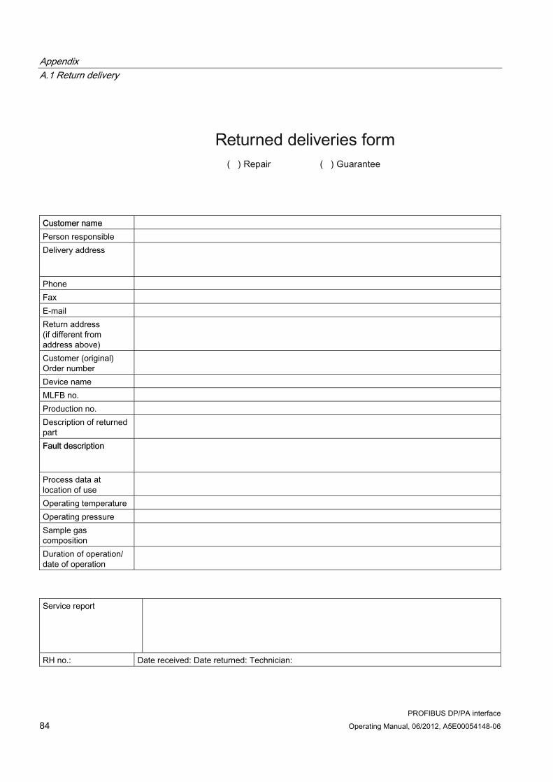
Appendix A.1 Return delivery
PROFIBUS DP/PA interface 84 Operating Manual, 06/2012, A5E00054148-06
Customer name Person responsible Delivery address
Phone Fax E-mail Return address (if different from address above)
Customer (original) Order number
Device name MLFB no. Production no. Description of returned part
Fault description
Process data at location of use
Operating temperature Operating pressure Sample gas composition
Duration of operation/ date of operation
Service report
RH no.: Date received: Date returned: Technician:

List of abbreviations
PROFIBUS DP/PA interface Operating Manual, 06/2012, A5E00054148-06 85
List of abbreviations BB.1 List of abbreviations
Abbreviation/symbol
Description
°C Degrees Celsius A Ampere AC Alternate Current Alternating current ADC Analog to Digital Converter AI Analog Input AO Analog Output C6 CALOMAT 6 C62 CALOMAT 62 cm Centimeter CTB Control Transducer Block DC Direct Current Direct current DD Device Description Device description DI Digital Input DIN Deutsche Industrie-Norm (German industrial standard) DO Digital Output DP Distributed Periphery, a PROFIBUS version DV Device Revision EEPROM Electrically erasable programmable read-only memory ELAN Emulated Local Area Network Emulated local data network EN Europäische Norm (European standard) F n Fault (with number) F6 FIDAMAT 6 G Ground GND Ground GSD Generic Station Description H2S Hydrogen sulfide HW Hardware IEC International Electrotechnical Commission IR Infrared (measured component) KB Kilobyte LCD Liquid Crystal Display, (liquid crystal display) LFB Logbook Function Block Logbook function block

List of abbreviations B.1 List of abbreviations
PROFIBUS DP/PA interface 86 Operating Manual, 06/2012, A5E00054148-06
Abbreviation/symbol
Description
LSB Least significant bit Least significant digit mA Milliampere Mbps (Megabits per second) mg/m3 Milligram per cubic meter MLFB Order number (German Maschinenlesbare FabrikateBezeichnung) mm Millimeter MSB Most significant bit Most significant bit NC Not connected (Not connected or not assigned for contacts) O2 Oxygen O6 OXYMAT 6 O61 OXYMAT 61 O64 OXYMAT 64 PA Process Automation, a PROFIBUS version PB Physical Block PC Personal Computer PCS Process Control System (Process control system) PDM Process Device Manager PI PROFIBUS International PROFIBUS Process Field Bus, a standard for fieldbus communication in automation technology RAM Random Access Memory (random access memory) SUB-D D-shaped SUB-miniature connector SW Software TB Transducer Block (transducer block) U23 ULTRAMAT 23 U6 ULTRAMAT 6 V Volt V n.n.n Version (with number) vpm (Volume parts per million W n Warning (with number) TCD Thermal Conductivity Detector


Siemens AktiengesellschaftSector IndustryIndustry AutomationSensors and Communication
76181 Karlsruhe
Subject to change without prior noticeA5E00054148-06 (order no.-version)© 2012
www.siemens.com/processautomation
A5E000540148