Ontheself-excitedvibrationsofaviscoelasticallycovered...
12
Rakenteiden Mekaniikka (Journal of Structural Mechanics) Vol. 44, No 3, 2011, pp. 231 – 242 On the self-excited vibrations of a viscoelastically covered cylinder in rolling contact using FE method Anssi T. Karttunen and Raimo von Hertzen Summary. As a result of ever-increasing speeds, the self-excited vibration of polymer-covered cylinders in rolling contact is becoming a more serious problem in many industrial processes. The vibration is generated by the viscoelastic behavior of the polymer covers. In this work, this vibration phenomenon, often referred to as barring, is studied using a two-dimensional rolling contact finite element model. The contact between two cylinders is modeled as a hard contact and the kinematic contact algorithm is used. The material parameters of the viscoelastic polymer cover of the other cylinder span a large relaxation spectrum. Readily available finite element software and tools are used for modeling and computations. The results show that strong barring vibration is a result of a resonance condition created in the rolling contact system. The vibration leads to the formation of a wave-like polygonal deformation pattern on the polymer-covered cylinder. The finite element model can provide detailed information on various phenomena, such as the nip waves, which have not been detected before by simplistic models. Key words: polymer cover, viscoelasticity, barring, vibration, nip Introduction Contact vibrations of polymer-covered rolling cylinders have an adverse effect on the quality of the end product in industrial processes such as paper calendering and pressing. The vibrations originate from the viscoelastic behavior of the covers. Let us consider a two-cylinder system with a polymer cover on the other cylinder. The cover deforms viscoelastically within the contact area of the cylinders, that is, in the nip. For the most part, the deformations on the polymer cover recover quickly outside the nip, but the residual deformation acts as a time-delayed feedback as it returns to the nip after one revolution, causing self-excited vibration in the system. The vibration can lead to the formation of a wave-like deformation pattern on the cover of the cylinder. Furthermore, the surface deformations have a tendency to accumulate, which leads to severe, unstable vibration of the rolling system during its operation. In the present paper, the aim is to investigate this vibration phenomenon, often referred to as barring. Classic papers related to contact vibrations deal with elastic bodies in rolling contact [1, 2]. The well-known methods to analyze rolling contact systems are summarized in Johnson’s book, which covers also basic aspects of contact vibrations [3]. Another in- depth treatise on contact mechanics, concentrating more on three-dimensional bodies and numerical aspects, is Kalker’s book [4]. In recent years, as the available computing power has increased, the focus has been on applying the finite and the boundary element methods in contact problems. For viscoelastic bodies rolling in contact see e.g. [5, 6, 7]. Most contact mechanical studies focus purely on the analysis of contact stresses. It is customary that the inertial effects are neglected and the vibration of the rolling bodies is 231
-
Upload
trinhkhanh -
Category
Documents
-
view
216 -
download
1
Transcript of Ontheself-excitedvibrationsofaviscoelasticallycovered...

Rakenteiden Mekaniikka (Journal of Structural Mechanics)Vol. 44, No 3, 2011, pp. 231 – 242
On the self-excited vibrations of a viscoelastically coveredcylinder in rolling contact using FE method
Anssi T. Karttunen and Raimo von Hertzen
Summary. As a result of ever-increasing speeds, the self-excited vibration of polymer-coveredcylinders in rolling contact is becoming a more serious problem in many industrial processes.The vibration is generated by the viscoelastic behavior of the polymer covers. In this work, thisvibration phenomenon, often referred to as barring, is studied using a two-dimensional rollingcontact finite element model. The contact between two cylinders is modeled as a hard contactand the kinematic contact algorithm is used. The material parameters of the viscoelastic polymercover of the other cylinder span a large relaxation spectrum. Readily available finite elementsoftware and tools are used for modeling and computations. The results show that strong barringvibration is a result of a resonance condition created in the rolling contact system. The vibrationleads to the formation of a wave-like polygonal deformation pattern on the polymer-coveredcylinder. The finite element model can provide detailed information on various phenomena,such as the nip waves, which have not been detected before by simplistic models.
Key words: polymer cover, viscoelasticity, barring, vibration, nip
Introduction
Contact vibrations of polymer-covered rolling cylinders have an adverse effect on thequality of the end product in industrial processes such as paper calendering and pressing.The vibrations originate from the viscoelastic behavior of the covers. Let us considera two-cylinder system with a polymer cover on the other cylinder. The cover deformsviscoelastically within the contact area of the cylinders, that is, in the nip. For the mostpart, the deformations on the polymer cover recover quickly outside the nip, but theresidual deformation acts as a time-delayed feedback as it returns to the nip after onerevolution, causing self-excited vibration in the system. The vibration can lead to theformation of a wave-like deformation pattern on the cover of the cylinder. Furthermore,the surface deformations have a tendency to accumulate, which leads to severe, unstablevibration of the rolling system during its operation. In the present paper, the aim is toinvestigate this vibration phenomenon, often referred to as barring.
Classic papers related to contact vibrations deal with elastic bodies in rolling contact[1, 2]. The well-known methods to analyze rolling contact systems are summarized inJohnson’s book, which covers also basic aspects of contact vibrations [3]. Another in-depth treatise on contact mechanics, concentrating more on three-dimensional bodiesand numerical aspects, is Kalker’s book [4]. In recent years, as the available computingpower has increased, the focus has been on applying the finite and the boundary elementmethods in contact problems. For viscoelastic bodies rolling in contact see e.g. [5, 6, 7].Most contact mechanical studies focus purely on the analysis of contact stresses. It iscustomary that the inertial effects are neglected and the vibration of the rolling bodies is
231

not of interest. There is a clear need for models which reach out towards inertia-relatedissues in rolling contact of viscoelastic bodies.
The self-excited vibration mechanism caused by viscoelastic cover behavior in rollingcontact is not yet fully understood. The barring vibration has been studied primarily using1D models [8, 9, 10, 11, 12, 13, 14]. Together these papers succeed in explaining importantbasic characteristics of barring. In addition, interesting experimental results related tothe problem can be found in papers by Chinn and Vuoristo et al. [15, 16, 17]. Based onthe 1D modeling approach, methods have been developed to diminish harmful vibrationsin rolling contact systems [18, 19, 20, 21]. Although the vastly studied 1D models bearnotable intelligence, from the point of view of multidimensional contact mechanics andviscoelasticity the 1D modeling approach is insufficient.
In a recent study, a step has been taken towards the right direction by using a proper2D contact mechanical approach in modeling the nip contact of two cylinders [14]. Still,to model realistic material behavior, the relaxation spectrum of the viscoelastic materialshould be taken into account to a larger extent. Ultimately, any comprehensive analyticalmodel leads to a rigorous set of equations for which it is impossible to find an analyticalsolution. Another possibility, utilized in this paper, is to approach the viscoelastic contactproblem using the finite element method and tools which are already provided by up-to-date FE softwares. In this paper, for the purpose of elucidating the self-excited vibrationmechanism, a 2D FE rolling contact model built using ABAQUS is studied.
Numerical model of a rolling contact system
General setup
The 2D two-cylinder system under investigation is shown in Fig. 1. The polymer-coveredupper cylinder is rolling in frictionless contact with the lower cylinder. The angularvelocities of the cylinders are given as time-dependent kinematic conditions. At thebeginning of the simulation the cylinders are touching at a point. The contact is createdby setting a vertical force to the center of the upper cylinder. The force increases linearlyfrom zero to a constant value in a short period of time. Simultaneously, the cylinder alsostarts to rotate from rest to a desired angular velocity.
Figure 1. Schematic representation of the studied viscoelastically covered rolling contact system.
232

Figure 2. Mesh detail of the polymer cover.
The upper cylinder is supported by a linear spring-damper system and the cylinder isallowed to translate only in vertical direction. The steel core of the cylinder is modeled asrigid and the mass of the core is m. The polymer cover on the outer rim is viscoelastic.The lower cylinder is modeled as a massless rigid surface and the support of the cylinderis also rigid. The diameters of the upper and lower cylinder are 0.42 m (with cover) and0.8 m, respectively. The thickness of the polymer cover is 7 mm. For the utilized planestrain model the width of the polymer cover in the longitudinal direction is set to 0.15m. The polymer cover is modeled using three-node constant strain triangle (CST) finiteelements1 with linear viscoelastic constitutive behavior. The model has 27160 elementsand a total of 15103 nodes, a detail of the mesh is shown in Fig. 2. The global elementsize has been set to 0.75 mm and the size on the inner edge to 1.0 mm.
Constitutive behavior of the viscoelastic polymer cover
Within the context of small strains, the constitutive equation for an isotropic viscoelasticmaterial can be written in an hereditary integral form as
σ(t) =
∫ t
0
2G(t− τ)de
dτdτ + I
∫ t
0
K(t− τ)dφ
dτdτ , (1)
where σ is the Cauchy stress tensor, G is the shear modulus, K is the bulk modulus, e isthe deviatoric part of the strain, φ is the volumetric part of the strain, t is current time,τ is past time and I is the identity tensor [22].
The moduli can be represented in terms of the Prony series. For the shear moduluswe get
G = G0
[
1−N∑
i=1
gi(1− e−t/τGi )
]
, (2)
where gi = Gi/G0 [22]. An analogous expression can be written for the bulk modulus.The deviatoric and volumetric parts are allowed to follow different relaxational behavior.The Prony representation corresponds to the solution of the classical Generalized Maxwellmodel of viscoelasticity. To perform numerical analysis, Eq. (1) needs to be integratedto the numerical solution, see [22]. The material parameters used for the polymer coverin this study are given in Table 1.
1ABAQUS/Explicit element type CPE3
233
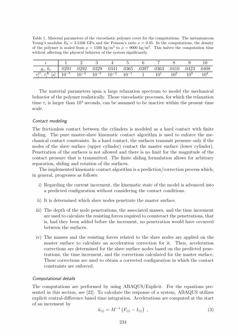
Table 1. Material parameters of the viscoelastic polymer cover for the computations. The instantaneousYoung’s modulus E0 = 3.5166 GPa and the Poisson’s ratio ν = 0.35. In the computations, the densityof the polymer is scaled from ρ = 1500 kg/m3 to ρ = 9000 kg/m3. This halves the computation timewithout affecting the physical behavior of the system significantly.
i 1 2 3 4 5 6 7 8 9 10gi, ki .0291 .0292 .0329 .0341 .0365 .0397 .0363 .0410 .0423 .0408
τGi , τKi [s] 10−5 10−4 10−3 10−2 10−1 1 101 102 103 104
The material parameters span a large relaxation spectrum to model the mechanicalbehavior of the polymer realistically. Those viscoelastic processes, for which the relaxationtime τi is larger than 104 seconds, can be assumed to be inactive within the present timescale.
Contact modeling
The frictionless contact between the cylinders is modeled as a hard contact with finitesliding. The pure master-slave kinematic contact algorithm is used to enforce the me-chanical contact constraints. In a hard contact, the surfaces transmit pressure only if thenodes of the slave surface (upper cylinder) contact the master surface (lower cylinder).Penetration of the surfaces is not allowed and there is no limit for the magnitude of thecontact pressure that is transmitted. The finite sliding formulation allows for arbitraryseparation, sliding and rotation of the surfaces.
The implemented kinematic contact algorithm is a prediction/correction process which,in general, progresses as follows:
i) Regarding the current increment, the kinematic state of the model is advanced intoa predicted configuration without considering the contact conditions.
ii) It is determined which slave nodes penetrate the master surface.
iii) The depth of the node penetrations, the associated masses, and the time incrementare used to calculate the resisting forces required to counteract the penetrations, thatis, had they been added before the increment, no penetration would have occurredbetween the surfaces.
iv) The masses and the resisting forces related to the slave nodes are applied on themaster surface to calculate an acceleration correction for it. Then, accelerationcorrections are determined for the slave surface nodes based on the predicted pene-trations, the time increment, and the corrections calculated for the master surface.These corrections are used to obtain a corrected configuration in which the contactconstraints are enforced.
Computational details
The computations are performed by using ABAQUS/Explicit. For the equations pre-sented in this section, see [22]. To calculate the response of a system, ABAQUS utilizesexplicit central-difference based time integration. Accelerations are computed at the startof an increment by
u(i) = M−1(
F(i) − I(i))
, (3)
234

where M is the diagonal element mass matrix, F is the vector of externally applied forcesand I is the vector of internal forces. Velocities and displacements are computed by
u(i+1/2) = u(i−1/2) +∆t(i+1) +∆t(i)
2u(i) (4)
u(i+1) = u(i) +∆t(i+1)u(i+1/2) . (5)
After this, the element level calculations are performed and then the next incrementalstep is taken. The method is explicit in the sense that the kinematic state is advancedusing values of u(i−1/2) and u(i) based on the previous increment.
In the explicit method, each increment is computationally inexpensive, because thereare no simultaneous equations to be solved. An estimate for the stable time increment is
∆tstable ≈Lmin
cd, (6)
where Lmin is the smallest element dimension in the mesh and the dilational wave speedis
cd =
√
λ+ 2µ
ρ, (7)
where λ and µ are Lame constants, and ρ is the density of the material. With a dense mesh,Eq. (6) typically results in very small time increments. Therefore, the explicit method isnaturally suitable for achieving high resolution solutions for high-speed transient dynamicevents, especially, if contact conditions causing extreme discontinuities are included.
For accuracy considerations, the energy balance of the model is investigated. Com-paring the energy components of the model, it can be determined whether the analysis isgiving physically reasonable results. The total energy expression used in ABAQUS, whichshould be a constant (zero), for the model is
ETOT = EE + ECD + EV + EKE − EW − EPW , (8)
where EE is the strain energy, ECD is the energy dissipated by viscoelasticity, EV is theviscous dissipated energy, EKE is the kinetic energy, EW is the work of external forcesand EPW is the work of contact penalties. Generally, there is a small error in ETOT ina numerical model. Large errors imply that the time increment is too large and causesinstability, or the mesh is not dense enough. However, note that the energy inspectiondoes not completely replace a mesh convergence study.
The studied model can be decomposed efficiently into eight domains, which allows theuse of parallel computing. The memory requirements in the explicit method are very low,due to the absence of a global stiffness matrix required in implicit methods, in particular.Numerical computations are performed using an up-to-date Windows workstation andHP CP4000 BL ProLiant supercluster at CSC. With the current model, one second ofsimulation takes about five hours. Cluster computing allows one to perform multiplesimultaneous computer runs, but does not increase the simulation speed as the modelcannot be divided efficiently into more than eight domains.
By default, ABAQUS uses artificial bulk viscosity damping to introduce some dampinginto an explicit model. However, in this study the bulk viscosity has been set to zero.Damping is included in the model via the viscoelasticity of the polymer cover and thediscrete dashpot of the upper cylinder.
235
Results
In the computations, the total mass of the upper cylinder was 572 kg and the parametervalues for the support stiffness and damping were set to k = 51.8 MN/m and c = 84Ns/m, respectively. Fig. 3 shows the vertical displacement of the upper cylinder in asimulation run. The cylinder is accelerated from rest to an angular velocity of ω = 100rad/s using a linear ramp in the time interval 0− 5 s. In the interval 5− 55 s, a smallerangular acceleration is applied and after 55 s the angular velocity ω = 146.1 rad/s (fr =ω/2π = 23.25 Hz) is held constant. After the contact has been created during the firsttwo seconds, the vertical force at the center of the upper cylinder is F = 50 kN and thevertical displacement of the upper cylinder is 70 µm. Evidently, the size of the contactarea between the cylinders has an effect on the eigenfrequency of the system. With thecreated nip compression the eigenfrequency for the vertical vibration of the upper cylinderis fn = 210 Hz.
0 10 20 30 40 50 60−80
−60
−40
−20
0
Time (s)
Dis
pla
cem
ent
(µm
)
60 60.01 60.02 60.03 60.04
−75
−70
−65
−60
One revolution period
Figure 3. Vertical displacement response of the upper cylinder. Within the time intervals 0− 5 s, 5− 55s and 55− 60.5 s, the angular accelerations α = 20 rad/s2, 0.922 rad/s2 and 0 are used, respectively.
It can be seen from Fig. 3 that there are angular velocity ranges in which the vibrationamplitude of the cylinder increases quickly, that is, strong barring appears. Fig. 4 showsa waterfall plot computed using the displacement signal from the time interval 5 − 55 s.Fig. 4 shows that there is an amplitude peak in the vicinity of f = 210 Hz correspondingto the strong barring velocity ranges, indicating that the system is in resonance. We candefine a polygonal number Ni = f/fr which gives essential information on the deformationpattern of the polymer cover. The pattern is evidently linked to the vibration frequency ofthe system – the long-term shape of the pattern is determined by the number of vibrationperiods of the upper roll in one revolution period. At t = 60 s the polygonal number isN9 = f/fr = 210/23.25 = 9. It can be seen from Fig. 4 that all the polygonal shapesseem to co-exist, however, only one is dominant at a time.
236

0 50 100 150 200 250 30010
20
30
40
50
0
1
2
3
4
5
6
x 10−7
Frequency (Hz)
Time (s)
Am
pli
tud
e (µ
m)
N1
N4
N7
Figure 4. Waterfall plot computed by FFT from the displacement signal of Fig. 3 in the time interval5 − 55 s. The amplitude peak appears at 210 Hz corresponding to the eigenfrequency of the system.Thus, the system is in barring resonance.
The energy balance of the model is investigated briefly in Fig. 5 based on the sim-ulation of Fig. 3. The relative error in ETOT stays under 0.1 % at all times, thus thenumerical analysis yields physically feasible results.
0 10 20 30 40 50 60−0.1
−0.05
0
Time (s)
ET
OT /
Eext
(%)
0 10 20 30 40 50 60−40
−20
0
ET
OT (
J)
ETOT
/ Eext
ETOT
Figure 5. Energy balance of the system based on the simulation of Fig. 3. The numerical errors aresmall, therefore, the model produces realistic results. Here Eext = EW +EPW is the total external workdone on the system (see Eq. (8)).
237

0 10 20 30 40 50 60−100
−80
−60
−40
−20
0
Time (s)
Dis
pla
cem
ent
(µm
)
Figure 6. Vertical displacement response of the upper cylinder. The angular velocity achieves the value146.1 rad/s at t = 5 s after which it remains constant. This value corresponds to the polygonal numberN9 = 9 and leads to a strong resonance.
Fig. 6 shows the displacement response of the upper cylinder as it is accelerated fromrest to an angular velocity of ω = 146.1 rad/s in five seconds and after this the angularvelocity is held as constant. In the time interval 7−17 s the vibration amplitude increasesin a linear manner, after which there is a fast exponential type increase for a short periodof time, then the amplitude continues to increase steadily at a lower pace.
0 0.2 0.4 0.6 0.8 1 1.2
−70
−60
−50
−40
−30
−20
−10
0
Upper cylinder circumference (m)
Rad
ial
dis
pla
cem
ent
of
cover
surf
ace
(µm
)
0.65 0.7 0.75 0.8
−2
0
2
Nip entry side
Figure 7. Radial displacement of the surface of the polymer cover. Nip waves are generated by a strongand sudden deformation of the cover when entering or leaving the nip.
238
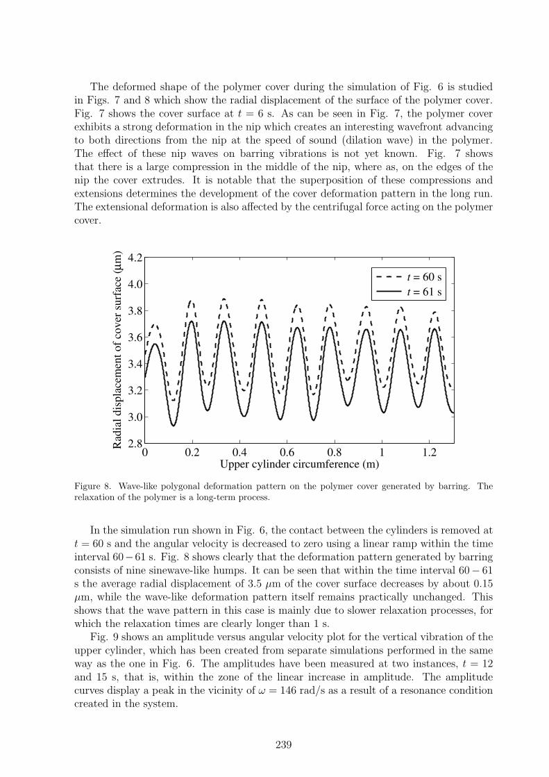
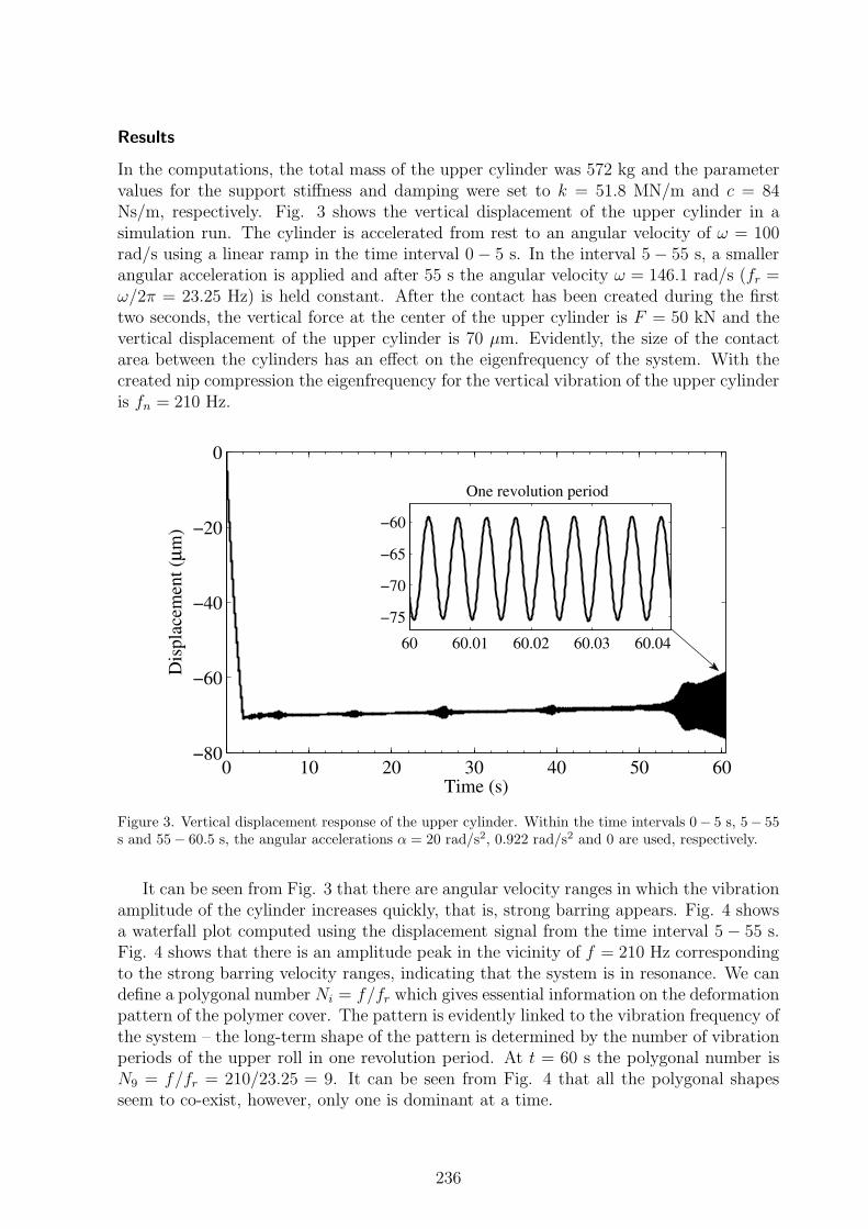
The deformed shape of the polymer cover during the simulation of Fig. 6 is studiedin Figs. 7 and 8 which show the radial displacement of the surface of the polymer cover.Fig. 7 shows the cover surface at t = 6 s. As can be seen in Fig. 7, the polymer coverexhibits a strong deformation in the nip which creates an interesting wavefront advancingto both directions from the nip at the speed of sound (dilation wave) in the polymer.The effect of these nip waves on barring vibrations is not yet known. Fig. 7 showsthat there is a large compression in the middle of the nip, where as, on the edges of thenip the cover extrudes. It is notable that the superposition of these compressions andextensions determines the development of the cover deformation pattern in the long run.The extensional deformation is also affected by the centrifugal force acting on the polymercover.
0 0.2 0.4 0.6 0.8 1 1.22.8
3.0
3.2
3.4
3.6
3.8
4.0
4.2
Upper cylinder circumference (m)
Rad
ial
dis
pla
cem
ent
of
cov
er s
urf
ace
(µm
)
t = 60 s
t = 61 s
Figure 8. Wave-like polygonal deformation pattern on the polymer cover generated by barring. Therelaxation of the polymer is a long-term process.
In the simulation run shown in Fig. 6, the contact between the cylinders is removed att = 60 s and the angular velocity is decreased to zero using a linear ramp within the timeinterval 60−61 s. Fig. 8 shows clearly that the deformation pattern generated by barringconsists of nine sinewave-like humps. It can be seen that within the time interval 60− 61s the average radial displacement of 3.5 µm of the cover surface decreases by about 0.15µm, while the wave-like deformation pattern itself remains practically unchanged. Thisshows that the wave pattern in this case is mainly due to slower relaxation processes, forwhich the relaxation times are clearly longer than 1 s.
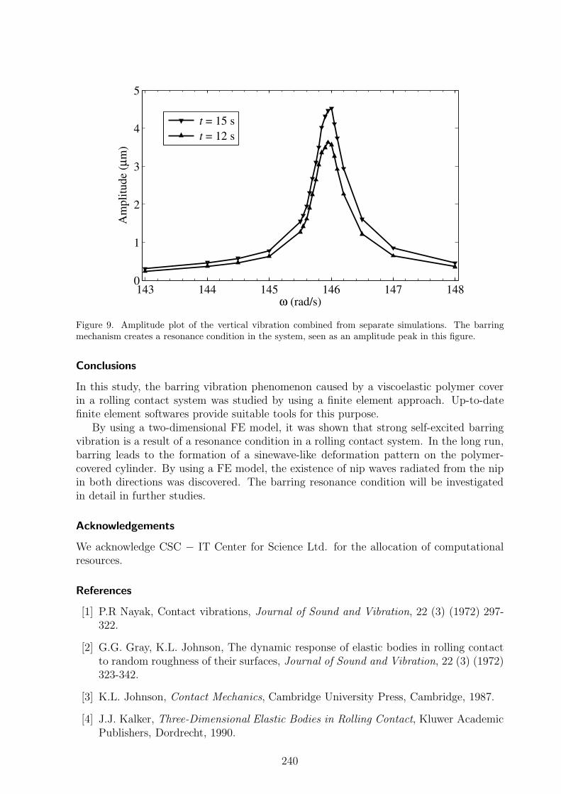
Fig. 9 shows an amplitude versus angular velocity plot for the vertical vibration of theupper cylinder, which has been created from separate simulations performed in the sameway as the one in Fig. 6. The amplitudes have been measured at two instances, t = 12and 15 s, that is, within the zone of the linear increase in amplitude. The amplitudecurves display a peak in the vicinity of ω = 146 rad/s as a result of a resonance conditioncreated in the system.
239
143 144 145 146 147 1480
1
2
3
4
5
ω (rad/s)
Am
pli
tud
e (µ
m)
t = 15 s
t = 12 s
Figure 9. Amplitude plot of the vertical vibration combined from separate simulations. The barringmechanism creates a resonance condition in the system, seen as an amplitude peak in this figure.
Conclusions
In this study, the barring vibration phenomenon caused by a viscoelastic polymer coverin a rolling contact system was studied by using a finite element approach. Up-to-datefinite element softwares provide suitable tools for this purpose.
By using a two-dimensional FE model, it was shown that strong self-excited barringvibration is a result of a resonance condition in a rolling contact system. In the long run,barring leads to the formation of a sinewave-like deformation pattern on the polymer-covered cylinder. By using a FE model, the existence of nip waves radiated from the nipin both directions was discovered. The barring resonance condition will be investigatedin detail in further studies.
Acknowledgements
We acknowledge CSC − IT Center for Science Ltd. for the allocation of computationalresources.
References
[1] P.R Nayak, Contact vibrations, Journal of Sound and Vibration, 22 (3) (1972) 297-322.
[2] G.G. Gray, K.L. Johnson, The dynamic response of elastic bodies in rolling contactto random roughness of their surfaces, Journal of Sound and Vibration, 22 (3) (1972)323-342.
[3] K.L. Johnson, Contact Mechanics, Cambridge University Press, Cambridge, 1987.
[4] J.J. Kalker, Three-Dimensional Elastic Bodies in Rolling Contact, Kluwer AcademicPublishers, Dordrecht, 1990.
240

[5] L. Nasdala, M. Kaliske, A. Becker, H. Rothert, An efficient viscoelastic formulationfor steady-state rolling structures, Computational Mechanics, 22 (5) (1998) 395-403.
[6] J.A. Gonzalez, R. Abascal, Efficient stress evaluation of stationary viscoelastic rollingcontact problems using boundary element method: Application to viscoelastic coat-ings, Engineering Analysis with Boundary Elements. 30 (6) (2006) 426-434.
[7] M. Ziefle, U. Nackenhorst, Numerical techniques for rolling rubber wheels: treatmentof inelastic material properties and frictional contact, Computational Mechanics, 42(3) (2008) 337-356.
[8] A.T. Karttunen, R. von Hertzen, Polymer cover induced self-excited vibrations ofnipped rolls, Journal of Sound and Vibration, 330 (16) (2011) 3959-3972.
[9] A. Sueoka, T. Ryu, T. Kondou, Y. Tsuda, K. Katayama, K. Takasaki, M. Yamaguchi,H. Hirooka, Polygonal deformation of roll-covering rubber, JSME International Jour-
nal, Series C, 39 (1) (1996) 1-10.
[10] A. Sueoka, T. Ryu, M. Yoshikawa, T. Kondou, Y. Tsuda, Pattern formation gener-ated in a winder system of textile machine, JSME International Journal, Series C,41 (3) (1998) 630-638.
[11] M. Jorkama, R. von Hertzen, Delay phenomena in roll vibrations, Proceedings of theVIII Finnish Mechanics Days, June 2003, Espoo, Finland, pp. 111-121.
[12] M. Jorkama, R. von Hertzen, Two-drum winder stability analysis, Pulp & Paper
Canada, 108 (5) (2007) 35-37.
[13] L.H. Yuan, Analysis of delay phenomena in roll dynamics, Doctoral Thesis, TampereUniversity of Technology, 2002.
[14] L.H. Yuan, V.-M. Jarvenpaa, Nonlinear vibrations in a covered roll system with vis-coelastic contact, Communications in Nonlinear Science and Numerical Simulation,14 (7) (2009) 3170-3178.
[15] F. Chinn, Dynamic instability of poly covered press rolls, Pulp & Paper Canada, 100(1) (1999) 11-14.
[16] T. Vuoristo, V.-T. Kuokkala, E. Keskinen, Dynamic compression testing of particle-reinforced polymer roll cover materials, Composites: Part A, 31 (8) (2000) 815-822.
[17] T. Vuoristo, V.-T. Kuokkala, Creep, recovery and high strain rate response of softroll cover materials, Mechanics of Materials, 34 (8) (2002) 493-504.
[18] N. Sowa, T. Kondou, H. Mori, M.S. Choi, Method of preventing unstable vibra-tion caused by time delays in contact rotating systems (application of new stabilityanalysis), JSME International Journal, Series C, 49 (4) (2006) 973-982.
[19] K. Matzusaki, A. Sueoka, T. Ryu, H. Morita, Generation mechanism of polygonalwear of work rolls in a hot leveler and a countermeasure by dynamic absorbers,International Journal of Machine Tools and Manufacture, 48 (9) (2008) 983-993.
241

[20] K. Matzusaki, A. Sueoka, T. Ryu, H. Morita, K. Hidaka, S. Noguchi, Polygonal wearof work rolls in a hot leveler of a steel making machine (4th Report, Experimental ver-ification of a countermeasure by using dynamic absorbers), Journal of Environment
and Engineering, 3 (1) (2008) 146-157.
[21] T. Ryu, K. Matzusaki, A. Sueoka, H. Morita, Countermeasures against pattern for-mation phenomena of thin sheet winder by using dynamic absorbers, Journal of
System Design and Dynamics, 3 (5) (2009) 814-826.
[22] Dassault Systemes Simulia Corp., Abaqus 6.10 Theory Manual, 2010, Providence,RI.
Anssi T. Karttunen, Raimo von HertzenAalto University School of Engineering, Department of Applied MechanicsP.O. Box 14300, FI-00076 Aalto, [email protected], [email protected]
242