Ontario, California 91761 Instructions...
23
Ontario, California 91761 Instructions Manual MODEL NO: 60000LP 4 Burner Stainless Steel, Lights, Built-In, L.P. (Propane) Gas MODEL NO: 60000NG 4 Burner Stainless Steel, Lights, Built-In, Natural Gas MODEL NO: 75000LP 4 Burner Stainless Steel, Rotisserie, Lights, Built-In, L.P. (Propane) Gas MODEL NO: 75000NG 4 Burner Stainless Steel, Rotisserie, Lights, Built-In, Natural Gas MODEL NO: 90000LP 5 Burner Stainless Steel, Rotisserie, Lights, Built-In, L.P. (Propane) Gas MODEL NO: 90000NG 5 Burner Stainless Steel, Rotisserie, Lights, Built-In, Natural Gas TABLE OF CONTENTS PAGE SAFETY INSTRUCTIONS ………………………………………………………………………………..……………… 2 INSTALLATION INSTRUCTIONS ………………………………………………………………………….………..….. 6 LIGHTING & OPERATING INSTRUCTIONS ……………………………………………………………………....…… 11 CLEANING & MAINTENANCE …………………………...………………………………………………………..….…. 14 TROUBLESHOOTING …………………………………………………………………………………………………….. 15 PARTS LIST ……………………………………………..………………………………………………………….……… 16 WARRANTY.……………………………………………..…………………………………………………………..……... 23 READ THE FOLLOWING INSTRUCTIONS CAREFULLY AND BE SURE YOUR GRILL IS PROPERLY INSTALLED, ASSEMBLED AND CARED FOR. FAILURE TO FOLLOW THESE INSTRUCTIONS MAY RESULT IN SERIOUS BODILY INJURY AND/OR PROPERTY DAMAGE. IF YOU HAVE QUESTIONS CONCERNING ASSEMBLY OR OPERATION, CONSULT YOUR DEALER, GAS APPLIANCE SERVICE REPRESENTATIVE OR YOUR GAS COMPANY NOTE TO INSTALLER: LEAVE THESE INSTRUCTIONS WITH THE CONSUMER AFTER INSTALLATION. NOTE TO THE CONSUMER RETAIN THESE INSTRUCTIONS FOR FUTURE REFERENCE. THIS OUTDOOR COOKING GAS APPLIANCE IS NOT INTENDED TO BE INSTALLED IN OR ON RECREATIONAL VEHICLES AND/OR BOATS. 1 Certificate 252521-2405769 Project 2405769 Figure No.(75)
Transcript of Ontario, California 91761 Instructions...

Ontario, California 91761
Instructions Manual
MODEL NO: 60000LP
4 Burner Stainless Steel, Lights, Built-In, L.P. (Propane) Gas
MODEL NO: 60000NG
4 Burner Stainless Steel, Lights, Built-In, Natural Gas
MODEL NO: 75000LP
4 Burner Stainless Steel, Rotisserie, Lights, Built-In, L.P. (Propane) Gas
MODEL NO: 75000NG
4 Burner Stainless Steel, Rotisserie, Lights, Built-In, Natural Gas
MODEL NO: 90000LP
5 Burner Stainless Steel, Rotisserie, Lights, Built-In, L.P. (Propane) Gas
MODEL NO: 90000NG
5 Burner Stainless Steel, Rotisserie, Lights, Built-In, Natural Gas
TABLE OF CONTENTS PAGE
SAFETY INSTRUCTIONS ………………………………………………………………………………..……………… 2
INSTALLATION INSTRUCTIONS ………………………………………………………………………….………..….. 6
LIGHTING & OPERATING INSTRUCTIONS ……………………………………………………………………....…… 11 CLEANING & MAINTENANCE …………………………...………………………………………………………..….…. 14 TROUBLESHOOTING …………………………………………………………………………………………………….. 15 PARTS LIST ……………………………………………..………………………………………………………….……… 16 WARRANTY.……………………………………………..…………………………………………………………..……... 23
READ THE FOLLOWING INSTRUCTIONS CAREFULLY AND BE SURE YOUR GRILL IS PROPERLY INSTALLED, ASSEMBLED AND CARED FOR. FAILURE TO FOLLOW THESE INSTRUCTIONS MAY RESULT IN SERIOUS BODILY INJURY AND/OR PROPERTY DAMAGE. IF YOU HAVE QUESTIONS CONCERNING ASSEMBLY OR OPERATION, CONSULT YOUR DEALER, GAS APPLIANCE SERVICE REPRESENTATIVE OR YOUR GAS COMPANY NOTE TO INSTALLER: LEAVE THESE INSTRUCTIONS WITH THE CONSUMER AFTER INSTALLATION. NOTE TO THE CONSUMER RETAIN THESE INSTRUCTIONS FOR FUTURE REFERENCE.
THIS OUTDOOR COOKING GAS APPLIANCE IS NOT INTENDED TO BE INSTALLED IN OR ON RECREATIONAL VEHICLES AND/OR BOATS.
1 Certificate 252521-2405769 Project 2405769 Figure No.(75)
SAFETY INSTRUCTIONS
Read carefully before assembling and operating your gas grill This gas grill must be installed in accordance with local codes or, if in an area without local codes, with the latest edition of the National Fuel Gas Code ANSI Z223.1/NFPA54, Natural Gas and Propane Installation Code, CSA B149.1 or Propane Storage and Handling Code, B149.2.
WARNING: Fuels used in gas or oil-fired appliances and the products of combustion of such fuels, contain chemicals known to the State of California to cause cancer, birth defects and/or reproductive harm. This warning is issued pursuant to California Health & Safety Code Sec. 25249.6. THE LOCATION FOR YOUR GRILL Your gas grill is to be used OUTDOORS ONLY, with at least 21” from the back and side of any combustible surface. The grill should not be placed under or on top of any surface that will burn. Do not obstruct the flow of combustion and ventilation air around the grill housing.
PROTECT CHILDREN: keep them away from grill during use and until grill has cooled after you are finished. Do not allow children to operate grill.
Keep the fuel hose any electrical cord away from hot surfaces. Protect fuel hose from dripping grease. Avoid unnecessary twisting of hose. Visually inspect hose prior to each use for cuts, cracks excessive wear or other damage. Replace hose, if necessary. NEVER test for gas leaks with a lighted match or open flame. NEVER light grill with lid closed or before checking to insure burner tubes are fully seated aver gas valve orifices.
NEVER lean over cooking surface while lighting grill. Use barbecue tools with wood handles and good quality insulated oven mitts when operating grill.
CHECKING FOR GAS LEAKS
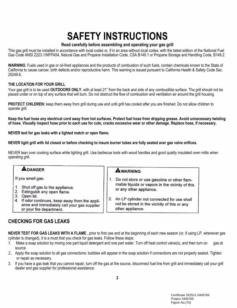
NEVER TEST FOR GAS LEAKS WITH A FLAME...prior to first use and at the beginning of each new season (or, if using LP, whenever gas cylinder is changed), it is a must that you check for gas leaks. Follow these steps: 1. Make a soap solution by mixing one part liquid detergent and one part water. Turn off heat control valve(s), and then turn on gas at
source. 2. Apply the soap solution to all gas connections: bubbles will appear in the soap solution if connections are not properly sealed. Tighten
or repair as necessary. 3. If you have a gas leak that you cannot repair, turn off the gas at the source, disconnect fuel line from grill and immediately call your grill
dealer and gas supplier for professional assistance.
2 Certificate 252521-2405769 Project 2405769 Figure No.(75)
If an external electrical source is utilized, a statement that the outdoor cooking gas appliance, when installed, must
be electrically grounded in accordance with local codes or, in the absence of local codes, with the National
Electrical Code, ANSI/NFPA 70, or the Canadian Electrical Code, CSA C22 1 This outdoor cooking gas appliance shall be used only outdoors and shall not be used in a building, garage or any
other enclosed area A serial number and model number located on this appliance should be provided for services. This outdoor cooking gas appliance is to be used with at least 21” from the back and sides of any combustible
surface. The grill should not be placed under or on top of any surface that will burn. Do not obstruct the flow
of combustion and ventilation air around the grill housing. a. Instructions for electrical equipment, separately approved by a nationally recognized testing agency that is
required to be provided with instructions for use shall be included with the instructions required with an
outdoor cooking gas appliance. This can be in its original form of duplicated within the instructions provided
with the outdoor cooking gas appliance. b. Electrical equipment provided with the outdoor cooking gas appliance shall have the following in the
instructions:
1 To protect against electric shock, do not immerse cord or plugs in water or other liquid 2 Unplug from the outlet when not in use and before cleaning. Allow to cool before putting on or taking off
parts; Constructed and marked in accordance with the Specifications for LP-Gas Cylinders of the U.S. Department of
Transportation (D.O.T.) or the National Standard of Canada, CAN/CSA-B339, Cylinders, Spheres and Tubes for
Transportation of Dangerous Goods; and Commission, as applicable; and provided with a listed overfilling
prevention device, provided with a cylinder connection device compatible with the connection for outdoor
cooking appliances Instructions, including illustrations, on the proper cylinder orientation to provide vapor
withdraw. The cylinder used must include a collar to protect the cylinder valve (a) Do not store a spare LP-gas cylinder under or near this appliance;
(b) Never fill the cylinder beyond 80 percent full;
(c) If the information in “-b12(a)” and “-b12(b)” is not followed exactly, a fire causing death or serious
injury may occur This appliance designed to use a CGA 791 Connection: “Place dust cap on cylinder valve outlet whenever the
cylinder is not in use. Only install the type of dust cap on the cylinder valve outlet that is provided with the
cylinder valve. Other types of caps or plugs may result in leakage of propane.” Proper selection of non-combustible or combustible materials for the built-in enclosure, as applicable This appliance is only for installation in a built-in enclosure constructed of non-combustible materials. (a) Keeping outdoor cooking gas appliance area clear and free from combustible materials, gasoline and
other flammable vapors and liquids
(b) Not obstructing the flow of combustion and ventilation air
(c) Keeping the ventilation opening(s) of the cylinder enclosure free and clear from debris
(d) Visually checking burner flames including pilot burner flame if provided, with pictorial representations.
3
Certificate 252521-2405769 Project 2405769 Figure No.(75)
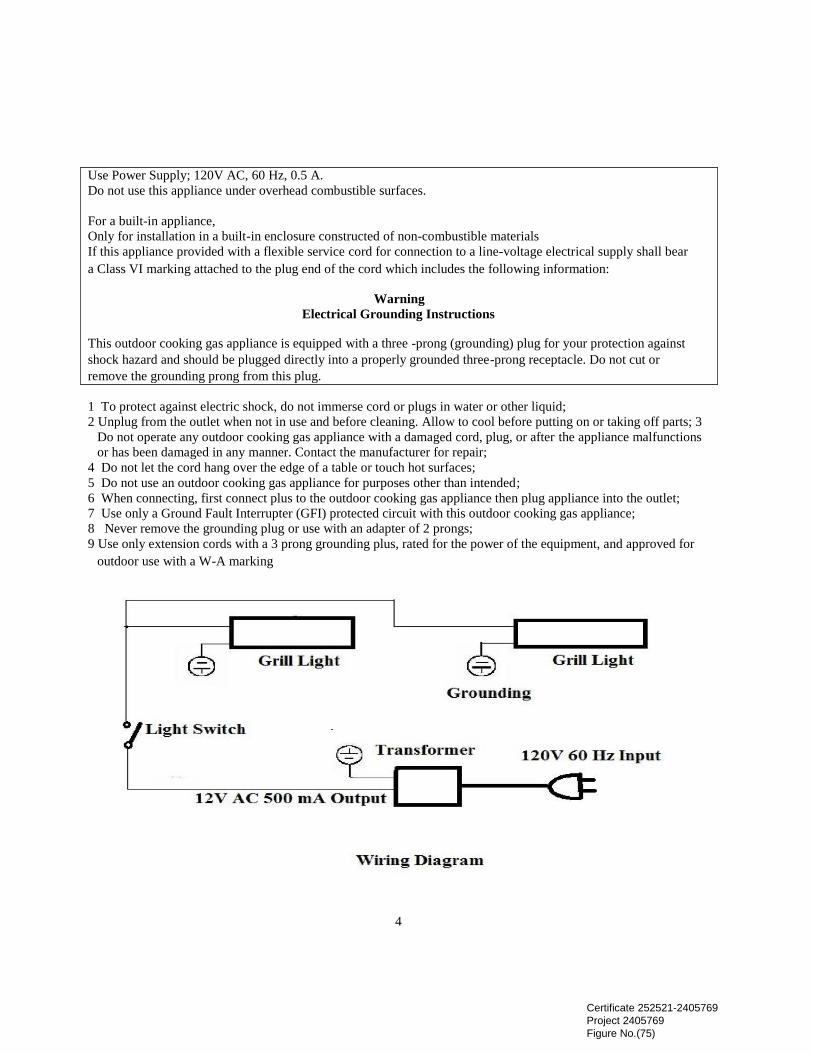
Use Power Supply; 120V AC, 60 Hz, 0.5 A. Do not use this appliance under overhead combustible surfaces. For a built-in appliance, Only for installation in a built-in enclosure constructed of non-combustible materials If this appliance provided with a flexible service cord for connection to a line-voltage electrical supply shall bear
a Class VI marking attached to the plug end of the cord which includes the following information:
Warning Electrical Grounding Instructions
This outdoor cooking gas appliance is equipped with a three -prong (grounding) plug for your protection against
shock hazard and should be plugged directly into a properly grounded three-prong receptacle. Do not cut or
remove the grounding prong from this plug. 1 To protect against electric shock, do not immerse cord or plugs in water or other liquid; 2 Unplug from the outlet when not in use and before cleaning. Allow to cool before putting on or taking off parts; 3
Do not operate any outdoor cooking gas appliance with a damaged cord, plug, or after the appliance malfunctions
or has been damaged in any manner. Contact the manufacturer for repair; 4 Do not let the cord hang over the edge of a table or touch hot surfaces; 5 Do not use an outdoor cooking gas appliance for purposes other than intended; 6 When connecting, first connect plus to the outdoor cooking gas appliance then plug appliance into the outlet;
7 Use only a Ground Fault Interrupter (GFI) protected circuit with this outdoor cooking gas appliance; 8 Never remove the grounding plug or use with an adapter of 2 prongs; 9 Use only extension cords with a 3 prong grounding plus, rated for the power of the equipment, and approved for
outdoor use with a W-A marking
4
Certificate 252521-2405769 Project 2405769 Figure No.(75)
NATURAL GAS SAFETY Your Natural Gas grill is designed to operate on natural gas ONLY, at a pressure of 4” water column (W.C.) regulated at the natural gas regulator attached at the back of the grill. Check with your gas utility for local gas pressure and with your local municipality for building code requirements. Check with your gas utility or with local building codes for instructions to install gas supply line, or call a licensed and knowledgeable installer. It is recommended that an ON-OFF” shutoff valve be installed at the gas supply source: - Outdoors after gas line piping exits outside wall and before quick-disconnect or before gas line piping enters ground.
- Indoors in the branch fuel line in an accessible location near the supply line.
Pipe sealing compound or pipe thread tape of the type resistant to the action of natural gas must be used on all male pipe thread. Apply compound or tape to at least the first three threads when making the connection.
This appliance and its individual shutoff valve must be disconnected from the gas supply piping system during any pressure testing of that system at pressures in excess of 1/2 psig (3.5 kPa). This appliance must be isolated from the gas supply piping system by closing its individual manual shutoff valve during any pressure testing of the gas supply piping system at test pressures equal to or less than ½ psi (3.5kpa) Turn off your gas grill when the gas supply is being tested at low pressures. This appliance must be isolated from the gas supply piping system by closing its individual valve.
WARNING: Gas valves are preset at the factory to operate on LP or natural gas. If you wish to convert, be sure to contact your grill dealer FIRST!
PROPANE GAS SAFETY Your Propane gas grill is designed to operate on propane gas ONLY, at a pressure regulated at 11” water column (W.C.) when equipped with the correct propane orifices on the valves and a propane regulator on the supply line regulated at the residential meter. Your propane gas grill is designed to be used with a standard 20 lbs gas cylinder and must be constructed and marked in accordance with specifications of the US Department of Transportation for Propane gas cylinders. Always keep cylinder securely fastened in an upright position. Never connect an unregulated propane gas cylinder to the grill. Do not subject Propane cylinders to excessive heat. CAUTION: Never store a Propane gas cylinder inside a building or in the vicinity of any gas-burning appliance. WARNING: Gas valves are preset at the factory to operate on LP or Natural Gas. If you wish to convert, be sure to contact your grill dealer FIRST!
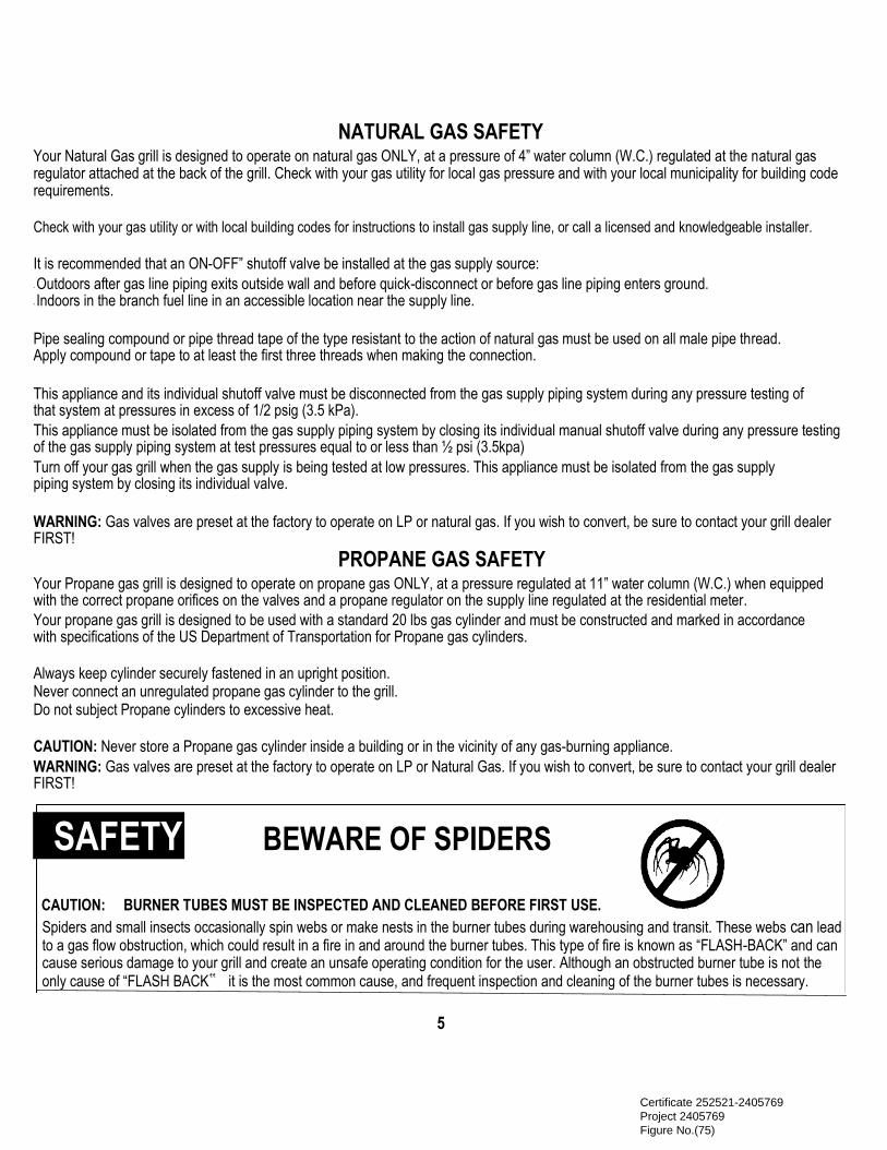
SAFETY ! BEWARE OF SPIDERS
CAUTION: BURNER TUBES MUST BE INSPECTED AND CLEANED BEFORE FIRST USE. Spiders and small insects occasionally spin webs or make nests in the burner tubes during warehousing and transit. These webs can lead to a gas flow obstruction, which could result in a fire in and around the burner tubes. This type of fire is known as “FLASH-BACK” and can cause serious damage to your grill and create an unsafe operating condition for the user. Although an obstructed burner tube is not the only cause of “FLASH BACK‟ it is the most common cause, and frequent inspection and cleaning of the burner tubes is necessary.
5 Certificate 252521-2405769 Project 2405769 Figure No.(75)
INSTALLATION INSTRUCTIONS
PLEASE READ THESE INSTRUCTIONS BEFORE INSTALLING YOUR GAS GRILL
Your Gas BBQ Grill comes to you fully assembled. We strongly recommend professional installation and hookup of the Gas BBQ grill. These instructions will provide you with the measurements necessary for you or your builder to construct a masonry structure to house your outdoor gas grill.
NOTE TO INSTALLER: Leave these instructions with the consumer for future reference. Your grill must be installed in accordance with all local building codes. SPECIFICATIONS FOR BARBECUE STRUCTURE
1. Masonry of your choice can be used for cabinet construction for the built-in gas grill. It must be non- combustible material. Keep in
mind when choosing a location for your grill that it should NOT be located under any overhead combustible construction. Upper and ground level vents must be provided for combustion air on both sides of built-in cabinet. Vents on BBQ firebox must remain unobstructed to allow for combustion air.
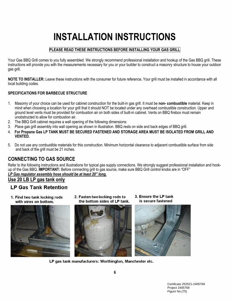
2. The BBQ Grill cabinet requires a wall opening of the following dimensions: 3. Place gas grill assembly into wall opening as shown in illustration. BBQ rests on side and back edges of BBQ grill. 4. For Propane Gas LP TANK MUST BE SECURED FASTENED AND STORAGE AREA MUST BE ISOLATED FROM GRILL AND
VENTED. 5. Do not use any combustible materials for this construction. Minimum horizontal clearance to adjacent combustible surface from side and back of the grill must be 21 inches.
CONNECTING TO GAS SOURCE Refer to the following instructions and illustrations for typical gas supply connections. We strongly suggest professional installation and hook-up of the Gas BBQ. IMPORTANT: Before connecting grill to gas source, make sure BBQ Grill control knobs are in “OFF” LP Gas regulator assembly hose should be at least 20” long.
Use 20 LB LP gas tank only
6 Certificate 252521-2405769 Project 2405769 Figure No.(75)

NATURAL GAS CONNECTIONS Pipe sealing compound or pipe thread tape of the type resistant to the action of natural gas must be used on all male pipe thread. Apply compound or tape to at least the first three threads when making the connection. Remove plastic cap from regulator installed on grill. Attach outdoor flex line ½ ” for main burner supply or 3/8” for side burner to the regulator. Attached the other end of flex line to shut-off valve thru a nipple. Attach a shut-off valve to gas supply pipe. PERFORM GAS LEAK CHECK -SEE PAGE 2
PROPANE GAS CONNECTIONS The LP gas pressure regulator and hose assembly supplied with this unit must be used without alteration. If this assembly needs to be replaced, use only the type 1 specified in the parts list supplied with this unit. Use a LP tank with a type 1 cylinder valve. Make sure the tank is firmly secured in an upright position. Turn the black coupling nut of the hose and regulator assembly in a clockwise direction. Make sure it is completely threaded onto the cylinder valve before turning gas supply on. PERFORM GAS LEAK CHECK — SEE PAGE 2 LP Gas regulator assembly hose should be At least 20” long.
7
Certificate 252521-2405769 Project 2405769 Figure No.(75)
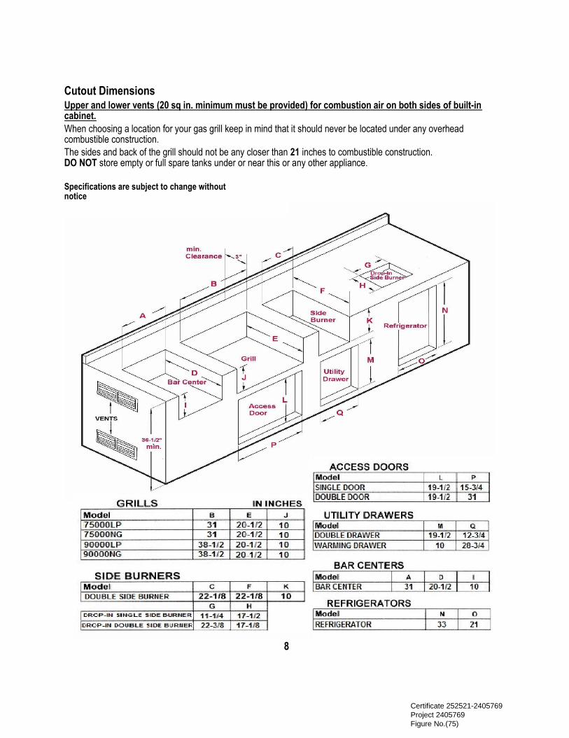
Cutout Dimensions Upper and lower vents (20 sq in. minimum must be provided) for combustion air on both sides of built-in cabinet. When choosing a location for your gas grill keep in mind that it should never be located under any overhead combustible construction. The sides and back of the grill should not be any closer than 21 inches to combustible construction. DO NOT store empty or full spare tanks under or near this or any other appliance.
Specifications are subject to change without notice
8
Certificate 252521-2405769 Project 2405769 Figure No.(75)

INSPECTING I CLEANING BURNERS AND GAS VALVE ORIFICES By following these cleaning procedures on a timely basis, your grill will be kept clean and working properly with minimum effort. BURNER CLEANING
1. Remove burner from the grill bowl. Bend a stiff wire (a light-weight coat hanger works well) into a small hook. Run the hook through
each burner tube and burner several times. 2. Use a narrow bottlebrush with a flexible handle. Run the hook through each burner tube and burner several times. 3. Wire brush entire outside surface of burner to remove loose corrosion. 4. Clean any clogged hole with a stiff wire (such as an open paper clip). 5. Inspect the burner assembly for any opening caused by correction. 6. Replace burner and put cotter pin back to hole of the cast peg beneath the burner.
7. Check the burner for proper location after replacing. To assure the valve orifices are inside of the burner tubes. See right drawing.
If the valve orifices do not fit inside the burner tubes, lighting the burners may cause explosion and/or fire. IGNITOR I ELECTRODE CHECK
With all control knobs set to OFF”, check each igniter individually for presence of spark at electrode. In turn, push each control knob in fully and turn slowly about a 1/4 turn to the left (counter-clockwise) until a click is heard; the trigger hitting the strike block should produce a blue spark at the electrode tip. Return control knob to “OFF” before checking next igniter. BURNER OPERATION CHECK 1. With BBQ Grill control knobs in “OFF” position turn on the Gas supply.
2. Light any burner by pushing its control knob in fully and slowly (3 to 4 seconds) turning it about 1/4 turn to the left (counter-clockwise)
until a click is heard. The 3 to 4 second duration should provide enough gas to light the burner. If the burner does not light, immediately return the control knob to “OFF”, wait several minutes for the gas to disperse, and repeat the process. After burner lights successfully, turn control knob to “OFF”.
NOTE: Upon first assembly the gas lines and burners will be full of air. In order for the burners to light properly the lines must fill with gas.
It may require several attempts at lighting the burners before you are successful. 3. Repeat process for each control knob/igniter, in turn, ensuring that other knobs are in “OFF” position as you perform each check.
4. If any burners fail to light after several attempts, discontinue gas supply at source and re-inspect for obstructions to gas flow and
orifices. .
9
Certificate 252521-2405769 Project 2405769 Figure No.(75)

COOKING COMPONENT INSTALLATION
IMPORTANT: Before first use wash flame tamers, cooking grids, and warming rack with warm, soapy water. Rinse and dry thoroughly. Season metal surfaces with cooking oil occasionally. (After cooking is completed, turn grill to high setting for NO MORE THAN five minutes to burn off excess grease or food residue) CAUTION: DO NOT LEAVE GRILL UNATTENDED. 1. Place stainless steel heat shields on lowest ledge under / between burners in grill bowl. 2. Place stainless steel flame tamers on lower ledge above burners in grill bowl. 2. Place cooking grids in grill bowl on ledge above flame tamers. NOW YOUR GAS GRILL IS READY TO USE. Before first use and at the beginning of each barbecue season: 1. Please read Safety, Lighting and Operating Instructions carefully. 2. Check gas valve orifices, burner tubes and burner ports for any obstructions 3. PERFORM GAS LEAK CHECK -SEE PAGE 2. Check the burner for proper location after replacing. To assure the valve orifices are inside of the burner tubes. See right drawing. If the valve orifices do not fit inside the burner tubes, lighting the burners may cause explosion and/or fire.
Grill island back venting cut out
10
Certificate 252521-2405769 Project 2405769 Figure No.(75)
LIGHTING & OPERATING INSTRUCTIONS
LIGHTING PROCEDURES Lighting Main Burner(s): 1. Become familiar with safety guidelines at front of manual. DO NOT SMOKE WHILE LIGHTING GRILL OR
CHECKING GAS SUPPLY CONNECTIONSI 2. If your grill fuel source is a LP gas cylinder, check to see that cylinder is filled. 3. Check the end of each burner tube is properly located over each valve orifice. 4. Make sure all gas connections are securely tightened. TEST FOR LEAKS WITH A SOAP SOLUTION, NEVER WITH A
FLAME. (Gas Leak Check instructions are on page 2). 5. Always open lid before lighting. 6. Set ALL BBQ Grill control knobs to OFF” and open gas supply, LP cylinder or Natural Gas Valve. 7. Ignite only the burners you intend to use, using the same method for each: Push in control knob fully and rotate
slowly (3 to 4 seconds) about 1/4 turn to the left (counter clockwise) until a click is heard. The 3 to 4 second duration should provide enough gas to light the burner. If the burner does not light, immediately return the control knob to „OFF‟ , wait several minutes for the gas to disperse, and repeat the process. After burner ignites,
repeat procedure with any other burner needed. 8. Adjust control knob(s) to desired cooking temperature. NOTE: If for some reason, igniters fail to produce a spark at the electrode tip, burners can be lit with a match.
NOTE: To light gas grill with a match, follow steps 1 through 6 above. Remove cooking grid and flame tamer from burner you wish to light. Insert lighted fireplace-type match or long-necked butane lighter placing flame near to burner ports. Press in control knob and rotate left to “HI” setting to release gas. Burner should light immediately. If more than one burner is needed, repeat procedure with each burner. Replace flame tamer and cooking grid. Turn off burners not needed, and adjust other burners to desired cooking temperature. Lighting Rotisserie Burner (if equipped): The rear infrared rotisserie burner allows for slow rotisserie cooking of meats and poultry. Infrared burners radiate heat onto the outer surface of the food. This allows cooking without the grease drippings burning on the flame tamers. To light Rotisserie Burner, 1. Always open lid before lighting. 2. Set ALL BBQ Grill control knobs to OFF” and open gas supply, LP cylinder or Natural Gas Valve. 3. The Control knob is located at the middle of the Control Panel. Push in control knob fully and rotate slowly (3 to 4 seconds) about 1/4
turn to the left (counter clockwise) until a click is heard. The 3 to 4 second duration should provide enough gas to light the burner. If the burner does not light, immediately return the control knob to „OFF‟ , wait several minutes for any accumulated gas to clear out of the grill. Keep lid closed and operate burner at the “ON” position when roistering.
WARNING: Never operate Rotisserie Burner with main (other) burner(s) ON Warming Rack must be removed when Rotisserie Burner is ON
Do not attempt to regulate the rotisserie burner by using the control knob. This control has a fixed setting and is not adjustable. NOTE: Initially, the Ceramic Panel will have a blue flame that, after some time, will change to an orange flame and the Ceramic Panel will glow an orange color. This may not be evident in bright daylight. To light Rotisserie Burner with a match, Follow steps 1 through 2 above. Insert lighted fireplace-type match or long-necked butane lighter placing flame near to the Ceramic Panel. Press in control knob and rotate left (counter clockwise) to “HI” or “ON” setting to release gas. Burner should light immediately.
11
Certificate 252521-2405769 Project 2405769 Figure No.(75)

LIGHTING & OPERATING INSTRUCTIONS
OPERATING PROCEDURE
Burn-off: Before cooking on your gas grill for the first time, burn the grill to get rid it of any odors or foreign matter by igniting the burners, closing the lid, and operating at “HI” setting for about five minutes. You may then either set the controls to “OFF” or cook on your grill immediately by turning the control knobs to a lower setting. CAUTION: DO NOT LEAVE GRILL UNATTENDED.
Preheating: It is necessary to preheat the grill for a short time before cooking certain foods, depending on the type of food and the cooking temperature. Food that requires a high cooking temperature needs preheat for five minutes; food that requires a lower cooking temperature needs only a period of two to three minutes. There is no need to preheat for casseroles or other foods that require slow cooking. COOKING TEMPERATURES
HIGH Setting - Use this setting only for fast warm-up, for searing steaks and chops, and for burning food residue from the cooking grids after the cookout is over. MEDIUM SETTING - Use this setting for most grilling, roasting or baking, and for cooking hamburgers and vegetables. LOW SETTING - Use this setting for all smoke cooking, rotisserie cooking, and when cooking very lean cuts such as fish. These temperatures vary with the outside temperature and the amount of wind.
Cooking With Indirect Heat: You can cook poultry and large cuts of meat slowly to perfection on one side of the grill by indirect heat from the next burner. The heat from the lighted burner circulates gently throughout the grill, cooking the meat or poultry without any direct flame touching it. This method greatly reduces flare-ups when cooking extra fatty cuts, because there is no direct flame to ignite the fats and juices that drip down during cooking. Place a drip pan slightly smaller than the cut of meat on the cooking grids or flame tamer surface under the meat being cooked. This will allow you to catch meat juices for making gravy.
Flare-Ups: The fats and juices that drip from the meat cause flare-ups. Since flare-ups impart the distinctive taste and color for
food cooked over an open flame, they should be expected and encouraged within reason. Nevertheless, uncontrolled flaring
can result in a ruined meal. To control excessive flare- ups caused by too high a heat setting, turn the heat control knob to a
lower setting.
CAUTION: If burners go out during operation, close gas supply at source, and turn all gas valves off. Open lid and wait five minutes before attempting to re-light (this allows accumulated gas fumes to clear). CAUTION: Should a grease fire occur, close gas supply at source, turn off all burners and leave lid closed until fire is out. CAUTION: Do not attempt to disconnect any gas fitting while your barbecue is in operation.
12
Certificate 252521-2405769 Project 2405769 Figure No.(75)

LIGHTING & OPERATING INSTRUCTIONS
ROTISSERIE COOKING
Rotisserie is mostly used to cook large pieces of meat and poultry to assure slow, even cooking. The constant turning provides a self-basting action, making food cooked on a rotisserie exceptionally moist and juicy. Rotisserie cooking generally requires 1 ½ to 4½ hrs to cook depending on the size and type of meat being cooked. You can have rotisserie cooking with indirect heat as shown or with infrared rotisserie burner.
For successful roistering, the meat should be centered and balanced as evenly as possible on the spit rod to avoid overworking the rotisserie motor.
Since indirect heat is often used in cooking on a rotisserie, a foil or aluminum drip pan is advisable to prevent excessive flare-ups. Generally, the cooking grills are removed to allow for the swing of the rotisserie. A basting pan is placed under the rotisserie area on top of the flame tamer(s) to catch the drippings.
WARNING: Never operate Rotisserie Burner with main (other) burner(s) “ON”.
Match holder with chain Insert match for manual lighting Normal Burner Flames
13 Certificate 252521-2405769 Project 2405769 Figure No.(75)

CLEANING & MAINTENANCE
CLEANING THE COOKING GRIDS
After cooking, turn control knobs to “OFF” and let grill cool before attempting to clean your cooking grids. Before first use and periodically it is suggested that you wash the cooking grids in a mild soap and warm water solution. You can use a washcloth or a vegetable brush to clean your cooking grids. Take care not to chip the porcelain coating. CLEANING THE FLAME TAMER
Washing the flame tamer after every use is not necessary but periodically it is suggested you wash the tamer in a soap and warm water solution. Use a wire brush to remove stubborn burned on cooking residue. Dry the flame tamer thoroughly before you reinstall it in the cooking bowl. CLEANING THE BURNERS.
IMPORTANT: Gas control knobs should be in the „OFF” position, and fuel line should be disconnected from gas valve manifold. To reduce the chance of FLASHBACK, the procedure below should be followed at least once a month or when your grill has not been used for an extended period of time. 1. Remove burners from grill by carefully lifting each burner up and away from gas valve orifice. 2. Wire brush entire outer surface of burner to remove food residue and dirt. Clean any clogged ports with a stiff wire such as an
open paper clip. 3. Inspect the burner for damage (cracks or holes) and if such damage is found, order and install a new burner. 4. After installation, check to insure that gas valve orifices are correctly placed inside ends of burner tubes. Also check position of spark
electrode. CLEANING THE GREASE TRAY The grease tray should be emptied and wiped down periodically and washed in a mild detergent and warm water solution. ANNUAL CLEANING OF GRILL HOUSING
Burn-off the grill after every cookout will keep it ready for instant use, however, once a year you should give the entire grill a thorough cleaning to keep it in top operating condition. 1. Shut off gas supply at source and disconnects fuel line from gas valve manifold. Protect fuel line fitting. 2. Remove and clean (as explained before) the cooking grids, flame tamers and burners. 3. Remove warming rack and wash with mild detergent and warm water. 4. Cover the gas valve orifices with a piece of aluminum foil. 5. Brush the inside and bottom of the grill with a stiff wire brush, and wash down with a mild soap and warm water solution. Rinse
thoroughly and let dry. 6. Remove aluminum foil from orifices and check orifices for obstruction. 7. Check electrode as instructed on page 7. 8. Replace flame tamers, cooking grids, and warming rack. 9. Reconnect to gas source and observe burner flame for correct operation.
IMPORTANT: You should NOT line the bottom of the grill housing with aluminum foil, sand or any other grease absorbent substance. Grease will not be able to drip down into grease collector and a grease fire could occur.
14
Certificate 252521-2405769 Project 2405769 Figure No.(75)

TROUBLESHOOTING
If grill fails to operate properly 1. Turn off gas at source, turn control knobs to “OFF”, and wait five minutes before trying again 2. Check gas supply/connections. 3. Repeat lighting procedure and, if grill still fails to operate properly, TURN “OFF” GAS AT SOURCE, TURN CONTROL KNOBS TO
“OFF”, wait for grill to cool, and check the following: a. Misalignment of burner tube(s) over orifice(s)
CORRECTION: Reposition burner tube to properly seat over orifice. b. Obstruction in gas line
CORRECTION: Remove fuel line from grill. DO NOT SMOKEI Open gas supply for one second to blow any obstruction from fuel line. Close off gas supply at source and reconnect fuel line to grill.
c. Plugged orifice
CORRECTION: Remove cooking grids, flame tamers, grease draining tray. Remove burners from bottom of grill bowl by pulling cotter pin from beneath burner peg using a screwdriver or needle nose pliers. Carefully lift each burner up and away from gas valve orifice. Remove the orifice from each burner up and away from gas valve and gently clear any obstruction with a fine wire. Re-install each orifice, reinstall burners over orifices and seat each burner peg into mounting bracket at bottom of grill bowl. Replace cotter pins. Replace cooking components and grease collectors. If an obstruction is suspected in gas valve(s) or gas valve bracket, please contact your gas grill dealer or gas appliance service person for assistance.
d. Misalignment of igniter on burner
CORRECTION: Check for proper position of electrode tip. The tip of the electrode should be pointing forward toward the front and free from grease for spark discharging. The ignition wire should be connected to the valve ignition and electrode firmly. Replace the ignition wire if the wire were broken or cracked. With gas supply closed and all control knobs set to “OFF”, check each positive igniter individually for presence of spark at electrode. In turn, push each control knob in fully and rotate about 1/4 turn to the left (counter-clockwise) until click is heard; the trigger hitting the strike block should produce a blue spark at the electrode tip. Return control knob to “OFF” before checking next igniter. If re-ignition is necessary.
While the gas grill is still hot, you must wait for a minimum of five minutes before commencing to re-ignite (this allows accumulated gas fumes to clear). If all checks/corrections have been made and gas grill still fails to operate properly, consult your grill dealer or gas appliance service person. YELLOW FLAME
Once the entire burner is operating, check the flame color to be sure it is mostly blue (some yellow color will be present because of impurities in the fuel). If the flame is golden or yellow in color the reason could be seasoning salts, oil film, or other foreign matter on burner. CORRECTION: Either wash burner with mild detergent, or operate burner at “HI‟ setting with lid closed for about 10 minutes. FLASH BACK:
When fire occurs in and around the burner tubes, immediately turn off gas at its source and turn the control knob(s) to OFF”. Wait until the grill has cooled, then clean the burner tubes and burner ports as described on page 7.
15
Certificate 252521-2405769 Project 2405769 Figure No.(75)
ILLUSTRATED PARTS LIST
HOW TO ORDER REPLACEMENT PARTS Please refer to the parts list on this page. To make sure you obtain the correct replacement parts for your gas grill, the following information is required to assure getting the correct part. 1. Gas grill model number (see data sticker on grill) and type of gas hook up. 2. Reference number of replacement part needed. 3. Description of replacement part needed 4. Quantity of parts needed.
IMPORTANT: Use only factory authorized parts. The use of any part that is not factory authorized can be dangerous. This will also void your warranty. IMPORTANT: Keep this assembly and operating instruction manual for referral and for replacement parts ordering. CAUTION: Gas valves are preset at the factory. If you wish to convert at some later date, be sure to contact your gas supplier or grill, dealer before making the conversion. CAUTION: Different gas valve orifices must be installed and valve adjusted when converting from one type of gas to another. You will also need a data plate indicating what type of gas the grill uses.
16
Certificate 252521-2405769 Project 2405769 Figure No.(75)
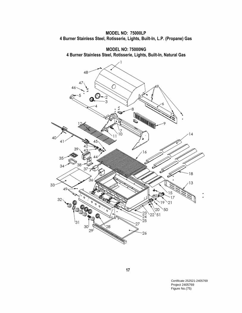
MODEL NO: 75000LP
4 Burner Stainless Steel, Rotisserie, Lights, Built-In, L.P. (Propane) Gas
MODEL NO: 75000NG
4 Burner Stainless Steel, Rotisserie, Lights, Built-In, Natural Gas
17
Certificate 252521-2405769 Project 2405769 Figure No.(75)
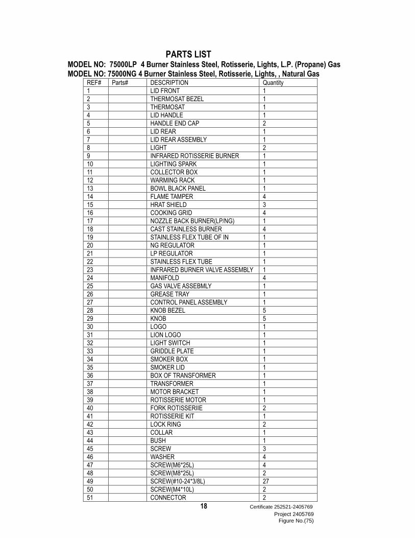
PARTS LIST MODEL NO: 75000LP 4 Burner Stainless Steel, Rotisserie, Lights, L.P. (Propane) Gas
MODEL NO: 75000NG 4 Burner Stainless Steel, Rotisserie, Lights, , Natural Gas REF# Parts# DESCRIPTION Quantity
1 LID FRONT 1
2 THERMOSAT BEZEL 1
3 THERMOSAT 1
4 LID HANDLE 1
5 HANDLE END CAP 2
6 LID REAR 1
7 LID REAR ASSEMBLY 1
8 LIGHT 2
9 INFRARED ROTISSERIE BURNER 1
10 LIGHTING SPARK 1
11 COLLECTOR BOX 1
12 WARMING RACK 1
13 BOWL BLACK PANEL 1
14 FLAME TAMPER 4
15 HRAT SHIELD 3
16 COOKING GRID 4
17 NOZZLE BACK BURNER(LP/NG) 1
18 CAST STAINLESS BURNER 4
19 STAINLESS FLEX TUBE OF IN 1
20 NG REGULATOR 1
21 LP REGULATOR 1
22 STAINLESS FLEX TUBE 1
23 INFRARED BURNER VALVE ASSEMBLY 1
24 MANIFOLD 4
25 GAS VALVE ASSEBMLY 1
26 GREASE TRAY 1
27 CONTROL PANEL ASSEMBLY 1
28 KNOB BEZEL 5
29 KNOB 5
30 LOGO 1
31 LION LOGO 1
32 LIGHT SWITCH 1
33 GRIDDLE PLATE 1
34 SMOKER BOX 1
35 SMOKER LID 1
36 BOX OF TRANSFORMER 1
37 TRANSFORMER 1
38 MOTOR BRACKET 1
39 ROTISSERIE MOTOR 1
40 FORK ROTISSERIIE 2
41 ROTISSERIE KIT 1
42 LOCK RING 2
43 COLLAR 1
44 BUSH 1
45 SCREW 3
46 WASHER 4
47 SCREW(M6*25L) 4
48 SCREW(M8*25L) 2
49 SCREW(#10-24*3/8L) 27
50 SCREW(M4*10L) 2
51 CONNECTOR 2
18 Certificate 252521-2405769 Project 2405769
Figure No.(75)
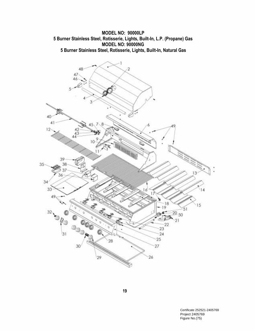
MODEL NO: 90000LP 5 Burner Stainless Steel, Rotisserie, Lights, Built-In, L.P. (Propane) Gas
MODEL NO: 90000NG 5 Burner Stainless Steel, Rotisserie, Lights, Built-In, Natural Gas
19
Certificate 252521-2405769 Project 2405769 Figure No.(75)
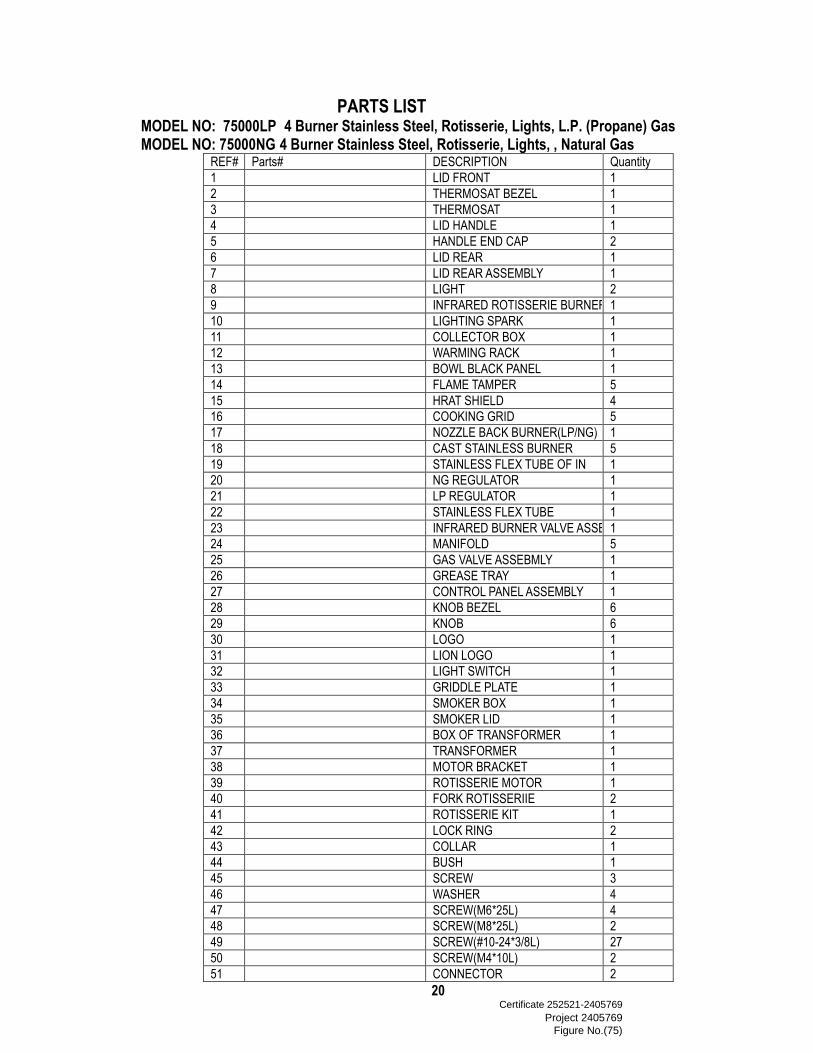
PARTS LIST MODEL NO: 75000LP 4 Burner Stainless Steel, Rotisserie, Lights, L.P. (Propane) Gas
MODEL NO: 75000NG 4 Burner Stainless Steel, Rotisserie, Lights, , Natural Gas REF# Parts# DESCRIPTION Quantity
1 LID FRONT 1
2 THERMOSAT BEZEL 1
3 THERMOSAT 1
4 LID HANDLE 1
5 HANDLE END CAP 2
6 LID REAR 1
7 LID REAR ASSEMBLY 1
8 LIGHT 2
9 INFRARED ROTISSERIE BURNER 1
10 LIGHTING SPARK 1
11 COLLECTOR BOX 1
12 WARMING RACK 1
13 BOWL BLACK PANEL 1
14 FLAME TAMPER 5
15 HRAT SHIELD 4
16 COOKING GRID 5
17 NOZZLE BACK BURNER(LP/NG) 1
18 CAST STAINLESS BURNER 5
19 STAINLESS FLEX TUBE OF IN 1
20 NG REGULATOR 1
21 LP REGULATOR 1
22 STAINLESS FLEX TUBE 1
23 INFRARED BURNER VALVE ASSEMBLY 1
24 MANIFOLD 5
25 GAS VALVE ASSEBMLY 1
26 GREASE TRAY 1
27 CONTROL PANEL ASSEMBLY 1
28 KNOB BEZEL 6
29 KNOB 6
30 LOGO 1
31 LION LOGO 1
32 LIGHT SWITCH 1
33 GRIDDLE PLATE 1
34 SMOKER BOX 1
35 SMOKER LID 1
36 BOX OF TRANSFORMER 1
37 TRANSFORMER 1
38 MOTOR BRACKET 1
39 ROTISSERIE MOTOR 1
40 FORK ROTISSERIIE 2
41 ROTISSERIE KIT 1
42 LOCK RING 2
43 COLLAR 1
44 BUSH 1
45 SCREW 3
46 WASHER 4
47 SCREW(M6*25L) 4
48 SCREW(M8*25L) 2
49 SCREW(#10-24*3/8L) 27
50 SCREW(M4*10L) 2
51 CONNECTOR 2
20 Certificate 252521-2405769
Project 2405769 Figure No.(75)
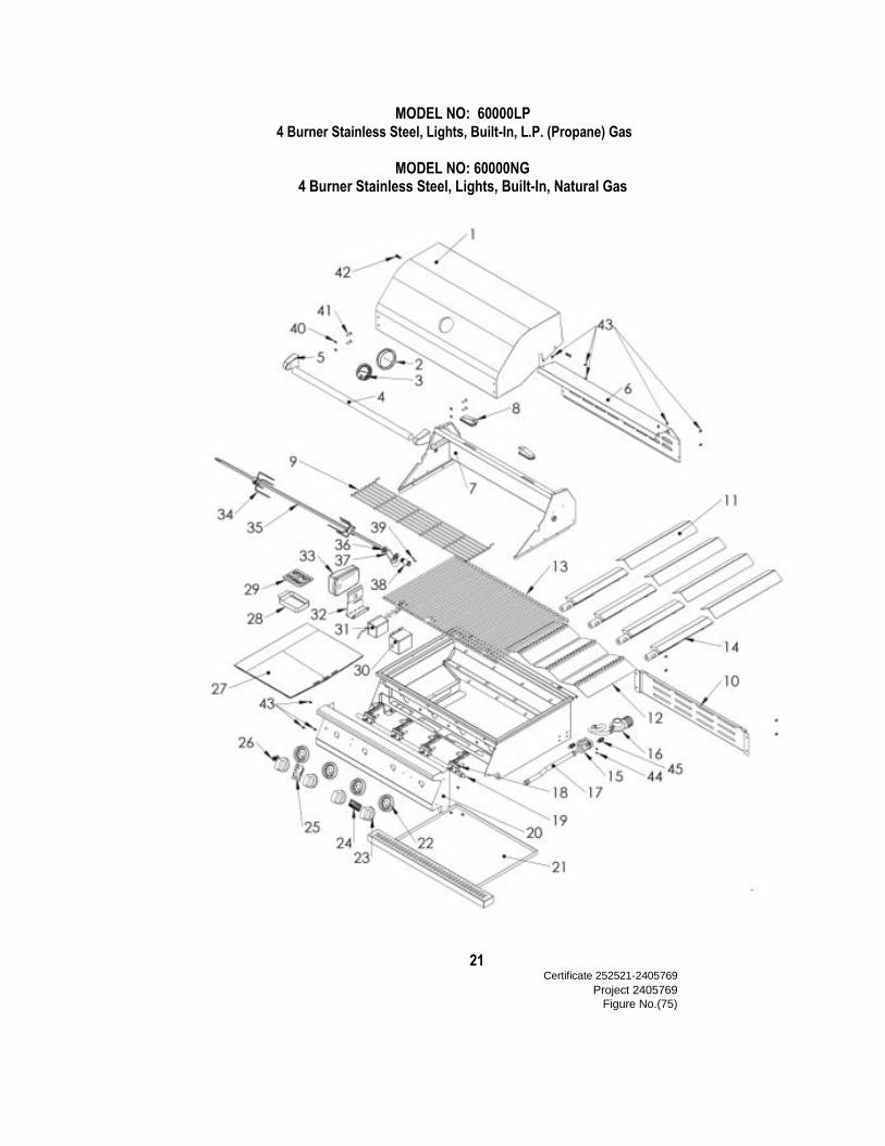
MODEL NO: 60000LP 4 Burner Stainless Steel, Lights, Built-In, L.P. (Propane) Gas
MODEL NO: 60000NG 4 Burner Stainless Steel, Lights, Built-In, Natural Gas
21 Certificate 252521-2405769
Project 2405769 Figure No.(75)

PARTS LIST MODEL NO: 60000LP 4 Burner Stainless Steel, Lights, Built-In, L.P. (Propane) Gas MODEL NO: 60000NG 4 Burner Stainless Steel, Lights, Built-In, Natural Gas
REF# Parts# DESCRIPTION Quantity
1 LID FRONT 1
2 THERMOSAT BEZEL 1
3 THERMOSAT 1
4 LID HANDLE 1
5 HANDLE END CAP 2
6 LID REAR 1
7 LID REAR ASSEMBLY 1
8 LIGHT 2
9 WARMING RACK 1
10 BOWL BLACK PANEL 1
11 FLAME TAMPER 4
12 HRAT SHIELD 3
13 COOKING GRID 4
14 CAST STAINLESS BURNER 4
15 NG REGULATOR 1
16 LP REGULATOR 1
17 STAINLESS FLEX TUBE 1
18 MANIFOLD 4
19 GAS VALVE ASSEBMLY 1
20 CONTROL PANEL ASSEMBLY 1
21 GREASE TRAY 1
22 KNOB BEZEL 4
23 KNOB 4
24 LOGO 1
25 LION LOGO 1
26 LIGHT SWITCH 1
27 GRIDDLE PLATE 1
28 SMOKER BOX 1
29 SMOKER LID 1
30 BOX OF TRANSFORMER 1
31 TRANSFORMER 1
32 MOTOR BRACKET 1
33 ROTISSERIE MOTOR 1
34 FORK ROTISSERIIE 2
35 ROTISSERIE KIT 1
36 LOCK RING 2
37 COLLAR 1
38 BUSH 1
39 SCREW 3
40 WASHER 4
41 SCREW(M6*25L) 4
42 SCREW(M8*25L) 2
43 SCREW(#10-24*3/8L) 27
44 SCREW(M4*10L) 2
45 CONNECTOR 2
22
Certificate 252521-2405769 Project 2405769 Figure No.(75)
Lion Exterior Products, Inc.
Ontario, California 91761
LIMITED WARRANTY Lion Exterior Products, Inc. warrants to the original purchaser at the original site of delivery with proof of purchase
of each Outdoor Gas Grill that when subject to normal residential use, it is free from defects in workmanship and
materials for the periods specified below. This warranty excludes grills used in rental or commercial applications. It
does not apply to rust, corrosion, oxidation or discoloration, which may occur due to moisture or overheating, unless
the affected component becomes inoperable. It does not cover labor or labor related charges. There will be shipping
and handling charge for the delivery of the warranty part(s). Component Warranty Period Cast Stainless Burner ………………………………………………….... Lifetime Stainless Steel Frame, Housing ………………………………………… Lifetime Stainless Steel Cooking Grids …………………………………………... Lifetime Stainless Steel Flame Tamer ……………………………………………. 3 Years Gas Valves and all other parts and components ………………………… 1 Year Our obligation under this warranty is limited to repair or replacement, at our option, of the product during the
warranty period. The extent of any liability of Lion Exterior Products, Inc., under this warranty is limited to repair
or replacement. This warranty does not cover normal wear of parts, damage resulting from any of the following:
negligent use or misuse of the product, use on improper fuel/gas supply, use contrary to operating instructions, or
alteration by any person other than our factory service center The warranty period is not extended by such repair or
replacement.
For customer service, contact the authorized selling dealer immediately. If you need additional information or
assistance, please contact the Lion Exterior Products Inc. 541 East Main St., Ontario CA 91761 or visit lionbbq.com Product repair as provided under this warranty is your exclusive remedy. Lion Exterior Products, Inc. shall not be
liable for any incidental or consequential damages for breach of any express or implied warranty on its products.
Except to the extent prohibited by applicable law, any implied warranty or merchantability or fitness for a particular
purpose on this product to the duration of the above warranty. Some states do not allow the exclusion or limitation of
incidental or consequential damages, or allow limitations on how long an implied warranty lasts, so the above
limitations or exclusions may not apply to you. This warranty gives you specific legal rights, and you may have
other rights, which vary from state to state. Lion Exterior Products Inc. shall not be liable for loss of use of the
barbecue grills, related hardware or other incidental or consequential costs, expense or damages, which may include,
but are not limited to, removal of permanent deck or other custom fixtures or the necessity for crane removal. Any
implied warranty shall have duration equal of the applicable warranty stated above.
Grill Model _______________________________ Grill Serial Number _____________________________ Date of Purchased____________________________ Purchased From___________________________________
23Certificate 252521-2405769 Project 2405769 Figure No.(75)