Onsite Design Manual - City of Sacramento
54
Onsite Design Manual FOR ONSITE DRAINAGE, SEWER, WATER, STORMWATER QUALITY AND EROSION AND SEDIMENT CONTROL MAY 1st, 2020
Transcript of Onsite Design Manual - City of Sacramento

Onsite Design ManualFOR ONSITE DRAINAGE, SEWER, WATER, STORMWATER
QUALITY AND EROSION AND SEDIMENT CONTROL
MAY 1st, 2020

Department of Utilities916-808-14001395 35th AveSacramento, CA 95822
MEMORANDUM
DATE: May 1st, 2020
TO: Engineers, Architects and Developers
SUBJECT: City of Sacramento - Department of Utilities Onsite Design Manual
The Department of Utilities (DOU) hereby establishes the Onsite Design Manual, which provides the DOU’s minimum design standards and guidelines for the planning, design and approval of:
Drainage, sewer and water service connections to City systems,Private onsite grading and drainage systems,Stormwater quality treatment and Low Impact Development (LID) methods,Erosion and Sediment Control (ESC) methods.
The designer is responsible for using the most current version of the Onsite Design Manual posted on the City’s website.
For questions related to any items addressed in this manual please call (916) 808-1400 and ask to speak with an engineer in the Development Review Section.
CITY OF SACRAMENTO:
Approved by: _______________________________William O. Busath, Director of Utilities
Approved by: ________________________________ Tony Bertrand, Engineering and Water Resources Division Manager

Department of Utilities Onsite Design Manual for Onsite Drainage, Sewer, Water, Stormwater Quality Treatment and Erosion and Sediment Control
i 05/01/2020
Table of Contents 1. Purpose ........................................................................................................................... 1
2. Civil Plan Package ........................................................................................................... 2
3. Drainage Services and Onsite Drainage Requirements ................................................... 3
3.1 Drainage Study Requirements ................................................................................... 3
3.1.1 Onsite Project Storage Method (Static Analysis) ..................................................... 4
3.1.2 Rational Method (Static Analysis) ............................................................................ 5
3.1.3 Onsite Computer Model (Dynamic Analysis) ........................................................... 6
3.2 Drainage Service Requirements ................................................................................ 7
3.2.1 Mitigation Required ................................................................................................. 8
3.3 Grading/Drainage Plans Shall Include the Following (at a minimum) ......................... 8
3.4 Paved Area and Surface Drainage Requirements ...................................................... 9
3.5 Finished Floor Requirements ....................................................................................10
3.6 Drain Pipe Requirements ..........................................................................................10
3.7 Drain Inlets ................................................................................................................12
3.8 Point of Service Manholes and Cleanouts .................................................................12
3.9 Drainage Service Taps to City System ......................................................................13
3.10 Detention & Retention .............................................................................................14
4. Sewer Services ...............................................................................................................15
4.1 Sewer Study Requirements.......................................................................................15
4.2 Sewer Service Requirements ....................................................................................16
4.3 Sewer Plans Shall Include the Following (at a minimum) ..........................................17
4.4 Sewer Service Pipe Requirements ............................................................................18
4.5 Service Cleanouts and Manholes ..............................................................................18
4.6 Sewer Service Taps to City System ..........................................................................19
4.7 Combined Sewer System (CSS) Development Fees ................................................19
5. Water Services ...............................................................................................................21
5.1 Water Study Requirements .......................................................................................21
5.2 Water Service Requirements ....................................................................................21
5.3 Water Plans Shall Include the Following (at a minimum) ...........................................23
5.4 Water Service Pipe Requirements ............................................................................24

Department of Utilities Onsite Design Manual for Onsite Drainage, Sewer, Water, Stormwater Quality Treatment and Erosion and Sediment Control
ii 05/01/2020
5.5 Point of Service Meters and Backflow Devices..........................................................24
5.6 Fire Hydrants ............................................................................................................25
5.7 Water Service Taps to City System ...........................................................................26
6. Private Facility Separation Requirements .......................................................................27
7. Stormwater Quality Requirements ..................................................................................28
7.1 Stormwater Quality Post Construction Requirements ................................................28
7.2 Low Impact Development (LID) Design .....................................................................29
7.3 Hydromodification Management Plan Requirements .................................................30
7.4 Trash Control Measures ............................................................................................30
8. State General Permit Requirements ...............................................................................31
9. Grading, Erosion and Sediment Control ..........................................................................32
10. Flood Related Requirements ..........................................................................................33
APPENDIX ...............................................................................................................................34
Figure 1 – Drainage Basin Map.......................................................................................35
Figure 2 – Sewer Basin Map ...........................................................................................36
Figure 3 – Water Purveyor Map ......................................................................................37
Figure 4 – Type I DI ........................................................................................................38
Figure 5 – Type II DI .......................................................................................................39
Figure 6 – Water Tap Notes ............................................................................................40
Figure 7 – General Notes ................................................................................................42
Figure 8 – General Water Notes .....................................................................................44
Figure 9 – Erosion and Sediment Control Notes .............................................................46
Figure 10 – Onsite Project Storage .................................................................................48

Section 1. Purpose Onsite Design Manual
1 05/01/2020
1. Purpose For properties within the City of Sacramento, this on-site design manual provides the Department of Utilities (DOU) minimum design standards and guidelines for the planning, design and approval of:
• Drainage, sewer and water service connections to City systems, • Private onsite grading and drainage systems, • Stormwater quality treatment and Low Impact Development (LID) methods, • Erosion and Sediment Control (ESC) methods.
These standards and guidelines may be amended periodically. It is the designer’s responsibility to check the City Department of Utilities website for amendments and to use the latest version of this manual. The design of public improvements are required to comply with the City’s Design and Procedures Manual (DPM). Both the Onsite Design Manual and Utilities sections of the DPM can be found online here: https://www.cityofsacramento.org/Utilities/Development-Standards
Compliance with these standards does not relieve a designer from the responsibility to apply conservative and sound professional judgment. Designers are expected to consider related issues, such as environmental impact, maintenance of pedestrian and vehicular traffic patterns, constructability, system maintenance, and sustainability principles in addition to any building code requirements. Additional information concerning the requirements for and design of the items specified in this manual may be obtained from the Department of Utilities, Development Services Section, telephone (916) 808-7890. The City recognizes there are occasions when it may be necessary to vary from the standards and guidelines outlined herein. Designers shall complete and submit a variance request for all proposed deviations from these standards (refer to Plate 9-3 “Variance Request Form” in Section 9 of the DPM).

Section 2. Civil Package Onsite Design Manual
2 05/01/2020
2. Civil Plan Package Commercial projects shall submit an onsite civil plan set, stamped and signed by a Licensed Civil Engineer in the State of California for approval of water, sewer and drainage service connections to the City’s systems; in addition to onsite grading, drainage system and stormwater quality treatment methods (including ESC). The typical civil plan set shall include:
1. Title sheet with City standard general notes, project address, site plan, vicinity map, official City benchmark, utility contacts, flood zone information, building square footage, site acreage, total disturbed area, increase in impervious area, sheet index and a state issued WDID number (if applicable, see Section 8 below).
2. Topographic sheet with elevations tied to an official City of Sacramento benchmark, showing property lines, right-of-way lines, easements and existing utilities. Adjacent off-site topography shall also be shown to the extent necessary to determine the impacts to surface drainage paths.
3. Grading sheet showing existing and proposed elevations, grade breaks, finished floor elevations and overland flow release arrows; pavement information, including curbs, gutters and sidewalks; and surface stormwater quality features. Cross sections showing existing and proposed grading, fences, walls, property lines, right-of-way, easements, drainage flow arrows, utilities, dimensions, and finished pavement sections and base information.
4. Drainage and sewer sheet detailing on-site drainage and sewer pipe systems, including slope/length/size, pipe material and bedding information. Location of service connections, invert and rim elevations of drainage inlets, manholes, cleanouts and other structures (including any subsurface stormwater quality features). Details of any structures not per City standard.
5. Water sheet showing on-site fire, domestic and irrigation systems. Include City standard general water notes, location of service connections, meters and backflow prevention devices.
6. Erosion and Sediment Control Plan with City standard erosion and sediment control notes, location of best management practices selected, and associated details.
The items listed above may be combined into common plan sheets, provided the sheets remain clear and legible. For a copy of all City standard general notes referenced above, see Figure 7. The onsite Civil plan set addresses permitting requirements within the property. Any work within the public right-of-way (such as water, sewer or drainage taps) must be approved either through an encroachment permit or offsite improvement plans.

Section 3. Drainage Service and Onsite Drainage Requirements Onsite Design Manual
3 05/01/2020
3. Drainage Services and Onsite Drainage Requirements The Department of Utilities is responsible for operating and maintaining the public drainage system within the City of Sacramento, which includes a combined sewer system (CSS) and separated stormwater system. Most of the City service area is ultimately pumped into nearby rivers, creeks and channels which are maintained by others. See Figure 1 for a map showing the sump locations, and boundaries of the combined and separated drainage system basins. All onsite drainage systems shall be privately owned and maintained, including the portion of the private storm drain line located within the public right-of-way; see City Code Section 13.08.020 and 13.08.210. Private drainage systems proposed to connect to the City’s drainage system shall be designed and constructed to meet the requirements of this manual; in addition to the standards specified in Section 11 of the DPM. At the discretion of the DOU, projects reviewed and approved by the California Division of State Architects (DSA) or California Office of Statewide Health Planning and Development (OSHPD), may not be subject to the following sections of this manual:
• Section 3.5 Finished Floor Requirements • Section 3.6 Drain Pipe Requirements
All onsite drainage systems shall be separate from private sewer systems, with separate drainage connections to City mains, including systems in the CSS; see City Code Section 13.08.220. Certain projects (as determined by the DOU) may require the submittal of grading certification letters prepared by the engineer of record or licensed land surveyor; stating that the site has been graded as specified per the approved plans and/or listing the variances that occur. In these cases, a letter shall be submitted to the City building inspector certifying pad elevations prior to footing inspection and then a final grading certification shall be submitted prior to the project’s final inspection. Or if no building is involved, a final grading certification letter shall be submitted to the DOU engineer that approved the plans, once grading work is complete. When required by the DOU, a note specifying this requirement shall be placed on the approved grading plan sheets, see item 14 in Section 3.3 below. 3.1 Drainage Study Requirements An onsite drainage study is required when a site contributes drainage to the City’s storm drain system or CSS, and:
1. Mitigation is required (Section 3.2.1), and/or 2. Onsite drainage system analysis is required (Section 3.6)
If public drainage mains are being designed, see Plate 11-3 “Drainage Design Report Alternatives” of the DPM for guidance on when an offsite drainage study will be required and Section 11.3.5 of the DPM for requirements related to the offsite drainage study for public mains. If a drainage study for public mains

Section 3. Drainage Service and Onsite Drainage Requirements Onsite Design Manual
4 05/01/2020
is required, it may also include the onsite project drainage design, eliminating the requirement for a separate onsite drainage study.
For onsite drainage studies, the designer may use either a static or dynamic analysis for mitigation sizing and drainage system design as described in the Sections 3.1.1, 3.1.2 and 3.1.3. The same method (either static or dynamic) must be used for the project’s entire drainage analysis. Any required drainage design study shall be completed and approved prior to the approval of onsite plans and shall demonstrate conformance with mitigation (Section 3.2.1), finished floor (Section 3.5) and drain pipe criteria (Section 3.6).
An onsite drainage study shall include the following (at a minimum): • A written description of the project.• Reference to the City drainage basin that contains the project and regional study if applicable.• Elevation datum used in study and for all referenced information.• 10 and 100-year event tailwater elevations and sources.• Summary of proposed drainage improvements.• Attached excerpts of studies and other information that may be referenced.• Summary of the methods used for the drainage study.• Copies of calculations, spread sheets or computer models.• An exhibit that:
o Depicts existing and proposed impervious areas.o Shows proposed detention methods and locations including the volume of storage provided.o Depicts the onsite drainage system and connection points to the City system; including
drainage inlet and manhole locations; and pipe lengths, sizes, slopes and invert elevations.o Denotes the elevation and location of the controlling overland release point(s) on the City
drainage system. See Section 11.1.3 of the DPM for a definition of overland release point.o Depicts onsite drainage shed areas, includes overland release arrows to the public right-of-
way and calls out drainage shed breakpoint elevations.o Denotes finished floor elevations for all proposed buildings.
3.1.1 Onsite Project Storage Method (Static Analysis) Projects required to provide drainage mitigation (see Section 3.2.1), not performing a dynamic analysis, shall use the following procedure to size the detention volume and outlet orifice:
1. If required by the DOU, the designer must calculate and replace the volume of storage removedby the project at and below the existing 100-year event hydraulic grade line (HGL) of the City’sdrainage system, in addition to mitigating for increased imperviousness.
2. To mitigate for increased imperviousness, determine which City drainage basin the projectresides in (Figure 1) and the associated storage required per acre of increased imperviousnessfor the 100-year event (as specified in Figure 10).
3. Determine the additional acreage of impervious surface resulting from the project. All surfacesshall be considered completely pervious or impervious. Impervious surfaces generally include

Section 3. Drainage Service and Onsite Drainage Requirements Onsite Design Manual
5 05/01/2020
roof-tops and traditional pavement. Green roofs, pervious pavement, gravel, pavers with pervious base and joints shall be considered entirely pervious.
4. Multiply the additional impervious area by the 100-year event storage required per acre. If required, add to the flood replacement volume determined in step 1. The storage volume shall be completely contained at least one-foot above the Invert elevation of the receiving City main.
5. If a portion of the 100-year event detention volume is being stored within vehicular and/or pedestrian access surfaces, calculate the 10-year event storage volume and ensure it is completely contained within underground pipes and/or designated detention facilities. To determine the 10-year event storage volume, multiply the additional impervious area by the 10-year event storage required per acre for the basin (as specified in Figure 10).
6. Determine the orifice diameter (d) in inches for metering the stored discharge to the City drainage system (see Equation 3-1 and Figure 3-1):
7. Calculate the maximum head (h) in feet upstream of the orifice, by subtracting the elevation at the center of the orifice from the overland release flow line elevation for the project site (see Figure 3-1),
8. Determine orifice flow (Q) in CFS, by multiplying the Nominal Capacity of the City drainage basin (as specified in Figure 10) by the entire area draining to the detention pond,
9. Determine the orifice diameter in inches using Equation 3-1.
Equation 3-1 𝒅𝒅 = 𝟔𝟔.𝟏𝟏𝟏𝟏� 𝑸𝑸√𝒉𝒉
Figure 3-1 Onsite Project Storage Discharge
3.1.2 Rational Method (Static Analysis) Projects required to provide calculations sizing the onsite drainage system pipes (see Section 3.6), not performing a dynamic analysis, shall use the rational method as specified below; only a 10-year event storm analysis is required. The 10-year event starting HGL elevation shall be obtained as follows:

Section 3. Drainage Service and Onsite Drainage Requirements Onsite Design Manual
6 05/01/2020
• For gravity flow situations without onsite detention, the starting HGL shall be obtained from a previously approved City storm drain master plan that includes the project site. If an approved master plan does not exist, assume the HGL is 0.5-feet above the most downstream adjacent City drainage inlet grate elevation. If there is no gutter, assume the HGL is the lowest adjacent street or alley surface elevation fronting the project site.
• For projects that include onsite dry detention areas, assume the starting HGL for each pipe segment connected to a detention facility is the invert elevation at the segments point of connection to the facility. For onsite detention areas that include a permanent pool, the starting HGL for each pipe segment connected to the pool, is the permanent pool water surface elevation.
Drainage studies utilizing the rational method shall demonstrate all proposed private “drainage pipe” meets the criteria specified in Section 3.6 of this manual, and shall include:
1. Applicable runoff for drainage shed areas using Equations 3-2 & 3-3, and 2. 10-year event HGL throughout the analyzed system utilizing Manning’s equation
Equation 3-2 𝑄𝑄 = 𝐶𝐶𝑖𝑖𝐴𝐴𝑆𝑆
Equation 3-3 𝑖𝑖 = 𝑎𝑎𝑡𝑡𝑏𝑏 Where: Q = Peak flow rate to a particular node (CFS) C = Runoff coefficient (unit-less, Refer to Table 3-1) i = Rainfall intensity (inches/hour) AS = Shed area draining to a particular Node (acres) a = Rainfall intensity coefficient = 8.10 (10-year event) and 14.465 (100 -year event) b = Rainfall intensity coefficient = -0.573 (10-year event) and -0.602 (100-year event) t = Time of concentration (minutes) = Inlet Time + Time thru pipe/channel to a particular
Node (Refer to Table 3-1 for Inlet Time) Designer shall use an area weighted average of pervious and impervious areas for calculating the C factor and Inlet Time.
Table 3-1 Runoff Coefficients and Inlet Times Imperviousness/ Land
Use Runoff
Coefficient C Inlet Time ti
Proposed/Existing Development Impervious areas 0.95 5
Pervious areas 0.40 10
3.1.3 Onsite Computer Model (Dynamic Analysis) Projects may use a computer dynamic model for sizing onsite detention and/or drainage pipe. The model results shall demonstrate that finished floor elevations meet the requirements specified in Section 3.5 and that any proposed drainage pipe meets the criteria specified in Section 3.6.

Section 3. Drainage Service and Onsite Drainage Requirements Onsite Design Manual
7 05/01/2020
The onsite computer dynamic model shall be setup in accordance with the Level Two – Dynamic Modeling criteria specified in Section 11.3.5.6 of the DPM. 3.2 Drainage Service Requirements Each lot or parcel connecting to the City’s separate drainage system or CSS shall have its own separate drainage service connection; except for special cases where a common service is authorized by the DOU director. If a common drainage service is authorized, appropriate private drainage easements must be dedicated/granted and a maintenance agreement (specifying future maintenance requirements and cost sharing), which has been reviewed and approved by the DOU, must be recorded prior to approval of plans that allow construction of the service. Drainage services connected to the City’s separate drainage system or CSS shall not cross property lines unless appropriate private drainage easements have been dedicated/granted. If easements (for common drainage services or drainage services crossing property lines) can’t be dedicated/granted due to common property ownership, a conveyance of easement agreement with the City or note on the final map regarding future easements is required. Drainage services shall gravity flow to the City system. If a force main is required for the private onsite piping, the force main must discharge to a point of service manhole or other structure up stream of the point of service allowing for gravity flow to the City’s drainage system. For a definition of the drainage point of service see item 3 in Section 3.8 below. Drainage services within the public right-of-way or City easements shall not run parallel with the public right-of-way or City easement boundary. Perpendicular crossings of City easements may be allowed on a case by case basis; however, a minimum of 1-foot vertical separation (measured from edge of pipe to edge of pipe) for any services crossing City mains is required. Unused drainage services shall be abandoned per the requirements of the City Standard Specifications. City manhole penetrations shall be plugged with concrete and abandoned pipe shall either be removed or filled with concrete or controlled density backfill (CDF). Swimming pools shall have no permanent connection to the City’s drainage system and may only discharge dechlorinated water if granted permission from the DOU director; per City Code Section 13.04.510. No new permanent groundwater dewatering to the City’s separated drainage system or CSS shall be allowed. Temporary groundwater dewatering may be allowed during construction; authorized either through an approval letter from the DOU or the execution of a Memorandum of Understanding (MOU), see City Code Sections 13.08.110 & 13.16.070.
• All groundwater discharges to the separated drainage system must also obtain an individual National Pollutant Discharge Elimination System (NPDES) permit from the California Regional Water Quality Board.

Section 3. Drainage Service and Onsite Drainage Requirements Onsite Design Manual
8 05/01/2020
• All groundwater discharges to the separated sewer system or CSS must also be permitted by theSacramento Regional Sanitation Sewer District.
For additional information related to ground water discharges, see Sections 9.2.10 & 11.2.7 of the DPM.
3.2.1 Mitigation Required All stormwater and surface runoff drainage impacts resulting from any improvement or development (adding more than 500 square feet of increased imperviousness and/or removing more than 100 cubic feet of flood volume when fully built-out) must be fully mitigated to ensure the improvement or development does not negatively affect the function of the separated stormwater system or CSS; see City Code Section 13.08.145. To sufficiently demonstrate compliance with this requirement, a drainage design study is required.
If the project site is located in a basin with a City approved drainage master plan, that mitigated for planned development (e.g. basin that contains a regional pond), the project may add impervious area up to the percentage allotted and remove 100-year event storage to the extent accounted for in the master plan without mitigating. All additional impervious area and flood storage removal must be mitigated, in which case a drainage study as described in Section 3.1 is required.
Impervious area credit can be given for sites that were partially or completely demolished in preparation for the specific project requesting the credit; or:
• In the separated drainage system - If the demolition occurred within the last three years,• In the Combined Sewer System – If the demolition occurred after July 1990.
Sufficient evidence such as photographs, aerial imagery, building permits, etc. shall be presented for projects requesting credit.
Projects in the CSS may also mitigate their drainage impacts as specified in Section 9.4.5 of the DPM.
3.3 Grading/Drainage Plans Shall Include the Following (at a minimum) 1. The nature and extent of all street and/or alley improvements along the entire frontage of the
proposed project site. These improvements include curb, gutter, sidewalk, pavement, gutterdrains, roadside ditches, etc.
2. Public water, storm drain, and sanitary sewer lines and/or facilities located adjacent to orpassing through the project site.
3. The locations and sizes of all onsite drainage inlets, manholes, and structures including theirinvert and surface elevations.
4. The layout of connecting pipes including their size, length, invert elevations, slope, material, andbedding material.
5. The location of the point of service manhole (or cleanout), see Section 3.8, including its size andinvert/rim elevations.
6. The pipe size and location of any roof drainage discharge points or connections to the onsitedrainage system.
Section 3. Drainage Service and Onsite Drainage Requirements Onsite Design Manual
9 05/01/2020
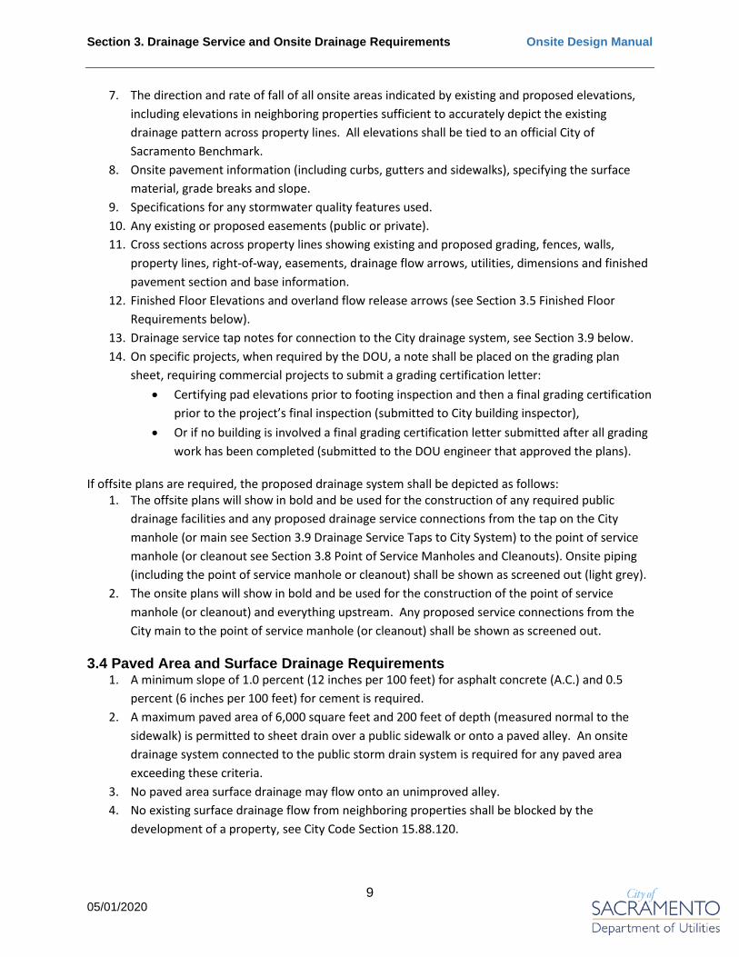
7. The direction and rate of fall of all onsite areas indicated by existing and proposed elevations, including elevations in neighboring properties sufficient to accurately depict the existing drainage pattern across property lines. All elevations shall be tied to an official City of Sacramento Benchmark.
8. Onsite pavement information (including curbs, gutters and sidewalks), specifying the surface material, grade breaks and slope.
9. Specifications for any stormwater quality features used. 10. Any existing or proposed easements (public or private). 11. Cross sections across property lines showing existing and proposed grading, fences, walls,
property lines, right-of-way, easements, drainage flow arrows, utilities, dimensions and finished pavement section and base information.
12. Finished Floor Elevations and overland flow release arrows (see Section 3.5 Finished Floor Requirements below).
13. Drainage service tap notes for connection to the City drainage system, see Section 3.9 below. 14. On specific projects, when required by the DOU, a note shall be placed on the grading plan
sheet, requiring commercial projects to submit a grading certification letter: • Certifying pad elevations prior to footing inspection and then a final grading certification
prior to the project’s final inspection (submitted to City building inspector), • Or if no building is involved a final grading certification letter submitted after all grading
work has been completed (submitted to the DOU engineer that approved the plans).
If offsite plans are required, the proposed drainage system shall be depicted as follows: 1. The offsite plans will show in bold and be used for the construction of any required public
drainage facilities and any proposed drainage service connections from the tap on the City manhole (or main see Section 3.9 Drainage Service Taps to City System) to the point of service manhole (or cleanout see Section 3.8 Point of Service Manholes and Cleanouts). Onsite piping (including the point of service manhole or cleanout) shall be shown as screened out (light grey).
2. The onsite plans will show in bold and be used for the construction of the point of service manhole (or cleanout) and everything upstream. Any proposed service connections from the City main to the point of service manhole (or cleanout) shall be shown as screened out.
3.4 Paved Area and Surface Drainage Requirements 1. A minimum slope of 1.0 percent (12 inches per 100 feet) for asphalt concrete (A.C.) and 0.5
percent (6 inches per 100 feet) for cement is required. 2. A maximum paved area of 6,000 square feet and 200 feet of depth (measured normal to the
sidewalk) is permitted to sheet drain over a public sidewalk or onto a paved alley. An onsite drainage system connected to the public storm drain system is required for any paved area exceeding these criteria.
3. No paved area surface drainage may flow onto an unimproved alley. 4. No existing surface drainage flow from neighboring properties shall be blocked by the
development of a property, see City Code Section 15.88.120.

Section 3. Drainage Service and Onsite Drainage Requirements Onsite Design Manual
10 05/01/2020
5. A property shall not surface drain or have a piped drainage system that crosses property lines without the dedication of appropriate private drainage easements.
6. Any increase in impervious area must be mitigated per the requirements of Section 3.2.1.
3.5 Finished Floor Requirements Finished floor elevations shall meet the following requirements (see Plate 11-2 of the DPM):
• Greenfield Development (projects with new or extended public road(s)): The finished floor of new structures shall be at least 12-inches above the highest adjacent 100-year event HGL of the City’s drainage system and at least 18-inches above the controlling overland release point in the public right-of-way. See Section 11.1.3 of the DPM for a definition of overland release point.
• Infill Development (projects without new or extended public road(s)): The finished floor of new structures shall be at least 6-inches above the highest adjacent 100-year event HGL of the City’s drainage system and at least 12-inches above the controlling overland release point in the public right-of-way.
The 100-year event HGL can be obtained from a City drainage masterplan for the appropriate basin, or if none exists the HGL can be assumed to be one-foot above the most downstream adjacent City drainage inlet. If there is no adjacent City drainage system, assume the 100-year event HGL is one-foot above the lowest adjacent street or alley surface elevation fronting the project site. All onsite drainage sheds (excluding landscape) shall be designed such that, if all drainage inlets are plugged, the overland flow will cascade downstream to release to a public right-of-way or drainage easement on a neighboring property (a four-inch minimum difference is required between high and low breakpoints of each shed area). Overland flow release arrows shall be plotted on the plans. Finished floors shall be set a minimum of four-inches above the highest adjacent drainage shed breakpoint elevation in addition to the requirements specified above. See Section 11.7 of the DPM for specifics related to overland release requirements within the public right-of-way. 3.6 Drain Pipe Requirements
1. Private “drainage pipe” shall be sized at a minimum, to keep the 10-year event HGL below vehicular and/or pedestrian access surfaces. Projects over two acres are required to submit a drainage study that sizes the onsite drainage system (see Section 3.1 for drainage study requirements).
2. The minimum diameter of drainage pipe shall be 6-inches, with three exceptions: • When through sidewalk drains (per City Standard Drawing T-31 or T-32) are allowed, • For landscape areas and roof downspouts, • When smaller pipes are required to restrict flows for onsite detention purposes.
3. From the drainage point of service to the connection on the City drainage system, the depth of cover measured from top of the drainage pipe to ground surface shall be a minimum of 4-feet.

Section 3. Drainage Service and Onsite Drainage Requirements Onsite Design Manual
11 05/01/2020
If a drainage pipe cannot meet this requirement the cover may be reduced to the maximum achievable.
4. Drainage pipe that has less than 1.5-feet of cover, shall be either: • Polyvinyl chloride (PVC) C900 pipe with controlled density backfill (CDF), • Reinforced concrete or ductile iron pipe.
In no case shall drainage pipe have less than 6 inches of cover and/or extend within the top 2-inches of subgrade in paved areas. Drainage pipe in landscaped areas, that will not support heavy equipment, are not subject to any depth of cover requirement.
5. Drainage pipe shall have a uniform slope and be placed on a firm bed of earth with uniform support throughout the entire length of pipe as specified in plumbing code. When performing a static analysis (as specified in Section 3.1.2), all pipe sections (other than oversized pipe specifically used for detention purposes) shall be designed for gravity flow situations, regardless of if their flow is ultimately restricted for detention purposes. The slope shall be set such that the flow velocity is not less than 2 feet per second or more than 10 feet per second, when the pipes are 80% full, with a friction coefficient (n) of 0.015 (required for all pipe types to account for minor losses). When performing a dynamic analysis (see Section 3.1.3) exceptions to the flow velocity requirements may be allowable, as determined by the DOU. The minimum and maximum pipe slopes are as follows:
Table 3.1 – Minimum Drainage Pipe Slope
*Velocity is for pipes flowing 80% full with a friction coefficient (n) of 0.015
6. Drainage pipe material in private storm drain systems shall comply with the approved drainage pipe material specified in Section 26-4 of the City of Sacramento Standard Specifications, with two exceptions:
• Landscaped areas with drainage pipe less than 6-inches in diameter may use single wall corrugated drainage pipe or other approved alternative pipe material.
• Oversized drainage pipe used for detention purposes may be either high-density polyethylene (HDPE) or aluminized steel type 2 or polymer coated corrugated metal pipe (CMP).
Pipe Diameter (Inches)
Minimum Slope (Velocity*=2 fps)
Maximum Slope (Velocity*=10 fps)
4 0.01 0.215 6 0.005 0.125 8 0.0035 0.085
10 0.0025 0.063 12 0.0020 0.050 15 0.0015 0.037 18 0.0012 0.029 21 0.001 0.024 24 0.0008 0.020
Section 3. Drainage Service and Onsite Drainage Requirements Onsite Design Manual
12 05/01/2020
7. All 6-inch and larger drainage pipe (excluding fusion welded solid wall HDPE) shall haveelastomeric gasket joints, providing a water tight seal. All joints shall meet the standards listedin Section 10-19 of the City Standard Specifications.
8. Drainage inlets, manholes or cleanouts are required at all drainage pipe angle points, andwherever a connection to the drainage system occurs. Manholes shall comply with therequirements specified in Section 11.5 of the DPM.
3.7 Drain Inlets 1. Public drainage inlets installed in City streets or alleys shall meet the requirements specified in
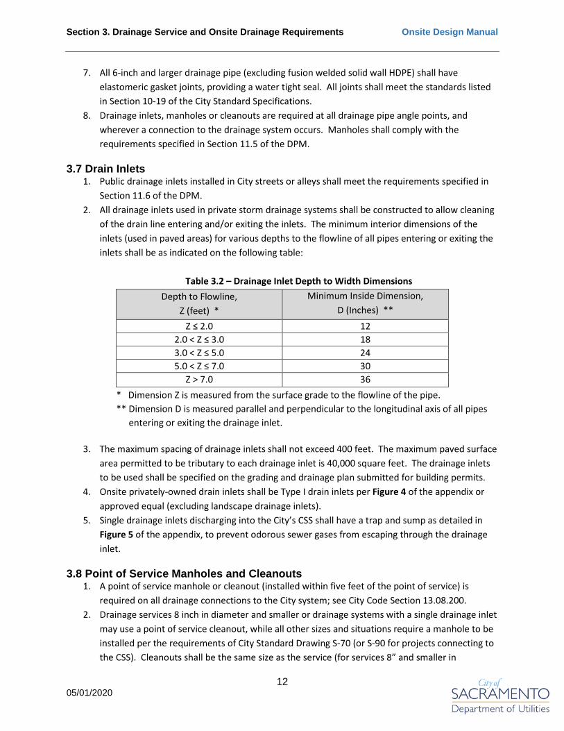
Section 11.6 of the DPM.2. All drainage inlets used in private storm drainage systems shall be constructed to allow cleaning
of the drain line entering and/or exiting the inlets. The minimum interior dimensions of theinlets (used in paved areas) for various depths to the flowline of all pipes entering or exiting theinlets shall be as indicated on the following table:
Table 3.2 – Drainage Inlet Depth to Width Dimensions Depth to Flowline,
Z (feet) * Minimum Inside Dimension,
D (Inches) ** Z ≤ 2.0 12
2.0 < Z ≤ 3.0 18 3.0 < Z ≤ 5.0 24 5.0 < Z ≤ 7.0 30
Z > 7.0 36 * Dimension Z is measured from the surface grade to the flowline of the pipe.** Dimension D is measured parallel and perpendicular to the longitudinal axis of all pipes
entering or exiting the drainage inlet.
3. The maximum spacing of drainage inlets shall not exceed 400 feet. The maximum paved surfacearea permitted to be tributary to each drainage inlet is 40,000 square feet. The drainage inletsto be used shall be specified on the grading and drainage plan submitted for building permits.
4. Onsite privately-owned drain inlets shall be Type I drain inlets per Figure 4 of the appendix orapproved equal (excluding landscape drainage inlets).
5. Single drainage inlets discharging into the City’s CSS shall have a trap and sump as detailed inFigure 5 of the appendix, to prevent odorous sewer gases from escaping through the drainageinlet.
3.8 Point of Service Manholes and Cleanouts 1. A point of service manhole or cleanout (installed within five feet of the point of service) is
required on all drainage connections to the City system; see City Code Section 13.08.200.2. Drainage services 8 inch in diameter and smaller or drainage systems with a single drainage inlet
may use a point of service cleanout, while all other sizes and situations require a manhole to beinstalled per the requirements of City Standard Drawing S-70 (or S-90 for projects connecting tothe CSS). Cleanouts shall be the same size as the service (for services 8” and smaller in

Section 3. Drainage Service and Onsite Drainage Requirements Onsite Design Manual
13 05/01/2020
diameter, otherwise an 8” cleanout is required), and installed per the requirements of City Standard Drawing S-265.
3. The drainage point of service is defined as:• Back of curb for public right-of-way with a separated landscaping strip, otherwise the
back of sidewalk. Cleanouts or manholes are to be installed in the landscape strip or, ifnone exists, at the back of sidewalk (property side),
• For alleys; the edge of the public right-of-way. Cleanouts are to be installed just withinthe alley edge, manholes just outside the alley edge,
• For City drainage mains in easements; on the main. Manholes and cleanouts shall beinstalled just outside of the easement boundary.
3.9 Drainage Service Taps to City System Drainage service taps to the City’s separated drainage system shall all be made to a City manhole regardless of the drainage service size. If there is not an existing City manhole at the tap location, a new City manhole (meeting the specifications of Section 11.6.2 of the DPM) shall be installed at the developer’s/owners’ expense.
All drainage service taps in the CSS shall be to a City manhole with one exception; if there is no existing manhole to tap and the tap is smaller than 8-inch in diameter and not “size on size” (e.g. 6-inch service tap to 6-inch City main), a direct tap by City crews may be allowed for a fee on a case by case basis. All tap fees (for taps to be installed by City crews) must be paid at the 3rd floor public counter at 300 Richards Blvd., a minimum of two weeks prior to the tap installation date. All direct taps shall be perpendicular to City mains from the tap to the point of service.
Drainage service taps to City drainage inlets are strictly prohibited.
All taps to the City drainage system shall be the same size or larger than the largest diameter pipe entering the point of service manhole or cleanout; except in cases where oversized pipe is being used for onsite detention or a smaller pipe downstream of the point of service is being used to restrict flows. The minimum diameter drainage tap to the City drainage system shall be 4-inch.
Drainage service taps and pipe (from the tap to the point of service) shall have a minimum horizontal separation (measured from edge of pipe to edge of pipe) of 3-feet from parallel drainage, sewer and water service pipes and 5-feet from parallel City mains. Drainage services shall pass below any water mains or water service pipes when crossings occur. Upstream of the point of service, separation of private service lines is governed by plumbing code; however, separation from parallel City mains shall remain at a minimum of 5 feet. Services crossing City mains shall have a minimum of 1-foot vertical separation (measured from edge of pipe to edge of pipe).
All taps to manholes must have at least 1-foot of manhole wall between connection openings into the manhole to protect the integrity of the manhole.

Section 3. Drainage Service and Onsite Drainage Requirements Onsite Design Manual
14 05/01/2020
All taps to the City drainage system shall be approved either through an encroachment permit or offsite plan set. During construction, the tap installation shall be coordinated through the assigned Public Works inspector.
Taps and manholes shall be installed by a private contractor, except for the case in the CSS when a direct tap by City crews is allowed. For direct taps by City crews, the private contractor shall provide all excavation and expose the City main for tapping per City Standard Specification requirements. City crews will perform the tap on the main and install an Insert-A-Tee. The private contractor will then provide and install the drainage service line, backfill the trench and provide surface restoration.
3.10 Detention & Retention Onsite detention or retention is required when the construction of a project (without mitigation) will result in additional drainage runoff to the public right-of-way or drainage system that was not accounted for in an approved City drainage master plan, see Section 3.2.1.
The onsite detention volume shall be sized, and outflows shall be restricted as required, per an approved drainage study, see Section 3.1. Required detention volumes may be reduced by implementing LID features, see Section 7.2 below.
The 10-year event detention volume must be completely contained within underground pipes and designated detention facilities. Flood water from storms in excess of the 10-year event may be temporarily stored in parking lots, walkways, planters and other onsite areas. If flood water depth in parking areas and/or walkways is expected to exceeds 6-inches, warning signs shall be placed along the boundaries of the storage area, warning of the potential flood hazard.
Onsite retention ponds shall be sized per an approved drainage study. They shall only be allowed where a soil study (by a licensed geotechnical engineer in the state of California) has been provided and the soil is shown to allow a maximum draw down time of 48 hours. The soil study shall also demonstrate there are no groundwater related issues.
A porosity of 40% shall be assumed for gravel used to fill onsite detention/retention basins.
Projects providing more than 250 cubic feet of onsite drainage detention volume require a maintenance agreement that includes provisions for funding all on-going maintenance in perpetuity and in a manner that is acceptable to the DOU. Maintenance agreements shall be accepted by DOU prior to approval of plans.

Section 4. Sewer Services Onsite Design Manual
15 05/01/2020
4. Sewer ServicesThe City owns and maintains the public sewer systems for about 65 percent of the geographical area of the City. The balance of the City residents and businesses are served by the Sacramento Area Sewer District (SASD). Flows conveyed by the City sewer systems are routed to the Sacramento Regional Wastewater Treatment Plant (SRWTP) for treatment and disposal via an Interceptor system consisting of large diameter pipes and pump stations. The Interceptor system and the SRWTP, located just south of the City limits, are owned and operated by the Sacramento Regional County Sanitation District (SRCSD).
The DOU is responsible for operating and maintaining the public Sewer System within the City service area, which includes a combined sewer system (CSS), and a separated sewer system in the remaining City Service Area.
See Figure 2 for a map showing the City and SASD service areas within the City, and boundaries of the combined and separated sewer system basins.
All onsite sewer systems in the City service area shall be privately owned and maintained, including the portion of the private sewer line located within the public right-of-way; see City Code Section 13.08.020 and 13.08.150. Private sewer services which connect to the City’s sewer system shall be designed and constructed to meet the requirements specified in this manual, in addition to the standards specified in Section 9 of the DPM and California Plumbing Code.
All onsite sewer systems shall be separate from private drainage systems, with separate sewer connections to City mains, including systems in the CSS area; see City Code Section 13.08.220.
Any unused septic system shall be abandoned in accordance with the County of Sacramento Environmental Management Department requirements.
4.1 Sewer Study Requirements In the City’s separated sewer system area, projects that will generate 25 or more ESDs (see Section 9.1.3 of the DPM for the definition of ESD) shall submit a sewer study to the DOU, which must be completed and approved prior to the approval of onsite plans. See Section 9.3 of the DPM for requirements related to sewer studies.
In the City’s CSS, any project contributing increased sewer flows of more than 5 ESDs to a CSS main smaller than 18 inches shall evaluate the available sewage only capacity of existing CSS mains from the project’s point of connection to the nearest 18-inch or larger main, including all tributary sewage flows. If any portion of the existing mains are determined (by the DOU) to have insufficient capacity to accommodate the increased sewer flow, the development shall be required to improve the undersized mains to the satisfaction of the DOU, in addition to paying the City’s CSS mitigation fee. See Section 9.4.4 of the DPM.

Section 4. Sewer Services Onsite Design Manual
16 05/01/2020
4.2 Sewer Service Requirements Each lot or parcel connecting to the City’s separated sewer or CSS shall have a separate sewer service connection; except for special cases where a common service is authorized by the DOU director. If a common sewer service is authorized, appropriate private sewer easements must be dedicated/granted and a maintenance agreement (specifying future maintenance requirements and cost sharing) which has been reviewed and approved by the DOU must be recorded, prior to approving plans allowing construction of the service; see City Code Section 13.08.190. Sewer services connected to the City’s separated sewer or CSS shall not cross property lines unless appropriate private sewer easements have been dedicated/granted. If easements (for common sewer services or sewer services crossing property lines) can’t be dedicated/granted due to common property ownership, a conveyance of easement agreement with the City or note on the final map regarding future easements is required. Sewer services within the public right-of-way or City easements shall not run parallel with the public right-of-way or City easement boundary; except in the case of landlocked parcels (properties not fronted by a City main) where services may be allowed to run under a City sidewalk or within the landscaping strip adjacent to the street (requires an approved revocable encroachment permit). Perpendicular crossings of City easements may be allowed on a case by case basis; however, a minimum of 1-foot vertical separation (measured from edge of pipe to edge of pipe) for any services crossing City mains is required. Sewer service taps to combined sewer mains that only convey drainage are not allowed. Stormwater shall not be permitted to drain to the separated sewer system, per City Code Section 13.08.040. Swimming pools shall have no permanent connection to the City’s sewer system but may be allowed to discharge through a temporary connection if authorized per the requirements of City Code Section 13.04.520. Fat, oil or grease and/or sand interceptors are required on private sewer systems serving restaurants, trash enclosures, truck docks, wash areas, parking garages or when otherwise required by the DOU; see City Code Section 13.08.100. These interceptors shall be privately owned and maintained, and installed onsite, upstream of the “service cleanout” (as defined in Section 4.5). Sewer services in the City’s sewer service area are subject to City separated sewer or CSS development fees depending on which system is serving the site; in addition to County Regional Sanitation impact fees. See City Code Section 13.08.480 and 13.08.490. Section 4.7 below provides additional information on the CSS development fees. Development fees are collected at the time of building permit issuance.

Section 4. Sewer Services Onsite Design Manual
17 05/01/2020
Sewer or CSS development fees may be waived upon request only if the conditions of Resolution No. 2018-0428 (Affordable Dwelling Units) are met. Existing unused sewer services shall be abandoned. Abandoned taps to City mains or manholes shall be plugged with concrete per the requirements of the City Standard Specifications and the service pipe shall either be removed or filled with concrete or CDF. In the City’s separated sewer area, sewer development fee credit is given for sewer services abandoned in preparation for a project. This credit is applied to any sewer development fees due for the project. There is no cash value for unused sewer development fee credits. Any property in the City that contains any building or structure used for human occupancy, located within 200 feet of a City sewer main, may be required to connect to the City sewer system. See City Code Section 13.08.170. Sewer service lines shall be placed no nearer than 50 feet to any domestic well unless:
• The well has been abandoned in accordance with the County of Sacramento Environmental Management Department requirements, or
• All sewer service lines are constructed of cast iron or ductile iron pipe.
4.3 Sewer Plans Shall Include the Following (at a minimum) 1. The nature and extent of all street and/or alley improvements along the entire frontage of the
proposed project site. These improvements include curb, gutter, sidewalk, pavement, gutter drains, roadside ditches, etc.
2. Public water, storm drain and sanitary sewer lines and/or facilities located adjacent to or passing through the project site.
3. Any existing or proposed easements (public or private). 4. The layout of all onsite sewer pipes and cleanouts, including pipe size, length, invert elevations,
slope and material. 5. The location of the “service cleanout” (or “service manhole”), see Section 4.5, including its size
and depth. 6. Sewer tap notes for connection to the City separated sewer or CSS, see Section 4.6 below.
If offsite plans are required, the proposed sewer system shall be depicted as follows: 1. The offsite plans will show in bold and be used for the construction of any required public sewer
facilities and any proposed sewer service connections from the tap on the City main (or manhole see Section 4.6 Sewer Service Taps to City System) to the “service cleanout” (or “service manhole” see Section 4.5 Service Cleanouts and Manholes). Onsite piping (including “service cleanout” or “service manhole”) shall be shown as screened out (light grey).
2. The onsite plans will show in bold and be used for the construction of the “service cleanout” (or “service manhole”) and everything upstream. Any proposed service connections from the City main to the “service cleanout” (or “service manhole”) shall be shown as screened out.

Section 4. Sewer Services Onsite Design Manual
18 05/01/2020
4.4 Sewer Service Pipe Requirements 1. The minimum diameter of sewer service pipe connected to the City sewer system (separated or
combined) shall be 4 inches.2. From the “service cleanout” (or “service manhole”) to the service connection on the City
system, the depth of cover measured from top of sewer service pipe to ground/finished surfaceshall be a minimum of 4-feet. If a service pipe cannot meet this requirement the cover may bereduced to the maximum achievable.
3. For sewer service pipe that has less than 1.5-feet of cover the pipe shall be either:• Acrylonitrile-Butadiene-Styrene (ABS) pipe with controlled density backfill (CDF),• Epoxy lined ductile iron.
In no case shall the pipe have less than 6 inches of cover and/or extend within the top 2-inches of subgrade in paved areas.
4. Sewer services shall be sized per plumbing code requirements.5. Sewer service slopes shall meet plumbing code requirements.6. Sewer service pipe material is typically ABS schedule 40 per ASTM D2661; however, PVC SDR 35,
Clay, Cast Iron or Ductile Iron may also be used.7. All sewer pipes shall have elastomeric gasket joints, providing a water tight seal. All joints shall
meet the standards listed in Section 10-19 of the City Standard Specifications.8. Any building containing a plumbing fixture below the ground elevation of the nearest upstream
City manhole (from the sewer service connection) requires the installation of a backwater valve;see City Code Section 13.08.320.
4.5 Service Cleanouts and Manholes 1. A “service cleanout” or “service manhole” is defined as the first upstream sewer service
cleanout or manhole from the service connection to the City system. A “service cleanout” or“service manhole” (installed at the standard “service cleanout” location or when not feasiblewithin five feet of the standard “service cleanout” location) is required on all sewer connectionsto the City system; see City Code Section 13.08.190 and 13.08.230.
2. Sewer services 10 inch and larger require a service manhole to be installed per the requirementsof City Standard Drawing S-70, while all other sizes require a “service cleanout”. “Servicecleanouts” shall be the same size as the service and installed per the requirements of CityStandard Drawing S-260 and S-265.
3. The standard “service cleanout” (or “service manhole”) location is defined as:• For public right-of-way with a separated landscaping strip, two feet towards the
property from the back of curb. Otherwise, two feet towards the property from theback of sidewalk.
• For alleys cleanouts shall be installed within the alley, two feet from the alley edgemeasured to the center of the cleanout. Manholes shall be installed outside the alley,two feet from the alley edge measured to the edge of the manhole,
• For backyard or easement City sewer mains, two feet outside the easement measuredfrom the edge of main to the center of the cleanout (or edge of the manhole).

Section 4. Sewer Services Onsite Design Manual
19 05/01/2020
4.6 Sewer Service Taps to City System Size on size (e.g. 6-inch service tap to 6-inch City main) sewer service taps or taps 8 inches in diameter and larger to the City’s separated sewer or CSS are required to be to a City manhole. If there is not an existing City manhole at the tap location, a new City manhole (meeting the specifications of Section 9.6.3 of the DPM) is required to be installed at the developer’s/owners’ expense. All other sewer taps may be direct taps to the City sewer main. Sewer service taps and pipe (from the tap to the “service cleanout” or “service manhole”) shall have a minimum horizontal separation (measured from edge of pipe to edge of pipe) of 3-feet from parallel sewer, drainage and water service pipe and 5-feet from parallel City mains. Sewer services shall pass below any water mains or water services when crossings occur. Upstream of the “service cleanout” or “service manhole”, separation of private service lines is governed by plumbing code; however, separation from parallel City mains shall remain at a minimum of 5 feet. Services crossing City mains shall have a minimum of 1-foot vertical separation (measured from edge of pipe to edge of pipe). All direct taps to City mains shall be perpendicular to the main from the tap to the “service cleanout” or “service manhole”. All taps to manholes must have at least 1-foot of manhole wall between connection openings into the manhole to protect the integrity of the manhole. Any sewer tap to a manhole that is 18-inches or more above the manhole flowline requires and inside or outside drop connection as specified in Section 9.6.6 of the DPM and City Standard Drawing S-130. All taps to the City sewer system shall be approved either through an encroachment permit or offsite plan set. During construction, the tap installation shall be coordinated through the assigned Public Works inspector. All tap fees (for taps to be installed by City crews) must be paid at the 3rd floor public counter at 300 Richards Blvd., a minimum of two weeks prior to the tap installation date. Service taps on existing City mains shall be performed by City crews. The private contractor shall provide all excavation and expose the main for tapping per City Standard Specification requirements. The City crew will perform the tap on the main and install an Insert-A-Tee. The private contractor will then provide and install the sewer service line, backfill the trench and provide surface restoration. Taps to City manholes shall be installed by private contractor. For sewer service taps to a City sewer main, provide the following tap note on the plans: City crews will install a ___” sewer tap for a fee of $_______. Contractor shall provide all excavation, backfill, surface restoration and install a ___” sewer service connection to the service cleanout. 4.7 Combined Sewer System (CSS) Development Fees Projects in the CSS that will increase sewer flows to the City system are subject to a CSS development fee; or may be allowed to construct or contribute toward the construction of a project that will mitigate the impact on the CSS; see City Code Section 13.08.490 and Section 9.4.4 of the DPM.

Section 4. Sewer Services Onsite Design Manual
20 05/01/2020
Projects paying the CSS development fee shall use “Plate 9-6 Sewer Generation Rates” from Section 9 of the DPM to convert facility uses (such as commercial, office, restaurant, etc.) into Equivalent Single-family Dwelling (ESD) units. One ESD is equivalent to the sewer production of a detached single-family residential dwelling.
ESD credit is given for current use; or if the site is vacant, any permitted use on the site post July 1990, when the CSS Cease and Desist order was issued. Evidence such as photographs, aerial imagery, building permits, utility bills, etc. shall be presented for lots requesting ESD credit. The DOU will determine if the evidence is sufficient to grant ESD credit. This ESD credit is applied to any ESD’s generated by the proposed project. There is no cash value for unused ESD credits.
The CSS development fee is charged at a reduced rate for the first 25 ESDs, with each additional ESD charged at the full amount. The reduced rate (first 25 ESDs) can only be applied once per project. A project is defined as all portions of a phased development or everything that was included in an entitlement application if entitlements were required.
For the current fee rates, visit the City’s “Fees and Charges” page on the City website. In the “City Fee Database Search” field, select “Utilities” as the Department and “Combined Sewer Development Fee” as the category.

Section 5. Water Services Onsite Design Manual
21 05/01/2020
5. Water ServicesThe Department of Utilities is responsible for operating and maintaining the public water system within the City Service Area (roughly 95% of the geographical area of the City together with limited areas outside of the City limits). The balance of the City residents and businesses are served by various other water purveyors.
The DOU water system is fed by the Sacramento River and Fairbairn Water Treatment Plants, along with a series of wells. See Figure 3 for a map showing the boundaries of the various water purveyors within and bordering the City.
All onsite water systems shall be privately owned and maintained, up to the point of service; see City Code Section 13.04.080. Private water services which connect to the City’s water system shall be designed and constructed to meet the requirements specified in this manual, in addition to the standards specified in the City of Sacramento Design and Procedures Manual Section 13 and California Plumbing Code.
Per Fire Department requirements and to help in designing onsite private water systems the DOU offers Water Supply Tests (for a fee) and Static Pressure Determinations. These can be requested and ordered through a DOU representative at the public counter located on the 3rd floor of 300 Richards Boulevard. In addition (for a fee), the DOU can provide a hydraulic boundary condition analysis and translate the water supply test results to a more accurate location based on the projects proposed points of connection to the City system.
5.1 Water Study Requirements As defined by conditions of approval or when otherwise required by DOU, designer shall prepare and submit a water study for improvements and/or connections to the Water System. The water study shall be performed as defined in the City Water Study Manual utilizing boundary conditions provided by DOU. See Section 13.2.3 of the DPM for requirements related to water studies.
5.2 Water Service Requirements Each lot or parcel connecting to the City’s water system shall have a separate domestic water service connection; except for cases where a common system is authorized by the DOU director.
If a common water system is authorized, appropriate private easements must be dedicated/granted and a maintenance agreement (specifying future maintenance requirements and cost sharing) which has been reviewed and approved by the DOU must be recorded, prior to DOU approval of plans allowing construction of the service; see City Code Section 13.08.190.
Common water systems shall have backflow devices installed at the point of service as follows: • A single check valve for residential subdivisions,• A double check valve for commercial projects.,
in addition to any metering and backflow requirements within the system.

Section 5. Water Services Onsite Design Manual
22 05/01/2020
All common water systems shall be designed per plumbing code, state regulations and fire requirements.
Water services connected to the City’s water system shall not cross property lines unless appropriate private water easements have been dedicated/granted.
If easements (for common water services or water services crossing property lines) can’t be dedicated/granted due to common property ownership, a conveyance of easement agreement with the City or note on the final map regarding future easements is required.
Future water services will only be authorized in certain situations, see Section 13.3.5.2 of the DPM for the specific requirements.
Water services shall not run parallel within the public right-of-way or City easements, except in the case of landlocked parcels (properties not fronted by a City main) where services may be allowed to run under a City sidewalk or within the landscaping strip adjacent to the street (requires an approved revocable encroachment permit). Perpendicular crossings of City easements may be allowed on a case by case basis; however, a minimum of 1-foot vertical separation (measured from edge of pipe to edge of pipe) for any services crossing City mains is required.
A separate domestic water service tap to the City’s water system may be allowed for each individual building on a lot or parcel; and/or for separate use types, such as residential and commercial in a mixed-use project. Only one tap will be allowed per use type, within a building.
Landscaped areas over 5,000 square feet are required to have a separate irrigation service tap per CA AB1881. However, irrigated areas exceeding five acres may be required to construct a well, recycled water system or provide some other water source rather than being authorized to obtain an irrigation service connection to the City’s water system; see City Code Section 13.04.845.
California Senate Bill No. 7 requires submeters for all newly constructed multiunit residential structures or newly constructed mixed-use residential and commercial structures that apply for a water connection after January 1st, 2018. The submeters shall be privately owned, maintained and read; and must meet the requirements of California Plumbing Code. The DOU will not provide meters for submetering.
Irrigation services may be allowed to cross public streets if serving common areas covered under a single homeowners association or business association responsible for their operation and maintenance. Crossings shall be limited to the minimum required and installed per City Standard Drawing W-605.
Domestic and irrigation water services in the City’s water service area are subject to City’s water system development fees. See City Code Section 13.04.820. Standalone fire services including private fire hydrant connections are not subject to water system development fees. Development fees are collected at the time of building permit issuance.

Section 5. Water Services Onsite Design Manual
23 05/01/2020
Water development fees may be waived upon request only if the conditions of Resolution No. 87-322 (Residential Infill Lots) or Resolution No. 2018-0428 (Affordable Dwelling Units) are met. Mixed use projects that qualify for these waivers must have a separate domestic water service connection for the residential portion of the project.
Existing unused water services shall be abandoned by City crews for a fee. Water development fee credit is given for any domestic or irrigation service that is abandoned in preparation for a project. This credit is applied to any water development fees due for the project. There is no cash value for unused water development fee credits.
Prior to beginning any demolition on a site, the contractor shall contact 311 to request a City water field crew meet them onsite to determine if any existing water services need to be killed or abandoned by City crews for a fee. An abandoned service cannot be reused, it is turned off at the corporation stop at the City main, where the service line is then cut. A killed service is turned off at the curb stop or water meter and cut near the property line, it can be restored for a fee.
Any unused well shall be abandoned in accordance with the County of Sacramento Environmental Management Department requirements.
5.3 Water Plans Shall Include the Following (at a minimum) 1. The nature and extent of all street and/or alley improvements along the entire frontage of the
proposed project site. These improvements include curb, gutter, sidewalk, pavement, gutterdrains, roadside ditches, etc.,
2. Public water, storm drain and sanitary sewer lines and/or facilities located adjacent to or passingthrough the project site,
3. Any existing or proposed easements (public or private),4. The layout of all onsite water pipes, fire hydrants, valves, including pipe size, length and
material,5. The location of water meters and backflow devices, see Section 5.5,6. Water tap notes for connection to the City’s water system and water meter installation.
See Figure 6 for sample water tap and meter notes.7. City standard general water notes, see Figure 8.
If offsite plans are required, the proposed water system shall be depicted as follows: 1. The offsite plans will show in bold and have constructed any required public water facilities and
any proposed water service connections from the tap on the City main to the point of service;with all onsite piping (including water meters and backflow preventers) shown as screened out(light grey). Water tap notes will be provide on the offsite plans.
2. The onsite plans will show in bold and have constructed water meters, backflow preventers andeverything downstream and will show the service connection from the tap on the City main tothe point of service as screened out. Water meter and backflow installation notes will be shownon the onsite plans.

Section 5. Water Services Onsite Design Manual
24 05/01/2020
5.4 Water Service Pipe Requirements 1. The DOU allows the following tap sizes to the City water system:
1”, 1.5”, 2”, 4”, 6”, 8”, 10” and 12”2. Backflow devices and City water meters shall be the same size as the tap to the City main, with
the following exceptions:• In the case where an existing 3/4” tap is to be re-used; a 1” City water meter (and 1”
backflow device, if required) shall be installed. See Section 5.5 Point of Service Metersand Backflow Devices item 4 to determine if a backflow device is required.
• In the case where a 3” City water meter is desired, a 4” tap is required and shall bedownsized at the meter.
• In the case where a 12” tap is desired, a 10” water meter and backflow device isallowed.
3. There shall be no bends in the service pipe from the tap on the City main to the meter, backflowpreventer or point of service as determined by the DOU.
4. No connections may be made to water service lines between the tap on the City main and themeter, backflow preventer or point of service as determined by the DOU. Irrigation service maytee into the domestic service downstream of the water meter and backflow preventer (if one isrequired) with the installation of an additional approved reduced pressure principal backflowprevention device or atmospheric vacuum breaker on the irrigation service pipe within five feetof the tee.
5. Water services shall be sized per plumbing code requirements.6. Water service pipe material:
• For 3” and larger services: PVC-C900 or Ductile Iron;• For 2” and smaller services: Copper Tubing Type K, or HDPE SDR9 (CTS) pipe with an
outer diameter equivalent to Type K;• Downstream of the City water meter, backflow preventer or point of service (as
determined by the DOU), any pipe material approved per plumbing code may be used.7. All water pipe fittings and joints up to the downstream side of the City water meter, backflow
preventer or point of service (as determined by the DOU), shall be push on or mechanical andmeet the requirements listed in Section 10-27 of the City Standard Specifications.
8. In no case shall the water service pipe have more than 4-feet or less than 18 inches of cover.Depth of cover is measured from top of water service pipe to ground/finished surface.
5.5 Point of Service Meters and Backflow Devices 1. Except in the case of a common water system, a City water meter, installed at the point of
service (or if not feasible, up to a maximum of 5-feet away), is required on any domestic orirrigation water service per City Code Section 13.04.290. The City owns and maintains the watermeter. Only one City water meter is allowed per service connection, unless a common watersystem is authorized (see Section 5.2). Meters installed on common water systems requireappropriate easements dedicated to the City, for access and maintenance purposes.
2. The City will maintain the water service line from the tap on the City main to the City watermeter or point of service, as determined by the DOU.

Section 5. Water Services Onsite Design Manual
25 05/01/2020
3. Two inch and smaller water meters shall be installed by City crews (for a fee) in meter boxes perCity Standard Drawing W-505 (or W-507 if backflow assembly is being installed in a utility room).Meters larger than 2 inches shall be provided by City meter shop (for a fee) and installed byprivate contractor as part of the backflow assembly per City Standard Drawing W-608; exceptwhen the backflow assembly is being installed in a utility room, in which case the meter shall beinstalled in a meter box at the point of service per City Standard Drawing W-515.
4. Per the City’s cross-connection control standards (see City Code Section 13.04.240), approvedreduced pressure principal backflow prevention devices (RP’s) are required on all commercialdomestic water services and any irrigation water services directly connected to the City’s watersystem. These RP’s are to be installed per City Standard Drawing W-505 (services 2” or smaller)or W-608 (services 3” and larger). Four or more residential units sharing a single water serviceconnection are considered commercial and require a RP.
5. All fire service connections shall have an approve double check valve assembly installed per CityStandard Drawing W-510.
6. All backflow devices shall be installed within 5 feet of the point of service, except in the casewhere a building is being constructed on the property line and the device will be installed in aground floor utility room, with the device located on the first interior wall adjacent to theproperty line. In this case for domestic and irrigation services the water meter must be installedwithin 5 feet of the point of service per City Standard Drawing W-507 (2” and smaller meters) orW-515 (3” and larger meters) with no horizontal bends between the meter and backflow device.
7. Any backflow devices placed in areas subject to vehicular paths, not protected by a concretecurb, are required to have protective bollards placed to protect the device from collision.
8. The water point of service is defined as (see City Code Section 13.04.030):• Back of curb, for areas with a separated landscaping strip, otherwise the back of
sidewalk; meters and/or backflow devices are to be placed in the landscape strip or ifnone exists the back of sidewalk (property side),
• For alleys, the edge of the public right-of-way; meters shall be installed just inside thealley edge, backflow devices just outside the alley edge,
• For backyard or easement mains, the point of service is on the main; meters and/orbackflow devices shall be installed just inside the easement boundary.
5.6 Fire Hydrants Public fire hydrants shall be installed per the requirements of Section 13.3.7 of the DPM and City Standard Drawing W-201. Public fire hydrants leads shall have no horizontal bends from the tap on the City main to the location of the hydrant.
Existing public hydrants that are to be relocated must have their existing tap abandoned by City crews for a fee and a new tap to the City main must be taken; if any horizontal bends would be required on the existing lead to make the new location work.
Any hydrant unable to meet the minimum public hydrant separation requirement of 150 feet specified in Section 13.3.7 of the DPM must be a private hydrant. Private hydrants shall be constructed per City

Section 5. Water Services Onsite Design Manual
26 05/01/2020
Standard Drawing W-201, but are pulled back away from the point of service, toward the property (typically a minimum of three feet depending on site constraints), to visibly designate them as private. If a single private hydrant service line has any horizontal bends downstream of the point of service, a gate valve shall be installed at the point of service.
Private hydrant systems (with more than one hydrant) or single private hydrants located more than 250 feet from the City water main they are served by, must have an approved double check valve installed at the point of service per City Standard Drawing W-510.
5.7 Water Service Taps to City System Water service taps to existing City mains shall be no larger than the size of the existing main.
Water services taps and pipes (from the tap to the point of service) shall have a minimum horizontal separation (measured from edge of pipe to edge of pipe) of 3-feet from parallel water, sewer and drainage services and 5-feet from parallel City mains. Water services shall pass above any sewer or drainage mains or services when crossings occur. Downstream of the point of service, separation of service lines is governed by plumbing code; however, separation from parallel City mains shall remain at a minimum 5 feet. Services crossing City mains shall have a minimum of 1-foot vertical separation (measured from edge of pipe to edge of pipe).
All direct taps to City mains shall be perpendicular to the main from the tap to the water meter, backflow preventer or point of service as determined by the DOU.
All taps to the City water system shall be approved either through an encroachment permit or offsite plan set. During construction, the tap installation shall be coordinated through the assigned Public Works inspector. All tap fees (for taps to be installed by City crews) must be paid at the 3rd floor public counter at 300 Richards Blvd., a minimum of two weeks prior to the tap installation date.
Service taps on existing City mains shall be performed by City crews; the private contractor shall provide all excavation and expose the City main for tapping per City Standard Specification requirements and City Standard Drawing W-404. The City crew will perform a hot tap on the main and:
• (for services 2” and smaller) Provide and install the service pipe from the main to the meterlocation and provide a water meter box for contractor installation.
• (for services 4” and larger) Install a gate valve at the tap on the main, the contractor will provideand install the standpipe and valve box; and service pipe to the meter, backflow preventer orpoint of service (as determined by the DOU).
The contractor will backfill the trench and provide surface restoration.

Section 6. Private Facility Separation Requirements Onsite Design Manual
27 05/01/2020
6. Private Facility Separation RequirementsAll private onsite underground facilities shall maintain a minimum five-foot horizontal separation and one-foot vertical separation (measured edge to edge) from any DOU facility.
Private underground facilities shall not run parallel with City owned facilities within City alleys, City easements or the asphalt Section of City streets; except in the case of landlocked parcels (properties not fronted by a City main) where services may be allowed to run under a City sidewalk or within the landscaping strip adjacent to the street (requires an approved revocable encroachment permit).
Per City Code Section 13.08.240 nothing other than basic landscaping (no trees) or asphalt may be constructed over a DOU facility or anywhere within an associated easement unless approved by the DOU director upon execution of a hold harmless agreement approved by the City attorney.

Section 7. Stormwater Quality Requirements Onsite Design Manual
28 05/01/2020
7. Stormwater Quality RequirementsDevelopment projects in the City of Sacramento shall comply with the City’s stormwater quality standards. Stormwater quality measures, design, construction and maintenance shall be in accordance with the latest edition of the “Stormwater Quality Design Manual for the Sacramento Region” (SQDM), which can be downloaded at http://www.beriverfriendly.net/Newdevelopment/.
See Section 7.1 below for information about when permanent post construction stormwater quality measures are required. Projects that trigger permanent post construction stormwater quality measures are also required to implement Low Impact Development (LID) measures and may also trigger Hydromodification Management Plan (HMP) requirements, see chapter 5 of the SQDM and Section 7.2 and 7.3 below for more information. In addition, Trash Control Measures are now required on most project, see Section 7.4 below.
All applicable stormwater quality measures, including LID, HMP and Trash Control Measures, shall be shown on the appropriate grading and drainage plan sheets. See Section 2 items 3 and 4 and Section 3.3 above for more information on what is to be included on those plan sheets.
All stormwater quality facilities shall include provisions for funding all on-going maintenance in perpetuity and in a manner that is acceptable to the DOU director. Development projects incorporating any treatment control measures, structural hydromodification control measures, low impact development measures or full capture trash controls are required to execute a maintenance agreement for their project. The maintenance agreement shall be recorded with the deed for the property and follow property ownership. Stormwater quality maintenance agreements shall be accepted by DOU prior to approval of Plans.
All projects are subject to the requirements of the State Water Resources Control Board under the authority of the Clean Water Act and the framework for regulating storm water discharges under the National Pollutant Discharge Elimination System (NPDES), refer to http://www.waterboards.ca.gov/. In general, projects must comply with the State General Permit requirements specified in Section 8 below.
7.1 Stormwater Quality Post Construction Requirements Tables 3-2 and 3-3 of the SQDM indicate the types of projects and associated thresholds, which are subject to permanent post construction stormwater quality measures.
In general, permanent post construction stormwater quality measures as specified in chapter 5 of the SQDM are required for:
• Single family residential projects 20 acres or more,• Commercial/industrial projects adding and/or replacing 1 acre or more of impervious area,• Standalone parking lot paving and/or replacing an impervious area greater than 5,000 square
feet
Stormwater quality design calculations, demonstrating the project meets the design and sizing requirements of the SQDM for all selected post construction control methods, shall be submitted to the

Section 7. Stormwater Quality Requirements Onsite Design Manual
29 05/01/2020
DOU for review and approval. These calculations shall be approved by the DOU prior to plan approval.
Any plan sheets used for the construction of stormwater quality facilities shall have the following note placed on them: “City requires Engineer inspection and certification upon completion of the Stormwater Facility to ensure the facility is built per plans. Certification letter shall be mailed to City of Sacramento Department of Utilities, Environmental and Regulatory Compliance (1395 35th Ave, Sacramento, CA 95822) for City records.”
All permanent post construction stormwater quality measures shall be privately owned and maintained and require a maintenance agreement as specified in Section 7.1 above.
7.2 Low Impact Development (LID) Design Projects adding and/or replacing an acre or more of impervious area or standalone parking lots paving and/or replacing 5000 square feet or larger are required to implement LID features, such as:
• Compost-Amended Soil,• Bioretention planters,• Disconnected roof drains,• Porous Pavement/Pervious surfaces,• Interceptor trees,• Capture and Re-use Features,• Green Roofs,
etc. into their design, see chapter 5 of the SQDM for more information. LID measures help reduce the need to convey water and treat it in large and often more costly facilities located at the downstream end of drainage sheds. By reducing the total runoff volume, LID measures can help alleviate potential downstream habitat degradation and erosion problems.
A LID worksheet, in Appendix D of the SQDM, has been created to demonstrate project compliance with the City’s low impact development requirements. The worksheet allows an applicant to input the various LID elements selected for the project, and determine if LID features will be sufficient to address water quality mitigation, or if the project is required to provide additional water quality mitigation not addressed by the LID features.
Unrelated to SQDM requirements, projects not utilizing a Dynamic Model for their Drainage Study may partially or fully mitigate their drainage impacts by implementing Low Impact Development (LID) features, provided these features conform to the DOU’s requirements. To satisfy onsite detention design criteria, the latest edition of Sacramento Area Hydrology Model (SAHM) shall be used to illustrate mitigation of post project flows. Refer to http://www.beriverfriendly.net/newdevelopment/sacramentoareahydrologymodel/ to download SAHM. The setup of SAHM when used for this purpose shall be in accordance with the CSS Model User Guide.
All LID measures shall be privately owned and maintained and require a maintenance agreement as
Section 7. Stormwater Quality Requirements Onsite Design Manual
30 05/01/2020
specified in Section 7.1 above.
7.3 Hydromodification Management Plan Requirements Hydromodification Management Plan (HMP) requirements address changes to runoff characteristics from urbanization and other sources that would otherwise result in the artificially altered rate of erosion or sedimentation within downstream channels. To determine the applicability of the hydromodification management requirements for a project, a list of exemptions have been provided in Chapter 5 of the SQDM. If a project is required to implement hydromodification control measures, the latest edition of Sacramento Area Hydrology Model (SAHM) shall be used to illustrate mitigation of post project flows. SAHM can be downloaded at: http://www.beriverfriendly.net/newdevelopment/sacramentoareahydrologymodel/
All HMP measures shall be privately owned and maintained and require a maintenance agreement as specified in Section 7.1 above.
7.4 Trash Control Measures On April 7, 2015, the State Water Board adopted an amendment to the State’s Water Quality Control Plan, that added trash provisions (the “Trash Amendment”). The City’s storm drain system is subject to the requirements set forth in this amendment. Projects that include: high density residential, commercial, industrial and mixed use, will be required to comply with the Trash Amendment’s requirements by implementing certified full capture systems and/or trash multi-benefit treatment systems. These measures shall be reviewed and approved with each project’s building permit. Any proposed full capture system or multi-benefit treatment systems shall be included on the list certified by the State Water Resources Control Board (State Water Board) Executive Director, which can be viewed online, along with other Trash Amendment information at: https://www.waterboards.ca.gov/water_issues/programs/stormwater/trash_implementation.html
All trash control measures shall be privately owned and maintained and require a maintenance agreement as specified in Section 7 above.

Section 8. State General Permit Requirements Onsite Design Manual
31 05/01/2020
8. State General Permit RequirementsProjects that do not drain to the CSS, disturbing one or more acres of soil (or that are part of a larger common development that in total disturbs one or more acres of soil) must obtain a Construction Activities Storm Water General Permit from the State Water Resources Control Board. For more information visit: http://www.waterboards.ca.gov/water_issues/programs/stormwater/construction.shtml
Owners of these projects must file a Notice of Intent (NOI) package and develop a Stormwater Pollution Prevention Plan (SWPPP) prior to beginning any soil disturbing activities. SWPPP’s must be prepared by a certified Qualified SWPPP Developer (QSD). The State will issue a Waste Discharge Identification (WDID) number which must be displayed on the cover sheet of any plans prior to their approval.
Industrial development projects within the City of Sacramento must determine if they are required to comply with the “NPDES General Permit for Stormwater Discharges Associated with Industrial Activity”. Project applicants shall submit the determination letter/correspondence to the DOU prior to the issuance of a building permit. The submittal must include the applicable Standard Industrial Classification (SIC) code(s), which describe the business activities that will be occurring at the facility.
Section 9. Grading, Erosion and Sediment Control Onsite Design Manual
32 05/01/2020
9. Grading, Erosion and Sediment ControlAll projects within City limits must comply with the City’s Grading, Erosion and Sediment Control Ordinance (City Code Section 15.88), the City’s Stormwater Management and Discharge Control Ordinance (City Code Section 13.16), and the City’s “Administrative and Technical Procedures Manual for Grading and Erosion and Sediment Control” (Grading Manual), which can be downloaded at http://www.cityofsacramento.org/-/media/Corporate/Files/DOU/Specs-Drawings/Sediment-control-manual.pdf?la=en
In general, a grading permit is required for any of the following activities: • Grading 50 cubic yards or more of material,• Creating depth of cuts and fills of two vertical feet or more,• Modifying any drainage pathway that may affect its carrying capacities or contribute to
increased erosion.See City Code Section 15.88.070 for more detailed requirements.
Any grading that requires a permit must be approved through a set of grading plans as required in chapter 2 Section 2 of the Grading Manual and as described in Sections 2 & 3 of this manual. These plans shall be submitted, reviewed and approved either through the Public Works’ Offsite Improvement Plan process, or the Community Development Department’s (CDD) onsite building permit process.
All projects disturbing greater than 1,000 square feet of surface area are required to have erosion and sediment control plan as described in chapter 2 Section 3 of the Grading Manual. All other projects are simply required to have the City’s standard erosion and sediment control notes placed on the plans, see Figure 9.
Projects with an erosion and sediment control plan are required to call out the type and location of their selected Best Management Practices (BMPs); see chapter 4 of the Grading Manual for information about the various types of BMPs and their use. The typical BMPs specifically called out on the plans for use during construction are a stabilized construction entrance, inlet sediment control (gravel bags and filter bags), site border protection with fiber rolls and concrete washout areas. See Section 16-3 of the City Standard Specifications in addition to City Standard Drawings Q-10 through Q-90 for more information.

Section 10. Flood Related Requirements Onsite Design Manual
33 05/01/2020
10. Flood Related RequirementsProjects in a Special Flood Hazard Area are required to determine if the proposed work is a “Substantial Improvement” (SI). A SI is any reconstruction, rehabilitation, addition, or other improvement of a structure, where the cost of improvement equals or exceeds 50 percent of the market value of the structure (not including land). This term also includes structures that have incurred “Substantial Damage”.
Projects proposing new construction or SI in FEMA designated flood zones: A, AE, AH, AO, as well as the Magpie Creek Flood Zone (as defined by the DOU) must provide an elevation certificate demonstrating the finished floor is a minimum of one foot above the base flood elevation and must also execute a hold harmless agreement with the City.
Per the City General Plan and City Code Section 17.200.340 F Zone, setbacks for development projects less than five acres in size, are a minimum of 20-feet of landside levee toe or floodwall toe and increases to 50-feet for projects five acres or larger. No primary or accessory structures may encroach into this setback zone.
The Central Valley Flood Protection Board (CVFPB) requires an encroachment permit for any work (i.e., trees, structures, fences, etc.) within 15-feet of a levee toe or floodwall. A CVFPB permit is also required for improvements within 30 feet of the top of bank of a regulated stream or designated CVFPB floodway.
Contact Information for CVFPB: (916) 574-0609, or by e-mail at [email protected] More information on CVFPB encroachment permits: http://cvfpb.ca.gov/permitting/encroachment-permit-information-and-application-forms/
State Law SB 5 and City Code Section 17.810 requires that the City make specific findings prior to approving development agreements, tentative maps, discretionary entitlements for new buildings, discretionary entitlements that increase the occupancy of a building and secondary dwelling units; within a 200-year floodplain. The purpose is to ensure that development will have protection from a 200-year flood event or will achieve that protection by 2025.

Onsite Design Manual
34 05/01/2020
APPENDIX

3Q
3Q
3Q
3Q
KJ
KJ
KJ
KJ
KJ
KJ
KJ
KJ
KJ
KJ
KJ
KJ
!(
!(
!(
!(
!(
!(
!(!(
!( !(
!(
!(
!(
!(
!(
!(
!(
!(
!(
!(
!(
!(
!(
!(
!(
!(
!(
!(
!(
!(
!(
!(
!(
!(
!(
!(
!(
!(
!(
!(
!(
!(
!(
!(
!(
!(
!(!(
!(
!(
!(
!(
!(
!(
!(
!(
!(
!(
!(
!(
!(
!(
!(
!(
!(
!(
!(
!(
!(
!(
!( !(
!(
!(
!(
!(
!(
!(
!(
!(
!(
!(
!(
!(
!(
!(
!(
!(
!(
!(
!(
!(
!(
!(
!(
!(
!(
!(
!(
!(
!(
!(
!(
!(
!(
!(
!(
!(
!(
!(
!(
!(
!(
!(
!(
!(
!(
10TH
ST
P ST
ARDEN WAY
CAPITOL MALL
12TH
ST
DEL PASO RD
EL CAMINO AVE
H ST
CAPITOL AVE
WINDING WAY
T ST
K ST
GROV
E AV
E
35TH AVE
2N D AVE
DEL PASO BLVD
RALE
Y BLV
D
STOCKTON BLVD
LAND
PARK
DR 34TH
ST
GRAND AVE
F ST
FAIR OAKS BLVD
ALHA
MBRA
BLVDE ST
65TH
STRE
ET EX
PY
MUNR
OE S
T
MACK RD
MARCONI AVE
SHELDON RD
S LAN D PARK DR
ALHA
MBRA
BLVD
43RD AVE
24TH ST
SUTTERVILLE RD
FRUITRIDGE RD
FLORIN RD
SEAMAS AVE
STOCKTON BLVD
F ST
T ST
J ST
ELDER CREEK RD
SUTTERVILLE RD
21ST
ST
K ST
2ND S
T
LA RIVIERA DR
RIVER
SIDE
BLVD
FRANKLIN BLVD
CENTER PKWY
HOWE
AVE
GREENHAVEN DR
WINDBRIDGE DR
T ST
SAN JUAN RD
W EL CAMINO AVE
C ST
N 12TH ST
ELVAS AVE
12TH AVE
ALTA ARDEN EXPY
ELSIE AVE
FRUITRIDGE RD
WATT
AVE
MART
IN LU
THER
KING
JR BL
VD
BLAIR AVE
MCKINLEY BLVD
ARCADE BLVDTR
UXEL
RD
BAMFORD DR
NORW
OOD
AVE
W STOCKTON BLVD
21ST AVE
AUBURN BLVD
FOLSOM BLVD
BROOKFIELD DR
7TH
ST
29TH
ST
3RD
ST
56TH
ST12TH
ST 24TH
ST
MARYSVILLE BLVD
21ST
ST
AUBURN BLVD
14TH
ST16
TH ST
19TH
ST
14TH
ST
12TH
ST
N B ST
BELL AVE
CALVINE RD
29TH ST
EXPOSITION BLVD
MEADOWVIEW RD
2ND AVE
DRY C
REEK
RD
JACINTO AVE
CALVINE RD
JACINTO RD
47TH AVE
HAR VARD
S T
FLORIN RD
24TH
ST
KIEFER BLVD
MARYSVILLE BLVD
ROSEVILLE RD
GERBER RD
47TH AVE
W ST
W ST
ELKHORN BLVD
W ST
C ST
T STET
HAN
WAY
2ND S
T
VINTAGE PARK DR
FORD RD
E LEVEE RD
14TH AVE
BRUC
EVILL
E RD
S ST
SILVER EAGLE RD
ELKHORN BLVD
47TH
ST
MAIN AVE
ELK
GROV
E FL
ORIN
RD
WYNDHAM DR
EL C
ENTR
O RD
ELK
GROV
E FL
ORIN
RD
T ST
T ST
34TH
ST
N 16T
H ST
I ST
MAIN AVE
E STOCKTON BLVD
N MARKET BLVD
GARDEN HWY
COSUMNES RIVER BLVD
S ST
47TH
ST
56TH
ST
ARENA BLVD
I ST
N 7TH
ST
N 10T
H ST
BANNON ST
RIV E
R RD
E STOCKTON BLVD
J ST
T ST
24TH
ST
21ST
ST
FULT
ON AV
E
NORT
HGAT
E BLV
D
BELL
ST
24TH
ST
RUSH RIVER DR
UNIVERSITY AVE
UNIVERSITY AVE
65TH
ST
ETHA
N WA
Y
FRANKLIN BLVD
POWE
R IN
N RD
MART
IN LU
THER
KIN
G JR
BLVD
ELVAS AVE
RIO
LINDA
BLV
D
JACKSON RD
HAVENSIDE DR
59TH
ST
MARY
SVILL
E BLV
D
FREEPORT BLVD
CARLSON DR
W RIVER DR
GLORIA DR
VALL EY HI DR
14TH ST
2 9TH
ST
POCKET RD
S WAT
T AVE
S WATT AVE
FREN
CH R
D
AZEVEDO DR
65TH ST
GATEWAY OAKS DR
E COMM
ERCE
WAY
E COMMERCE WAY
SORE
NTO
RD
NATO
MAS B
LVD
NATO
MAS BLV
D
16TH
ST
J IBBO
OM ST
63
G208
G256
94
108 46
12
69
G248
117
115
G271
38
83
158G201
70
G207
138
104G252
SRWTP
111
98
13
141
140
G250
G259
91
G266
147
101
144
11
G257
G267
10027
39
43G249
109
67 G265
153
G206
35
34
33
22
26
15
20G204
96
44
37 66
G268
132
160
41
97
52
114
130 58
102
61
G205
G261
G262G264
116
95
92
5
155
G200
110
16
17A
142
89
47
G253
24
G254
COMBINED
73
129
157
G269
31
51
152
68
19
8
99
COMBINED (LANDFILL)
151
112
17B
28
56
65
G25554
G270
G258
148
G260
113
103
159
71
30
23 25
AMERICAN RIVERSTATE
NEMDC
14
G273
50
G272
128
139
10
STATE
154
CapitalGateway
RoblaReservoir
AlhambraReservoir
UCD MEDReservoir
RiversideReservoir
City CollegeReservoir
FlorinReservoir
Freeport Reservoir
El CentroReservoir
SanJuan
Reservoir
Elkhorn Reservoir
FutureShasta
NON-CITY
16
58
142
200
152
24
41 19
113
38
35
22
132
26
17
115
139
89
NON-CITY
10
148
130
140
154
129
28
141
46
67
144
14
NON-CITY
160
33
114
52
70
92
95
116
44
12
102
65
8
39
61
158
11
47
201
NON-CITY
103
138
7
110
5
NON-CITY
1B
101
60
15
71
111
68
98
73
27
97
23
30
69
51
66
54
157
13
112
NON-CITY
149
20
153
128
151
99
147
94
109
31
63
43
104
83
37
62
108
202
91
155
25
56
159
117
100
96
Legend!( Drainage SumpsKJ Reservoirs3Q Treatment Plants
City Boundary
CITY OF SACRAMENTODRAINAGE BASINS
R:\M
aps\S
torm\
Drain
age_
Basin
_Map
\MXD
\DRA
INAG
E BAS
INS
MAP.
mxd
²0 0.5 10.25 Miles
0 3,9001,950 Feet
Author: RKirkhamDate: 3/6/2015
59629 Drainage Basins
Figure 1 – Drainage Basin Map Onsite Design Manual

!
1 3 31 3 3
!
C S 3 5 2C S 3 5 2!
1 0 71 0 7
!
1 2 31 2 3
!
1 2 41 2 4
!
1 2 51 2 5
!
1 3 41 3 4
!
1 2 71 2 7
!
5 75 7
!
1 4 31 4 3
!
5 35 3
!
1 2 21 2 2
!
1 2 61 2 6
! E A F W TE A F W T
!
2 92 9
!
8 48 4
!
G 3 0 3G 3 0 3
!
7 97 9
!1 3 11 3 1
G 3 0 1G 3 0 1
1 0 61 0 6
C S 3 5 3C S 3 5 3
C S 3 5 3C S 3 5 3
G 3 5 5G 3 5 5
C S 3 5 1C S 3 5 1
G 3 0 4G 3 0 4
11TH
ST 12
TH S
T
33R
D S
T
ETH
AN W
AY
18TH
ST
VULCANDR
ACADEM
Y W
AY
KOKO
MO
DR
WINDING WAY
22N
D S
T
12TH
ST
2ND AVE
N C ST
HAR
TNEL
LPL
HAGGIN AVE
19TH
ST
STOC
KTON
BLVD
12TH AVE
K ST
COLLEGE TOWN DR
ROBERTSON AVE
MO
RSE
AV
E
SHELDON RD
38TH
ST
MASTERS ST
HANCOCK DR
N B ST
GR
OVE
AVE
E ST
65TH
STR
EET
EXPY
24TH
ST
21S
TST
8TH AVE
BROADWAY
24TH ST
O ST
23R
D S
T
BOXW
OO
D S
T
HO
RN
ETD
R
CLUB CENTER DR
LEISURE LN
49TH AVE
16TH
ST
6TH
ST
MARCONI AVE
K STCAPITOL MALL
J ST
D ST
36TH
ST
FRANKLIN BLVD
5TH AVE
SULL
Y S
T
DEL PASO RD
LAGUNASTATIO
NR
D
14TH AVE
ANDREA LN
43RD
ST
21ST AVE
43RD AVEM
ENDO
TA W
AY
SHEL
TER
RD
PEBBLEWOOD DR
COSUMNES RIVER BLVD
R ST
RIVERINE WAY
48TH
ST
SUTTERVILLE RD
SEAMAS AVE
ARN
OLD
AVE
8TH
ST
TYLE
R S
T
CEN
TRAL
ST
UNNA
MED RD
64TH
ST
35TH AVE
15TH
ST
SAGAMORE WAY
T ST
9TH
ST
10TH
ST
59TH
ST
51ST
ST
61ST
ST
55TH
ST
49THST
4TH
ST
13TH AVE
SILICA AVE
STACIA WAY
CO
LFAX
S T
SUNMORE LN
38TH AVE
URBANA WAY
GR
EENH
ILLSR
D
58T H
ST
WIR
ED
R
23R
D S
T
WHITNEY AVE
JAC
KSO
N S
T
FOLSOM BLVD
UNNAMED RD
28TH AVE
TAXIWAY C
COTTAGE WAY
KANE AVE
MAN
DY
DR
JUN
EBER
RY
DR
UNN
AMED
RD
CAR
EY RD
POMEGRANATE AVE
BRIDG
EFOR
DD
R
I ST
51ST
ST
LASUEN DR
HO
NO
RP
KWY
HAVEN
SIDE D
R
MANDALAY WAY
GIBBONS DR
PO RIVER WAY
23RD AVE
ARCH
CRES
TW
AY
ROTELLA DR
18TH
ST
HOWARD ST
22ND
ST
12TH AVE
RIPTIDE WAY
SUNGOLD WAY
ONEIL WAY
LAC
YL N
BRIARWOOD DR
T ST
CR
EST
DR
RU
SH
RIV
ER
DR
JACKSON RD
POCKET RD
RIVERSIDE BLVD
U ST
MEN
DEL
WA Y
VINTAGE PARK DR
E LEVE
E RD
KEEMA AVE
VALL
EY H
I DR
BR
IGG
SDR
TEG
EAW
AY
TAFT
ST
ADR
IATI
C S
EA W
AY
DEL
PRAD
OW
AY
MATSON DR
FOR
CU
MAV
E
FLORIN RD
60TH
ST
FOR
DH
AM
WAY
79THST
SANT
ACR
UZW
AY
39TH
ST
10TH
ST
13TH AVE
N 12THST
38TH AVE
FLET
CHER
FAR
M D
R
6 1S T
ST
3RD
ST
22ND AVE
HILLSDALE BLV
D
L ST
POLK
ST
BRO
OKE
MEA
DOW
DR
WA L
E RG
A R
D
AV IA RY W
OO
DS
WAY
REXLEIGH DR
71ST
ST
YOUNG STTY
L ER
ST
45TH
ST
12TH AVE
63R
D S
T
VOLZ DR
N LAGUNA DR
PIEDMONT DR
VEN
US
DR
27TH
ST
MO
RSE
AV
E
ROCK CREEK WAY
21ST
ST
RYEDALE LN
78TH
ST
LA RIVIERA DR
EVEL
YN
LN
45TH
ST
SOLEDAD AVE
BRO
ADLA
ND S
T
CASTLEBAR WAY
DEEBLEST
10TH AVE
52N
D S
T
PALM AVE
ELDER CREEK RD
UNNAMED R
D
HAM
ILTO
N S
T
44TH
ST
11TH AVE
NORTH AVE
41ST
ST
LONGRI VER
DR
RUTGERS WAY
BETH
ST
ASCOT AVERYNDERS
WAY
DORINEW
AY
HAR
RIS
ON
ST
WAY
LAND
AVE
S ST
73R
D S
T
SAINTSBU
RYDR
SEYFERTH WAY
S ST
MEER WAY
AZALEA RD
24TH
ST
34TH AVE
70TH
ST
NOGALES ST
ERAILRO
ADST
OKINAWA ST
VILL AGE
GR
EEND
R
NORTH PKWY
RIVERA DR
60TH
ST
33R
D S
T
JAMES WAY
4TH AVE
V ST
CAT
HAY
WAY
SAM
UELS
ON
WAY
ROBLES ST
13TH AVE
FIR
ESTA
R W
AY
75TH
ST
KITCHNER RD
BILSTEDW
AY
BIDWELL WAY
VALLEY RD
EVE
RG
REE
N S
T
SILVERBERRY AVE
RIVERGATE WAY
LEX
ING
TON
ST
46TH
ST
ACARI AVE
33R
D S
T
23RD AVE
N ST
54T H
ST
ARCADE BLVD
ALTO
S AV
E
ERIC
KSO
N S
T
32ND
ST
PALMER
ALN
26TH
ST
MARLEY DR
ELVAS AVE
2ND
ST
CAP
ITA
L D
R
ION
AW
AY
CASILADA WAY
PINA ST
KERN
ST
1ST AVE
TIBER DR
CA
PIT
ALC
IR
42N
D S
T
EMPR
ESS
ST
FELL
ST
4TH AVE
AIKE
NW
AY
FOWLER AVE
AE ST
SIERRA SUNSET DR
PALMER
HO
USE
DR
MYOTIS DR
GOLD
ENFI
ELD
WAY
SPINNAKER WAY
83R
D S
T
AMBLER ST
BALI ST
ROBERTSON WAY
POUNDS AVE
CAYM
US
DR
FRUITRIDGE RD
MARSHALL WAY
WINDSONG ST
WH
ISPE
RW
ILLO
W D
R
SW
ATTAVE
STAG
ECOACHDR
I STREET BRG
26TH AVE
RIOM
ONDEGO
DR
51ST AVE
MYRTLE AVE
RAVENWOOD AVE
TAY
LOR
ST
HALBRITE WAY
NORTH AVE
42ND
ST
18TH AVE
SHASTALILY
DR
58TH
ST
TITIA
N PK
WY
41ST
ST
W 2
ND
ST
23RD AVE
52ND AVE
IRVIN WAY
BAYOU WAYB
LAC
K
KITE DR
16TH AVE
TAXIWAY J
BURNABY WAY
HARRIS AVE
REVELSTOK DR
19TH
ST
63RD AVE
11TH AVE
36TH
ST
TERR
A CE
D R
64TH
ST
LAGUNASTAR
DR
43RD
ST
HARRIS AVE
14TH
ST
STEMM
LERD
R
FERGUSON AVE
34TH
ST
37TH
ST
DAMASCAS DR
3RD AVE
EL MONTE AVE
ALH
AMBR
A BL
VD
NEWPO
I NTDR
I ST
FRANCESCA ST
26TH AVE
PALM ST
BRIDALSMITH DR
TAXIWAY H
LAS PALMAS AVE
J ST
55TH
ST
11TH
ST
65TH
ST
2ND
ST
56TH
ST
7TH
ST
36TH
ST
CARELLADR
MARIN
AVI
EWDR
CARR
O D
R
RIVER PLAZA DR
6TH
ST
FREE
S IA
DR
26TH
ST
AUBURN B
LVD
13TH
ST
LEMAS RD
14TH
ST
27TH
ST
28TH
ST
17TH
ST
MIS
SIO
N A
VE
ALC
OTT
DR
13TH
ST
37TH
ST
14TH
ST
11TH
ST
12TH
ST
LOCHBRAE RD
3RD
ST 20TH
ST
LOYO
LAST
25TH
ST
22N
D S
T
28TH
ST
30TH
ST
27TH
ST
32N
D S
T
17TH
ST
RIVERCREST DR
CARLISLE AVE
Y ST
36TH
ST
SUNN
YBRA
EDR
SYCA
MO
REAV
E
ROYA
LERD
30TH ST
SIERRA VISTA AVE
RIO
LIN
DA
BLV
D
HARD
ESTERD
R
29TH
ST
GR
EE
NH
AVE
ND
R
BLA
CKR
OC
K D
R
9TH AVE
39TH
ST
E LIZ
A ST
BLACKHAWK DR
GA
RD
NER
AV
E
ARCADE BLVD
UNNAMED RD
ROGUE RIVER DR
ROBBINS RD
32ND AVE
LAREDO RD
11TH AVE
GRAYLING WAY
TRUXEL RD
DEER HILL DR
ARMADALE WAY
TRIMMER WAY
MIN
ERVA
AVE
ADALIS DR
WIN
AM
AC
DR
44TH
ST
A ST
GAGLE WAY
OLIVADI WAY
29THS
T
NA T
OM
AS
CEN
T RA L
DR
KAR
BET
WAY
48TH
ST
DAR
WIN
ST
EXPOSITION BLVD
SUTTERVILLE RD
SANTIAGO AVE
MADISON AVE
27TH AVE
KENT
DR
UNNAMED RD
GORDON DR
CATHCART AVE
GAY
WAY
COLONSAY WAY
NORT
HGLE
N ST
20TH AVE
13TH
ST
ALTOS AVE
61ST
ST
25TH AVE
JUAN
ITA
LN
ENDEAVOR WAY
LASI
ERR
AD
R
BROWN RD
ASTOR
IAST
LAFI
ESTA
WAY
EHRHARDT AVE
POPLA
R BLV
D
OAKHOLL
OW D
R
CALVADOS AVE
I ST
47TH
ST
15TH
ST
NORTH AVE
RED
DIN
GAV
E
63R
D S
T
CASTRO WAY
PARKLIN AVE
19TH
ST
KINGS WAY
WR
I GH
T S
T
SAG
EM
I LLW
AY
TRUJILLO WAY
PLO
VER
ST
BELL
EVIE
W A
VE
22ND AVE
34TH AVE
COTTAGE WAY
LOLE
T W
A Y
SAN
VIN
CENT
E W
AY
HARVEST HILL WAY
UNNAMED RD
CAN
DIDODR
CO
TTO
NW
OO
D L
N
RICHIO
N DR
WATERTO
NW
AY
KANKAKEE
DR
CO
UG
AR D
R
ALISSAWAY
VILLAGE WOOD DR
GRAVES AVE
BAMFORD DR
GR
EEN
ST
RO
BIN
ETTE
RD
79THS
T
EDMONTON DR
27TH AVE
BELM
AR S
T
58TH
ST
22N
D S
T
M ST
LILAC LN
TANZANITE AVE
BURBERRY WAY
PARDUCCI WAY
34TH AVE
HEMINGWAY DR
ATHENA AVE
50TH AVE
HERITAGE HILL DR
W C
UR
TIS
DR
LARAMORE
WAY
TAXI
WAY
A
INISHEER WAY
57TH AVE
JEN
NA W
A Y
CAR
LIN
AVE
BREVARD DR
RIDGEWAY DR
ITASCA AVE
BOLIVARAVE
PRO
DR
CONRAD DR
DAP HNEAV E
51S T
ST
69TH AVE
HAYW
ARD DR
CALVINE RD
MAYBR
OO
KD
R
65TH AVE
LAKE GLEN WAY
A ST
9TH AVE
GRESHAM LN
MUIRFIELD
WAY
DUNLAYD
R
TE
VRIN WAY
SAMOS WAY
17TH AVE
BELL AVE
CORD WAY
LOUCRETA DR
DREAMY WAY
KIEFER BLVD
FER
NR
IDG
ED
R
REGENCY PARK CIR
58TH AVE
GIANT PANDA DR
LAKEPARK
DR
ARCHEAN WAY
KAR
AD
R
CONDESA DR
68TH AVE
25TH
ST
GRACE AVE
DYNA
STY
WAY
MOJAVE DR
DART
FO
RD DR
GIL
A W
AY
KELV
ED
ON
WAY
71ST AVE
SER
IOW
AY
LONS
DALE
DR
71ST
ST
BRETTDR
MOGAN AVE
CHARM WAY
FRO
NT
ST
UNN
AMED
RD
HAYFORD WAY
LUTH
ER D
R
NEWHALL DR
MACON DR
MAY
ST
TELF
ER
WAY
SAILWIND WAY
HAGGIN AVE
BELCREST WAY
MODENAWAY
RIO TIERRA AVE
68TH AVE
14TH
ST
FERRAN AVE
K PKWY
STAN
SBER
RY WAY
NORD
YKE
DR
42ND AVE
48TH AVE
46THST
SKY PKWY
5TH
PKW
Y
STOWE WAY
19TH ST
E ST
RENTONW
AY
MU
IR W
AY
UNNAMED RD
KILZER AVE
AMN
EST
WAY
50T H
ST
KNIGHT WAY
TESORO LN
SPILMAN AVE
66TH AVE
ROOSEVELT AVE
ENGLE RD
JOHNFERW
AY
MICHELLE DR
DARNELW
AY
58TH
ST
GRAND RIVER DR
RIVERGATE WAY
26TH AVE
CENTER PKW
Y
PINEDALE AVE
THEO WAY
EXPEDITION WAY
ALDERSON AVE
ERIN
DR
7TH AVE
47TH AVE
35TH AVE
GILMANW
AY
13TH AVE
LAUREL ST
KARL DR
P ST
HILLCREST LNMOREY AVE
53RD AVE
EAS
TER
N A
VE
MARYAL DR
EASTPKW
Y
MINDEN WAY
27TH AVE
LENHART RD
ANOKA AVE
YUCC
AW
AY
19T H
ST
CLIPPER WAY
PARKHAVEN WAY
SHELBY ST
OLD WEST DR
DALHARTWAY
FRENCH AVE
CARLSONDR
PINEDALE AVE
SANDBURG DR
23RD
ST
FONG RANCH RD
MCGRAYW
AY
NORM
ING
TON
DR
S LANDFILL WAY
CITRINE WAY
69TH
ST
53R
D S
T
SAN JUAN RD
POSADA WAY
ASHTON D
R
BONFAIR AVE
AUBE
RR
Y D
R
RO
SEST
DUR
NESS
WAY
LAND
AVE
MEL
VILL
E DR
YOUNGS AVE
C ST
TERALBA WAY
RIO TINTO AVE
38TH AVE
HAM
ILTO
N ST
TURNBURY DR
3RD AVE
DRIFTWOO
DST
SAMANTHA WAY
53RD AVE
LAURELWOOD WAY
JANRICK AVE
STADIUMDR
ING
L EW
OO
DLN
PERALTA AVE
17TH
ST
TURN
STONE DR
LATHAM DR
ALLAIRE CIR
NORTHROP AVE
6THPKW
Y
B ST
INS
KIP
DR
NATO
MA S
T
U ST
LUSK DR
FAIRBA
IRN
DR
STATE AVE
NIMITZ ST
LITTLE RIVER WAY
BANKSIDE
WAY
52N
D S
T
WAREHOUSE WAY
GRAN
ITE WAY
10TH AVE
COLO
MA
WAY
53R
D S
T
51ST
ST
F ST
N
BEND DR
OPPORTUNITY ST
WIN
DWAR
D WAY
BRIS
KIN
DR
54TH
ST
QUADRA AVE
G ST
WAVECREST W
AY
BEN LOMOND DR
MAR
TYW
AY
SUMM
ERS U
NW
AY
AK ST
36TH WAY
BRAN
CH
ST
2ND AVE
17TH
ST
GEN
E AV
E
B UR
DET
TW
AY
CECILE WAY
BART
LEY
DR
LOS ROBLES BLVD
NO
RRIS
AVE
OSUN
AWAY
WR
IGH
T S
T
RANCHO
ADO
BEDR
HU
NTSM
AND
R
SILVANO ST
25THST
PARKR
IVIERA WAY
BUTANO DR
BRITTANY PARK DR
JUNEAU
WAY
55TH
ST
35TH AVE
LAURIEW
AY
FELL
ST
VERNA MAE AVE
COUNTRYFIELD DR
SIERRA OAKS DR
N 7T
H S
T
V ST
12TH
STPATIO AVE
33R
DST
SCARBOROUGH WAY
LOG
AN S
T
KOT OD
R
SAVERIEN DR
ALTO
S AV
E
SILVER EAGLE RD
ELVYRA WAY
FOO
DLI
NK
ST
UNNA
MED RD
18THST
32ND
ST
Q ST
SPLENDID WAY
LID
O CIR
ESTATES DR
K ST
S ST
SCOTTSDALE DR
RAINBOW AVE
17TH AVE
40TH
ST
WAT
ER
GLEN CIR
BERETANIA WAY
PRIS
CIL
LA L
N
GLORIA DR
7TH AVE
ROS
INC
TFRIENZA AVE
63R
DS
T
AVALO
ND
R
UTAH AVE
ADA
LN
2 2N D
ST
JULLIARDDR
W 4
TH S
T
RENE AVE
ECHO WAY
7TH AVE
40TH AVE
60TH AVE
20TH
ST
MARIN AVE
SILICA AVE
ARRO
YOVI
STA
DR
RO
SE
ST
EMER
SON
RD
PARKER AVE
MO
NTC
LAIR
E S
T
50T H
ST
WILH
AG
GIN
DR
IND
IAN
LN
JEAN AVE
LAMPASAS AVE
KADEMA DR
FOST
ERW
AY
BELD
EN S
T
BARROS DR
BOYCE DR
VALL
EYG
REEN
DR
ELEANOR AVE
48TH AVE
17TH
ST
SODA
WAY
KENM
AR R
D
ARDEN WAY
SIM
SR
D
35TH
ST
LONGVIEW DR
ATLAS AVE
CLA
Y ST
LAKEMONT DR
6TH
ST
DANA
WAY
ARDEN WAY
2ND AVE
LONGDALE
DR
I ST
26TH AVE
DEERW
ATERDR
61ST
ST
40TH ST
WILBU
RW
AY
MABRY DR
JON
AS A
VE
18TH AVE
2ND AVE
PYRAMID WAY
49TH
ST
S SST WAY
CUNY AVE
47TH AVE
BAIRNSDALEW
AY
SOTNIP RD
DUDLEY B
LVD
16TH AVE
43RD
STTENEIGHTH WAY
4TH AVE
DIA
NA
WAY
M ST
MESSINA DR
SUTLEYCIR
BEATTY DR
VALL
EYW
OOD
DR
IDZOREK ST
LAN
DPA
RK
DR
PIXL
E YW
AY
HAWK AVE
66TH AVE
VINE ST
MO
RELL
ST
34TH AVE
BRIGHTON AVE
ESPERANZA DR
MCCOY AVE
V ST
37TH AVE
ELSU
RW
AY
IONE ST
15TH AVE
BONNIEW
AY
40TH AVE
LAKE FOREST DR
OLY
MPU
SDR
K ST
D ST
RICHFIELD WAY
W ST
BE
RRENDO DR
PATR
OL
RD
LAKEDR
X ST
21ST AVE
MEA
D A
VE
A ST
ION
EST
FRE
NC
H R
D
Y ST
BEC
ER
RA
WAY
G ST
UNNAMED RD
L ST
KEEN
EY
WAY
V ST
U ST
3RD AVE
O ST
A ST
EL MONTE AVE
H ST
O ST
FULT
ON
AVE
C STD ST
V ST
U ST
D ST
O ST
DEL PASO BLV
D
N ST
C ST
Q ST
EDGEMORE AVE
TURNBRIDGE DR
K ST
W ST
CAPITOL AVE
STEPHEN DR
POPE AVE
X ST
B ST
R ST
N D ST
ARENA BLVD
PALO
MIN
O L
N
BAKER AVE
ETH
AN W
AY
E ST
RO
SAR
IOB
LVD
CU
NN
ING
HAM
WAY
FRO
NT S
T
MIL
LSR
D
SUTTERS GOLD DR
BUENA VISTA DR
NO
RTH
GATE BLVD
KITTIWAKE DRD
EE
RLAKE
DR
CITADEL WAY
BAMFORD DR
36TH
ST
20TH AVE
ASHG
ROVE
WAY
LILAC
LN
F ST
RAILYARDS BLVD49
THST
BRIDGECROSS DR
N 1
6TH
ST
FLEMING AVE
43R
D S
T
FALL
ONLN
41ST AVE
18TH
ST 9TH AVE
STEAMBOATW
AY
SOUTH AVE
55THS T
4TH
ST
PER
SIM
MO
N A
VE
STEW
ARTRD
MO
RL
EYWAY
32ND
ST
TORRENTE WAY
MORRISW
AY
SEAN DR
SANRAMON
WAY
19THST
AUBURN BLVD
CODY WAY
RAND LN
BERRENDO DR
ALMA
VI STAW
AY
HIDDEN LN
65TH
ST
39TH
ST
STOVER WAY
TRUD
YWAY
46TH
ST
OR
CH
AR
D L
N
LUCIO LN
ZEPHYR WAY
39TH
ST
LARCHWOOD
DR
LINDA RIO DR
CARIBBEAN WAY
33R
D S
T
33RD AVE
42N
D S
T
48TH AVE
CATT
L EDR
WAT
ERM
ANR
D
KIM AVE
NOONAN DRCHANTAL WAY
HERNANDO RD
TAXIWAY F
PICO WAY
ALTA ARDEN EXPY
W 6
TH S
T
B PKWY
18TH
ST
HAZELWOOD AVE
UNIVERSITY AVE
PRES
IDIO
ST
CORNELIA WAY
32ND
ST
34TH
ST
23RD
ST
51ST AVE
MO
RSE
AV
E
STRIKER AVE
52ND
ST
NO
YAC
K W
AY
44TH AVE
7TH AVE
12TH AVE
DELMA WAY
HED
GE
AVE
EL CAMINO AVE
ROBERTSON WAY
10TH AVE
13TH AVE
EL PARAISO AVE
LADIN
OR
D
ELN
IDO
WAY
NEVIS CT
W P
ACIF
IC A
VE
TAMARINDO
BAYDR
LIN
DAL
ED
R
SAM
PSO
NBL
VD
SCRIPPS DR
20TH AVE
TRIB
UTE
RD
BAUS
ELL
ST
FAWN
WAY
43RDAVE
TIOGAWOODS DR
55TH
ST
22ND AVE
HARK
NESS
ST
16TH
ST
WOODLAKE DR
REGINAWAY
STARINA WAY
LAN
DO
NLN
25TH AVE
3RD AVE
GRACE AVE
20TH AVE
BRUCE LN
TUOLUMNE DR
B ST
38TH AVE
HO
WE
AVE
RIVER ISLE WAY
MIA
MIS
T
CAS
TEC
DR
DIAS AVE
KENWOOD ST
FREE
PORT
BLV
D
JANSEN DR
G ST
CO
RO
NA
DO
BLVD
23RD AVE
88TH
ST
DONNER WAY
JEFFERSON AVE
YREKA AVE
WAH AVE
5TH AVE
TAYL
OR
ST
TOY AVE
BLUM
ENFE
LDDR
UNNAMED RD
SIMS RD
RIVERTREE WAY
47TH
ST
POPE AVE
POZZALLO LN
15TH AVE
LAS PASAS WAY
BRU
CE
VILL
E R
D
A AVE
BIG HORN BLVD
STEVENSON AVE
POTRERO WAY
ALD
ER
AVE
BAINES AVE
SUNNYSLOPE DR
42ND AVE
PALA WAY
43RD AVE
DEEPDALE WAY
45TH AVE
WEALD WAY
SURITA ST
ELSIE AVE
PEACEKEEPER WAY
NO
RW
OO
D A
VE
23R
DST
CALVINE RD
53RD AVE
KERRIA WAY
BELVAWAY
10TH AVE
37TH AVE
DUBAC WAY
3RD PKWY
KRO
YW
AY
W EL CAMINO AVE
JO ANN DR
THILOW DR
SAN JOAQUIN ST
BURG
ESS
DR
10TH
ST52
ND S
T
PORTOLA WAY
32ND AVE
TIMBERLAKE
WAY
42ND
ST
LEJANO WAY
54TH AVE
LENTINIWAY
DA VINC
IWAY
LAR
CH
LN
B ST
O ST
D ST
BALMORAL DR
1ST AVE
B ST
BRAD
FOR
D D
R
39TH AVE
MAISON WAY
E ST
JACINTO RD
MONTOYA ST
MARIAN WAY
JESSIE AVE
POPPY HILL WAY
MORRISON AVEGRAND AVE
LINDSAY AVE
STATEUNIVERSITY
DR
14TH
ST
64THST
35TH AVE
CO
NN
IE D
R
MU
NR
OE
ST
U NN A
MED
RD
CA
ROLINE DR
VANCOUVER DR
EL C
ENTR
O R
D
DAN
UB
E D
R
ROOD AVE
40TH AVE
WINONA WAY
MILLER WAY
N 5
TH S
T
AH ST
MO
UNTAINBELL DR
Y ST
SHORE BREEZE DR
VINCI AVE
ALVOCAW
AY
SHORESIDEDR
LATHROP WAY
GAT
EW
AY P
AR
K BL
VD
HER
MO
SA S
T
47TH AVE25TH
ST
WIESEWAY
REGATTA DR
PRIC
E A
VE
VEN
TUR
A S
T
RICHARDS BLVD
E ST
OCKT
ON B
LVD
CADI
LLAC
DR
PERRY AVE
64TH
ST
U ST
GRAYLOCK LN
MARING WAY
7TH AVE
DEMETRE AVE
ROSEMONT DR
T ST
S ST
PEARSON LN
RE E
SE
RD
JUDETTE AVE
TRES
PIEZ
A SDR
G ST
5TH AVE
BALFOUR
WAY
MERRIBROOK DR
24TH AVE
NATOMAS CROSSING DR
WAT
T AV
E
FIG
ST
T ST
WATSO
NST
10TH AVE
PERKINS WAY
37TH AVE
N FREEWAY BLVD
51ST
ST
BOWMAN AVE
15TH AVE
VIST
A AV
E
NAT
OM
A W
AY
SACR
A MEN
TOIN
N WAY
GA
NN
ON
DR
57TH
ST
CYP
RE
SS S
TBR
ANC
H S
T
MOREY AVE
MAY
ST
UNSWORTH AVE
BELD
EN S
TH
AYW
OO
D S
T
5TH
ST
CLA
Y ST
CLA
Y ST
DAY TO
NS
T
DR
Y C
REE
K R
D
26TH
ST
BERTHOUD ST
ALDE
R ST
D STM
AHO
GAN
Y S
T
FELL
ST
LILY
ST
KER
N S
TJA
SMIN
E S
T
CO
NN
IE D
R
CRO
SBY
WAY
IVY
ST
35TH
ST
52ND AVE
N ST
WIL
LOW
ST
HARMONY LN
PLAZA AVE
ALBA
TRO
SS W
AY
GRACE AVE
KESNER AVE
HURO
N ST
FORR
EST
ST
LAS PALMAS AVE
FIG
ST
ELM
ST
LAMPASAS AVE
ELDRIDGE AVE
BALS
AM S
T
36TH AVE
5TH
ST
BUR
NS
WAY
KALISPELLWAY
W ELKHORN BLVD
BELO
IT D
R
4TH AVE
37TH
ST
57TH
ST
TICE CREEKW
AY
ALCANTAR CIR
E ST
38TH
ST
ADAMS RD
18TH AVE
HERITAGE PARK LN
PIN
ELL
ST
37TH
ST
WRIVER DR
MAR
QUE
TTE
DR
SIERRA BLVD
C PKWY
LEO
LA W
AY
CIBOLAW
AY
SANTIAGO AVE
BELL
ST MERRYWOOD DR
DEAN ST
CLAUSSENW
AY
LAP LAYA
WA Y
40TH AVE
TOPA
ZW
AY
HARRIS AVE
OSAGE AVE
MYRTLE AVE
BARBERRY LN
MANGRUM AVE
MAIN AVE
40TH AVE
CARLSBAD AVE
LEMON HILL AVE
PENNLAND DR
S PARK DR
36TH
ST
62ND
ST
I ST
DEEBLE ST
6TH AVE
DAT
E AV
E
33RD AVE
46TH
ST
35TH
ST
63R
DS
T
TERRACINA DR
S ST
3RD AVE
BEACH
LAKE RD
1ST AVE
MILLC
REEK
DR
50TH AVE
CALABRIAW
AY
I PKWY
MIS
SIO
N A
VE
53RD AVE
TIVOLI WAY
34TH AVE33RD AVE32ND AVE
37TH AVE
35TH AVE36TH AVE
DANVILLE WAY
LINDLEY DR
LAYT
ON
DR
29TH AVE
DO
NRIVER LN
39TH AVE
SINCLAIR RD
JEFFREYAVE
PRESIDENTAVE
5TH AVE
CR
OCK
ERRD
Y ST FASHION DR
SLAN
DPA
RK
DR
N MARKET BLVD
9TH AVE
N PARK DR
DEL
RIO
RD
POTTER LN
HIG
H ST
DU BOIS AVE
ROSE ARBOR DR
SENATE AVE
JOSEPH AVE
STEINERDR
57TH
ST
56TH
ST
55TH
ST
N C ST
TAXIWAY B
ESTES WAY
L ST
BOMARK WAY
FA
YCIR
59TH AVE
RANDOM LN
73R
D ST
SPARR
OW
DR
33RD AVE
D ST
BREUNER AVE
13TH
ST
YERMO WAY
EDISON AVE
ARVILLA DR
27THS
T
UNITY CIR
1ST AVE
I ST
69TH AVE
43RD ST
BROOKFIELD DR
NATOMAS PARK DR
RIO LN
52ND
ST
44TH
ST
ELKHORN BLVD
71S T
ST
40TH
ST
BARBEE WAY
WYNDHAM DR
FAIR OAKS BLVD
X ST
SAN
MIG
UEL W
AY
65TH
ST
68TH
ST
67TH
ST
66TH
ST
HARDING AVE
MEISTER WAY
RAMONA AVE
9TH AVE
I ST
WATERFO
RD RD
22N
D S
T
LAMANCHA
WAY
N 1
0TH
ST
L PKWY
ELD
ORA
DOW
AY
UR
BAN
I WAY
HAW
T HO
RNRD
34TH
ST
63R
D S
T
38TH
ST
42ND
ST
TOW
N CE
NTER
DR
4 5TH
ST
GARDEN HWY
ASPEN VALLEY LN
39TH
ST
EDWIN WAY
LEE DR
WINDING CREEK RD
GOYA PKWY
EC
OM
MER
CEW
AY
25TH AVE
ADDISON
WAY
60TH AVE
ZURLO WAY
FITCH WAY
CAYENTE WAY
52ND
ST
WEST PKWY
LA CIENEGA DR
ORANGE GROVE AVE
COSMOS AVE
LUTH
ER D
R
PEL L
DR
78 THST
50TH AVEVALLECITOS WAY
NO
NA
WAY
LAU
RIN
E W
AY
1 4TH
ST
N PARK DR
6TH AVE
40TH
ST
AMBERWOODRD
41ST
ST
42N
D S
T43
RD
ST
44TH
ST
BAIL
EYLO
OP
SYLV
IA W
AY
DAVE
ST
TIKI LN
34TH
ST
HEATH WAY
33R
DST
24TH AVE
MAIN AVE
BIBB
S D
R
17TH AVE
6TH AVE
WIN
NETT
WAY
59TH
ST
64TH AVE
PAG
EAN
TD
R
40TH
ST
42N
D S
T
ROSLYN
WAY
45TH
ST
40TH AVEEDNA ST
FRE
EPO
RT
BLV
D
ELLEN ST
TRI STA
TIONS RD
K ST
39TH AVE
53RD AVE
CARSON WAY
CALEB AVE
67TH
ST
PASADENA AVELE
MIT
A RW
AY
54TH
ST
COMMERCE CIR
WILSON AVE
CABR
ILLO
WAY
WATERVIEW
WAY
NAT
OM
AS
BLV
D
BREWERTON DR
40TH AVE
HERITAGE LN
OR
TEG
A S
T
FLO
RIN
PER
KIN
S R
D
NANCY LN
76TH ST
38TH AVE
LA ROSA RDJA
CKS
LN
JAM
ES W
AY
DANRIDGE DR
ANNA
DALE
LN
46TH
ST
GERBER RD
VIST
A AV
E
ENTR
ADAR
D
CHURCHILL RD
23RD AVE
54TH
ST
56TH
ST
57TH
ST
55T H
ST
TAXI
LN
J PKWY
TRESLER AVE
BYRO
N R
D
15TH AVE
41ST AVE
LARRY WAY
TEVI
S RD
49THST
ARLI
NG
TON
AVE
ANNA
WAY
21ST AVE
ARDITH DR
8TH AVE
LERWICK RD
NEW MARKET DR
MACK RD
WE
STM
OR
ELA
ND
WAY
47TH
ST
G ST
HAW
KCRE
STCIR
KRO
Y W
AY
GREEN TREE DR
LON
GVI
E WD
R
GLE
NDO
N W
AY
MYRTLE
VISTAAVE
34TH
ST
55TH AVE
7TH AVE
CLEVELAND AVE
LIPP
ITT
LN
63RD
ST
PRITC
HAR
D R
D
48TH AVE
S POR
T DR
MILLS
R D
8TH AVE
CU
STIS
AVE
34TH AVE
NEAL RD
WARD AVE
VINE ST
POWER RIDGE RD
13TH
ST
FERRAN AVE
UNNAMED RD
42ND AVE
10TH AVE
52ND AVE
RO
SS W
AY
YARW
OO
DW
AY
24TH AVE
W NATIONAL DR
FERNANDEZDR
53RD
ST
CLUB LN
52ND
ST
GENEVA POINTE DR
CHELSEA RD
TALISMAN DR
FRAN
CIS
CT
48TH AVE
VYTI
NA D
R
WE
STLA
KE
PKW
Y
36TH AVE
CASALS ST
CRESTAW
AY
65TH ST
TAXIWAY G
48THST
LEMAS RD
6TH AVE
55TH
ST
57TH
ST
56TH
ST
THYS CT
POW
ER
INN
RD
A PKWY
KEMP WAY
CAR
OLIN
ED
R
GO
L FVI
EWD
R
PENWITH WAY
DAVID DR
DIESEL DR
LAN
G A
VE46
TH S
T
JACINTO AVE
FLINT WAY
66TH AVE
LON
E T
RE
E R
D
49TH AVE
BLAINE AVE
43RD AVE
RIN
G D
R
48TH AVE
SANTA CRUZ ST
DISPLAY WAY
BENH
AMW
AY
7TH AVE
RAMP
WAY
CORPORATE WAY
11TH AVE
WSTO
CKTO
NBLVD
RIMMER AVE
FLAMINGO WAY
LAN
G A
VE
TOKA Y
AVE
WYMAN DR
MAS
CO
T AV
E
88TH ST
WES
TERN
AVE
STERLING ST
7TH AVE
23R
D S
T
STACY AVE
JOHN
S DR
COTTON LN
36TH
ST
AVONDALE AVE
CIRIC AVE
PAR
KER
AVE
W 4
TH S
T
ARCADE BLVD
36TH
ST
LONDON ST
D PKWY
MARYSVILLE BLVD
WILLIAM WAY
35TH
ST
WEST WAY
GER
BER
AVE
MAYFAIR DR
ASCOT AVE
ALDONA LN
58TH
ST
E ST
WAY
LAND
AVE
W ASCOT AVE
DOWNAR WAY
SHASTA AVE
CRYSTAL RD
I ST
NOR
CRO
SSDR
DAYT
ON
ST
CLAIRE AVE
FREEDOM PARK DR
38TH AVE
BLAC
KTOP R
D
BOONE LN
W E ST
WA
RR
ENAV
E
CLIN
TON
RD
14TH
ST
TURN
ERRD
WYDA WAY
FLOR
IN M
A LL DR
ANJO
UC
IR
HURLEY WAY
25TH
ST
UMBRIA AVE
F PKW
Y
40TH
ST
ROCKWOOD DR
AZUSA ST
SOR
ENTO
RD
MEADOWVIEW RD
HALLMARK DR
46TH
ST
RU
NW
AY 1
6 34
CIRCLE PKWY
ALPINE AVE
BELVEDERE AVE
4TH AVE
TAXIWAY E
FORD RD
34TH AVE
UNNAMED RD
SKY
CR
EEK
DR
SIENA AVE
4TH
ST
BERTIS DR
CUCAMONGA AVE
CLAIRE AVE
RIO BRAVOCIR
WEMBERLEY DR
SENATOR AVE
RIVE
RR
D
BILL
ING
S W
AY
MO
RAZA
N ST
HARL
INDR
LINDA ISLE LN
TENAYA AVE
TILDENW
AY
UNNAM
ED RD
CARBIDE CT
TAXIWAY L
FAIR OAKS BLVD
25TH AVE
MARYSVILLEBLVD
UNNAMED RD
UNNA
MED
RD
62ND AVE
VALDEZ AVELUZON AVE
KWAJALEIN ST
GALENA AVE
50THST
TIOGA WAY
BANNON ST
CURRAN AVE
SAN
YSIDROW
AY
DUCKHORN
DR
SHO
RT
RD
BAYOU RD
WEYAND AVE
TEICHERT AVE
SANTA ANA AVE
PARK RD
WISCONSIN AVE
17TH AVE
LENNAN
E DR
TAXIWAY K
10TH
AVE
16TH
ST
S ST
AF ST
INDIANA AVE
18TH
ST
20TH
ST
ROW
ENA
WAY
PASS
ALIS
LN
22N
D S
T
BAN
DY
RD
24TH
ST
RAIL
ROAD
DR
BER
CU
TD
R
32N
D S
T
CARTERRD
34TH
ST
LORIN AVE
UN
NAM
ED
RD
UNNAMED
RD
BARANDAS DR
84TH
ST
KELLY WAY
UNNA
MED
RD36TH AVE
NAT
ION
AL
DR
MCC
OM
BER
ST
P RO
FES SOR
LN
LYMAN CIR
CR
OC
KER
DR
EXCHANGE ST
ELK
GR
OV
E FL
OR
IN R
D
37TH AVE
SKVARL AAVE
SSB I WAY
OSAGE AVE
FEE DR
AIR
POR
TR
DS
LAN
DPA
RKDR
FRASIN
ETTI RD
VICTORY AVE
38TH AVE
15THAVE
PATR
OL
RD
BOW
ST
TAXIWAY N
65TH
ST
FLO
RE
NC
IA L
N
PAR
K V
ILL A
GE
ST
WAL
LAC
E A
VE
ORANGE GROVE AVE
BERRY AVE
CHERRY LNTU
NIS R
D
SPORTS DR
REITH
CT
HO
OD
RD
CEDRO CIR
GRACE AVE
SOUTH AVE
C ST
21ST AVE
VENTURE OAKS WAY
RAL
EY
BLV
D
BAM
ARC
IA D
R
UNNAME
DR
D
MORRISON CREEK DRTOKAY LN
51ST AVE
LELAND AVE
UNNA
MED RD
ME
TRO
AIR
PKWY
EXPO PKWY
ESTO
CKTON
BLVD
SPORTSPKW
Y
COSUMNES RIVER BLVD
WIT
TER
WAY
PELLCIR
RU
BIA
DR
CASELMAN RD
YOUNGER CREEK DR
RADIO RD
JIBBO
OM
ST
SOR
ENTO
RD
ROVANA CIR
ROSEVILL
E RD
BRY
TE B
END
RD
N BAYOU WAY
UNION HOUSE CREEKSTRAWBERRY CREEK
ELDERCREEK
MAGPIECREEK
RIOLINDA
CREEK
SAN JUAN DITCH
FLORINCREEK
MO
RR
ISO
N
CR
EE
K
UNION HOUSECREEK
WILLOW
SLOUG
H
NA
TO
MA
S W
ES T
D
RA
INA
GE
C
AN
AL
MAGPIECREEK
MORRISON CREEK
NA
TOM
AS
EA
ST
MA
I N
DR
AI N
AG
E
CA
NA
L
FLORIN CREEK
CH
ICK
EN
R
AN
CH
SL
OU
GH
ARCADE CREEK
MAGPIE CREEK
SOU
TH
SAC
.D
RA
INA
GE
CA
NA
L
DITC
H
NA
TO
MA
S E
AST
D
RA
INA
GE
C
AN
AL
LAKE HOUSE ACRES CREEK
MA
GP
IE
CR
EE
K
ELDER CREEK
MA
GP
IEC
RE
EK
DIT
CH
MAGPIE CREEK
SEARS DIT
CH
LAGUNACREEK NORTH
MO
RR
ISON
CR
EE
K
AIRPORT DITCH
POCKET CANAL
MORRISON CREEK
ICE
HO
USE
DI T
CH
MA
GP
IE
CR
EE
K
I-80 NORTH DITCH
SAN
JU
AN
D
ITC
H
MAGPIE CREEK
SAC. DRAINAGE CANAL
AIRPORT D
ITCH
ANDERSON SLOUGH
PR
OC
TER
/GA
MB
LE
D
ITC
H
PG&
E D
ITCH
JOHN STILL DITCH
MAGPIE CREEK
SAC
.STATE
DITCH
I-80 NORTH DITCH
SAC
.D
RA
INA
GE
CA
NA
L
BAY DRIVE DITCH
BE
LL
EA
UW
OO
DD
ITC
HB
AN
NO
N
CR
EE
K
DRY CREEK
NATO
MAS
WE
STD
RA
INA
GE
CA
NA
L
HAGGINWOOD CREEK
DR
YC
RE
EK
UNION HOUSE CREEK
DRY
C
REE
K
I-80 SOUTH DITCH
STRONGRANCH SLOUGH
NATO
MAS
WEST
DRAINAGECANAL
CHICKEN RANCH SLOUGH
STRONGRANCH
SLOUGH
NATOMAS EAST MAIN DRAINAGE CANAL
POCKET CANAL
CH
ICKEN
RANCHSLOUGH
SACRAMENTO RIVER DEEP WATER CHANNEL
RIO
LIND
AC
REE
K
STRONG
RAN
CH
SLO
UG
H
ELDER CREEK
SACRAMENTO RIVER
AMERICAN RIVER
S A S DS A S D
G 3 0 6G 3 0 6
G 3 0 2G 3 0 2
1 4 61 4 6
8 78 7
66
G 3 0 3G 3 0 3
8 58 5
1 0 51 0 5
8 08 0
S A S DS A S DG 3 0 5G 3 0 5
C O M B I N E DC O M B I N E D
S A S DS A S D
3 23 2
33
S A S DS A S D
4 84 8
1 1 91 1 9
1 2 11 2 1 1 2 01 2 0
4 24 2
5 55 5
S A S DS A S D
2 12 14 04 0
G 3 5 4G 3 5 4
4 54 5
1 3 71 3 7
1 3 61 3 61 3 51 3 5
1 4 51 4 5
4 94 9
8 88 8
R:\M
aps\
Sew
er\S
ewer
_Bas
in_M
ap\M
XD\S
ewer
_Bas
ins_
Map
_Dsi
ze.m
xd,
9/10
/201
5, D
OU
, av
smith
All sewer basins within this border are within thecombined sewer system (CSS) or convey sanitarysewer into CSS and are subject to the CSSdevelopment fee
59629
Basins within the separated sewer system
CS Separated sewer basins that convey sanitarysewer into the CSS
G Separated sewer basins that gravity flow intoSRCSD interceptor system; All other seperatedsewer basins are pumped into the interceptorsystem
´0 6,0003,000
Feet© City of Sacramento, DOU
SEWER BASIN MAPDesign Procedures Manual
Onsite Design ManualFigure 2 – Sewer Basin Map

R:\GI
S\Wate
r\Sys
tem_M
aps\M
XD\W
ater_P
urvey
or_Ma
p_11
x17.m
xd, 1
1/10/2
016,
DOU,
rkirk
ham
Natomas Central MWC
SacramentoCounty Water
Agency
SacramentoCounty Water
Agency
CaliforniaAmerican
Water
FlorinCounty Water
District
Del PasoManor Water
District
GoldenState Water
Company
TokayPark WaterCompany
Rio Linda/Elverta Water Agency
SacramentoCounty Water
Agency
Elk Grove WaterService Retail/
SCWA WSA
CaliforniaAmerican
Water
FruitridgeVista Water
Company
Elk Grove WaterService Retail/
SCWA WSA
SacramentoCounty Water
Agency
CaliforniaAmerican
Water
SacramentoSuburban Water
District
SacCounty-Discovery
Park
City ofSacramento
Water
ST RAWB
ERRY CR EEK
ELDER CREEK
R IOLINDA
CR EEK
FLO RIN
CREEK
MORR
ISON
CREE K
UNIONHOUSE
CREEK
MORRI SON CREEK
FLORIN CRE
EK
ARCADE C REEK
SOUTHSAC.
DRA INAGECAN AL
NATO
MAS
EAST
DRAI
NAGE
CANA
L
M AGPIE
CREE
K
MAGPIE CR EEK
DITC
H
MORR
ISON
CREE
K
LAGUNA
CREEK NORTH
MO RRISONCREE
K
PG&E DITCH
NATOMAS
WESTDRAINAGE
CAN AL
DRY CREEK DRY
C REE K
CANAL
RIO
LI NDA C REEK
SACRAMENTO RIVER
ELDER CRE EK
AMERICAN RIVER
UV160
¬«99
¬«99
§̈¦80
§̈¦80
£¤50
£¤50
§̈¦5
§̈¦5
§̈¦5
9TH
ST10
TH
ST
SHELDON RD
ARDEN WAY
12TH
ST
DEL PASO RD
SAN JUAN RD
ELKHORN BLVD
FOLSOM BLVD
EL CAMINO AVE
47TH AVE
H ST
WINDING WAY
STOCKTON BLVD
GROV
E AVE
35TH AVE
2ND AVE
S ST
DEL
PASOBLVD
19TH
ST
GARDENHWY
HOWE
AV
E
LAND
PARK
DR
W EL CAMINO AVE
34TH
ST
F ST
FAIR OAKS BLVD
16TH
ST
N B ST
E ST
SUTTERVILLE RD
MACK RD
21ST
ST
WATT
AV
E
T ST
MARCONI AVE
FRUITRIDGE RD
3RD
ST
43RD AVE
SEAMAS AVE
12TH AVE
24TH ST
RIVER
SIDE
BLVD
GERBER RD
F ST
VINTAGE PARK DR
J ST
ELDER CREEK RD
MART
IN
LUTH
ER
KING
JR
BLVD
RICHARDS BLVD
K ST
14TH AVE
CENTER PKWY
RIO
LINDA
BL
VD
DRY
CREE
K RD
LA RIVIERA DR
TRUXELRD NO
RWOO
D AV
E
ARENA BLVD
ETHA
N WA
Y
GREENH
AVEN
DR
C ST
ELVASAVE
W ST
AL TA ARDEN EXPY
ELSIE AVE
ROSEVILL
E RD
C ST
47TH
ST
21ST AVE
AUBURN BLVD
KIEFER BLVD
7TH
ST
29TH
ST
AUBU
RNBLV
D
14TH
ST
14TH
ST
12TH
ST
BELL AVE
CALVINE RD
EXPOSITION BLVD
MAIN AVE
MEADOWVIEW RD
ARDEN WAY
J ACIN T O
AVE
CALVINE RD
JACINTO RD
ELCE
NTRO
RD
MAIN ST
24TH
ST
MARYSVILLEBLVD
N16
THST
2ND S
T
FORD RD
ELKHORN BLVD
X ST
ELK
GROV
E FL
ORIN
RD
ELK
GROV
E FL
ORIN
RD
I ST
MAIN AVE
GARDEN HWY
COSUMNES RIVER BLVD
S ST
47TH S
T
56TH
ST
I ST
RIV E
RRD
J ST
T ST
24TH
ST
65TH
ST
POCKETRD
FREE
PORT
BLVD
24TH
ST
21ST
ST
FULT
ON
AVE
FRANKLIN BLVD
NORT
HGAT
E BL
VD
FLOR
IN
PERK
INS
RD
BELL
ST
RUSH RIVER DR
GLORIA
DR
GLORIA DR
59TH
ST
UNIVERSITY
AVE
POWE
R IN
N RD
ELVAS
AVE
JACKSON RD
MARY
SVILL
EBL
VD
ESTOCKTON
BLVD
CARLSO
NDR
WRIVER
DR
16TH
ST
29TH
ST
SWA
TTAV
E
SWATT
AV E
JIBBOOMST
AZEVEDO
DR
65TH ST
GATEWAYOAKS
DR
NATO
MAS
BLVD 34
TH
ST
SORE
NTO
RD
WATER PURVEYOR MAP
© City of Sacramento, DOU
¯0 6,0003,000
Feet
Figure 3 – Water Purveyor Map Onsite Design Manual

Figure 4 - Type I DI Onsite Design Manual

Figure 5 - Type II DI Onsite Design Manual

40 05/01/2020
Figure 6 – Water Tap Notes Onsite Design Manual
Water Tap Notes (projects without offsite plans):
Residential (Single Family Home) new water tap: City crews will install a 1” domestic service connection and meter box fee of $______. Contractor shall provide all excavation, backfill, and surface restoration. After onsite plumbing has passed inspection call (916) 825-9815 to coordinate meter installation. An encroachment permit issued by the DevelopmentEngineering Section of Public Works is required for any work to expose the City water main.
Residential (Single Family Home) with existing killed/non-billed water service: Contractor shall install meter box, yoke and fittings on existing water line at the point of service per City standard drawing W-401 and W-402. City crews will install a 1” water meter after onsite plumbing has passed inspection. Call (916) 825-9815 to coordinate meter installation. An encroachment permit issued by the Development Engineering Section of Public Works is required for any work within the public Right-of-Way (park strip or alley).
2” and Smaller (Replace W-505 with W-406 for 1” services) City crews will install a ___” domestic service connection and meter for a fee of $_______. Contractor shall provide all excavation, backfill, and surface restoration. Contractor shall furnish, install and test a ___” approved RP assembly per City Standard Drawing W-505.
4” and up City crews will install a ___” domestic tap and Gate Valve for a fee of $_______. Contractor shall provide all excavation, backfill, surface restoration and install a ___” domestic service connection. Contractor shall furnish, install and test a ___” approved RP assembly per City Standard Drawing W-608. City will provide a ___” meter (for contractor installation) for a fee of $_______. Contact Meter Shop Supervisor at (916) 808-4891 to arrange for meter pick-up.
Fire Service City crews will install a ___” Fire tap and Gate Valve for a fee of $_______. Contractor shall provide all excavation, backfill, surface restoration and install a ___” fire service connection. Contractor shall furnish, install and test a ___” approved double check valve per City Standard Drawing W-510.
Public Fire Hydrant City crews will install a ___” Fire hydrant tap and Gate Valve for a fee of $_______. Contractor shall provide all excavation, backfill, surface restoration, fire hydrant service connection and install a standard fire hydrant per City Standard Drawing W-201.
Private Fire Hydrant City crews will install a ___” Private Fire hydrant tap and Gate Valve for a fee of $_______. Contractor shall provide all excavation, backfill, surface restoration, fire hydrant service connection and install a private fire hydrant per City Standard Drawing W-201.
If offsite plans are required use the following tap notes on the offsite plans:
2” and Smaller City crews will install a ___” domestic service connection and meter box for a fee of $_______. Contractor shall provide all excavation, backfill, and surface restoration.

41 05/01/2020
Figure 6 – Water Tap Notes – Continued Onsite Design Manual 4” and up
City crews will install a ___” domestic tap and Gate Valve for a fee of $_______. Contractor shall provide all excavation, backfill, surface restoration and install a ___” domestic service connection to the point of service.
Fire Service
City crews will install a ___” Fire tap and Gate Valve for a fee of $_______. Contractor shall provide all excavation, backfill, surface restoration and install a ___” fire service connection to the point of service.
Public Fire Hydrant
City crews will install a ___” Fire hydrant tap and Gate Valve for a fee of $_______. Contractor shall provide all excavation, backfill, surface restoration, fire hydrant service connection and install a standard fire hydrant per City Standard Drawing W-201.
Private Fire Hydrant
City crews will install a ___” Private Fire hydrant tap and Gate Valve for a fee of $_______. Contractor shall provide all excavation, backfill, surface restoration, fire hydrant service connection and install a private fire hydrant per City Standard Drawing W-201. If the private hydrant is located out of the public right-of-way and on private property the highlighted portion of this note will be removed and used on the onsite plans.
If offsite plans are required use the following meter and backflow preventer notes on the onsite plans:
2” and Smaller (Replace W-505 with W-406 for 1” services) City crews will install a ___” meter for a fee of $_______. Contractor shall furnish, install and test a ___” approved RP assembly per City Standard Drawing W-505.
3” and up
Contractor shall furnish, install and test a ___” approved RP assembly per City Standard Drawing W-608. City will provide a ___” meter (for contractor installation) for a fee of $_______. Contact Meter Shop Supervisor at (916) 808-4891 to arrange for meter pick-up.
Fire Service
Contractor shall furnish, install and test a ___” approved double check valve per City Standard Drawing W-510.
Private Fire Hydrant (located out of the public right-of-way and on private property)
Contractor shall install a private fire hydrant per City Standard Drawing W-201.
Abandonment/Kill Tap Note:
City crews will abandon the existing ___” water service for a fee of $_______. City crews will kill the existing ___” water service for a fee of $_______.

42 05/01/2020
Figure 7 – General Notes Onsite Design Manual
GENERAL NOTES
1. ALL CONSTRUCTION MATERIALS AND WORKMANSHIP SHALL CONFORM TO THE CITY OFSACRAMENTO STANDARD SPECIFICATIONS, DATED JUNE 2007. THE CONTRACTOR SHALLOBTAIN AND USE ALL APPLICABLE ADDENDUMS.
2. THE CONTRACTOR IS RESPONSIBLE FOR DETERMINING THE EXACT LOCATION OF ALLEXISTING UTILITIES AND FOR THE PROTECTION OF AND REPAIR OF DAMAGE TO THEM.CONTACT UNDERGROUND SERVICE ALERT 1-800-642-2444, 48 HOURS BEFORE WORK IS TOBEGIN.
3. FOR ALL TRENCH EXCAVATIONS 5 FEET OR MORE IN DEPTH, THE CONTRACTOR SHALLOBTAIN A PERMIT FROM THE DIVISION OF INDUSTRIAL SAFETY (2422 ARDEN WAY, SUITE 165,SACRAMENTO, PHONE 263-2800) PRIOR TO BEGINNING ANY EXCAVATION. A COPY OF THISPERMIT SHALL BE AVAILABLE AT THE CONSTRUCTION SITE AT ALL TIMES.
4. THE CONTRACTOR SHALL BE RESPONSIBLE FOR AND FURNISH, INSTALL, AND MAINTAINTEMPORARY SIGNS, BRIDGES, BARRICADES, FLAGMEN, AND OTHER FACILITIES TOADEQUATELY SAFEGUARD THE GENERAL PUBLIC AND WORK, AND TO PROVIDE FOR THEPROPER ROUTING OF VEHICULAR AND PEDESTRIAN TRAFFIC. CONSTRUCTION OPERATIONSSHALL COMPLY WITH THE WORK AREA TRAFFIC CONTROL HANDBOOK (WATCH).
5. THE CONTRACTOR SHALL BE RESPONSIBLE FOR THE PROTECTION OF ALL EXISTING SURVEYMONUMENTS OR MARKERS DURING CONSTRUCTION.
6. THE CONTRACTOR SHALL MAINTAIN ALL EXISTING DRAINAGE AND SEWER FACILITIESWITHIN THE CONSTRUCTION AREA UNTIL NEW DRAINAGE AND SEWER IMPROVEMENTS AREIN PLACE AND FUNCTIONING.
7. IF UNUSUAL AMOUNTS OF BONE, STONE OR ARTIFACTS ARE UNCOVERED, WORK WITHIN 50METERS OF THE AREA SHALL CEASE IMMEDIATELY AND A QUALIFIED ARCHEOLOGIST ANDA REPRESENTATIVE OF THE NATIVE AMERICAN HERITAGE COMMISSION SHALL BECONSULTED TO DEVELOP, IF NECESSARY, MITIGATION MEASURES TO REDUCE ANYARCHAEOLOGICAL IMPACT TO A LESS THAN SIGNIFICANT EFFECT BEFORE CONSTRUCTIONRESUMES IN THE AREA.
8. COST TO REMOVE AND REPLACE EXISTING PAVEMENT OVER THE WATER, STORM ANDSANITARY LINE TRENCHES SHALL BE INCLUDED IN THE PRICE BID FOR PIPE IN PLACE.REPLACEMENT SHALL BE 4" AC AND 12" AB, MINIMUM, OR INDICATED ON THE PLANS.
9. PIPE AND MANHOLE DIMENSIONS ARE TO THE CENTERLINE, UNLESS OTHERWISE NOTED.

43 05/01/2020
Figure 7 – General Notes – Continued Onsite Design Manual
10. ALL TAPS 24 INCHES AND SMALLER INTO SEWER & DRAIN MANHOLES SHALL BE COREBORED WITH KOR-N-SEAL TAPS OR APPROVED EQUAL.
11. ANY WATER ENTERING THE SANITARY SEWER SYSTEM TO BE CONSTRUCTED UNDER THESEPLANS SHALL NOT BE DISCHARGED TO THE EXISTING SYSTEM. PLUGS MUST BE INSTALLEDIN EXISTING MANHOLES AS NECESSARY TO PERMIT PUMPING THE NEW SYSTEM CLEAR OFWATER AND DEBRIS PRIOR TO ACCEPTANCE. CARE SHALL BE EXERCISED IN LOCATINGPLUGS TO AVOID INTERRUPTING SERVICES TO EXISTING CONNECTIONS. MORTAR OR BRICKPLUGS MUST BE USED, INFLATABLE DEVICES ARE NOT SATISFACTORY.
12. DRAIN PIPE MATERIAL SHALL BE REINFORCED CONCRETE PIPE C-76 CL III, NON-REINFORCEDCONCRETE PIPE C-14 CL III, PVC SDR 35, OR AS SPECIFIED ON PLANS. IN ALL CASES, JOINTSFOR CONCRETE PIPE SHALL BE RUBBER GASKETED JOINTS.
13. DRAIN INLET LEADS SHALL BE PVC C-900 CL 150, RCP C-76 CL III, OR NON-REINFORCEDCONCRETE C-14 CL III.
14. SANITARY SEWER PIPE MAINS SHALL BE CONSTRUCTED OF V.C.P., A.B.S. OR P.V.C. UNLESSOTHERWISE SPECIFIED ON THE PLANS.
15. AGGREGATE SUBBASE SHALL CONFORM TO CALTRANS SPECIFICATIONS DATED: JULY, 1992A.S.B., SECTION 25.
16. A STORMWATER PERMIT MUST BE OBTAINED WHEN CONSTRUCTION ACTIVITY RESULTS INSOIL DISTURBANCE OF ONE (1) OR MORE ACRES. THE STATE WATER RESOURCES CONTROLBOARD, DIVISION OF WATER QUALITY, STORMWATER PERMIT, P.O. BOX 1977, SACRAMENTO,CA 95812-1977, SHALL BE CONTACTED TO OBTAIN THE PERMIT PRIOR TO BEGINNINGCONSTRUCTION.
17. IF WORK SHOWN ON THESE PLANS HAS NOT COMMENCED WITHIN TWO YEARS FROM THEDATE OF THE CITY’S ACCEPTANCE OF THE PLANS, A SUBSEQUENT PLAN REVIEW AT THECITY’S DISCRETION AND THE DEVELOPER’S EXPENSE MAY BE NECESSARY.
18. THE CONTRACTOR SHALL COMPLY WITH THE CITY OF SACRAMENTO ADMINISTRATIVE ANDTECHNICAL MANUAL FOR GRADING/EROSION AND SEDIMENT CONTROL. CONTRACTORSHALL HAVE ALL APPROPRIATE EROSION AND SEDIMENT CONTROL MEASURES IN PLACEFOR THE WINTER MONTHS PRIOR TO OCTOBER 1AND MUST ENSURE THAT THECONSTRUCTION SITE IS PREPARED PRIOR TO THE ONSET OF ANY STORM.
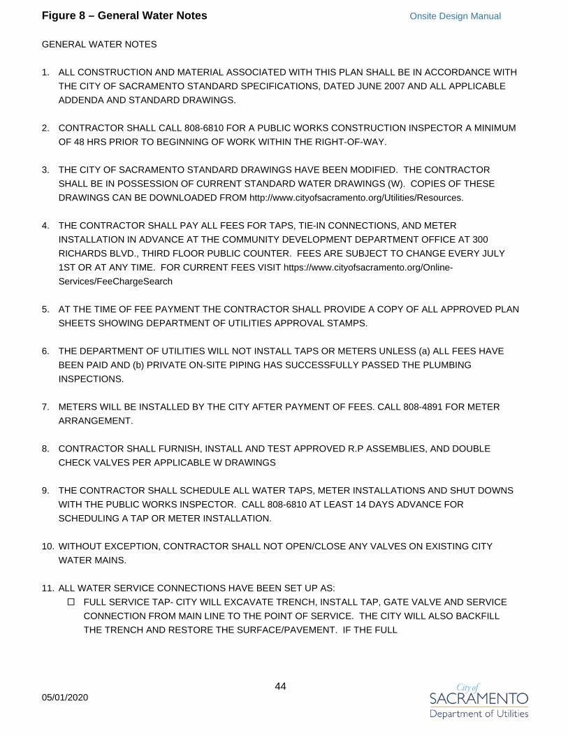
44 05/01/2020
Figure 8 – General Water Notes Onsite Design Manual
GENERAL WATER NOTES
1. ALL CONSTRUCTION AND MATERIAL ASSOCIATED WITH THIS PLAN SHALL BE IN ACCORDANCE WITHTHE CITY OF SACRAMENTO STANDARD SPECIFICATIONS, DATED JUNE 2007 AND ALL APPLICABLEADDENDA AND STANDARD DRAWINGS.
2. CONTRACTOR SHALL CALL 808-6810 FOR A PUBLIC WORKS CONSTRUCTION INSPECTOR A MINIMUMOF 48 HRS PRIOR TO BEGINNING OF WORK WITHIN THE RIGHT-OF-WAY.
3. THE CITY OF SACRAMENTO STANDARD DRAWINGS HAVE BEEN MODIFIED. THE CONTRACTORSHALL BE IN POSSESSION OF CURRENT STANDARD WATER DRAWINGS (W). COPIES OF THESEDRAWINGS CAN BE DOWNLOADED FROM http://www.cityofsacramento.org/Utilities/Resources.
4. THE CONTRACTOR SHALL PAY ALL FEES FOR TAPS, TIE-IN CONNECTIONS, AND METERINSTALLATION IN ADVANCE AT THE COMMUNITY DEVELOPMENT DEPARTMENT OFFICE AT 300RICHARDS BLVD., THIRD FLOOR PUBLIC COUNTER. FEES ARE SUBJECT TO CHANGE EVERY JULY1ST OR AT ANY TIME. FOR CURRENT FEES VISIT https://www.cityofsacramento.org/Online-Services/FeeChargeSearch
5. AT THE TIME OF FEE PAYMENT THE CONTRACTOR SHALL PROVIDE A COPY OF ALL APPROVED PLANSHEETS SHOWING DEPARTMENT OF UTILITIES APPROVAL STAMPS.
6. THE DEPARTMENT OF UTILITIES WILL NOT INSTALL TAPS OR METERS UNLESS (a) ALL FEES HAVEBEEN PAID AND (b) PRIVATE ON-SITE PIPING HAS SUCCESSFULLY PASSED THE PLUMBINGINSPECTIONS.
7. METERS WILL BE INSTALLED BY THE CITY AFTER PAYMENT OF FEES. CALL 808-4891 FOR METERARRANGEMENT.
8. CONTRACTOR SHALL FURNISH, INSTALL AND TEST APPROVED R.P ASSEMBLIES, AND DOUBLECHECK VALVES PER APPLICABLE W DRAWINGS
9. THE CONTRACTOR SHALL SCHEDULE ALL WATER TAPS, METER INSTALLATIONS AND SHUT DOWNSWITH THE PUBLIC WORKS INSPECTOR. CALL 808-6810 AT LEAST 14 DAYS ADVANCE FORSCHEDULING A TAP OR METER INSTALLATION.
10. WITHOUT EXCEPTION, CONTRACTOR SHALL NOT OPEN/CLOSE ANY VALVES ON EXISTING CITYWATER MAINS.
11. ALL WATER SERVICE CONNECTIONS HAVE BEEN SET UP AS: FULL SERVICE TAP- CITY WILL EXCAVATE TRENCH, INSTALL TAP, GATE VALVE AND SERVICE
CONNECTION FROM MAIN LINE TO THE POINT OF SERVICE. THE CITY WILL ALSO BACKFILLTHE TRENCH AND RESTORE THE SURFACE/PAVEMENT. IF THE FULL

45 05/01/2020
Figure 8 – General Water Notes – Continued Onsite Design Manual
SERVICE IS FOR THE INSTALLATION OF A PUBLIC FIRE HYDRANT, THE FIRE HYDRANT ASSEMBLY IS INCLUDED.
EASEMENT TAP (4" AND LARGER SERVICE) - THE CONTRACTOR SHALL PROVIDE EXCAVATIONAND EXPOSE THE MAIN LINE FOR THE CITY CREW TO INSTALL A TAP AND A GATE VALVE ONLY.CONTRACTOR IS REQUIRED TO INSTALL SERVICE CONNECTION FROM THE GATE VALVE TOTHE POINT OF SERVICE AND ALL NECESSARY APPURTENANCES. THE CONTRACTOR ALSO ISREQUIRED TO BACKFILL THE TRENCH AND RESTORE THE SURFACE /PAVEMENT.
EASEMENT TAP (2" AND SMALLER SERVICE) - THE CONTRACTOR SHALL PROVIDE EXCAVATIONAND EXPOSE THE MAIN LINE FOR THE CITY CREW TO INSTALL A TAP, A CORPORATION STOPAND A SERVICE CONNECTION. CONTRACTOR SHALL BACKFILL THE TRENCH AND RESTORETHE SURFACE/PAVEMENT.
12. IF CONSTRUCTION WATER IS NEEDED, THE CONTRACTOR MAY REQUEST FOR A TEMPORARYPUBLIC FIRE HYDRANT USE PERMIT. CALL 808-5454.

46 05/01/2020
Figure 9 – Erosion and Sediment Control Notes Onsite Design Manual
CITY OF SACRAMENTO STANDARD EROSION AND SEDIMENT CONTROL NOTES
1. THE CONTRACTOR SHALL FOLLOW THE GUIDELINES FOR THE CITY OF SACRAMENTO'S"ADMINISTRATIVE AND TECHNICAL PROCEDURES MANUAL FOR GRADING AND EROSION ANDSEDIMENT CONTROL" FOR THE MEASURES SHOWN OR STATED ON THESE PLANS.
2. CONTRACTOR MUST ENSURE THAT THE CONSTRUCTION SITE IS PREPARED PRIOR TO THE ONSETOF ANY STORM. CONTRACTOR SHALL HAVE ALL EROSION AND SEDIMENT CONTROL MEASURES INPLACE FOR THE WINTER MONTHS PRIOR TO OCTOBER 1.
3. ALL EROSION AND SEDIMENT CONTROL MEASURES SHALL BE MAINTAINED UNTIL DISTURBEDAREAS ARE STABILIZED. CHANGES TO THIS EROSION AND SEDIMENT CONTROL PLAN SHALL BEMADE TO MEET FIELD CONDITIONS ONLY WITH THE APPROVAL OF OR AT THE DIRECTION OF AREPRESENTATIVE OF THE DEPARTMENT OF UTILITIES.
4. THIS PLAN MAY NOT COVER ALL THE SITUATIONS THAT ARISE DURING CONSTRUCTION DUE TOUNANTICIPATED FIELD CONDITIONS. VARIATIONS MAY BE MADE TO THE PLAN IN THE FIELDSUBJECT TO THE APPROVAL OF OR AT THE DIRECTION OF A REPRESENTATIVE OF THEDEPARTMENT OF UTILITIES.
5. ALL EROSION AND SEDIMENT CONTROL MEASURES SHALL BE CHECKED BEFORE AND AFTER ALLSTORMS TO ENSURE MEASURES ARE FUNCTIONING PROPERLY.
6. CONTRACTOR SHALL MAINTAIN A LOG AT THE SITE OF ALL INSPECTIONS OR MAINTENANCE OFBMPS, AS WELL AS, ANY CORRECTIVE CHANGES TO THE BMPS OR EROSION AND SEDIMENTCONTROL PLAN.
7. IN AREAS WHERE SOIL IS EXPOSED, PROMPT REPLANTING WITH NATIVE COMPATIBLE, DROUGHT-RESISTANT VEGETATION SHALL BE PERFORMED. NO AREAS WILL BE LEFT EXPOSED OVER THEWINTER SEASON.
8. THE CONTRACTOR SHALL INSTALL THE STABILIZED CONSTRUCTION ENTRANCE PRIOR TOCOMMENCEMENT OF GRADING. LOCATION OF THE ENTRANCE MAY BE ADJUSTED BY THECONTRACTOR TO FACILITATE GRADING OPERATIONS. ALL CONSTRUCTION TRAFFIC ENTERING THEPAVED ROAD MUST CROSS THE STABILIZED CONSTRUCTION ENTRANCE. THE STABILIZEDCONSTRUCTION ENTRANCE SHALL REMAIN IN PLACE UNTIL THE ROAD BASE ROCK COURSE ISCOMPLETED.
9. ALL SEDIMENT DEPOSITED ON PAVED ROADWAYS SHALL BE SWEPT AT THE END OF EACHWORKING DAY OR AS NECESSARY.
10. CONTRACTOR SHALL PLACE ____________ AROUND ALL NEW DRAINAGE STRUCTURE OPENINGSIMMEDIATELY AFTER THE STRUCTURE OPENING IS CONSTRUCTED. THESE

47 05/01/2020
Figure 9 – Erosion and Sediment Control Notes – Continued Onsite Design Manual
____________ SHALL BE MAINTAINED AND REMAIN IN PLACE UNTIL CONSTRUCTION IS COMPLETED.
11. CONTRACTOR SHALL IMPLEMENT HOUSEKEEPING PRACTICES AS FOLLOWS:A. SOLID WASTE MANAGEMENT:
PROVIDE DESIGNATED WASTE COLLECTION AREAS AND CONTAINERS. ARRANGE FOR REGULARREMOVAL AND DISPOSAL. CLEAR SITE OF TRASH INCLUDING ORGANIC DEBRIS, PACKAGINGMATERIALS, SCRAP OR SURPLUS BUILDING MATERIALS AND DOMESTIC WASTE DAILY.
B. MATERIAL DELIVERY AND STORAGE:PROVIDE A DESIGNATED MATERIAL STORAGE AREA WITH SECONDARY CONTAINMENT SUCH ASBERMING. STORE MATERIAL ON PALLETS AND PROVIDE COVERING FOR SOLUBLE MATERIALS.RELOCATE STORAGE AREA INTO BUILDING SHELL WHEN POSSIBLE. INSPECT AREA WEEKLY.
C. CONCRETE WASTE:PROVIDE A DESIGNATED AREA FOR A TEMPORARY PIT TO BE USED FOR CONCRETE TRUCKWASH-OUT. DISPOSE OF HARDENED CONCRETE OFFSITE. AT NO TIME SHALL A CONCRETETRUCK DUMP ITS WASTE AND CLEAN ITS TRUCK INTO THE CITY STORM DRAINS VIA CURB ANDGUTTER. INSPECT DAILY TO CONTROL RUNOFF, AND WEEKLY FOR REMOVAL OF HARDENEDCONCRETE.
D. PAINT AND PAINTING SUPPLIES:PROVIDE INSTRUCTION TO EMPLOYEES AND SUBCONTRACTORS REGARDING REDUCTION OFPOLLUTANTS INCLUDING MATERIAL STORAGE, USE, AND CLEAN UP. INSPECT SITE WEEKLY FOREVIDENCE OF IMPROPER DISPOSAL.
E. VEHICLE FUELING, MAINTENANCE AND CLEANING:PROVIDE A DESIGNATED FUELING AREA WITH SECONDARY CONTAINMENT SUCH AS BERMING.DO NOT ALLOW MOBILE FUELING OF EQUIPMENT. PROVIDE EQUIPMENT WITH DRIP PANS.RESTRICT ONSITE MAINTENANCE AND CLEANING OF EQUIPMENT TO A MINIMUM. INSPECT AREAWEEKLY.
F. HAZARDOUS WASTE MANAGEMENT:PREVENT THE DISCHARGE OF POLLUTANTS FROM HAZARDOUS WASTES TO THE DRAINAGESYSTEM THROUGH PROPER MATERIAL USE, WASTE DISPOSAL AND TRAINING OF EMPLOYEES.HAZARDOUS WASTE PRODUCTS COMMONLY FOUND ON-SITE INCLUDE BUT ARE NOT LIMITEDTO PAINTS & SOLVENTS, PETROLEUM PRODUCTS, FERTILIZERS, HERBICIDES & PESTICIDES,SOIL STABILIZATION PRODUCTS, ASPHALT PRODUCTS AND CONCRETE CURING PRODUCTS.

48 05/01/2020
Figure 10 – Onsite Project Storage Onsite Design Manual
Basin Nominal Capacity CFS/AC
Storage per Acre of Increased Imperviousness (Cubic Feet) Basin
Nominal Capacity CFS/AC
Storage per Acre of Increased Imperviousness (Cubic Feet)
100-Year 10-Year 100-Year 10-Year5 0.2 7,000 3,600 60 UP NA NA 7 UP NA NA 61 NN4 4,300 2,200 8 0.2 7,000 3,600 62 NN 10,600 5,500
10 0.15 8,500 4,300 63 0.07 12,000 6,600 11 NN 10,600 5,500 64 NN4 4,300 2,200 12 NN 10,600 5,500 65 0.07 12,000 6,600 13 NN 10,600 5,500 66 0.27 5,600 2,900 14 NN 10,600 5,500 67 0.12 9,700 4,950 15 NN 10,600 5,500 68 0.15 8,600 4,300 16 NN 10,600 5,500 69 0.11 10,200 5,200 17 NN 10,600 5,500 70 0.1 10,600 5,500 18 NN 10,600 5,500 71 0.12 9,700 4,950 19 0.2 7,000 3,600 73 UP NA NA 20 NN4 4,300 2,150 83 UP NA NA 22 0.11 10,200 5,200 89 0.1 10,600 5,500 23 0.12 9,700 4,950 91 0.17 7,900 3,950 24 0.08 11,600 6,200 94 0.13 9,300 4,700 25 0.12 9,700 4,950 95 0.29 5,400 2,750 26 0.11 10,200 5,200 96 0.2 7,000 3,600 27 0.13 9,300 4,700 97 0.2 7,000 3,600 28 0.12 9,700 4,950 98 0.19 7,300 3,700 30 0.12 9,700 4,950 99 0.3 5,300 2,700 31 0.16 8,200 4,100 101 0.19 7,300 3,700 33 0.1 10,600 5,500 102 0.18 7,600 3,800 34 0.12 9,700 4,950 103 0.15 8,600 4,300 35 0.8 3,350 1,850 104 0.3 5,300 2,700 37 0.24 6,100 3,150 108 0.09 11,000 5,800 38 UP NA NA 109 0.18 7,600 3,800 39 0.13 9,300 4,700 110 0.07 12,000 6,600 41 0.07 12,000 6,600 111 0.3 5,300 2,700 43 0.1 10,600 5,500 112 0.3 5,300 2,700 44 0.23 6,300 3,250 113 UP NA NA 46 0.22 6,500 3,350 114 0.22 6,500 3,350 47 0.17 7,900 3,950 115 0.24 6,100 3,150 50 0.15 8,600 4,300 116 0.2 7,000 3,600 51 0.15 8,600 4,300 117 0.2 7,000 3,600 52 0.22 6,500 3,350 128 0.18 7,600 3,800 54 0.14 8,900 4,450 129 0.3 5,300 2,700 56 0 15,000 10,500 130 0.28 5,500 2,800 58 0.27 5,600 2,800 132 0.3 5,300 2,700
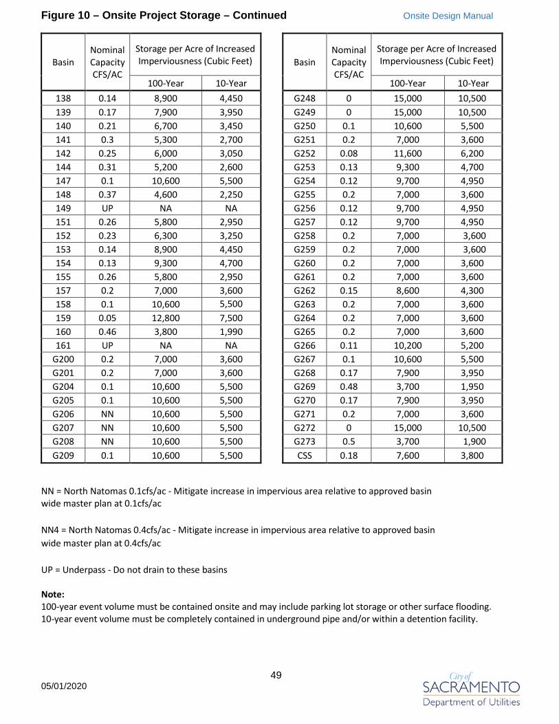
49 05/01/2020
Figure 10 – Onsite Project Storage – Continued Onsite Design Manual
Basin Nominal Capacity CFS/AC
Storage per Acre of Increased Imperviousness (Cubic Feet) Basin
Nominal Capacity CFS/AC
Storage per Acre of Increased Imperviousness (Cubic Feet)
100-Year 10-Year 100-Year 10-Year138 0.14 8,900 4,450 G248 0 15,000 10,500 139 0.17 7,900 3,950 G249 0 15,000 10,500 140 0.21 6,700 3,450 G250 0.1 10,600 5,500 141 0.3 5,300 2,700 G251 0.2 7,000 3,600 142 0.25 6,000 3,050 G252 0.08 11,600 6,200 144 0.31 5,200 2,600 G253 0.13 9,300 4,700 147 0.1 10,600 5,500 G254 0.12 9,700 4,950 148 0.37 4,600 2,250 G255 0.2 7,000 3,600 149 UP NA NA G256 0.12 9,700 4,950 151 0.26 5,800 2,950 G257 0.12 9,700 4,950 152 0.23 6,300 3,250 G258 0.2 7,000 3,600 153 0.14 8,900 4,450 G259 0.2 7,000 3,600 154 0.13 9,300 4,700 G260 0.2 7,000 3,600 155 0.26 5,800 2,950 G261 0.2 7,000 3,600 157 0.2 7,000 3,600 G262 0.15 8,600 4,300 158 0.1 10,600 5,500
G263 0.2 7,000 3,600
159 0.05 12,800 7,500 G264 0.2 7,000 3,600 160 0.46 3,800 1,990 G265 0.2 7,000 3,600 161 UP NA NA G266 0.11 10,200 5,200
G200 0.2 7,000 3,600 G267 0.1 10,600 5,500 G201 0.2 7,000 3,600 G268 0.17 7,900 3,950 G204 0.1 10,600 5,500 G269 0.48 3,700 1,950 G205 0.1 10,600 5,500 G270 0.17 7,900 3,950 G206 NN 10,600 5,500 G271 0.2 7,000 3,600 G207 NN 10,600 5,500 G272 0 15,000 10,500 G208 NN 10,600 5,500 G273 0.5 3,700 1,900 G209 0.1 10,600 5,500 CSS 0.18 7,600 3,800
NN = North Natomas 0.1cfs/ac - Mitigate increase in impervious area relative to approved basin wide master plan at 0.1cfs/ac
NN4 = North Natomas 0.4cfs/ac - Mitigate increase in impervious area relative to approved basin wide master plan at 0.4cfs/ac
UP = Underpass - Do not drain to these basins
Note: 100-year event volume must be contained onsite and may include parking lot storage or other surface flooding.10-year event volume must be completely contained in underground pipe and/or within a detention facility.

50 05/01/2020
Figure 10 – Onsite Project Storage – Continued Onsite Design Manual
0
1,000
2,000
3,000
4,000
5,000
6,000
7,000
8,000
9,000
10,000
11,000
12,000
13,000
14,000
15,000
16,000
0 0.05 0.1 0.15 0.2 0.25 0.3 0.35 0.4 0.45 0.5
Cubi
c Fe
et o
f Sto
rage
per
Acr
e of
Impe
rvio
usne
ss
Nominal Capacity of Sump (CFS/AC)
Onsite Project Storage Graph
10-Year Event
100-Year Event