TROLL 9500 Multiparameter Water Quality Monitoring Instrument

Onion Creek Recharge Project
Quality Assurance Project Plan
Barton Springs/Edwards Aquifer
Conservation District
Austin, Texas 78748
Effective Period: September 12, 2012 – September 12, 2013
Questions concerning this quality assurance project plan should be directed to:
Brian A. Smith
Barton Springs/ Edwards Aquifer Conservation District
Aquifer Science Team Leader
1124 Regal Row
Austin, TX 78748
512-282-8441

1
This page intentionally left blank

Quality Assurance Project Plan
Onion Creek Recharge Project August 29, 2012
2

Quality Assurance Project Plan
Onion Creek Recharge Project August 29, 2012
3
A2 Table of Contents
A1 Approval Sheets ...................................................................................................................................... 2
A2 Table of Contents .................................................................................................................................... 3
A3 Distribution List ...................................................................................................................................... 4
List of Acronyms .......................................................................................................................................... 5
A4 Project/Task Organization ....................................................................................................................... 7
Figure A4.1 - Organization Chart .................................................................................................... 9
A5 Problem Definition/Background ........................................................................................................... 10
A6 Project/Task Description ...................................................................................................................... 11
A7 Quality Objectives and Criteria ............................................................................................................. 12
Table A7.1 Measurement Performance Specifications for Continuous Instream Monitoring and
Stormwater Monitoring ..................................................................................................... 13
Table A7.2 DQOs for Continuous Water-Quality Monitoring Sondes (Multi-Probes) ................. 14
Table A7.3 MQOs for 500 KHz Acoustic Doppler Current Profiler (ADCP) Flow Meters ......... 14
A8 Special Training/Certification ............................................................................................................... 17
A9 Documents and Records ........................................................................................................................ 18
B1 Sampling Process Design (Experimental Design) ................................................................................. 21
Table B1.1 Monitoring Sites .......................................................................................................... 23
B2 Sampling Methods ................................................................................................................................. 24
Table B2.1 Methods and Equipment for Continuous Water-Quality Monitoring ......................... 25
Table B2.2 Stormwater Monitoring ............................................................................................... 25
B3 Sampling Handling and Custody ........................................................................................................... 27
B4 Analytical Methods ............................................................................................................................... 29
B5 Quality Control ...................................................................................................................................... 31
B6 Instrument/Equipment Testing, Inspection and Maintenance ............................................................... 35
B7 Instrument/Equipment Calibration and Frequency ............................................................................... 35
B8 Inspection/Acceptance of Supplies and Consumables .......................................................................... 36
B9 Non-direct Measurement ....................................................................................................................... 37
B10 Data Management ............................................................................................................................... 37
Table B10.1 SWQMIS Parameters ................................................................................................ 39
C1 Assessments and Response Actions ...................................................................................................... 41
Table C1.1 Assessments and Response Actions ............................................................................ 43
C2 Reports to Management ........................................................................................................................ 44
D1 Data Review, Verification, and Validation ........................................................................................... 44
D2 Verification and Validation Methods .................................................................................................... 45
D3 Reconciliation with User Requirements ................................................................................................ 45
Appendix A. Area Location Map ................................................................................................................ 46
Appendix B. Data Summary ....................................................................................................................... 48
Appendix C. Manufacturer’s Operator Manuals ......................................................................................... 50
Appendix D. Field Data Reporting Form .................................................................................................... 53
Appendix E. Chain-of-Custody Form ......................................................................................................... 55
Appendix F. Automated Sampler Testing with Maintenance and Calibration Requirements .................... 57
Appendix G. Standard Operating Procedures for the In-Situ Troll 9500 SOP BSEACD-001 ................... 59

Quality Assurance Project Plan
Onion Creek Recharge Project August 29, 2012
4
A3 Distribution List
BSEACD will provide copies of this project plan, and any amendments or revisions of this plan, to each
project participant defined in the list below. BSEACD will document receipt of the plan by each
participant and maintain this documentation as part of the project’s quality assurance records. This
documentation will be available for review.
Texas Commission on Environmental Quality
P.O. Box 13087
Austin, Texas 78711-3087
Chuck Dvorsky, CWQMN Network Coordinator
(512) 239-5550
Barton Springs/Edwards Aquifer Conservation District
1124 Regal Row
Austin, TX 78748
Brian A. Smith, Project Manager
(512) 282-8441
Brian Hunt, Quality Assurance Officer
(512) 282-8441
LCRA Environmental Laboratory Services
3505 Montopolis
Austin, TX 78744
Alicia Gill, Laboratory Manager
(512) 356-6022
Hollis Pantalion, Laboratory Quality Assurance Officer
(512) 356-6022

Quality Assurance Project Plan
Onion Creek Recharge Project August 29, 2012
5
List of Acronyms
AWRL Ambient Water Reporting Limit
BMP Best Management Practice
BSEACD Barton Springs/Edwards Aquifer Conservation District
CAMS Continuous Ambient Monitoring Station
CAR Corrective Action Report
COC Chain of Custody
CRP Clean Rivers Program
CVS Calibration Verification Sample
CWA Clean Water Act
CWQMN Continuous Water Quality Monitoring Network
DOC Demonstration of Capability
DMP Data Management Plan
DMRG Data Management Reference Guide
DQO Data Quality Objective
EPA Environmental Protection Agency
GIS Geographic Information System
LCS Laboratory Control Sample (formerly Laboratory Control
Standard)
LCSD Laboratory Control Sample Duplicate (formerly Laboratory
Control Standard Duplicate)
LOD Limit of Detection
LOQ Limit of Quantitation (formerly reporting limit)
MOM Manufacturer’s Operator Manuals
NCR Nonconformance Report
NELAC National Environmental Laboratory Accreditation Conference
NPDES National Pollutant Discharge Elimination System
NPS Nonpoint Source
NTU Nephelometric Turbidity Units
PO Project Officer
QA/QC Quality Assurance/Quality Control
QAM Quality Assurance Manual
QAO Quality Assurance Officer
QAPP Quality Assurance Project Plan

Quality Assurance Project Plan
Onion Creek Recharge Project August 29, 2012
6
QAS Quality Assurance Specialist
QMP Quality Management Plan
RPD Relative Percent Difference
SLOC Station Location Form
SOP Standard Operating Procedure
SWQM Surface Water Quality Monitoring
SWQMIS Surface Water Quality Monitoring Information System
TCEQ Texas Commission on Environmental Quality
TSS Total Suspended Solids
TSWQS Texas Surface Water Quality Standards
WQI Water Quality Inventory

Quality Assurance Project Plan
Onion Creek Recharge Project August 29, 2012
7
A4 Project/Task Organization
TCEQ
Water Quality Planning Division
Chuck Dvorsky
CWQMN Network Coordinator
Responsible for management and oversight of the TCEQ CWQMN Program. Oversees the development
of QA guidance for the CWQMN program to be sure it is within pertinent frameworks of the TCEQ.
Monitors the effectiveness of the program quality system. Reviews and approves all CWQMN projects,
internal QA audits, corrective actions, reports, work plans, and contracts. Enforces corrective action, as
required. Ensures CWQMN personnel are fully trained and adequately staffed.
Barton Springs/Edwards Aquifer Conservation District (BSEACD)
Brian Smith
BSEACD Project Manager Responsible for ensuring tasks and other requirements in the contract are executed on time and are of
acceptable quality. Monitors and assesses the quality of work. Coordinates attendance at conference calls,
training, meetings, and related project activities with the TCEQ. Responsible for verifying the QAPP is
followed and the project is producing data of known and acceptable quality. Ensures adequate training
and supervision of all monitoring and data collection activities. Complies with corrective action
requirements.
Brian Hunt
BSEACD QAO Responsible for coordinating development and implementation of the QA program. Responsible for
writing and maintaining the QAPP. Responsible for maintaining records of QAPP distribution, including
appendices and amendments. Responsible for maintaining written records of sub-tier commitment to
requirements specified in this QAPP. Responsible for identifying, receiving, and maintaining project
quality assurance records. Responsible for coordinating with the TCEQ QAS to resolve QA- related
issues. Notifies the BSEACD Project Manager and TCEQ Project Manager of particular circumstances
which may adversely affect the quality of data. Responsible for validation and verification of all data
collected according to Section D2 procedures and acquired data procedures after each task is performed.
Coordinates the research and review of technical QA material and data related to water quality monitoring
system design and analytical techniques. Conducts laboratory inspections. Develops, facilitates, and
conducts monitoring systems audits.
Kendall Bell-Enders
BSEACD Data Manager Responsible for the acquisition, verification, and transfer of data to the TCEQ. Oversees data
management for the study. Performs data quality assurances prior to transfer of data to TCEQ.
Responsible for transferring data to the TCEQ in the acceptable format. Ensures data are submitted
according to workplan specifications. Provides the point of contact for the TCEQ Data Manager to
resolve issues related to the data.

Quality Assurance Project Plan
Onion Creek Recharge Project August 29, 2012
8
Brian Hunt
BSEACD Field Supervisor Responsible for supervising all aspects of the sampling and measurement of surface waters and other
parameters in the field. Responsible for the acquisition of water samples and field data measurements in a
timely manner that meet the quality objectives specified in Section A7 (Table A7.1), as well as the
requirements of Sections B1 through B8. Responsible for field scheduling, staffing, and ensuring that
staff is appropriately trained as specified in Sections A6 and A8.
LCRA Environmental Laboratory Services
Alicia Gill Laboratory Manager
Responsible for supervision of laboratory personnel involved in generating analytical data for this project.
Responsible for ensuring that laboratory personnel involved in generating analytical data have adequate
training and a thorough knowledge of the QAPP and all SOPs specific to the analyses or task performed
and/or supervised. Responsible for oversight of all operations, ensuring that all QA/QC requirements are
met, and documentation related to the analysis is completely and accurately reported. Enforces corrective
actions, as required. Develops and facilitates monitoring systems audits.
Hollis Pantalion
Laboratory QAO Monitors the implementation of the QAM and the QAPP within the laboratory to ensure complete
compliance with QA objectives as defined by the contract and in the QAPP. Conducts internal audits to
identify potential problems and ensure compliance with written SOPs. Responsible for supervising and
verifying all aspects of the QA/QC in the laboratory. Performs validation and verification of data before
the report is sent to BSEACD. Insures that all QA reviews are conducted in a timely manner from real-
time review at the bench during analysis to final pass-off of data to the QA officer.

Quality Assurance Project Plan
Onion Creek Recharge Project August 29, 2012
9
Figure A4.1. Organization Chart - Lines of Communication
Brian Smith BSEACD
Project Manager
Alicia Gill Laboratory
Manager
Kendall Bell-Enders
Field Sampling
Staff
Kendal Bell-
Enders
Data Manager
Brian Hunt
QAO
Hollis Pantalion Laboratory
QAO
Chuck Dvorsky
TCEQ CWQMN
Network Coordinator
TCEQ Data
Manager
Lines of Management
Lines of Communication

Quality Assurance Project Plan
Onion Creek Recharge Project August 29, 2012
10
A5 Problem Definition/Background
The Edwards Aquifer, located in south-central Texas, is one of the most prolific karst aquifers in the
United States and is an important groundwater resource for municipal, industrial, domestic, agricultural,
recreational, and ecological needs. The aquifer extends about 270 miles from the Rio Grande River along
the Mexico/United States border at Del Rio, east to San Antonio, then northeast through Austin to Salado.
Hydrologic divides separate the Edwards Aquifer into three major segments: the San Antonio, Barton
Springs, and Northern segments and numerous subsections.
The Barton Springs segment of the Edwards Aquifer is the focus of this project (Appendix A, Location
Map). Approximately 60,000 people depend on water from the Barton Springs aquifer as their sole source
of drinking water, and the various spring outlets at Barton Springs are the only known habitats for the
endangered Barton Springs salamander.
Up to 85 percent of recharge to the aquifer is derived from streams originating on the contributing zone,
located up gradient and west of the recharge zone. Water flowing onto the recharge zone sinks into
numerous caves, sinkholes, and fractures recharging the aquifer. Groundwater then moves northeast
toward wells and Barton Springs. Onion Creek contributes about one third of all recharge, with most of
that recharge occurring within several discrete recharge features within the creek bottom (Appendix A).
EPA identifies karst aquifers as one of the most vulnerable to pollution because of their rapid
groundwater velocities and limited ability to filter contaminants. Numerous tracer tests have been
performed on the Barton Springs aquifer demonstrating that rapid groundwater flow occurs in an
integrated network of conduits discharging at wells and springs. A portion of this groundwater flows from
the conduits into the diffuse matrix of the aquifer building up storage in the aquifer. Water from storage
flows diffusely to wells or back into the conduit network. This dual flow system results in the potential
for contamination to rapidly impact wells and springs, as well as slowly accumulate and move within the
matrix of the aquifer.
The TCEQ lists the Barton Springs aquifer on a list of impaired groundwater resources. Onion Creek is
listed on the 303(d) list of impaired streams. Increases in sediment, bacteria, and other contaminants in
groundwater as a result of storm-flow events in the Barton Springs aquifer have been documented by
analysis of water samples from monitor and water-supply wells.
To reduce the amount of sediment and other storm-related contaminants entering one of these recharge
features, an automated control system has been designed and installed at the BMP that was previously
constructed over Antioch Cave on Onion Creek. Two valves on the BMP controls flow into the cave.
During periods of storm water flow in the creek, valves will be closed to prevent entry of sediment-laden
water into the recharge feature. Continuous water quality monitoring network (CWQMN) systems have
been installed at the Antioch site and at the low water dam site within the Onion Creek Management
Area, which will monitor turbidity and other parameters in water flowing in the creek. When turbidity
reaches a level indicative of storm-water flow, 100 Nephelometric Turbidity Units (NTU), the valve on
the Antioch BMP will be automatically closed. When turbidity drops to a level consistent with no storm-
water flow, 50 NTU, the valve will be opened, allowing better quality water to enter the aquifer.
Operation of these systems will decrease the amount of sediment and other storm-water related
contaminants entering the aquifer. This will improve the quality of water in the aquifer that thousands of
users rely upon and that the endangered salamanders need for survival.

Quality Assurance Project Plan
Onion Creek Recharge Project August 29, 2012
11
To monitor the influence of recharge via Antioch Cave on the Edwards Aquifer, a multiport monitor well
was installed near Antioch Cave as part of the 319h grant project. The movement of non-point source
pollution in the various units of the Edwards Aquifer will be monitored in this well when recharge from
Onion Creek is taking place in Antioch Cave.
A6 Project/Task Description
CWQMN Sites
The two CWQMN systems installed in the Onion Creek watershed monitor water quality at two locations,
one in the upper portion of the recharge zone, and the second at the lower portion of the recharge zone
within the Barton Springs segment of the Edwards Aquifer (Barton Springs aquifer).
This project’s goal is to improve water quality in the Barton Springs aquifer by facilitating timely and
efficient responses to recharge events by continuously monitoring water quality in the Onion Creek
Watershed and excluding “first flush” flows of contaminated storm water into a recharge feature on
Onion Creek. This is accomplished using a BMP with a valve that automatically opens when a storm
water pulse has passed to allow recharge of clean surface water into the aquifer. The valve is triggered
based on CWQMN data from the site. The valve closes when turbidity is determined to be high, currently
at 100 NTU. The valve reopens when turbidity lowers to acceptable concentrations of 50 NTU.
Two CWQMN sites have been installed on Onion Creek, one at the Antioch BMP location and the second
8 miles upstream of Antioch at the Onion Creek Management Area low water dam. Each CWQMN site
in the Onion Creek Watershed analyzes ambient water for DO, turbidity, temperature, and conductivity.
Continuous water-quality monitoring is conducted in accordance with TCEQ’s established CWQMN
quality assurance project plan (QAPP). Data are transmitted to TCEQ electronically and uploaded into
the LEADS system.
Surface Water Sampling
Water samples from the Antioch BMP on Onion Creek are collected by using an automatic sampler
during occasional storm flow events. Manual (grab) samples are collected when possible for base flow
samples between storm events.
Samples are analyzed for TSS, TDS, turbidity, nitrate and nitrite as N, and total phosphate. An automated
sampler collects samples when triggered by a storm event. Water-quality data are used to determine the
amount of pollutant loads (nitrate/nitrite, phosphorus, and sediment) that are prevented from entering the
aquifer by operation of the Antioch BMP. This is accomplished by first calculating the amount of
contaminants in Onion Creek during the storm pulse and then calculating the amount of water not
entering the aquifer when the valve is closed. This volume is determined by taking the flow rate of water
entering the BMP when the valve is first opened following a storm event multiplied by the length of time
the valve was closed. The masses of nitrate/nitrite, phosphorous, and sediment prevented from entering
the aquifer are calculated with the following formula:

Quality Assurance Project Plan
Onion Creek Recharge Project August 29, 2012
12
Q * CN,P,S * T = MN,P,S
where
Q = Rate of flow into Antioch BMP when valve is first opened following storm pulse
CN,P,S = Concentration of N (nitrate/nitrite), P (phosphorous), or S (sediment) during storm pulse
T = Duration of time that valve on BMP was closed
MN,P,S = Mass of contaminant prevented from entering aquifer
See Section B1 for monitoring to be conducted under this QAPP.
Revisions to the QAPP
Until the work described is completed, this QAPP shall be revised as necessary and reissued annually on
the anniversary date, or revised and reissued within 120 days of significant changes, whichever is sooner.
The most recently approved QAPPs shall remain in effect until revisions have been fully approved;
reissuances (i.e., annual updates) must be submitted to the TCEQ for approval before the last version has
expired. If the entire QAPP is current, valid, and accurately reflects the project goals and organization’s
policy, the annual reissuance may be done by a certification that the plan is current. This can be
accomplished by submitting a cover letter stating the status of the QAPP and a copy of new, signed
approval pages for the QAPP.
Amendments
Amendments to the QAPP may be necessary to reflect changes in project organization, tasks, schedules,
objectives, and methods; address deficiencies and nonconformances; improve operational efficiency;
and/or accommodate unique or unanticipated circumstances. Requests for amendments are directed from
the BSEACD Project Manager to the TCEQ Project Manager in writing using the QAPP Amendment
shell. The changes are effective immediately upon approval by the TCEQ NPS Project Manager and
Quality Assurance Specialist, or their designees, and the EPA Project Officer.
Amendments to the QAPP and the reasons for the changes will be documented, and revised pages will be
forwarded to all persons on the QAPP distribution list by the BSEACD QAO. Amendments shall be
reviewed, approved, and incorporated into a revised QAPP during the annual revision process or within
120 days of the initial approval in cases of significant changes.
A7 Quality Objectives and Criteria
The objectives of the data collection efforts of this project are as follows:
Continuous water quality monitoring is conducted to operate a valve over a recharge feature for the
Barton Springs segment of the Edwards Aquifer. Continuous water quality monitoring also obtains
information about water quality in Onion Creek and water quality entering the aquifer. CWQMN data are
telemetered to TCEQ and uploaded into the LEADS system.

Quality Assurance Project Plan
Onion Creek Recharge Project August 29, 2012
13
Data from automatic samplers are used to calculate the pollutant loads associated with stormwater runoff
events in Onion Creek.
Manual grab samples are collected to determine the amount of sediment and contaminants that enter the
aquifer through Antioch Cave when the valve is open. These values will be compared to values for storm
flow when the valve on the Antioch BMP is closed. Such a comparison gives us a better understanding of
the quality of water entering the aquifer along Onion Creek. With that knowledge, we can better
understand non-point source pollution in the Onion Creek watershed. Grab samples, that are
representative of base flow conditions, are collected following occasional sampled storm events. These
sampling events occur only when BSEACD staff and resources are available.
The Onion Creek Recharge Project employs only methods and techniques which have been determined to
produce measurement data of a known and verifiable quality and which are sufficient to meet the
objectives of the project.
Measurement Quality Objectives (MQOs) and Data Quality Objectives (DQOs) to support the
Continuous Water Quality Monitoring Network (CWQMN) objectives are specified in Tables A7.2 and
A7.3, respectively. Data Quality Objectives for automatic sampling data are in table A7.1. The quality
control (QC) program has been developed with these objectives in mind. Methods used for water-quality
measurements in the CWQMN are based on Standard Methods used for the Examination of Water and
Wastewater, 20th Edition, 1998 unless otherwise specified.
Table A7.1 Measurement Performance Specifications for Automatic and Manual (Grab Sample)
Monitoring
PARAMETER
UNITS
MATRIX
METHOD
PARAMETER
CODE
AWRL
Limit of
Quantitation
(LOQ)
Recovery
at LOQ
(%)
PRECISION
(RPD of
LCS/LCSD)
BIAS
%Rec.
of
LCS
Completeness
(%)
Field /
Lab
Specific
Conductivity
uS/cm water SM 2510B
and
TCEQ
SOP
00095 NA NA NA NA NA 90 Lab
Nitrate/Nitrite – N mg/l water SM4500
NO3-H
00630 .05 0.02 70-130 20 80-120 90 Lab
Total Phosphorus mg/L water EPA 365.4 00665 .06 0.02 70-130 20 80-120 90 Lab
TSS_SM mg/L water SM 2540
D
00530 4 1 NA
20 80-120 90 Lab
TDS_SM mg/l water SM 2540
C
70300
10 10 NA
20 80-120 90 Lab
TURB_W
Turbidity
NTU water SM 2130
B
82079 NA NA NA NA NA 90 Lab
References: US EPA Methods for Chemical Analysis of Water and Wastewater, Manual #EPA-600/4-79-020. American Public Health Association, American Water
Works Association and Water Environment Federation, Standard Methods for the Examination of Water and Waste Water, 20th Ed., Texas Commission on
Environmental Quality Surface Water Quality Monitoring Procedures, Volume 1.
** Based on range statistic as described in Standard Methods, 21st Edition, Section 9020-B, Quality Assurance/Quality Control –
Intralaboratory Quality Control Guidelines. This criterion applies to bacteriological duplicates with concentrations >10 MPN/100mL
or > 10 org./100 mL.

Quality Assurance Project Plan
Onion Creek Recharge Project August 29, 2012
14
Table A7.2 DQOs for Continuous Water-Quality Monitoring Sondes (Multi-Probes)
Parameter LEADS
Parameter Code
Units
Measurement
Equipment
Method Calibration Verification
Sample Acceptance Limit (CVS)
pH* 10400 pH /units In-Situ TROLL 9500 Glass electrode, Standard
Method 4500-H+B
± 0.50 pH unit*
DO* 10300 mg/L In-Situ TROLL 9500 Polarographic & Galvanic
membrane electrode, Standard Method 4500-O-G
% Saturation ≤ 6.0%*
± 0.50 mg/L*
DO* 10300 mg/L
In-Situ TROLL 9500
Optical (luminescence
quenching) ASTM D888-05
**
% Saturation ≤ 6.0%* ± 0.50 mg/L*
SC* 10095 µS/cm In-Situ TROLL 9500
Conductivity cell, Standard Method 2510B
5.0% RPE*
Temperature* 10010 C Thermistor Standard Method 2550 B ± 0.50 ºC*
Depth NA Feet @
30psi In-Situ TROLL 9500
NA NA
Turbidity 10104 NTU In-Situ TROLL 9500
EPA 170.1 ± 3.0 FNU/NTU or ± 5%
*Parameters and CVS acceptance criteria for use in the Clean Water Act 305(b) Inventory and 303(d) Lists per SWQM DQOs.
**Method not based on Standard Methods for the Examination of Water and Wastewater, 20th Edition, 1998. EPA Region 6 has approved Optical
DO methods for use in the CWQMN. ***LEADS reports turbidity measurements in NTUs.
ºC = degrees centigrade
NA = Not Applicable
Table A7.3 MQOs for 500 KHz Acoustic Doppler Current Profiler (ADCP) Flow Meters
1- vertical beam
2- water velocity
CFS = cubic feet per second
TBD = To be determined. This information will be provided in an amendment to the QAPP.
Precision Precision is the degree to which a set of observations or measurements of the same property, obtained
under similar conditions, conform to themselves. It is a measure of agreement among replicate
measurements of the same property, under prescribed similar conditions, and is an indication of random
error.
Field splits are used to assess the variability of sample handling, preservation, and storage, as well as the
analytical process, and are prepared by splitting samples in the field. Control limits for field splits are
defined in Section B5.
Laboratory precision is assessed by comparing replicate analyses of laboratory control samples in the
sample matrix (e.g. deionized water, sand, commercially available tissue). Precision results are compared
Parameter SOP Flow Meter Units Method Range1 Range2 Resolution Accuracy
Volumetric Flow
Rate
Water Velocity
00094 Shallow Water
(Intermittent Streams) CFS
Doppler
Ultrasonic,
frequency
500kHz
0.033 to 5.0 ft
-5 to 20 ft/s
+0.01 ft
+ 0.1 ft/s
TBD
Quality Assurance Project Plan
Onion Creek Recharge Project August 29, 2012
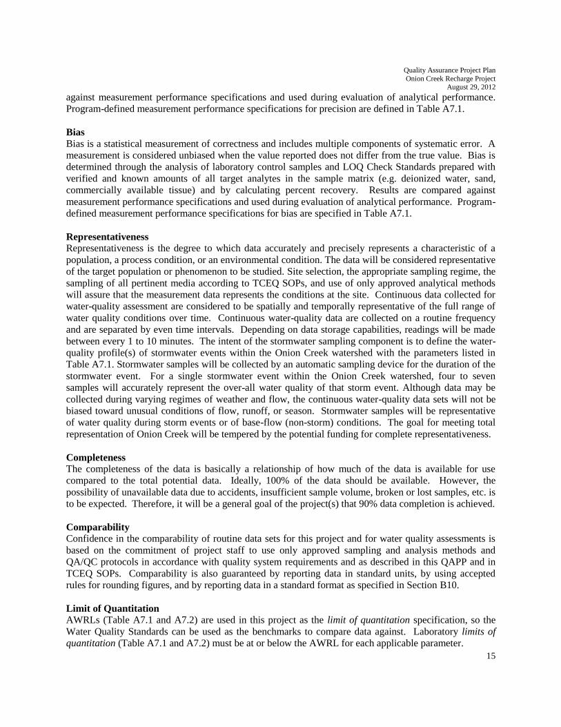
15
against measurement performance specifications and used during evaluation of analytical performance.
Program-defined measurement performance specifications for precision are defined in Table A7.1.
Bias Bias is a statistical measurement of correctness and includes multiple components of systematic error. A
measurement is considered unbiased when the value reported does not differ from the true value. Bias is
determined through the analysis of laboratory control samples and LOQ Check Standards prepared with
verified and known amounts of all target analytes in the sample matrix (e.g. deionized water, sand,
commercially available tissue) and by calculating percent recovery. Results are compared against
measurement performance specifications and used during evaluation of analytical performance. Program-
defined measurement performance specifications for bias are specified in Table A7.1.
Representativeness Representativeness is the degree to which data accurately and precisely represents a characteristic of a
population, a process condition, or an environmental condition. The data will be considered representative
of the target population or phenomenon to be studied. Site selection, the appropriate sampling regime, the
sampling of all pertinent media according to TCEQ SOPs, and use of only approved analytical methods
will assure that the measurement data represents the conditions at the site. Continuous data collected for
water-quality assessment are considered to be spatially and temporally representative of the full range of
water quality conditions over time. Continuous water-quality data are collected on a routine frequency
and are separated by even time intervals. Depending on data storage capabilities, readings will be made
between every 1 to 10 minutes. The intent of the stormwater sampling component is to define the water-
quality profile(s) of stormwater events within the Onion Creek watershed with the parameters listed in
Table A7.1. Stormwater samples will be collected by an automatic sampling device for the duration of the
stormwater event. For a single stormwater event within the Onion Creek watershed, four to seven
samples will accurately represent the over-all water quality of that storm event. Although data may be
collected during varying regimes of weather and flow, the continuous water-quality data sets will not be
biased toward unusual conditions of flow, runoff, or season. Stormwater samples will be representative
of water quality during storm events or of base-flow (non-storm) conditions. The goal for meeting total
representation of Onion Creek will be tempered by the potential funding for complete representativeness.
Completeness The completeness of the data is basically a relationship of how much of the data is available for use
compared to the total potential data. Ideally, 100% of the data should be available. However, the
possibility of unavailable data due to accidents, insufficient sample volume, broken or lost samples, etc. is
to be expected. Therefore, it will be a general goal of the project(s) that 90% data completion is achieved.
Comparability Confidence in the comparability of routine data sets for this project and for water quality assessments is
based on the commitment of project staff to use only approved sampling and analysis methods and
QA/QC protocols in accordance with quality system requirements and as described in this QAPP and in
TCEQ SOPs. Comparability is also guaranteed by reporting data in standard units, by using accepted
rules for rounding figures, and by reporting data in a standard format as specified in Section B10.
Limit of Quantitation AWRLs (Table A7.1 and A7.2) are used in this project as the limit of quantitation specification, so the
Water Quality Standards can be used as the benchmarks to compare data against. Laboratory limits of
quantitation (Table A7.1 and A7.2) must be at or below the AWRL for each applicable parameter.

Quality Assurance Project Plan
Onion Creek Recharge Project August 29, 2012
16
Laboratory Measurement Quality Control Requirements and Acceptability Criteria are provided in
Section B5.
Analytical Quantitation
To demonstrate the ability to recover at the limit of quantitation, the laboratory will analyze an LOQ
check standard on each day samples are run.
Laboratory Measurement Quality Control Requirements and Acceptability Criteria are provided in
Section B5.
DQOs for CWQMN
The MQOs and DQOs to support the CWQMN objectives are specified in Tables A7.2 and A7.3. The
DQOs for CWQMN DO, SC, pH, and temperature data that can be used in the CWA 305(b) and CWA
303(d) List are specified in Tables A7.2 and A7.3. The QC program has been developed with these
objectives in mind. Methods used for water quality measurements in the CWQMN are based on Standard
Methods for the Examination of Water and Wastewater, 20th Edition, 1998 unless otherwise noted.
A7.1 CWQMN Turbidity Measurements
A variety of measurement techniques can be used to measure turbidity. Data from differing
instrumentation and sample matrixes can be highly variable. The only approved EPA method for turbidity
is EPA Method 180.1. EPA Method 180.1 utilizes a white or broadband light source. Data produced by
this method are reported as Nephelometric Turbidity Units (NTU). EPA Method 180.1 is a laboratory
method.
Currently, the CWQMN utilizes International Organization for Standards (ISO) Method 7027 for
turbidity (for more details see section B4). CWQMN turbidity data is not usable for regulatory purposes.
The CWQMN uses NTUs to report turbidity data collected by the ISO Method 7027 until the appropriate
SWQMIS/Parameter code can be identified.
A7.2 Representativeness
By design, the CWQMN measures water quality in greater temporal detail and resolution than is possible
with grab samples or short term deployments of monitoring instrumentation. In general, monitoring
locations are chosen based on the location being representative of the water body. Ideally, for rivers and
streams, the sample collection or in situ measurement location should be in the centroid of flow. Centroid
is defined as the midpoint of Texas Commission on Environmental Quality Section A7 Continuous Water
Quality Monitoring Network Quality Assurance Project Plan Revision of March 2012 that portion of
stream width which contains 50 percent of the total flow. However, it is recognized that locating the
sample collection or in situ measurement location in the centroid of flow is not always possible. If
possible, monitoring locations should not be located in backwater or eddies.
A7.3 Comparability
CWQMN water quality measurements are based on Standard Methods for the Examination of Water and
Wastewater, 20th Edition, 1998, unless otherwise noted. Comparability is also achieved by using SOPs,

Quality Assurance Project Plan
Onion Creek Recharge Project August 29, 2012
17
reporting data in standard units by using accepted rules for significant figures, and by reporting data in
standard formats.
A7.4 Bias, Precision, CVS, DQOs, and MQOs
Determining and calculating bias and precision for the purposes of this quality assurance project plan is
discussed in Section B5.
A7.5 Completeness
A general requirement for data completeness has been set at 75 percent return. Periods of no flow or dry
conditions necessitate shutdown of some instrumentation and these times are not considered in the goal
for data completeness. Calculation method for data completeness is discussed in Section C1.
Requirements for data completeness for use in the CWA 305(b) and 303(d) Lists are discussed in Section
D2.
A8 Special Training/Certification Staff responsible for operating the automated samplers and flow meters will undergo a training session by
the project equipment vendor.
Field personnel will receive training in proper sampling and field analysis. Before actual sampling or
field analysis occurs, they will demonstrate to the QA officer (in the field), their ability to properly
operate the automatic samplers and retrieve the samples. The QA officer will sign off each field staff in
their field logbooks.
BSEACD and subcontractors must ensure that laboratories analyzing samples under this QAPP meet the
requirements contained in Section 5.4.4 of the NELAC standards (concerning Review of Requests,
Tenders and Contracts).
The following is from Section A8 of the CWQMN QAPP (TCEQ March 2012):
The TCEQ has an extensive base of professional and skilled employees to enable it to successfully
complete the projected tasks and activities associated with this network. Currently, most training is
conducted informally on an as-needed-basis by project leads, project participants, vendors, and
TCEQ. Data validation training is provided to network participants who validate the data they
collect.
When developing new instrumentation, sampling techniques or applications training may be
limited to vendor support or what is learned during method development. Expertise and SOPs are
derived from this developmental process.
Available approved SOPs shall be used by employees, cooperators and contractors, who audit,
calibrate, operate sampling and analytical instrumentation, or validate network data.
Instrument manuals are available for reference.

Quality Assurance Project Plan
Onion Creek Recharge Project August 29, 2012
18
All TCEQ personnel associated with the project have detailed functional job descriptions
describing the requirements for their positions. All formal training is documented by the
administrative staff.
According to the TCEQ Quality Management Plan, training requirements for contract staff shall
be stated in contract specifications if contracted work is part of the project.
A9 Documents and Records
See Section B10, below, for electronic management of Continuous Water Quality Monitoring Network
Data.
The District will follow and adhere to the following from the CWQMN QAPP:
Each site operator is expected to maintain records that include sufficient information to
reconstruct each final reported measurement from the variables originally gathered in the
measurement process. This includes, but is not limited to, information (raw data, electronic files,
and/or hard copy printouts) related to sample collection, measurement instrument calibration, QC
checks of sampling or measurement equipment, "as collected" measurement values, an audit trail
for any modifications made to the "as collected" measurement values and traceability
documentation for reference standards.
Difficulties encountered during sampling or analysis is documented in operator logs to clearly
indicate the affected measurements.
A9.1 Documentation of Procedures and Objectives
The following documents are available for the project team, either in the BSEACD office or on line:
1. Published guidance (Code of Federal Regulations {CFR} EPA, and EPA Quality Assurance Handbook)
2. CWQMN Project Plan
3. Method specific SOPs
4. Instrument manufacturer's technical support manuals
5. TCEQ Quality Management Plan, SOPs, and the CWQMN QAPP
6. TCEQ SWQM Procedures, Volume 1
A9.2 Record Keeping
CWQMN written records are kept for five years. Electronic records are kept indefinitely or for the life of
a project. Please see Table A9.1 for type of record and location.

Quality Assurance Project Plan
Onion Creek Recharge Project August 29, 2012
19
Table A9.1
CWQMN Record Locations
Record Location
Sampling Information TCEQ Website
Instrument calibration and calibration verification
data forms
TCEQ Regional offices/Cooperators/Contractors
Instrument and equipment logbooks Should be located with instrumentation if possible
LEADS electronic Operator logs Validator logs
and Calibration Verifications
CFEP
Validators notes Data validators office
CWQMN Project Plans SWQM Central Office
Finding Summary Reports SWQM Central Office
Technical systems audit and performance
evaluation audit
SWQM Central Office
CFEP=Comms Front-End Processor computer located at TCEQ headquarters in Austin, TX
A9.3 Data Reporting
CWQMN environmental data is stored electronically in the MeteoStar/LEADS System. Once testing is
complete, all validated CWQMN data will be loaded into the SWQMIS data base. See Section B10 and
Section D for more details.
A9.4 Documentation Control Plan
This section describes the procedure and responsibilities for document control used by the TCEQ
CWQMN Project for environmental sample collection and analysis.
All SOPs must have a document title, a unique document control number, a revision number, approval
signatures, and effective date. The official copy of this document is the hard copy document with the
original signatures. SOPs are formally reviewed and re-signed once every two years. SOPs will stay in
effect until superseded by a later version or the project is completed. Copies of the official documents
shall be clearly identified as such.
The administrative staff is responsible for obtaining and providing the document control number,
maintaining the official copy, controlling and documenting access to the documents, maintaining an
electronic version of the current copy of the QAPP. PDFs of the QAPP, SOPs and Project Plans are
available via the internet at: (www.texaswaterdata.org)
It is the responsibility of each CWQMN participant to ensure they are properly following the most current
revision of these documents. The Water Quality Planning Monitoring & Assessment Section Manager,
CWQMN Program Manager, and QC Officer are responsible for approving new SOPs and SOP revisions.
The QC officer is responsible for changes to the SOPs.
All logbooks containing data or sample information are uniquely identified with a Texas Commission on
Environmental Quality Section A9 Continuous Water Quality Monitoring Network Quality Assurance
Project Plan logbook number. Each site operator has the responsibility of maintaining the logbooks for a
minimum of five years or until all sample information contained within is no longer required to be kept.
Quality Assurance Project Plan
Onion Creek Recharge Project August 29, 2012
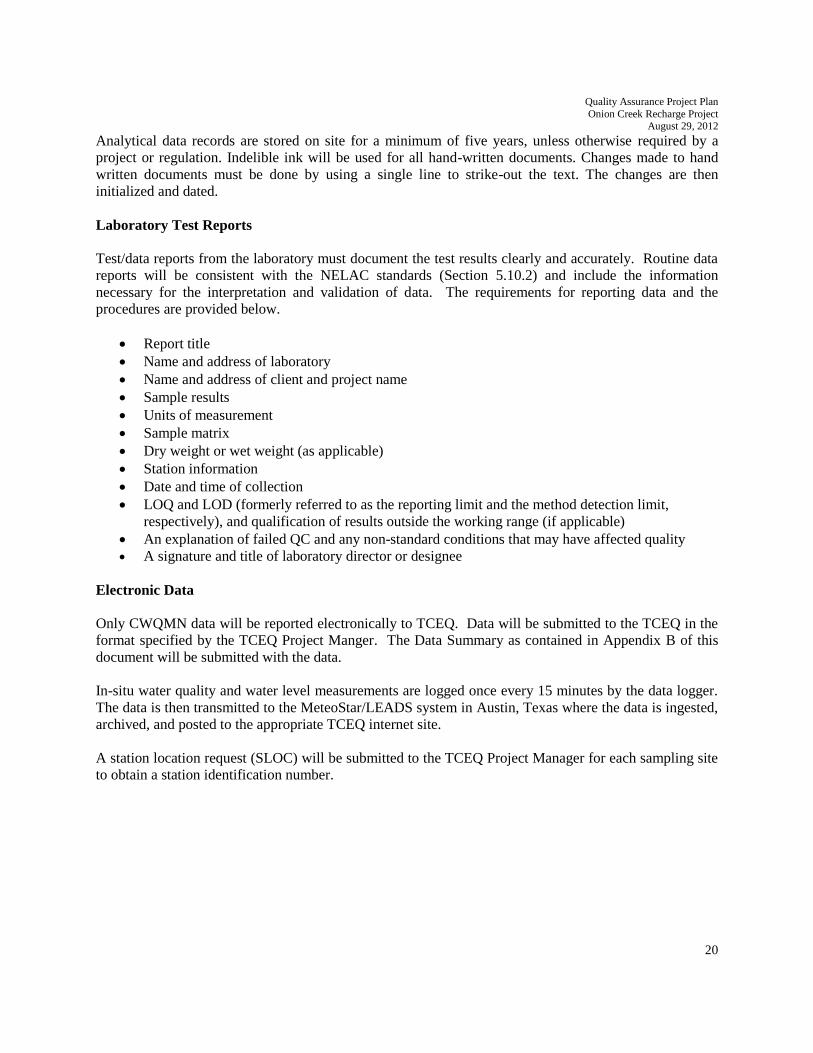
20
Analytical data records are stored on site for a minimum of five years, unless otherwise required by a
project or regulation. Indelible ink will be used for all hand-written documents. Changes made to hand
written documents must be done by using a single line to strike-out the text. The changes are then
initialized and dated.
Laboratory Test Reports
Test/data reports from the laboratory must document the test results clearly and accurately. Routine data
reports will be consistent with the NELAC standards (Section 5.10.2) and include the information
necessary for the interpretation and validation of data. The requirements for reporting data and the
procedures are provided below.
Report title
Name and address of laboratory
Name and address of client and project name
Sample results
Units of measurement
Sample matrix
Dry weight or wet weight (as applicable)
Station information
Date and time of collection
LOQ and LOD (formerly referred to as the reporting limit and the method detection limit,
respectively), and qualification of results outside the working range (if applicable)
An explanation of failed QC and any non-standard conditions that may have affected quality
A signature and title of laboratory director or designee
Electronic Data
Only CWQMN data will be reported electronically to TCEQ. Data will be submitted to the TCEQ in the
format specified by the TCEQ Project Manger. The Data Summary as contained in Appendix B of this
document will be submitted with the data.
In-situ water quality and water level measurements are logged once every 15 minutes by the data logger.
The data is then transmitted to the MeteoStar/LEADS system in Austin, Texas where the data is ingested,
archived, and posted to the appropriate TCEQ internet site.
A station location request (SLOC) will be submitted to the TCEQ Project Manager for each sampling site
to obtain a station identification number.

Quality Assurance Project Plan
Onion Creek Recharge Project August 29, 2012
21
Records and Documents Retention Requirements
Document/Record Location Retention Form QAPP, amendments, and appendices Org. 5 years Paper
QAPP distribution documentation Org. 5 years Paper
Training records Org. 5 years Paper
Field notebooks or field data sheets Org. 5 years Paper
Field equipment calibration/maintenance l Org. 5 years Paper
Chain of custody records Org. 5 years Paper
Field SOPs Org. 5 years Paper
Laboratory QA manuals Lab 5 years Electronic
Laboratory SOPs Lab 5 years Electronic
Laboratory procedures Lab 5 years Electronic
Instrument raw data files Lab 5 years LIMS Electronic
Instrument readings/printouts Lab 5 years Paper + Electronic
Laboratory data reports/results Lab 5 years Electronic
Laboratory equipment maintenance logs Lab 5 years Electronic
Laboratory calibration records Lab 5 years LIMS Electronic
Corrective action documentation Lab 5 years Electronic
B1 Sampling Process Design (Experimental Design)
B1.1 Sample Design Rationale
CWQMN
Data collected by the CWQMN system at the Antioch site is used to trigger the opening and closing of the
valve on the Antioch BMP. As a storm pulse is recognized by high turbidity readings on the CWQMN
instruments, a signal is sent automatically to the valve control mechanism for the valve to close. As
turbidity readings drop below a pre-set level that indicates approach to base flow conditions, the valve is
opened to allow the cleaner water in Onion Creek to recharge the aquifer. Data collected by the CWQMN
system at the Onion Creek Management Area CWQMN site (CAMS 0727) will be used to monitor the
amount of nonpoint source pollution in this portion of Onion Creek and to compare to the amount of
nonpoint source pollution at the Antioch site. This comparison will provide an indication of where these
pollutants are coming from within the Onion Creek watershed.
Automatic Sampling (Stormwater)
The sample design rationale for stormwater sampling for this study is based on the intent to quantify the
amount of sediment and other contaminants that are prevented from entering the Edwards Aquifer by the
automated operation of an existing BMP situated over Antioch Cave (CAMS 0770). Monitoring sites are
specified in Table B1.1. Since the valves on the BMP are closed during periods of high storm flow, the
amount of sediment and other contaminants in the surface water during this period needs to be
determined. The stormwater sampling program focuses on the collection of samples that represent the
highest amount of flow from a given storm and the collection of samples as the storm pulse subsides to
develop a water-quality profile of the stormwater event. For each sampled storm event, representative
samples will be collected to define contamination loading along the hydrograph. The first sampling event
is a first order look at the contaminant loading as a function of the hydrograph by collecting in general,

Quality Assurance Project Plan
Onion Creek Recharge Project August 29, 2012
22
one to three samples near the maximum stream flow, one or two samples will be collected as the storm
pulse is rapidly subsiding, and another one or two samples will be collected when turbidity levels of the
water are close to stabilizing. The following sampling events will focus primarily on collecting more
samples for the contaminant peak and the recession. It is estimated that the number of days between peak
flow and the time at which sediment load and turbidity have decreased to the point that the valve on the
BMP should be opened could vary between 2 to 10 days. The sampling schedule will be set to cover this
amount of time initially. As data are collected from the first storm events, the sampling schedule will be
refined.
An ISCO 3700 series automatic sampler and an ISCO 4230 bubbler flow meter were installed at Antioch.
The bubbler flow meter measures the water level (stage) in Onion Creek at the Antioch BMP. The flow
meter is programmed to log water level every 5 minutes to trigger the automatic sampler to start sampling
and could be used to pace the sample intervals based on water level. The sampler and flow meter has been
placed at such a distance and elevation from the BMP so that the sampler pump will be capable of
delivering samples to the bottles in the sampler. Because that location might not be above the maximum
flood stage for that section of Onion Creek, there is a possibility that the sampler could be inundated
under extremely high flood conditions. If that occurs, the sampler will be inspected and repaired or
replaced if necessary.
The automatic sampler has been programmed to collect samples starting when the increase in water level
indicates that the beginning of storm flow has reached Antioch. The amount of rise in water level has
been set at 1 ft, but that might be changed in the future if a lesser or greater value is more representative
of storm flow. During a storm event, samples are collected every 15 minutes to 6 hours depending on the
anticipated duration of the storm flow. Sampling will continue until the water level drops below 75
percent of the peak flow compared to flow at the start of sampling, or until 10 days after start of sampling,
whichever comes first. The cutoff for sample collection will also be evaluated periodically. The cutoff
point is likely to vary considerably for each storm event.
Each sample will be acidified as appropriate, iced and transported to the laboratory where they will be
stored at < 6 0 C prior to analysis.
Grab Samples (Base Flow)
Either before a predicted storm event, or well after a storm event, District staff will manually collect an
instream sample (grab sample) that will be representative of base flow conditions in Onion Creek. Grab
samples will be handled and analyzed as described above for automatic samples. Base flow conditions
need to be determined to better understand conditions during storm events. To the extent practicable,
grab samples will be collected following each sampled storm event. Possible exceptions will be for back-
to-back storm events for which there will be insufficient time to coordinate sampling.
Monitoring and Support Equipment
In addition to the sampling equipment mentioned above, the Antioch site includes the following
equipment:
In-Situ Troll 9500 water-quality probe (temperature, conductivity, DO, turbidity, pressure)
Zeno data logger
Enfora modem and cellular telephone
Quality Assurance Project Plan
Onion Creek Recharge Project August 29, 2012
23
ISCO 2150 flow meter with area velocity/pressure
Air compressor and tank
This equipment is part of TCEQ’s Continuous Water Quality Monitoring Network (CWQMN). The
equipment that was installed near the Antioch BMP are the Troll 9500 and Isco flow meter. An
equipment box was installed above flood stage to house the Zeno data logger, modem, communications
equipment, air compressor and tank. Cables to connect the data logger to the probes are run through a
PVC conduit that is buried in a trench for a portion of the distance between the BMP and the equipment
shed.
Data collected with the above equipment (temperature, conductivity, DO, turbidity, pressure, and stream
flow) is telemetered to the TCEQ LEADS System with a cellular telephone.
The following equipment was installed at the Onion Creek Management Area CWQMN site (CAMS
0727) as described above for the Antioch site:
In-Situ Troll 9500 multi-parameter water quality probe (temperature, conductivity, DO, turbidity,
pressure)
Zeno data logger
Enfora modem and cellular telephone
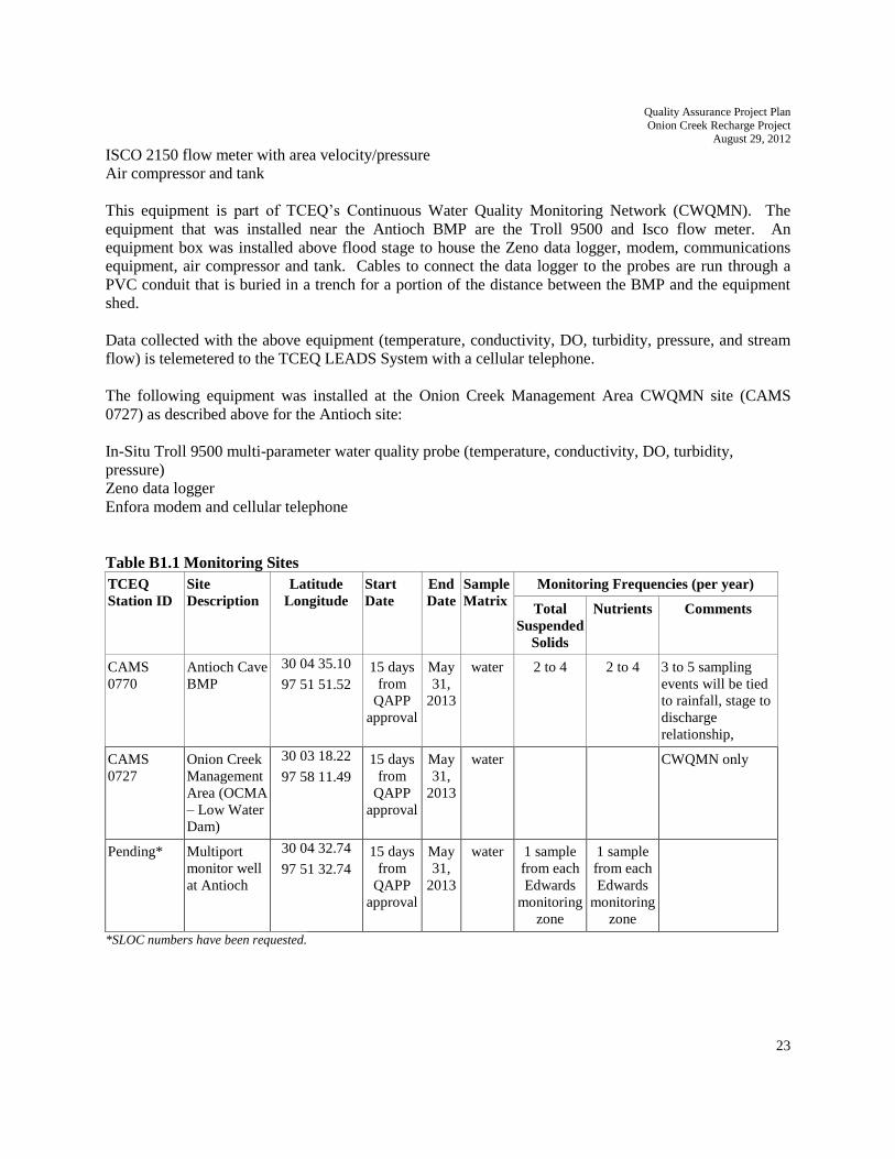
Table B1.1 Monitoring Sites
TCEQ
Station ID
Site
Description
Latitude
Longitude
Start
Date
End
Date
Sample
Matrix
Monitoring Frequencies (per year)
Total
Suspended
Solids
Nutrients Comments
CAMS
0770
Antioch Cave
BMP
30 04 35.10
97 51 51.52
15 days
from
QAPP
approval
May
31,
2013
water 2 to 4 2 to 4 3 to 5 sampling
events will be tied
to rainfall, stage to
discharge
relationship,
CAMS
0727
Onion Creek
Management
Area (OCMA
– Low Water
Dam)
30 03 18.22
97 58 11.49
15 days
from
QAPP
approval
May
31,
2013
water CWQMN only
Pending* Multiport
monitor well
at Antioch
30 04 32.74
97 51 32.74
15 days
from
QAPP
approval
May
31,
2013
water 1 sample
from each
Edwards
monitoring
zone
1 sample
from each
Edwards
monitoring
zone
*SLOC numbers have been requested.

Quality Assurance Project Plan
Onion Creek Recharge Project August 29, 2012
24
B1.2 Monitoring Station Design
Monitoring and/or support equipment are installed in weather-tight enclosures or climate controlled
trailers containing a data logger, modem, telemetry equipment, and various other support equipment.
Multiprobe Sondes
Multiprobes are typically deployed in a four inch diameter poly vinyl chloride (PVC) tube that extends
into the water body via a support structure. The lower three feet of the PVC tube is perforated to allow
water flow across the sensors. These types of installations usually utilize a weather-tight aluminum
“Traffic Box” containing a Zeno data logger, wireless cellular modem or Geostationary Operational
Environmental Satellite (GOES) communications equipment, and a deep cycle battery. Solar panels can
be installed for battery charging purposes. If wireless cellular service is available at the monitoring site a
wireless modem is used to transmit data to TCEQ. In remote areas, equipment can be installed that will
relay data using GOES.
B2 Sampling Methods
Continuous Monitoring Auto Analyzers collect and measure discrete water samples. Sondes or
Multiprobes measure water quality parameters in situ. Data from CWQMN sites are collected and stored
in a data logger via communication cables. The data are transmitted via telephone land line, wireless
modem, or Geostationary Operational Environmental Satellite GOES to the TCEQ MeteoStar/LEADS
system in Austin, Texas, where the data are ingested and archived. Averaged data are then posted to the
appropriate TCEQ internet site. Table B2.1 describes equipment, sampling method, and telemetry method
for specific CWQMN sites.
Field Sampling Procedures
Manufacturer’s Operator Manuals (MOM) for the automated flow meter, multi-parameter probe, and
automated sampler data collection are attached in Appendix C of this document.
Storm-water sample collection will follow the field sampling procedures for conventional and
microbiological parameters documented in the TCEQ Surface Water Quality Monitoring Procedures
Manual (most recent addition).
The sample volumes, container types, minimum sample volume, preservation requirements, and holding
time requirements are specified in Table B2.2.

Quality Assurance Project Plan
Onion Creek Recharge Project August 29, 2012
25
Table B2.1 Methods and Equipment for Continuous Water-Quality Monitoring
River Basin Station
Location
MeteoStar
/LEADS
Data
Averaging
Time
Sampling
Method
Measurement
Equipment
Telemetry Station Parameters
Colorado Antioch Cave
BMP
5 minute Sonde: In
situ
Troll 9500
Isco 2150
Wireless Modem Surface Temperature
Surface SC
Surface DO
Surface Turbidity
Stream Stage
Colorado Sky Ranch
Onion Creek
Management
Area (OCMA
– Low Water
Dam)
5 minute Sonde: In-
situ
Troll 9500
Wireless Modem Surface Temperature
Surface SC
Surface DO
Surface Turbidity
Stream Stage
Table B2.2 Stormwater and Base Flow Monitoring
Parameter Matrix Sample
Type
Container Preservation Sample
Volume
Holding Time
Total Dissolved
Solids
Water Grab 500 mL
HDPE
Ice, <6 °C not
frozen
500 mL 7 days
Nitrite+nitrate-N water Grab 250 mL
HDPE
Ice, <6 °C
not frozen,
H2SO4,
pH<2
250 mL 28 days
Total
Phosphorus-P
water Grab 250 mL
HDPE
Ice, <6 °C
not frozen,
H2SO4,
pH<2
250 mL 28 days
Total Suspended
Solids
water Grab 1000 mL
HDPE
Ice, <6 °C not
frozen
1000 mL 7 days
Turbidity water Grab 500 mL
HDPE
Ice, <6 °C not
frozen
250 mL 48 hours
Processes to Prevent Cross Contamination
Procedures outlined in the TCEQ Surface Water Quality Procedures Manual outline the necessary steps
to prevent cross-contamination of samples. These include such things as direct collection into sample
containers and the use of commercially pre-cleaned sample containers.

Quality Assurance Project Plan
Onion Creek Recharge Project August 29, 2012
26
Documentation of Field Sampling Activities
Field sampling activities are documented on the Field Data Reporting Form as presented in Appendix D.
For all visits, station ID, location, sampling time, sampling date, sampling depth, preservatives added to
samples, and sample collector’s name/signature are recorded. Values for all measured field parameters
collected from the sonde are recorded. Detailed observational data are recorded including water
appearance, weather, unusual odors, specific sample information, missing parameters, and flow severity.
Recording Data
For the purposes of this section and subsequent sections, all personnel follow the basic rules for recording
information as documented below:
1. Legible writing in indelible, waterproof ink with no modifications, write-overs or cross-outs;
2. Changes should be made by crossing out original entries with a single line, entering the changes, and
initialing and dating the corrections.
3. Close-outs on incomplete pages with an initialed and dated diagonal line.
Deficiencies, Nonconformances and Corrective Action Related to Sampling Requirements
Deficiencies are defined as unauthorized deviation from procedures documented in the QAPP.
Nonconformances are deficiencies which affect quality and render the data unacceptable or indeterminate.
Deficiencies related to sampling methods requirements include, but are not limited to, such things as
sample container, volume, and preservation variations, improper/inadequate storage temperature, holding-
time exceedances, and sample site adjustments.
Deficiencies are documented in logbooks, field data sheets, etc. by field or laboratory staff and reported to
the cognizant field or laboratory supervisor who will notify the BSEACD Project Manager. The
BSEACD Project Manager will notify the BSEACD QAO of the potential nonconformance within 24
hours. The BSEACD QAO will initiate a Nonconformance Report (NCR) to document the deficiency.
The BSEACD Project Manager, in consultation with BSEACD QAO (and other affected
individuals/organizations), will determine if the deficiency constitutes a nonconformance. If it is
determined the activity or item in question does not affect data quality and therefore is not a valid
nonconformance, the NCR will be completed accordingly and the NCR closed. If it is determined a
nonconformance does exist, the BSEACD Project Manager in consultation with BSEACD QAO will
determine the disposition of the nonconforming activity or item and necessary corrective action(s); results
will be documented by the BSEACD QAO by completion of a Corrective Action Report.
Corrective Action Reports (CARs) document: root cause(s); programmatic impact(s); specific corrective
action(s) to address the deficiency; action(s) to prevent recurrence; individual(s) responsible for each
action; the timetable for completion of each action; and, the means by which completion of each
corrective action will be documented. CARs will be included with quarterly progress reports. In addition,
significant conditions (i.e., situations which, if uncorrected, could have a serious effect on safety or on the
validity or integrity of data) will be reported to the TCEQ immediately both verbally and in writing.
Quality Assurance Project Plan
Onion Creek Recharge Project August 29, 2012
27
B3 Sampling Handling and Custody
See Section B10, below, for electronic managing of Continuous Water Quality Monitoring Network data.
Water quality is measured in situ for the sonde instrumentation.
Sample Labeling
Samples from the field are labeled on the container with an indelible marker. Label information includes:
1. Site identification
2. Date and time of collection
3. Preservative added, if applicable
4. Sample type (i.e., analysis(es)) to be performed
Sample Handling
The following sampling and related equipment will be required for each sampling event:
•Sample bottles for the required analyses, duplicates, field blanks, etc.
•ISCO samplers
•De-ionized water
•Ice chest
•Ice
•Field data sheets and/or field log book
•Chain-of-custody forms
•Sample labels
Immediately after filling, sample bottles will be dried and labeled.
Sample-bottle labels that are adhesive backed and capable of being attached directly to the sample
containers will be used. The following information will be entered on the sample label as a minimum:
Date
Time
Location
Sample type
Sampler name
Sample identification (ID) number
Preservative (if necessary)
Other information may be entered on the sample label if space permits. However, any information entered
on the label will not obscure the required information. Sample labels will be either be preprinted and
filled out or may be written directly on sample bottles / containers with waterproof ink.
Sample Tracking
Proper sample handling and custody procedures ensure the custody and integrity of samples beginning at
the time of sampling and continuing through transport, sample receipt, preparation, and analysis.

Quality Assurance Project Plan
Onion Creek Recharge Project August 29, 2012
28
A sample is in custody if it is in actual physical possession or in a secured area that is restricted to
authorized personnel. The COC form is used to document sample handling during transfer from the field
to the laboratory and among contractors. The following information concerning the sample is recorded on
the COC form (See Appendix E).
1. Date and time of collection
2. Site identification
3. Sample matrix
4. Number of containers
5. Preservative used
6. Was the sample filtered?
7. Analyses required
8. Name of collector
9. Custody transfer signatures and dates and time of transfer
Deficiencies, Nonconformances and Corrective Action Related to Chain-of Custody
Deficiencies are defined as unauthorized deviation from procedures documented in the QAPP.
Nonconformances are deficiencies which affect quality and render the data unacceptable or indeterminate.
Deficiencies related to chain-of-custody include but are not limited to delays in transfer, resulting in
holding time violations; incomplete documentation, including signatures; possible tampering of samples;
broken or spilled samples, etc.
Deficiencies are documented in logbooks, field data sheets, etc. by field or laboratory staff and reported to
the cognizant field or laboratory supervisor who will notify the BSEACD Project Manager. The
BSEACD Project Manager will notify the BSEACD QAO of the potential nonconformance within 24
hours. The BSEACD QAO will initiate a Nonconformance Report (NCR) to document the deficiency.
The BSEACD Project Manager, in consultation with BSEACD QAO (and other affected
individuals/organizations), will determine if the deficiency constitutes a nonconformance. If it is
determined the activity or item in question does not affect data quality and therefore is not a valid
nonconformance, the NCR will be completed accordingly and the NCR closed. If it is determined a
nonconformance does exist, the BSEACD Project Manager in consultation with BSEACD QAO will
determine the disposition of the nonconforming activity or item and necessary corrective action(s); results
will be documented by the BSEACD QAO by completion of a Corrective Action Report.
Corrective Action Reports (CARs) document: root cause(s); programmatic impact(s); specific corrective
action(s) to address the deficiency; action(s) to prevent recurrence; individual(s) responsible for each
action; the timetable for completion of each action; and, the means by which completion of each
corrective action will be documented. CARs will be included with quarterly progress reports. In addition,
significant conditions (i.e., situations which, if uncorrected, could have a serious effect on safety or on the
validity or integrity of data) will be reported to the TCEQ immediately both verbally and in writing.

Quality Assurance Project Plan
Onion Creek Recharge Project August 29, 2012
29
B4 Analytical Methods
Water quality measurement methods used by the CWQMN are based on the Standard Methods
for the Examination of Water and Wastewater, 20th Edition, 1998, unless otherwise noted. Data
comparability is achieved by following approved standardized analytical methods and operating
procedures. Methods must be documented to minimize variation in procedures and results.
Method-specific SOPs are used to document exact procedures necessary to perform the method
or operate a specific instrument or apparatus.
CWQMN method summaries are presented in Section A7. These tables include methods,
analytical techniques, performance and criteria.
Analytical system corrective actions are addressed in Section C1 of this quality assurance project
plan.
CWQMN Turbidity Measurements
Continuous water quality monitoring network turbidity measurement methods are not based on
Standard Methods for the Examination of Water and Wastewater, 20th Edition, 1998. Turbidity
measurements are made using a near infrared (780 – 900 nanometers) or monochrome light
source with 90 degree detection angle, one detector (ISO Method 7027). ISO Method designates
measurement units for this method as Formazin Nephelometric Units (FNU).
New Technology and Methodology
The CWQMN develops new sampling and measurement technology. Consequently, method
performance determination, MQOs, and SOP development, can take place after sampling and/or
measurement equipment has been deployed for testing purposes. The project leads and the
Ambient Monitoring Section are responsible for developing new sampling and measurement
technology.
New (and non-published) method performance is evaluated and documented. Method
performance for new methods is assessed for qualitative and quantitative bias, precision,
sensitivity, sampling and/or analytical system contribution, comparability, and stability by:
• Determining instrument linear range.
• Defining instrument working range using a multipoint calibration curve for each target
analyte or physical water parameter.
• Demonstrating contamination potential from sampling and preparation procedures by
analyzing blanks.
• Demonstrating calibration bias and accuracy by analyzing second source standards.
• Demonstrating measurement precision by analyzing second source standards multiple times.
• Demonstrating a measured sample is representative (i.e., measured at correct point in water
column etc.).

Quality Assurance Project Plan
Onion Creek Recharge Project August 29, 2012
30
• Determining method detection limits according to 40 CFR Part 136, Appendix B (see Section
B5).
• Determining digestion or converter efficiencies, when applicable.
• Determining known or suspected limitations.
• Comparing results obtained with new sampling or measurement technology with grab
sampling results.
Method performance results are compiled by TCEQ personnel and the data are reviewed by the
SWQM team leader, Network Coordinator, and QC support staff. TCEQ management evaluates
available resources when planning expansion of the network.
The analytical methods are listed in Table A7.1 of Section A7. Laboratories collecting data under this
QAPP are compliant with the NELAC Standards.
Copies of laboratory SOPs are retained by BSEACD and are available for review by the TCEQ.
Laboratory SOPs are consistent with EPA requirements as specified in the method.
Standards Traceability
All standards used in the field and laboratory are traceable to certified reference materials. Standards and
reagent preparation is fully documented and maintained in a standards log book. Each documentation
includes information concerning the standard or reagent identification, starting materials, including
concentration, amount used and lot number; date prepared, expiration date and preparer=s
initials/signature. The bottle is labeled in a way that will trace the standard or reagent back to preparation.
Standards or reagents used are documented each day samples are prepared or analyzed.
Deficiencies, Nonconformances and Corrective Action Related to Analytical Method
Deficiencies are defined as unauthorized deviation from procedures documented in the QAPP.
Nonconformances are deficiencies which affect quality and render the data unacceptable or indeterminate.
Deficiencies related to chain-of-custody include but are not limited to delays in transfer, resulting in
holding time violations; incomplete documentation, including signatures; possible tampering of samples;
broken or spilled samples, etc.
Deficiencies are documented in logbooks, field data sheets, etc. by field or laboratory staff and reported to
the cognizant field or laboratory supervisor who will notify the BSEACD Project Manager. The
BSEACD Project Manager will notify the BSEACD QAO of the potential nonconformance within 24
hours. The BSEACD QAO will initiate a Nonconformance Report (NCR) to document the deficiency.
The BSEACD Project Manager, in consultation with BSEACD QAO (and other affected
individuals/organizations), will determine if the deficiency constitutes a nonconformance. If it is
determined the activity or item in question does not affect data quality and therefore is not a valid
nonconformance, the NCR will be completed accordingly and the NCR closed. If it is determined a
nonconformance does exist, the BSEACD Project Manager in consultation with BSEACD QAO will
determine the disposition of the nonconforming activity or item and necessary corrective action(s); results
will be documented by the BSEACD QAO by completion of a Corrective Action Report.

Quality Assurance Project Plan
Onion Creek Recharge Project August 29, 2012
31
Corrective Action Reports (CARs) document: root cause(s); programmatic impact(s); specific corrective
action(s) to address the deficiency; action(s) to prevent recurrence; individual(s) responsible for each
action; the timetable for completion of each action; and, the means by which completion of each
corrective action will be documented. CARs will be included with quarterly progress reports. In addition,
significant conditions (i.e., situations which, if uncorrected, could have a serious effect on safety or on the
validity or integrity of data) will be reported to the TCEQ immediately both verbally and in writing.
B5 Quality Control
For a QA/QC program to be successful, it is essential that specific controls be established and maintained
throughout the measurement process. QC includes technical activities that measure the attributes and
performance of the sampling and analysis process against defined standards to verify that they meet the
needs of the project. Data quality is assessed, controlled, and measured by using SOPs, QC samples, and
audits. Specific QC samples and procedures shall be described in instrument specific SOPs.
Using a variety of control samples, a determination is made as to whether the method and instrument
performance are operating within acceptable limits. Control standards are used to check instrument
calibration and bias, blank(s) are used to assess contamination, and duplicates are used to measure
precision.
Control samples are fortified samples or blanks that are used as indicators of method and/or analytical
system performance. Each analytical method SOP specifies the necessary control sample, frequency and
performance criteria. Listed below is a synopsis of selected control samples and the information that can
be derived from each sample.
• Duplicate samples or analyses provide an indication of system or method precision.
• Blank samples or analyses may provide an indication of positive interferences.
• Fortified sample analyses provide information on analytical bias and instrument response. If fortified
samples are prepared and analyzed in duplicate, information on precision is also provided.
Program-defined measurement performance specifications are specified in Tables A7.1-3.
Sonde (Multiprobe) Temperature Sensor Checks
After every deployment period, network multi-probe temperature sensors are checked against National
Institute of Standards and Technology (NIST)-traceable thermometers and thermistors. The multi-probe
measured temperature must be within ± 0.50 º C of the NIST thermometer. If the multi-probe temperature
sensor does not meet the ± 0.50 º C criterion, the corresponding DO and SC data are invalidated.
Sampling Quality Control Requirements and Acceptability Criteria
Field Split - A field split is a single sample subdivided by field staff immediately following collection and
submitted to the laboratory as two separately identified samples according to procedures specified in the
SWQM Procedures. Split samples are preserved, handled, shipped, and analyzed identically and are used
to assess variability in all of these processes. Field splits apply to conventional samples only. One field
split will be taken for every 10 sample.
Quality Assurance Project Plan
Onion Creek Recharge Project August 29, 2012
32
The precision of field split results is calculated by relative percent difference (RPD) using the following
equation:
RPD = (X1-X2)/((X1+X2)/2))
A 30% RPD criteria will be used to screen field split results as a possible indicator of excessive variability
in the sample handling and analytical system. If it is determined that elevated quantities of analyte (i.e., >
5 times the RL) were measured and analytical variability can be eliminated as a factor, than variability in
field split results will primarily be used as a trigger for discussion with field staff to ensure samples are
being handled in the field correctly. Some individual sample results may be invalidated based on the
examination of all extenuating information. The information derived from field splits is generally
considered to be event specific and would not normally be used to determine the validity of an entire
batch; however, some batches of samples may be invalidated depending on the situation. Professional
judgment during data validation will be relied upon to interpret the results and take appropriate action.
The qualification (i.e., invalidation) of data will be documented on the Data Summary. Deficiencies will
be addressed as specified in this section under Deficiencies, Nonconformances, and Correction Action
related to Quality Control.
Laboratory Measurement Quality Control Requirements and Acceptability Criteria
Method Specific QC requirements – QC samples, other than those specified later this section, are run
(e.g., sample duplicates, surrogates, internal standards, continuing calibration samples, interference check
samples, positive control, negative control, and media blank) as specified in the methods. The
requirements for these samples, their acceptance criteria or instructions for establishing criteria, and
corrective actions are method-specific.
Detailed laboratory QC requirements and corrective action procedures are contained within the individual
laboratory quality manuals (QMs). The minimum requirements that all participants abide by are stated
below.
LOQ Check Standard – An LOQ check standard consists of a sample matrix (e.g., deionized water, sand,
commercially available tissue) free from the analytes of interest spiked with verified known amounts of
analytes or a material containing known and verified amounts of analytes. It is used to establish intra-
laboratory bias to assess the performance of the measurement system at the lower limits of analysis. The
LOQ check standard is spiked into the sample matrix at a level less than or near the LOQ for each analyte
for each batch samples that are run.
The LOQ check standard is carried through the complete preparation and analytical process. LOQ Check
Standards are run at a rate of one per analytical batch. A batch is defined as samples that are analyzed
together with the same method and personnel, using the same lots of reagents, not to exceed the analysis
of 20 environmental samples.
The percent recovery of the LOQ check standard is calculated using the following equation in which %R
is percent recovery, SR is the sample result, and SA is the reference concentration for the check standard:
%R = SR/SA * 100

Quality Assurance Project Plan
Onion Creek Recharge Project August 29, 2012
33
Measurement performance specifications are used to determine the acceptability of LOQ Check Standard
analyses as specified in Table A7.1.
Laboratory Control Sample (LCS) - An LCS consists of a sample matrix (e.g., deionized water, sand,
commercially available tissue) free from the analytes of interest spiked with verified known amounts of
analytes or a material containing known and verified amounts of analytes. It is used to establish intra-
laboratory bias to assess the performance of the measurement system. The LCS is spiked into the sample
matrix at a level less than or near the midpoint of the calibration for each analyte. In cases of test
methods with very long lists of analytes, LCSs are prepared with all the target analytes and not just a
representative number, except in cases of organic analytes with multipeak responses.
The LCS is carried through the complete preparation and analytical process. LCSs are run at a rate of one
per analytical batch. A batch is defined as samples that are analyzed together with the same method and
personnel, using the same lots of reagents, not to exceed the analysis of 20 environmental samples.
Results of LCSs are calculated by percent recovery (%R), which is defined as 100 times the measured
concentration, divided by the true concentration of the spiked sample.
The following formula is used to calculate percent recovery, where %R is percent recovery; SR is the
measured result; and SA is the true result:
%R = SR/SA * 100
Measurement performance specifications are used to determine the acceptability of LCS analyses as
specified in Table A7.1.
Laboratory Duplicates – A laboratory duplicate is prepared by taking aliquots of a sample from the same
container under laboratory conditions and processed and analyzed independently. A laboratory control
sample duplicate (LCSD) is prepared in the laboratory by splitting aliquots of an LCS. Both samples are
carried through the entire preparation and analytical process. LCSDs are used to assess precision and are
performed at a rate of one per batch. A batch is defined as samples that are analyzed together with the
same method and personnel, using the same lots of reagents, not to exceed the analysis of 20
environmental samples.
For most parameters, precision is calculated by the relative percent difference (RPD) of LCS duplicate
results as defined by 100 times the difference (range) of each duplicate set, divided by the average value
(mean) of the set. For duplicate results, X1 and X2, the RPD is calculated from the following equation:
RPD = (X1 - X2)/{(X1+X2)/2} * 100
Measurement performance specifications are used to determine the acceptability of duplicate analyses as
specified in Table A7.1. The specifications for bacteriological duplicates in Table A7.1 apply to samples
with concentrations > 10 org./100mL.
Laboratory equipment blank - Laboratory equipment blanks are prepared at the laboratory where
collection materials for metals sampling equipment are cleaned between uses. These blanks document
that the materials provided by the laboratory are free of contamination. The QC check is performed

Quality Assurance Project Plan
Onion Creek Recharge Project August 29, 2012
34
before the metals sampling equipment is sent to the field. The analysis of laboratory equipment blanks
should yield values less than the LOQ. Otherwise, the equipment should not be used.
Matrix spike (MS) –Matrix spikes are prepared by adding a known mass of target analyte to a specified
amount of matrix sample for which an independent estimate of target analyte concentration is available.
Matrix spikes are used, for example, to determine the effect of the matrix on a method’s recovery
efficiency.
Percent recovery of the known concentration of added analyte is used to assess accuracy of the analytical
process. The spiking occurs prior to sample preparation and analysis. Spiked samples are routinely
prepared and analyzed at a rate of 10% of samples processed, or one per batch whichever is greater. A
batch is defined as samples that are analyzed together with the same method and personnel, using the
same lots of reagents, not to exceed the analysis of 20 environmental samples. The information from
these controls is sample/matrix specific and is not used to determine the validity of the entire batch. The
MS is spiked at a level less than or equal to the midpoint of the calibration or analysis range for each
analyte. Percent recovery (%R) is defined as 100 times the observed concentration, minus the sample
concentration, divided by the true concentration of the spike.
The results from matrix spikes are primarily designed to assess the validity of analytical results in a given
matrix and are expressed as percent recovery (%R). The laboratory shall document the calculation for
%R. The percent recovery of the matrix spike is calculated using the following equation in which %R is
percent recovery, SSR is the observed spiked sample concentration, SR is the sample result, and SA is the
reference concentration of the spike added:
%R = (SSR - SR)/SA * 100
Measurement performance specifications for matrix spikes are not specified in this document.
The results are compared to the acceptance criteria as published in the mandated test method. Where
there are no established criteria, the laboratory shall determine the internal criteria and document the
method used to establish the limits. For matrix spike results outside established criteria, corrective action
shall be documented or the data reported with appropriate data qualifying codes.
Method blank –A method blank is a sample of matrix similar to the batch of associated samples (when
available) that is free from the analytes of interest and is processed simultaneously with and under the
same conditions as the samples through all steps of the analytical procedures, and in which no target
analytes or interferences are present at concentrations that impact the analytical results for sample
analyses. The method blank is carried through the complete sample preparation and analytical procedure.
The method blank is used to document contamination from the analytical process. The analysis of
method blanks should yield values less than the LOQ. For very high-level analyses, the blank value
should be less than 5% of the lowest value of the batch, or corrective action will be implemented.
Deficiencies, Nonconformances and Corrective Action Related to Quality Control
Deficiencies are defined as unauthorized deviation from procedures documented in the QAPP.
Nonconformances are deficiencies which affect quality and render the data unacceptable or indeterminate.
Deficiencies related to chain-of-custody include but are not limited to delays in transfer, resulting in

Quality Assurance Project Plan
Onion Creek Recharge Project August 29, 2012
35
holding time violations; incomplete documentation, including signatures; possible tampering of samples;
broken or spilled samples, etc.
Deficiencies are documented in logbooks, field data sheets, etc. by field or laboratory staff and reported to
the cognizant field or laboratory supervisor who will notify the BSEACD Project Manager. The
BSEACD Project Manager will notify the BSEACD QAO of the potential nonconformance within 24
hours. The BSEACD QAO will initiate a Nonconformance Report (NCR) to document the deficiency.
The BSEACD Project Manager, in consultation with BSEACD QAO (and other affected
individuals/organizations), will determine if the deficiency constitutes a nonconformance. If it is
determined the activity or item in question does not affect data quality and therefore is not a valid
nonconformance, the NCR will be completed accordingly and the NCR closed. If it is determined a
nonconformance does exist, the BSEACD Project Manager in consultation with BSEACD QAO will
determine the disposition of the nonconforming activity or item and necessary corrective action(s); results
will be documented by the BSEACD QAO by completion of a Corrective Action Report.
Corrective Action Reports (CARs) document: root cause(s); programmatic impact(s); specific corrective
action(s) to address the deficiency; action(s) to prevent recurrence; individual(s) responsible for each
action; the timetable for completion of each action; and, the means by which completion of each
corrective action will be documented. CARs will be included with quarterly progress reports. In addition,
significant conditions (i.e., situations which, if uncorrected, could have a serious effect on safety or on the
validity or integrity of data) will be reported to the TCEQ immediately both verbally and in writing.
B6 Instrument/Equipment Testing, Inspection and Maintenance
All instream sampling equipment testing and maintenance requirements are detailed in the TCEQ Surface
Water Quality Monitoring Procedures. Equipment records are kept on all field equipment and a supply of
critical spare parts is maintained by the BSEACD Field Supervisor. Automated sampler testing and
maintenance requirements are contained with Appendix F of this document.
All laboratory tools, gauges, instrument, and equipment testing and maintenance requirements are
contained within laboratory QAM(s). Testing and maintenance records are maintained and are available
for inspection by the TCEQ. Instruments requiring daily or in-use testing may include, but are not limited
to, water baths, ovens, autoclaves, incubators, refrigerators, and laboratory pure water. Critical spare
parts for essential equipment are maintained to prevent downtime. Maintenance records are available for
inspection by the TCEQ.
B7 Instrument/Equipment Calibration and Frequency
Before sample analysis, calibration standards are analyzed to establish instrument response, linearity, and
sensitivity. Instrument calibration is performed using calibration standards spanning the expected sample
concentrations. Concentrations or constituents are calculated using multipoint or single-point calibration
responses.
Standards
Calibration, CVS, and LCS shall be NIST - traceable standards or prepared from NIST - traceable
materials. Class “A” glassware and NIST traceable weights shall be used when making SC, pH, polymer

Quality Assurance Project Plan
Onion Creek Recharge Project August 29, 2012
36
B or formazin standards (turbidity standards), ammonia-nitrogen, nitrate-nitrogen, phosphate-phosphorus,
and TP LCS standards.
Instrument Calibrations
Multipoint and single-point calibrations are performed whenever: (1) the instrument response has drifted
so that the CVSs or other quality control checks do not meet established acceptance criteria; (2) or,
instrumentation is calibrated at routine frequencies; (3) or, prior to in situ field deployment.
Water Quality Calibration Verification Samples
Instrument calibration is periodically assessed using CVSs. These standards are analyzed to determine if
bio-fouling and/or instrument drift has caused the sensor to exceed method specific criteria. The CVS is
prepared from the same standard used to generate the initial calibration curve.
Data generated from the CVS is compared to method specific acceptance criteria. When results are
outside of the performance criteria (see Section A7), the assignable cause is determined and corrected
before sample analysis continues. Any major procedural, hardware, or software maintenance or changes
require that the system be checked for calibration drift before sample analysis.
Sonde (Multiprobe) Temperature Checks
After every deployment period, network multi-probe temperature sensors are checked against NIST-
traceable thermometers and thermistors. The TCEQ site operators have been issued spirit filled
thermometers. These thermometers are calibrated annually by TCEQ against a mercury filled NIST-
calibrated (sevenpoint) thermometer. The TCEQ’s NIST-calibrated (seven-point) thermometer has been
deemed valid for five-years between NIST traceable seven point re-calibrations.
Site operators who are cooperators are issued mercury filled NIST-calibrated (ice point) thermometers.
The TCEQ has deemed the calibration for these types of thermometers valid for five- years. When the
calibration expires the thermometers will be re-calibrated using a NIST traceable ice-point standard.
Instream field equipment calibration requirements are contained in the TCEQ Surface Water Quality
Monitoring Procedures Manual. Post calibration error limits and the disposition resulting from error are
adhered to. Data not meeting post-error limit requirements invalidates associated data collected
subsequent to the pre-calibration and are not submitted to the TCEQ. Calibration requirements for the
automated monitoring equipment (In-Situ Troll 9500) are included in Appendix G of this document.
Detailed laboratory calibrations are contained within the QAM(s).
B8 Inspection/Acceptance of Supplies and Consumables
The TCEQ procures, stores, and dispenses various spare parts, equipment, consumable items, and other
items to CWQMN TCEQ staff and Cooperators. New batches of supplies are tested before use to verify
that they function properly and are not contaminated. The laboratory QAM provides additional details on
acceptance requirements for laboratory supplies and consumables.

Quality Assurance Project Plan
Onion Creek Recharge Project August 29, 2012
37
B9 Non-direct Measurements
This quality assurance project plan does not include the use of routine data obtained from non-direct
measurement sources.
B10 Data Management
Water quality data, sample depth data, water level data and operator logs are sent to TCEQ by wireless
cellular modem.
Cellular and standard phone line data (and operator logs) are transferred to the TCEQ Headquarters
(Austin, Texas) Comms Front-End Processor (CFEP) computer through Regional Hub (Hewlett Packard
712/60) computers that automatically download data from a Zeno data logger every 15 minutes. The data
are secured from tampering or corruption over the carrier line through an unlisted telephone number, pass
code protection, and error checking protocol.
Measurement instrumentation is connected to the data logger systems. The data logger systems records
the analog output voltage of each instrument once every 15 minutes, digitizes it, and stores the data
sequentially as five-minute averages into a record. A record consists of sequential fields of data for as
many channels as are activated for each monitoring station.
If the telemetry method fails at a given site, the data loggers are capable of recording and storing data
until (number of parameter dependent) the data are overwritten with newly generated data. Once
communications are re-established the data are automatically downloaded to the CFEP computer. The
site operator should check the operational status of the station every business day via the TCEQ website.
If communication problems are detected, the site operator needs to initiate corrective action in a timely
manner or data can be lost. The site operator should alert TCEQ staff to initiate corrective action. Once
TCEQ staff has been notified, TCEQ will ensure that corrective action was taken and that the action was
effective.
The MeteoStar/LEADS processing program checks for correct date, time, sampling site number, and
proper formatting of raw data fields. For the water quality parameters it then calculates five-minute and
hourly averages, converting voltages to engineering units. The data are stored in a temporary disk file.
The BSEACD data validators work from this file through their personal computer on a graphical
interface. Data validators obtain Sonde QC information from the MeteoStar/LEADS operator log from
the RHONE Calibration Verification page, which is typically entered by the site operators and
cooperators/contractors. TCEQ site operators (with agency computers) access the MeteoStar/LEADS
TCEQ RHONE web page operator log at http://rhone/to enter operator logs. Site cooperators/contractors
who have obtained authorization can access the MeteoStar/LEADS TCEQ web page operator log via the
Virtual Private Network to enter operator logs. Operator log entries into LEADS can be made on a secure
external website at http://tceqwatercal.ipsmtx.com/.
The data validators periodically download Aqualab Analyzer QC data via telephone modem. The sonde
and Aqualab Analyzer QC results are used in the data validation process. The data maintained on the
CFEP are accessible through Internet web page reports.
After data validation, the data are coded in the file. The coded data in this file are considered “validated
data” and are archived on optical disk indefinitely.

Quality Assurance Project Plan
Onion Creek Recharge Project August 29, 2012
38
SWQMIS Data Base
A data loader is being tested that will load validated CWQMN data into the SWQMIS data base for long
term storage and management. The dataset of record will be considered the SWQMIS dataset. Once
complete, database system users will have the ability to:
• Run database reports on the CWQMN data (see the SWQMIS User’s Guide, 2007 for a
description of available reports). The report query builder allows users to specify criteria of
records to include, specify how the information is sorted in the report, and select the format for
the report output. Report output can easily be imported into other applications for further data
analysis.
• Report CWQMN data to EPA for the inclusion in the Storage and Retrieval (STORET) data
warehouse
• Visualize, using ArcIMS map features of SWQMIS, CWQMN station locations
• Access the CWQMN QAPP associated with each real-time data result
• See the history of any changes made to CWQMN data once it is stored in SWQMIS.
Only validated CWQMN parameters will be stored in the SWQMIS data base. Calculated parameters
such as total dissolved solids and salinity will not be stored in the SWQMIS. Additionally, water level
and sample depth parameters will not be stored in SWQMIS.
See Table B10.1 for a complete list of CWQMN parameters that will be stored in SWQMIS. The table
also contains a crosswalk of parameters codes from LEADS to SWQMIS.

Quality Assurance Project Plan
Onion Creek Recharge Project August 29, 2012
39
Table B10.1
SWQMIS Parameters
CFS = Cubic feet per second mg/L = milligrams/Liter µS/cm = micro Siemens / cubic centimeter NTU = nephelometric turbidity unit EC =
Degrees Centigrade Revision No. 3 Page 3 of 4 Texas Commission on Environmental Quality Section B10 Continuous Water Quality Monitoring Network Quality Assurance Project Plan (March 2012)
Data Users
Data stored in the MeteoSTar/Leads system may be provided to internal users (TCEQ data analyst, etc.)
by email, on disk, on printouts, or through TCEQ web page reports. Other internal customers have read-
only access. Public requests for CWQMN data, as well as MeteoStar/LEADS data, are made through the
Data Management & Analysis Team. Non-validated data may be released to the public with disclaimers
regarding the validity of the data.
B10.1 Data Reporting
Data collected in the CWQMN are internally hosted on the Meteostar/LEADS TCEQ RHONE data
server. Internal and external reports and summaries are compiled from data hosted on this server.
Data are reported internally on the RHONE Daily Reporting Page at various frequencies, which are
dependent upon project monitoring instrumentation. Data collected with multiprobes and level sensors
every 15 minutes are reported in the SWQM Daily Report in the 15-minute increment of their collection.
Data collected by Aqualab Auto-analyzers in one or six hour frequencies are reported in the SWQM Daily
Report in 15-minute increments, with values updated in the hour of their collection. Data collected with
Floating Vertical Profilers every hour are reported in the Profiler Daily Printout in the hour and depth of
their collection. Internal summary reports are available for all CWQMN data.
Hourly data summary reports are externally available on the TCEQ-hosted website (www.texaswaterdata
.org) for all stations in the network except Floating Vertical Profilers. Profile data are not available
Parameter LEADS Parameter
Code
SWQMIS Parameter
Code
Units
Temperature 10010 00010 ºC
Specific Conductance 10095 00094 µS/cm
Dissolved Oxygen 10300 00300 mg/L
Dissolved Oxygen,
Percent Saturation
10301 00301 %
pH 10400 00400 pH units
Ammonia-Nitrogen 10107 13851 mg/L
Nitrate-Nitrogen 10101 13852 mg/L
Total Reactive
Phosphorus
10105 17527 mg/L
Total Phosphorus 10110 17528 mg/L
Turbidity 10104 13854 NTU
USGS Gage Height 00065 Feet
USGS Water Flow Rate 00061 CFS

Quality Assurance Project Plan
Onion Creek Recharge Project August 29, 2012
40
externally, but are available upon request. See Section B10 Data Users for specific information regarding
data requests. Raw data, reported with the time of collection, are not available for external reporting.
Data Path
Samples are collected and are transferred to the laboratory for analyses as described in Sections B1 and
B2. Analytical data will be sent electronically via email from the laboratory to BSEACD. Sampling
information (e.g. site location, date, time, sampling depth, etc.) is used to generate a unique sampling
event in an interim database built on an autogenerated alphanumeric key field. Measurement results from
both the field data sheets and laboratory data sheets are manually entered into the interim database for
their corresponding event. Customized data entry forms facilitate accurate data entry. Following data
verification and validation, the data are exported in a format specified by the TCEQ project Manager.
Record-keeping and Data Storage
BSEACD recordkeeping and document control procedures are contained in the water quality sampling
and laboratory standard operating procedures (SOPs) and this QAPP. Original field sheets and copies of
the LCRA-Environmental Laboratory Services Final Analytical Reports are stored in the BSEACD
offices in accordance with the record-retention schedule in Section A9. One copy of the database is
backed up each Friday on magnetic tape and is stored off-site. If necessary, disaster recovery will be
accomplished by information resources staff using the backup database.
Data Verification/Validation
The control mechanisms for detecting and correcting errors and for preventing loss of data during data
reduction, data reporting, and data entry are contained in Sections D1, D2, and D3.
Forms and Checklists
See Appendix D for the Field Data Reporting Form. See Appendix E for the Chain-of-Custody Form.
Data Handling
Data are processed using the Microsoft Access 2000 suite of tools and applications. Data integrity is
maintained by the implementation of password protections which control access to the database and by
limiting update rights to a select user group. No data from external sources are maintained in the
database. The database administrator is responsible for assigning user rights and assuring database
integrity.
Hardware and Software Requirements
Hardware configurations are sufficient to run Microsoft Access 2000 under the Windows NT operating
system in a networked environment. Information resources staff are responsible for assuring hardware
configurations meet the requirements for running current and future data management/database software
as well as providing technical support. Software development and database administration are also the
responsibility of the information resources department. Information resources develops applications
based on user requests and assures full system compatibility prior to implementation.

Quality Assurance Project Plan
Onion Creek Recharge Project August 29, 2012
41
Information Resource Management Requirements
BSEACD information technology (IT) policy is contained in IT SOPs which are available for review at
BSEACD offices.
C1 Assessment and Response Actions
The management of the TCEQ advocates and encourages a "continuous improvement" philosophy in
personnel development and work processes. Each employee is responsible for implementing and
evaluating the effectiveness of quality improvement activities with which he/she is involved. Fostering a
"no-fault" attitude to encourage the identification of opportunities for improvement so they can be
brought to the forefront and addressed accordingly is recognized to be a critical factor in a continuous
improvement environment. Review of process performance is done on a continuous basis. This section
addresses the assessment and response actions for the CWQMN.
Based on audit reports the network coordinator may recommend to the division director and project leads
to stop work if necessary in order to safeguard programmatic objectives, worker safety, public health, or
environmental protection.
Data Completeness Assessment
Please see calculation below for how data completeness is calculated. Sites in the CWQMN may be
located in intermittent streams. Needless to say, suspension of water monitoring can occur in times of
drought. Data completeness reports will be generated and distributed quarterly.
Data completeness is calculated as follows for stream sites:
% Completeness = Number of valid measurements during stream flow x 100
Total possible measurements – Total possible measurements during no stream flow
Corrective Action
Corrective action is an essential part of any quality system and involves those procedures and actions
taken to correct situations causing data quality to fall below established expectations. The need for
corrective actions will be minimized by the implementation of applicable quality management plans,
QAPP, and the application of statistical QC to establish appropriate performance specifications limits for
measurement activities. When problems are identified at a monitoring site, the site operator shall initiate
corrective action as soon as possible. Corrective action is accomplished at the lowest level and shall be
documented in the MeteoStar/LEADS operator log. For complex problems that cannot be readily
resolved, the individual discovering the problem notifies the appropriate project lead for resolution. If the
problem cannot be resolved by the project lead, the network coordinator is notified and coordinates a
resolution to the problem with the appropriate CWQMN personnel. For complex problems, verbal and
written communication between the affected parties is started and continues until the issue is resolved.
It is expected that any individual in the CWQMN program who discovers a problem will initiate
corrective action appropriate to the situation. A formal corrective action plan for negative audit findings
and non conformances will be developed.

Quality Assurance Project Plan
Onion Creek Recharge Project August 29, 2012
42
Audit Reports
An audit report is generated for each CWQMN audit. The recipient of the audit report is the CWQMN
coordinator. Each audit report is individually numbered, dated, and identifies the auditor, auditee, and
nonconformity (findings and observations). The audit report may suggest recommended corrective action
to nonconformities.
If an audit report contains findings a written response to the findings from the network coordinator is
required within thirty days with proposed corrective action or action to be taken. The written response is
used to track and verify the proposed corrective action initiated by the finding. If a finding or proposed
corrective action is disputed and cannot be readily resolved, the recommendation is pushed to
successively higher management levels for resolution. The network coordinator is responsible for
managing this process. Corrective actions can be verified during following inspections.
Response actions to project assessments are presented in Table C1.1, including the scope of the action.

Quality Assurance Project Plan
Onion Creek Recharge Project August 29, 2012
43
Table C1.1 Assessments and Response Actions
Assessment
Activity
Approximate
Schedule
Responsible
Party
Scope Response
Requirements
Status Monitoring
Oversight, etc.
Continuous BSEACD Project
Manager
Monitoring of the project
status and records to ensure
requirements are being
fulfilled.
Report to TCEQ in
Quarterly Report
Laboratory
Inspections
Dates to be
determined by the
TCEQ lab
inspector
TCEQ Lab
Inspector
Analytical and quality
control procedures employed
at the laboratory and the
contract laboratory
30 days to respond
in writing to the
TCEQ to address
corrective actions
Monitoring Systems
Audit
Dates to be
determined by
TCEQ
TCEQ QAS The assessment will be
tailored in accordance with
objectives needed to assure
compliance with the QAPP.
Field sampling, handling and
measurement; facility
review; and data
management as they relate to
the NPS Project
30 days to respond
in writing to the
TCEQ to address
corrective actions
Laboratory Inspection Based on work
plan and or
discretion of
BSEACD
BSEACD QAO Analytical and quality
control procedures employed
at the laboratory and the
contract laboratory
30 days to respond
in writing to the
BSEACD QAO to
address corrective
actions
Monitoring Systems
Audit
Based on work
plan and or
discretion of
BSEACD
BSEACD QAO The assessment will be
tailored in accordance with
objectives needed to assure
compliance with the QAPP.
Field sampling, handling and
measurement; facility
review; and data
management as they relate to
the NPS Project
30 days to respond
in writing to the
BSEACD QAO to
address corrective
actions
Site Visit Dates to be
determined by
TCEQ
TCEQ PM Status of activities. Overall
compliance with work plan
and QAPP
As needed

Quality Assurance Project Plan
Onion Creek Recharge Project August 29, 2012
44
Corrective Action
The BSEACD Project Manager is responsible for implementing and tracking corrective action procedures
as a result of audit findings. Records of audit findings and corrective actions are maintained by both the
TCEQ PM and the BSEACD QAO.
If audit findings and corrective actions cannot be resolved, then the authority and responsibility for
terminating work is specified in the TCEQ QMP and in agreements or contracts between participating
organizations.
C2 Reports to Management
Reports to TCEQ Project Management
Monitoring Systems Audit Report and Response - Following any audit performed by the Basin Planning
Agency, a report of findings, recommendations and response is sent to the TCEQ in the quarterly progress
report.
Monitoring System Audit Response - BSEACD will respond in writing to the TCEQ within 30 upon
receipt of a monitoring system audit report to address corrective actions.
Monitoring Report- Provides data collected for the project and a summary of the data.
Reports to BSEACD Project Management
All laboratory analytical reports and applicable QA/QC data related to field and laboratory analysis will
be collected and archived by the BSEACD and LCRA ELS.
D1 Data Review, Verification, and Validation
For the purposes of this document, data verification is a systematic process for evaluating performance
and compliance of a set of data to ascertain its completeness, correctness, and consistency using the
methods and criteria defined in the QAPP. Validation means those processes taken independently of the
data-generation processes to evaluate the technical usability of the verified data with respect to the
planned objectives or intention of the project. Additionally, validation can provide a level of overall
confidence in the reporting of the data based on the methods used.
All data obtained from field and laboratory measurements will be reviewed and verified for conformance
to project requirements, and then validated against the data quality objectives which are listed in Section
A7. Only those data which are supported by appropriate quality control data and meet the measurement
performance specification defined for this project will be considered acceptable and used in the project.
The procedures for verification and validation of data are described in Section D2, below. The BSEACD
Field Supervisor is responsible for ensuring that field data are properly reviewed and verified for
integrity. The Laboratory Supervisor is responsible for ensuring that laboratory data are scientifically
valid, defensible, of acceptable precision and bias, and reviewed for integrity. The BSEACD Data
Manager will be responsible for ensuring that all data are properly reviewed and verified, and submitted

Quality Assurance Project Plan
Onion Creek Recharge Project August 29, 2012
45
in the required format to the project database. The BSEACD QAO is responsible for validating a
minimum of 10% of the data produced in each task. Finally, the BSEACD Project Manager, with the
concurrence of the BSEACD QAO, is responsible for validating that all data to be reported meet the
objectives of the project and are suitable for reporting to TCEQ.
D2 Verification and Validation Methods
All data will be verified to ensure they are representative of the samples analyzed and locations where
measurements were made, and that the data and associated quality control data conform to project
specifications. The staff and management of the respective field, laboratory, and data management tasks
are responsible for the integrity, validation and verification of the data each task generates or handles
throughout each process. The field and laboratory tasks ensure the verification of raw data, electronically
generated data, and data on chain-of-custody forms and hard copy output from instruments.
Verification, validation and integrity review of data will be performed using self-assessments and peer
review, as appropriate to the project task, followed by technical review by the manager of the task. The
data to be verified are evaluated against project performance specifications (Section A7) and are checked
for errors, especially errors in transcription, calculations, and data input. If a question arises or an error is
identified, the manager of the task responsible for generating the data is contacted to resolve the issue.
Issues which can be corrected are corrected and documented electronically or by initialing and dating the
associated paperwork. If an issue cannot be corrected, the task manager consults with higher level project
management to establish the appropriate course of action, or the data associated with the issue are
rejected.
The BSEACD Project Manager and QAO are each responsible for validating that the verified data are
scientifically valid, defensible, of known precision, bias, integrity, meet the data quality objectives of the
project, and are reportable to TCEQ. One element of the validation process involves evaluating the data
again for anomalies. Any suspected errors or anomalous data must be addressed by the manager of the
task associated with the data, before data validation can be completed.
A second element of the validation process is consideration of any findings identified during the
monitoring systems audit conducted by the TCEQ QAS assigned to the project. Any issues requiring
corrective action must be addressed, and the potential impact of these issues on previously collected data
will be assessed. Finally, the BSEACD Project Manager, with the concurrence of the QAO validates that
the data meet the data quality objectives of the project and are suitable for reporting to TCEQ.
D3 Reconciliation with User Requirements
Data collected from this project will be analyzed by the BSEACD to report the performance of the BMP
and the measured reductions in NPS loadings. The percentage of pollutant removal achieved as a result
of the storm water ponds performance will be one of several criteria examined by BSEACD in the design
and sizing of similar BMPs to be constructed in other segments of Onion Creek. Neither BMP nor
instream monitoring data that do not meet requirements will not be used in the project or submitted to the
SWQMIS.

Quality Assurance Project Plan
Onion Creek Recharge Project August 29, 2012
46
Appendix A. Area Location Map
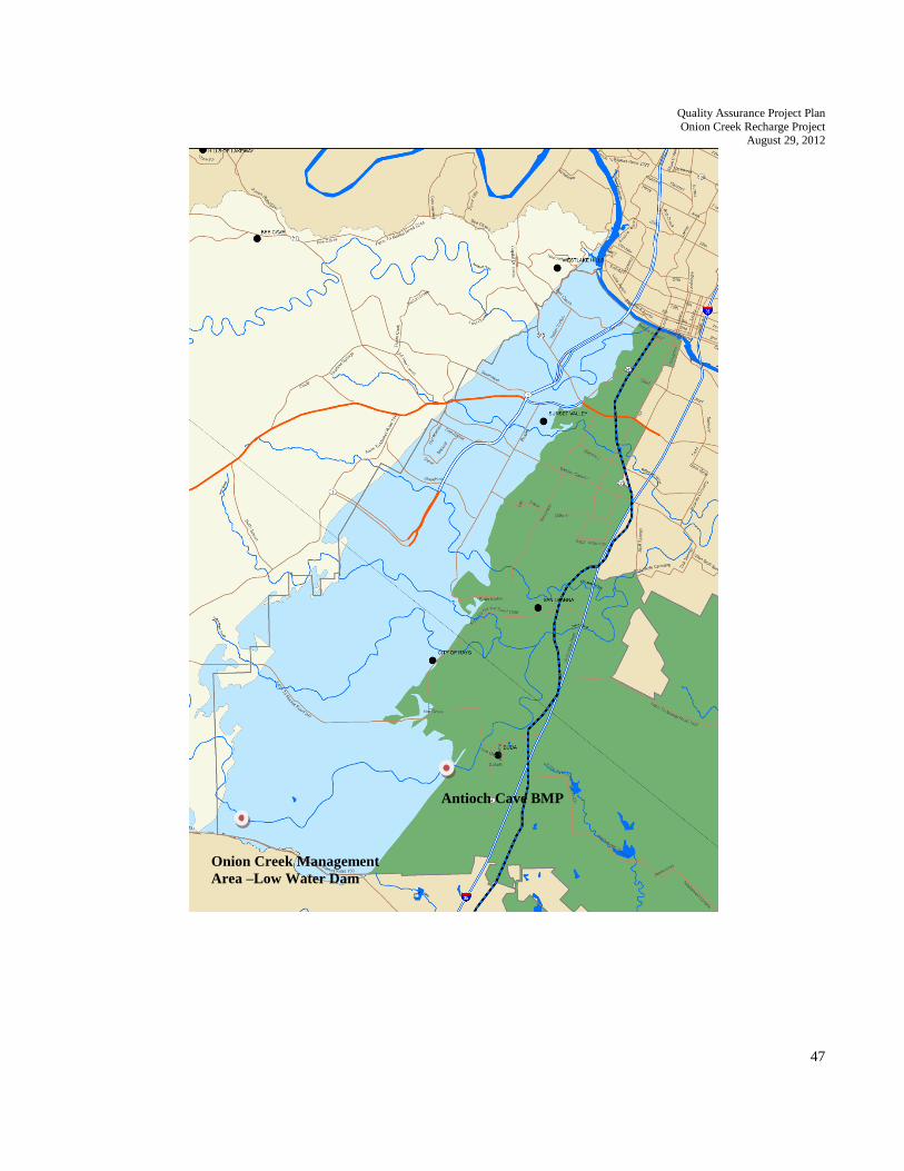
Quality Assurance Project Plan
Onion Creek Recharge Project August 29, 2012
47
Onion Creek Management
Area –Low Water Dam
Antioch Cave BMP

Quality Assurance Project Plan
Onion Creek Recharge Project August 29, 2012
48
Appendix B. Data Summary

Quality Assurance Project Plan
Onion Creek Recharge Project August 29, 2012
49
NPS DATA SUMMARY
A completed checklist must accompany all data sets submitted to the TCEQ by the Contractor.
Data Quality Review A. Are all the “less-than” values reported at or below the specified reporting limit? ___________
B. Have checks on correctness of analysis or data reasonableness performed? ___________
e.g.: Is ortho-phosphorus less than total phosphorus? ___________
Are dissolved metal concentrations less than or equal to total metals? ___________
C. Have at least 10% of the data in the data set been reviewed against the field
and laboratory data sheets? ___________
D. Are all Storetcodes in the data set listed in the QAPP? ___________
E. Are all StationIds in the data set listed in the QAPP? ___________
Documentation Review A. Are blank results acceptable as specified in the QAPP? ___________
B. Was documentation of any unusual occurrences that may affect water quality
included in the Event table’s Comments field? ___________
C. Were there any failures in sampling methods and/or deviations from sample
design requirements that resulted in unreportable data? If yes, explain on next page.
D. Were there any failures in field and laboratory measurement systems that were
not resolvable and resulted in unreportable data? If yes, explain on next page.
Describe any data reporting inconsistencies with performance specifications. Explain failures in
sampling methods and field and laboratory measurement systems that resulted in data that could not be
reported to the TCEQ. (attach another page if necessary):
Date Submitted to TCEQ: _________________________________________
TAG Series: _________________________________________
Date Range: _________________________________________
Data Source: _________________________________________
Comments (attach file if necessary): _____________________________________________________
___________________________________________________________________________________
___________________________________________________________________________________
___________________________________________________________________________________
___________________________________________________________________________________
Contractor’s Signature: _________________________________________
Date: _________________________________________

Quality Assurance Project Plan
Onion Creek Recharge Project August 29, 2012
50
Appendix C. Manufacturer’s Operator Manuals
Quality Assurance Project Plan
Onion Creek Recharge Project August 29, 2012
51

Quality Assurance Project Plan
Onion Creek Recharge Project August 29, 2012
52

Quality Assurance Project Plan
Onion Creek Recharge Project August 29, 2012
53
Appendix D. Field Data Reporting Form

Quality Assurance Project Plan
Onion Creek Recharge Project August 29, 2012
54

Quality Assurance Project Plan
Onion Creek Recharge Project August 29, 2012
55
Appendix E. Chain-of-Custody Form

Quality Assurance Project Plan
Onion Creek Recharge Project August 29, 2012
56

Quality Assurance Project Plan
Onion Creek Recharge Project August 29, 2012
57
Appendix F. Automated Sampler Testing with Maintenance and
Calibration Requirements

Quality Assurance Project Plan
Onion Creek Recharge Project August 29, 2012
58

Quality Assurance Project Plan
Onion Creek Recharge Project August 29, 2012
59
Appendix G. Standard Operating Procedures for the In-Situ Troll 9500
SOP BSEACD-001

Quality Assurance Project Plan
Onion Creek Recharge Project August 29, 2012
60
Analysis of Dissolved Oxygen (DO), Specific Conductance (SC), pH, Temperature, and Turbidity in
Ambient Surface Water Using the In-Situ Inc. Multi-Parameter Water Quality TROLL 9500
1.0 Purpose
This document describes the analytical procedures for continuous automated analysis of DO, SC, pH,
Temperature and Turbidity in ambient surface water using the In-Situ Inc. Multi-Parameter Water Quality
TROLL 9500.
2.0 Scope and Applicability
2.1 This procedure is intended for use in the Onion Creek Recharge Project.
2.2 Due to the extended length of time that TROLLs are deployed the data can be used to
establish baseline conditions, identify trends, and characterize pollution events and
seasonal variations in water quality.
2.3 SC, DO, pH, and Temperature data meeting Surface Water Quality Monitoring Data
(SWQM) Quality Objective Criteria (DQOs) may be used for the Federal Clean water
Act Sections 305(b) Report and 303(d) lists.
2.4 TROLL Turbidity measurements can be used for data validation purposes. The working
range of the sensors is listed below.
Parameter Working Range Reported Accuracy
DO (optical, RDO) 0-20 milligrams/Liter (mg/L) +/-0.2 milligrams/Liter (mg/L)
SC (low range sensor) 5-20,000 micro Siemens/cubic
centimeter (uS/cm)
+/-2 micro Siemens/cubic centimeter
(uS/cm) or 0.5% (whichever is
greater)
pH 0-12 pH Standard Units +/-0.1 pH Standard Units
Temperature -5 to 50 Degrees Celsius (OC) +/-0.1 (OC)
Turbidity (Nephelometer,
90o light scattering, 870 nm
LED, solid state)
0-2000 Nepholometric Turbidity
Units (NTU)
+/-3 Nepholometric Turbidity Units
(NTU) or +/-5% (whichever is
greater)
Standard Operating Procedure (SOP) BSEACD-001
Title: Analysis of Dissolved Oxygen (DO), Specific Conductance (SC), pH, Temperature, and Turbidity in
Ambient Surface Water Using the In-Situ Inc. Multi-Parameter Water Quality TROLL 9500
Team Leader:_______________________________ Date:________________________ Quality Control
Review:______________________ Date:________________________ Section
Manager:____________________________ Date:________________________ Effective
Date:______________________________

Quality Assurance Project Plan
Onion Creek Recharge Project August 29, 2012
61
3.0 Method Summary
3.1 The TROLL is deployed in the water body of interest, or ambient surface water is
pumped through a flow cell near the water body of interest, and DO, SC, pH,
Temperature and Turbidity are measured in situ.
3.2 The DO is measured with an optical sensor that uses the principle of “dynamic
luminescence quenching”. With this principle, “lumiphore” molecules fluoresce when
excited by light of a specific wavelength. The oxygen molecules present act to quench
this fluorescence. The “lumiphores” in the sensor are embedded in a gas-permeable
sensing foil in a replaceable cap. The sensor optics includes a lens, blue LED with filter,
red LED with filter and a photodetector. When the blue LED emits light, the sensing foil
emits red photons; the presence of oxygen in the foil causes a reduction in red light
detected by the photodiode. The phase difference between the blue excitation light and
the returned red light is measured and the result is used to compute dissolved oxygen.
This method measures the “phase” (or delay) of the returned signal and is thus based on
the “lifetime” rather than the “intensity” of the luminescence. The RDO optical dissolved
oxygen sensor does not consume oxygen does not consume oxygen and thus it does not
require flow past the sensor for measurement of DO. The RDO sensor does not require
conditioning before use or frequent calibration.
3.3 The Electrical Conductivity (EC) sensor is a flow cell with four electrodes. The four
electrodes consist of two drive electrodes and two sensing electrodes.
Conductivity/specific resistance is measured through an
3.4 The pH sensor uses a potentiometric method to measure the pH of the solution. The pH
sensor consists of a pH-sensitive glass whose voltage is proportional to the hydrogen ion
concentration. A second sensor (electrode) serves as a reference, which supplies a
constant stable output. Electrical contact is made with the solution using a saturated
potassium chloride (KCl) solution. The electrode behavior is described by the Nernst
equation: Em = Eo + (2.3 RT/nF) log [H+] where Em is the potential from the pH
electrode, Eo is related to the potential of the reference electrode, R is the Gas Law
constant, F is Faraday’s constant, T is the Temperature in Kelvin, n is the ionic charge
(+1 for Hydrogen) and [H+] is the hydrogen ion concentration in moles/L. The MP
TROLL 9500 reads the signal from the pH electrode, the reference electrode and the
temperature and then calculates the pH using the Nernst equation.
3.5 Surface water Temperature is measured by a platinum resistance thermometer
3.6 The turbidity sensor is an electronic Nephelometer, which compares the intensity of light
scattered by the ambient water with the intensity of the light scattered by a standard
reference suspension. The higher the intensity of scattered light, as measured in
Nephelometric Turbidity Units (NTUs), the higher the turbidity. The turbidity sensor
consists of a matched solid-state photodiode detector/emitter pair positioned at right
angles. The light source is an infrared LED, optimized for operation at 870 nanometers
(nm) with a photodiode detector. The sensor uses a detection angle of 90 degrees and a

Quality Assurance Project Plan
Onion Creek Recharge Project August 29, 2012
62
light wavelength of 860 nm. The sensor uses active modulation for ambient light
rejection.
3.7 The pressure transducer senses changes in pressure, measured in force per square unit of
surface area, exerted by a column of water or other fluid. With a vented or “gauged”
pressure sensor, a vent tube in the cable applies atmospheric pressure to the back of the
strain gauge. The basic unit for vented measurements is psig (pounds per square inch
“gauge”), measured with respect to atmospheric pressure. PGIS sensors exclude the
atmospheric or barometric pressure component.
4.0 Limitations
4.1 Do, EC, pH and Turbidity sensors can become fouled due to bacteria, algae and chemical
deposits. In some water bodies (or due to seasonal variation in water quality) sensor
fouling can occur rapidly, decreasing deployment periods. Some In-Situ MP TROLL
9500s are equipped with a mechanical wiper brush that cleans turbidity sensor tips. This
capability can increase deployment periods in some water quality conditions.
4.2 In rivers that have high sediment loading, sensors can periodically become covered with
sediment.
4.3 Electrolytic conductivity increases with temperature. Significant errors can result from
inaccurate temperature measurements.
4.4 The glass pH electrode is relatively free from interference from color, turbidity, colloidal
matter, oxidants, reductants, or highly salinity, except for sodium error at pH>10. pH
measurements are affected by temperature and can cause long term drift. The pH
electrode can only accurately measure up to 12 standard units.
4.5 Expired standards should not be used.
5.0 Safety
This procedure includes processes that can be hazardous. Therefore, before attempting this process,
review the TCEQ Chemical Hygiene Plan for proper equipment and procedures necessary for the safe
completion of this procedure. Operators must read and be familiar with the Material safety Data Sheets
for all reagents listed in section 6.0 of this document. Lab Coasts, safety glasses with side shields and/or
splash goggles, and chemical resistant gloves should be worn when handling harmful chemicals. Some of
these chemicals have the potential to be skin and eye irritants.
6.0 Equipment and Reagents
6.1 Equipment
6.1.1 In-Situ Multi Parameter TROLL 9500 with EC, RDO, pH, Pressure,
Temperature, and Turbidity Sensors.

Quality Assurance Project Plan
Onion Creek Recharge Project August 29, 2012
63
6.1.2 RS232 Connection Cable
6.1.3 Personal Computer
6.1.4 Instrument Logbook
6.1.5 Calibration Forms
6.1.6 Calibration Cup
6.1.7 Ring Stand and Clamp
6.1.8 Thermistor or Thermometer traceable to National Institute of Standards and
Technology (NIST) with a 0.1oC tolerance.
6.1.9 100 ml volumetric flask
6.1.10 100-1000 ml pipette
6.1.11 100-1000 ml pipette tips
Optional Equipment
6.1.12 Peristaltic Pump
6.1.13 TROLL 9500 Flow Cell
6.2 Standards and Reagents (All reagents/chemicals must be AR grade)
6.2.1 pH 7.00 +/-0.01 S.U. @ 25oC Buffer (ACS traceable reagent grade Dibasic
Sodium Phosphate Na2HPO4 – Monobasic Potassium Phosphate KH2PO4
Buffer)
6.2.2 pH 10.00 +/-0.02 @ 25oC Buffer (ACS traceable reagent grade Potassium
Carbonate K2CO3 – Potassium Borate K[B5O6(OH)4] – Potassium Hydroxide
KOH Buffer)
6.2.3 12890 micromhos/cm @ 25 oC Conductivity/TDS Standard (ACS traceable
reagent grade Potassium Chloride KCl in reagent grade deionized water H2O
6.2.4 10, 100, 1000 NTU Polymer Turbidity Standard for In-Situ (Styrene
Divinylbenzene Copolymer beads, deionized water, trace sodium azide (0.01%,
added as preservative)
6.2.5 Deionized (DI) Type I water

Quality Assurance Project Plan
Onion Creek Recharge Project August 29, 2012
64
6.2.6 0 mg/L Dissolved Oxygen/Zero Oxygen Standard (ACS Reagent Grade Sodium
Sulfite, trace Cobalt Chloride)
7.0 Procedure
Before water quality is monitored, the sensors are calibrated and quality control (QC) samples are
analyzed at a minimum of once a month (30days). The station’s water quality parameters are monitored
by the site operator, remotely, or with weekly data downloads to a laptop computer, to evaluate
operational status of the station.
7.1 Monitoring
The TROLL measures ambient surface water while in situ. The TROLL can be deployed in poly
vinyl chloride (PVC) tubing that is attached to a support structure. Alternatively, the TROLL can
be placed in an enclosure near the edge of the stream bank and water can be pumped up to a flow
cell which covers the sensors.
7.1.1 The TROLL should be deployed in a representative section of the water body.
When monitoring rivers and streams, the TROLL should be located as close as
possible to the centroid of flow. Centroid is defined as the midpoint of that
portion of stream or river width which contains 50 percent of the total flow.
7.1.1.1 Alternatively, if water is pumped through a flow cell containing the
TROLL sensors then the inlet hose should be place near the centroid of
flow in the stream.
7.1.2 Sensors should be positioned at approximately one foot (0.3 m) of water depth.
Areas of excessive vegetation, turbulence, or silt should be avoided.
7.1.2.1 Alternatively, if an inlet hose is used to pump water up to the flow cell
containing the instrument sensors, the inlet hose should be attached to the
top of a weight, at a fixed position above the bottom of the stream.
7.1.3 Drill holes in the PVC to allow for an exchange of water into the tubing.
7.1.4 Adjust the TROLL periodically due to fluctuations in water levels of the water
body.
7.2 Station Monitoring
The site operator should monitor water quality and other parameters daily to ensure the station is
operational.
7.2.1 Every business day, the site operator will monitor (via TCEQ website
http://www.texaswaterdata.org) and screen EC, DO, pH, Temperature,
and Turbidity measurements for anomalies. If problems are identified, a
site visit may be needed to correct any problems.

Quality Assurance Project Plan
Onion Creek Recharge Project August 29, 2012
65
7.2.2 If online data are not available, the sire operator shall visit the site once
per week.
7.3 DO, EC, pH, and Turbidity Sensor Calibration Verification Samples (CVS) and
Temperature QC.
EC, DO, and pH CVSs are analyzed and the sensors are re-calibrated at a minimum of once every
month. Turbidity CVSs are analyzed at a minimum of once every month, but the Turbidity sensor
is only recalibrated if the CVS check standard shows more than a +/-5.0 % recovery difference
from the nominal. More frequent sensor re-calibrations may be needed in high fouling
environments. The site operator will need to determine sensor re-calibration frequency for their
water body. Temperature and pressure sensors are checked monthly. Note: The TCEQ Surface
Water Quality Monitoring Program has used the phrase “Post-Calibration” to describe QC
samples used to assess analytical drift from previous sensor calibrations. For the purposes of this
document, CVS is used in place of “Post-Calibration”.
7.3.1 EC, DO, pH and Turbidity CVS are analyzed at a minimum of once every month
(or more frequently), before the TROLL EC, DO, pH and Turbidity sensors are
re-calibrated.
7.3.1.1 A check of a CVS standard can be made by connecting to the TROLL
with the Win-Situ software and a laptop PC and selecting the TROLL in
the Navigation tree.
7.3.1.2 The TROLL is washed with tap water and deionized water and shaken to
remove the water.
7.3.1.3 The TROLL sensor is placed into the applicable CVS standard.
7.3.1.4 Select one of the appropriate parameter in the Win-Situ display and Tap
the “Read” button in the navigation window. Multiple parameters can be
selected and read at the same time by holding down the control key on
the keyboard while selecting parameters. The Temperature parameter
should be read alongside all of the other CVS readings.
7.3.1.5 Record the CVS reading and temperature for each parameter in the
calibration logbook.
7.3.2 The Temperature sensor should be checked against an NIST traceable
thermometer at the same time that CVS samples are analyzed. If the sensor does
not meet the acceptance criteria listed in Table 9-1, the temperature data must be
invalidated back to the last temperature check. For further details, see Section
9.0.
7.3.3 The pressure sensor should also be checked at the same time that CVS samples
are analyzed. The vented or “gauged” pressure transducer should be verified in

Quality Assurance Project Plan
Onion Creek Recharge Project August 29, 2012
66
open air, where it should read zero plus or minus the acceptable electronic drift
offset from zero.
7.3.4 If barometric pressure for DO calibrations is determined by barometer, the
accuracy of the barometer will need to be checked once a year.
7.4 EC, DO, pH and Turbidity Sensor Calibration
DO, EC, and pH calibrations are performed at least once a month, prior to TROLL deployment,
and after the monthly EC, DO, pH and turbidity CVSs have been analyzed. A Turbidity sensor
calibration is performed if the Turbidity CVS recovery is reported at +/-5.0% of the known value
of the standard, otherwise maintaining factory calibration is recommended. After the EC, DO,
pH and Turbidity sensor calibrations, calibration parameters/constants are recorded in the
instrument logbook.
Note: Perform calibrations and analyze EC, DO, pH and Turbidity CVSs as close to
25.0oC as possible in a temperature controlled environment.
Note: Perform the EC calibration before the calibration of the pH sensor.
Barometric pressure measurements for DO calibrations can be obtained at the National
Weather Service.
Allow the TROLL and calibration standards time to equilibrate (a minimum of 2
minutes) before calibration(s) or initial readings.
Secure the TROLL in a vertical orientation (by length).
Before calibration, make sure plugs are installed in empty sensor ports.
Ensure that all sensors are immersed in the applicable calibration standard before
calibration.
Use a small amount tap water and deionized water to pre-rinse the sensors between each
sensor calibration.
Have several clean absorbent paper towels. Shake the excess rinse water off the TROLL
between sensor calibrations. This will reduce carry –over contamination of calibration
solutions.
Connect the TROLL to a laptop computer with a standard RS232 Serial Port.
Open the Win-Situ 4.0 software on a laptop computer.
Manually connect to the TROLL by selecting the appropriate COM port in the Win-Situ
software and mouse-clicking the “Find” button.
7.4.1 Single-Point EC Calibration
The calibration of the EC sensor consists of a single-point calibration with a 12890
micromhos/cm Conductivity Standard. A high-value standard is recommended because it
has the ability to remain stable over longer periods of time. The conductivity calibration
curve is linear over the whole range of the sensor, making it unnecessary to calibrate with
a standard concentration closer to the expected conductivity of the water body. During

Quality Assurance Project Plan
Onion Creek Recharge Project August 29, 2012
67
the calibration, the In-Situ TROLL will measure the temperature of the standard and
automatically calculate the (non-normalized) conductivity of the standard.
7.4.1.1 Rinse the EC sensor with tap water followed by deionized water.
7.4.1.2 Shake the probe to remove the rinse water from the sensor.
7.4.1.3 Pour the calibration standard into a beaker and insert the MP TROLL
9500 Turbidity sensor into the solution.
7.4.1.4 Connect the MP TROLL 9500 to a PC and establish a connection with
the Win-Situ 4 software.
7.4.1.5 Select the MP TROLL 9500 in the Navigation tree.
7.4.1.6 Select conductivity in the Parameters list. The sensor serial number
and recent calibration information is shown.
7.4.1.7 Select Calibrate
7.4.1.8 Select the “Other” row under the Calibration setup screen and type
12890 into the space provided. The number typed is the conductivity
of the calibration solution.
7.4.1.9 Select the “Next” button
7.4.1.10 Select the “Run” button.
7.4.1.11 Wait for the word “Stable” to appear on the calibration screen at
which point the display screen will automatically advance.
7.4.1.12 A final screen will appear containing the conductivity cell constant for
this calibration. Record this value in the calibration logbook and press
the “Finish” button on the display.
7.4.1.13 Record the Temperature during calibration, the Sensor Reading in
ohms and the Sensor Deviation in the calibration logbook.
7.4.2 Two-Point pH Calibration
The pH calibration requires two pH buffer solutions (pH 4.00 and 7.00 or pH 7.00 and
10.00). Choose the solutions that bracket the expected pH range of the water body.
7.4.2.1 Rinse the pH sensor with tap water followed by deionized water.
7.4.2.2 Shake the probe to remove the rinse water from the sensor.

Quality Assurance Project Plan
Onion Creek Recharge Project August 29, 2012
68
7.4.2.3 Pour the first calibration standard into a beaker and insert the MP
TROLL 9500 Turbidity sensor into the solution.
7.4.2.4 Connect the MP TROLL 9500 to a PC and establish a connection
with the Win-Situ 4 software.
7.4.2.5 Select the MP TROLL 9500 in the Navigation tree.
7.4.2.6 Select pH in the Parameters list. The sensor serial number and recent
calibration information is shown.
7.4.2.7 Select Calibrate to launch the pH Calibration Wizard.
7.4.2.8 Change the number of calibration points to 2 in the drop down menu.
7.4.2.9 Select the values of the two calibration points that will be used in the
drop down menus.
7.4.2.10 Select “Next” to continue.
7.4.2.11 Select “Run.” The screen will automatically advance when the word
“Stable” is displayed under the stabilization readings column.
7.4.2.12 Remove the pH sensor from the first calibration solution and wash it
with tap water and deionized water.
7.4.2.13 Place the sensor into a beaker containing the second calibration
solution. Select “Run” to begin the stabilization process.
7.4.2.14 The word “Stable” will appear and automatically advance the screen.
7.4.2.15 Record the pH slope and offset milli-volts (mV) for the pH 7.00 and
pH 10.00 solutions in the calibration logbook and press “Finish” to
apply the calculated calibration.
7.4.3 DO Calibration
The DO sensor is calibrated in water that is 100 % saturated with air. An oxygen bubbler
is placed into beaker of tap water and allowed to run for at least 5 minutes prior to the
calibration procedure. However, after replacing the DO sensor caps a two point
calibration (100% and 0%) is recommended. It’s important to note that the DO
calibration procedure is very sensitive to changes in temperature; therefore it should be
done in an area protected from direct sunlight and away from ventilation ducts.
7.4.3.1 Rinse the RDO sensor with tap water followed by deionized water.
7.4.3.2 Shake the probe to remove the rinse water from the sensor.

Quality Assurance Project Plan
Onion Creek Recharge Project August 29, 2012
69
7.4.3.3 If necessary, utilize a lens wipe to clean the sensor lens.
7.4.3.4 Submerge the RDO sensor in a beaker of tap water aerated with a
bubbler. Ensure that the sensor is completely submerged and the
sensor cap is not directly in the bubble stream. The bubbler is
allowed to run for 5 to 10 minutes before continuing.
7.4.3.5 Connect the TROLL 9500 to a PC and establish a connection with
the Win-Situ 4 software.
7.4.3.6 Select the TROLL 9500 in the Navigation tree on the display screen.
The software will automatically detect and display the installed
sensors.
7.4.3.7 Select Rugged Dissolved Oxygen in the Parameters list. Information
on the RDO sensor is shown, including its serial number (SN).
7.4.3.8 Select Calibrate
7.4.3.9 A screen will ask if the barometric pressure settings should be edited
at this time. Since the Troll 9500 is usually on a vented cable and
will take measurements using a vented cable, click “No”. For
instances when the device is calibrated using a vented cable but will
take measurements using a non-vented cable, click “Yes”. On the
next screen, check the box indicating a non-vented cable for
measurements but vented cable for calibration/programming.
7.4.3.10 Select the “Calibrate” option on the next screen. Press the “Run”
button on the screen.
7.4.3.11 When the Temperature and Dissolved Oxygen readings have
stabilized; the screen will show the word “Stable” in the status row.
Record these values in the calibration logbook and select the “Next”
button two times to use the factory calibrated 0% saturation value. If
conducting a Zero Oxygen Point calibration, select “Next” once to
display Zero Oxygen Point Screen.
7.4.3.11.1 Immerse the DO sensor in an oxygen depleted
medium of Sodium sulfite (Na2SO3) solution.
7.4.3.11.2 When ready to take calibration point, click Run
in Zero Oxygen Point screen. Wait for readings
to stabilize.
7.4.3.11.3 Select “Next” to finalize the calibration.

Quality Assurance Project Plan
Onion Creek Recharge Project August 29, 2012
70
7.4.3.12 The final calibration screen for a 1-point calibration at saturation will
be displayed on the screen. Press “Finish” to apply the calibration.
7.4.4 Turbidity Sensor Calibration
The Turbidity Sensor is factory calibrated over its full range, 0 to 2000 NTU, using
polymer standards; however instrument drift can occur over extended periods of
deployment. A turbidity sensor calibration will only need to be performed when the
turbidity calibration verification standard (CVS) from the previous deployment falls
outside of the accepted quality control criteria. The CVS should always read between +/-
5.0 % or 3 NTU of the stated value of the standard; if the CVS is beyond this acceptable
Percent Recovery criteria it is recommended to reset default coefficients and restore
factory accuracy.
7.4.4.1 Resetting Default Coefficients:
The sensor’s factory calibration may be reset back to factory defaults at any time. As
long as there is no contamination on the optical windows, this will restore the factory
accuracy (+/- 5% or 2 NTU).
7.4.4.12 Establish a connection to the instrument in Win-Situ 4.
7.4.4.13 Select Turbidity in the Parameters list and click calibrate.
7.4.4.14 In the first screen, select Use Default Coefficients, then Next.
7.4.4.15 In the final screen, click Finish to restore the sensor’s factory
calibration coefficients.
If the Percent Recovery does not meet the acceptable criteria after resetting
default coefficients, it is then necessary to conduct a three point calibrations with an
instrument specific polymer standard calibration (0 NTU, 10 NTU, 100 NTU).
7.4.4.16 Rinse the Turbidity sensor with tap water followed by deionized
water.
7.4.4.17 Shake the probe to remove the rinse water from the sensor.
7.4.4.18 Pour the calibration standard into an opaque beaker (to reduce stray-
light scatter) and insert the MP TROLL 9500 Turbidity sensor into
the solution.
7.4.4.19 The windows of the turbidity sensor should be submersed at least
0.25” deep in the solution.
7.4.4.20 If no wiper blade is present on the sensor, gently agitate the
instrument to dispel any air bubbles.

Quality Assurance Project Plan
Onion Creek Recharge Project August 29, 2012
71
7.4.4.21 Connect the MP TROLL 9500 to a PC and establish a connection in
Win-Situ 4. Select the MP TROLL 9500 in the navigation tree. This
will display the installed sensors (including the Turbidity sensor).
7.4.4.22 Click to select Turbidity in the Parameters list. The sensor serial
number (S/N) and recent calibration information is displayed.
7.4.4.23 Select Calibrate. The turbidity calibration wizard will start
automatically.
7.4.4.24 Select the Standard Calibration Option.
7.4.4.25 Select the Next button to continue.
7.4.4.26 Change the number of calibration points to 4 from the drop down
menu.
7.4.4.27 Select the values of the three turbidity calibration solutions in the
drop down menus for each point (Cal 1 = 0 NTU, Cal2 = 10 NTU,
Cal3 = 100 NTU).
7.4.4.28 The first calibration point will always be 0 NTU and will be
calibrated with Type I Deionized water.
7.4.4.29 Press the Next Button to continue.
7.4.4.30 The value of the first calibration standard will be shown on the
screen. Immerse the Turbidity sensor in the first calibration standard
and press the “Run” button to calibrate the first calibration point. The
“Accept” button becomes available when nominal stability is
achieved. Continue to wait for the instrument to display the word
“Stable” and automatically advance the screen to the next calibration
point.
7.4.4.31 Discard the previous solution, rinse the beaker and the front end of
the instrument with tap water and deionized water, then refill the
beaker with the second calibration standard.
7.4.4.32 Select the “Run” button to calibrate the next calibration point. Wait
for the screen to show “Stable” and automatically advance to the
next calibration point.
7.4.4.33 Repeat steps 7.4.4.31-7.4.4.32 for the final two calibration points.
7.4.4.34 The final screen will show the sensor slope and offset calculated
during the calibration process. A slope and offset value will also be

Quality Assurance Project Plan
Onion Creek Recharge Project August 29, 2012
72
shown for each point in used in the calibration. Record these values
in the Calibration Logbook.
7.4.4.35 Select the “Finish” button on the display to program the sensor with
the calculated calibration coefficients.
8.0 Calculations
8.1 Seal Level Corrected Barometric Pressure Uncorrected to Actual Barometric Pressure
This equation is used to uncorrected sea level corrected barometric to actual barometric pressure.
Local barometric pressure obtained from the National Weather Service is corrected to sea level
and is usually reported in inches of Hg (inches HG x 2.54 = mm Hg).
ABP = CBP – (2.5 mm Hg)(A/100)
Where:
ABP = Actual Barometric Pressure in mm Hg.
CBP = Barometric Pressure corrected to sea level in mm Hg.
A – local altitude in feet above mean sea level.
2.5 mm Hg = constant.
8.2 Sample Conductivity
Electrical Conductivity is reported as SC using Equation 8.2.1
8.2.1 SC is actual conductivity corrected to 25oC:
SC = (AC)/(1 + 0.0191 x (t-25.0))
Where:
AC = non-standardized conductivity in uS/cm.
t = the solution temperature in degrees Celsius.
8.2.2 To determine un-normalized (raw) conductivity standard EC concentration from
normalized Raw EC = normalized EC in uS/cm (1 + 0.0191 (temp measured –
25)).
8.3 QC calculations
X1 X 100
8.3.1 Recovery (percent recovery) = X2
Where:
X1 = measured CVS concentration
X2 = theoretical (known) CVS concentration

Quality Assurance Project Plan
Onion Creek Recharge Project August 29, 2012
73
9.0 QC Samples
Note: Analyze EC, DO, pH and Turbidity CVSs as close to 25.0oC as possible.
QC samples are used to ensure that acceptable data quality is maintained throughout the process and to
help assess data validation. The QC samples analyzed for this method are performed on a monthly basis,
or more frequently as determined by the site operator. Any deviation from the procedure documented in
the SOP, including any QC samples which do not meet the frequency requirement or acceptance criteria,
need to be documented in the operators log. The log entry should contain a description of the exception,
the cause (if possible), the affected data, and the impact on data. Any affected data should be qualified
accordingly. Note: A failing CVS can be followed by a single replicate analysis to determine if there is a
systematic problem. If the reanalysis meets all acceptance criteria, the system may be deemed as
providing acceptable data. Conducting multiple analyses to single passing QC samples when no
corrective action as a result of an assignable cause or instrument maintenance is performed is not
acceptable. In other words, if the original QC sample or its rerun passes, then the failing QC analysis is
considered to be an anomaly, its results are not used for data assessment.
EC QC Samples
9.1 An EC CVS is analyzed at a minimum of once monthly (before calibration of the EC
sensor) to assess analytical drift from the previous calibration. The CVS should be the
same standard used to generate the initial single-point calibration.
9.2 The CVS Calibration solution is introduced using a beaker or Cal Cup. Rinse the sensor
with Tap water followed by DI Water and shake off the water before introducing the
CVS. The Percent Recovery of the CVS should be 5.0%. If the CVS does not meet
acceptance criteria, the previous month’s EC (back to the last EC calibration) data should
be invalidated. Note: a failing CVS could be the result of an aged EC CVS standard. If
CVS failed, re-analyze the CVS using a fresh EC standard. CVS results should be entered
into the operator log and instrument logbook.
DO QC Samples
The Amount of DO in a sample is pressure and temperature dependent.
9.3 A DO CVS is analyzed a minimum of once monthly (before calibration of the DO
sensor) to assess analytical drift from the previous calibration. The CVS consists of
percent saturation in air-saturated water using procedures in Section 7.4.3.
9.4 This reading should be within +/-6.0 % saturation of 100 %.
9.5 If the CVS does not meet acceptance criteria the previous month’s DO (back to the last
passing CVS or DO calibration) data should be invalidated. CVS results should be
entered in the operator log. The results should also be logged in the Instrument Logbook
and/or recorded in the Calibration Logbook.
pH QC Samples
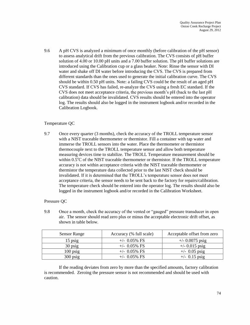
Quality Assurance Project Plan
Onion Creek Recharge Project August 29, 2012
74
9.6 A pH CVS is analyzed a minimum of once monthly (before calibration of the pH sensor)
to assess analytical drift from the previous calibration. The CVS consists of pH buffer
solution of 4.00 or 10.00 pH units and a 7.00 buffer solution. The pH buffer solutions are
introduced using the Calibration cup or a glass beaker. Note: Rinse the sensor with DI
water and shake off DI water before introducing the CVS. The CVS is prepared from
different standards than the ones used to generate the initial calibration curve. The CVS
should be within 0.50 pH units. Note: a failing CVS could be the result of an aged pH
CVS standard. If CVS has failed, re-analyze the CVS using a fresh EC standard. If the
CVS does not meet acceptance criteria, the previous month’s pH (back to the last pH
calibration) data should be invalidated. CVS results should be entered into the operator
log. The results should also be logged in the instrument logbook and/or recorded in the
Calibration Logbook.
Temperature QC
9.7 Once every quarter (3 months), check the accuracy of the TROLL temperature sensor
with a NIST traceable thermometer or thermistor. Fill a container with tap water and
immerse the TROLL sensors into the water. Place the thermometer or thermistor
thermocouple next to the TROLL temperature sensor and allow both temperature
measuring devices time to stabilize. The TROLL Temperature measurement should be
within 0.5oC of the NIST traceable thermometer or thermistor. If the TROLL temperature
accuracy is not within acceptance criteria with the NIST traceable thermometer or
thermistor the temperature data collected prior to the last NIST check should be
invalidated. If it is determined that the TROLL’s temperature sensor does not meet
acceptance criteria, the sensor needs to be sent back to the factory for repairs/calibration.
The temperature check should be entered into the operator log. The results should also be
logged in the instrument logbook and/or recorded in the Calibration Worksheet.
Pressure QC
9.8 Once a month, check the accuracy of the vented or “gauged” pressure transducer in open
air. The sensor should read zero plus or minus the acceptable electronic drift offset, as
shown in table below.
Sensor Range Accuracy (% full scale) Acceptable offset from zero
15 psig +/- 0.05% FS +/- 0.0075 psig
30 psig +/- 0.05% FS +/- 0.015 psig 100 psig +/- 0.05% FS +/- 0.05 psig 300 psig +/- 0.05% FS +/- 0.15 psig
If the reading deviates from zero by more than the specified amounts, factory calibration
is recommended. Zeroing the pressure sensor is not recommended and should be used with
caution.

Quality Assurance Project Plan
Onion Creek Recharge Project August 29, 2012
75
Turbidity QC Samples
9.9 A Turbidity CVS is analyzed at a minimum of once monthly to assess analytical drift
from the previous calibration. The CVS should be a different standard than the one used
to generate the initial 3 point calibration. A high-value standard (1000 NTU) is suggested
for the CVS; it decreases measurement errors related to stray-light scatter associated with
low-value standards.
9.10 The CVS polymer solution is introduced using an opaque beaker or Cal Cup. Rinse the
sensor with Tap water followed by DI Water and shake off the water before introducing
the CVS. The Percent Recovery of the CVS should be +/-5.0% or +/-3 NTU of the
theoretical value. If the CVS does not meet acceptance criteria, the previous month’s
Turbidity (back to the last Turbidity calibration) data should be invalidated. Note: a
failing CVS could be the result of an aged Turbidity CVS standard. If CVS failed, re-
analyze the CVS using a fresh Turbidity standard. Any bio-fouling on the optical port
should be wiped off with a lens wipe and the CVS should be reanalyzed to determine if
the calibration has drifted or if the CVS failed due to instrument fouling. CVS results
should be entered into the operator log and instrument logbook.
Table 9-1
QC Check Purpose Frequency Acceptance
Criteria
Response Action
Single-Point EC To establish slope A minimum of Stable 1. Analyze standard
Calibration used for
quantitation
once monthly or
after failing CVS
Concentration
level is detected
again 2. Perform
corrective
action as necessary
3. Re-calibrate
Single-Point DO To establish slope A minimum of Stable 1.Analyze standard
Calibration used for once monthly or Concentration again
quantitation after failing CVS level is detected 2. Perform corrective
action as necessary
3. Re-calibrate
Two-Point pH To establish slope A minimum of Stable 1. Analyze standard
Calibration used for once monthly or Concentration again
quantitation after failing CVS level is detected 2. Perform corrective
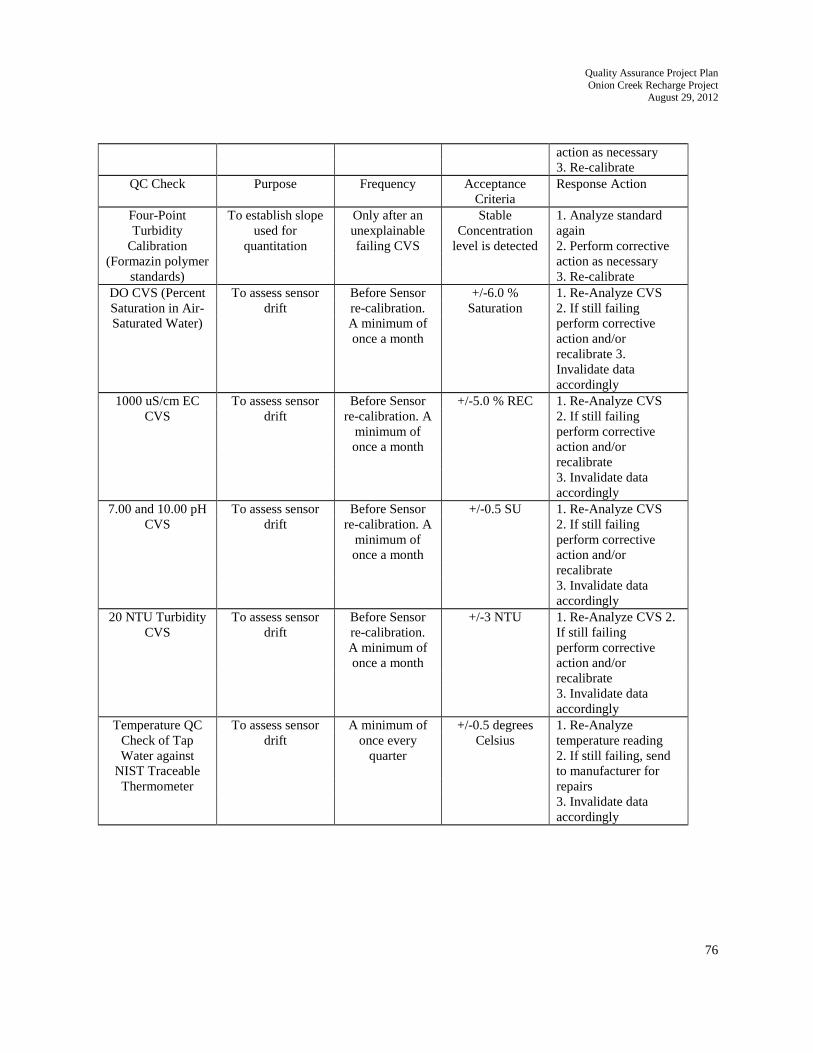
Quality Assurance Project Plan
Onion Creek Recharge Project August 29, 2012
76
action as necessary
3. Re-calibrate
QC Check Purpose Frequency Acceptance
Criteria
Response Action
Four-Point To establish slope Only after an Stable 1. Analyze standard
Turbidity used for unexplainable Concentration again
Calibration quantitation failing CVS level is detected 2. Perform corrective
(Formazin polymer action as necessary
standards) 3. Re-calibrate
DO CVS (Percent To assess sensor Before Sensor +/-6.0 % 1. Re-Analyze CVS
Saturation in Air- drift re-calibration. Saturation 2. If still failing
Saturated Water) A minimum of
once a month
perform corrective
action and/or
recalibrate 3.
Invalidate data
accordingly
1000 uS/cm EC To assess sensor Before Sensor +/-5.0 % REC 1. Re-Analyze CVS
CVS drift re-calibration. A
minimum of
2. If still failing
perform corrective
once a month action and/or
recalibrate
3. Invalidate data
accordingly
7.00 and 10.00 pH To assess sensor Before Sensor +/-0.5 SU 1. Re-Analyze CVS
CVS drift re-calibration. A
minimum of
2. If still failing
perform corrective
once a month action and/or
recalibrate
3. Invalidate data
accordingly
20 NTU Turbidity
CVS
To assess sensor
drift
Before Sensor
re-calibration.
+/-3 NTU 1. Re-Analyze CVS 2.
If still failing
A minimum of perform corrective
once a month action and/or
recalibrate
3. Invalidate data
accordingly
Temperature QC To assess sensor A minimum of +/-0.5 degrees 1. Re-Analyze
Check of Tap drift once every Celsius temperature reading
Water against quarter 2. If still failing, send
NIST Traceable to manufacturer for
Thermometer repairs
3. Invalidate data
accordingly

Quality Assurance Project Plan
Onion Creek Recharge Project August 29, 2012
77
10.0 Definitions
10.1 CVS -Calibration Verification Sample
10.2 uS/cm = micro Siemens per centimeter (unit of electrical conductance)
10.3 DO= Dissolved Oxygen
10.4 NTU = Nephelometric Turbidity Units (unit of turbidity)
10.5 mg/l – milligrams per liter (unit of concentration)
10.6 SU – Standard Units (units of pH measurement)
11.0 References
In-Situ Inc. Multi-Parameter TROLL 9500, WQP-100, Operator’s Manual
Surface Water Quality Monitoring Procedures Manual, Volume I
Continuous Water Quality Monitoring Network Quality Assurance Project Plan, March 2012
12.0 Pollution Prevention and Waste Management
Supervisors, sampling personnel, and laboratory analysts should identify and implement innovative and
cost saving water reduction procedures as part of the method development, review, and revision of
standard operating procedures. Wastes that result from these procedures are managed and disposed of in
accordance with appropriate state and federal regulations.
The Reagents, washes, standards, and waste associated with this procedure do not require special
disposal. Before disposing waste into a municipal sewer system check with respective municipal sewer
system on what concentration levels are allowed to be put into their system.
13.0 Shorthand Procedure
Setup Procedures (Section 7.1 and 7.3).
Calibrate EC, DO, and pH sensors once a month at a minimum.
Deploy TROLL
Monitoring and Sensor Verification (Section 7.2 and 7.4).
Monitor TROLLS weekly via the internet if online data is available.
Analyze EC, DO, pH and Turbidity CVSs once a month.
Check TROLL temperature sensors every 3 months with an NIST traceable thermometer.