OneWireless R200 Wireless Device Manager User's … · Honeywell Process Solutions OneWireless...
154
Honeywell Process Solutions OneWireless Wireless Device Manager User's Guide OW-CC0020 R200 May 2011 Release 200 Honeywell
Transcript of OneWireless R200 Wireless Device Manager User's … · Honeywell Process Solutions OneWireless...

Honeywell Process Solutions
OneWireless
Wireless Device Manager User's Guide
OW-CC0020 R200
May 2011
Release 200 Honeywell
ii OneWireless Wireless Device Manager User's Guide R200 Honeywell May 2011
Notices and Trademarks
Copyright 2011 by Honeywell International Sárl. Release 200 May 2011
While this information is presented in good faith and believed to be accurate, Honeywell disclaims the implied warranties of merchantability and fitness for a particular purpose and makes no express warranties except as may be stated in its written agreement with and for its customers.
In no event is Honeywell liable to anyone for any indirect, special or consequential damages. The information and specifications in this document are subject to change without notice.
Honeywell, PlantScape, Experion PKS, and TotalPlant are registered trademarks of Honeywell International Inc.
Other brand or product names are trademarks of their respective owners.
Honeywell Process Solutions
1860 W. Rose Garden Lane
Phoenix, AZ 85027 USA
1-800 822-7673

R200 OneWireless Wireless Device Manager User's Guide iii May 2011 Honeywell
About This Document This document describes the procedures to provision, configure, operate, and monitor an ISA100.11a wireless field device network using the Wireless Device Manager.
Release Information
Document Name Document ID
Release Number
Publication Date
Wireless Device Manager User's Guide - wdmug OW-CC0020
200 May 2011
Document Category
Installation and Upgrades
References The following list identifies all the documents that may be sources of reference for material discussed in this publication.
Document Title
OneWireless R200 Release Notes
OneWireless R200 Network Planning and Installation Guide
OneWireless R200 Field Device Access Point User’s Guide
OneWireless R200 Multinode User’s Guide

Terms and abbreviations
iv OneWireless Wireless Device Manager User's Guide R200 Honeywell May 2011
Terms and abbreviations This section contains a collection of special terms and abbreviations used in this document.
Terms Definition
Access Point Entity responsible for the receipt of data packets from the ISA100.11a wireless field device network.
Backbone A backbone network is a part of the network infrastructure that interconnects various components of a network, providing a path for the exchange of information between different LANs or sub networks.
CRC Cyclic Redundancy Check
DD files Device Description files
DHCP Server Dynamic Host Configuration Protocol (DHCP) server assigns IP addresses to devices that join the network, from the range of IP addresses assigned to it during the configuration.
DSSS Direct Sequence Spread Spectrum
FDAP Field Device Access Point (FDAP) is a wireless infrastructure node that acts as an ISA100.11a access point and a mesh node member. FDAP can only communicate through ISA100.11a.
FDN Field Device Network
Field device A general term for process sensor (input) or process actuator (output) device.
HART Highway Addressable Remote Transducer
LAN Local Area Network
Multinode Multinode is an industrial IEEE 802.11a/b/g based access point providing Wi-Fi and ISA100.11a wireless coverage.
PCN Plant Control Network
Provisioning Device handheld
Includes Personal Digital Assistant (PDA), mobile PCs, and so on.
RSQI Receive Signal Quality Index
Terms and abbreviations
R200 OneWireless Wireless Device Manager User's Guide v May 2011 Honeywell
Terms Definition
RSSI Receive Signal Strength Index
WDM Wireless Device Manager manages the ISA100.11a wireless field device network and all the ISA100.11a components connected to the OneWireless network.

Support and Other Contacts
vi OneWireless Wireless Device Manager User's Guide R200 Honeywell May 2011
Support and Other Contacts
United States and Canada Contact:
Phone: Fascimile: Mail:
Honeywell Global TAC - Americas 1-800-822-7673 Calls are answered by dispatcher between 6:00 am and 4:00 pm Mountain Standard Time. Emergency calls outside normal working hours are received by an answering service and returned within one hour. 1-973-455-5000 Honeywell TAC, MS L17 1860 W. Garden Lane Phoenix, AZ, 85027 USA
Europe, Middle East, and Africa (EMEA) Contact:
Phone: Fascimile: Mail:
Honeywell Global TAC-EMEA +32-2-728-2345 +32-2-728-2696 TAC-BE02 Hermes Plaza Hermeslaan, 1H B-1831 Diegem, Belgium
Pacific Contact:
Phone: Fascimile: Mail: Email:
Honeywell Global TAC – Pacific 1300-364-822 (toll free within Australia) +61-8-9362-9559 (outside Australia) +61-8-9362-9564 Honeywell Limited Australia 5 Kitchener Way Burswood 6100, Western Australia [email protected]
India Contact:
Phone: Fascimile: Mail: Email:
Honeywell Global TAC – India +91-20- 6603-9400 +91-20- 6603-9800 Honeywell Automation India Ltd 56 and 57, Hadapsar Industrial Estate Hadapsar, Pune –411 013, India [email protected]

Support and Other Contacts
R200 OneWireless Wireless Device Manager User's Guide vii May 2011 Honeywell
Korea Contact:
Phone: Fascimile: Mail: Email:
Honeywell Global TAC – Korea +82-2-799-6317 +82-2-792-9015 Honeywell Co., Ltd 4F, Sangam IT Tower 1590, DMC Sangam-dong, Mapo-gu Seoul, 121-836, Korea [email protected]
People’s Republic of China Contact:
Phone: Mail: Email:
Honeywell Global TAC – China +86- 21-2219-6888 800-820-0237 400-820-0386 Honeywell (China) Co., Ltd 33/F, Tower A, City Center, 100 Zunyi Rd. Shanghai 200051, People’s Republic of China [email protected]
Singapore Contact:
Phone: Fascimile: Mail: Email:
Honeywell Global TAC – South East Asia +65-6580-3500 +65-6580-3501 +65-6445-3033 Honeywell Private Limited Honeywell Building 17, Changi Business Park Central 1 Singapore 486073 [email protected]
Taiwan Contact:
Phone: Fascimile: Mail: Email:
Honeywell Global TAC – Taiwan +886-7-536-2567 +886-7-536-2039 Honeywell Taiwan Ltd. 17F-1, No. 260, Jhongshan 2nd Road. Cianjhen District Kaohsiung, Taiwan, ROC [email protected]

Support and Other Contacts
viii OneWireless Wireless Device Manager User's Guide R200 Honeywell May 2011
Japan Contact:
Phone: Fascimile: Mail: Email:
Honeywell Global TAC – Japan +81-3-6730-7160 +81-3-6730-7228 Honeywell Japan Inc. New Pier Takeshiba, South Tower Building, 20th Floor, 1-16-1 Kaigan, Minato-ku, Tokyo 105-0022, Japan [email protected]
Elsewhere Call your nearest Honeywell office.
World Wide Web Honeywell Solution Support Online:
http://www.honeywell.com/ps
Training Classes Honeywell Automation College:
http://www.automationcollege.com

Symbol Definitions
R200 OneWireless Wireless Device Manager User's Guide ix May 2011 Honeywell
Symbol Definitions The following table lists those symbols used in this document to denote certain conditions.
Symbol Definition
ATTENTION: Identifies information that requires special consideration.
TIP: Identifies advice or hints for the user, often in terms of performing a task.
REFERENCE -EXTERNAL: Identifies an additional source of information outside of the bookset.
REFERENCE - INTERNAL: Identifies an additional source of information within the bookset.
CAUTION
Indicates a situation which, if not avoided, may result in equipment or work (data) on the system being damaged or lost, or may result in the inability to properly operate the process.
CAUTION: Indicates a potentially hazardous situation which, if not avoided, may result in minor or moderate injury. It may also be used to alert against unsafe practices.
CAUTION symbol on the equipment refers the user to the product manual for additional information. The symbol appears next to required information in the manual.
WARNING: Indicates a potentially hazardous situation, which, if not avoided, could result in serious injury or death.
WARNING symbol on the equipment refers the user to the product manual for additional information. The symbol appears next to required information in the manual.

Symbol Definitions
x OneWireless Wireless Device Manager User's Guide R200 Honeywell May 2011

R200 OneWireless Wireless Device Manager User's Guide xi May 2011 Honeywell
Contents
1. INTRODUCTION .......................................................................... 17 1.1 Overview of Wireless Device Manager ....................................................... 17
What is Wireless Device Manager? ..................................................................................... 17 Functions of WDM ................................................................................................................ 17 Hardware description of WDM ............................................................................................. 19
1.2 About OneWireless user interface .............................................................. 21
1.3 Overview of OneWireless Network setup ................................................... 22
2. GETTING STARTED WITH WDM ................................................ 23 2.1 Configuring network properties on the computer ..................................... 23
2.2 Installing the WDM ........................................................................................ 24 Establish physical connection between WDM and Multinode............................................... 24 Establish physical connection between WDM and FDAP .................................................... 24 Establish physical connection between WDM and a computer ............................................ 25 Power up the components.................................................................................................... 25
2.3 Logging on to OneWireless user interface ................................................. 26
2.4 Configuring WDM using the First time Configuration Wizard .................. 27
2.5 Migrating from Onewireless R120 ............................................................... 35
2.6 Understanding the OneWireless user interface ......................................... 43 Navigation panel .................................................................................................................. 44 About map view .................................................................................................................... 46 Selection Panel .................................................................................................................... 49 Understand the device icons ................................................................................................ 54 Property Panel ..................................................................................................................... 55 Status bar ............................................................................................................................. 58
3. CONFIGURATION ....................................................................... 59 3.1 Configuring a Provisioning Device handheld ............................................ 59
Install synchronization software on the computer ................................................................. 59 Install Microsoft .NET Compact Framework 3.5 on the Provisioning Device handheld ........ 59 Install Provisioning Device Application on the Provisioning Device handheld ...................... 61 Generate and transfer the provisioning keys to the Provisioning Device handheld .............. 64 Remove Provisioning Device handheld ................................................................................ 66

Contents
xii OneWireless Wireless Device Manager User's Guide R200 Honeywell May 2011
3.2 Loading the Device Description file ............................................................. 67
3.3 Provisioning the OneWireless Network components ................................ 68 Provision an FDAP/Multinode/field device ........................................................................... 68
3.4 Configuring the WDM .................................................................................... 70 Configure WDM properties .................................................................................................. 70 Configure default routing policy ........................................................................................... 70 Configure key rotation period .............................................................................................. 72
3.5 Configuring field devices .............................................................................. 73 Configure field device properties ......................................................................................... 73 Configure routing assignment ............................................................................................. 73 Configure publication rate and stale limit ............................................................................. 74 Calibrate field devices ......................................................................................................... 76
3.6 Configuring field device channels ............................................................... 80 Configure Mode and Scale .................................................................................................. 80 Add channels to publication groups ..................................................................................... 81 Configure channel instantiation ........................................................................................... 82 Remove channels from publication groups ......................................................................... 85 Delete (uninstantiate) channels ........................................................................................... 85
3.7 Adding notes for devices .............................................................................. 86
4. OPERATIONS ............................................................................. 87 4.1 Setting up the monitoring area .................................................................... 87
About location-specific monitoring ....................................................................................... 87 Configure site locations ....................................................................................................... 88 Position the devices on the map .......................................................................................... 89
4.2 Configuring alerts for field devices ............................................................. 90
4.3 Verifying connectivity using maps .............................................................. 91
4.4 Monitoring the network and devices ........................................................... 92
4.5 Monitoring alarms and events ...................................................................... 95
4.6 Viewing license agreement files .................................................................. 98
5. ACTIVATE PROCESS CONTROL INTERFACES ...................... 99 5.1 Establishing connection between WDM and external interfaces ............. 99
5.2 Activating HART in OneWireless Network .................................................. 99 Configure HART serial interface .......................................................................................... 99 Monitor performance of HART interface ............................................................................ 102 Monitor field devices from an asset management system ................................................. 103

Contents
R200 OneWireless Wireless Device Manager User's Guide xiii May 2011 Honeywell
5.3 Activating Modbus in Onewireless Network ............................................ 106 Prerequisite ........................................................................................................................ 107
5.4 Activating OPC in OneWireless Network .................................................. 112 Configure OPC UA client system ....................................................................................... 112 Install OPC proxies ............................................................................................................ 118 Configure Classic OPC client system ................................................................................. 120 Monitor OPC Interface statistics ......................................................................................... 125
6. ADMINISTRATION ..................................................................... 127 6.1 Administering users ................................................................................... 127
About users and user roles ................................................................................................ 127 Create user accounts ......................................................................................................... 127 Change password .............................................................................................................. 128 Reset password ................................................................................................................. 129 Delete user account ........................................................................................................... 129 Change user role ................................................................................................................ 130
6.2 Upgrading device firmware ........................................................................ 131 Upgrade the WDM firmware ............................................................................................... 131 Upgrade the FDAP/Multinode firmware .............................................................................. 132 Upgrade the field device firmware ...................................................................................... 135
6.3 Configuring system configuration backup ............................................... 138 About system configuration backup ................................................................................... 138 Configure manual backup .................................................................................................. 139 Configure automatic backup ............................................................................................... 140
6.4 Restoring the system configuration from a backup ................................ 141
7. TROUBLESHOOTING AND MAINTENANCE ........................... 143 7.1 Replacing devices ....................................................................................... 143
7.2 Removing devices ....................................................................................... 146
7.3 Resetting/removing a WDM ........................................................................ 147
7.4 Restarting FDAPs/Multinodes/field devices ............................................. 149
7.5 Generating reports ...................................................................................... 150
7.6 Exporting and saving system logs ............................................................ 151
7.7 Reporting anomalies ................................................................................... 152

ContentsTables
xiv OneWireless Wireless Device Manager User's Guide R200 Honeywell May 2011
Tables Table 1 WDM roles and functions .................................................................................. 17 Table 2 Description of WDM ports ................................................................................. 20 Table 3 Navigation panel elements ................................................................................ 44 Table 4 Map navigation controls .................................................................................... 47 Table 5 Field device performance indicators ................................................................. 49 Table 6 Selection Panel elements .................................................................................. 51 Table 7 Device state icons ............................................................................................. 54 Table 8 Property Panel elements ................................................................................... 57 Table 9 Status bar panes ............................................................................................... 58 Table 10 Device attributes in the tabular view ............................................................... 93 Table 11 Channel attributes in the tabular view ............................................................. 94

ContentsFigures
R200 OneWireless Wireless Device Manager User's Guide xv May 2011 Honeywell
Figures Figure 1 WDM hardware ................................................................................................ 19 Figure 2 OneWireless user interface ............................................................................. 43 Figure 3 Map view ......................................................................................................... 46 Figure 4 Selection Panel................................................................................................ 50 Figure 5 Tabular view of the Selection Panel ................................................................ 52 Figure 6 Tabular view with radio details of the devices ................................................. 53 Figure 7 WDM Property Panel ....................................................................................... 56 Figure 8 Location-specific monitoring ............................................................................ 87 Figure 9 Monitoring the network using the tabular view ................................................ 92 Figure 10 Modbus TCP communication ...................................................................... 106 Figure 11 Modbus RTU communication ...................................................................... 107 Figure 12 OPC Interface .............................................................................................. 112 Figure 13 OPC client with Classic OPC ...................................................................... 118

Contents
xvi OneWireless Wireless Device Manager User's Guide R200 Honeywell May 2011

R200 OneWireless Wireless Device Manager User's Guide 17 May 2011 Honeywell
1. Introduction
1.1 Overview of Wireless Device Manager What is Wireless Device Manager?
Wireless Device Manager (WDM) is the central management unit of a single ISA100.11a wireless field device network. It allows you to implement and monitor the ISA100.11a wireless field device network using an HTTP-based user interface. The WDM also supports integration with external control systems using industry standard protocols, such as Modbus TCP, Modbus RTU, HART, and OPC.
Functions of WDM
OneWireless Network is complaint with ISA100.11a standard. As a component of the OneWireless Network, the following are the WDM ISA00.11a roles and functions.
Table 1 WDM roles and functions
Role Functions
Gateway • Acts as the communication interface for the wireless field devices.
• Provides wireless field device data cache for the OneWireless user interface and the external control systems.
• Allows communication between wired HART devices with OneWireless Adapter and the asset management system.
System Manager • Manages the ISA100.11a field device network and the devices.
• Establishes communication between the devices.
• Performs policy-based control of the network runtime configuration.
• Monitors and reports the communication configuration, performance, and operational status.
1. Introduction 1.1. Overview of Wireless Device Manager
18 OneWireless Wireless Device Manager User's Guide R200 Honeywell May 2011
Role Functions
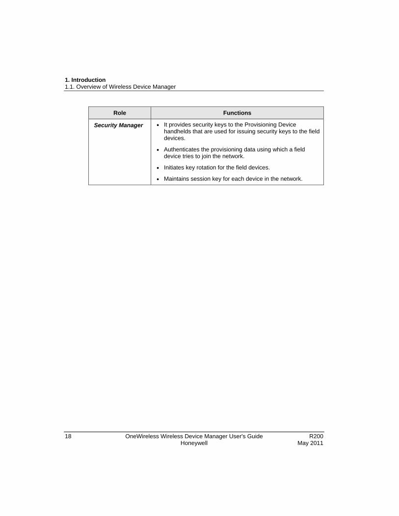
Security Manager • It provides security keys to the Provisioning Device handhelds that are used for issuing security keys to the field devices.
• Authenticates the provisioning data using which a field device tries to join the network.
• Initiates key rotation for the field devices.
• Maintains session key for each device in the network.

1. Introduction 1.1. Overview of Wireless Device Manager
R200 OneWireless Wireless Device Manager User's Guide 19 May 2011 Honeywell
Hardware description of WDM
Figure 1 WDM hardware

1. Introduction 1.1. Overview of Wireless Device Manager
20 OneWireless Wireless Device Manager User's Guide R200 Honeywell May 2011
Table 2 Description of WDM ports
Port name Description
Field Device Network (FDN) port Used for connecting the WDM with FDAPs/Multinodes.
ATTENTION
The FDN port is also known as the “FIN – Field Instrument Network” port in some WDMs.
Plant Control Network (PCN) port Used for connecting the monitoring clients and external controllers.
ATTENTION
The WDM contains an embedded firewall that restricts the data routing between the two network ports.
COM ports The WDM has three serial ports, two of which can be used as standard RS232 ports and the third port can be used as an RS485 port.
USB ports Used for connecting USB flash drives.
For more information about the technical specifications of the WDM, refer to the specifications document available at http://hpsweb.honeywell.com/Cultures/en-US/Products/Wireless/SecondGenerationWireless/Literature/documents.htm.
1. Introduction 1.2. About OneWireless user interface
R200 OneWireless Wireless Device Manager User's Guide 21 May 2011 Honeywell
1.2 About OneWireless user interface The WDM provides an HTTP-based user interface for configuring and monitoring all the devices connected to the ISA100.11a wireless field device network. To start managing the ISA100.11a wireless field device network, you first need to configure the WDM. When you access the OneWireless user interface for the first time, the WDM needs to be configured using the First Time Configuration Wizard. After that, you can use the user interface for provisioning, commissioning, configuring, monitoring, and decommissioning of the Field Device Access Points (FDAP), Multinodes, and field devices.
In addition, the user interface can be used for performing the following tasks.
• Network maintenance
• Security configuration
• Device configuration and maintenance
• Operator activities
The following are some of the benefits of OneWireless user interface.
• Requires no installation
• Is simple and easy to use
• Reduces commissioning time
• Reduces security threats with secured HTTPS-based user interface
• Provides simultaneous access to WDM using multiple logon sessions
• Supports device diagnostics summary display and related reports capability
• Supports effective node failure diagnosis
• Simplifies integration of the wireless field devices with process control interfaces

1. Introduction 1.3. Overview of OneWireless Network setup
22 OneWireless Wireless Device Manager User's Guide R200 Honeywell May 2011
1.3 Overview of OneWireless Network setup Setup the OneWireless Network in the following sequence.
1. Install and configure the WDM.
2. Power up and provision all the Multinodes/FDAPs as access points.
3. Confirm that all the access points (that have ISA100.11a wireless field device network visibility to each other) have formed links with each other. You may have to power-cycle one or more access points to allow them to form a single field device network.
4. Power up and provision all the FDAPs as routers.
5. Power up and provision all the routing field devices.
6. Power up and provision all the field devices.

R200 OneWireless Wireless Device Manager User's Guide 23 May 2011 Honeywell
2. Getting started with WDM
2.1 Configuring network properties on the computer
Prerequisites
• A desktop or a laptop computer for accessing the OneWireless user interface.
ATTENTION
The steps in the following procedure are specific to Microsoft Windows XP operating system.
Step Action
1 Perform one of the following steps to open the Network Connections dialog box.
• Choose Start > Settings > Network Connections.
Or
• Choose Start > Control Panel > Network Connections.
2 Right-click the network port connected to the WDM and click Properties.
3 On the General tab, select Internet Protocol (TCP/IP) check box, and then click Properties.
ATTENTION
Note down the current settings in Internet Protocol (TCP/IP) Properties so that, if necessary, you can return to their original values.
4 Type the IP address as 192.168.1.x and the Subnet Mask as 255.255.255.0.
5 Click OK to close the Internet Protocol (TCP/IP) Properties dialog box.
6 Click OK and close all the dialog boxes.

2. Getting started with WDM 2.2. Installing the WDM
24 OneWireless Wireless Device Manager User's Guide R200 Honeywell May 2011
2.2 Installing the WDM
Prerequisites
• Ensure that you have a maximum power requirement of 48 W (10 ~ 36 VDC).
• Ensure that you have an FDN Ethernet switch when connecting multiple FDAPs/Multinodes to the WDM.
• You have Ethernet cables required for connecting the devices.
• Identify the location for mounting the devices.
Establish physical connection between WDM and Multinode
Step Action
1 Connect the Ethernet cable from the Multinode to the WDM FDN port.
OR
If you are using multiple Multinodes, you can use an Ethernet switch to connect the Multinodes to the WDM. You can also configure the Multinode's IEEE 802.11a/b/g to communicate with a Multinode that is physically connected to the WDM or to the FDN Ethernet switch.
For more information about installing a Multinode, refer to the Multinode User’s Guide.
Establish physical connection between WDM and FDAP
Step Action
1 Connect the Ethernet cable from the FDAP to the WDM FDN port.
OR
If you are using multiple FDAPs, you can use an Ethernet switch to connect the FDAPs to the WDM.
OR
Connect the Ethernet cable from the FDAP to one end of the RJ-45 Ethernet cable labeled WAN1 of the Multinode.
For more information about installing and setting up the FDAP, refer to the Field Device Access Point User’s Guide.

2. Getting started with WDM 2.2. Installing the WDM
R200 OneWireless Wireless Device Manager User's Guide 25 May 2011 Honeywell
Step Action
ATTENTION
The WDM has the capability to act as the DHCP Server for the network. However, if you are configuring an external DHCP Server for the network, ensure you connect the DHCP Server to the switch during this stage.
Establish physical connection between WDM and a computer
Step Action
1 Connect the WDM power cable to a DC power supply.
2 Connect the Ethernet cable from the computer’s network port to the WDM PCN port or to a switch connected to the PCN port.
Power up the components
Step Action
1 After establishing connection with the WDM, power up the WDM, FDAPs, and Multinodes.
ATTENTION
When powering up the WDM, if a duplicate IP address is configured on either the PCN port or the FDN port, the WDM startup operation ends and no IP address is assigned. To recover, you must resolve the duplicate IP address and then power-cycle the WDM.

2. Getting started with WDM 2.3. Logging on to OneWireless user interface
26 OneWireless Wireless Device Manager User's Guide R200 Honeywell May 2011
2.3 Logging on to OneWireless user interface
Prerequisites
• One of the following recommended Web browsers must be installed on the computer.
− Microsoft Internet Explorer 6.0, 7.0 or 8.0
− Firefox 3.6 or higher
Perform the following steps to log on to the OneWireless user interface.
Step Action
1 Open the Web browser and type the URL for the WDM in the address bar.
If you are logging on to the user interface for the first time, type the default address as https://192.168.1.1.
2 If a security warning appears, confirm or allow the security exception.
3 Type the User ID and Password, and then click Login.
ATTENTION
The default User ID and Password configured for the WDM are as follows:
User ID: administrator Password: password
Note that the User ID and Password are case-sensitive.

2. Getting started with WDM 2.4. Configuring WDM using the First time Configuration Wizard
R200 OneWireless Wireless Device Manager User's Guide 27 May 2011 Honeywell
2.4 Configuring WDM using the First time Configuration Wizard
After installing the WDM, you need to configure the WDM to enable it to function in the R200 network. The First Time Configuration Wizard guides you through the initial configuration of the WDM. The First Time Configuration Wizard appears ONLY when you log on to the OneWireless user interface for the first time.
Considerations
The following are some of the network configuration rules that you must follow while configuring the network properties.
• FDN and PCN must be on separate subnets.
• FDN IP address must be outside the FDAP IP address range.
• FDN subnet mask must include FDN IP address and FDAP IP address range.
• Default PCN gateway must be on the same subnet as PCN.
ATTENTION
If you are performing a migration from R120 to R200, skip this section and proceed to the section Migrating from Onewireless R120.
Step Action
1 Log on to the OneWireless user interface using the default User ID and Password.
The First Time Configuration Wizard appears.
2 On the Welcome page of the First Time Configuration Wizard, click Next.

2. Getting started with WDM 2.4. Configuring WDM using the First time Configuration Wizard
28 OneWireless Wireless Device Manager User's Guide R200 Honeywell May 2011
Step Action
3 On the Wireless Device Manager Configuration page, click Configure New Wireless Device Manager and click Next.
2. Getting started with WDM 2.4. Configuring WDM using the First time Configuration Wizard
R200 OneWireless Wireless Device Manager User's Guide 29 May 2011 Honeywell
Step Action
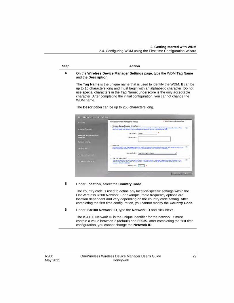
4 On the Wireless Device Manager Settings page, type the WDM Tag Name and the Description.
The Tag Name is the unique name that is used to identify the WDM. It can be up to 16 characters long and must begin with an alphabetic character. Do not use special characters in the Tag Name; underscore is the only acceptable character. After completing the initial configuration, you cannot change the WDM name.
The Description can be up to 255 characters long.
5 Under Location, select the Country Code.
The country code is used to define any location-specific settings within the OneWireless R200 Network. For example, radio frequency options are location dependent and vary depending on the country code setting. After completing the first time configuration, you cannot modify the Country Code.
6 Under ISA100 Network ID, type the Network ID and click Next.
The ISA100 Network ID is the unique identifier for the network. It must contain a value between 2 (default) and 65535. After completing the first time configuration, you cannot change the Network ID.

2. Getting started with WDM 2.4. Configuring WDM using the First time Configuration Wizard
30 OneWireless Wireless Device Manager User's Guide R200 Honeywell May 2011
Step Action
7 On the Network Settings page, under Field Device Network (FDN) enter the following information to configure the network settings for the wireless field device network.
• Field Device Network IP Address: These settings are used to configure
the wireless field device network Ethernet connection for the WDM. This is used for communication with FDAP and field devices.
Note: After completing the initial configuration, you cannot change the Field Device Network IP Address specified in the First Time Configuration Wizard.
• Subnet Mask: A subnet mask identifies the bits of an IP address that are reserved for the network address. For example, if the IP address of a particular node is 192.168.2.3 with a subnet mask of 255.255.255.0, the subnet mask indicates that the first 24 bits of the address represent the network address. The last 8 bits can be used for individual node addresses on that network.
• Assign Addresses to Field Device Access Points (Enable DHCP Server): Select this check box to enable the WDM to act as the DHCP Server. Ensure you do not select the check box if the network has another DHCP Server. It is recommended to enable the WDM to act as the DHCP Server.

2. Getting started with WDM 2.4. Configuring WDM using the First time Configuration Wizard
R200 OneWireless Wireless Device Manager User's Guide 31 May 2011 Honeywell
Step Action
• Field Device Access Point IP Address: This option is enabled only if you have selected the Enable DHCP Server check box. Accept the default range or enter the IP address range according to the network settings in the plant network. The WDM that acts as the DHCP Server assigns IP addresses based on the range specified. Ensure that the IP addresses of the Multinodes are not within the DHCP address range.
If you do not enable DHCP Server during the first time configuration, it is possible to enable this at a later stage using the Property Panel.
8 Under Process Control Network (PCN), enter the following information to configure the process control network.
• Process Control Network IP Address: The process control network settings are used to configure the process control network Ethernet connections for the WDM. This is used for communication with monitoring applications and external controllers.
• Subnet Mask
• Default gateway: Used to access the subnets outside the PCN subnet. This is an optional configuration option.
9 Click Next.
The Network Time page appears.

2. Getting started with WDM 2.4. Configuring WDM using the First time Configuration Wizard
32 OneWireless Wireless Device Manager User's Guide R200 Honeywell May 2011
Step Action
10 Click Use NTPServer or Use System Time based on your selection.
You can use either the NTP server or system time to configure the network time of the OneWireless Network.
ATTENTION
• By default, the network time is configured as the system time.
• Consider the following while configuring an external NTP server.
− NTP server should be on the PCN or FDN.
− NTP server IP address must be within FDN or PCN subnet unless a default gateway has been configured on the PCN subnet and the NTP server is accessible through the default gateway.
− NTP server IP address should not overlap with the FDN and PCN IP addresses.
− NTP server IP address should not overlap with FDAP IP address range, if DHCP Server is enabled.
11 If you are selecting NTP server, enter the NTP Server IP Address and click Next.
The Administrator Information page appears.

2. Getting started with WDM 2.4. Configuring WDM using the First time Configuration Wizard
R200 OneWireless Wireless Device Manager User's Guide 33 May 2011 Honeywell
Step Action
12 Type the new Administrator password in the New Password and Confirm Password fields, and then click Next.
The password must contain at least one character and can contain up to 32 characters. It should not start or end with a space and must not contain single quote (‘).
The Configuration Summary page appears which contains the summary of all the configuration information specified in the First Time Configuration Wizard. An incorrect entry is indicated by a warning icon. Hovering the mouse over the icon displays a tooltip with the information about the incorrect entry.
13 Verify the WDM settings, correct errors if any, and then click Finish.
If there are any errors in the configuration information that you have provided, then the system does not allow you to click Finish.
14 On the Browser Redirect dialog box, click OK.
The wizard redirects the Web browser to the revised process control network IP address.
2. Getting started with WDM 2.4. Configuring WDM using the First time Configuration Wizard
34 OneWireless Wireless Device Manager User's Guide R200 Honeywell May 2011
Step Action
ATTENTION
• If you are configuring the WDM to use the same process control network IP address, then the wizard redirects the Web browser.
• If you have configured the WDM using a different IP address, then you need to reconfigure the network settings of the computer to access the user interface using the new IP address.

2. Getting started with WDM 2.5. Migrating from Onewireless R120
R200 OneWireless Wireless Device Manager User's Guide 35 May 2011 Honeywell
2.5 Migrating from Onewireless R120
Prerequisites
• Ensure that you have reviewed the migration planning information in the Network Planning and Installation Guide.
• Ensure that you have the required security key information that you have exported from the R120 Key Server. For more information about exporting the security key from R120 Key Server, refer to the Network Planning and Installation Guide.
• Use the checklist provided in the Network Planning and Installation Guide while performing the migration. Ensure that you perform all the tasks in the order in which they are documented in the checklist.
Step Action
1 Log on to the OneWireless user interface using the default user name and password. For more information, refer to the section Logging on to OneWireless user interface.
The First Time Configuration Wizard appears.
2 On the Welcome page of the First Time Configuration Wizard, click Next.
The Wireless Device Manager Configuration page appears.

2. Getting started with WDM 2.5. Migrating from Onewireless R120
36 OneWireless Wireless Device Manager User's Guide R200 Honeywell May 2011
Step Action
3 Click Migrate From OneWireless R120 and click Next.
The Migrate from OneWireless R120 page appears.
4 Under Select File From Location, click Browse and navigate to the location where the XML file containing the security key is saved.

2. Getting started with WDM 2.5. Migrating from Onewireless R120
R200 OneWireless Wireless Device Manager User's Guide 37 May 2011 Honeywell
Step Action
5 Select the XML file and click Open, and then click Migrate.
The security keys are imported into the WDM’s Security Manager and a security configuration migrated message appears.
6 Click Next.
The Wireless Device Manager Settings page appears.

2. Getting started with WDM 2.5. Migrating from Onewireless R120
38 OneWireless Wireless Device Manager User's Guide R200 Honeywell May 2011
Step Action
7 Under Wireless Device Manager Identification, type the Tag Name and Description.
The Tag Name is the unique name that is used to identify the WDM. It can be up to 16 characters long and must start with an alphabetic character. Do not use special characters in the Tag Name; underscore is the only acceptable character. After completing the initial configuration, you cannot change the WDM name.
The Description can be up to 255 characters long.
8 Under Location, select the Country Code.
The Country code is used to present any location-specific settings within the OneWireless Network. For example, radio frequency options are location dependent and vary depending on the country code setting. After completing the first time configuration, you cannot modify the Country Code.
9 Under ISA100 Network ID, the Network ID appears by default. This information is imported from the security file that you have exported from the R120 Key Server.
10 Click Next.
The Network Settings page appears.

2. Getting started with WDM 2.5. Migrating from Onewireless R120
R200 OneWireless Wireless Device Manager User's Guide 39 May 2011 Honeywell
Step Action
11 Under Field Device Network (FDN), enter the following information to configure the network settings for wireless field device network. The FDN connects the WDM with one or more FDAPs.
• Field Device Network IP Address: This is used to configure the wireless field device network Ethernet connection for the WDM. This is used for communication with FDAPs and field devices.
Note: After completing the initial configuration, you cannot change the Field Device Network IP Address specified in the First Time Configuration Wizard.
• Subnet Mask
• Assign Addresses to Field Device Access Points (Enable DHCP Server): Select this check box to enable the WDM to act as the DHCP Server. Ensure you do not select the check box if the network has another DHCP Server. It is recommended to enable the WDM to act as the DHCP Server.
• Field Device Access Point IP Address: This option is enabled only if you have selected the Enable DHCP Server check box. Accept the default range or enter the IP address range according to the network settings in the plant network. The WDM that acts as the DHCP Server assigns IP addresses based on the range specified.
If you do not enable DHCP Server during the first time configuration, it is possible to enable this at a later stage using the Property Panel.
12 Under Process Control Network (PCN), enter the following information to configure the process control network.
• Process Control Network IP Address: The process network settings are used to configure the process control network Ethernet connections for the WDM. This is used for communication with monitoring applications and external controllers.
• Subnet Mask
• Default gateway: Used to access the subnets outside the PCN subnet. This is an optional configuration option.

2. Getting started with WDM 2.5. Migrating from Onewireless R120
40 OneWireless Wireless Device Manager User's Guide R200 Honeywell May 2011
Step Action
13 Click Next.
The Network Time page appears.
14 Click Use NTPServer or Use System Time based on your selection.
You can use either the NTP server or the system time to configure the network time of the OneWireless system.
ATTENTION
• By default, the network time is configured as the system time.
• Consider the following while configuring an external NTP server.
− NTP server should be on the PCN or FDN.
− The NTP server IP address should not overlap with the FDN and PCN IP addresses.
− NTP server IP address should not overlap with FDAP IP address range, if DHCP Server is enabled.
− NTP server IP address must be within FDN or PCN subnet, unless a default gateway is configured on the PCN subnet and the NTP server is accessible through the default gateway.
2. Getting started with WDM 2.5. Migrating from Onewireless R120
R200 OneWireless Wireless Device Manager User's Guide 41 May 2011 Honeywell
Step Action
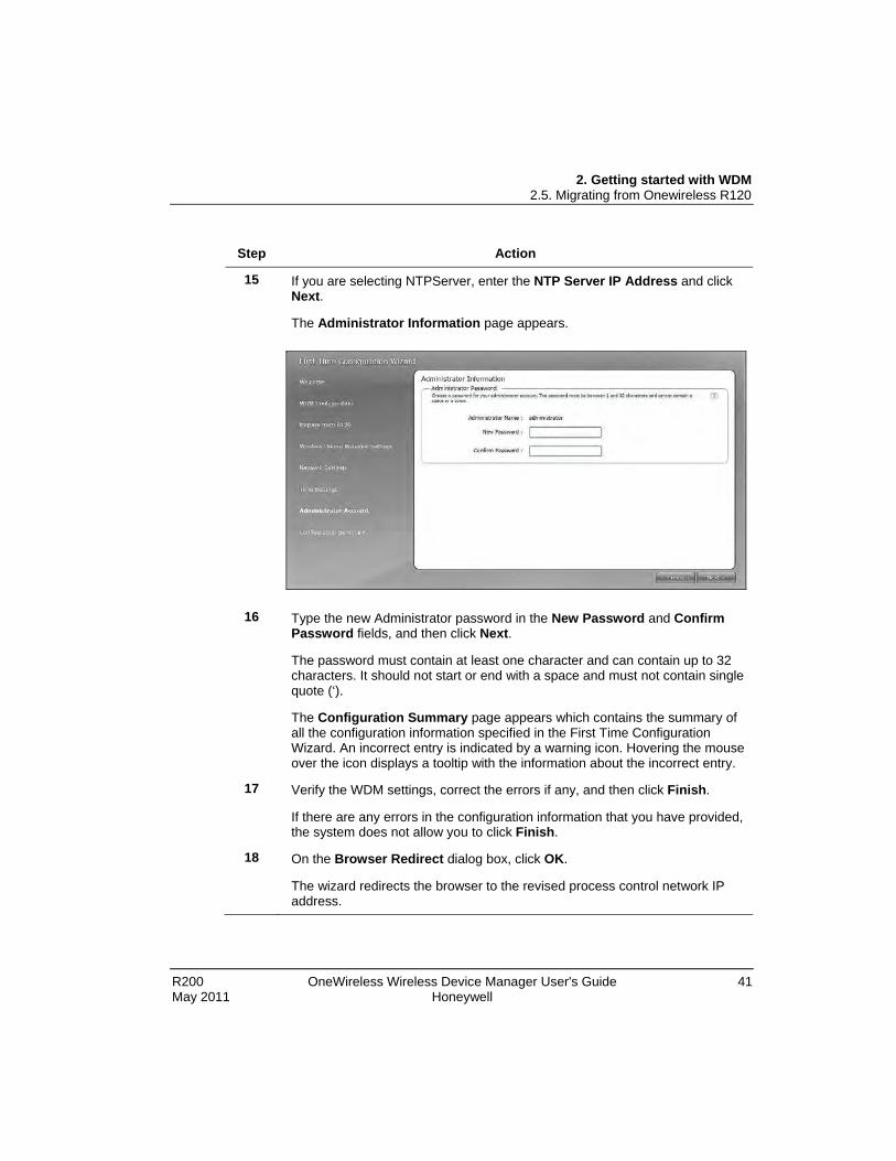
15 If you are selecting NTPServer, enter the NTP Server IP Address and click Next.
The Administrator Information page appears.
16 Type the new Administrator password in the New Password and Confirm
Password fields, and then click Next.
The password must contain at least one character and can contain up to 32 characters. It should not start or end with a space and must not contain single quote (‘).
The Configuration Summary page appears which contains the summary of all the configuration information specified in the First Time Configuration Wizard. An incorrect entry is indicated by a warning icon. Hovering the mouse over the icon displays a tooltip with the information about the incorrect entry.
17 Verify the WDM settings, correct the errors if any, and then click Finish.
If there are any errors in the configuration information that you have provided, the system does not allow you to click Finish.
18 On the Browser Redirect dialog box, click OK.
The wizard redirects the browser to the revised process control network IP address.

2. Getting started with WDM 2.5. Migrating from Onewireless R120
42 OneWireless Wireless Device Manager User's Guide R200 Honeywell May 2011
Step Action
ATTENTION
• If you are configuring the WDM to use the same process control network IP address, then the wizard redirects the Web browser.
• If you have configured the WDM using a different IP address, then you need to reconfigure the network settings of the computer to access the user interface using the new IP address.
19 After completing this task, return to the migration checklist in the Network Planning and Installation Guide.

2. Getting started with WDM 2.6. Understanding the OneWireless user interface
R200 OneWireless Wireless Device Manager User's Guide 43 May 2011 Honeywell
2.6 Understanding the OneWireless user interface After configuring the WDM using the First Time Configuration Wizard, the following OneWireless user interface displays.
Figure 2 OneWireless user interface
OneWireless user interface comprises of the following main elements.
• Navigation panel – Consists of the Monitoring tab, Alarm/Events tab and the Reports tab. It also contains an icon that represent the user who has currently logged on to the user interface and a logout icon.
• Map view – Provides a visual representation of the OneWireless Network.
• Selection Panel – Displays a list of all the devices that are configured in the OneWireless Network.
• Property Panel – Contains configuration properties of all the devices configured in the OneWireless Network.

2. Getting started with WDM 2.6. Understanding the OneWireless user interface
44 OneWireless Wireless Device Manager User's Guide R200 Honeywell May 2011
• Status bar – Provides an overview of the network status by displaying the number of online devices, active alarms, and the progress of any maintenance operation.
The following sections explain each element of the user interface in detail.
Navigation panel The navigation panel in the user interface contains the following tabs and icons.
Table 3 Navigation panel elements
Tab/icon Description
Monitoring tab displays the map view of the OneWireless Network.
Use the Monitoring tab to add, configure, and commission wireless field devices and monitor the devices in a topological view. The topological view of the network is known as the map view. For more information about the map view, refer to the section, About map view.
The Alarm/Events tab displays the alarms and system events generated by the wireless field devices in a tabular format. An alarm is generated whenever an abnormal condition occurs. An event is any significant change in the system, and includes alarms and operator actions. The Alarm/Events tab contains the following sub elements.
• The Active Alarms tab: Lists the devices, device diagnostic alarms and their respective location, source, start time, priority, and description.
• The Alarms/Event History tab: Provides a tabular view of the events. It is possible to export the alarm log and the event log for a particular period.

2. Getting started with WDM 2.6. Understanding the OneWireless user interface
R200 OneWireless Wireless Device Manager User's Guide 45 May 2011 Honeywell
Tab/icon Description
Reports tab displays system/application logs and device performance reports.
Use the Reports tab to generate and view predefined reports that are used to maintain and optimize the network and the field devices. You can also generate and save the system/application logs.
You can generate and view the following reports:
• Battery Life
• Device Health Overview
• Connectivity
The System Logs option enables you to export and save the application log. The application log records information about events in the application instances. The Dump System Logs option allows saving the system logs in a .tar.gz format. This log is used primarily for debugging by Honeywell Technical Assistance Support (TAC).
Displays the user who has currently logged on to the OneWireless user interface.
Click the icon to log out of the OneWireless user interface.
Note that this functionality is currently not supported.

2. Getting started with WDM 2.6. Understanding the OneWireless user interface
46 OneWireless Wireless Device Manager User's Guide R200 Honeywell May 2011
About map view Use the map view to create a visual topology map of the network. The devices can be arranged in a map view according to the plant network topology. The map view allows you to create a real plant topology by dragging and dropping the devices from the device list in the Selection Panel. Arrange the devices on the map according to the plant setup and set the map visibility and overlays such as connection strength and publishing rate. For more information about creating a map view, refer to the section Setting up the monitoring area.
Figure 3 Map view

2. Getting started with WDM 2.6. Understanding the OneWireless user interface
R200 OneWireless Wireless Device Manager User's Guide 47 May 2011 Honeywell
A green line between the devices in the map view indicates strong signal quality, whereas a red line indicates weak signal quality. Solid line between the devices represents an active connection between the devices and a dotted line represents an inactive connection.
The following are the map navigation controls that are available in the map view.
Table 4 Map navigation controls
Map navigation control Description
Indicates the current location. WDM allows you to configure multiple locations to reflect the real plant topology. Click the left and right arrows on the location icon to view multiple locations configured.
You can also view the configured location of a device by double-clicking the device in the Selection Panel.
Pan control is used to move the map in the up, down, left, and right directions. You can also pan the map by clicking and dragging on the map view.
Zoom control used to zoom in or zoom out the map view. You can also use the scroll button on the mouse, to zoom in or zoom out the map view.

2. Getting started with WDM 2.6. Understanding the OneWireless user interface
48 OneWireless Wireless Device Manager User's Guide R200 Honeywell May 2011
Map navigation control Description
Click the icon to view or hide the map. Move the slider down to increase the visibility (fade in) of the map and move the slider up to decrease the visibility (fade out) of the map.
Click to enable or disable the grid lines.
Click to lock or unlock the map view. Locking the map view prevents the devices from being moved on the map. You need to unlock the map view to reposition the devices.
Signal strength icons
Displays the signal strength. Click the icon to display the Receive Signal Quality Index (RSQI) and Receive Signal Strength Index (RSSI) of the network.
Click to hide or display inactive connections.
2. Getting started with WDM 2.6. Understanding the OneWireless user interface
R200 OneWireless Wireless Device Manager User's Guide 49 May 2011 Honeywell
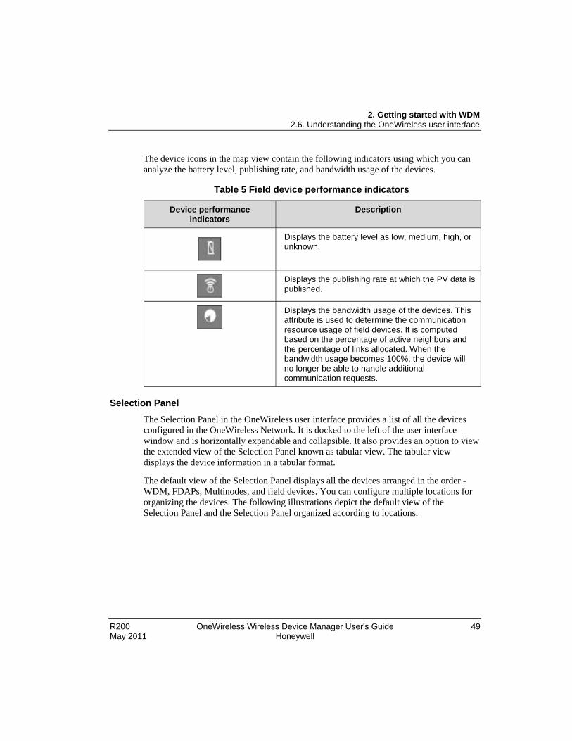
The device icons in the map view contain the following indicators using which you can analyze the battery level, publishing rate, and bandwidth usage of the devices.
Table 5 Field device performance indicators
Device performance indicators
Description
Displays the battery level as low, medium, high, or unknown.
Displays the publishing rate at which the PV data is published.
Displays the bandwidth usage of the devices. This attribute is used to determine the communication resource usage of field devices. It is computed based on the percentage of active neighbors and the percentage of links allocated. When the bandwidth usage becomes 100%, the device will no longer be able to handle additional communication requests.
Selection Panel
The Selection Panel in the OneWireless user interface provides a list of all the devices configured in the OneWireless Network. It is docked to the left of the user interface window and is horizontally expandable and collapsible. It also provides an option to view the extended view of the Selection Panel known as tabular view. The tabular view displays the device information in a tabular format.
The default view of the Selection Panel displays all the devices arranged in the order - WDM, FDAPs, Multinodes, and field devices. You can configure multiple locations for organizing the devices. The following illustrations depict the default view of the Selection Panel and the Selection Panel organized according to locations.

2. Getting started with WDM 2.6. Understanding the OneWireless user interface
50 OneWireless Wireless Device Manager User's Guide R200 Honeywell May 2011
Figure 4 Selection Panel
2. Getting started with WDM 2.6. Understanding the OneWireless user interface
R200 OneWireless Wireless Device Manager User's Guide 51 May 2011 Honeywell
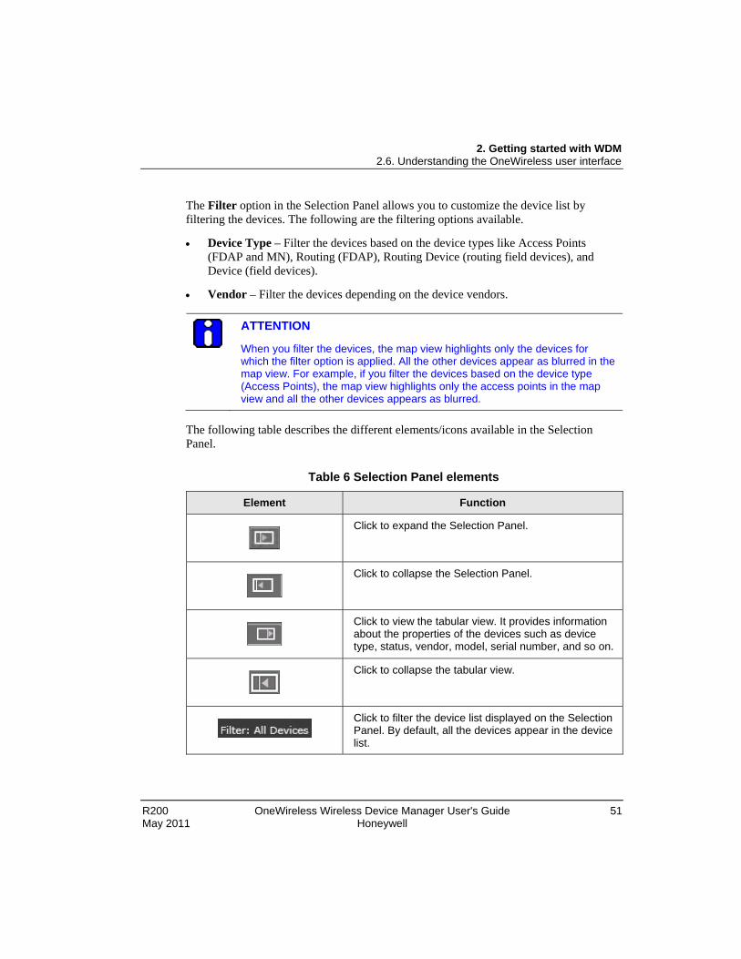
The Filter option in the Selection Panel allows you to customize the device list by filtering the devices. The following are the filtering options available.
• Device Type – Filter the devices based on the device types like Access Points (FDAP and MN), Routing (FDAP), Routing Device (routing field devices), and Device (field devices).
• Vendor – Filter the devices depending on the device vendors.
ATTENTION
When you filter the devices, the map view highlights only the devices for which the filter option is applied. All the other devices appear as blurred in the map view. For example, if you filter the devices based on the device type (Access Points), the map view highlights only the access points in the map view and all the other devices appears as blurred.
The following table describes the different elements/icons available in the Selection Panel.
Table 6 Selection Panel elements
Element Function
Click to expand the Selection Panel.
Click to collapse the Selection Panel.
Click to view the tabular view. It provides information about the properties of the devices such as device type, status, vendor, model, serial number, and so on.
Click to collapse the tabular view.
Click to filter the device list displayed on the Selection Panel. By default, all the devices appear in the device list.

2. Getting started with WDM 2.6. Understanding the OneWireless user interface
52 OneWireless Wireless Device Manager User's Guide R200 Honeywell May 2011
Element Function
Select the check box to organize the list of devices according to configured locations.
Click to add new locations.
Click to delete a location.
Figure 5 Tabular view of the Selection Panel

2. Getting started with WDM 2.6. Understanding the OneWireless user interface
R200 OneWireless Wireless Device Manager User's Guide 53 May 2011 Honeywell
The Show Radio Identification check box allows you to view the radio related details about the field devices. The following illustration depicts the tabular view of the Selection Panel with Show Radio Identification check box selected.
Figure 6 Tabular view with radio details of the devices
2. Getting started with WDM 2.6. Understanding the OneWireless user interface
54 OneWireless Wireless Device Manager User's Guide R200 Honeywell May 2011
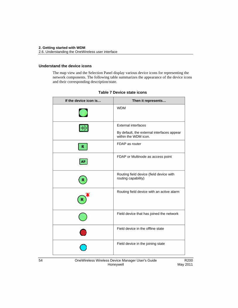
Understand the device icons The map view and the Selection Panel display various device icons for representing the network components. The following table summarizes the appearance of the device icons and their corresponding description/state.
Table 7 Device state icons
If the device icon is… Then it represents…
WDM
External interfaces
By default, the external interfaces appear within the WDM icon.
FDAP as router
FDAP or Multinode as access point
Routing field device (field device with routing capability)
Routing field device with an active alarm
Field device that has joined the network
Field device in the offline state
Field device in the joining state

2. Getting started with WDM 2.6. Understanding the OneWireless user interface
R200 OneWireless Wireless Device Manager User's Guide 55 May 2011 Honeywell
If the device icon is… Then it represents…
Channel icons
Channel in Auto mode
Channel in inactive/OOS mode
Channel becomes grey when the data is being fetched from the device. For a digital output channel, grey indicates the MAN mode, where you can manually set the output value.
Offline channel
Property Panel
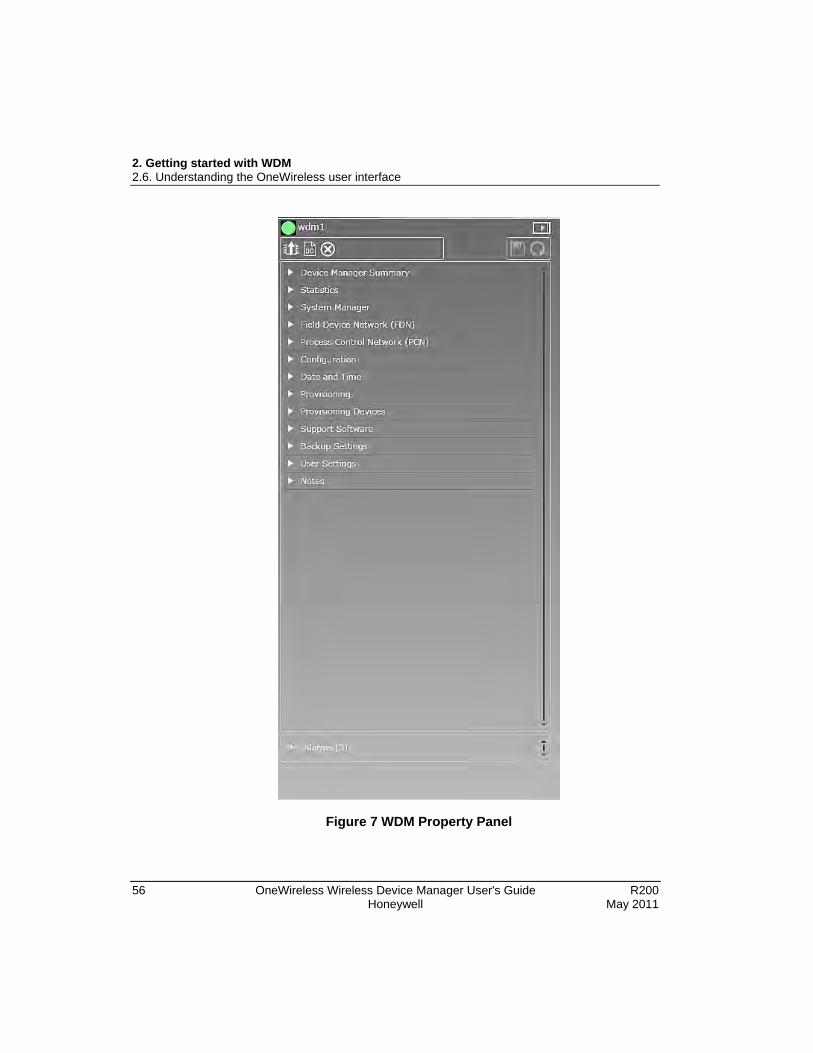
The Property Panel in the OneWireless user interface provides configuration properties of all the devices configured in the OneWireless Network. The Property Panel is docked to the right of the user interface window and is horizontally expandable and collapsible.
The Property Panel allows you to perform configuration tasks pertaining to the WDM, FDAPs, Multinodes, and field devices and their channels. It also allows monitoring the configuration attributes of the devices such as PV, communication links, signal quality, and so on.
Selecting the required device in the Selection Panel, automatically displays all the configuration parameters of the field devices that are accessible from the Property Panel. These configuration parameters are grouped into accordion panels that can be individually expanded or collapsed. The toolbar on the top of the Property Panel has options for some common device tasks such as upgrading the device firmware, loading the DD file, and so on.
2. Getting started with WDM 2.6. Understanding the OneWireless user interface
56 OneWireless Wireless Device Manager User's Guide R200 Honeywell May 2011
Figure 7 WDM Property Panel

2. Getting started with WDM 2.6. Understanding the OneWireless user interface
R200 OneWireless Wireless Device Manager User's Guide 57 May 2011 Honeywell
The following table describes the different elements/icons available in the Property Panel.
Table 8 Property Panel elements
Element Function
Click to expand the Property Panel.
Click to collapse the Property Panel.
Upgrade Firmware icon. Click to initiate firmware upgrade for the selected device.
Upload Device Definition File icon. Click to load the DD file.
Apply Changed Values icon. Click to save any configuration changes applied.
Reset icon. Click to reset any unsaved changes made to the devices through the Property Panel.
Alarms panel allows to view the alarm details (Priority, Start Time, and Description) for any device selected in the Selection Panel.

2. Getting started with WDM 2.6. Understanding the OneWireless user interface
58 OneWireless Wireless Device Manager User's Guide R200 Honeywell May 2011
Status bar The status bar that is located at the bottom of the user interface window displays messages that indicate the overall status of the network. These status messages are grouped into different panes in the status bar.
Table 9 Status bar panes
Pane Description
Number of online devices.
Displays all the active alarms. Click the Alarms box to open the Active Alarms table in the Alarm/Events tab.
Device replacement status is displayed when you have initiated a device replacement operation. Since the status bar displays the progress, you can close the Device Replacement dialog box to allow the replacement operation to run in the background. Click this box to open the Device Replacement dialog box.
Firmware upgrade status is displayed when you have initiated a firmware upgrade of any device. Since the status bar displays the progress, you can close the Firmware Upgrade dialog box to allow the operation to run in the background. Click this box to open the Firmware Upgrade dialog box.
Method status is displayed when you have calibrated any field device channel or replaced any device. Click the box to open the Method dialog box.

R200 OneWireless Wireless Device Manager User's Guide 59 May 2011 Honeywell
3. Configuration
3.1 Configuring a Provisioning Device handheld OneWireless Network uses Provisioning Device handhelds for authenticating the devices in the network. This section describes the tasks that must be performed to configure a Provisioning Device handheld.
Install synchronization software on the computer You must install synchronization software such as Microsoft ActiveSync or Windows Mobile Device Center on the computer. Microsoft ActiveSync is compatible only with Windows XP or earlier. If you are using a Windows 7 or Windows Vista system, download and install Windows Mobile Device Center.
Step Action
1 Using the following link, download the Microsoft ActiveSync 4.5 setup file (setup.msi) and save it to the computer.
http://www.microsoft.com/downloads/en/details.aspx?familyId=9E641C34-6F7F-404D-A04B-DC09F8141141&hash=ZXcqOkIz1vPfw73vwJQbLTHV8Xwio8UMvRuVGUr1w8v5qUjfU8QzIwuUfUo4uwyiyTbYehsyK3L1OUi7TYCd6g%3d%3d
For Windows Mobile Device Center, use the following link.
http://www.microsoft.com/downloads/en/details.aspx?FamilyId=46F72DF1-E46A-4A5F-A791-09F07AAA1914&displaylang=en
2 Browse to the hard disk drive location where the setup file is saved.
3 Run the setup file and follow the on-screen instructions to complete the installation.
Install Microsoft .NET Compact Framework 3.5 on the Provisioning Device handheld
Step Action
1 Using the following link, download the Microsoft .NET Compact Framework 3.5 setup file and save it to the computer.
http://www.microsoft.com/downloads/en/details.aspx?FamilyID=e3821449-3c6b-42f1-9fd9-0041345b3385&displaylang=en

3. Configuration 3.1. Configuring a Provisioning Device handheld
60 OneWireless Wireless Device Manager User's Guide R200 Honeywell May 2011
Step Action
2 Connect the Provisioning Device handheld’s docking station to a USB port on the computer.
3 Place the Provisioning Device handheld in the docking station.
Slide the bottom of the Provisioning Device handheld into the docking station and press firmly to place it on the docking station.
4 Switch on the Provisioning Device handheld.
5 The computer detects the Provisioning Device handheld and Synchronization Setup Wizard dialog box appears.
6 Click Cancel to continue.
It is not necessary to complete the synchronization setup before installing the Provisioning Device Application.
The Microsoft ActiveSync dialog box appears with the status as connected.
7 On the computer, browse to the location where Microsoft .NET Compact Framework 3.5 setup file is saved.
8 Run the setup file on the computer and follow the on-screen instructions to complete the installation.
The Provisioning Device handheld displays the progress of the installation.
ATTENTION
If Microsoft .NET Compact Framework 3.5 is already installed on the computer, in order to reinstall, you must remove it using Add/Remove Programs.

3. Configuration 3.1. Configuring a Provisioning Device handheld
R200 OneWireless Wireless Device Manager User's Guide 61 May 2011 Honeywell
Install Provisioning Device Application on the Provisioning Device handheld
Prerequisites
• Ensure that you have logged on to the OneWireless user interface.
• Ensure that the Provisioning Device handheld is connected to the computer and the connection status appears as green in ActiveSync on the computer.
Step Action
1 On the Selection Panel, select the WDM.
2 On the Property Panel, expand Support Software.
3 Under Provisioning Device Application Installer, click Save To.
The Save As dialog box appears.
4 Browse to a location on the hard drive to save the Provisioning Device Application.

3. Configuration 3.1. Configuring a Provisioning Device handheld
62 OneWireless Wireless Device Manager User's Guide R200 Honeywell May 2011
Step Action
5 Type the File Name and click Save.
The Provisioning Device Application is saved on the hard disk drive with a .cab extension. An example for the file name is ProvDevInstaller.cab.
Application Installer downloaded successfully message appears on the Support Software panel.
6 Browse to the location on the hard disk drive where you have saved the *.cab cabinet file and copy the file.
7 Open My Computer and double-click Mobile Device to open My Documents folder on the Provisioning Device handheld.
8 Paste the *.cab file on My Documents folder of the Provisioning Device handheld.
You can now remove the Provisioning Device handheld from the computer.
9 On the Provisioning Device handheld, tap Start > File Explorer and browse to My Documents.
10 Tap the *.cab cabinet file.
The message *.cab was successfully installed on your device appears.

3. Configuration 3.1. Configuring a Provisioning Device handheld
R200 OneWireless Wireless Device Manager User's Guide 63 May 2011 Honeywell
Step Action
11 To use the Provisioning Device Application, tap Start > Programs > Provisioning Device.
Before running the Provisioning Device Application, ensure you perform the following steps.
• Disable Receive all incoming beams option
a) Tap Start > Settings.
b) On the Connections tab, tap Beam.
c) Clear the Receive all incoming beams check box.
d) Tap Ok.
• Enable RNDIS Sync Mode
a) Tap Start > Settings.
b) On the Connections tab, tap ActiveSync Mode.
c) Under USB ActiveSync Interface, select RNDIS Sync Mode.
d) When the device prompts for soft reset, tap OK.

3. Configuration 3.1. Configuring a Provisioning Device handheld
64 OneWireless Wireless Device Manager User's Guide R200 Honeywell May 2011
Generate and transfer the provisioning keys to the Provisioning Device handheld
Prerequisites
• Ensure that Provisioning Device Application is installed on the Provisioning Device handheld.
• Ensure that the Provisioning Device Application is running on the Provisioning Device handheld.
Step Action
1 Connect the Provisioning Device handheld’s docking station to the USB port on the WDM.
2 In the OneWireless user interface, select the WDM on the Selection Panel.
3 On the Property Panel, expand Provisioning.

3. Configuration 3.1. Configuring a Provisioning Device handheld
R200 OneWireless Wireless Device Manager User's Guide 65 May 2011 Honeywell
Step Action
4 Click Transfer to PDA and type the following information under Settings.
• Name: Unique name used to identify the Provisioning Device handheld.
• Number of Keys: The number of provisioning keys to be transferred to the Provisioning Device handheld. These keys will be deployed to FDAPs, Multinodes, and field devices through the IR port. Maximum number of keys that can be transferred at a time is 100.
• Expiration (days): The expiration period for the provisioning keys in the Provisioning Device handheld. The maximum expiration period is 31 days. To calculate the expiration period correctly, ensure that the PDA time is manually synchronized with the system time.
ATTENTION
If the Provisioning Device handheld is already configured with the provisioning keys from another OneWireless Network or from the same network, the provisioning data from the earlier configuration is displayed on the Provisioning panel. To transfer the new keys, rewrite the values in the fields with the new values.
5 Click Transfer Settings.
This transfers the security keys from the WDM to the Provisioning Device handheld.
6 On the Provisioning Device handheld, tap Start > Programs > Provisioning Device.
The Provisioning Device screen appears.
7 Verify the Network ID, No. of keys, and Expiry that appears on the Provisioning Device handheld.

3. Configuration 3.1. Configuring a Provisioning Device handheld
66 OneWireless Wireless Device Manager User's Guide R200 Honeywell May 2011
Remove Provisioning Device handheld
Step Action
1 On the Selection Panel, select the WDM.
2 On the Property Panel, expand Provisioning Devices.
3 Select the check box for the Provisioning Device handheld to be removed.
4 Click Delete Selected Devices.
Deleting a Provisioning Device handheld, makes the security keys on the handheld invalid. To reuse the handheld, you must generate and transfer new provisioning keys to the handheld.

3. Configuration 3.2. Loading the Device Description file
R200 OneWireless Wireless Device Manager User's Guide 67 May 2011 Honeywell
3.2 Loading the Device Description file A Device Description (DD) file is usually a zip file that is available on the disk supplied by the vendor with the device or from the vendor’s Web site. It contains information about the device type, commands that are supported by the device, command 48 text descriptions, and other device-specific data. A DD file for a particular field device is used to describe the device and to interpret messages and device status.
ATTENTION
To ensure consistency in the channel names, load the DD files before the devices start joining the network.
Step Action
1 On the Selection Panel, select the WDM icon.
2 On the Property Panel, click the Upload Device Definition File icon.
The Load DD File dialog box appears.
3 Click Load DD File.
4 Browse to the directory location of the DD file.
5 Select the DD file and click Open.
The DD file is uploaded to the WDM and an upload success message appears.
6 Click Close to close the Load DD File dialog box.
7 Repeat steps 1 through 6 to load the DD files for all the device types.

3. Configuration 3.3. Provisioning the OneWireless Network components
68 OneWireless Wireless Device Manager User's Guide R200 Honeywell May 2011
3.3 Provisioning the OneWireless Network components Provision an FDAP/Multinode/field device
Provisioning an FDAP/Multinode/field device involves the process of transferring the security keys from the Provisioning Device handheld to the FDAP, Multinode, or a field device. This allows the devices to join the secure OneWireless Network and establish communication with the other devices and the WDM.
Prerequisites • Ensure that the FDAP/Multinode/field device is powered on.
• Provisioning Device Application must be installed on the Provisioning Device handheld.
• Provisioning Device handheld must be configured with valid keys from the WDM.
Step Action
1 On the Provisioning Device handheld, tap Start > Provisioning Device.
The Provisioning Device screen appears.
2 Tap Provisioning.
The Provisioning screen appears.
3 Hold the Provisioning Device handheld in line with the IR port of the FDAP/Multinode/field device and tap Provision a Device.
The Device provisioned successfully message appears.
4 Tap Ok.
The device joins the network and appears in the Selection Panel with a default name assigned by the WDM.

3. Configuration 3.3. Provisioning the OneWireless Network components
R200 OneWireless Wireless Device Manager User's Guide 69 May 2011 Honeywell
Step Action
ATTENTION
If the FDAP/Multinode/field device is already provisioned, a message displays on the Provisioning Device handheld screen, prompting to reset the device to default and try again. To restore the device settings:
1. Hold the Provisioning Device handheld in line with the IR port of the device to be provisioned.
2. Tap Reset to defaults on the Provisioning Device handheld.
5 Repeat the procedure to add the other FDAPs/Multinodes/field devices to the network.

3. Configuration 3.4. Configuring the WDM
70 OneWireless Wireless Device Manager User's Guide R200 Honeywell May 2011
3.4 Configuring the WDM Configure WDM properties
Using the Property Panel, you can view or modify the WDM properties like description, DHCP Server settings, network time settings, and so on. Although these configuration properties are configured during the initial configuration using the First Time Configuration Wizard, it is possible to modify them when required.
Configure default routing policy The default routing policy defines the routing behavior of a field device that is capable of operating as a router as well as an I/O device, after it joins the network.
Considerations
The default routing policy is not applicable for the following devices:
• Devices capable of operating as Access Points (Multinodes and FDAPs when connected to the backbone network).
• Devices capable of operating only as routers (FDAPs when not wired to the backbone network).
• Devices capable of operating only as I/O devices.
Step Action
1 On the Selection Panel, select the WDM.
2 On the Property Panel, expand System Manager.
3 Under ISA100 Network Topology, select Default Routing Policy as appropriate.

3. Configuration 3.4. Configuring the WDM
R200 OneWireless Wireless Device Manager User's Guide 71 May 2011 Honeywell
Step Action
The following are the routing policy options available.
Routing Enabled All field devices with routing capability function as a router as well as an I/O device.
Routing Enabled, Line Powered Only
Line-powered field devices with routing capability function as a router and an I/O device. In this case, battery powered field devices with routing capability will function only as I/O devices.
Routing Disabled All field devices with routing capability function only as I/O devices.
4 Type the Maximum Route Depth, as appropriate.
The Maximum Route Depth parameter specifies the maximum number of hops. Hops are defined as the number of routing devices through which the data must pass to reach its destination. By default, this parameter is set to four.
5 Type the Link Quality Threshold, as appropriate.
This corresponds to the RSQI value between the devices. The link between devices is established only if RSQI is equal to or greater than the Link Quality Threshold limit. By default, Link Quality Threshold is set to 127.
The Link Quality Threshold does not apply if the device has only one primary link.
6 Click the Apply Changed Values icon.
The configured routing policy is applicable only for devices that are joining the network for the first time.

3. Configuration 3.4. Configuring the WDM
72 OneWireless Wireless Device Manager User's Guide R200 Honeywell May 2011
Configure key rotation period
Step Action
1 On the Selection Panel, select the WDM.
2 On the Property Panel, expand System Manager.
3 Under ISA100 Network Security, select the Key Rotation Period as Infinite.
For best system performance, it is recommended to set the Key Rotation Period as Infinite.
4 Click the Apply Changed Values icon.

3. Configuration 3.5. Configuring field devices
R200 OneWireless Wireless Device Manager User's Guide 73 May 2011 Honeywell
3.5 Configuring field devices Configure field device properties
Step Action
1 On the Selection Panel, select the field device.
2 On the Property Panel, expand Field Device Summary.
3 Type the required Tag Name.
TIP
You can change the Tag Name by double-clicking the field device name in the Selection Panel.
4 Type the required Description.
5 Click the Apply Changed Values icon. Configure routing assignment
After joining the network for the first time, a field device capable of operating as a router and an I/O device initializes its routing assignment based on the current default routing policy. It is possible to override the default routing policy by configuring routing assignment for field devices. Configuring device routing assignment results in restarting the device with a new role.
Considerations
• Device routing assignment can be configured only for devices that are capable of operating as routers and I/O devices.
Step Action
1 On the Selection Panel, select the field device.
2 On the Property Panel, expand Device Management.
3 Select the Routing Assignment as appropriate.
The following are the Routing Assignment options available.
Routing Disabled Field device functions only as an I/O device even if the field device is capable of operating as a router and an I/O device.

3. Configuration 3.5. Configuring field devices
74 OneWireless Wireless Device Manager User's Guide R200 Honeywell May 2011
Step Action
Routing Enabled Field device with routing capability functions as a router as well as an I/O device.
Not Applicable • Does not apply to devices that are capable of operating as access points.
• Does not apply to devices that are only capable of operating as routers.
4 Click the Apply Changed Values icon. Configure publication rate and stale limit
The publication data for input and output field devices can be configured using the Input Publication and Output Publication panels in the Property Panel. Depending on the device type, a field device can have an Input Publication panel or an Output Publication panel. This is determined by the DD file for the field device.
The Input/Output Publication panel contains the following configuration options.
• Rate – The rate at which a field device publishes data.
• Stale Limit – Defines the maximum number of stale input values that can be received before the input status is set to Bad. It is recommended that for 1 second publication period, the stale limit should be set to 15 seconds. For all other publication periods (5 seconds, 10 seconds, 30 seconds, and 1 minute), the stale limit should be set to 5.
• Destination or Source – Destination of publication for output devices and source of publication for input devices, which is always the WDM.
• Channel – The list of channels for which the publication configuration applies.
ATTENTION
When a device joins the network, the WDM automatically configures its publication period as 5 seconds.
Step Action
1 On the Selection Panel, select the field device.
2 On the Property Panel, expand Input Publication or Output Publication.

3. Configuration 3.5. Configuring field devices
R200 OneWireless Wireless Device Manager User's Guide 75 May 2011 Honeywell
Step Action
3 In the Rate field, select the publication rate as appropriate.
4 In the Stale Limit field, select the stale limit as appropriate.
5 Click the Apply Changed Values icon.

3. Configuration 3.5. Configuring field devices
76 OneWireless Wireless Device Manager User's Guide R200 Honeywell May 2011
Calibrate field devices Calibration can be initiated either by manually setting the calibration parameters such as Cal Cmd, Cal Point High, Cal Point Low, and Cal Unit in the Calibration panel or by using the Invoke Method button. Invoke Method initiates the method manager, which guides you through the calibration process. All the field devices might not necessarily have the ability to calibrate. This is defined in the vendor supplied DD file.
To calibrate field device using Invoke Method
Step Action
1 On the Selection Panel, select the field device channel.
2 On the Property Panel, expand Mode and select the Target as OOS.
Ensure you change the target to OOS before starting calibration. You cannot perform calibration when the channel is online.
3 Click the Apply Changed Values icon.
4 In the Property Panel, expand Calibration.
5 Click Invoke Method to open the method dialog box.

3. Configuration 3.5. Configuring field devices
R200 OneWireless Wireless Device Manager User's Guide 77 May 2011 Honeywell
Step Action
6 Click Next and follow the instructions on-screen to complete calibration.
To cancel the calibration process at any stage of method execution, click Abort.
You can close the method dialog box while the method execution is in progress. To open the method dialog box again, click the method pane in the status bar.
Once complete, a message appears indicating that the calibration process completed successfully.
7 Select the Target as Auto to return the channel to the functioning mode.
8 Click the Apply Changed Values icon.
ATTENTION
• You can run only one method at a time for a field device using the current login session.
• If you close the Web browser while a method is running and logon as another user, you can start another method on the same device only after few minutes.
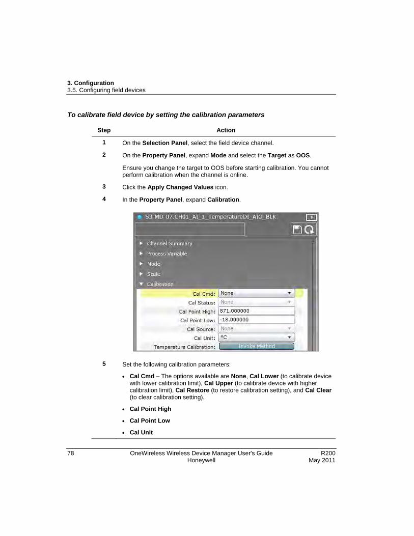
3. Configuration 3.5. Configuring field devices
78 OneWireless Wireless Device Manager User's Guide R200 Honeywell May 2011
To calibrate field device by setting the calibration parameters
Step Action
1 On the Selection Panel, select the field device channel.
2 On the Property Panel, expand Mode and select the Target as OOS.
Ensure you change the target to OOS before starting calibration. You cannot perform calibration when the channel is online.
3 Click the Apply Changed Values icon.
4 In the Property Panel, expand Calibration.
5 Set the following calibration parameters:
• Cal Cmd – The options available are None, Cal Lower (to calibrate device with lower calibration limit), Cal Upper (to calibrate device with higher calibration limit), Cal Restore (to restore calibration setting), and Cal Clear (to clear calibration setting).
• Cal Point High
• Cal Point Low
• Cal Unit

3. Configuration 3.5. Configuring field devices
R200 OneWireless Wireless Device Manager User's Guide 79 May 2011 Honeywell
Step Action
6 Click the Apply Changed Values icon.
7 Select the Target as Auto to return the channel to functioning mode.
8 Click the Apply Changed Values icon.

3. Configuration 3.6. Configuring field device channels
80 OneWireless Wireless Device Manager User's Guide R200 Honeywell May 2011
3.6 Configuring field device channels Configure Mode and Scale
You can configure or modify channel attributes like Mode and Scale from the Property Panel.
Step Action
Configure Scale
1 On the Selection Panel, select the field device channel.
2 On the Property Panel, expand Process Variable to configure the following attributes.
• EU at 100%: Specifies the high range PV value in Engineering Units.
• EU at 0%: Specifies the low range PV value in Engineering Units.
• Units Index: Specifies the unit of the measurement value. The value varies according to the sensor type selected for a channel. For example, in a temperature device, when the sensor type changes to a thermocouple (TC-J) or mV-50 range, the transducer block sets the Units Index to °C or mV.
3 Click the Apply Changed Values icon.
Note: After applying the changes, the newly configured values appear under the Scale panel.
Configure Mode
4 On the Property Panel, expand Mode.
5 In the Target list, select the mode as required.
The mode types available are Normal, OOS, and Auto. If the device type is Digital Output (DO), an additional mode Man is also available in the Target list.
6 Click the Apply Changed Values icon.
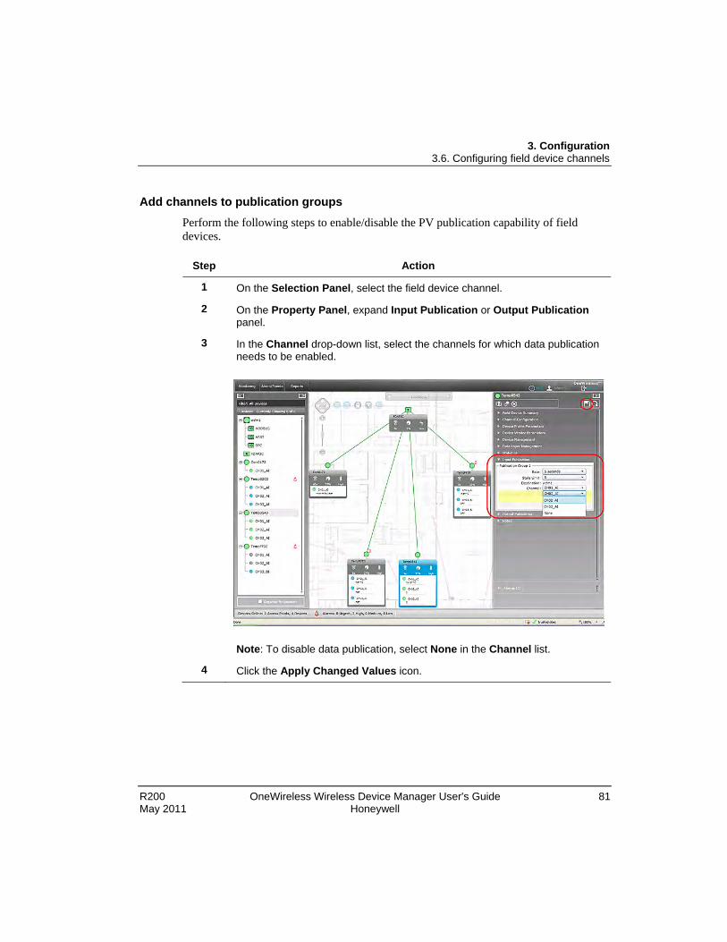
3. Configuration 3.6. Configuring field device channels
R200 OneWireless Wireless Device Manager User's Guide 81 May 2011 Honeywell
Add channels to publication groups Perform the following steps to enable/disable the PV publication capability of field devices.
Step Action
1 On the Selection Panel, select the field device channel.
2 On the Property Panel, expand Input Publication or Output Publication panel.
3 In the Channel drop-down list, select the channels for which data publication needs to be enabled.
Note: To disable data publication, select None in the Channel list.
4 Click the Apply Changed Values icon.

3. Configuration 3.6. Configuring field device channels
82 OneWireless Wireless Device Manager User's Guide R200 Honeywell May 2011
Configure channel instantiation OneWireless Network supports block instantiation for field device channels. You can add, remove, and reconfigure channels on supported field devices. An individual channel can be configured for one of the several roles, such as an analog temperature input, an analog current input, or a discrete input.
You can instantiate channels, only for supported field devices from Honeywell.
• XYR 6000 Multi AI DI
• XYR 6000 Multi AI DI DO
• XYR 6000 Temp DI
You can add, remove, and reconfigure channels on a supported field device using the user interface.
Step Action
Set channel to OOS mode
1 On the Selection Panel, select the field device channel.
2 On the Property Panel, expand Mode.
3 In the Target list, click OOS and then click the Apply Changed Values icon.
The channel icon appears as blue indicating the OOS mode.
Remove channel from publication group
4 On the Selection Panel, select the field device.
5 On the Property Panel, expand Input Publication.
6 For the channel to be removed from the publication group, click None in the Channel drop-down list.
7 Click the Apply Changed Values icon.
Wait for a few seconds to apply the changes.
Note: Before proceeding, ensure you collapse the Input Publication panel.
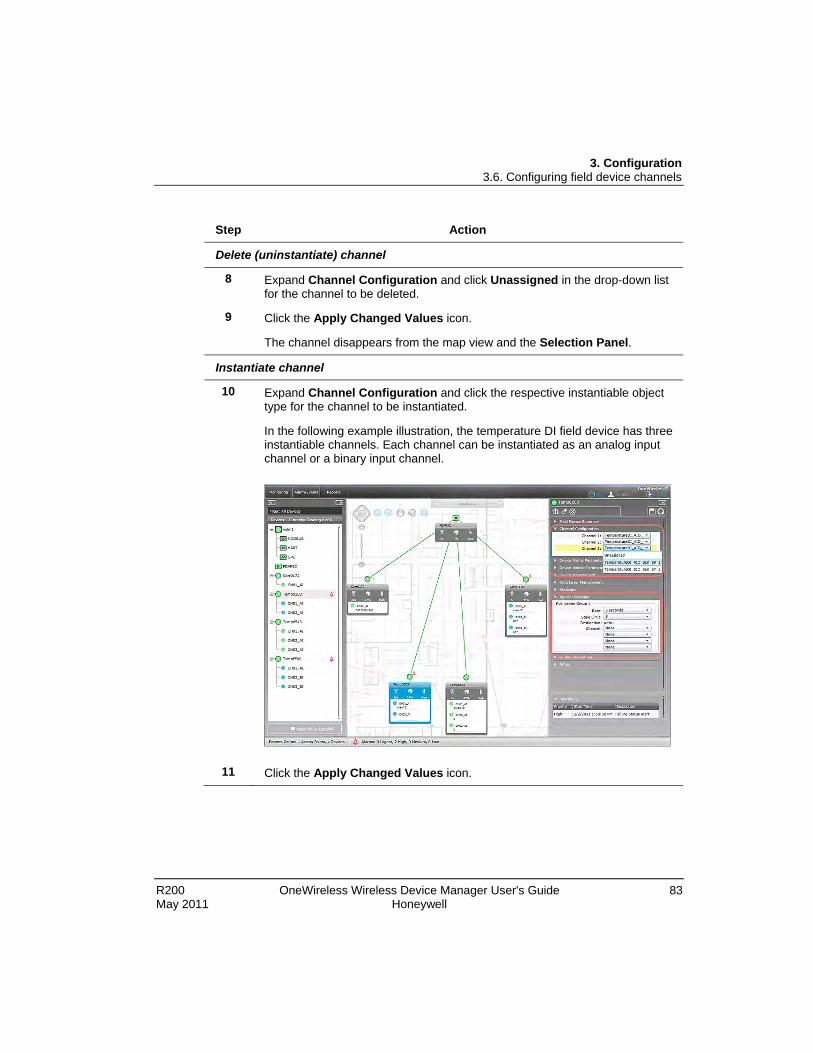
3. Configuration 3.6. Configuring field device channels
R200 OneWireless Wireless Device Manager User's Guide 83 May 2011 Honeywell
Step Action
Delete (uninstantiate) channel
8 Expand Channel Configuration and click Unassigned in the drop-down list for the channel to be deleted.
9 Click the Apply Changed Values icon.
The channel disappears from the map view and the Selection Panel.
Instantiate channel
10 Expand Channel Configuration and click the respective instantiable object type for the channel to be instantiated.
In the following example illustration, the temperature DI field device has three instantiable channels. Each channel can be instantiated as an analog input channel or a binary input channel.
11 Click the Apply Changed Values icon.

3. Configuration 3.6. Configuring field device channels
84 OneWireless Wireless Device Manager User's Guide R200 Honeywell May 2011
Step Action
Add channel to publication group
12 On the Property Panel, expand Input Publication panel.
13 In the Channel drop-down list, click the channel for which data publication needs to be enabled.
14 Click the Apply Changed Values icon.
Set channel to Auto mode
15 On the Selection Panel, select the field device channel.
16 On the Property Panel, expand Mode.
17 In the Target list, click Auto and then click the Apply Changed Values icon.
The channel icon appears as green indicating Auto mode.
3. Configuration 3.6. Configuring field device channels
R200 OneWireless Wireless Device Manager User's Guide 85 May 2011 Honeywell
Remove channels from publication groups
Step Action
1 On the Selection Panel, select the field device channel.
2 On the Property Panel, expand Input Publication.
3 For the channel to be deleted from the publication group, click None in the Channel drop-down list.
4 Click the Apply Changed Values icon. Delete (uninstantiate) channels
Prerequisites • Ensure that the channel is set to OOS mode.
• Ensure that the channel is not configured for publication in any of the Input/Output Publication groups. If configured, remove the channel from the Publication group.
Step Action
1 On the Selection Panel, select the device with instantiated channel.
2 On the Property Panel, expand Channel Configuration.
The Channel Configuration panel displays a list of instantiated channels.
3 Select the channel to delete and select Unassigned in the corresponding drop-down list.
4 Click the Apply Changed Values icon.

3. Configuration 3.7. Adding notes for devices
86 OneWireless Wireless Device Manager User's Guide R200 Honeywell May 2011
3.7 Adding notes for devices You can add device notes for WDM, FDAPs, Multinodes, or field devices. These notes can be used as a logbook for the device. Perform the following steps to add notes for any configured device. Note that the notes added for devices are saved on the WDM and not on the device.
Step Action
1 On the Selection Panel, select the required device.
2 On the Property Panel, expand Notes.
3 Click the Add note icon.
A text box appears.
4 Type the note and click Apply Changes Values icon.
ATTENTION
• All users can view all the notes added by other users.
• To delete any note added, click delete icon adjacent to the note.
− Users with User role can delete only notes added by them.
− Users with Administrator role can delete other user’s notes.
• Notes are not restored during a replace operation.
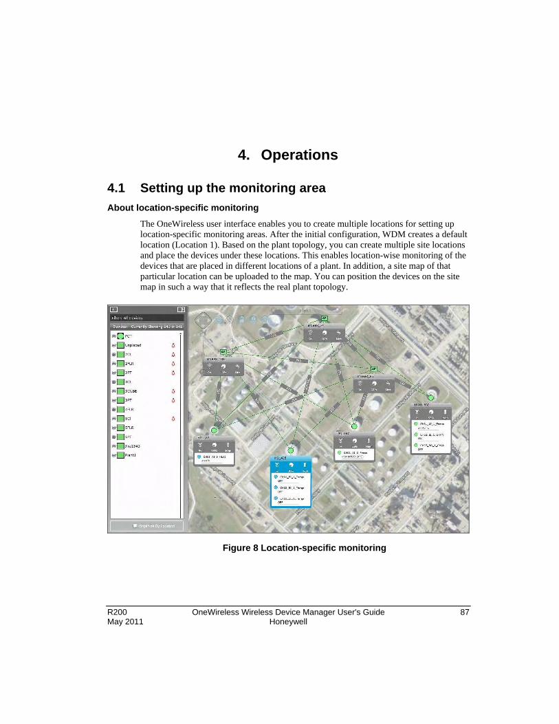
R200 OneWireless Wireless Device Manager User's Guide 87 May 2011 Honeywell
4. Operations
4.1 Setting up the monitoring area About location-specific monitoring
The OneWireless user interface enables you to create multiple locations for setting up location-specific monitoring areas. After the initial configuration, WDM creates a default location (Location 1). Based on the plant topology, you can create multiple site locations and place the devices under these locations. This enables location-wise monitoring of the devices that are placed in different locations of a plant. In addition, a site map of that particular location can be uploaded to the map. You can position the devices on the site map in such a way that it reflects the real plant topology.
Figure 8 Location-specific monitoring

4. Operations 4.1. Setting up the monitoring area
88 OneWireless Wireless Device Manager User's Guide R200 Honeywell May 2011
Configure site locations
Step Action
1 On the Selection Panel, click Organize by Location.
2 Click Add Location icon.
A new location is added with the default name as Location <n>, where n is an integer, which increases with every newly added location.
To delete any location, click the location name and click Delete Location button at the bottom of the Selection Panel. After deleting a location, all the devices configured in that particular location are listed under the Unplaced location. Note that you cannot delete the default location (Location1).
3 On the Selection Panel, click the newly added location.
4 On the Property Panel, expand Location Summary.
The Location Summary displays the location details such as default location name, description, and the current map image.
5 To change the default location name, type the new name in the Location Name field.
6 In the Description field, type the description of the location.
7 Click Load New Map.
The Open dialog box appears.

4. Operations 4.1. Setting up the monitoring area
R200 OneWireless Wireless Device Manager User's Guide 89 May 2011 Honeywell
Step Action
8 Browse to the location where the site map is saved and select the site map.
ATTENTION
The site map must be a .jpg file of any size. The screen resolution can be a minimum of 256x256 and a maximum of 4416x3312.
9 Click Open to upload the site map.
ATTENTION
• By default, the map display is hidden. To display the map, use the Show/Hide Map control on the top-left of the map view.
• To increase or decrease map visibility use the fade in /fade out control on the map view.
For more information about map controls, refer to the section, About map view.
Use the Remove Map button on the Location Summary panel, to remove any previously loaded site map for the location.
Position the devices on the map
After uploading the site map for a particular location, you can position the devices on the map to reflect the physical design and structure of your plant. The devices do not appear on the map view, by default.
Step Action
1 On the Selection Panel, select the device to be positioned on the map.
2 Drag the device and drop it on the required location on the map.
3 Repeat steps 1 and 2 to place the other devices.
4 Click the Lock/Unlock control on the map view to lock the map.
You must lock the map to prevent device locations from being accidentally modified.

4. Operations 4.2. Configuring alerts for field devices
90 OneWireless Wireless Device Manager User's Guide R200 Honeywell May 2011
4.2 Configuring alerts for field devices You can configure to enable or disable the following alerts for field devices.
• Maintenance Required alerts: Generated to indicate a low battery or low external power condition.
• Out of Specification Status alerts: Generated for calibration errors, thermocouple condition warning, or indeterminate discrete input state.
• Failure Status alerts: Generated for fault conditions such as input failure, output failure, or electronic failure.
Step Action
1 On the Selection Panel, select the field device.
2 On the Property Panel, expand Device Vendor Parameters.
3 For the type of alert that is required to be configured, perform one of the following.
• To enable alert generation, clear the Alert Disable check box.
• To disable alert generation, select the Alert Disable check box.
4 Set the Alert Priority.
The Alert Priority can contain the following values.
• 0-2: Journal (only events are reported)
• 3-5: Low
• 6-8: Medium
• 9-11: High
• 12-15: Urgent
5 Click the Apply Changed Values icon.

4. Operations 4.3. Verifying connectivity using maps
R200 OneWireless Wireless Device Manager User's Guide 91 May 2011 Honeywell
4.3 Verifying connectivity using maps Perform the following steps, to verify mesh connectivity and device connectivity.
Step Action
1 Click the Monitoring tab to view the map view.
2 Visually inspect network topology map and connectivity.
3 Navigate to the device in the topology map and check the link signal quality and connectivity.
4 Verify device communication statistics information like RSQI and RSSI.
RSQI range 192 to 255: Excellent
128 to 192: Good
64 to 128: Fair
0 to 64: Poor
RSSI range -25 to -70: Good
-75 to -85: Medium
-85 to -100: Weak

4. Operations 4.4. Monitoring the network and devices
92 OneWireless Wireless Device Manager User's Guide R200 Honeywell May 2011
4.4 Monitoring the network and devices You can monitor the performance of the network and the devices that have joined the network. All the devices that have joined the network are accessible from the Selection Panel. The tabular view allows you to view the details about devices in the network.
Figure 9 Monitoring the network using the tabular view

4. Operations 4.4. Monitoring the network and devices
R200 OneWireless Wireless Device Manager User's Guide 93 May 2011 Honeywell
The following tables explain the device and channel attributes that are available in the tabular view.
Table 10 Device attributes in the tabular view
Device attribute Description
Tag Name Name of the device.
Type Device type, which can contain the following values.
• Device Manager for WDM.
• Access Point for FDAP and Multinode.
• Device, Routing for field devices.
• Device for non-routing field devices.
Status Device status.
The status can be Offline, Joining, or Joined.
Vendor Device vendor name
Model Device model.
For example, XYR 6000 HLAI is the device model for Honeywell HLAI device.
Revision Device sensor firmware revision number.
To view the radio firmware revision, select the Show Radio Identification check box.
Serial Serial number of the device.
IP6 Address IPv6 address of the device.
Power Source Power source of the device, which can contain the following values.
• Line for line powered FDAPs or WDM.
• High, Low or Medium for battery powered field devices.

4. Operations 4.4. Monitoring the network and devices
94 OneWireless Wireless Device Manager User's Guide R200 Honeywell May 2011
Table 11 Channel attributes in the tabular view
Channel attribute Description
Tag Name Channel name
Channel Channel number
Mode Device channel mode, which contains the values AUTO, OOS, or MAN.
Value Process Value
Status PV status
You can view the PV trend in the Values and Trends panel of the channel’s Property Panel.

4. Operations 4.5. Monitoring alarms and events
R200 OneWireless Wireless Device Manager User's Guide 95 May 2011 Honeywell
4.5 Monitoring alarms and events The Alarm/Events tab in the user interface allows you to monitor the alarms and events generated by the devices. The Active Alarms tab displays the category, description, priority, location, source, reported value, and time. The Alarms/Event History tab provides a tabular view of the events, displays event class, event category, priority, event start time, event source, location, and description. You can also export the alarm log and event log for a particular period.
Step Action
1 Click the Alarm/Events tab.
The Alarm/Events page displays.
2 Click the Active Alarms tab.
The Active Alarms page displays details about the active alarms.
3 To view the alarm details, click on any alarm and expand Alarm Detail at the bottom of the pane.
The Alarm Detail pane displays details such as Alarm Category, Location, Alarm Duration, Reported Value, and Recent Alarm History, for any selected device.
4 Click the Alarms/Events History tab.
The Alarms/Events History page displays details about all the alarms (active and inactive) and events.

4. Operations 4.5. Monitoring alarms and events
96 OneWireless Wireless Device Manager User's Guide R200 Honeywell May 2011
Step Action
When an alarm is reported, the Event Class column displays a red alarm symbol. When the alarm returns to normal, the alarm symbol changes to black.
The following are the events that are reported in the Alarms/Events History.
• Communications Diagnostic: Reported for events such as device offline, device joining, device online, alarm recovery start, alarm recovery end, and so on.
• Device Diagnostic: Reported for events such as device restart, alarm recovery start, and alarm recovery end.
• Security: Reported for security-based events.

4. Operations 4.5. Monitoring alarms and events
R200 OneWireless Wireless Device Manager User's Guide 97 May 2011 Honeywell
Step Action
5 To export an alarm or event log
1. Click Export Alarm Log or Export Event Log.
2. On the Export Logs dialog box, click the export option using which the log needs to be exported. The following are the available export options.
− Entire log
− From last hours…: Specify the number of hours for which the log needs to be exported.
− From time period…: Specify the From Date and To Date to export the log for that particular period.
3. Click Export.
The alarm or event log is exported in the .csv format.

4. Operations 4.6. Viewing license agreement files
98 OneWireless Wireless Device Manager User's Guide R200 Honeywell May 2011
4.6 Viewing license agreement files Honeywell End User License Agreement (EULA) and third party licenses are available at the following locations.
• Honeywell EULA: https://<WDM IP Address>/licenses/Third_Party_Licenses.txt
• Third-party licenses: https://<WDM IP Address>/licenses/Honeywell_End_User_License_Agreement.txt

R200 OneWireless Wireless Device Manager User's Guide 99 May 2011 Honeywell
5. Activate process control interfaces
5.1 Establishing connection between WDM and external interfaces
Perform the following steps to connect OPC, Modbus, and HART interfaces to the PCN port of the WDM.
Step Action
1 Connect the external interface client to the PCN port of WDM.
You can use a switch if you have multiple interfaces to connect to the WDM.
For serial interface connection, connect a serial cable from the interface client to the serial port on the WDM.
5.2 Activating HART in OneWireless Network
The ISA100.11a field devices maintain a database of process configuration, identification, and diagnostic information in memory. WDM allows accessing this information from asset management systems, such as Field Device Manager (FDM), through a HART interface. This enables monitoring the ISA100.11a field devices like any other HART device. OneWireless network uses serial communication interface to support data transmission between the asset management systems and the WDM.
It also uses Ethernet/UDP interface for data transmission. Ethernet/UDP communication allows users to tunnel serial communication to Ethernet. Serial communication can be tunneled to Ethernet by using a Lantronix device or serial-to-Ethernet/UDP driver on the asset management system.
Configure HART serial interface
Prerequisites
Ensure the following:
• The asset management system is connected to the process control network.
• The asset management system is connected to the WDM using a serial cable.
To access the field device data from the asset management system, you need to configure the HART interface from the OneWireless user interface.

5. Activate process control interfaces 5.2. Activating HART in OneWireless Network
100 OneWireless Wireless Device Manager User's Guide R200 Honeywell May 2011
Step Action
1 On the Selection Panel, expand the WDM icon and select HART.
2 On the Property Panel, expand Configuration and select Interface as Serial Interface.
3 Under Serial Interface Options, select the following fields.
• Serial Port: Select the serial port on which the serial cable is connected.
• Baud Rate: Select 9600 as the baud rate for HART serial interface.
• Parity: Select the parity as Odd.
4 By default, the Polling Address contains the value 0. This represents the polling address of the emulated HART MUX on the HART interface.
5 Click the Apply Changed Values icon.

5. Activate process control interfaces 5.2. Activating HART in OneWireless Network
R200 OneWireless Wireless Device Manager User's Guide 101 May 2011 Honeywell
Step Action
6 Expand Vendor and Model Table.
The Vendor and Model Table is used to configure mapping between ISA100.11a vendor and model strings with HART manufacturer ID and device type bytes. This mapping is required for native ISA100.11a devices functioning as HART devices. The HART protocol uses a manufacturer ID byte and device type byte when identifying a device. This table is used to configure a lookup table that maps the ISA100.11a vendor and model strings with HART manufacturer ID and the device type bytes. The Vendor and Model Table contains the following columns.
• Vendor String: The ISA100.11a vendor string of the native ISA100.11a device.
• Model String: The ISA100.11a model string of the native ISA100.11a device.
• Manufacturer ID: The HART manufacturer ID byte used to represent the native ISA100.11a device.
• Device Type: The HART device type byte used to represent the native ISA100.11a device.
Note: The Vendor and Model Table is pre-configured for Honeywell field devices. No configuration is required if your device vendor and model is pre-configured. Native HART devices connected using the OneWireless Adapter do not use the Vendor and Model Table.
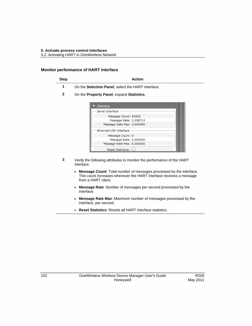
5. Activate process control interfaces 5.2. Activating HART in OneWireless Network
102 OneWireless Wireless Device Manager User's Guide R200 Honeywell May 2011
Monitor performance of HART interface
Step Action
1 On the Selection Panel, select the HART interface.
2 On the Property Panel, expand Statistics.
3 Verify the following attributes to monitor the performance of the HART interface.
• Message Count: Total number of messages processed by the interface. This count increases whenever the HART interface receives a message from a HART client.
• Message Rate: Number of messages per second processed by the interface.
• Message Rate Max: Maximum number of messages processed by the interface, per second.
• Reset Statistics: Resets all HART interface statistics.

5. Activate process control interfaces 5.2. Activating HART in OneWireless Network
R200 OneWireless Wireless Device Manager User's Guide 103 May 2011 Honeywell
Monitor field devices from an asset management system The following procedure describes the steps to access the field devices using FDM. The steps in this procedure provide only an overview of tasks that you need to perform. For detailed information on tasks that you need to perform using FDM, refer to the FDM user documentation.
Step Action
1 Log on to the FDM server and configure the following using FDM Server Management Tool.
1. Configure RS-485 HART Multiplexer for enabling communication between HART client and the ISA100.11a field devices.
2. Configure the Network Interface Name and Remote Communication Interface Server Name.
3. Configure the following network specific parameters.
− COM Port: COM port on the WDM to which the serial cable is connected.
− BAUD Rate: 9600
− Start Poll Address and End Poll Address: 0 to 127
2 Start the FDM server using the FDM Server Management Tool.
3 Log on to the FDM Client and scan for the field devices.

5. Activate process control interfaces 5.2. Activating HART in OneWireless Network
104 OneWireless Wireless Device Manager User's Guide R200 Honeywell May 2011
Step Action
Once the FDM Client scans the devices, the WDM and the devices appear on the FDM Client as displayed in the following illustration.
4 For accessing the field device parameters, add HART DD files for the field devices.

5. Activate process control interfaces 5.2. Activating HART in OneWireless Network
R200 OneWireless Wireless Device Manager User's Guide 105 May 2011 Honeywell
Step Action
After accessing the parameters, the HART Client displays the device details as follows.

5. Activate process control interfaces 5.3. Activating Modbus in Onewireless Network
106 OneWireless Wireless Device Manager User's Guide R200 Honeywell May 2011
5.3 Activating Modbus in Onewireless Network Using any Modbus application, you can read any standard measurement or status of field devices. The WDM functions as the Modbus server and allow clients to access point data. The Modbus interface within the WDM supports Modbus TCP and Modbus RTU. Modbus interface supports coils, discrete inputs, holding registers, or input registers. It can associate only standard measurement and status of field device within the network with a coil, discrete input, holding register, or input register. The coil and discrete input are used for digital input and output modules. The holding register and input register are used for analog input and output modules.
Figure 10 Modbus TCP communication

5. Activate process control interfaces 5.3. Activating Modbus in Onewireless Network
R200 OneWireless Wireless Device Manager User's Guide 107 May 2011 Honeywell
Figure 11 Modbus RTU communication Prerequisite
• Ensure that you have installed the Modbus client.

5. Activate process control interfaces 5.3. Activating Modbus in Onewireless Network
108 OneWireless Wireless Device Manager User's Guide R200 Honeywell May 2011
Step Action
1 On the Selection Panel, expand the WDM icon and select Modbus.
2 On the Property Panel, expand Configuration.

5. Activate process control interfaces 5.3. Activating Modbus in Onewireless Network
R200 OneWireless Wireless Device Manager User's Guide 109 May 2011 Honeywell
Step Action
3 Under Interface, select the required Interface option.
The following are the interface options available.
• Modbus TCP Interface: If Modbus TCP is enabled, then under Modbus TCP Options, type the TCP Port used for the Modbus TCP interface.
• Modbus RTU Interface: If Modbus RTU is enabled, then under Modbus RTU Options, select the appropriate values for the following fields.
− Serial Port: Select the serial port used for the Modbus RTU interface. Options include COM1, COM2, or COM3.
− Baud Rate: Select the baud rate used for the Modbus RTU serial port.
− Parity: Select the parity used for the Modbus RTU serial port.
4 Under Byte Order, select the Byte Order for 32-bit holding register and input register values.
You should select a byte order that matches the expected byte order of the Modbus client. Options include Big Endian, Big Endian Byte Swapped, Little Endian, and Little Endian Byte Swapped.
5 Under Unconfigured Register Response, select Read Response and Write Response.
If you select the Read Response as “Zero,” for unmapped registers the Modbus client displays zero. If you select Read Response as “Illegal Exception,” then the server sends an exception response and returns no values.
6 Under Read Register Error Response, select Float Error Response and type Float and Integer Error Value.
If you select the Float Error Response as “NAN” and if the floating PV is not available, then the client displays “NAN.” If you have selected the Float Error Response as “Float Error value” and input any value in the Float Error Value register, it displays the float error value in the client when the floating PV is not available in the client.
If you select the Integer Error Response as “Zero” and if the integer PV is not available, then the client displays “Zero.” If you have selected the Integer Error Response as “Integer Error value” and input any value in Integer Error value register, it displays Integer Error value in the client when the Integer PV is not available in the client.
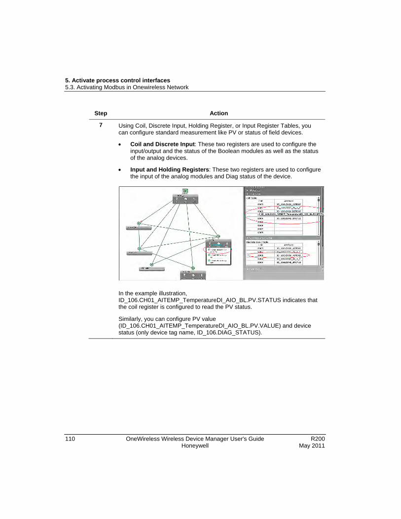
5. Activate process control interfaces 5.3. Activating Modbus in Onewireless Network
110 OneWireless Wireless Device Manager User's Guide R200 Honeywell May 2011
Step Action
7 Using Coil, Discrete Input, Holding Register, or Input Register Tables, you can configure standard measurement like PV or status of field devices.
• Coil and Discrete Input: These two registers are used to configure the input/output and the status of the Boolean modules as well as the status of the analog devices.
• Input and Holding Registers: These two registers are used to configure the input of the analog modules and Diag status of the device.
In the example illustration, ID_106.CH01_AITEMP_TemperatureDI_AIO_BL.PV.STATUS indicates that the coil register is configured to read the PV status.
Similarly, you can configure PV value (ID_106.CH01_AITEMP_TemperatureDI_AIO_BL.PV.VALUE) and device status (only device tag name, ID_106.DIAG_STATUS).

5. Activate process control interfaces 5.3. Activating Modbus in Onewireless Network
R200 OneWireless Wireless Device Manager User's Guide 111 May 2011 Honeywell
Step Action
8 Click Statistics to monitor the performance of the Modbus interface using the following parameters.
Under Modbus RTU Interface and Modbus TCP Interface,
• Message Count: Total number of messages processed by the interface. The count should increase with every message sent by a Modbus client. If the count is not incrementing, it indicates that the Modbus interface on the WDM is not receiving messages from the client.
• Message Rate: Number of messages processed by the interface per second.
• Message Rate Max: Maximum number of messages processed by the interface per second.
• CRC Error Count: Total number of CRC errors recorded by the Modbus RTU interface. The count should increase if any CRC errors are detected when receiving a message sent by the Modbus RTU client.
• CRC Error Rate: Number of CRC errors recorded by the Modbus RTU interface per second.
• CRC Error Rate Max: Maximum number of CRC errors recorded by the Modbus RTU interface per second.
Under Coils, Discrete Inputs, Holding Registers, Input Registers, and Exceptions,
• Read: Total number of read messages processed by the interface.
• Write: Total number of write messages processed by the interface.
• Exception: Total number of exceptions, such as invalid request messages.
• Timeout: Total number of timeouts.
• Reset Statistics: Resets all Modbus interface statistics.

5. Activate process control interfaces 5.4. Activating OPC in OneWireless Network
112 OneWireless Wireless Device Manager User's Guide R200 Honeywell May 2011
5.4 Activating OPC in OneWireless Network WDM hosts an OPC Unified Architecture (UA) server, which provides open system communication to ISA100.11a data (current, historical and alarm/event data). OPC UA provides a Service Oriented Architecture (SOA) for industrial applications. For the OPC based applications that only support DCOM/COM based OPC, WDM offers an OPCUA Proxy. OPCUA Proxy when installed on the client machine enables communication between a DCOM/COM-based OPC client and the WDM.
Several clients are used to connect the WDM to an OPC server. The Unified Automation UAExpert and OPC Validator are the sample clients that are used by Honeywell for configuring OPC. The procedures to configure an OPC client (for OPC UA and Classic OPC) in this document are based on Unified Automation UAExpert and OPC Validator.
Configure OPC UA client system
Figure 12 OPC Interface

5. Activate process control interfaces 5.4. Activating OPC in OneWireless Network
R200 OneWireless Wireless Device Manager User's Guide 113 May 2011 Honeywell
Prerequisite
• Install Microsoft .NET Framework 3.5 SP1 and OPC UAExpert Client in the client system.
Step Action
1 On the desktop of the client system, double-click Unified Automation UAExpert icon.
The Unified Automation UAExpert window appears.
2 On the Server menu, click Add to add the OPC server to be connected to the client.
The Add Server dialog box appears.

5. Activate process control interfaces 5.4. Activating OPC in OneWireless Network
114 OneWireless Wireless Device Manager User's Guide R200 Honeywell May 2011
Step Action
3 Type the Configuration Name.
4 Click the Discovery tab to view all the available servers. There is only one OPC UA server available for a WDM, and its port number is 4840.
5 Click the Advanced tab and then type the IP address of the WDM and the port number in the Endpoint url field.
The OPC server IP address with port number is opc.tcp://192.168.1.1:4840.
6 Under Security Settings, ensure that Security Policy and Message Security Mode are selected as None.
There is only one OPC UA server available for a WDM, but with multiple security modes. Multiple levels of security are allowed in configuring the OPC UA connection to the server.
7 Under Authentication Settings, click Anonymous.
8 Select Connect Automatically check box.
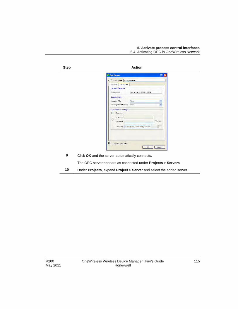
5. Activate process control interfaces 5.4. Activating OPC in OneWireless Network
R200 OneWireless Wireless Device Manager User's Guide 115 May 2011 Honeywell
Step Action
9 Click OK and the server automatically connects.
The OPC server appears as connected under Projects > Servers.
10 Under Projects, expand Project > Server and select the added server.

5. Activate process control interfaces 5.4. Activating OPC in OneWireless Network
116 OneWireless Wireless Device Manager User's Guide R200 Honeywell May 2011
Step Action
11 To monitor the PV value of any field device,
a) In the Address Space pane, under Root expand Objects > Transmitter > Transmitter Channel.
b) Click PV.
The selected PV attributes appear in the Attribute Window pane.

5. Activate process control interfaces 5.4. Activating OPC in OneWireless Network
R200 OneWireless Wireless Device Manager User's Guide 117 May 2011 Honeywell
Step Action
12 Drag and drop any parameter from the Address Space pane to the Default DA View to increase the load of the network.
The OPC Statistics pane in the OneWireless user interface displays the following information about the loaded parameters.
• Subscription Count
• Subscription Rate
• Subscription Rate Max

5. Activate process control interfaces 5.4. Activating OPC in OneWireless Network
118 OneWireless Wireless Device Manager User's Guide R200 Honeywell May 2011
Install OPC proxies You can setup OPC proxies on a client machine so that an OPC Classic client (a non-UA client) can connect to the OPC UA server on the WDM. The proxy files are available on the WDM.
Figure 13 OPC client with Classic OPC
Perform the following steps to load OPC proxies.
Step Action
1 In the Web browser window, type the following address.
WDM IP address/opc_proxies/setup.exe
For example, if the IP address of the WDM is 192.168.1.1, then type, http://192.168.1.1/opc_proxies/setup.exe.
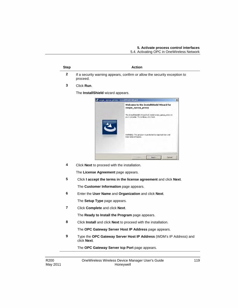
5. Activate process control interfaces 5.4. Activating OPC in OneWireless Network
R200 OneWireless Wireless Device Manager User's Guide 119 May 2011 Honeywell
Step Action
2 If a security warning appears, confirm or allow the security exception to proceed.
3 Click Run.
The InstallShield wizard appears.
4 Click Next to proceed with the installation.
The License Agreement page appears.
5 Click I accept the terms in the license agreement and click Next.
The Customer Information page appears.
6 Enter the User Name and Organization and click Next.
The Setup Type page appears.
7 Click Complete and click Next.
The Ready to Install the Program page appears.
8 Click Install and click Next to proceed with the installation.
The OPC Gateway Server Host IP Address page appears.
9 Type the OPC Gateway Server Host IP Address (WDM’s IP Address) and click Next.
The OPC Gateway Server tcp Port page appears.

5. Activate process control interfaces 5.4. Activating OPC in OneWireless Network
120 OneWireless Wireless Device Manager User's Guide R200 Honeywell May 2011
Step Action
10 Type the TCP Port Value as 4840 and click Next.
The InstallShield Wizard Completed page appears.
11 Click Finish to load the OPC proxies. Configure Classic OPC client system
Connect the Classic OPC client system to a switch or to a system connected to the PCN. Ensure you have loaded the proxies on the client system.
Prerequisites
• Install the OPC Validator Client in the client system.
Perform the following steps to access WDM with classic OPC.
Step Action
1 On the desktop of the client system, double-click OPC Validator icon.
The OPC Validator window appears.
2 Choose Servers > Connect to Server (Listing).

5. Activate process control interfaces 5.4. Activating OPC in OneWireless Network
R200 OneWireless Wireless Device Manager User's Guide 121 May 2011 Honeywell
Step Action
The OPC Server List dialog box appears.
3 Double-click OPC DataAccess Servers Version 2.0 and select OpcDa.OneWirelessGW.ComServer from the list, and then click Connect Server….
4 Once the server is connected, click Close to close the OPC Server List dialog box.
5 In the OPC Validator window, select OpcDa.OneWirelessGW.ComServer.
6 Choose Data > Browse Server Address Space, and then click Browse Server Address Space All.
The Address Space appears on the lower pane.

5. Activate process control interfaces 5.4. Activating OPC in OneWireless Network
122 OneWireless Wireless Device Manager User's Guide R200 Honeywell May 2011
Step Action
7 In the upper pane, right-click OpcDa.OneWirelessGW.ComServer and click Add Private Group.
The Add Private Group dialog box appears.

5. Activate process control interfaces 5.4. Activating OPC in OneWireless Network
R200 OneWireless Wireless Device Manager User's Guide 123 May 2011 Honeywell
Step Action
8 Type the Group Name and click OK.
9 From the lower pane of the OPC Validator window, select the OneWireless Network and then a device.
10 Right-click and click Add All Items and SubItems to Group_OW.
11 In the upper pane, expand Group_OW to view the items in your group.
12 Click Tags – All to view all tags.
13 Navigate to the desired value. Identify the OPC item that represents the desired value.

5. Activate process control interfaces 5.4. Activating OPC in OneWireless Network
124 OneWireless Wireless Device Manager User's Guide R200 Honeywell May 2011
Step Action

5. Activate process control interfaces 5.4. Activating OPC in OneWireless Network
R200 OneWireless Wireless Device Manager User's Guide 125 May 2011 Honeywell
Monitor OPC Interface statistics
Step Action
1 On the Selection Panel, expand the WDM icon and select OPC.
2 On the Property Panel, expand Statistics.
You can view the OPC Interface Message Totals and OPC Interface Message Rates.
Click Reset Statistics to reset all the OPC interface statistics.

5. Activate process control interfaces 5.4. Activating OPC in OneWireless Network
126 OneWireless Wireless Device Manager User's Guide R200 Honeywell May 2011

R200 OneWireless Wireless Device Manager User's Guide 127 May 2011 Honeywell
6. Administration
6.1 Administering users About users and user roles
The WDM enables you to define user-specific settings by creating user accounts with the required user roles. The user roles available are Administrator and User. By default, the WDM is configured with an administrator account. You can create multiple user accounts and assign Administrator or User role as required. Users with Administrator role can create new users, delete users, change existing user’s role, and reset password for the existing users.
Create user accounts
Step Action
1 Log on to the user interface as a user with Administrator role.
2 On the Selection Panel, click the WDM icon.
3 On the Property Panel, expand User Settings.
4 Click Manage Users.
The Manage User Account dialog box appears.

6. Administration 6.1. Administering users
128 OneWireless Wireless Device Manager User's Guide R200 Honeywell May 2011
Step Action
5 In the Account Configuration pane, type the user name and password in the User Name, Password, and Confirm Password fields.
6 In the Select User Role check box, click the user role as appropriate.
7 Click Add.
8 Click Cancel to close the Manage User Account dialog box. Change password
Perform the following steps to change your own password.
Step Action
1 On the Selection Panel, select the WDM.
2 On the Property Panel, expand User Settings.
3 Under Change Password, type the current password in the Password field and new password in the New Password and Confirm Password fields.
4 Click Change Password.
5 Restart the Web browser and log on to the user interface using the new password.
6. Administration 6.1. Administering users
R200 OneWireless Wireless Device Manager User's Guide 129 May 2011 Honeywell
Reset password If you are logged on to the user interface with administrative privileges, you can reset the password of any user. For example, using an administrator account it is possible to reset the password for a user who has forgotten the password.
Step Action
1 Log on as a user with Administrator role.
2 On the Selection Panel, select the WDM.
3 On the Property Panel, expand User Settings.
4 Click Manage Users.
The Manage User Account dialog box appears.
5 From the list of users on the Users pane, select the user account for which you need to reset the password.
6 Under Account Configuration, type the new password in the Password and Confirm Password fields.
7 Click Save.
8 Close the Manage User Account dialog box. Delete user account
ATTENTION
Note that you cannot delete the default user account (administrator) configured by the WDM.
Step Action
1 Log on as a user with Administrator role.
2 On the Selection Panel, select the WDM.
3 On the Property Panel, expand User Settings.
4 Click Manage Users.
The Manage User Account dialog box appears.
5 From the list of users on the Users pane, select the user account to delete and click Delete.

6. Administration 6.1. Administering users
130 OneWireless Wireless Device Manager User's Guide R200 Honeywell May 2011
Step Action
6 Close the Manage User Account dialog box.
If you have logged on simultaneously using the user account that you want to delete, you will be automatically logged off.
Change user role
ATTENTION
Note that you cannot change the user role for the default user account (administrator) configured by the WDM.
Step Action
1 Log on as a user with Administrator role.
2 On the Selection Panel, select the WDM.
3 On the Property Panel, expand User Settings.
4 Click Manage Users.
The Manage User Account dialog box appears.
5 From the list of users on the Users pane, select the user account for which the user role needs to be changed.
6 In the Account Configuration pane, click the appropriate user role in the Select User Role check box.
7 Click Save.
The user account modifies with the new user role. If you have logged on using the user account whose role is modified, you will be automatically logged off. You have to log on to the system again.
8 Close the Manage User Account dialog box.

6. Administration 6.2. Upgrading device firmware
R200 OneWireless Wireless Device Manager User's Guide 131 May 2011 Honeywell
6.2 Upgrading device firmware The FDAPs and field devices have radio firmware that can be upgraded. Some field devices may have a separate application firmware, which handles the functioning of the sensor in the device. This can also be upgraded over the wireless network. For more information about upgrading the firmware of field devices, refer to the field device vendor’s documentation. Honeywell field devices usually have separate firmware files for radio firmware and application firmware. FDAPs have only radio firmware.
Considerations Following are some of the considerations for upgrading the device firmware.
• You can upgrade only the application firmware or radio firmware of a device at a time.
• You can upgrade only the firmware of five devices simultaneously.
• Starting the radio firmware upgrade operation of lower hop and upper hop devices simultaneously, results in the failure of upgrade operation of the lower hop device. When the devices are in different hops, it is recommended to perform the upgrade of only one device at a time.
• Upgrading the radio firmware of a device, which routes communication between other devices, results in communication failure as well as firmware upgrade failure.
Upgrade the WDM firmware
Download the latest WDM firmware file from the following Honeywell Online Support Web site link - http://hpsweb.honeywell.com/NR/exeres/A0DF1ED1-8F33-468F-B3FF-9790ED7EE4B2.htm.
CAUTION
• Upgrading the WDM firmware takes the WDM offline for some time. During this operation, all the devices drop and join the network again.
• Once initiated, you cannot abort the firmware upgrade operation.
Step Action
1 On the Selection Panel, select the WDM.
2 On the Property Panel, click the Upgrade Firmware icon.
The WDM Update dialog box appears.

6. Administration 6.2. Upgrading device firmware
132 OneWireless Wireless Device Manager User's Guide R200 Honeywell May 2011
Step Action
3 Click Browse to navigate to the directory location of the firmware file and click Open. The WDM firmware file has a .tar.gz extension.
The WDM Update dialog box displays the upload status. Once complete, the Firmware File box displays the uploaded firmware file.
4 Click Update.
The firmware upgrade starts and once complete, the user interface displays a message indicating the result of firmware upgrade operation. Restart the Web browser and log on to the user interface again.
5 Verify the upgraded version of the WDM firmware as follows.
1. On the Selection Panel, select the WDM.
2. On the Property Panel, expand Device Manager Summary.
3. Under Identification, verify the Revision. Upgrade the FDAP/Multinode firmware
Download the latest FDAP/Multinode firmware files from the following Honeywell Online Support Web site link - http://hpsweb.honeywell.com/Cultures/en-US/Products/Wireless/SecondGenerationWireless/SoftwareDownloads/default.htm.

6. Administration 6.2. Upgrading device firmware
R200 OneWireless Wireless Device Manager User's Guide 133 May 2011 Honeywell
Step Action
1 On the Selection Panel, select the FDAP/Multinode.
2 On the Property Panel, click the Upgrade Firmware icon.
The Firmware Upgrade dialog box appears.
3 Select the required firmware upgrade file from the list of upgrade files.
By default, the firmware upgrade file appears in the list. If the file is not available in the list, perform the following steps to open the firmware file.
a) Click Add to browse to the directory location of the firmware upgrade file.
b) Click Open.
4 Click Next.
The Firmware Upgrade dialog box appears.

6. Administration 6.2. Upgrading device firmware
134 OneWireless Wireless Device Manager User's Guide R200 Honeywell May 2011
Step Action
5 Click Upgrade.
A dialog box displaying the status of the upgrade appears. Once the upgrade is complete, the Status column displays the status as Completed.

6. Administration 6.2. Upgrading device firmware
R200 OneWireless Wireless Device Manager User's Guide 135 May 2011 Honeywell
Step Action
ATTENTION
• To abort any firmware upgrade operation, click the Abort Upgrade icon adjacent to the upgrade status.
• To remove the devices for which the firmware upgrade has been completed, click the Clear Upgrade icon adjacent to the upgrade status.
6 Close the Firmware Upgrade Status dialog box. Upgrade the field device firmware
Download the latest field device application firmware files from the following Honeywell Online Support Web site link - http://hpsweb.honeywell.com/Cultures/en-US/Products/Wireless/xyr6000wireless/default.htm.
Step Action
1 On the Selection Panel, select the field device.
2 On the Property Panel, click the Upgrade Firmware icon.
The Firmware Upgrade dialog box appears.

6. Administration 6.2. Upgrading device firmware
136 OneWireless Wireless Device Manager User's Guide R200 Honeywell May 2011
Step Action
3 Select the required Firmware Type.
The available firmware types are Application firmware and Radio firmware.
4 Depending on the firmware type, the available upgrade files appear by default. Select the required file from the list of upgrade files.
If the file is not available in the list, perform the following steps.
a) Click Add to browse to the directory location of the firmware upgrade file.
b) Click Open.
5 Click Next.
The Firmware Upgrade page appears.
ATTENTION
Select Show Similar Devices check box to display similar devices that can be upgraded simultaneously.
• If application firmware is selected, all devices of similar sensor type (like temperature, pressure, and so on) and device role (field devices or routing field devices) are selected for upgrade.
• If radio firmware is selected, all devices with similar radio stack are selected for upgrade. However, do not use the Show Similar Devices option when upgrading device radio firmware in a multi-hop topology. Upgrade the devices incrementally from the furthest hop level to the closest level (direct path to the access point). All devices at each hop level should be upgraded before starting the upgrades of the devices at a closer level.

6. Administration 6.2. Upgrading device firmware
R200 OneWireless Wireless Device Manager User's Guide 137 May 2011 Honeywell
Step Action
6 Click Upgrade.
The Firmware Upgrade Status dialog box displaying the status of the upgrade appears. Closing the dialog box allows the upgrade operation to run in the background. The upgrade status is displayed in the status bar. Click the firmware upgrade status box to open the dialog box again. If multiple users are simultaneously upgrading different device firmware, all the users can view the progress of all the device upgrades.
While upgrading the application firmware of a field device, the LCD display of the field device displays the firmware upgrade status. The status is displayed until the upgrade operation completes or aborts.
Once the upgrade is complete, the status column displays the status as complete. If firmware upgrade fails for a device, you can abort the upgrade and start again. To abort firmware upgrade for individual devices, click the abort button next to the status indicator.
Note: To remove the devices for which the firmware upgrade is complete, click the Clear Upgrade button adjacent to the upgrade status.
7 Close the Firmware Upgrade Status dialog box.

6. Administration 6.3. Configuring system configuration backup
138 OneWireless Wireless Device Manager User's Guide R200 Honeywell May 2011
6.3 Configuring system configuration backup About system configuration backup
OneWireless user interface enables you to configure system backup on a FAT32 formatted USB drive connected to one of the USB slots in the WDM. The backup file created can be used to restore the system configuration to a new WDM, or a WDM that has been reset to factory defaults. System configuration can be backed up manually or WDM can be configured to automatically backup system configuration whenever a configuration change is detected. All system configuration data is included in the backup file created.
In automatic system configuration backup, a USB flash drive should be connected to the WDM at all times. If automatic backup is enabled and the USB flash drive is disconnected from the WDM, automatic backup stops and resumes when a flash drive is connected to the same slot on the WDM. If the disk space on the backup drive is insufficient, you can replace the disk with a new one without any backup configuration changes.
The following events are monitored every five minutes to initiate an automatic system backup, when enabled.
• A new device is added to or deleted from the network.
• A device goes offline.
• Devices’ instantiable channel is instantiated, deleted, or modified.
• A devices’ routing configuration is modified.
• Network topology changes like routing changes occur.
• Device location on the map is modified.
• A new user is added to or deleted from the system.
• Users’ password is modified.
• Users’ role is modified.
• Modbus configuration is modified.
• HART configuration is modified.
• History collection configuration is modified.
• New provisioning configuration is transferred to the Provisioning Device handheld.
6. Administration 6.3. Configuring system configuration backup
R200 OneWireless Wireless Device Manager User's Guide 139 May 2011 Honeywell
• Provisioning Device handheld is removed from the system.
• External NTP server configuration or TAI offset is modified.
• FDN or PCN configuration is modified.
• A new DD file is loaded on the WDM.
• A new location is added.
• WDM description is modified.
Configure manual backup
The Manual Backup option enables you to back up the system configuration manually. This option is disabled when automatic backup is enabled.
Step Action
1 Connect a FAT32 formatted USB flash drive to any one of the USB slots on the WDM.
You can create a backup only using a USB flash drive.
2 On the Selection Panel, select the WDM.
3 On the Property Panel, expand Backup Settings.
4 Under Automatic Backup, clear the Enable Automatic Backup check box.
Under Manual Backup, the Destination drop-down list displays the USB slot to which the flash drive is connected.
5 Click Backup Now.
The Backup Status dialog box displays the following information about the last successful backup.
• Name: Name of the backup file.
• Size: Size of the backup file.
• Date: Date and time of last backup.
• Description: The mode of backup configured (automatic or manual) and the USB drive/slot number where the backup file was created. It also displays any errors that occurred during a backup.

6. Administration 6.3. Configuring system configuration backup
140 OneWireless Wireless Device Manager User's Guide R200 Honeywell May 2011
Configure automatic backup You can configure automatic system configuration backup to back up the system configuration automatically.
Step Action
1 Connect a FAT32 formatted USB flash drive to any one of the USB slots on the WDM.
2 On the Selection Panel, select the WDM.
3 On the Property Panel, expand Backup Settings.
4 Under Automatic Backup, select the Enable Automatic Backup check box.
The Destination drop-down list displays the USB slot in which the USB flash drive is connected.
The Status displays the current automatic backup status. Following are the different status values that are displayed.
• Idle when automatic backup is not in progress.
• In Progress when automatic backup is in progress.
• Error when an automatic backup fails.
• No Device when the backup device is not available on the destination USB slot even though backup is enabled.
• Device Access Error when an error is encountered while accessing the backup device on the destination USB slot.
• Device Disk Space Low when the disk space is low on the backup device.
• Auto Backup Not Configured when automatic backup is disabled.
The Backup Status displays the following details about the last successful backup.
• Name: Name of the backup file.
• Size: Size of the backup file.
• Date: Date and time of last backup.
• Description: The mode of backup configured (automatic or manual) and the USB drive/slot number where the backup file was created. It also displays any errors that occurred during a backup.

6. Administration 6.4. Restoring the system configuration from a backup
R200 OneWireless Wireless Device Manager User's Guide 141 May 2011 Honeywell
6.4 Restoring the system configuration from a backup System configuration from a previously created backup file can be used to reconfigure a WDM that has been reset to factory defaults using the First Time Configuration Wizard. Restoring WDM configuration from a backup file configures the WDM with the same list of devices/channels. It also restores other system configuration on the WDM when the backup file was created.
ATTENTION
After restoring the system configuration, the default administrator password resets to the default password, “password.” All other users’ password remains unchanged.
Step Action
1 Log on to the OneWireless user interface using the default user name and password. For more information, refer to the section Logging on to OneWireless user interface.
The First Time Configuration Wizard appears.
2 On the Welcome page of the First Time Configuration Wizard, click Next.
3 On the Wireless Device Manager Configuration page, click Restore Wireless Device Manager from a Previous Backup, and then click Next.
The Restore WDM from Backup page appears.
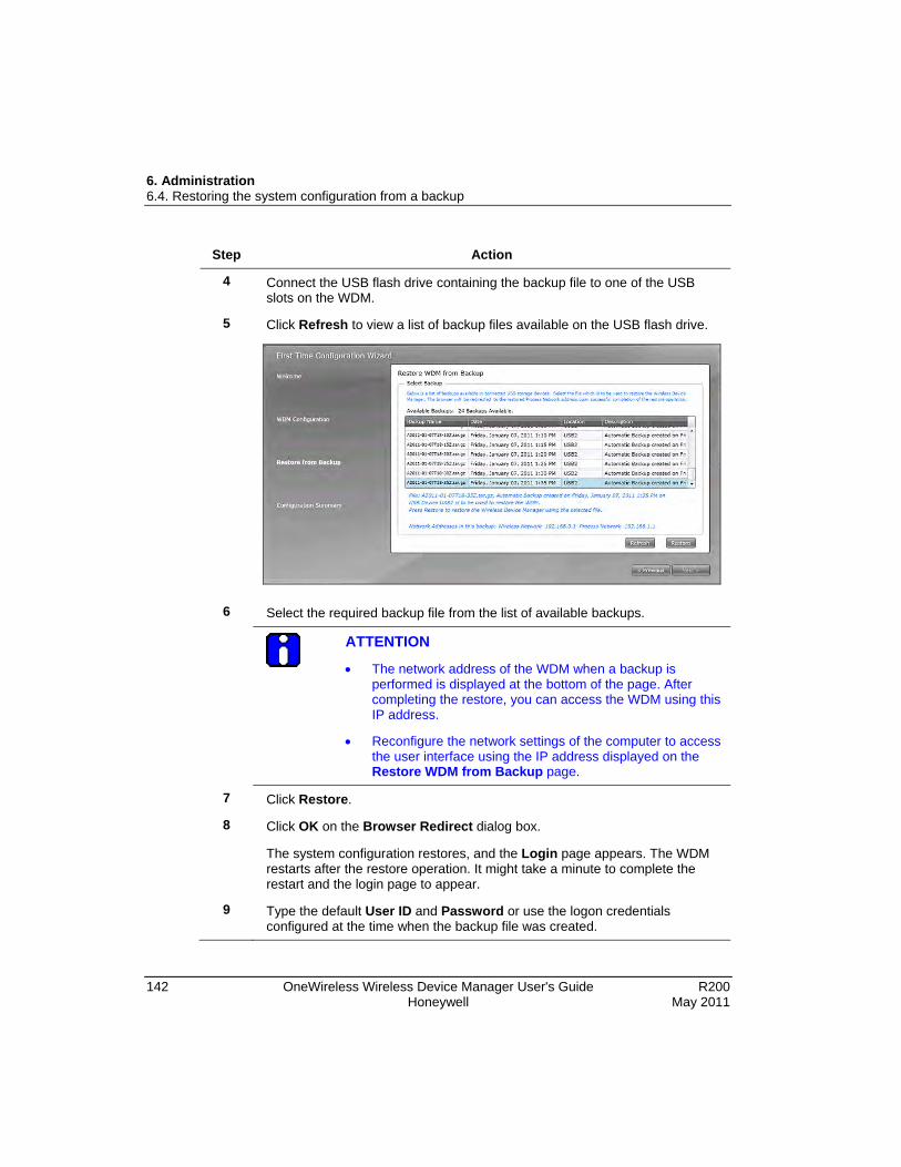
6. Administration 6.4. Restoring the system configuration from a backup
142 OneWireless Wireless Device Manager User's Guide R200 Honeywell May 2011
Step Action
4 Connect the USB flash drive containing the backup file to one of the USB slots on the WDM.
5 Click Refresh to view a list of backup files available on the USB flash drive.
6 Select the required backup file from the list of available backups.
ATTENTION
• The network address of the WDM when a backup is performed is displayed at the bottom of the page. After completing the restore, you can access the WDM using this IP address.
• Reconfigure the network settings of the computer to access the user interface using the IP address displayed on the Restore WDM from Backup page.
7 Click Restore.
8 Click OK on the Browser Redirect dialog box.
The system configuration restores, and the Login page appears. The WDM restarts after the restore operation. It might take a minute to complete the restart and the login page to appear.
9 Type the default User ID and Password or use the logon credentials configured at the time when the backup file was created.

R200 OneWireless Wireless Device Manager User's Guide 143 May 2011 Honeywell
7. Troubleshooting and maintenance
7.1 Replacing devices You can replace a failed FDAP, Multinode, or a field device with a new device. Replace operation restores all the configuration information to the new device. This includes the position of the device on the map, device name, channel names, publication, configuration, and so on. Note that device notes from a failed device are not restored to the new device.
Considerations
• A failed device can be replaced with a new device, only if the new device specification is identical to the failed one.
• Device role should be identical for the devices that are undergoing replacement operation. That is, a field device can be replaced only with a field device and a routing field device can be replaced only with a routing field device.
• Device to be replaced should not be part of another replacement operation.
• For FDAP and field device, the radio vendor and radio model of the failed device and the new device should be identical.
• For field devices, the application vendor and application model of the failed device and the new device should be identical.
• For field devices, the number of channels and the channel types of failed device and the new device should be identical.
Prerequisites
• Ensure that the failed device is offline and that it is not deleted.
• Ensure that the new device’s tag name, type, radio vendor, and radio model is read by the WDM.
• Ensure that methods are not running for any of the channels of the new field device.
• Ensure that new device's firmware is not undergoing any upgrade operation.
• Ensure that new device's channels have been read by the WDM.

7. Troubleshooting and maintenance 7.1. Replacing devices
144 OneWireless Wireless Device Manager User's Guide R200 Honeywell May 2011
Step Action
1 Provision the new device to allow it to join the network. For more information, refer to the section Provisioning the OneWireless Network components.
2 For replacing a field device with instantiable channels, ensure that the new device’s instantiable channels are identical to that of the failed device.
If not, perform channel instantiation to make the channel configuration identical to the failed device. For more information, refer to the section Configure channel instantiation.
3 To replace a field device, set the channel to OOS mode as follows:
a) On the Selection Panel, select the field device channel.
b) On the Property Panel, expand Mode.
c) In the Target list, click OOS and then click the Apply Changed Values icon.
d) The channel icon appears as blue indicating the OOS mode.
To replace a device
4 On the Selection Panel, select the newly added device.
5 Drag the new device icon and drop it on the failed device on the map.
The Device Replacement dialog box appears.
6 Click Replace failed device <device name> with device <new device name>.
7 Click OK.
The Device Replacement Status dialog box appears indicating the progress of replace operation. The status bar also displays the status. If you close the Device Replacement Status dialog box, click the Device replacement in progress pane in the status bar to open the dialog box.
8 After the device replace operation is complete, Device Replacement Status dialog box displays the result.

7. Troubleshooting and maintenance 7.1. Replacing devices
R200 OneWireless Wireless Device Manager User's Guide 145 May 2011 Honeywell
Step Action
ATTENTION
If a device replace operation completes with errors, it implies that one or more attributes of the device is not restored successfully. In this case, manually inspect the device and channel configuration from the Property Panel, and correct any incorrectly configured attribute.
9 Click Clear List to clear the list of device replace operations.

7. Troubleshooting and maintenance 7.2. Removing devices
146 OneWireless Wireless Device Manager User's Guide R200 Honeywell May 2011
7.2 Removing devices You can remove a failed device from the network. A device that is removed can rejoin the network only if it is assigned a new provisioning key.
Considerations
• Removing an online device resets the device configuration to factory defaults. This results in the loss of provisioning data from the device.
• Removing an offline device makes the security information of the device invalid, but retains the provisioning data in the device. Though the device retains the provisioning data, it should be authenticated again to allow it to join the network.
Step Action
1 On the Selection Panel, select the device that you want to delete.
If you are deleting an online device, change the channel mode to OOS for all the channels.
2 On the Property Panel, click the Delete Selected Device icon.
The Delete Device dialog box appears.
3 Click OK to remove the device.
A dialog box with message Device Deleted Successfully appears.
4 Click OK to close the dialog box.

7. Troubleshooting and maintenance 7.3. Resetting/removing a WDM
R200 OneWireless Wireless Device Manager User's Guide 147 May 2011 Honeywell
7.3 Resetting/removing a WDM Like any other device, you can reset/remove a WDM using the Delete Selected Device icon on the Property Panel. Resetting the WDM removes all the system and configuration data and resets the WDM to factory defaults.
CAUTION
This operation results in significant changes in the system configuration. Honeywell recommends you to perform this operation only when there is a definite requirement.
The following list summarizes the changes after resetting a WDM.
• All the users, except the default user (administrator) are deleted from the WDM.
• Administrator password resets to the default password.
• FDN configuration restores to default configuration.
• Configured user accounts are deleted.
• WDM name resets to default name.
• DHCP range resets to default range.
• PCN configuration restores to default configuration.
• External NTP server configuration resets to default configuration.
Step Action
1 On the Selection Panel, select the WDM.
2 On the Property Panel, click the Delete Selected Device icon.
The Delete Device dialog box appears.
3 Click OK to delete the device.
A dialog box appears indicating that the device is deleted.

7. Troubleshooting and maintenance 7.3. Resetting/removing a WDM
148 OneWireless Wireless Device Manager User's Guide R200 Honeywell May 2011
Step Action
4 Click OK to close the dialog box.
This resets/removes the WDM.
5 Restart the Web browser to access the First Time Configuration Wizard.
You can either configure the WDM using the First Time Configuration Wizard or restore the system configuration using the latest available backup. If you are configuring the WDM using First Time Configuration Wizard, you need to transfer new provisioning keys to the Provisioning Device handheld and provision all the devices in the network.

7. Troubleshooting and maintenance 7.4. Restarting FDAPs/Multinodes/field devices
R200 OneWireless Wireless Device Manager User's Guide 149 May 2011 Honeywell
7.4 Restarting FDAPs/Multinodes/field devices
Step Action
1 On the Selection Panel, select the device to be restarted.
2 On the Property Panel, expand Device Management.
3 In the Join Command list, select Warm Restart or Restart as Provisioned.
• Warm Restart option preserves static and constant attributes data.
• Restart as Provisioned option corresponds to the provisioned state of the device in which the device only retains the data received during its provisioning.
4 Click the Apply Changed Values icon.

7. Troubleshooting and maintenance 7.5. Generating reports
150 OneWireless Wireless Device Manager User's Guide R200 Honeywell May 2011
7.5 Generating reports The OneWireless user interface enables you to generate and view various reports about connectivity, device health, and battery life of the devices in a network.
You can generate and view the following reports:
• Battery Life: This report lists all devices that require battery replacement and lists the devices with battery level less than 50%.
• Device Health Overview: This report lists all the devices with wireless network disconnection and alarms.
• Connectivity: This report lists all connections with a poor or unacceptable signal quality. The RSQI value when less than 128 results in poor or unacceptable signal quality.
Perform the following steps to view, print, and save the report.
Step Action
1 Click the Reports tab to view a list of reports.
2 In the left pane, click Reports and then click the required report.
3 Click Run Report.
The Data Preview pane displays the report.
The following is a sample illustration of the connectivity report.
4 To print the report, click Print Report.
5 To save the report in .csv format, click Export as and save the report to your system.

7. Troubleshooting and maintenance 7.6. Exporting and saving system logs
R200 OneWireless Wireless Device Manager User's Guide 151 May 2011 Honeywell
7.6 Exporting and saving system logs OneWireless user interface enables you to export and save the system logs that record information about events in the application instances. Dump System Logs option saves the system log in a .tar.gz (compressed archive) format in the system for future reference. The system logs are primarily used for debugging by Honeywell Technical Assistance Center (TAC).
Step Action
1 Click the Reports tab to view the system logs.
2 On the left pane, expand System Logs > Dump System Logs.
3 Click Run Report.
The Save As dialog box appears.
4 Save the log file. The system log files are saved in *.tar.gz format.
The Dump System Log in Progress message appears.
5 After the system log is saved, a message appears indicating that system log has been saved successfully.

7. Troubleshooting and maintenance 7.7. Reporting anomalies
152 OneWireless Wireless Device Manager User's Guide R200 Honeywell May 2011
7.7 Reporting anomalies If you encounter any errors in the OneWireless Network that you cannot resolve, you need to contact TAC. The following are required while contacting TAC for assistance.
1. Export and collect system logs. For information on exporting system logs, refer to the section Exporting and saving system logs.
2. Take a system configuration back up. For information on taking a backup, refer to the section, Configuring system configuration backup.
3. Contact TAC and provide the following.
− System logs
− The system configuration backup, if required
− Affected device tag name and the exact description of the anomaly
− Time when the anomaly occurred

7. Troubleshooting and maintenance 7.7. Reporting anomalies
R200 OneWireless Wireless Device Manager User's Guide 153 May 2011 Honeywell

Honeywell Process Solutions 1860 W. Rose Garden Lane Phoenix, AZ 85027 USA