
OneIT unctional and System Architecture Version 2.0 … · OneIT unctional and System Architecture...
73
ICT EU OneFIT 31.12.2012 OneFIT Deliverable D2.2.2/D6.4 1/73 OneFIT Functional and System Architecture Version 2.0 D2.2.2/D6.4 Project Number: ICT-2009-257385 Project Title: Opportunistic networks and Cognitive Management Systems for Efficient Application Provision in the Future Internet - OneFIT Document Type: Deliverable Contractual Date of Delivery: 31.12.2012 Actual Date of Delivery: 14.01.2013 Editor: Jens Gebert (Alcatel-Lucent) Participants: See contributors’ table Workpackage: WP2 Nature: PU 1 Version: 1.0 Total Number of Pages: 73 File: OneFIT_D2.2.2_20121231.docx Abstract This document presents the refined, final OneFIT functional and system architecture for the management and control of infrastructure coordinated opportunistic networks (ONs) as well as the most relevant building blocks, which are the "Cognitive management System for the Coordination of the Infrastructure" (CSCI) and the "Cognitive Management system for the Opportunistic Network" (CMON) . This document is an update of the OneFIT functional and system architecture described in the deliverable D2.2. This second version of D2.2 is called D2.2.2 and – for administrative reasons – has also the number D6.4. Keywords List Opportunistic networks, cognitive management, architecture, CSCI, CMON, C4MS 1 Dissemination level codes: PU = Public PP = Restricted to other programme participants (including the Commission Services) RE = Restricted to a group specified by the consortium (including the Commission Services) CO = Confidential, only for members of the consortium (including the Commission Services)
-
Upload
nguyenkhue -
Category
Documents
-
view
235 -
download
0
Transcript of OneIT unctional and System Architecture Version 2.0 … · OneIT unctional and System Architecture...

ICT EU OneFIT 31.12.2012
OneFIT Deliverable D2.2.2/D6.4 1/73
OneFIT Functional and System Architecture Version 2.0
D2.2.2/D6.4
Project Number: ICT-2009-257385
Project Title: Opportunistic networks and Cognitive Management Systems for Efficient Application Provision in the Future
Internet - OneFIT Document Type: Deliverable
Contractual Date of Delivery: 31.12.2012
Actual Date of Delivery: 14.01.2013
Editor: Jens Gebert (Alcatel-Lucent)
Participants: See contributors’ table
Workpackage: WP2
Nature: PU1
Version: 1.0
Total Number of Pages: 73
File: OneFIT_D2.2.2_20121231.docx
Abstract
This document presents the refined, final OneFIT functional and system architecture for the management and control of infrastructure coordinated opportunistic networks (ONs) as well as the most relevant building blocks, which are the "Cognitive management System for the Coordination of the Infrastructure" (CSCI) and the "Cognitive Management system for the Opportunistic Network" (CMON) . This document is an update of the OneFIT functional and system architecture described in the deliverable D2.2. This second version of D2.2 is called D2.2.2 and – for administrative reasons – has also the number D6.4.
Keywords List Opportunistic networks, cognitive management, architecture, CSCI, CMON, C4MS
1 Dissemination level codes: PU = Public
PP = Restricted to other programme participants (including the Commission Services) RE = Restricted to a group specified by the consortium (including the Commission Services) CO = Confidential, only for members of the consortium (including the Commission Services)

ICT EU OneFIT 31.12.2012
OneFIT Deliverable D2.2.2/D6.4 2/73
Executive Summary
The OneFIT project [1] is a collaborative research project for operator governed opportunistic networks (ON). These ONs are coordinated extensions of the infrastructure which can be used for example for operator governed device-to-device communication, opportunistic coverage extensions and opportunistic capacity extensions. The solution, which can also be used for Proximity Services as currently studied in 3GPP [19], provides enhanced wireless service provision and extended access capabilities for the Future Internet, through higher resource utilization, lower costs, and management decisions with a larger “green” footprint. The project derived from the fifth call for proposals of the 7th framework programme (FP7) of the European Commission for research and technological development.
This document, the version 2 of the OneFIT functional and system architecture, presents an update of the OneFIT functional and system architecture described in D2.2 [3] which was published in February 2011. Since that time, the other OneFIT workpackages have progressed on the specification of the control channels for the cooperation of the cognitive management systems, on algorithms for enabling opportunistic networks and on prototyping and validation. Based on the feedback of those workpackages, the OneFIT architecture for the management and control of infrastructure coordinated opportunistic networks (ONs) has been refined and additional procedures, e.g. related to security, are presented in this document. For administrative reasons, this document has also the number D6.4.
The most relevant building blocks for the OneFIT Functional Architecture (FA) for the cognitive management and control of infrastructure governed Opportunistic Networks are:
the Cognitive management System for the Coordination of the Infrastructure (CSCI) which is responsible for the detection of situations where an ON is useful including the ON suitability determination;
the Cognitive Management system for the Opportunistic Network (CMON) which is responsible for the creation, maintenance and termination of a given ON based on the context and policy information provided by the CSCI.
Further functionalities include the Dynamic Spectrum Management (DSM), the Dynamic, Self-Organising Network Planning and Management (DSONPM), the Joint Radio Resources Management (JRRM), and the Configuration Control Module (CCM), which are all located above the underlying Radio Access Technologies (RATs).
The System Architecture (SA) includes different options for the mapping of the OneFIT building blocks to network entities;
RAN-based distributed architecture
Core Network based centralized Architecture
Application Function based centralized Architecture
Further on, security threats are analysed and a security architecture including different security mechanisms are described.
An introduction on Control Channels for the Cooperation of Cognitive Management Systems (C4MS) including the C4MS reference model, as well as, an overview on different implementation options including IEEE 802.21, IETF Diameter, 3GPP ANDSF, 3GPP RRC, IEEE 802.11 and Distributed Agents is given.
Message Sequence Charts (MSCs) are showcased for the different OneFIT use cases. At the beginning of the MSCs, there is usually an issue detected, e.g. that a mobile terminal is out of coverage, or that parts of the network are congested. Then, the ON suitability determination is

ICT EU OneFIT 31.12.2012
OneFIT Deliverable D2.2.2/D6.4 3/73
started where other nodes can be discovered and a negotiation is made on which nodes may join an ON. The next step after a successful negotiation is the creation of the ON. During these ON establishment procedures, new links are setup and, if needed, relaying functionalities are configured.
A short overview on the OneFIT algorithms and proof-of-concept activities including links to further information is presented at the end of the document.

ICT EU OneFIT 31.12.2012
OneFIT Deliverable D2.2.2/D6.4 4/73
Contributors
First Name Last Name Affiliation Email
Jens Gebert ALUD [email protected]
Andreas Wich ALUD [email protected]
Panagiotis Demestichas UPRC [email protected]
Andreas Georgakopoulos UPRC [email protected]
Vera Stavroulaki UPRC [email protected]
Kostas Tsagkaris UPRC [email protected]
Yiouli Kritikou UPRC [email protected]
Lia Tzifa UPRC [email protected]
Nikos Koutsouris UPRC [email protected]
Dimitris Karvounas UPRC [email protected]
Marios Logothetis UPRC [email protected]
Asimina Sarli UPRC [email protected]
Aimilia Bantouna UPRC [email protected]
Louisa-Magdalene
Papadopoulou UPRC [email protected]
Aristi Galani UPRC [email protected]
Panagiotis Vlacheas UPRC [email protected]
Petros Morakos UPRC [email protected]
Alexandros Antzoulatos UPRC [email protected]
Oscar Moreno TID [email protected]
Markus Mueck IMC [email protected]
Andreas Schmidt IMC [email protected]
Christian Mouton NTUK [email protected]
Miia Mustonen VTT [email protected]
Marja Matinmikko VTT [email protected]
Marcin Filo EIT+ [email protected]
Ramon Ferrús UPC [email protected]
Oriol Sallent UPC [email protected]
Dragan Boskovic LCI [email protected]
Milenko Tosic LCI [email protected]
Paul Bender BnetzA [email protected]

ICT EU OneFIT 31.12.2012
OneFIT Deliverable D2.2.2/D6.4 5/73
Table of Acronyms
Term Meaning
3GPP 3rd Generation Partnership Project
AAA Authentication, authorization, and accounting
ANDSF Access Network Discovery and Selection Function
AP Access Point
API Application Programmable Interface
AuC Authentication Center
BS Base Station
BSF Bootstrapping Function
C4MS Control Channels for the Cooperation of the Cognitive Management System
CA Certification Authority
CCM Configuration Control Module
CCR Cognitive Control Radio
CMON Cognitive Management system for the Opportunistic Network
CPC Cognitive Pilot Channel
CSCI Cognitive management System for the Coordination of the Infrastructure
D2D Device-to-Device
DSM Dynamic Spectrum Management
DSONPM Dynamic and Self-Organizing Network Planning and Management
eNB evolved Node B
EPC Evolved Packet Core
ePDG Evolved Packet Data Gateway
ETSI European Telecommunications Standards Institute
eUTRAN evolved Universal Terrestrial Radio Access Network
FA Functional Architecture
GAN Generic Access Network
GSM Global System for Mobile communications
HLR Home Location Register
JRRM Joint Radio Resource Management
KPI Key Performance Indicator
LTE Long Term Evolution
MAC Medium Access Control
MME Mobility Management Entitiy
MSC Message Sequence Chart

ICT EU OneFIT 31.12.2012
OneFIT Deliverable D2.2.2/D6.4 6/73
NAF Network Application Function
ON Opportunistic Network
OneFIT Opportunistic networks and Cognitive Management Systems for Efficient Application Provision in the Future InterneT
P2P Peer-to-Peer
PCC Policy and Charging Control
PDN Packet Data Network
PKI Public Key Infrastructure
QoS Quality of Service
RAT Radio Access Technology
RRC Radio Resource Control
RRM Radio Resource Management
RRS Reconfigurable Radio Systems
SA System Architecture
SAP Service Access Point
SLF Subscriber Locator Function
TLS Transport Layer Security
UE User Equipment
UMTS Universal Mobile Telecommunications System
WLAN Wireless Local Area Network

ICT EU OneFIT 31.12.2012
OneFIT Deliverable D2.2.2/D6.4 7/73
Table of Contents
1. Introduction ................................................................................................................................................. 9 1.1 Summary on Scenarios..................................................................................... 9 1.2 Summary on System Requirements ................................................................. 12 2. Functional Architecture ......................................................................................................................... 13 2.1 Cognitive management System for the Coordination of the infrastructure (CSCI) ... 19
2.1.1 Missions and Services ............................................................................ 20 2.1.2 The ON-Objective ................................................................................. 20 2.1.3 The ON-blueprint .................................................................................. 21 2.1.4 Detailed functions of CSCI ..................................................................... 21
2.2 Cognitive Management system for the Opportunistic Network (CMON) ................. 23 2.2.1 Missions .............................................................................................. 24 2.2.2 Detailed functions of CMON .................................................................... 24
3. System Architecture ................................................................................................................................ 26 3.1 Elements of the OneFIT System ....................................................................... 26 3.2 Architectural Options for mapping the OneFIT elements to network entities .......... 27
3.2.1 Option 1: RAN-based distributed architecture ........................................... 28 3.2.2 Option 2: Core Network based centralized Architecture .............................. 30 3.2.3 Option 3: Application Function based centralized Architecture .................... 32 3.2.4 Optional Building Blocks ........................................................................ 35
3.3 OneFIT System Security Threats and Requirements ........................................... 37 3.3.1 Security threats .................................................................................... 38
3.4 Security Architecture and Mechanisms.............................................................. 39 3.4.1 Trusted native 3GPP Security ................................................................. 40 3.4.2 Security overlay for 3GPP and non-3GPP accesses .................................... 41
4. Control Channels for the Cooperation of the Cognitive Management System (C4MS) .... 45 4.1 C4MS layer ................................................................................................... 45
4.1.1 C4MS services ...................................................................................... 46 4.1.2 C4MS Service Access Points ................................................................... 47 4.1.3 C4MS user ........................................................................................... 47
4.2 C4MS Data Structures .................................................................................... 47 4.3 C4MS Protocol Specification ............................................................................ 48
4.3.1 C4MS implementation options ................................................................ 48 5. Message Sequence Charts ..................................................................................................................... 51 5.1 MSCs on Opportunistic coverage extension ....................................................... 51 5.2 MSC on “Opportunistic capacity extension” ....................................................... 54 5.3 MSCs on Infrastructure supported opportunistic device-to-device networking ........ 57
5.3.1 Infrastructure initiated opportunistic device-to-device networking ............... 57 5.3.2 Terminal initiated opportunistic device-to-device networking ...................... 60
5.4 MSC on opportunistic traffic aggregation in the radio access network ................... 64 5.5 MSC on opportunistic resource aggregation in the backhaul network .................... 66 6. Algorithms for enabling opportunistic networks ........................................................................ 69 7. Conclusions ................................................................................................................................................ 71 8. References .................................................................................................................................................. 72

ICT EU OneFIT 31.12.2012
OneFIT Deliverable D2.2.2/D6.4 8/73
List of Figures Figure 1: Opportunistic coverage extension scenario ............................................................................ 9 Figure 2: Opportunistic capacity extension scenario ............................................................................ 10 Figure 3: Infrastructure supported opportunistic device-to-device networking .................................. 10 Figure 4: Opportunistic traffic aggregation in the radio access network ............................................. 11 Figure 5: Opportunistic resource aggregation in the backhaul network .............................................. 11 Figure 6: OneFIT Functional Architecture for the Management and Control of infrastructure
governed Opportunistic Networks as an evolution of the ETSI/E3 FA [15] .................................. 15 Figure 7: OneFIT Functional Architecture, simplified view with combined CSCI/CMON ..................... 17 Figure 8: OneFIT Functional Architecture example where the infrastructure is not part of the ON (e.g.
Operator governed Device-to-Device communication) ................................................................ 18 Figure 9: Detailed functional view of the CSCI and CMON in the terminal .......................................... 18 Figure 10: Detailed functional view of the CSCI and CMON in the operator’s infrastructure .............. 19 Figure 11: The “legs” of an ON .............................................................................................................. 23 Figure 12: Architectural Options for mapping the OneFIT elements to network entities .................... 28 Figure 13: Mapping of the OneFIT system building blocks to the underlying network........................ 28 Figure 14: Mapping of the OneFIT system building blocks to the underlying network for the Core
Network-based centralized architecture ...................................................................................... 30 Figure 15: Location of the ON Manager for the Core Network-based centralized architecture .......... 31 Figure 16: Optional split of the ON Manager entity and additional interfaces .................................... 31 Figure 17: Mapping of the OneFIT system building blocks to the underlying network for the
centralized architecture ................................................................................................................ 32 Figure 18: Proposed architecture for Operator governed Direct Terminal to Terminal connectivity .. 33 Figure 19: Architecture Option 3 with Device based Mobile Relays, based on [23] ............................ 34 Figure 20: 3GPP Logical architecture for Policy and Charging Control (PCC) [20] ................................ 35 Figure 21: Establishing security and trust between two UEs by using 3GPP procedures..................... 41 Figure 22: High level view on the generic ON security procedures ...................................................... 42 Figure 23: System components necessary for securing UE to ON Manager communication, based on
3GPP TS 33.221 [29] and 3GPP TS33.223 [30] .............................................................................. 42 Figure 24: System components necessary for securing UE to UE communication [30] ....................... 43 Figure 25: C4MS reference model ........................................................................................................ 46 Figure 26: C4MS data structures overview ........................................................................................... 47 Figure 27: C4MS – general view ............................................................................................................ 48 Figure 28: IEEE 802.21 based C4MS message example (C4MS ON Creation Request)[12] .................. 50 Figure 29: Syntax and colour codes used in the Message Sequence Charts ........................................ 51 Figure 30: High-level MSC for Scenario 1: Opportunistic coverage extension ..................................... 52 Figure 31: High-level MSC for Scenario 2: Opportunistic capacity extension....................................... 55 Figure 32: Setup of D2D connection based on the detection of data rerouting in the PDN Gateway . 57 Figure 33: High-level MSC for Scenario 3.1: Infrastructure initiated opportunistic D2D networking . 59 Figure 34: The UE sends a request for a D2D connection to the network, which guides the setup of
the D2D connection ...................................................................................................................... 61 Figure 35: High-level MSC for Scenario 3.2: Terminal initiated opportunistic device-to-device
networking .................................................................................................................................... 62 Figure 36: High-level MSC for Scenario 4: Opportunistic traffic aggregation in the radio access
network ......................................................................................................................................... 65 Figure 37: High-level MSC for Scenario 5: Opportunistic resource aggregation in the backhaul
network ......................................................................................................................................... 67 Figure 38: Main phases in the operation of an ON and the related key functionalities ...................... 69 Figure 39: OneFIT validation platform architecture ............................................................................. 70

ICT EU OneFIT 31.12.2012
OneFIT Deliverable D2.2.2/D6.4 9/73
1. Introduction The OneFIT project [1] focuses on the infrastructure guided cognitive management of opportunistic networks (ONs). ONs are defined as temporary, operator-governed, coordinated extension of the infrastructure. ONs typically include user terminals and they can include infrastructure elements like a base station. Home Base Stations (e.g. a Home NodeB) can also be part of an ON.
This document describes the Functional Architecture (FA), the System Architecture (SA), gives an overview on the Channels Control Channels for the Cooperation of Cognitive Management Systems (C4MS) and shows Message Sequence Charts (MSCs) for the different OneFIT use cases. This document, D2.2.2 is a refined version of D2.2[3] where feedback from the work on control channels, algorithms, prototyping activities as well as related standardisation activities from 3GPP and ETSI has been incorporated.
Further on, details are given on the two most relevant building blocks which are the Cognitive management System for the Coordination of the infrastructure (CSCI) and the Cognitive Management system for the Opportunistic Network (CMON).
The architecture is based on the business scenarios, technical challenges and system requirements as described in D2.1 [2] and summarised below.
1.1 Summary on Scenarios Five different scenarios have been identified for OneFIT and described in detail in D2.1 [2]:
Scenario 1 “Opportunistic coverage extension” is for a situation in which a device cannot connect to the network operator’s infrastructure, due to lack of coverage or a mismatch in the radio access technologies. This scenario covers also the case where a device is moving out of coverage. The proposed solution shown in Figure 1 includes one or more additional connected devices that, by creating an opportunistic network, establish a link between the initial device and the infrastructure, and act as a data relay for this link.
Figure 1: Opportunistic coverage extension scenario
Scenario 2 “Opportunistic capacity extension” depicts a situation in which a device cannot access the operator’s infrastructure due to the congestion of the available resources at the serving access node. The solution shown in Figure 2 redirects the traffic through an opportunistic network to avoid the congested network segment.
Internet
Coverage of the infrastructure
Opportunistic Network
UE#1 being
out of direct coverage
UE#2BS#1
Operator’s Infrastructure
Internet
Coverage of the infrastructure
Opportunistic Network
UE#1 being
out of direct coverage
UE#2BS#1
Operator’s Infrastructure

ICT EU OneFIT 31.12.2012
OneFIT Deliverable D2.2.2/D6.4 10/73
Figure 2: Opportunistic capacity extension scenario
Scenario 3 “Infrastructure supported opportunistic device-to-device networking” shows the creation of an infrastructureless opportunistic network between two or more devices for the local exchange of information (e.g. peer-to-peer communications, home networking, location-based service providing, public safety communication, etc.). In this scenario as shown in Figure 3, the infrastructure governs the ON creation and benefits from the local traffic offloading, as well as on new service opportunities, e.g. for Proximity Services [19].
Figure 3: Infrastructure supported opportunistic device-to-device networking
Scenario 4 “Opportunistic traffic aggregation in the radio access network” describes the usage of a local opportunistic network among several devices to share a reduced number of links to the infrastructure. This solution (see Figure 4) allows some degree of traffic aggregation and caching to improve the overall network performance.
Coverage of the infrastructure
Opportunistic Network
BS#1 with high loadUE#1
UE#2
BS#2
Internet
Coverage of the infrastructure
Opportunistic Network
BS#1 with high loadUE#1
UE#2
BS#2
Internet
Internet
Coverage of the infrastructure
Opportunistic Network
Control
Cont
rol
UE#1
UE#2
BS#1
direct
device-to-device
link
Internet
Coverage of the infrastructure
Opportunistic Network
Control
Cont
rol
UE#1
UE#2
BS#1
direct
device-to-device
link

ICT EU OneFIT 31.12.2012
OneFIT Deliverable D2.2.2/D6.4 11/73
Figure 4: Opportunistic traffic aggregation in the radio access network
Scenario 5 “Opportunistic resource aggregation in the backhaul network” uses opportunistic networks to aggregate both backhaul bandwidth and processing/storage resources on access nodes. In this case, as shown in Figure 5, the ON is created over Access Points (AP) rather than user terminals, thus offering a new focus on system performance improvement.
Figure 5: Opportunistic resource aggregation in the backhaul network
All these scenarios are dependent on other devices in proximity supporting opportunistic networking mechanisms. Therefore, as analysed in more detail for the different scenarios in [44], the probability of being able to establish an ON largely depends on the range of the wireless device-to-device interface and the number of ON capable devices in a given area.
Internet
Aggregated/
Joint Link
Coverage of the infrastructure
Opportunistic Network
UE#1
UE#2
UE#3
Internet
Aggregated/
Joint Link
Coverage of the infrastructure
Opportunistic Network
UE#1
UE#2
UE#3
Coverage of the infrastructure
BS#2
BS#3
InternetNew/additional
backhaul links to
offload traffic
BS#1
New/additional
backhaul links to
offload traffic
Broken or
congested
backhaul link
Op
po
rtu
nis
tic
Net
wo
rk
Coverage of the infrastructure
BS#2
BS#3
InternetNew/additional
backhaul links to
offload traffic
BS#1
New/additional
backhaul links to
offload traffic
Broken or
congested
backhaul link
Op
po
rtu
nis
tic
Net
wo
rk
ICT EU OneFIT 31.12.2012
OneFIT Deliverable D2.2.2/D6.4 12/73
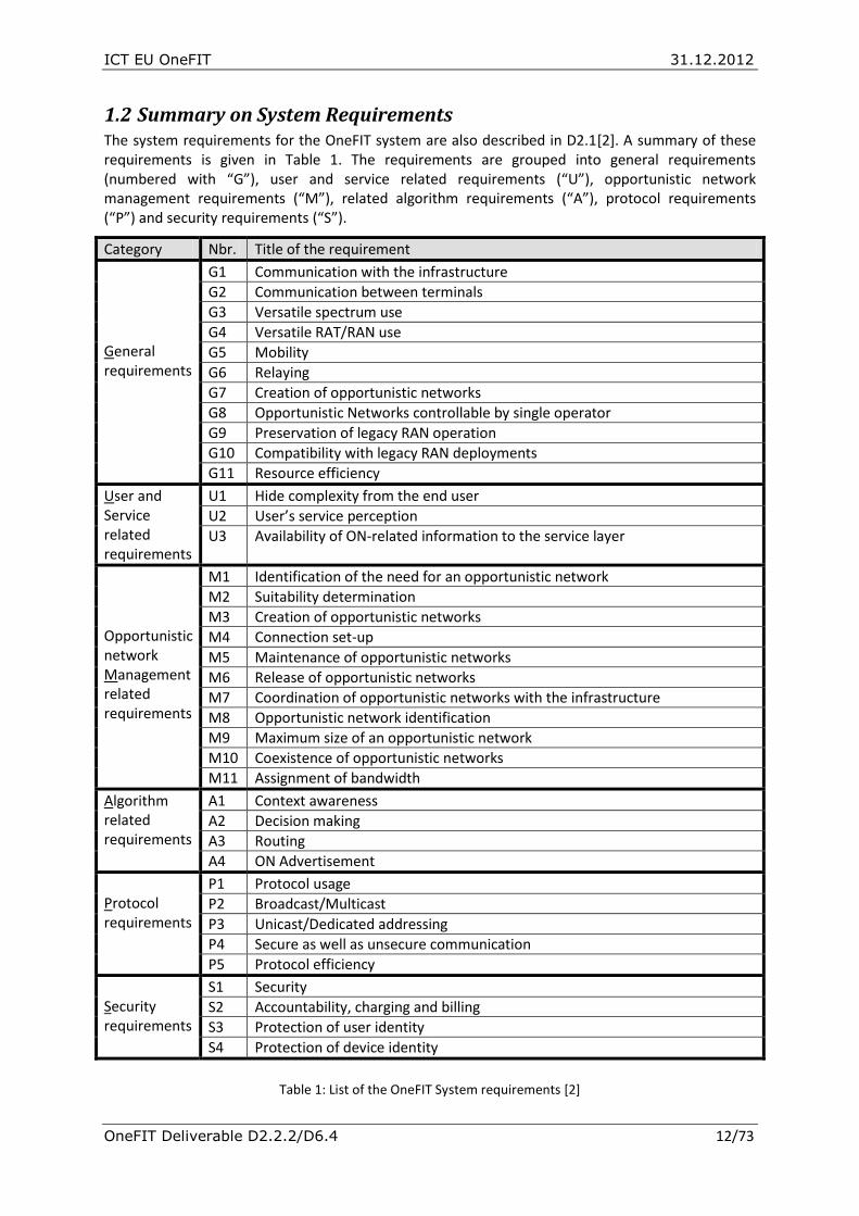
1.2 Summary on System Requirements The system requirements for the OneFIT system are also described in D2.1[2]. A summary of these requirements is given in Table 1. The requirements are grouped into general requirements (numbered with “G”), user and service related requirements (“U”), opportunistic network management requirements (“M”), related algorithm requirements (“A”), protocol requirements (“P”) and security requirements (“S”).
Category Nbr. Title of the requirement
General requirements
G1 Communication with the infrastructure
G2 Communication between terminals
G3 Versatile spectrum use
G4 Versatile RAT/RAN use
G5 Mobility
G6 Relaying
G7 Creation of opportunistic networks
G8 Opportunistic Networks controllable by single operator
G9 Preservation of legacy RAN operation
G10 Compatibility with legacy RAN deployments
G11 Resource efficiency
User and Service related requirements
U1 Hide complexity from the end user
U2 User’s service perception
U3 Availability of ON-related information to the service layer
Opportunistic network Management related requirements
M1 Identification of the need for an opportunistic network
M2 Suitability determination
M3 Creation of opportunistic networks
M4 Connection set-up
M5 Maintenance of opportunistic networks
M6 Release of opportunistic networks
M7 Coordination of opportunistic networks with the infrastructure
M8 Opportunistic network identification
M9 Maximum size of an opportunistic network
M10 Coexistence of opportunistic networks
M11 Assignment of bandwidth
Algorithm related requirements
A1 Context awareness
A2 Decision making
A3 Routing
A4 ON Advertisement
Protocol requirements
P1 Protocol usage
P2 Broadcast/Multicast
P3 Unicast/Dedicated addressing
P4 Secure as well as unsecure communication
P5 Protocol efficiency
Security requirements
S1 Security
S2 Accountability, charging and billing
S3 Protection of user identity
S4 Protection of device identity
Table 1: List of the OneFIT System requirements [2]

ICT EU OneFIT 31.12.2012
OneFIT Deliverable D2.2.2/D6.4 13/73
2. Functional Architecture The management and control functionalities for opportunistic networks have been defined as an extension to existing functionalities in today’s networks. Thus, the OneFIT Functional Architecture (FA) is an extension of an existing architecture, namely the “Functional Architecture for the Management and Control of Reconfigurable Radio Systems” as defined by ETSI in the TR 102 682 [15]. The FA in ETSI has been mainly derived from the results of the E3 research project [41].
The ETSI/E3 FA is designed for a network with heterogeneous radio access technologies where the mobile devices as well as the base stations are reconfigurable. The following features are provided by the ETSI/E3 FA:
Access Selection & Handover Decisions: Select the best radio access for a given user/session based on service requirements, radio conditions, network load, policies
Base Station Configuration and Reconfiguration to maximise the networks efficiency
Spectrum management for optimal, dynamic spectrum usage
Self-Management of the Radio Network Infrastructure
Cognition Support Mechanisms (e.g. Cognitive Pilot Channel (CPC), Spectrum Sensing).
The ETSI/E3 FA is built on top of existing Radio Access Technologies and Protocol Stacks, and therefore relies on all legacy features of operator-governed infrastructure-based networks, including credentials management, authentication, ciphering and other security-related features.
Due to the scope of the OneFit project, the following feature is added to the FA:
Opportunistic Networks Management to provide mechanisms for operator-governed ad-hoc extensions of infrastructure networks.
This infrastructure governed Opportunistic Networks Management is divided into two building blocks, namely the “Cognitive management System for the Coordination of the infrastructure” (CSCI) and the “Cognitive Management system for the Opportunistic Network” (CMON).
For the support of Opportunistic Networks, a few features need also to be added to the existing RRS/E3 FA building blocks and/or existing Radio Access Technologies (RATs), with regard to device-to-device discovery, link establishment, relay function and associated security. Some of these features are already specified in different RAT standards and are considered by the OneFIT project as implementation options.
The CSCI is mainly responsible for the activities before an ON created. This includes ON opportunity detection and ON suitability determination. The CSCI is in charge of the context acquisition, processing of the same and the determination whether or not right conditions are in place for creating the opportunistic network. When the CSCI has made a decision that an ON is suitable, the decision is then sent to the CMON.
The CMON is controlling the life cycle of the ON from creation to termination. This includes the execution of the creation procedures as well as maintenance and termination of a given ON.
A summary of this split of the functionalities for the opportunistic network coordination and management between the CSCI and CMON is shown in Table 2. The details of the functions from CSCI and CMON are explained in detail in sections 2.1 and 2.2.

ICT EU OneFIT 31.12.2012
OneFIT Deliverable D2.2.2/D6.4 14/73
CSCI CMON
Coordination with the Infrastructure (Infrastructure not necessarily part of the ON)
YES -
Coordination with other nodes in the ON - YES
Detection of situations where an ON may be useful
YES, typically based on external triggers, e.g.
information from JRRM
-
ON Suitability determination YES -
Execution of ON establishment/creation - YES
Maintenance of ON, e.g. reconfiguration - YES
Decision on termination of ON when ON is no longer suitable
- YES, typically based on external
triggers
Execution of ON termination - YES
Table 2: Functional split between CSCI and CMON
The resulting OneFIT Functional Architecture for the Management and Control of Reconfigurable Radio Systems as well as for the Management and Control of infrastructure governed Opportunistic Networks is shown in Figure 6. The main building blocks are:
(i) the Cognitive management System for the Coordination of the infrastructure (CSCI) which is responsible for the detection of situations where an ON is useful, which decides on the suitability of an ON and which provides policy and context information from the infrastructure to the ON;
(ii) the Cognitive Management system for the Opportunistic Network (CMON) which executes the creation, maintenance and termination of a given ON based on the decisions from the CSCI;
(iii) the Dynamic Spectrum Management (DSM) which provides mid- and long-term management (e.g. in the order of hours and days) of the spectrum for the different radio systems;
(iv) The Dynamic, Self-Organising Network Planning and Management (DSONPM) which provides mid- and long-term decisions upon the configuration and reconfiguration of the network or parts of it. The DSONPM decides for example on the configuration of a base station and then instructs the Configuration Control Module (CCM) in order to execute the reconfiguration;
(v) The Joint Radio Resources Management (JRRM) which performs the joint management of the radio resources across different radio access technologies. It selects the best radio access (Access-Selection & Handover Decisions) for a given user based on the session’s requested Quality of Service (QoS), radio conditions, network conditions like cell load, user preferences and network policies. The JRRM also provides Neighbourhood Information which can then be distributed via Cognitive Control Channels (CCC) or a Cognitive Pilot Channel (CPC);

ICT EU OneFIT 31.12.2012
OneFIT Deliverable D2.2.2/D6.4 15/73
(vi) The Configuration Control Module (CCM) which is responsible for executing the reconfiguration of a terminal or a base station, following the directives provided by the JRRM or the DSONPM.
These building blocks act on top of existing Radio Access Technologies (RATs).
Further on, an interface is defined between the DSM and an external geo-location database.
It should be noted here that the proposed functional blocks act in whole or in part in both network and terminal sides, as shown in the Figure 6 below.
Figure 6: OneFIT Functional Architecture for the Management and Control of infrastructure governed Opportunistic Networks as an evolution of the ETSI/E3 FA [15]
The following interfaces are used in the OneFIT Functional Architecture:
CI: Interface for the “Coordination with the Infrastructure” located between different CSCI-instances. This interface is used by the infrastructure network to inform terminals (or other infrastructure network elements) about the suitability of an ON (e.g. via an “ON-Suitability.indication message) and to provide context and policy information which are needed for the later creation and maintenance of the ON. Via this interface, the network can also collect context information from the terminals to enable the ON suitability determination. A distinction can be made between the CI-TT interface connecting the CSCI-instances of two terminals, the CI-TN interface connecting the CSCI in a terminal with the CSCI on the network side and the CI-NN interface connecting the CSCI-instances of two network entities.
OM: Interface for the “Opportunistic Management” located between different CMON-instances. Via this interface, nodes can first negotiate about the creation of an ON. During the negotiation, node capabilities and user preferences can be exchanged and the QoS capabilities of an ON can be negotiated. After the negotiation, this interface is also used for the exchange of ON-creation, ON-maintenance and ON-release messages. A distinction can be made between the OM-TT interface connecting the CMON-instances of two terminals, the OM-TN interface connecting the CMON in a terminal with the CMON on the network side and the OM-NN interface connecting the CMON-instances of two network entities (e.g. scenario 5).
JRRM
RAT 1 RAT 2 RAT n…
DSM
DSONPM
CCMCJ
MJ MC
JR CR
CS
Operator’s
infrastructure
JRRM
RAT 1 RAT n…
CCMCJ
CR JR
Relay Node (Terminal or AP)
JJ-TN
Country-wide spectrum database
Geo-location database
SS
MS
OJ
CI-TN
JRRM
RAT 1 RAT n…
CCMCJ
CR JR
Terminal CI-TT
OJOCOJOCJJ-TT
OM-TNCSCI CMON
CC OM-TTCSCI CMON
CCCSCI CMON
CC
RR-TT RR-TN
Opportunistic network
CD

ICT EU OneFIT 31.12.2012
OneFIT Deliverable D2.2.2/D6.4 16/73
CC: Interface connecting the CSCI in a node with the CMON in the same node. This interface is used e.g. to send a trigger for the creation of an ON from the CSCI to the CMON as well to provide information about the resources which can be used by the ON. Please note that this node interface will only exist if CSCI and CMON are implemented separately. In the case that CSCI and CMON are tightly integrated in one module, then there will be no explicit CC-interface in that node. A distinction can be made between the CC-T interface connecting the CMON and CSCI instances in a terminal, and the CC-N interface connecting the CMON and CSCI instances on network side;
CS: Interface between CSCI/CMON and the DSM: This interface is used by the CSCI/CMON to get information on spectrum usage and spectrum policies from the DSM. This spectrum related information can be used for the suitability determination of ONs as well as for the decision making on which spectrum shall be used in an ON. It is assumed that this interface uses identical procedures and protocols as the MS-interface;
MS: Interface between DSONPM and DSM used by the DSONPM to get information on spectrum usage and spectrum policies from the DSM. It allows DSONPM to obtain information about the available spectrum for different RATs, unoccupied spectrum bands and spectrum opportunities.
OJ: Interface between JRRM and CSCI/CMON. Although CSCI and CMON can be separated in different blocks, it is assumed that they both use the same protocol or Application Programmable Interface (API) to exchange information with the JRRM. This interface is used to trigger the JRRM for the establishment and release of radio links during the creation, maintenance and deletion of an ON. Further on, context information e.g. on available access networks or on link performance can also be exchanged via this interface. A distinction can be made between the OJ-T interface connecting the CMON/CSCI instances with the JRRM in a terminal, and the OJ-N interface connecting the CMON/CSCI instances with the JRRM on network side
CD: Interface between DSONPM and CSCI/CMON. This interface can be used by the CSCI/CMON to retrieve information on the configuration of the operator’s network.
OC: Interface between CCM and CSCI/CMON. This interface is similar to the OJ interface and may be used to obtain additional information about the current device configuration which cannot be provided by the JRRM. However, it is assumed that for the normal ON management procedures, the CCM is not involved because the CMON uses the OJ-interface to trigger link setup or release procedures.
CR: Interface between the CCM and the underlying RAT to control the reconfiguration of the radio access in a terminal or base station by the CCM;
JR: Interface between JRRM and RAT used to report information on resource status such as cell load or link measurements towards the JRRM. Further on, this interface is used for the creation, modification and release of radio links in the underlying RATs.
CJ: Interface between CCM and JRRM used by the JRRM to instruct the CCM on reconfigurations;
MJ: Interface between DSONPM and JRRM used to provide status information like cell load and other Key Performance Indicators (KPIs) from the JRRM towards the DSONPM;
MC: Interface between DSONPM and CCM used by the DSONPM to instruct the CCM on reconfigurations;

ICT EU OneFIT 31.12.2012
OneFIT Deliverable D2.2.2/D6.4 17/73
JJ: Interface between different JRRM-instances for the exchange of JRRM related information between different nodes. A distinction can be made between the JJ-TT interface connecting the JRRM-instances of two terminals and the JJ-TN interface connecting JRRM in a terminal with the JRRM on the network side;
SS: Interface between different DSM instances or between the DSM and an external geo-location database;
RR: Interface between the different RATs. This can e.g. be the interface used by a GSM, UMTS, LTE, WLAN or other protocol stack in the terminal towards a protocol stack of the same RAT in another terminal or in the network infrastructure.
The interfaces used by CSCI and CMON (CI, OM, CC, OC, OJ) are new interfaces where the details have been developed and specified in the OneFIT project. For the other interfaces (JJ, CJ, CR, JR, MJ, MC, MS, SS), the functionality can be inherited from E3 D2.3 [42].
As the CSCI and CMON need to interact closely and also because they act on the same context information, they can be integrated into one combined module so that the CC-interface disappears and the CI-interface and OM-interface will be a combined CI/OM interface as shown in the simplified view in Figure 7.
Figure 7: OneFIT Functional Architecture, simplified view with combined CSCI/CMON
In the FA as shown in Figure 6 and Figure 7, the operator’s infrastructure is always part of the ON. This is typically for scenarios like coverage extension or capacity extension.
For scenarios like opportunistic ad-hoc device-to-device networking between terminals, the infrastructure will not be part of the ON as shown in Figure 8. The infrastructure in such a case only provides assistance over the CI-TN interface, but there will be no active CMON instance in the infrastructure.
Every node which is part of the ON must have an active CMON instance while a CSCI instance is only needed in those nodes which are coordinating with the infrastructure or which participate in the ON suitability determination. Inactive CMON and/or CSCI instances are grey-coloured in Figure 8’s example.
JRRM
RAT 1 RAT 2 RAT n…
DSM
DSONPM
CCMCJ
MJ MC
JR CR
CS
Operator’s
Infrastructure
JRRM
RAT 1 RAT n…
CCMCJ
CR JR
Relay Node (Terminal or AP)
JJ-TN
Country-wide spectrum database
Geo-location database
SS
MS
OJ
CI/OM
-TN
JRRM
RAT 1 RAT n…
CCMCJ
CR JR
Terminal
CI/OM
-TT
OJOCOJOCJJ-TT
CSCI CMON CSCI CMON CSCI CMON
RR-TT RR-TN
Opportunistic network
CD

ICT EU OneFIT 31.12.2012
OneFIT Deliverable D2.2.2/D6.4 18/73
Figure 8: OneFIT Functional Architecture example where the infrastructure is not part of the ON (e.g. Operator governed Device-to-Device communication)
A more detailed functional view of CSCI and CMON is given in Figure 9 (terminal side) and Figure 10 (network infrastructure side) below and described in the following subsections.
Figure 9: Detailed functional view of the CSCI and CMON in the terminal
JRRM
RAT 1 RAT 2 RAT n…
DSM
DSONPM
CCMCJ
MJ MC
JR CR
CS
Operator’s
infrastructure
JRRM
RAT 1 RAT n…
CCMCJ
CR JR
Terminal 2
JJ-TN
Country-wide spectrum database
Geo-location database
SS
MS
OJ
CI-TN
JRRM
RAT 1 RAT n…
CCMCJ
CR JR
Terminal 1
OJOCOJOCJJ-TT
CSCI CMONCC
OM-TT
CSCI CMONCC
CSCICMONCC
RR-TT RR-TN
Opportunistic network
CD
JRRM
RAT 1 RAT 2 RAT n…
CCMCJ
CR JR
Terminal
CSCI
JJ (JJ-TT and/or JJ-TN) JRRM
CMON
CSCI CMON
OM
(OM-TT
and/or
OM-TN)
Context Management
(Network, Nodes, Links,
Applications)
Operator Policy
Acquisition
Profile Management
(user profile,
user preferences,
device capabilities)
Information Management (Common part for CSCI and CMON)
CC
CI (CI-TT and/or CI-TN)
CC
OJOC
Decision Making
RR (RR-TT and/or RR-TN)RAT n
Knowledge
Management
ON Suitability
Determination Know-
ledge
Manage-
ment
Decision Making
ON Creation,
Maintenance
&
Termination
Control
Execution of ON
establishment
Execution of ON
reconfiguration
Execution of ON
Termination

ICT EU OneFIT 31.12.2012
OneFIT Deliverable D2.2.2/D6.4 19/73
Figure 10: Detailed functional view of the CSCI and CMON in the operator’s infrastructure
2.1 Cognitive management System for the Coordination of the infrastructure (CSCI)
The CSCI - Cognitive management System for the Coordination of the infrastructure is the functional entity in charge of the context acquisition, processing of the same and the determination whether or not right conditions are in place for creating an opportunistic network.
The CSCI is responsible for the detection and evaluation of situations where an ON may be useful as part of the ON suitability determination phase. The detection for the need of an ON can also be triggered by other modules; as an example, the JRRM may detect that a device is moving out of coverage or cannot well served due to high load in a network segment, and that a traditional handover to another cell is not feasible.
The CSCI delegates the actual creation, maintenance and termination of a given ON to the associated CMON functional entity and it is located in both the operators’ infrastructure side (then called “CSCI-N”) and the terminal side (then called “CSCI-T”).
The Suitability Determination is a centralized process, with the decision making located typically in the infrastructure but in some cases (e.g. out-of-coverage scenario) located inside a device. The decision making is based on infrastructure-level information provided by functional entities in the network and user/device-level information provided by the CSCI-T entities from a selected set of devices.
The Suitability Determination runs before the creation of an ON but also during the lifetime of the ON in order to check that context changes and ON reconfigurations (information from CMON) have not cancelled the benefit/suitability of the ON.
The CSCI involves context awareness, operator policy acquisition and management and profile management which provide the input to the decision making mechanism. The cognition relies on the fact that knowledge management functional entities interact with the previously mentioned entities in order to make better decisions in the future, according to the learned results.
JRRM
RAT 1 RAT 2 RAT n…
CCMCJ
JR CR
Operator’s infrastructure
CSCI
JJ-TNJRRM
DSM
CS
CSCI CMON
OM-TN
Decision Making
ON Suitability
Determination
CC
OJ
CI-TN
CC
RR-TNRAT
CMON
Know-
ledge
Manage-
ment
Decision Making
ON Creation,
Maintenance
&
Termination
Control
Execution of ON
establishment
Execution of ON
reconfiguration
Execution of ON
TerminationKnowledge
Management
DSONPM
CD
MS
Context Management
(Network, Nodes, Links,
Applications)
Operator Policy
Acquisition & Management
Profile Management
(user profile,
user preferences,
device capabilities)
Information Management (Common part for CSCI and CMON)

ICT EU OneFIT 31.12.2012
OneFIT Deliverable D2.2.2/D6.4 20/73
Specifically, the context awareness functional entity in the infrastructure involves the monitoring of the status of the infrastructure network, in order to be aware of the necessity to create an ON. Also, node information is nested in the context entity which includes node’s capabilities, node’s status, node’s location (including information from a geo-location database), node’s mobility level and node’s supported applications. Node information is very useful in the decision making process as it provides the necessary data of the available, candidate nodes, in order to select afterwards the best of these nodes. On the other hand, the context awareness functional entity in the CSCI-T is needed in order to acquire information for the status of nodes, which then will be used as input to the decision making mechanism.
Further on, the operator’s policy derivation and management in the infrastructure side designates high level rules that should be followed in context handling. Usually, they are imposed by operators/ regulators and refer to reconfiguration strategies, such as operator’s preferences and priorities on goals to be achieved. These are related to the maximization of the QoS levels, and the minimization of cost factors (e.g. resource consumption). In the terminal side, the operator’s policy derivation and management is replaced by the policy acquisition from the operator which is responsible for acquiring the necessary policies from the CSCI in the infrastructure side.
In turn, the profile management functional entity in the CSCI includes preferences, requirements and constraints of user classes and applications which are required for the decision making. In the terminal side, the profile management functionalities are also included in order to provide details on the user class and application requirements and constraints.
In case that the conditions (dictated by the policy engine) or the potential gains by the operation of the ON are satisfied, the CSCI will come up with an ON blue print design and pass it to the CMON for the execution. To that respect, the result of the ON suitability determination phase (i.e. the request for creation of an ON) will be passed to the CMON which will handle the actual creation of the opportunistic network.
2.1.1 Missions and Services
The missions of the CSCI functional entity are:
Definition of ON objectives (including QoS and security objectives)
ON Opportunity Detection
ON Suitability Determination (incl. compliance to network policies)
Optimization of spectrum usage
The services offered by the CSCI functional entity are:
The issuing of request for information provision:
o To the existing network management entities, e.g. the DSM, HLR, etc…
o To the population of mobile terminals under coverage (for “pre-ON-setup” reports), through the RAN elements (BS)
The ON-blueprint design (see details below)
The issuing to the CMON of requests for ON creation and extension
2.1.2 The ON-Objective
The identification of the ON-Objective is necessary to the CSCI to:
Define the top-level requirements on the ON, such as QoS
Define the criteria for ON termination.

ICT EU OneFIT 31.12.2012
OneFIT Deliverable D2.2.2/D6.4 21/73
Typical ON-Objectives are:
“offload users A,B,C from BTS X to femto Y until BTS X is back to normal load condition”
“connect users A,B,C through shortest possible paths until the last-but-one disconnects from the XYZ Social Network”
2.1.3 The ON-blueprint
The ON-blueprint is designed for a given ON, meaning towards an identified ON-Objective.
The ON-blueprint is the input to the CMON process for execution of the ON creation.
The ON-blueprint is made of:
1. A set of ON-Candidate Nodes :
“Candidate” means the concerned node may or may not be eventually part of the ON, but it is part of the possible members. The final decision for inclusion during the execution of the establishment in the ON is made by the CMON entity which considers actual deployment and other optimizations (e.g. power consumption)
Candidate nodes have gone through the verification (by CSCI) of ON-related preferences
Candidate nodes have gone through the verification of “connectability” to at least one other candidate node
2. An ON-Spectrum Allowance
This allowance consists in the piece of spectrum that could be used for the ON, given the overall spectrum availability in the area and the CSCI optimization algorithm outcomes based on the ON-Objective and the considered size for the ON
The CMON entity (see section 2.2) will pick-up spectrum within the Spectrum Allowance
3. A set of QoS objectives per ON-End-user
These objectives are for ON-End-users (e.g. applications using ON capabilities), as QoS for relay nodes/links will be determined by the CMON process
These objectives are related to the entire path from each ON-End-user to the network access point (e.g. base station)
2.1.4 Detailed functions of CSCI
The CSCI is expected to include the following functions:
To manage information exchange procedures between CSCI entities on the network and terminal sides related to:
o Discovery and registration
Announcement of supported ON capabilities
Registration of CSCI-T entities with the coordinating CSCI-N
Pairing between peer CSCI-T entities of neighbouring terminals
o Context and policy information exchanges
Provision of policy information from CSCI-N to CSCI-T entities.
Exchange of context information between CSCI entities

ICT EU OneFIT 31.12.2012
OneFIT Deliverable D2.2.2/D6.4 22/73
In the case of CSCI-N, to manage access to policy and context information from network infrastructure elements by:
o Obtaining spectrum assignment policies expressing the regulatory framework and operators objectives
o Obtaining operator policies to drive ON behaviour
o Obtaining application flows characteristics (e.g., QoS parameters, application end-points)
o Obtaining ON-related user preferences
o Obtaining ON-related device capabilities
o Obtaining geo-location coordinates for involved or candidate ON devices from location services
o Obtaining measurements from radio link layers in infrastructure nodes
o Obtaining context information from specific monitoring mechanisms (e.g., local sensing through interfaces to spectrum sensors)
In the case of CSCI-T, to manage access to local context information from the terminal by:
o Obtaining measurements from device radio link layers
o Obtaining geo-location coordinates from device built-in positioning functions
o Obtaining application flows characteristics (e.g., QoS parameters)
o Obtaining ON-related user preferences
o Obtaining ON-related device capabilities
o Obtaining context information from specific local monitoring mechanisms (e.g., wide-band spectrum sensing functionality)
To support decision-making logic for:
o ON suitability determination
Security management:
o Ensure that the security mechanisms used by the underlying RAT(s) are providing the required security level from end-to-end. These security mechanisms include:
Authentication: Manage self-identity (assigned at first provision) and authentication data needed to authenticate other entities.
Protection of user identity (management of user’s aliases).
Protection of device identity (management of device’s temporary identities and association to physical addresses).
Authorization of applications (policies and permissions for applications to use services or to access data).
Protection of private data (storage of private user information and ciphering/deciphering of certain critical information, as defined by applications).
Management of configuration settings related to security such as using the device as a relaying node by others.
Accountability and billing procedures:

ICT EU OneFIT 31.12.2012
OneFIT Deliverable D2.2.2/D6.4 23/73
o Network instances of CSCI must receive authenticated notifications of ON-related services used by the end user/applications in order to properly charge the user.
o Terminal instances of CSCI must send authenticated notifications of the ON-related services used by the user of the terminal.
2.2 Cognitive Management system for the Opportunistic Network (CMON)
The CMON - Cognitive Management system for the Opportunistic Network is responsible for executing on the design obtained from the CSCI and then operationally supervising the created ON. This entity is in charge of the creation, maintenance and termination (according to the policies maintained in the CSCI) of the opportunistic network. Moreover, the CMON is responsible for the coordination of nodes in the ON. The CMON is also located in both the operators’ infrastructure and the terminal side.
Generally, the CMON in the operators’ infrastructure involves context awareness, policy acquisition and profile management which provide the input for the decision making mechanism. In the terminal side, the CMON provides functionality for the context awareness, the policy acquisition as defined by the operator and the profile management. The cognition relies on the fact that the knowledge management functional entity interacts with the previously mentioned entities in order to make better decisions in the future, according to the learned results.
In CMON, the decision-making process is a “per-leg” one: in the example below, the CMON process in the device in the middle (UE2) must take decisions for each wireless leg (A with UE1, B with Infra):
Figure 11: The “legs” of an ON
Specifically, the context awareness functional entity of the CMON in the operators’ infrastructure involves QoS assessment, in order to provide constant feedback of the ON’s experienced QoS and to initiate reconfiguration or termination procedures in case of a sudden drop of QoS. Also, application status monitoring is essential in order to know whether the application provision has ended, in order to terminate the ON. Resource monitoring is also included to the context entity in order to initiate reconfiguration or termination procedures in case of a sudden loss of resources. In other words, context awareness obtains the following: measurements from radio link layers, geo-location coordinates from device built-in positioning functions, application flows characteristics (e.g., QoS parameters), ON-related device capabilities and context information from specific monitoring mechanisms (e.g., wide-band spectrum sensing functionality). In the terminal side, the CMON provides functionality for the context awareness on the status of QoS and application flows which in turn, provide the input to the decision making mechanism.
The policy acquisition functional entity in both infrastructure and terminal sides, obtains and manages the policies which are being defined by the operator. Policies are used as input during the

ICT EU OneFIT 31.12.2012
OneFIT Deliverable D2.2.2/D6.4 24/73
decision making mechanism for selecting the most appropriate configuration, based on the user profile (preferences) and the context. More particularly, a certain policy specifies a set of rules that the CMON must follow.
The profile management functional entity involves the device capabilities and user preferences. Indicative information includes (i) the set of potential configurations (such as the Radio Access Technologies that the device is capable of operating with, the associated spectrum and transmission power levels), (ii) the set of applications/services that can be used and the sets of QoS levels associated with the use of an application/service, and (iii) the ON-related user preferences (e.g. the utility volume/ user satisfaction) associated with the use of an application/service at a particular quality level.
Further on, the decision making functionality is present in order to handle effectively the ON creation, maintenance and ON termination according to the input from the context awareness, policy acquisition and profile management functional entities. According to the derived decision, the control entity deals with issues such as the execution of ON establishment/ creation, execution of ON reconfiguration/ maintenance or execution of ON termination. To that respect, it controls whether to proceed with an ON reconfiguration as defined in the maintenance phase or initiate the handover to infrastructure and release of resources in the case of the termination. In case a reconfiguration is deemed necessary, the CCM component will be triggered to control over terminal reconfiguration capabilities. Via the JRRM entity, CMON will control over communication protocol stacks in the terminals and infrastructure nodes by managing radio layers operation (e.g., radio link setup, radio link configuration) and network layer operation (e.g., route management internal to ON and to/from infrastructure).
The contextual and performance parameters collected by the CMON during the life cycle of an ON are used for learning and improvement of its management functions/logic. Equally these data are passed onto the CSCI for improving the governance functions/logic hosted by the CSCI.
2.2.1 Missions
According to acquired operator’s policies, context awareness and profile management, the main missions of the CMON functional entity are:
Decision Making for:
o ON creation;
o ON reconfiguration;
o ON termination.
Control functionality for:
o Execution of ON establishment/ creation;
o Execution of ON reconfiguration;
o Execution of ON termination.
Knowledge management
Security management:
o Ensure that the security mechanisms used by the underlying RAT(s) are providing the required security level from end-to-end.
2.2.2 Detailed functions of CMON The CMON is expected to have the ability of managing information exchange with CSCI and other CMONs to allow the discovery of supported ON capabilities in neighbouring infrastructure nodes and

ICT EU OneFIT 31.12.2012
OneFIT Deliverable D2.2.2/D6.4 25/73
devices through capability announcement and pairing mechanisms among peer CMONs. Also, with respect to the context and policy information exchange, the CMON obtains context and policy information from the CSCI, provides context information to the CSCI, both by utilizing the CC interface, and obtains or provides context and policy information from/ to other CMONs by using the OM interface. Also, it issues commands for managing the ON operational phases (e.g., ON establishment, maintenance/ reconfiguration and termination procedures).
Additionally, the CMON manages access to local context information by obtaining measurements from device radio link layers, obtaining geo-location coordinates from device built-in positioning functions, obtaining application flows characteristics (e.g., QoS parameters), obtaining ON-related user preferences, obtaining ON-related device capabilities and obtaining context information from specific local monitoring mechanisms (e.g., wide-band spectrum sensing functionality).
The CMON-T has control over terminal reconfiguration capabilities and over the communication protocol stacks in the terminal by for example controlling of radio layers operation between terminals (e.g., radio link setup, radio link configuration) or controlling of network layer operation (e.g., route management internal to ON and to/ from infrastructure).
CMON-N has control over the establishment/modification/release of bearer services in the infrastructure network to support ON traffic.
Finally, with respect to security implementation related procedures, the CMON is expected to deal with security requirements in order to ensure that the security mechanisms used by the underlying RAT(s) are providing the required security (e.g. ciphering, deciphering and authentication). Further on, the CMON needs to provide relevant information for the accountability and billing procedures.

ICT EU OneFIT 31.12.2012
OneFIT Deliverable D2.2.2/D6.4 26/73
3. System Architecture This chapter describes the high level OneFIT system architecture which has been developed based on the system requirements, the functional architecture and the proposed scenarios and use cases.
The OneFIT system (opportunistic networks and cognitive management) will be based on a framework that is compatible with the existing network and user equipment, radio spectrum, protocols and policies:
Supported base stations will be legacy base stations, access points, femtocells and reconfigurable multi-standard base stations;
Supported user terminals will be legacy terminals, multi-standard radio terminals and cognitive radio terminals;
Spectrum considered suitable for ON applications includes unlicensed bands, licensed bands as well as secondary spectrum usage (e.g. UHF TV White Space bands). For each spectrum, the corresponding policies and rules about allowed channels, transmit power, radio access technology, modulation technique need to be followed.
Protocols that can be used by the OneFIT system are legacy protocols at different layers of a system solution as well as new protocols compatible with the legacy protocols and added in order to support different phases in the ON lifetime;
Policies and rules that have to be taken into account when building the OneFIT system are the legacy regulatory policies as well as the business policies commonly used by network operators.
3.1 Elements of the OneFIT System The OneFIT system introduces the concept of Opportunistic Networks (ON) as coordinated extensions of the infrastructure that are built on top of existing networks (operator and user equipment) and governed by the operator. These networks will be created where and when needed, for an efficient application provisioning to requesting users.
For enabling the ON concept over existing networks, the OneFIT system requires two basic building blocks:
Cognitive management systems;
Control channels for coordination and cooperation of cognitive management systems.
As cognitive management systems, the CSCI and the CMON are introduced. Their algorithms, roles and relationship have been defined during this project.
Moreover, the OneFIT system introduces the C4MS (Control Channels for the Cooperation of the Cognitive Management Systems - see chapter 4) as the main logical protocol for communication, cooperation and coordination between CSCI and CMON management entities introduced earlier. This protocol can be established over different existing radio access technologies and therefore making the OneFIT system platform/technology independent.
The CSCI and CMON building blocks shall be self-contained functional entities which can be add-ons to the existing solutions. Equally, the adopted architectural principle ensures compatibility with future radio access technologies and network elements. The system will use spectrum sensing and network/traffic monitoring techniques for gathering data required for cognitive management algorithms. Spectrum sensing will be used for gaining knowledge of available radio systems characteristics, condition and link quality estimation. This knowledge can be distributed between management systems or stored in databases that are to be used for gaining cognitive information

ICT EU OneFIT 31.12.2012
OneFIT Deliverable D2.2.2/D6.4 27/73
about spectrum usage. This will enable efficient usage of available spectrum and therefore boost system performance and reduce interference. Network/traffic monitoring will be used for obtaining knowledge about traffic patterns, user mobility levels and application requirements. This information can be exchanged between management nodes and stored in databases of cognitive data. This will enable the system to dynamically respond on different conditions in the network and improve network usage/utilisation and application provision.
Network nodes that are to be used in the ON environment must support some kind of reconfiguration of their parameters (radio access technology specific parameters). Nodes that support multiple radio access technologies have to be capable to dynamically configure their radio interfaces to the required radio access technology.
3.2 Architectural Options for mapping the OneFIT elements to network entities
The OneFIT system building blocks can reside in various elements of an underlying network.
This section describes how the building blocks of the OneFIT FA (CMON, CSCI, DSM, JRRM, ...) can be allocated across the network and mapped to the different network elements. Parts of the CSCI and CMON functions are located in the terminals as well as in the operator’s network. A difference can be made for the mapping inside the operator’s network, if the CSCI and CMON should mainly be mapped into nodes in the radio access network or if they should be located in the core network. Therefore, three different options will be presented as shown in Figure 13 and explained in the following subsections.
Option 1: RAN-based distributed architecture
Option 2: Core network-based centralised architecture
CMONCSCI
RANCN
MME
SGW PGW
InternetCMONCSCI
C4MS
RANCN
MME
SGW PGW
Internet
CMONCSCI
CMONCSCI
C4MS

ICT EU OneFIT 31.12.2012
OneFIT Deliverable D2.2.2/D6.4 28/73
Option 3: Application Function based centralised architecture
Figure 12: Architectural Options for mapping the OneFIT elements to network entities
3.2.1 Option 1: RAN-based distributed architecture
In this option as shown in Figure 13, the CSCI and CMON reside only in elements of the access network (base stations, access points and femto-cells) and in the user equipment.
JRRM
C4MS
CCM
CSCI CMON
RAT 1
RAT 2
...
RAT n
DSM
JRRM
CCM
CSCI CMON
RAT 1
RAT 2
...
RAT n
JRRM
C4MS
CCM
CSCI CMON
RAT 1
RAT 2
...
RAT n
JRRM
C4MS
CCM
CSCI CMON
RAT 1
RAT 2
...
RAT n
CCM
CSCI CMON
RAT 1
RAT 2
...
RAT n
JRRM
CCM
CSCI CMON
RAT 1
RAT 2
...
RAT n
eNB 1
eNB2DSM
JRRM
CCM
CSCI CMON
RAT 1
RAT 2
...
RAT n
HeNB
WLAN AP WLAN controller
HNB-GW
ePDG
MME
SAE Serving GW
SAE PDNGW
HSS
PCRF
HMS
Operation andManagement
CoreNetwork
Radio AccessNetwork
User Devices
UE1
UE2 UE3
CCM
CSCI CMON
JRRM
DSM
RAT specific radio connection
C4MS logical connection
JRRM
C4MS
CCM
CSCI CMON
RAT 1
RAT 2
...
RAT n
UE4
User plane
Control plane
CSCI
External Data base
Private or public WAN
CI/OM_1
CI/OM_2 CI/OM_3
CI/
OM
_4
CI/OM_1
X2
lu-hm
S1S11
S6
S5
S7
S1
lu-h
S1
WnS2
Regulationconstraints and
white spacesDatabase
CI/OM_5
C4MS
C4MS
C4MS
C4MS
C4MS
JRRM
C4MS
3GPPO&M
non-3GPPO&M
S14
ANDSF
Figure 13: Mapping of the OneFIT system building blocks to the underlying network
RAN CN
MME
SGW PGW
Internet
CMONCSCI
CMONCSCI
C4MS

ICT EU OneFIT 31.12.2012
OneFIT Deliverable D2.2.2/D6.4 29/73
The C4MS protocol between OneFIT cognitive systems is presented with blue dashed lines. These lines can present interfaces between CSCIs of different network nodes or interfaces between CMONs of different network nodes. The interface between CSCI and CMON inside the network nodes is not shown here.
The nodes are based on existing network nodes, especially on nodes used in 3rd Generation Partnership Project (3GPP) based networks. Elements and interfaces depicted in the core network correspond to the 3GPP EPC (Evolved Packet Core) network structure [22] [23].
Different options for logical and physical connections of user equipment with infrastructure nodes and among themselves are shown in Figure 13. On a logical level we have 5 different types of C4MS connections:
CI/OM_1 represents a logical connection between the CSCI/CMON in the user equipment and the CSCI/CMON in the infrastructure nodes. This interface can be used e.g. to directly request a specific application or for ON negotiation and creation.
CI/OM_2 is a connection between CSCI/CMON entities in devices where one device acts as relaying device, providing e.g. coverage or capacity extension for the other device;
CI/OM_3 is a logical connection between the CSCI/CMON in a relaying device and the CSCI/CMON in the infrastructure nodes;
CI/OM_4 represents a logical connection CSCI/CMON instances in infrastructure nodes. This type of connection is needed e.g. for ONs where devices are connected to different base stations or for backhaul resource aggregation (scenario 5 specific);
CI/OM_5 depicts a logical connection between CSCI/CMON instances in devices communicating with each other e.g. via a direct Device-to-Device (D2D) connection.
Figure 13 also depicts how the OneFIT system uses multi RAT capabilities of network nodes.
In the radio access part of the infrastructure network, the OneFIT system will be mapped onto all types of radio access devices: base stations (enhanced Node B), access points (WLAN 802.11a/b/g/n, WiMAX), femto-cells (Home enhanced Node B), etc. These devices will be able to trigger the ON suitability determination, to participate in the ON creation, to forward ON parameters to other network devices, to gather spectrum sensing and traffic monitoring data for cognitive systems and to participate in the ON termination process.
A WLAN controller is introduced in the access network in order to present the fact that the OneFIT system can also be established over 802.11 networks only (a controller can be connected to the WAN cloud directly). OneFIT building blocks are placed into the controller protocol stack if WLAN APs are “thin access points” which are only radio interfaces and all logic resides in the WLAN controller. In case of “thick APs”, the OneFIT logic can reside inside them and the WLAN controller will perform its basic functions.
Parts of the CSCI may also be located in a database in a public or an operator owned WAN cloud. Cognition related information may be stored in this data base and processed in coordination with the operator and regional/country wide policies and rules on spectrum usage, application provision, QoS requirements, etc. Results of this data processing step will be a set of predefined actions and instructions how the system should react to detected changes in the network environment. Also, responses to earlier encountered triggers for ON creation will be faster. CSCI is depicted as part of this database in order to represent the fact that this data base will be able to receive cognition related information from CSCI blocks of other network nodes but will not be part of ONs (no CMON block).

ICT EU OneFIT 31.12.2012
OneFIT Deliverable D2.2.2/D6.4 30/73
3.2.2 Option 2: Core Network based centralized Architecture In this architecture option, the central point of the ON management in the operator’s network is the ON Manager entity located in the Core Network as shown in Figure 14. This entity is hosting CSCI and CMON entities, in charge of decision making and procedures for the ON management.
Figure 14: Mapping of the OneFIT system building blocks to the underlying network for the Core Network-based centralized architecture
JRRM
CCM
CSCI CMON
RAT 1
RAT 2
...
RAT n
JRRM
CCM
CSCI CMONRAT 1
RAT 2
...
RAT n
JRRM
CCM
CSCI CMON
RAT 1
RAT 2
...
RAT n
JRRM
CCM
CSCI CMON
RAT 1
RAT 2
...
RAT n
CCM
RAT 1
RAT 2
...
RAT n
JRRM
CCM
RAT 1
RAT 2
...
RAT n
eNB 1
eNB2
DSM
JRRM
CCM
RAT 1
RAT 2
...
RAT n
HeNB
WLAN AP WLAN controller
HNB-GW
ePDG
MME
SAE Serving GW
SAE PDNGW
HSS
PCRF
CoreNetwork
Radio AccessNetwork
User Devices
UE1
UE2
UE3
CCM
JRRM
RAT specific radio connection
C4MS logical connection
JRRM
CCM
CSCI CMON
RAT 1
RAT 2
...
RAT n
UE4
User plane
Control plane
Private or public WAN
X2
S1S11
S6
S5
S7
S1
lu-h
S1
WnS2
Regulationconstraints and
white spacesDatabase
JRRM
CI/OM_1 DSONPM
CI/OM_2
ON Mgr
CI/OM_1
CI/OM_1
CI/OM_1
CI/OM_2
HMS
Operation andManagement3GPP
O&M
non-3GPPO&MANDSF
CSCI
External Data base
C4MS
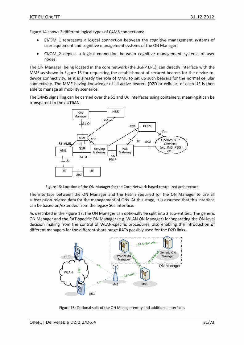
ICT EU OneFIT 31.12.2012
OneFIT Deliverable D2.2.2/D6.4 31/73
Figure 14 shows 2 different logical types of C4MS connections:
CI/OM_1 represents a logical connection between the cognitive management systems of user equipment and cognitive management systems of the ON Manager;
CI/OM_2 depicts a logical connection between cognitive management systems of user nodes.
The ON Manager, being located in the core network (the 3GPP EPC), can directly interface with the MME as shown in Figure 15 for requesting the establishment of secured bearers for the device-to-device connectivity, as it is already the role of MME to set up such bearers for the normal cellular connectivity. The MME having knowledge of all active bearers (D2D or cellular) of each UE is then able to manage all mobility scenarios.
The C4MS signalling can be carried over the S1 and Uu interfaces using containers, meaning it can be transparent to the eUTRAN.
Figure 15: Location of the ON Manager for the Core Network-based centralized architecture
The interface between the ON Manager and the HSS is required for the ON Manager to use all subscription-related data for the management of ONs. At this stage, it is assumed that this interface can be based on/extended from the legacy S6a interface.
As described in the Figure 17, the ON Manager can optionally be split into 2 sub-entities: The generic ON Manager and the RAT-specific ON Manager (e.g. WLAN ON Manager) for separating the ON-level decision making from the control of WLAN-specific procedures, also enabling the introduction of different managers for the different short-range RATs possibly used for the D2D links.
Figure 16: Optional split of the ON Manager entity and additional interfaces
S Gi
PCRF
Gx
S6a
HSS
Operator ' s IP Services
(e.g. IMS, PSS etc.)
S1 - U
S1 - MME
S5 PMIP
Rx
PDN Gateway
MME S11
S10
Gxc
Serving Gateway
S Gi
PCRF
Gx
S6a
HSS
Operator ' s IP Services
(e.g. IMS, PSS etc.)
S1 - U
S1 - MME
S5 PMIP
Rx
PDN Gateway
MME S11
S10
Gxc
Serving Gateway
ON Manager
S1-O
HSS eNB
UE UE
Uu
Ued
eNB
Generic ON
Manager
Uu
UuUed
S1-M
MEW
LAN
S1-MME
MME
WLAN ON
Manager
S1-ONWLAN
WLAN
UE1
UE2
S1-
ONM
ME
ON Manager

ICT EU OneFIT 31.12.2012
OneFIT Deliverable D2.2.2/D6.4 32/73
Then the S1-O interface appearing in Figure 15 is effectively the unified view of interfaces S1-MMEWLAN and S1-ONMME in Figure 17.
These interfaces have been described in D3.3 Annex II [7]section 2.3.2 and 2.3.4.
With regards to the Ued interface, it is a generic interface that can be implemented using any short-range radio technology, typically 802.11 infrastructure mode, adhoc mode or WiFi Direct mode.
3.2.3 Option 3: Application Function based centralized architecture
In this option, the ON Manager hosting the CSCI and CMON functions in the operator's network can be seen as an Application Function having a direct logical interface towards the user devices. The ON manager can be seen as a function similar to the 3GPP Access Network Discovery and Selection Function (ANDSF) [32] that can be populated with information provided by the network operator as well as by Users.
Figure 17: Mapping of the OneFIT system building blocks to the underlying network for the centralized architecture
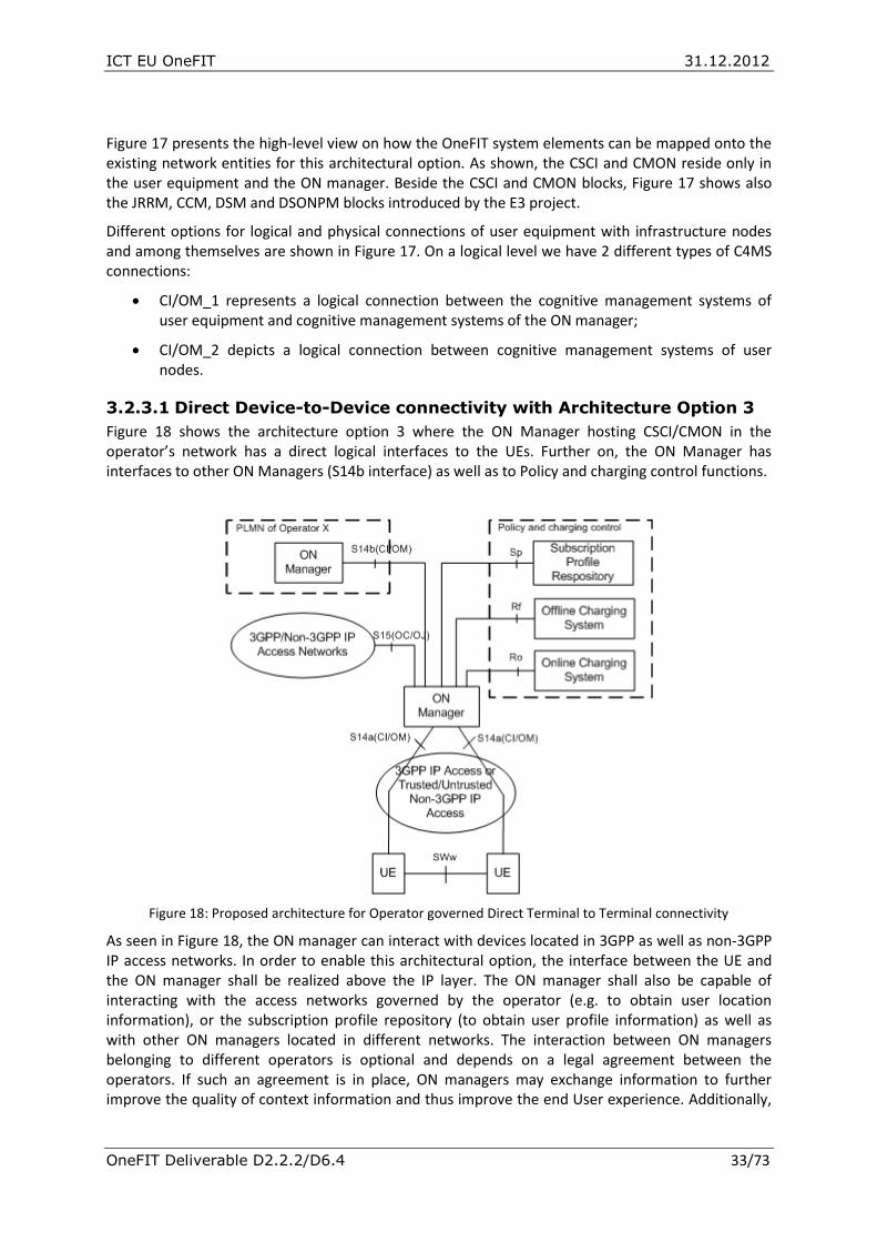
ICT EU OneFIT 31.12.2012
OneFIT Deliverable D2.2.2/D6.4 33/73
Figure 17 presents the high-level view on how the OneFIT system elements can be mapped onto the existing network entities for this architectural option. As shown, the CSCI and CMON reside only in the user equipment and the ON manager. Beside the CSCI and CMON blocks, Figure 17 shows also the JRRM, CCM, DSM and DSONPM blocks introduced by the E3 project.
Different options for logical and physical connections of user equipment with infrastructure nodes and among themselves are shown in Figure 17. On a logical level we have 2 different types of C4MS connections:
CI/OM_1 represents a logical connection between the cognitive management systems of user equipment and cognitive management systems of the ON manager;
CI/OM_2 depicts a logical connection between cognitive management systems of user nodes.
3.2.3.1 Direct Device-to-Device connectivity with Architecture Option 3
Figure 18 shows the architecture option 3 where the ON Manager hosting CSCI/CMON in the operator’s network has a direct logical interfaces to the UEs. Further on, the ON Manager has interfaces to other ON Managers (S14b interface) as well as to Policy and charging control functions.
Figure 18: Proposed architecture for Operator governed Direct Terminal to Terminal connectivity
As seen in Figure 18, the ON manager can interact with devices located in 3GPP as well as non-3GPP IP access networks. In order to enable this architectural option, the interface between the UE and the ON manager shall be realized above the IP layer. The ON manager shall also be capable of interacting with the access networks governed by the operator (e.g. to obtain user location information), or the subscription profile repository (to obtain user profile information) as well as with other ON managers located in different networks. The interaction between ON managers belonging to different operators is optional and depends on a legal agreement between the operators. If such an agreement is in place, ON managers may exchange information to further improve the quality of context information and thus improve the end User experience. Additionally,

ICT EU OneFIT 31.12.2012
OneFIT Deliverable D2.2.2/D6.4 34/73
in order to enable charging, the ON manager shall be able to interact with Online and Offline Charging System (see [26] on charging in 3GPP).
3.2.3.2 Relaying Devices with Architecture Option 3
3GPP standardized different approaches for the interworking of non-3GPP technologies with legacy 3GPP technologies with the main purpose to extend the 3GPP network coverage by enabling access to 3GPP services over non-3GPP Access Networks (ANs) such as WLAN ANs. These approaches include
GAN (Generic Access Network) [33],
I-WLAN (Interworking WLAN) [21],
Untrusted/Trusted Non-3GPP IP Access [23] .
These approaches allow the 3GPP network operators to
1) maintain control over authentication, accounting, charging and billing,
2) provide seamless mobility between different systems.
This section proposes to extend the 3GPP based concepts of interworking to support user terminals which temporarily act as a relaying device (using e.g. their short range radio interfaces for coverage extension, capacity extension or device-to-device communication).
Figure 19: Architecture Option 3 with Device based Mobile Relays, based on [23]
The proposed architecture for terminal device based mobile relays, due to security reasons (i.e. existence of SWa and SWu interfaces), is based on the architecture for Untrusted non-3GPP IP access [23]2. As seen in Figure 19, the architecture reuses network elements used in the original 3GPP architecture, and proposes a new network element called UE-Relay (i.e. User terminal that
2 It needs to be underlined here that a similar architecture based on I-WLAN architecture
can be provided for pre-release 8 3GPP networks

ICT EU OneFIT 31.12.2012
OneFIT Deliverable D2.2.2/D6.4 35/73
temporarily acts as an access network). It needs to be underlined here that although Relay 1) provides access to the network over a radio link rather than over a fixed line (such as DSL) and 2) does not necessarily maintain a continuous connection to the network, it can be perceived by the network operator as well as User terminals as an access network (in this case Untrusted non-3GPP access network). Similarly to the architecture presented in the previous section, User terminals as well as Relays (i.e. User terminals which act as an access networks) may interact with the ON manager which governs and supports the creation and management of Opportunistic Networks via 3GPP and non-3GPP IP access networks.
3.2.4 Optional Building Blocks
In order to have the OneFIT system recognized and accepted by the network operators, additional building blocks can be used to address specific demands for security, trust establishment, accounting and charging policies. Some of these policies can be legacy and some of them have to be introduced by OneFIT.
3.2.4.1 OneFIT system accountability, charging and billing
The OneFIT system shall base its accounting and charging on operator policies. A special rewarding system for relaying user nodes can be used [2].
The rewarding system could be based on functionalities of the Policy and Charging Control (PCC) for non-3GPP accesses delivered by the EPC. The logical architecture of the 3GPP Policy and Charging Control is shown in Figure 20. According to [20], the PCC shall support charging models based on the volume of transmitted data, time, events, etc. One of the features of particular interest to OneFIT is the support for the “shared revenue services” for which “settlement for all parties shall be supported, including the third parties that may have been involved providing the services”. The implementation of PCC would then enable the realization of the business model in which relaying nodes receive a pay-off for providing the relaying services.
Figure 20: 3GPP Logical architecture for Policy and Charging Control (PCC) [20]
The realization of the EPC/PCC based rewarding system would require:
Identification if a user is participating in an ON
Identification if a user is providing support to other users, e.g. by relaying traffic of other users (type of support, amount of relayed data, etc.)
Type of rewarding scheme the user is participating in
Minor system modifications as described in more detail below

ICT EU OneFIT 31.12.2012
OneFIT Deliverable D2.2.2/D6.4 36/73
The introduction of the EPC based rewarding requires all the participants to be authenticated and authorized within the EPC. This can be achieved by enforcing all ON nodes that need traffic relaying to consider potential relays (i.e. other ON nodes) as untrusted non-3GPP IP access and follow the attachment procedure specified in [23] to connect and authenticate within the EPC. The alternative approach would be here to consider the relaying nodes as trusted non-3GPP IP access but due to the security reasons and terminal complexity it was decided not to consider this approach (the relaying terminal in such a case would be additionally responsible for mobility management and authentication process).
The minor system modifications mainly concern the Evolved Packet Data Gateway (ePDG) and are necessary to allow the ePDG to be responsible for:
Obtaining the identity of the relaying node – the procedure is required as the EPC system needs to know which user should receive the reward for providing the relaying service.
Confirming the successful authentication of the node requesting the access to the relaying node – the procedure is required as the relaying UE needs to know if it should allow the requesting UE to transmit data. It is worth noting here that the concept is based on the assumption that the relaying node allows for an initial access to enable the authentication of the requesting node within the EPC (the relaying node could have a list of ePDG addresses and thus determine if the requesting UEs tries to access ePDG to authenticate within EPC or access other address).
Modification of the PCC policies for the relaying node – the procedure is necessary in case the relaying UE is charged for the amount of transferred data (the procedure could decrease the charging rate, etc.).
Obtaining the identity of the relaying node as well as sending confirmation about the authentication result to the relaying node seems to be straight forward (ePDG knows the IP address of the relaying UE and can use it to determine the user identity). The modification of the PCC policies may be however more challenging.
Having the identity of the user which relays the data (determined by the ePDG) and the identity of the user which requested the access, the charging system can determine the amount of transferred data (EPC monitors the amount of transferred information in the PDN Gateway) and accordingly reward the relaying user using the concept of the “shared revenue services”. It is worth noting here that the employment of the “share revenue services” concept in such a scenario may require some changes in the existing Online or Offline Charging System implementation.
3.2.4.2 OneFIT system spectrum sensing and traffic monitoring
Efficient spectrum sensing and network monitoring techniques have to be used by the OneFIT system in order to enable fast and accurate gathering of cognition related data and to enable the system to, as fast as possible, react to dynamic changes in the network environment.
The following spectrum sensing techniques are to be considered: waveform-based sensing, cyclostationarity-based sensing, radio identification-based sensing, TV white space detection, cooperative sensing methods, etc.
One radio interface of the infrastructure nodes could be dedicated only for spectrum sensing on different frequencies. In this way, the system will have a most realistic picture of the current state of the target spectrum. User nodes could be performing spectrum sensing in pauses between data transmissions or in some other way but battery life of user equipment is the limiting factor. Dedicated hardware for sensing can be deployed in the network.
Network monitoring will be used for surveying traffic across radio links, detecting QoE (Quality of Experience for users) and QoS, network link utilisation and performance, etc. The monitoring can be

ICT EU OneFIT 31.12.2012
OneFIT Deliverable D2.2.2/D6.4 37/73
Router based (SNMP, NetFlow, Remote monitoring, etc.) or non-Router based (active (ping, traceroute) and passive).
Some new metrics will be used in order to address specifics of the OneFIT system performance evaluation. These metrics will address: link availability, packet delay, packet jitter, packet reordering, packet loss, bandwidth measurements (capacity, achievable throughputs).
3.3 OneFIT System Security Threats and Requirements Operator governed opportunistic networking will be recognized, accepted and introduced to the market by the network operators only if it addresses specific demands for trust establishment, security, as well as accounting and charging. In the following section we intend to provide a comprehensive solution for securing ONs which is based on the existing and commonly used protocols and frameworks. Securing ONs is important and necessary to protect operator's assets as well as user's assets.
During the ON suitability determination phase, the CSCI is responsible to check whether the requested (by application) level of security can be provided by the underlying layers (RAT). If security cannot be provided by underlying layers, then the CSCI/CMON and C4MS have to provide the requested level of security (trust establishment and data encryption) before the ON suitability phase results in positive answer.
The security and trust establishing system as used by the underlying RATs and/or the OneFIT building blocks shall include state of the art and legacy security protocols and mechanisms for trust establishment between different network nodes and encryption of exchanged data.
Specific concepts related to secure trust establishment between users and between users and infrastructure entities are:
Certificate: This is a public key signed by a CA (Certification Authority). By signing a public key, a CA delivers a certificate, meaning that the CA certificates that an entity is who it says it is. When an entity sends his certificate to another entity, the receiver can validate the certificate checking it against the certificate of the CA;
Public Key Infrastructure (PKI): a PKI is an architecture of authentication based on public-private keys and certification authorities;
Identity: In PKI’s context, an identity is supported by a certificate;
Public Key: Every entity must have a public key that can be sent to other ones. If talking about authentication, a challenge could be used to authenticate the other end, checking the result of the challenge with the help of the public key. If talking about encryption, the public key of A could be used by others to encrypt information only wanted to be read by A;
Private Key: Every entity must have a private key that always must be kept private. It is only used for authenticating itself, to calculate the result of a challenge, or for deciphering information ciphered before using his public key;
Certification Authority (CA): It is the trustworthy point of the PKI. Every entity must trust the CA. The CA signs the certification requests made by other entities after a procedure of identification;
Public-Private key pair: In PKI, every entity has a public and a private key.
Each node in the ON or in the infrastructure needs to be identified uniquely. There must be, for instance, a way to verify that an entity is what it says it is. A good starting point is to use a PKI infrastructure: there is a CA that signs every identity of each entity. An entity identifies itself to other entities by using its certificate (a public key that was signed by the CA). Each entity could verify the

ICT EU OneFIT 31.12.2012
OneFIT Deliverable D2.2.2/D6.4 38/73
trust of an identity by checking its certificate against the certificate of the CA (every entity must have a copy of the CA’s certificate).
Every node will have a certificate (public key signed by the CA) and a private key. The private key will be used to sign packets of the protocol (to certify the issuer of the message). The public key will be used by other entities to verify the sender of a message.
After the first access of the device to the infrastructure, it is associated a temporary identity (for instance, a new public-private key with a random validity period). This will protect the device against spoofing threats and external unauthorized identification.
3.3.1 Security threats
A typical ON scenario is characterized by the existence of multiple mobile devices which may spontaneously interact between each other. In such scenarios no trust relationship (i.e. no pre-shared secret) can be assumed to be granted between communicating parties.
The following section aims at identifying security threats which may emerge as a result of ON usage. The identified threats extend and complement the analysis provided in [18] and [31].
3.3.1.1 Assumptions for security threat identification
The threat analysis is based on the following assumptions:
Each User device is employed with a removable USIM (Universal Subscriber Identity Module) enabling authentication between itself and the network (USIM stores user's credentials that are shared only among user and Home Subscriber Server on the infrastructure side).
Users credentials stored in the USIM are not exchanged in unencrypted forms (only key materials created during authentication may be transmitted).
Connection between User/Relay and infrastructure network is assumed to be secured.
Network elements (e.g. Base Stations) which are a part of the operator's infrastructure are assumed to be secure and may not be compromised by a potential attacker.
Connections between network elements which are a part of operator's infrastructure are assumed to be secure.
Accounting, Charging and Billing is handled and controlled by the network operator
3.3.1.2 Security threat identification
Taking into account the above mentioned assumptions and characteristics of a typical ON scenario, the following threats were identified:
Unauthorised access to user or control data: 1) Malicious Users may eavesdrop user and control data on the short range radio interface, 2) Malicious Users which act as Relays may access relayed user and control data.
Manipulation of user or control data: 1) Malicious Users may modify, inject or delete user and control data on the short range radio interface, 2) Malicious Users which act as Relays may modify, inject or delete relayed user and control data.
Unauthorized access to services: 1) Malicious Users may exploit Relay's connectivity to gain free access to network, 2) Malicious Users which act as Relays may exploit User's authorised access to gain free access to network, 3) Malicious Users may impersonate another User to obtain access to local services provided by other Users
Denial of service: 1) Malicious Users which act as Relays may deny access to network services by blocking User and Control traffic, 2) Malicious Users may prevent user and

ICT EU OneFIT 31.12.2012
OneFIT Deliverable D2.2.2/D6.4 39/73
control traffic from being transmitted by inducing protocol failures, 3) Malicious Relays may impersonate an ON manager to feed User with incorrect information
3.3.1.3 Protection of private data
A security function located typically at the interface between the application layer and the infrastructure must provide functionalities to cipher those data packets as instructed by the application level. The application would only concern about which of the data elements must be protected, but not how they are protected or which algorithm has been used to do that.
The protocols used for the management of opportunistic networks shall support integrity, e.g. by inclusion of an integrity check signature in those messages where needed. This signature should be based on a key and the contents of the message, and the key should be known only by those devices involved in the communication (sender, receiver and, probably, intermediates of the communication).
The integrity mechanism used should be such that a device couldn’t be a target of a Denial of Service attack. The calculation of such integrity signatures should involve an appropriate amount of processing power (limited as it is in mobile devices).
3.3.1.4 Protection of user identity
User and node identity must be different. Applications should be able to know a temporary identifier of the identity of the user, but not the real identity of him. Although the infrastructure knows the real identity, the application would use an alias or a temporary identifier. It is up to the user whether he wants to use a real identity or an alias for each application or service.
3.4 Security Architecture and Mechanisms The following section presents the security architecture and security mechanisms and procedures which need to be employed in order to address the above mentioned security threats. In order to reach the same level of security as the current 3GPP networks, the following security requirements need to be met:
Mutual authentication of communicating parties.
Integrity and confidentiality protection of user and signalling data.
Protection of user and signalling data against replay attacks.
User identity privacy.
Relay shall be able to verify that the user is authorized to access its service.
Two solutions have been identified as possible implementation options to support the security requirements for the OneFIT system:
A. An implementation based on the existing mechanisms specified in 3GPP RAN and EPC [27][22] for providing services to trusted “native” 3GPP mobile devices and users. This solution is applicable for the architecture options 1 and 2 and described in section 3.4.1.
B. An overlay of security, built for the management of ON and making no assumption on underlying security provided by RATs. For this solution, a security layer must be inserted between the application and the underlying RATs in order to provide security for the user data. However, due to the effort for this solution and due to the availability of security in existing networks, it is preferred to re-use existing security functions in the underlying RATs.
This option also reuses existing mechanisms specified by 3GPP to deal with untrusted non-3GPP accesses [23][24] to the EPC services by devices/users typically making use of operator-managed WLAN Access Points.

ICT EU OneFIT 31.12.2012
OneFIT Deliverable D2.2.2/D6.4 40/73
This option, which is applicable to all 3 architecture options, is described in section 3.4.2.
3.4.1 Trusted native 3GPP Security
3.4.1.1 Trusted native 3GPP security for UE-relay scenarios
For the UE-relaying scenario, the “trusted” 3GPP mechanisms” [27][22] of authentication/ciphering are applied to all ON members, regardless of the RAT in use.
The example below shows the application of these mechanisms to the opportunistic coverage extension scenario: UE#1 is out of the coverage of the infrastructure, while UE#2 is connected to the RAN/EPC.
UE#1 UE#2 eNB EPC
Discovery (beacons / probes) in Step 1,
UDP/IP in Step 2
802.11 PHY/MAC LTE PHY/MACLTE PHY/MAC
RRCRRC
NAS (includes identification/authentication)NAS (includes identification/authentication)
LTE RLC/PDCPLTE RLC/PDCP
C-p
lan
e
Network is known & trusted by UE#2
UE#2 is known & trusted by Network
Used Identity: IMSI or other temporary id assigned by the network
Network is known & trusted by UE#2
UE#2 is known & trusted by Network
Used Identity: IMSI or other temporary id assigned by the network
UE#1 is not yet trusted by UE#2 and vice-versa
UE#1 is not yet trusted by UE#2 and vice-versa
UE#1 is not yet trusted by
Network and vice-versa
UE#1 is not yet trusted by
Network and vice-versa
Step1: UE#1-UE#2 Discovery &
Step2: UE#1-UE#2 Basic link establishment
UE#1 and UE#2 are known to each other
Used Identity: SSID, P2P Device ID, MAC address ?
UE#1 and UE#2 are known to each other
Used Identity: SSID, P2P Device ID, MAC address ?
UE#2-Network (PDCP)
connection is ciphered
Used key: from SIM
UE#2-Network (PDCP)
connection is ciphered
Used key: from SIM
UE#1 UE#2 eNB EPC
Discovery (beacons / probes) in Step 1,
UDP/IP in Step 2
Discovery (beacons / probes) in Step 1,
UDP/IP in Step 2
802.11 PHY/MAC802.11 PHY/MAC LTE PHY/MACLTE PHY/MAC
RRCRRC
NAS (includes identification/authentication)NAS (includes identification/authentication)
LTE RLC/PDCPLTE RLC/PDCP
C-p
lan
e
Network is known & trusted by UE#2
UE#2 is known & trusted by Network
Used Identity: IMSI or other temporary id assigned by the network
Network is known & trusted by UE#2
UE#2 is known & trusted by Network
Used Identity: IMSI or other temporary id assigned by the network
UE#1 is not yet trusted by UE#2 and vice-versa
UE#1 is not yet trusted by UE#2 and vice-versa
UE#1 is not yet trusted by
Network and vice-versa
UE#1 is not yet trusted by
Network and vice-versa
Step1: UE#1-UE#2 Discovery &
Step2: UE#1-UE#2 Basic link establishment
UE#1 and UE#2 are known to each other
Used Identity: SSID, P2P Device ID, MAC address ?
UE#1 and UE#2 are known to each other
Used Identity: SSID, P2P Device ID, MAC address ?
UE#2-Network (PDCP)
connection is ciphered
Used key: from SIM
UE#2-Network (PDCP)
connection is ciphered
Used key: from SIM
UE#1 UE#2 eNB EPC
IP/UDP ?IP/UDP ?
802.11 PHY/MAC802.11 PHY/MAC LTE PHY/MACLTE PHY/MAC
RRCRRC
NAS (includes identification/authentication)NAS (includes identification/authentication)
LTE RLC/PDCPLTE RLC/PDCP
C-p
lan
e
Step3: UE#1-Network registration
UE#2-Nwk PDCP connection is ciphered
Used key: from SIM
UE#2-Nwk PDCP connection is ciphered
Used key: from SIM
RRC
NAS (includes identification/authentication)
Network is now known & trusted by UE#1
UE#1 is now known & trusted by Network
Used Identity: IMSI or other temporary id
assigned by network
UE#1 is not yet trusted by UE#2 and
vice-versa
UE#1 is not yet trusted by UE#2 and
vice-versa
UE#1 and UE#2 are known to each other
Used Identity: SSID, P2P Device ID, MAC
address?
UE#1 and UE#2 are known to each other
Used Identity: SSID, P2P Device ID, MAC
address?
UE#1 RRC & NAS signalling forwarded to the
network by UE#2 (The network must be able to discriminate) – no security required at this stage (tbc)
UE#1 RRC & NAS signalling forwarded to the
network by UE#2 (The network must be able to discriminate) – no security required at this stage (tbc)
UE#1 UE#2 eNB EPC
IP/UDP ?IP/UDP ?
802.11 PHY/MAC802.11 PHY/MAC LTE PHY/MACLTE PHY/MAC
RRCRRC
NAS (includes identification/authentication)NAS (includes identification/authentication)
LTE RLC/PDCPLTE RLC/PDCP
C-p
lan
e
Step3: UE#1-Network registration
UE#2-Nwk PDCP connection is ciphered
Used key: from SIM
UE#2-Nwk PDCP connection is ciphered
Used key: from SIM
RRCRRC
NAS (includes identification/authentication)NAS (includes identification/authentication)
Network is now known & trusted by UE#1
UE#1 is now known & trusted by Network
Used Identity: IMSI or other temporary id
assigned by network
Network is now known & trusted by UE#1
UE#1 is now known & trusted by Network
Used Identity: IMSI or other temporary id
assigned by network
UE#1 is not yet trusted by UE#2 and
vice-versa
UE#1 is not yet trusted by UE#2 and
vice-versa
UE#1 and UE#2 are known to each other
Used Identity: SSID, P2P Device ID, MAC
address?
UE#1 and UE#2 are known to each other
Used Identity: SSID, P2P Device ID, MAC
address?
UE#1 RRC & NAS signalling forwarded to the
network by UE#2 (The network must be able to discriminate) – no security required at this stage (tbc)
UE#1 RRC & NAS signalling forwarded to the
network by UE#2 (The network must be able to discriminate) – no security required at this stage (tbc)
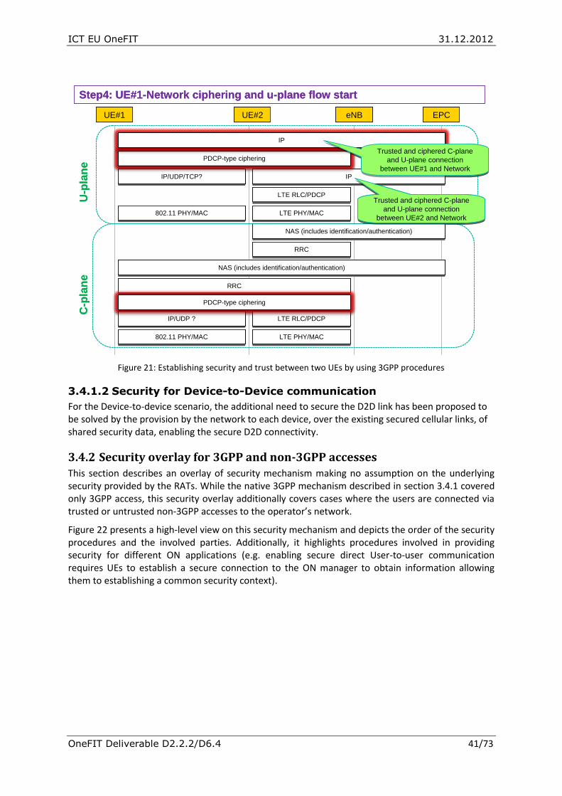
ICT EU OneFIT 31.12.2012
OneFIT Deliverable D2.2.2/D6.4 41/73
Figure 21: Establishing security and trust between two UEs by using 3GPP procedures
3.4.1.2 Security for Device-to-Device communication
For the Device-to-device scenario, the additional need to secure the D2D link has been proposed to be solved by the provision by the network to each device, over the existing secured cellular links, of shared security data, enabling the secure D2D connectivity.
3.4.2 Security overlay for 3GPP and non-3GPP accesses This section describes an overlay of security mechanism making no assumption on the underlying security provided by the RATs. While the native 3GPP mechanism described in section 3.4.1 covered only 3GPP access, this security overlay additionally covers cases where the users are connected via trusted or untrusted non-3GPP accesses to the operator’s network.
Figure 22 presents a high-level view on this security mechanism and depicts the order of the security procedures and the involved parties. Additionally, it highlights procedures involved in providing security for different ON applications (e.g. enabling secure direct User-to-user communication requires UEs to establish a secure connection to the ON manager to obtain information allowing them to establishing a common security context).
UE#1 UE#2 eNB EPC
IP/UDP ?IP/UDP ?
802.11 PHY/MAC802.11 PHY/MAC LTE PHY/MACLTE PHY/MAC
RRCRRC
NAS (includes identification/authentication)NAS (includes identification/authentication)
LTE RLC/PDCPLTE RLC/PDCP
LTE PHY/MACLTE PHY/MAC
LTE RLC/PDCPLTE RLC/PDCP
IPIP
U-p
lan
eC
-pla
ne
Step4: UE#1-Network ciphering and u-plane flow start
RRCRRC
NAS (includes identification/authentication)NAS (includes identification/authentication)
IP/UDP/TCP?IP/UDP/TCP?
802.11 PHY/MAC802.11 PHY/MAC
PDCP-type ciphering
PDCP-type ciphering
IP
Trusted and ciphered C-plane
and U-plane connection
between UE#1 and Network
Trusted and ciphered C-plane
and U-plane connection
between UE#1 and Network
Trusted and ciphered C-plane
and U-plane connection
between UE#2 and Network
Trusted and ciphered C-plane
and U-plane connection
between UE#2 and Network
UE#1 UE#2 eNB EPC
IP/UDP ?IP/UDP ?
802.11 PHY/MAC802.11 PHY/MAC LTE PHY/MACLTE PHY/MAC
RRCRRC
NAS (includes identification/authentication)NAS (includes identification/authentication)
LTE RLC/PDCPLTE RLC/PDCP
LTE PHY/MACLTE PHY/MAC
LTE RLC/PDCPLTE RLC/PDCP
IPIP
U-p
lan
eC
-pla
ne
Step4: UE#1-Network ciphering and u-plane flow start
RRCRRC
NAS (includes identification/authentication)NAS (includes identification/authentication)
IP/UDP/TCP?IP/UDP/TCP?
802.11 PHY/MAC802.11 PHY/MAC
PDCP-type cipheringPDCP-type ciphering
PDCP-type cipheringPDCP-type ciphering
IPIP
Trusted and ciphered C-plane
and U-plane connection
between UE#1 and Network
Trusted and ciphered C-plane
and U-plane connection
between UE#1 and Network
Trusted and ciphered C-plane
and U-plane connection
between UE#2 and Network
Trusted and ciphered C-plane
and U-plane connection
between UE#2 and Network

ICT EU OneFIT 31.12.2012
OneFIT Deliverable D2.2.2/D6.4 42/73
Figure 22: High level view on the generic ON security procedures
3.4.2.1 User-to-ON Manager Security
In order to secure communication between a User and an Application Function based ON Manager as described in the Architecture Option 3, a solution based on the Generic Bootstrap Architecture (GBA) [28] and a Pre-Shared Key based Transport Layer Security (TLS-PSK) [36] can be used. GBA can be defined as an authentication service which adapts existing authentication and key management procedures used in cellular networks to enable establishment of a shared key between UE and Network Application Function (in our case between UE and ON manager). The shared key obtained through GBA is further used by TLS-PSK to establish a secure connection between communicating parties. As mentioned in [28], [30], the solution enables mutual authentication, integrity protection, confidentiality protection and user identity privacy. Figure 23 depicts system components which are necessary to enable application of the proposed solution. Besides the User Equipment (UE), these system components are the Home Subscriber Server (HSS), the Subscriber Locator Function (SLF), the Bootstrapping Server Function (BSF) and the ON Manager as a Network Application Function (NAF). As mentioned in [32], the solution is also applied to enable secured communication between UE and ANDSF.
Figure 23: System components necessary for securing UE to ON Manager communication, based on 3GPP TS 33.221 [29] and 3GPP TS33.223 [30]

ICT EU OneFIT 31.12.2012
OneFIT Deliverable D2.2.2/D6.4 43/73
3.4.2.2 User-to-User security
In order to secure direct communication between users in a typical ON scenario (i.e. no pre-shared secret between communicating users) we use public key certificates which are further employed by TLS [38], IPsec [37] or a link layer solution (e.g. IEEE 802.11i [34]). Additionally, to enable secure, flexible and cost efficient creation and distribution of certificates, we use GBA based application called Support for Subscriber Certificates (SSC) [29]. In general, SCC enables the network operator to secure interaction between user/subscriber and the Network Application Function called Public Key Infrastructure (PKI) portal which performs function of the PKI Registration Authority (i.e. it authenticates certification requests based on the user's cellular subscription) and (optionally) the Certification Authority (i.e. it issues certificates based on the certification request). The certificate obtained using SSC is called subscriber certificate and contains subscribers own public key and possibly other information (e.g. subscriber's identity3).
Figure 24: System components necessary for securing UE to UE communication [30]
Figure 24 depicts the system components necessary to enable SSC (it is worth to underline here that in order to limit the number of bootstrapping procedures the PKI portal can be collocated with the ON manager).
3.4.2.3 Relay security
In order to secure relay operation, mobile devices acting as relays shall act as network authenticators (i.e. they shall require Users to authenticate prior to granting access to a network). Such approach shall prevent malicious users from interfering with the operator's charging mechanisms and accessing the EPS at the expense of relays (malicious users could try to hide the fact that they access the EPS over relays to use cheaper tariffs4). More specifically, the approach shall enable relays to 1) inform the network operator about their identity, 2) determine whether users are authorized to access the EPS over relays, and 3) ensure that Users shall be properly charged by the Network Operator. In order to secure the exchange of authentication information between the relay and the 3GPP AAA server/proxy and to maintain the same level of security as between WLAN AN and 3GPP AAA server/proxy (see [28]), relays shall establish an IPsec tunnel over SWa using public key certificates obtained via SSC (no need for pre-installed PKI certificates). Before the IPsec tunnel establishment between Relay and 3GPP AAA server/proxy, a local User-to-Relay authentication could be performed to prevent malicious users from initiating a large number of authentication attempts using different forged identities (which may lead to a faster drain of
3 In order to ensure User Identity Privacy, only temporal user identities shall be used in subscriber certificates in ON scenarios. 4 Network operators could introduce special/higher tariffs for Users accessing the EPS over Relays which enable to compensate Relays for resources consumed on relaying (e.g. battery power or bandwidth). Implementation details of such tariffs are out-of-scope of this document.

ICT EU OneFIT 31.12.2012
OneFIT Deliverable D2.2.2/D6.4 44/73
relay's battery power or may increase relay's bill). Such authentication shall be based on subscriber certificates and does not require communication with a 3GPP AAA server, allowing Relays to validate Users' identity locally.
3.4.2.4 User-to-Network security over a relay
In order to secure communication between the user and network over a relay (e.g. to prevent relays from accessing user's data), security mechanisms developed for the untrusted Non-3GPP IP access (as specified in [32]) shall be reused. The mechanisms are based on the usage of EAP-AKA and IKEv2 and enable establishment of a secure IPsec tunnel between User and ePDG. It needs to be underlined here that Relays shall allow Users to establish connections only with addresses which correspond to ePDGs that belong to their home network (the list of such addresses shall be obtained from the ON manager). This is necessary to prevent malicious Users from bypassing the network authorisation mechanisms to gain free access to network at the expense of Relays.

ICT EU OneFIT 31.12.2012
OneFIT Deliverable D2.2.2/D6.4 45/73
4. Control Channels for the Cooperation of the Cognitive Management System (C4MS)
The exchange of information, knowledge and commands between the different CMON instances as well as between different CSCI instances relies on control channels. These “Control Channels for the Cooperation of the Cognitive Management System” (C4MS)[6][8][17] can be seen as a combination and extension of the Cognitive Pilot Channel (CPC) [16] concept and the Cognitive Control Channel (CCC) concept [43] .
The CPC is a (logical and optionally in part a physical) channel, which provides information from the network to the terminals, e.g. on frequency bands, available Radio Access Technologies, and spectrum usage policies. Therefore, the CPC is a basis for the coordination between infrastructure and opportunistic networks.
The CCC is a logical channel transporting information on top of a physical channel as e.g. provided by the Cognitive Control Radio (CCR)[43] for the peer-to-peer exchange of cognition related information between heterogeneous network nodes (e.g. between terminals).
The C4MS provides a common framework integrating both concepts and thus enabling communication between terminals as well as between terminals and infrastructure networks (the employed mechanisms could be RAT specific or/and be RAT-independent). The C4MS provides communication mechanisms to:
manage operator-governed Opportunistic Networks, including mechanisms for operator-governed ad-hoc coverage extensions or capacity extensions of infrastructure networks as well as operator-governed device-to-device communication. The communication is expected to include procedures from terminal to terminal as well as between a terminal and infrastructure networks.
for the coexistence and coordination of different cognitive radio networks and nodes, operating e.g. in unlicensed bands like the ISM band or as secondary users in TV White Spaces;
These mechanisms could be radio access technology (RAT) specific or/and be RAT-independent.
The following subsections give a brief introduction to C4MS by presenting the potential services and considered C4MS components for enabling the exchange of signalling, context and policy information in heterogeneous environments.
4.1 C4MS layer The C4MS can be seen as an intermediate layer between C4MS users and the network protocol stack (see Figure 25 below) whose main role is to enable and coordinate the exchange of information between C4MS users located in different nodes. The C4MS is envisioned to enable C4MS information to be transported over different transport mechanisms (e.g. RRC, OMA DM, MIH protocol), over different layers (L2, L3 and above).

ICT EU OneFIT 31.12.2012
OneFIT Deliverable D2.2.2/D6.4 46/73
C4MS user
C4MS messages over
C-Plane (RRC, MIH (L2),
WiFi beacons)
C4MS messages over
U-Plane (UDP, TCP,
OMA DM)
C4MS user
Information
service
Message
forwarding
C4MS
discovery
C4MS C4MSC4MS-SAP
C4
MS
-NE
T-
SA
P
C4
MS
-NE
T-
SA
P
C4MS
discovery
Addresing/
Address
mapping
C4MS-SAP
Addresing/
Address
mapping
JRRMCSCICMONJRRMCSCICMON
Security
Information
service
Message
forwarding
Security
Figure 25: C4MS reference model
4.1.1 C4MS services
In order to enable the exchange of information between different C4MS users, five different services have been identified as necessary:
Information delivery
C4MS discovery
Addressing/Address mapping
Security
Message forwarding/Routing
Information delivery: provides a framework and encompasses mechanisms responsible for the information exchange between C4MS users. It supports information pull and push modes (requests/response and notification). It allows different types of information to be exchanged (e.g. commands, events or decisions). It allows for the delivery of information in a unicast, multicast and broadcast manner.
C4MS discovery: enables discovering other C4MS users (on the terminal and network side) in case the necessary information is not provided by the lower layers (e.g. no extra information enabling discovery transmitted over beacons). Two different types of discovery mechanisms are to be supported by the C4MS: active and passive. The active discovery is based on sending ON capability requests (probes or multicast/broadcast messages) and monitoring for the ON capability responses. The passive discovery is based on passive monitoring and requires that C4MS users periodically broadcast information about their existence and their capabilities.
Addressing/Address mapping: enables determination of the correct lower layer address of the remote C4MS user (e.g. IP address and port number). This mechanism is necessary as different underlying layers can be employed for the transmission of C4MS data. The mechanism maintains a list of addresses of remote C4MS users (along with their lower layer addresses).
Security: provides means for establishing a secure connection between C4MS users belonging to the same ON. It supports mechanisms for encrypting and authenticating the exchanged messages as well as establishing a mutual authentication along with cryptographic key negotiation between C4MS users.
Message forwarding/Routing/Proxying: enables exchange of messages between C4MS users which are not directly connected (in case necessary mechanisms are not provided by the underlying
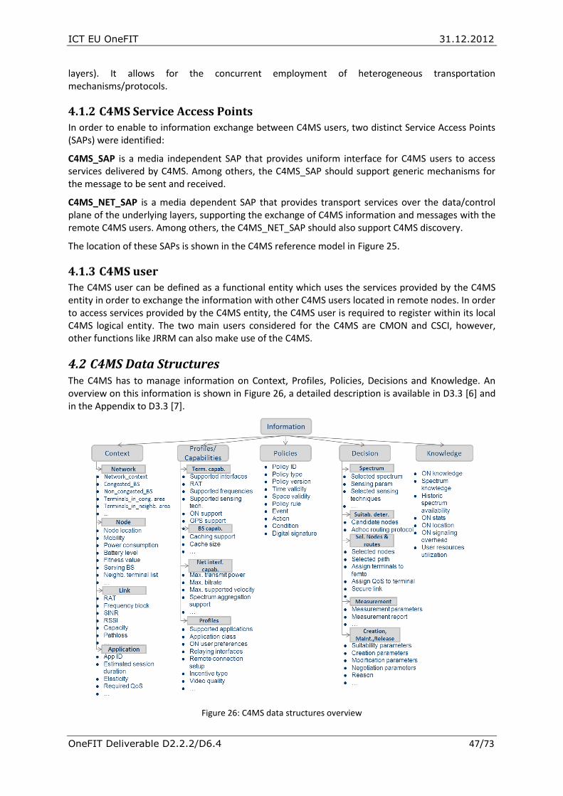
ICT EU OneFIT 31.12.2012
OneFIT Deliverable D2.2.2/D6.4 47/73
layers). It allows for the concurrent employment of heterogeneous transportation mechanisms/protocols.
4.1.2 C4MS Service Access Points In order to enable to information exchange between C4MS users, two distinct Service Access Points (SAPs) were identified:
C4MS_SAP is a media independent SAP that provides uniform interface for C4MS users to access services delivered by C4MS. Among others, the C4MS_SAP should support generic mechanisms for the message to be sent and received.
C4MS_NET_SAP is a media dependent SAP that provides transport services over the data/control plane of the underlying layers, supporting the exchange of C4MS information and messages with the remote C4MS users. Among others, the C4MS_NET_SAP should also support C4MS discovery.
The location of these SAPs is shown in the C4MS reference model in Figure 25.
4.1.3 C4MS user
The C4MS user can be defined as a functional entity which uses the services provided by the C4MS entity in order to exchange the information with other C4MS users located in remote nodes. In order to access services provided by the C4MS entity, the C4MS user is required to register within its local C4MS logical entity. The two main users considered for the C4MS are CMON and CSCI, however, other functions like JRRM can also make use of the C4MS.
4.2 C4MS Data Structures The C4MS has to manage information on Context, Profiles, Policies, Decisions and Knowledge. An overview on this information is shown in Figure 26, a detailed description is available in D3.3 [6] and in the Appendix to D3.3 [7].
Figure 26: C4MS data structures overview
Information
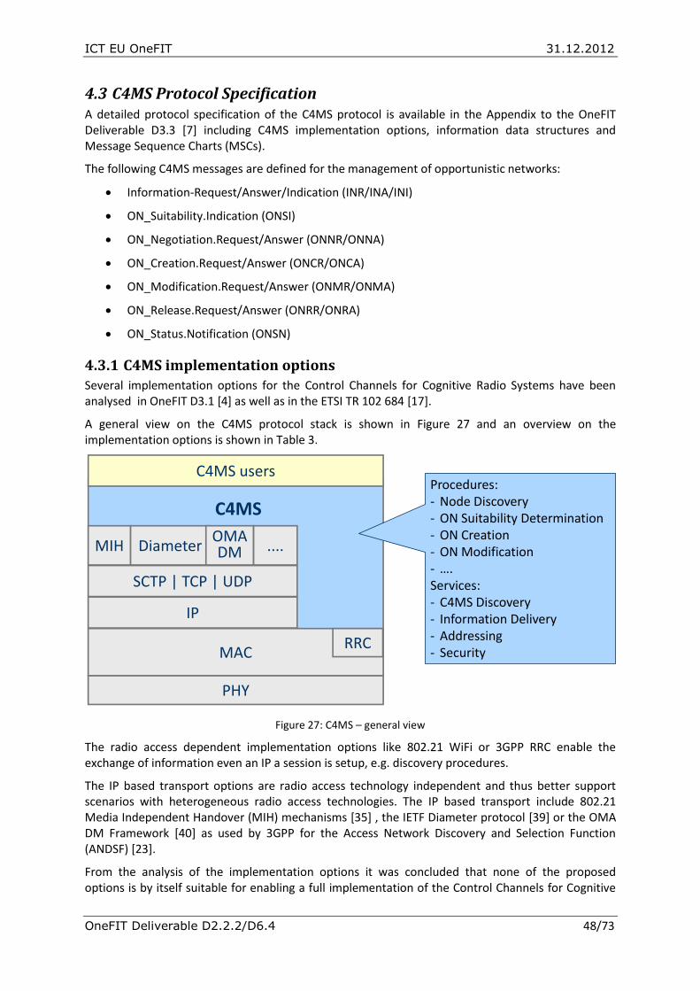
ICT EU OneFIT 31.12.2012
OneFIT Deliverable D2.2.2/D6.4 48/73
4.3 C4MS Protocol Specification A detailed protocol specification of the C4MS protocol is available in the Appendix to the OneFIT Deliverable D3.3 [7] including C4MS implementation options, information data structures and Message Sequence Charts (MSCs).
The following C4MS messages are defined for the management of opportunistic networks:
Information-Request/Answer/Indication (INR/INA/INI)
ON_Suitability.Indication (ONSI)
ON_Negotiation.Request/Answer (ONNR/ONNA)
ON_Creation.Request/Answer (ONCR/ONCA)
ON_Modification.Request/Answer (ONMR/ONMA)
ON_Release.Request/Answer (ONRR/ONRA)
ON_Status.Notification (ONSN)
4.3.1 C4MS implementation options
Several implementation options for the Control Channels for Cognitive Radio Systems have been analysed in OneFIT D3.1 [4] as well as in the ETSI TR 102 684 [17].
A general view on the C4MS protocol stack is shown in Figure 27 and an overview on the implementation options is shown in Table 3.
Figure 27: C4MS – general view
The radio access dependent implementation options like 802.21 WiFi or 3GPP RRC enable the exchange of information even an IP a session is setup, e.g. discovery procedures.
The IP based transport options are radio access technology independent and thus better support scenarios with heterogeneous radio access technologies. The IP based transport include 802.21 Media Independent Handover (MIH) mechanisms [35] , the IETF Diameter protocol [39] or the OMA DM Framework [40] as used by 3GPP for the Access Network Discovery and Selection Function (ANDSF) [23].
From the analysis of the implementation options it was concluded that none of the proposed options is by itself suitable for enabling a full implementation of the Control Channels for Cognitive
MACRRC
IP
SCTP | TCP | UDP
MIH DiameterOMA DM ....
C4MS users
C4MS
PHY
Procedures:- Node Discovery- ON Suitability Determination- ON Creation- ON Modification- ….Services:- C4MS Discovery- Information Delivery- Addressing- Security

ICT EU OneFIT 31.12.2012
OneFIT Deliverable D2.2.2/D6.4 49/73
Radio System. Thus, it is anticipated that the final C4MS implementation will be based on a combination of different radio independent and radio dependent solutions. Such a combination would eliminate the shortcomings identified in [17] and allow a full implementation of the C4MS supporting the exchange of information for between terminals, between terminals and the infrastructure as well as between infrastructure elements.
C4MS
protocol
option
Supported
Interfaces
Information
delivery
model
Basic
Connectivity
Required
Extension
of
baseline
standards
required
Protocols Addressing
Radio access independent
IEEE
802.21
MIH
T2N, N2N Unicast,
Multicast No Minor MIH
IP, L2 and
MIH
identifier
IETF
Diameter T2N, N2N Unicast Yes Minor DIAMETER IP
IETF
PAWS T2N Unicast
Towards
database None
e.g.
http/TLS String
3GPP
ANDSF T2N Unicast No Minor OMA-DM IP or E.164
Distributed
Agents
T2T, T2N,
N2N
Unicast,
Multicast Yes None CORBA/IIOP IP
TR069 N2N Unicast Yes Minor HTTP-SOAP IP
Radio access dependent
3GPP RRC
based T2N
Unicast,
Broadcast No Minor RRC
3GPP user
equipment
identifier
IEEE
802.11 T2T, T2N
Unicast,
Broadcast No Minor 802.11 L2
IEEE
802.11u T2N
Unicast,
Broadcast No None 802.11u L2
Direct WiFi T2T
(mainly)
Unicast,
Broadcast No Minor 802.11 L2
Bluetooth T2T
(mainly)
Unicast,
Broadcast No None
Bluetooth
2.1, 4.0 L2
WiMedia
UWB
T2T
(mainly)
Unicast,
Broadcast No None ECMA-368 L2
New Common Multi-RAT Control Layer Approaches
IEEE
802.19.1 T2N, N2N Unicast Yes None
To be
defined
To be
defined
Table 3: Control Channel implementation options [4][17]
In the OneFIT prototyping and validation activities, a C4MS based on an extended IEEE 802.21 protocol is used. Figure 28 shows as an example the “C4MS ON Creation Request Message” [12] from a coverage extension scenario. With this message, the infrastructure instructs a device to open an access point in order for being able to act as a relay. Further prototyping activities include other implementation options, e.g. by using Direct WiFi or by using distributed agents.

ICT EU OneFIT 31.12.2012
OneFIT Deliverable D2.2.2/D6.4 50/73
Figure 28: IEEE 802.21 based C4MS message example (C4MS ON Creation Request)[12]
** Transmitted: 127 Bytes over TCP/IP
10 00 34 72 *C4MS Header, MIH Message ID: C4MS_ON_Creation_REQ
00 0b 00 77 *C4MS Header, Payload Length: 119
01 06 *TLV Source_MIHF_Id NODE87
4e 4f 44 45
38 37
02 06 *TLV Dest_MIHF_Id NODE46
4e 4f 44 45
34 36
c0 01 *TLV ON_Id 7
07
c1 0b *TLV ON_Name AL_OppNet_1
41 4c 5f 4f
70 70 4e 65
74 5f 31
af 01 *TLV Reconfig.Type 2: Create Access Point (Relay)
02
f1 52 *TLV Type 241: Cell-Descriptor (Grouped), Length 82
a0 0b *TLV Access-Network-Id: AL_OppNet_1
41 4c 5f 4f
70 70 4e 65
74 5f 31
a1 08 *TLV Cell-Id
ff ff ff ff
ff ff ff ff
04 01 *TLV Link-Type
13
ad 01 *TLV Cell-Radius
64
b0 08 *TLV Freq-Used
80 24 f1 08
00 25 3f 28
b2 04 *TLV Configuration-Status
00 00 00 02
d0 23 *TLV Tech-Spec-Cell-Info
02 02 03 04
00 ff fe fd
fc 0c 22 4e
7f 20 40 b4
9e 0c 10 20
2c 41 6c 63
61 74 65 6c
2d 4c 75 63
65 6e 74
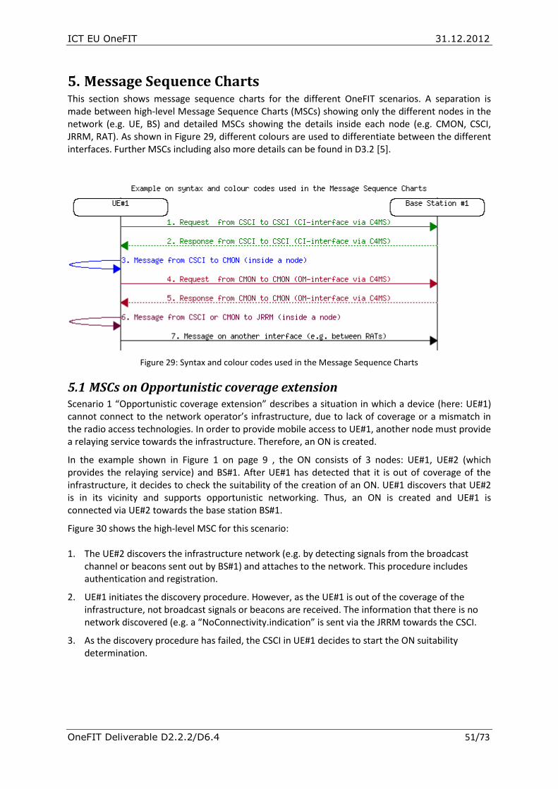
ICT EU OneFIT 31.12.2012
OneFIT Deliverable D2.2.2/D6.4 51/73
5. Message Sequence Charts This section shows message sequence charts for the different OneFIT scenarios. A separation is made between high-level Message Sequence Charts (MSCs) showing only the different nodes in the network (e.g. UE, BS) and detailed MSCs showing the details inside each node (e.g. CMON, CSCI, JRRM, RAT). As shown in Figure 29, different colours are used to differentiate between the different interfaces. Further MSCs including also more details can be found in D3.2 [5].
Figure 29: Syntax and colour codes used in the Message Sequence Charts
5.1 MSCs on Opportunistic coverage extension Scenario 1 “Opportunistic coverage extension” describes a situation in which a device (here: UE#1) cannot connect to the network operator’s infrastructure, due to lack of coverage or a mismatch in the radio access technologies. In order to provide mobile access to UE#1, another node must provide a relaying service towards the infrastructure. Therefore, an ON is created.
In the example shown in Figure 1 on page 9 , the ON consists of 3 nodes: UE#1, UE#2 (which provides the relaying service) and BS#1. After UE#1 has detected that it is out of coverage of the infrastructure, it decides to check the suitability of the creation of an ON. UE#1 discovers that UE#2 is in its vicinity and supports opportunistic networking. Thus, an ON is created and UE#1 is connected via UE#2 towards the base station BS#1.
Figure 30 shows the high-level MSC for this scenario: 1. The UE#2 discovers the infrastructure network (e.g. by detecting signals from the broadcast
channel or beacons sent out by BS#1) and attaches to the network. This procedure includes authentication and registration.
2. UE#1 initiates the discovery procedure. However, as the UE#1 is out of the coverage of the infrastructure, not broadcast signals or beacons are received. The information that there is no network discovered (e.g. a “NoConnectivity.indication” is sent via the JRRM towards the CSCI.
3. As the discovery procedure has failed, the CSCI in UE#1 decides to start the ON suitability determination.
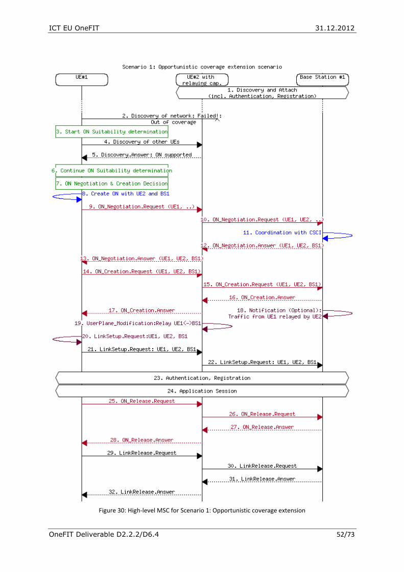
ICT EU OneFIT 31.12.2012
OneFIT Deliverable D2.2.2/D6.4 52/73
Figure 30: High-level MSC for Scenario 1: Opportunistic coverage extension

ICT EU OneFIT 31.12.2012
OneFIT Deliverable D2.2.2/D6.4 53/73
4. The UE#1 initiates a discovery procedure towards other terminals. This may e.g. be done by
sending probe requests or by listening to beacons from other devices.
5. The UE#2 sends an answer to the discover request indicating that it supports ONs. Instead of an answer like answering a probe request, this could also be another message like a beacon or a broadcast message.
6. The CSCI in UE#1 continues the ON suitability determination.
7. After the CSCI in UE#1 has decided that an ON may be suitable, a decision is made that an ON shall be created.
8. The CSCI triggers the CMON in UE#1 to start the negotiation and creation of an ON. This message includes information that UE#2 shall be part of the ON.
9. An ON_Negotiation.Request including the capabilities and requirements from UE#1 is sent from UE#1 to UE#2 via C4MS.
10. UE#2 adds its own context information to the ON_Negotiation.Request and sends this message to BS#1.
11. Inside BS#1, the CMON coordinates with the CSCI in order to provide additional information from the infrastructure to the negotiation procedure. This procedure may additionally include interactions with the DSM in order to find appropriate frequencies for the ON (The interactions with the DSM are not shown in the diagram).
12. The BS#1 evaluates the ON_Negotiation.Request and sends an ON_Negotiation.Answer including a list of nodes (UE#1, UE#2 and BS#1) which should form the ON.
13. The ON_Negotiation.Answer is forwarded by UE#2 to UE#1. From the negotiation procedure, the UE#1 has now all relevant information from the involved nodes.
14. The ON_Creation.Request is sent via C4MS from the CMON in UE#1 to the CMON in UE#2.
15. The ON_Creation.Request is forwarded to BS#1.
16. The BS#1 sends an ON_Creation.Answer indicating that it is now included in the ON.
17. The UE#2 forwards the ON_Creation.Answer with an additional indication that UE#2 is now also part of the ON to UE#1.
18. If needed, the transceiver in BS#1 is configured to be able to receive traffic from UE#1 via UE#2.
19. UE#2 configures its transceiver so that traffic from UE#1 can be forwarded/relayed to BS#1 and vice versa.
20. The CMON in UE#1 initiates the setup of the user plane related radio link via the JRRM towards the underlying RAT.
21. A RAT-specific LinkSetup.Request is sent towards UE#2. In UMTS or LTE for example, this message may be a RRC Connection.Request.
22. A radio link setup or a modification of the existing link is also initiated between UE#2 and BS#1.
23. RAT-specific Authentication and Registration procedures are now being executed.
24. The Application Session is now active. At this point, radio link configurations between UE#1 and UE#2 and UE#2 and BS#1 can be modified (i.e., ON reconfiguration procedure) attending to the characteristics of the application/session being supported.
25. When the application session has ended, the CMON determines that the ON is no longer needed and an ON_Release.Request is sent from UE#1 to UE#2.

ICT EU OneFIT 31.12.2012
OneFIT Deliverable D2.2.2/D6.4 54/73
26. UE#2 forwards the ON_Release.Request to BS#1
27. BS#1 answers that the ON can be released.
28. UE#2 forwards the ON_Release.Answer to BS#1.
29. The CMON in UE#1 sends a LinkRelease.Request via JRRM towards the underlying RAT and a RAT-specific LinkRelease.Request (e.g. RRC Connection Release in UMTS) is sent to UE#2-
30. The RAT-specific LinkRelease.Request is forwarded to BS#1.
31. The BS#1 releases all resources and sends a RAT-specific LinkRelease.Answer to UE#2
32. The UE#2 releases all resources and sends a RAT-specific LinkRelease.Answer to UE#1. The UE#1 then also releases all its resources and informs the CMON. The ON is then released.
5.2 MSC on “Opportunistic capacity extension” Scenario 2 “Opportunistic capacity extension” depicts a situation in which a part of the network (e.g. BS#1 in Figure 2 on page 10) is highly loaded. Therefore, only limited service can be provided to a user at the cell edge (e.g. UE#1). As other parts of the network are less loaded (BS#2), the solution is to create an ON consisting of UE#1, UE#2 and BS#2. In that ON, UE#2 provides a relaying service between UE#1 and BS#2 and thus satisfactory QoS can be provided to UE#1.
The MSC for this scenario is shown in Figure 31. There, UE#1 is first attached to the base station BS#1 while UE#2 is attached to BS#2. UE#1 established an application session but due to the fact that BS#1 in this example is highly congested, the provided QoS is insufficient. In order to improve the QoS, the UE#1 decides to check if an ON can be created. Alternatively, as the network (BS#1) is also aware of the insufficient QoS, the network may also trigger the check if an ON shall be created.
UE#1 discovers that UE#2 is in its vicinity and supports opportunistic networking, thus an ON is created between UE#1 and UE#2. After handover execution, the traffic from UE#1 is then relayed via UE#2 towards base station BS#2.
Description of the Messages used in Figure 31:
1. At the beginning of the scenario, the BS#1 is already in high load because BS#1 serves already several other users which are not shown in the MSC.
2. The BS#1 informs regularly its surrounding Base Stations, e.g. BS#2 about its load situation.
3. The UE#1 discovers and attaches to the network (via BS#1). This procedure includes authentication and registration.
4. The UE#2 discovers and attaches to the network (via BS#2). This procedure includes authentication and registration.
5. In the infrastructure network, cell load indications are regularly exchanged. Here, BS#2 informs BS#1 that it is in a low load situation.
6. UE#1 starts an application session.
7. Due to the high load in the cell of BS#1, the UE#1 experiences bad performance. A measurement report is sent to BS#1 indicating the low QoS.

ICT EU OneFIT 31.12.2012
OneFIT Deliverable D2.2.2/D6.4 55/73
Figure 31: High-level MSC for Scenario 2: Opportunistic capacity extension

ICT EU OneFIT 31.12.2012
OneFIT Deliverable D2.2.2/D6.4 56/73
8./9. Two options are possible on which node reacts first to improve the bad performance situation:
8./9. The UE#1 may decide to check if an ON can be created. Alternatively, the BS#1, which has more context information about the network, e.g. that BS#2 is suitable due to its low load, can also trigger the creation of the ON.
10. In Alternative 2, the BS#1 sends an ON_Suitability.Indication to UE#1 indicating that BS#2 has been identified as a candidate for the creation of a new ON.
11. As UE#1 is out of coverage of BS#2, it has to discover other network elements or UEs which can be part of the ON.
12. UE#2 provides information that it is supporting ONs. This can either be a dedicated message or some broadcasted information.
13. The CSCI in UE#1 decides that the ON shall now be created.
14. The CSCI triggers the CMON in UE#1 to start the creation of an ON including UE#1, UE#2 and BS#2.
15. An ON_Negotiation.Request including the capabilities and requirements from UE#1 is sent from UE#1 to UE#2.
16. UE#2 adds its own context information to the ON_Negotiation.Request and sends this message to BS#2. At this point, the CMON in BS#2 may coordinate with the CSCI in BS#2 in order to provide additional information from the infrastructure to the negotiation procedure.
17. The BS#2 evaluates the ON_Negotiation.Request and sends an ON_Negotiation.Answer including a list of nodes (UE#1, UE#2 and BS#2) which should form the ON.
18. The ON_Negotiation.Answer is forwarded by UE#2 to UE#1.
19. The ON_Creation.Request is sent via C4MS from the CMON in UE#1 to the CMON in UE#2.
20. The ON_Creation.Request is forwarded to BS#2.
21. The BS#2 sends an ON_Creation.Answer indicating that it is now included in the ON.
22. The UE#2 forwards the ON_Creation.Answer with an additional indication that UE#2 is now also part of the ON to UE#1.
23. If needed, the transceiver in BS#2 is configured to be able to receive traffic from UE#1 via UE#2.
24. UE#2 configures its transceiver so that traffic from UE#1 can be forwarded/relayed to BS#2 and vice versa.
25. The CMON in UE#1 initiates the setup of the radio link for the user plane (or modification of an existing radio link) via the JRRM towards the underlying RAT.
26. A RAT-specific LinkSetup.Request is sent towards UE#2. In UMTS or LTE for example, this message may be a RRC Connection.Request.
27. A radio link setup or modification of the existing one is also initiated between UE#2 and BS#1
28. RAT-specific Session Handover procedures are now being executed.
29. After the handover, the session is continued with improved QoS.
30. After the end of the session, a release procedure is executed. This procedure is similar to the detailed release procedure described in the previous scenario described in section 5.2.

ICT EU OneFIT 31.12.2012
OneFIT Deliverable D2.2.2/D6.4 57/73
5.3 MSCs on Infrastructure supported opportunistic device-to-device networking
Scenario 3 “Infrastructure supported opportunistic device-to-device networking” shows the creation of an infrastructureless opportunistic network between two or more devices for the local exchange of information (e.g. peer-to-peer communications, home networking, location-based service providing, etc.).
A differentiation can be made if the detection of the opportunity is inside the infrastructure as shown in section 5.3.1 below or if the decision for the need of the D2D connection is made inside the user terminal as shown in section 5.3.2.
5.3.1 Infrastructure initiated opportunistic device-to-device networking
Figure 32 shows an example scenario where the network detects the suitability of a D2D connection based on traffic rerouting in the Public Data Gateway and then sets up a D2D connection.
Figure 32: Setup of D2D connection based on the detection of data rerouting in the PDN Gateway
In this example, UE#1 starts a data session. The session setup message typically indicates that a data session to a PDN (Public data network) shall be established but does not include any hints that a D2D session may be useful. Now UE#1 starts exchanging data. In this example, most of the data is exchanged with UE#2. The network (e.g. the PDN-Gateway) detects that most of the traffic from
Base Station(NodeB, eNB,
HeNB)
Serving Gateway
(SGW)
Public Data Network
Gateway (PDN GW, GGSN)
Mobility Management Entity (MME)
Control PlaneUser Plane (Routed via network, before D2D connection is setup)User Plane (D2D connection)
UE#1
UE#2
I. UE#1 sets up a normal data session
II. UE#1 starts transmitting data towards UE#2
III. Data is routed through the gateway back to the RAN to UE#2This routing back is an indicator that routing can be optimised and – in case of proximity of UE#1 with UE#2 – a D2D session may be setup
IV. Gateway notifies CSCI in the Core Network (typically via SGW) that D2D may be possible
V. MME (after performing suitability determination) sets up a D2D connection for the user plane between UE#1 and UE#2
V. CSCI in MME (after performing suitability determination) sets up a D2D connection for the user plane between UE#1 and UE#2
CMON
CMON
ON Manager
CSCI

ICT EU OneFIT 31.12.2012
OneFIT Deliverable D2.2.2/D6.4 58/73
UE#1 is routed back via the same BS or a neighbouring BS towards UE#2. The network performs some further checks on the capabilities of UE#1 and UE#2 and the subscriptions and makes an initial estimation if a D2D connection may be suitable and thus, the traffic can be offloaded from the network by creating an opportunistic network between UE#1 and UE#2. Therefore, BS#1 triggers UE#1 with the ON_Suitability.Indication to check if an ON between UE#1 and UE#2 can be established.
An MSC for this example is shown in in Figure 33. The following messages are used:
1. The UE#1 discovers and registers to the network. This procedure includes authentication.
2. The UE#2 discovers and registers to the network. This procedure includes authentication.
3. UE#1 starts a data session. The SessionSetup.request is sent via RAT-specific signalling towards the infrastructure network. This message can e.g. be a UE triggered Service Request as described in 3GPP 23.401 Section 5.3.4.1.
4. UE#1 starts sending uplink data and the data packets are addressed for UE#2.
5. The network detects that destination of the packets (UE#2) is in the same network
6. The network sends a SessionSetup.request to UE2. This message can e.g. be a Network triggered Service Request as described in 3GPP 23.401 Section 5.3.4.3.
7. The data from UE#1 is sent via the downlink to UE#2.
Based on network internal information (e.g. both UE#1 and UE#2 are registered to the same BS, both UEs support D2D communication), the network decides that a direct link between UE#1 and UE#2 may be possible and thus it is proposed to create an ON.
8. The CSCI in the network sends an ON_Suitability.Indication towards UE#1 indicating that an ON with UE#1 and UE#2 may be possible.
9. UE#1 starts a discovery procedure, e.g. probing if UE#2 is in its vicinity or by listening on broadcast/beacon information from UE#2.
10. Discovery information is received from UE#2 indicating that it is supporting ONs.
11. The CSCI in UE#1 decides that the ON shall now be created. The goal of the ON is to have a direct device-to-device link between UE#1 and UE#2.
12. The CSCI triggers the CMON in UE#1 to start the creation of ON including UE#1 and UE#2.
13. An ON_Negotiation.Request including the capabilities and requirements from UE#1 is sent from UE#1 to UE#2.
14. UE#2 positively answers the negotiation and provides further context information from UE#2.
15. The CMON informs the CSCI that the negotiation was successful.
16. UE#1 provides an ON_Negotiation.Indication to the BS indicating the successful negotiation of the ON. This means that there is no need to have the BS involved in the session requested in message nbr. 3.
17. The BS answers the SessionSetup.request from Msg. #3 with a SessionSetup.response that the session via the network is rejected and instead a direct link using the ON shall be used.

ICT EU OneFIT 31.12.2012
OneFIT Deliverable D2.2.2/D6.4 59/73
Figure 33: High-level MSC for Scenario 3.1: Infrastructure initiated opportunistic D2D networking
18. The ON_Creation.Request is sent via C4MS from the CMON in UE#1 to the CMON in UE#2.

ICT EU OneFIT 31.12.2012
OneFIT Deliverable D2.2.2/D6.4 60/73
19. The UE#2 replies with an ON_Creation.Answer.
20. The CMON in UE#1 initiates the setup of the user plane radio link via the JRRM towards the underlying RAT.
21. Authentication procedures between terminals may be executed at this point.
22. A RAT-specific LinkSetup.Request is sent towards UE#2. In UMTS or LTE for example, this message may be a RRC Connection.Request.
23. The BS is notified by UE#1 that the ON has been successfully established.
24. UE#2 also notifies the network that the ON has been successfully established.
25. The Application Session is now active.
26. After the end of the Application Session, the ON is no longer needed and an ON_Release.request is sent to UE#2.
27. UE#2 confirms the release of the ON in the ON_Release.answer.
28. The user plane link is released with a RAT-specific LinkRelease.Request
29. UE#2 confirms the release of the link.
30. UE#1 notifies the network that the ON no longer exists.
31. UE#2 also notifies the network that the ON no longer exists.
5.3.2 Terminal initiated opportunistic device-to-device networking In this scenario, the user’s application wants to establish a D2D connection, e.g. for a localised service. This service wants to exchange information with another user in the area, thus the opportunistic management is triggered to create the D2D connection. As shown in Figure 34, the device sends already an indication that a D2D session is needed in the session setup request to the network. The network then guides the setup of the D2D session.

ICT EU OneFIT 31.12.2012
OneFIT Deliverable D2.2.2/D6.4 61/73
Figure 34: The UE sends a request for a D2D connection to the network, which guides the setup of the D2D connection
Figure 35 shows the MSC for this scenario. The following messages are used:
1. The UE#1 discovers the network and attaches to it. This procedure includes authentication and registration.
2. An application in UE#1 wants to connect to other users in the area, e.g. to provide local services. Therefore, an ON shall be created. The CSCI is triggered to start the ON suitability determination.
3. The UE#1 sends a SessionSetup.Request via RAT-specific signalling towards the infrastructure network. In difference to the previous scenario where e.g. a standard UE triggered Service Request as described in 3GPP 23.401 Section 5.3.4.1 is used, this message contains one or more parameters indicating that a Device-to-Device connection is requested and an identifier of UE#2.
Alternatively, the UE#1 may send an Information .Request indication which information is needed, e.g. requesting information on which spectrum to use and which policies to consider.
4. The infrastructure replies with a SessionSetup.Answer message including policies, information on how UE#2 may be discovered and which spectrum to use.
In the alternative where an Information.Request has been sent to the infrastructure, the infrastructure sends an Information.Answer including the requested information.
5. The UE#1 starts a discovery procedure to discover other terminals in the area.
Base Station(NodeB, eNB,
HeNB)
Serving Gateway
(SGW)
Public Data Network
Gateway (PDN GW, GGSN)
Mobility Management Entity (MME)
Control PlaneUser Plane
UE#1
UE#2
1. UE#1 sends a session setup request to network indicating that a D2D session towards UE#2 shall be setup
2. Network sets up a direct D2D connection between UE#1 and UE#2
2. Network sets up a direct D2D connection between UE#1 and UE#2
3. Direct user plane connection is setup between UE#1 and UE#2
CMON
CMON
ON Management
CSCI

ICT EU OneFIT 31.12.2012
OneFIT Deliverable D2.2.2/D6.4 62/73
Figure 35: High-level MSC for Scenario 3.2: Terminal initiated opportunistic device-to-device networking

ICT EU OneFIT 31.12.2012
OneFIT Deliverable D2.2.2/D6.4 63/73
6. Discovery information is received from UE#2 indicating that it is supporting ONs. This procedure may include already an RAT-specific associate/join in order to exchange further messages.
7. The CSCI in UE#1 finalises the suitability determination with the decision that the ON shall now be created. The goal of the ON is to have a direct device-to-device link between UE#1 and UE#2.
8. The CSCI triggers the CMON in UE#1 to start the creation of the ON including UE#1 and UE#2.
9. An ON_Negotiation.Request including the capabilities and requirements from UE#1 is sent from UE#1 to UE#2.
10. UE#2 positively answers the negotiation and provides further context information from UE#2.
11. The ON_Creation.Request is sent via C4MS from the CMON in UE#1 to the CMON in UE#2.
12. The UE#2 replies with an ON_Creation.Answer.
13. So far, only Control-Plane signalling took place between the UEs. For some RATs, e.g. UMTS/LTE, a separate link is needed for the exchange of User-Plane signalling. For the creation of such a user-plane link, a LinkSetup.Request is sent from the CMON to the JRRM which forwards it to the underlying RAT.
14. Authentication procedures are executed.
15. A RAT-specific LinkSetup.Request is sent towards UE#2. In UMTS or LTE for example, this message may be a RRC Connection.Request. In other technologies where the same link can be used for control- and user-plan signalling, e.g. WLAN, this may not be necessary.
Inside UE#1, the CSCI is notified by the CMON that the ON has been successfully established.
16. UE#1 notifies the network that the ON has been successfully established.
17. In the case that UE#2 has a link to the network, the UE#2 also notifies the network that the ON has been successfully established.
18. The Application Session is now active.
19. After the end of the Application Session, the ON is no longer needed and an ON_Release.request is sent to UE#2.
20. UE#2 confirms the release of the ON in the ON_Release.answer.
21. The user plane link is released with a RAT-specific LinkRelease.Request
22. UE#2 confirms the release of the link.
23. Inside UE#1, the CMON informs the CSCI that the ON has been released. UE#1 then notifies the network that the ON no longer exists.
24. In the case that UE#2 has a link to the network, UE#2 notifies the network that the ON no longer exists.

ICT EU OneFIT 31.12.2012
OneFIT Deliverable D2.2.2/D6.4 64/73
5.4 MSC on opportunistic traffic aggregation in the radio access network
Scenario 4 “Opportunistic traffic aggregation in the radio access network” describes the usage of a local opportunistic network among several devices, in order to share a reduced number of infrastructure links towards a remote service-providing server or database. This situation as shown in Figure 4 on page 11allows some degree of traffic aggregation and caching that is useful to improve the overall network performance.
UE#1 and UE#2 are attached to BS#1 to access some remote services. BS#1 discovers that UE#1 supports lower maximal bit rate than itself (alternatively, UE#1 detects that BS#1 supports higher maximal bit rate than itself) and requests UE#1 to start discovery procedures to provide it with some local context information. UE#1 discovers that UE#2 is in its vicinity and reports it to BS#1. BS#1 determines that UE#2 supports higher maximal bit rate and requests UE#1 to create an ON with UE#2. UE#1 and UE#2 establish the ON thus enabling UE#1 to be connected via UE#2 towards the base station BS#1.
Description of the Messages used in Figure 36: 1. The UE#2 discovers and registers to the network. This procedure includes authentication.
2. The UE#1 discovers and registers to the network. This procedure includes authentication.
3. The UE#1 starts an Application Session using a direct link to BS#1.
4. The BS#1 detects the limited UE#1 capabilities (e.g. UE#1 does not support higher order modulation or MIMO, supported by BS#1) and starts the ON Suitability determination.
5. The BS sends an ON_Discovery.Request to UE#1 to trigger discovery procedures in UE#1. As the discovery procedure may include a reconfiguration of the transceiver, such a reconfiguration is made via the messages 5.1, 5.2, 5.3. and 5.4.
6. UE#1 initiates the discovery of other UEs in its vicinity.
7. UE#2 provides discovery information indicating that opportunistic networking is supported.
8. UE#1 answers the previous ON_Discovery.Request with an ON_Discovery.Answer towards BS#1 indicating that UE#2 is a candidate for the ON.
9. The CSCI in BS#1 continues the ON suitability determination and decides that an ON shall be created. The CSCI in the BS#1 decides that an ON will be created. The goal of the ON is to aggregate traffic from UE#1 in the existing link between UE#2 and the BS#1. In order to do so, UE#1 must setup the link towards UE#2.
10. The CSCI in BS#1 triggers the CMON to create an ON consisting of UE#1, UE#2 and BS#1.
11. BS#1 negotiates with UE#2 if UE#2 can be part of the ON.
12. UE#2 answers the ON_Negotiation indicating that it is willing to participate in the ON.
13. BS#1 negotiates with UE#1 indicating that UE#2 has agreed to be part of the ON.
14. UE#1 positively answers the ON_Negotiation.
15. The ON_Creation.Request is sent to UE#2
16. UE#2 replies with an ON_Creation.Answer.
17. The ON_Creation.Request is sent to UE#2

ICT EU OneFIT 31.12.2012
OneFIT Deliverable D2.2.2/D6.4 65/73
Figure 36: High-level MSC for Scenario 4: Opportunistic traffic aggregation in the radio access network

ICT EU OneFIT 31.12.2012
OneFIT Deliverable D2.2.2/D6.4 66/73
18. UE#2 replies with an ON_Creation.Answer.
19. Inside the BS, necessary User Plane / Transceiver modifications are performed (BS#1 is pre-configured to be able to receive/ transmit traffic from/to UE#1 via UE#2)."
20. Inside UE#2, the necessary User Plane / Transceiver modifications are also performed (UE#2 pre-configures its transceiver so that traffic from UE#1 can be forwarded/relayed to BS#1 and vice versa).
21. Inside UE#1, the CMON triggers the RAT-specific LinkSetup
22. UE#1 sends a LinkSetup.Request to UE2.
23. The LinkSetup.Request is forwarded to BS#1
24. A Handover of the session from the direct link between UE#1 and the BS#1 is made so that UE#1 now uses a link towards UE#2 which aggregates the traffic towards BS#1.
25. The Application Session continues now via the aggregated link.
26. – 32.: After the Application session has been terminated, the ON is no longer needed and the ON is released.
5.5 MSC on opportunistic resource aggregation in the backhaul network Scenario 5 “Opportunistic resource aggregation in the backhaul network” depicts how opportunistic networks can be used to aggregate both backhaul bandwidth and processing/storage resources on access nodes. In this case, the ON is created over access points rather than user terminals, thus offering a new focus on system performance improvement.
One of the use cases for the backhaul resource aggregation is depicted in Figure 18. In this example base station 2 has problem with its backhaul link (it is congested or broken) and forms an ON with the neighbouring base stations in order to use their backhaul links to offload traffic from its congested backhaul link.
Figure 37 shows the high level MSC for the scenario example from the Figure 5 on page 11. Base stations are fixed network nodes and every one of them can store data about the neighbouring base stations that it can establish links with, so there is no need for the discovery procedure. In this example, when the BS2 detects problem with its backhaul link it can immediately start the ON suitability determination procedure and start the ON negotiation with its neighbouring BSs. BS2 asks its neighbouring BSs for status and capabilities of their backhaul links and decides to create an ON with BS1 and BS3. Routing tables of the base stations that are participating in ON are updated. When the spare capacity of the BS3 backhaul link decreases below some threshold, or the backhaul traffic intensity for BS2 decreases (depicted in Figure 37), BS3 can leave the ON, which continues to exist between BS2 and BS1 while needed.
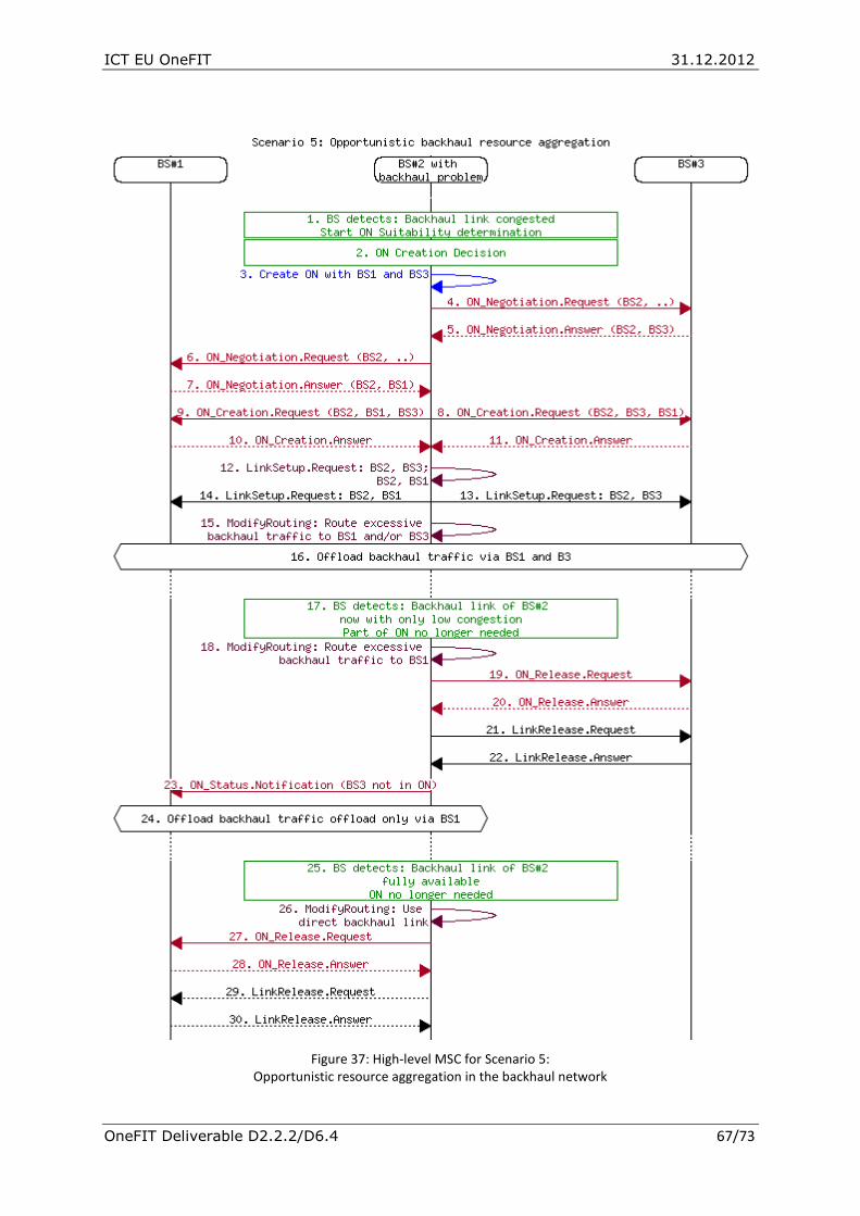
ICT EU OneFIT 31.12.2012
OneFIT Deliverable D2.2.2/D6.4 67/73
Figure 37: High-level MSC for Scenario 5: Opportunistic resource aggregation in the backhaul network

ICT EU OneFIT 31.12.2012
OneFIT Deliverable D2.2.2/D6.4 68/73
Description of the Messages used in Figure 37: 1. The BS#2 detects that the backhaul link is congested or broken. Thus, BS#2 starts the ON
Suitability determination towards its neighbouring bases stations which are BS#1 and BS#3.
2. BS#2 decides to create an ON with BS#1 and BS#3.
3. Inside BS#2, the CSCI triggers the CMON to create the ON.
4. An ON_Negotiation.Request indicating that BS#2 wants to use BS#3 to backhaul it’s traffic is sent to BS#3.
5. BS#3 positively replies with an ON_Negotiation.Answer.
6. A similar ON_Negotiation.Request indicating that BS#2 wants to use BS#1 to backhaul it’s traffic is sent to BS#1.
7. BS#1 positively replies with an ON_Negotiation.Answer.
8. and 9.: BS#2 sends an ON_Creation.Request to BS#1 as well as to BS#3.
10. and 11.: Both BS#1 and BS#3 are replying with an ON_Creation.Answer.
12. Inside BS#2, CMON instructs JRRM to setup links towards BS#1 and BS#3
13. and 14.: LinkSetup.Requests are sent to BS#1 and BS#3.
15. Inside the BS#2, the routing is changed so that all backhaul traffic which can not be transported via the direct link is routed towards BS#1 and/or BS#3 (loadsharing).
16. The backhaul traffic is offloaded via BS#1 as well as BS#3.
17. The direct backhaul link is partially available again, thus a part of the ON can be released.
18. The routing is modified so that there will be no backhaul traffic towards BS#3.
19.-22.: BS#3 will be removed from the ON and the Link to BS#3 is released.
23. BS#1 is notified that BS#3 is no longer part of the ON.
24. Part of the traffic is still offloaded via BS#1.
25. The direct backhaul of BS#2 is now available with full capacity (no congestion), thus the ON is no longer needed.
26. The routing is modified so that there will be no backhaul traffic towards BS#3.
27.-30.: When the ON is no longer needed, the ON and the related links are released.

ICT EU OneFIT 31.12.2012
OneFIT Deliverable D2.2.2/D6.4 69/73
6. Algorithms for enabling opportunistic networks The intention of this section is to give the reader an overview where further information on the OneFIT algorithms can be found but not to describe the algorithms themselves.
The OneFIT algorithms are described in detail in D4.1 [9] and performance assessments are given in D4.2 [10] and D4.3 [11].
The algorithms for the management of opportunistic networks can be grouped according the main phases in the operation of an ON. As shown in Figure 38, the main phases are suitability determination, ON creation, ON maintenance and ON termination.
Figure 38: Main phases in the operation of an ON and the related key functionalities
The following algorithms are described in D4.1 [9]:
Algorithms for suitability determination: 1. Discovery of terminals supporting opportunistic networks
2. Spectrum opportunity identification and selection
3. Machine learning based knowledge acquisition on spectrum usage
4. Techniques for aggregation of available spectrum bands/fragments
5. Knowledge based suitability determination
6. UE to UE Trusted direct path Algorithms for ON Creation:
7. Selection of nodes and routes
SUITABILITY CREATION MAINTENANCE
TERMINATION
•Detection of opportunities •Nodes• Applications• Mobility
• Resources
• Potential radio paths
•Assessment of potential gains
ON creation for:• Coverage
extension• Capacity
extension• Localized service
provision
• Traffic aggregation in the RAN
• Resource aggregation in the backhaul network
• Input to the creation phase is the information and knowledge accumulated from the suitability phase
Monitor• Nodes
• Spectrum• Policies• QoS
Reconfiguration:•Modification of an ON•Merge/Split ONs (governed by the operator)
•Alterations to the nodes, spectrum, operator’s policies, QoS trigger the maintenance phase
• Cessation of application provision• Resource release
• Inadequate gains• Handover to
infrastructure• Resource release
•Forced termination• Handover to
infrastructure for preserving important flows
• Resource release
Composite Wireless NetworkOpportunistic Network
• Suitability triggers the creation phase
SECURITY & TRUST

ICT EU OneFIT 31.12.2012
OneFIT Deliverable D2.2.2/D6.4 70/73
8. Route pattern selection in ad hoc network
9. QoS and Spectrum aware routing techniques
10. Application cognitive multipath routing in wireless network Algorithms for ON Maintenance:
11. Multi-flow routes co-determination
12. Techniques for network reconfiguration - topology design
13. Content conditioning and distributed storage virtualization/aggregation for context driven media delivery
Further on, the OneFIT algorithms have been validated in different prototypes and demonstrators as described in D5.2 [12] and D5.3 [13]. The validation platform architecture, which shows the different types of nodes in these proof-of-concepts activities and a mapping of the OneFIT building blocks to these nodes, is shown in Figure 39 below.
Figure 39: OneFIT validation platform architecture
ON-enabled
Mobile Devices
Public mobile network
& Internet
Femto AP
Infrastructure
(also mimicking
macro AP)
WiFi AP
Infrastructure
User Data
Flow
C4MS
Flow
3G
RAT
CMON & CSCI
JRRM, CCM
CMON & CSCIDSM, DSONPM
WiFi
RAT
WiFi
RAT
3G
RAT
ON Manager
xxxTransport
Techno
Building
Block
3G
ADSL
ADSL
WiFi 3G
WiFi
Device-to-device
Application
JRRM, CCM
3G
RAT
CMON & CSCI
WiFi
RAT
Device-to-device
Application
JRRM, CCM
LAN

ICT EU OneFIT 31.12.2012
OneFIT Deliverable D2.2.2/D6.4 71/73
7. Conclusions The OneFIT project has carried out a wide range of research on operator governed opportunistic networking covering architecture, control channel design, algorithms and validation on hardware platforms.
This document has presented the OneFIT functional and system architecture for the management and control of infrastructure coordinated opportunistic networks (ONs).
The two main building blocks for the ON management are:
the CSCI (Cognitive management System for the Coordination of the infrastructure) which is responsible for the detection of situations where an ON is useful, decides on the suitability of an ON and provides policy and context information from the infrastructure to the ON;
The CMON (Cognitive Management system for the Opportunistic Network) which then creates and maintains an ON based on the directives from the CSCI.
In the System Architecture, three options have been presented for the mapping of the OneFIT elements to network entities and the Security Architecture including different security mechanisms.
Further on, Message Sequence Charts (MSCs) are described for the five main OneFIT scenarios:
Opportunistic Coverage Extension
Opportunistic Capacity Extension
Infrastructure supported opportunistic device-to-device networking
Opportunistic traffic aggregation in the radio access network
Opportunistic resource aggregation in the backhaul network
This OneFIT architecture described in this document has provided a basis for the work in the other workpackages:
Design and specification of the “Control Channels for the Cooperation of the Cognitive Management Systems” (C4MS) in WP3 [4][5][6][8]
Algorithms for enabling opportunistic networks in WP4 [10][11]
Integration of the OneFIT functions into an experimental platform where the OneFIT concepts will be validated [12][13].
Furthermore, as described in [14], the major features developed during the project have been actively promoted to standardization and regulation forums to allow the introduction of opportunistic networks with cognitive management systems.

ICT EU OneFIT 31.12.2012
OneFIT Deliverable D2.2.2/D6.4 72/73
8. References [1] ICT-2009-257385 OneFIT Project, http://www.ict-onefit.eu/
[2] OneFIT Deliverable D2.1 “Business scenarios, technical challenges and system requirements”, October 2010
[3] OneFIT Deliverable D2.2 “OneFIT functional and system architecture”, Febr. 2011
[4] OneFIT Deliverable D3.1 “Proposal of C4MS and inherent technical challenges”, March 2011
[5] OneFIT Deliverable D3.2 ”Information definition and signalling flows”, Sept. 2011
[6] OneFIT Deliverable D3.3 “Protocols, performance assessment and consolidation on interfaces for standardization”, June 2012
[7] Appendix to OneFIT Deliverable D3.3: “Detailed C4MS Protocol Specification”, June 2012
[8] OneFIT Deliverable D3.4 “Report on C4MS Standardisaton”, Dec. 2012
[9] OneFIT Deliverable D4.1 “Formulation, implementation considerations, and first performance evaluation of algorithmic solutions”, June 2011
[10] OneFIT Deliverable D4.2 “Performance assessment & synergic operation of algorithmic solutions enabling opportunistic networks”, June 2012
[11] OneFIT Deliverable D4.3 “Performance Evaluation of synergic operation of algorithms enabling opportunistic networks”, Dec. 2012
[12] OneFIT Deliverable D5.2 “Validation platform implementation”, July 2012
[13] OneFIT Deliverable D5.3 “Results analysis and validation”, Dec. 2012
[14] OneFIT Deliverable D6.3 “Final Report on Dissemination, Regulation, Standardization, Exploitation & Training”, Dec. 2012
[15] ETSI TR 102 682 “Functional Architecture for the Management and Control of Reconfigurable Radio Systems”, July 2009
[16] ETSI TR 102 683 “Cognitive Pilot Channel”, Sept. 2009
[17] ETSI TR 102 684 „Feasibility Study on Control Channels for Cognitive Radio Systems“, April 2012
[18] 3GPP TS 21.133 “3G security; Security threats and requirements”
[19] 3GPP TR 22.803 “Feasibility Study for Proximity Services (ProSe) (Rel12)”
[20] 3GPP TS 23.203 “Policy and charging control architecture”
[21] 3GPP TS 23.234 “3GPP system to Wireless Local Area Network (WLAN) interworking; System description”
[22] 3GPP TS 23.401 “GPRS enhancements for E-UTRAN access”
[23] 3GPP TS 23.402 “Architecture enhancements for non-3GPP accesses”
[24] 3GPP TS 24.302 “Access to the 3GPP Evolved Packet Core (EPC) via non-3GPP access networks”
[25] 3GPP TS 25.331 “Radio Resource Control (RRC); Protocol Specification”
[26] 3GPP TS 32.240 “Telecommunication management; Charging management; Charging architecture and principles”
ICT EU OneFIT 31.12.2012
OneFIT Deliverable D2.2.2/D6.4 73/73
[27] 3GPP TS 33.102 “3G Security; Security Architecture”
[28] 3GPP TS 33.220 “Generic Authentication Architecture (GAA); Generic Bootstrapping Architecture (GBA)”
[29] 3GPP TS 33.221 “Generic Authentication Architecture (GAA); Support for subscriber certificates”
[30] 3GPP TS 33.223 “Generic Authentication Architecture (GAA); Generic Bootstrapping Architecture (GBA) Push function”
[31] 3GPP TS 33.234 “3G Security; Wireless Local Area Network (WLAN) interworking security”
[32] 3GPP TS 33.402 “3GPP System Architecture Evolution (SAE); Security aspects of non-3GPP accesses”
[33] 3GPP TS 43.318 “Generic Access Network (GAN) Stage 2”
[34] IEEE 802.11i-2004: Amendment 6: MAC Security Enhancements
[35] IEEE Std 802.21, “IEEE Standard for Local and Metropolitan Area Networks: Media Independent Handover Services.”, IEEE Computer Society, Sponsored by the LAN/MAN Standards Committee, January 2009
[36] IETF RFC 4279 “Pre-Shared Key Ciphersuites for Transport Layer Security (TLS)”, Dec. 2005
[37] IETF RFC 4301 “Security Architecture for the Internet Protocol”, Dec. 2005
[38] IETF RFC 5246 “The Transport Layer Security (TLS) Protocol Version 1.2”, Aug. 2008
[39] IETF RFC 6733 “Diameter Base Protocol”, October 2012
[40] OMA-ERELD-DM-V1-2: "Enabler Release Definition for OMA Device Management”
[41] ICT-2007-216248 End-to-End efficiency (E3) Project, https://ict-e3.eu/
[42] E3 Deliverable D2.3 “ Architecture, Information Model and Reference Points, Assessment Framework, Platform Independent Programmable Interfaces”, September 2009
[43] E3 Deliverable D4.4 “Final solution description for autonomous CR functionalities”, September 2009
[44] J. Gebert, R. Fuchs, “Probabilities for opportunistic networking in different scenarios”, Future Network Mobile Summit, Berlin, July 2012


