ONE Page NON - Fortin€¦ · Yellow In A1 Purple Out A2 Purple/White Out A3 Green Out A4 White Out...
6
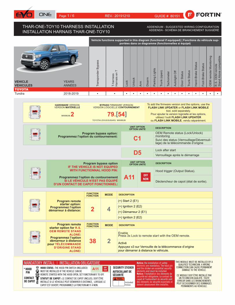
WARNING ATTENTION A11 OFF NON * HOOD PIN HOOD STATUS : THE HOOD PIN SWITCH (INCLUDED) MUST BE INSTALLED IF THE VEHICLE CAN BE REMOTE STARTED WITH THE HOOD OPEN, SET FUNCTION A11 TO OFF. CONTACT DE CAPOT SECURITY STICKER AUTOCOLLANT DE SÉCURITÉ MANDATORY INSTALL | INSTALLATION OBLIGATOIRE Notice: the installation of safety elements are mandatory. The hood pin and the sticker are essential security elements and must be installed. Notice: l'installation des éléments de sécurité est obligatoire. Le contact de capot et l'autocollant de sécurité sont des éléments de sécurité essentiels et doivent absolument être installés. THIS MODULE MUST BE INSTALLED BY A QUALIFIED TECHNICIAN. A WRONG CONNECTION CAN CAUSE PERMANENT DAMAGE TO THE VEHICLE. CE MODULE DOIT ÊTRE INSTALLÉ PAR UN TECHNICIEN QUALIFIÉ, TOUTE ERREUR DANS LES BRANCHEMENTS PEUT OCCASIONNER DES DOMMAGES PERMANENTS AU VÉHICULE. STATUT DE CAPOT : LE CONTACT DE CAPOT (INCLUS), DOIT ÊTRE INSTALLÉ SI LE VÉHICULE PEUT DÉMARRER À DISTANCE, LORSQUE LE CAPOT EST OUVERT, PROGRAMMEZ LA FONCTION A11 À NON. Included Inclus ONE REV.: 20191210 ADDENDUM - SUGGESTED WIRING CONFIGURATION ADDENDA - SCHÉMA DE BRANCHEMENT SUGGÉRÉ GUIDE # 80151 Program remote starter option for R.S. OEM REMOTE STAND ALONE: Programmez l’option démarreur à distance pour TÉLÉCOMMANDE D’ORIGINE STAND ALONE: FUNCTION FONCTION MODE DESCRIPTION 38 2 Enable Press 3x Lock to remote start with the OEM remote. Activé Appuyez x3 sur Verrouille de la télécommance d’origine pour démarrer à distance le véhicule. Program bypass option: Programmez l’option du contournement: UNIT OPTION OPTION UNITE DESCRIPTION C1 OEM Remote status (Lock/Unlock) monitoring Suivi des status (Verrouillage/Déverrouil- lage) de la télécommande d’origine HARDWARE VERSION VERSION MATÉRIELLE BYPASS FIRMWARE VERSION VERSION LOGICIELLE CONTOURNEMENT To add the firmware version and the options, use the FLASH LINK UPDATER or FLASH LINK MOBILE tool, sold separately. Pour ajouter la version logicielle et les options, utilisez l’outil FLASH LINK UPDATER ou FLASH LINK MOBILE, vendu séparément. MINIMUM 2 79. [ 54 ] TOYOTA/LEXUS/SUBARU MINIMUM Vehicle functions supported in this diagram (functional if equipped) | Fonctions du véhicule sup- portées dans ce diagramme (fonctionnelles si équipé) Transponder Bypass T-harness Harnais en T Lock Unlock Arm Disarm Parking Lights Trunk (open) Tachometer Autolight Off Door Status Trunk Status Hand-Brake Status Foot-Brake Status OEM remote Monitoring R.S. OEM remote Stand Alone compatible VEHICLE VEHICULES YEARS ANNÉES TOYOTA Tundra 2018-2019 • • • • • • • • • • • • • • • • D5 Lock after start Verrouillage après le démarrage Program remote starter option: Programmez l’option démarreur à distance: FUNCTION FONCTION MODE DESCRIPTION 2 4 (+) Start 2 (E1) (+) Ignition 2 (E2) (+) Démarreur 2 (E1) (+) Ignition 2 (E2) Program bypass option IF THE VEHICLE IS NOT EQUIPED WITH FUNCTIONNAL HOOD PIN: Programmez l’option du contournement SI LE VÉHICULE N’EST PAS ÉQUIPÉ D’UN CONTACT DE CAPOT FONCTIONNEL: UNIT OPTION OPTION UNITE DESCRIPTION A11 OFF NON Hood trigger (Output Status). Déclencheur de capot (état de sortie). THAR-ONE-TOY10 THARNESS INSTALLATION INSTALLATION HARNAIS THAR-ONE-TOY10 Page 1 / 6
Transcript of ONE Page NON - Fortin€¦ · Yellow In A1 Purple Out A2 Purple/White Out A3 Green Out A4 White Out...
WARNINGATTENTION
A11 OFFNON* HOOD
PIN
HOOD STATUS : THE HOOD PIN SWITCH (INCLUDED)MUST BE INSTALLED IF THE VEHICLE CAN BE REMOTE STARTED WITH THE HOOD OPEN, SET FUNCTION A11 TO OFF.
CONTACTDE CAPOT
SECURITY STICKERAUTOCOLLANT DE SÉCURITÉ
MANDATORY INSTALL | INSTALLATION OBLIGATOIRE Notice: the installation of safety elements are mandatory. The hood pin and the sticker are essential security elements and must be installed. Notice: l'installation des éléments de sécurité est obligatoire. Le contact de capot et l'autocollant de sécurité sont des éléments de sécurité essentiels et doivent absolument être installés.
THIS MODULE MUST BE INSTALLED BY A QUALIFIED TECHNICIAN. A WRONG
CONNECTION CAN CAUSE PERMANENT DAMAGE TO THE VEHICLE.
CE MODULE DOIT ÊTRE INSTALLÉ PAR UN TECHNICIEN QUALIFIÉ, TOUTE
ERREUR DANS LES BRANCHEMENTS PEUT OCCASIONNER DES DOMMAGES
PERMANENTS AU VÉHICULE.
STATUT DE CAPOT : LE CONTACT DE CAPOT (INCLUS), DOIT ÊTRE INSTALLÉ SI LE VÉHICULE PEUT DÉMARRER À DISTANCE, LORSQUE LE CAPOT EST OUVERT, PROGRAMMEZ LA FONCTION A11 À NON.
IncludedInclus
ONE REV.: 20191210
ADDENDUM - SUGGESTED WIRING CONFIGURATION ADDENDA - SCHÉMA DE BRANCHEMENT SUGGÉRÉ
GUIDE # 80151
Program remote starter option for R.S. OEM REMOTE STAND
ALONE:Programmez l’option démarreur à distance
pour TÉLÉCOMMANDE D’ORIGINE STAND
ALONE:
FUNCTIONFONCTION MODE DESCRIPTION
38 2Enable Press 3x Lock to remote start with the OEM remote.
ActivéAppuyez x3 sur Verrouille de la télécommance d’origine pour démarrer à distance le véhicule.
Program bypass option:Programmez l’option du contournement:
UNIT OPTIONOPTION UNITE DESCRIPTION
C1OEM Remote status (Lock/Unlock) monitoringSuivi des status (Verrouillage/Déverrouil-lage) de la télécommande d’origine
HARDWARE VERSIONVERSION MATÉRIELLE
BYPASS FIRMWARE VERSIONVERSION LOGICIELLE CONTOURNEMENT
To add the firmware version and the options, use the FLASH LINK UPDATER or FLASH LINK MOBILE
tool, sold separately.Pour ajouter la version logicielle et les options,
utilisez l’outil FLASH LINK UPDATER ou FLASH LINK MOBILE, vendu séparément.
MINIMUM 2 79.[54]TOYOTA/LEXUS/SUBARU MINIMUM
Vehicle functions supported in this diagram (functional if equipped) | Fonctions du véhicule sup-portées dans ce diagramme (fonctionnelles si équipé)
Tran
spon
der B
ypas
s
T-ha
rnes
s H
arna
is e
n T
Lock
Unl
ock
Arm
Dis
arm
Park
ing
Ligh
ts
Trun
k (o
pen)
Tach
omet
er
Auto
light
Off
Doo
r Sta
tus
Trun
k S
tatu
s
Han
d-B
rake
Sta
tus
Foot
-Bra
ke S
tatu
s
OEM
rem
ote
Mon
itorin
g
R.S
. OEM
rem
ote
Sta
nd A
lone
com
patib
le
VEHICLEVEHICULES
YEARS ANNÉES
TOYOTATundra 2018-2019 • • • • • • • • • • • • • • • •
D5 Lock after startVerrouillage après le démarrage
Program remote starter option:
Programmez l’option démarreur à distance:
FUNCTIONFONCTION MODE DESCRIPTION
2 4(+) Start 2 (E1)
(+) Ignition 2 (E2)
(+) Démarreur 2 (E1)
(+) Ignition 2 (E2)
Program bypass option IF THE VEHICLE IS NOT EQUIPED
WITH FUNCTIONNAL HOOD PIN:
Programmez l’option du contournementSI LE VÉHICULE N’EST PAS ÉQUIPÉ
D’UN CONTACT DE CAPOT FONCTIONNEL:
UNIT OPTIONOPTION UNITE DESCRIPTION
A11 OFFNON
Hood trigger (Output Status).
Déclencheur de capot (état de sortie).
THAR-ONE-TOY10 THARNESS INSTALLATION INSTALLATION HARNAIS THAR-ONE-TOY10
Page 1 / 6
This guide may change without notice. See www.fortin.ca for latest version.Ce guide peut faire l’objet de changement sans préavis. Voir www.fortin.ca pour la récente version.
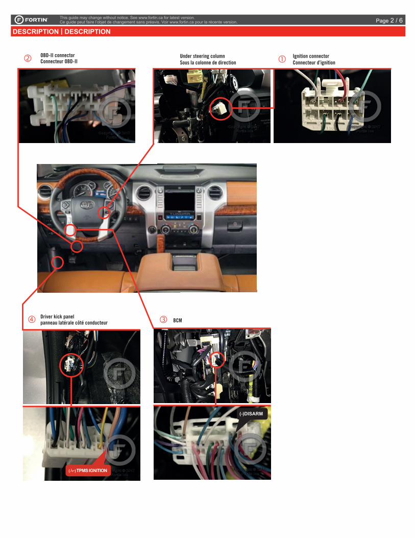
DESCRIPTION | DESCRIPTION
Driver kick panelpanneau latérale côté conducteur
( ) TPMS IGNITION
Under steering columnSous la colonne de direction
Ignition connectorConnecteur d’ignition
BCM
(-)DISARM
OBD-II connectorConnecteur OBD-II
Page 2 / 6
Yellow In A1Purple Out A2
Purple/White Out A3Green Out A4White Out A5
Orange Out A6Orange/Black Out A7
Dk.Blue Out A8Red/Blue In A9
Lt.Blue/Black In/Out A10Black In A11Pink Out A12
Yellow/Black Out A13Brown/White In A14
Pink/Black In A15Purple/Yellow In/Out A16Green/White In/Out A17
Green/Red In/Out A18White/Black Out A19
Lt.Blue In/Out A20
C5 BrownC4 Gray/BlackC3 GrayC2 Orange/BrownC1 Orange/Green
D6 White/RedD5 White/BlueD4 White/GreenD3 Yellow/RedD2 Yellow/BlueD1 Yellow/Green
White Out E1Orange Out E2
Red In E3Black In E4Pink In/Out E5
Yellow Out E6
This guide may change without notice. See www.fortin.ca for latest version.Ce guide peut faire l’objet de changement sans préavis. Voir www.fortin.ca pour la récente version.
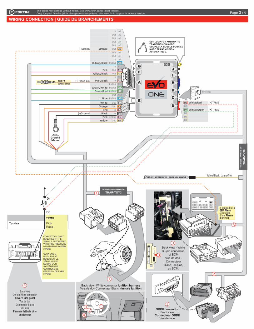
WIRING CONNECTION | GUIDE DE BRANCHEMENTS
(-) Hood pinHOOD PIN CONTACT CAPOT
CUT LOOP FOR AUTOMATIC TRANSMISSION MODE.COUPEZ LA BOUCLE POUR LE MODE TRANSMISSION AUTOMATIQUE.
(~)TPMS
(~)TPMS
(-)Ground
(-)Disarm
A2A3A4A5A6A7A8A9
A10A11A12A13A14A15A16A17A18A19A20
E1E2E3
E4E5E6
C5C4C3C2C1
D6D5D4D3D2D1
A1
D1D2D3
D5
C1C2
C5
A19
A16
A14
A11
A9A8A7
A5A4A3A2
A1
ISOLATE NOT CONNECTED ---------------------ISOLER NON BRANCHÉ
Back view White connector Ignition harnessVue de dos Connecteur Blanc Harnais Ignition
5 PIN CONN.
OBDII connectorFront view
Connecteur OBDIIVue de face
GroundMasse
Yellow/Black Jaune/Noir
T-HARNESS - HARNAIS EN T
T-H
AR
NES
S - H
AR
NA
IS E
N T
Back view - White 30-pin connector,
at BCMVue de dos - Connecteur
Blanc, 30-pins, au BCM.
D4
D6
Tundra
CU
T
PinkRose
TPMS
Back view20-pin White connector
Driver’s kick panelVue de dos
Connecteur Blanc 20-pins
Panneau latérale côté conducteur
21 3 4 5 6
13
1110
12 1514
7 8 9
16 17 18 19 20
CONNECTION ONLY REQUIRED IF THE VEHICLE IS EQUIPPED WITH TIRE PRESSURE MONITORING SYSTEM (TPMS).
CONNEXION UNIQUEMENT REQUISE SI LE VÉHICULE EST ÉQUIPÉ D'UN SYSTÈMES DE CONTRÔLE DE PRESSION DE PNEU (TPMS).
1
10
23456
789
192021
17 16 1415 13 1218 11
27 25 24 23 222930 28 26
2
If equiped with OEM AlarmSi équippé d’une Alarmed’origine
THA
R-T
Y20
THAR-TOY2
Page 3 / 6
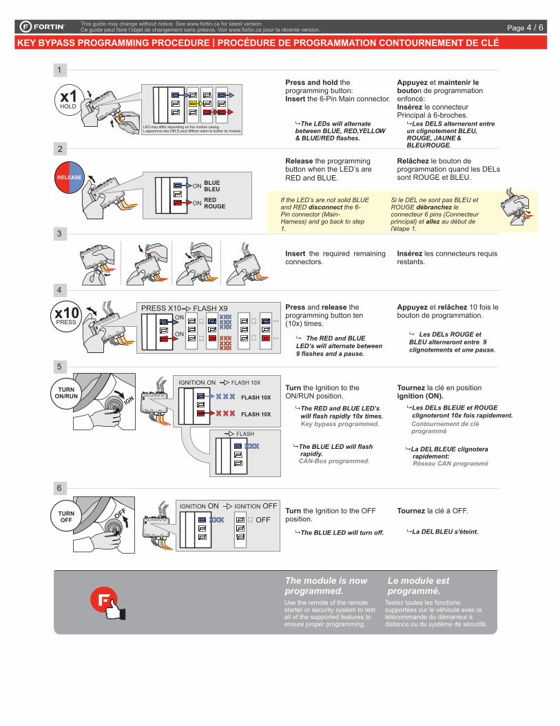
Insert the required remainingconnectors.
2
3
4
Insérez les connecteurs requisrestants.
LOCK
ACC ON
PUSH
START
IGN
Turn the Ignition to theON/RUN position.
6
Turn the Ignition to the OFFposition.
LOCK
ACC ON
PUSH
START
OFF
Tournezignition (ON).
la clé en position
Tournez la clé à OFF.
The RED and BLUE LED’s will flash rapidly 10x times.
The BLUE LED will flash rapidly.
Key bypass programmed.
CAN-Bus programmed.
Les DELs BLEUE et ROUGE clignoteront 10x fois rapidement.
La DEL BLEUE clignotera rapidement:
Contournement de cléprogrammé.
Réseau CAN programmé.
The BLUE LED will turn off. La DEL BLEU s'éteint.
5
The module is nowprogrammed.
Le module estprogrammé.
Use the remote of the remotestarter or security system to testall of the supported features toensure proper programming.
Testez toutes les fonctionssupportées sur le véhicule avec latélécommande du démarreur àdistance ou du système de sécurité.
1
PRESS
TURNON/RUN
TURNOFF
Press and hold
Insert
theprogramming button:
the 6-Pin Main connector.
Appuyez maintenir lebouto
Insérez
etn de programmation
enfoncé:le connecteur
Principal à 6-broches. The LEDs will alternatebetween BLUE, RED,YELLOW& BLUE/RED flashes.
Les DELS alterneront entreun clignotement BLEU,ROUGE, JAUNE &BLEU/ROUGE.
x1HOLD
A
E
FG
J
I
H
B
C
D
LED may differ depending on the module casing.apparence des DELS peut différer selon le boîtier du module.
A
E
FG
J
I
H
B
C
D
A
E
FG
J
I
H
B
C
D
A
E
FG
J
I
H
B
C
D
A
E
FG
J
I
H
B
C
D
A EFGJ I H B C D
FLASH 10XN ON
FLASH 10X
FLASH
FLASH 10X
A EFGJ I H B C D
IGNITION ON IGNITION OFF
OFF
IGNITIO
Ne pas utiliser la clé grise.Do not use the grey key.
Release the programmingbutton when the LED’s areRED and BLUE.
Relâchez le bouton deprogrammation quand les DELssont ROUGE et BLEU.
Si le DEL ne sont pas BLEU etROUGE leconnecteur 6 pins (Connecteurprincipal) et au début del'étape 1.
débranchez
allez
If the LED’s are not solid BLUEand RED the 6-Pin connector (Main-Harness) and go back to step1.
disconnect
RELEASE
A
E
FG
J
I
HB
C
D
ON BLUEBLEU
ON REDROUGE
A
E
FG
J
I
HB
C
D
Press releaseand theprogramming button ten(10x) times.
Appuyez relâchezet 10 fois lebouton de programmation.x10 Les DELs ROUGE et BLEU alterneront entre 9 clignotements et une pause.
The RED and BLUE LED’s will alternate between 9 flashes and a pause.
A
E
FG
J
I
H
B
C
D
ON
PRESS X10ON
FLASH X9
...
...
This guide may change without notice. See www.fortin.ca for latest version.Ce guide peut faire l’objet de changement sans préavis. Voir www.fortin.ca pour la récente version.
KEY BYPASS PROGRAMMING PROCEDURE | PROCÉDURE DE PROGRAMMATION CONTOURNEMENT DE CLÉPage 4 / 6
This guide may change without notice. See www.fortin.ca for latest version.Ce guide peut faire l’objet de changement sans préavis. Voir www.fortin.ca pour la récente version.
REMOTE STARTER PROGRAMMING PROCEDURE | PROCÉDURE DE PROGRAMMATION DU DÉMARREUR À DISTANCE
REFER TO THE QUICK INSTALL GUIDE INCLUDED WITH THE MODULE FOR THE REMOTE STARTER PROGRAMMING.
RÉFÉREZ-VOUS AU GUIDE D’INSTALLATION RAPIDE INCLUS AVEC LE MODULE POUR LA PROGRAMMATION DU DÉMARREUR À DISTANCE.
Page 5 / 6

Service No : 000 102 04 2536
Date: xx-xx
INTERFACE MODULE
Made in CanadaPATENTS PENDING US: 2007-228827-A1
www.fortinbypass.com
HARDWARE VERSION FIRMWARE VERSION
Module label | Étiquette sur le module
Notice: Updated Firmware and Installation GuidesUpdated fi rmware and installation guides are posted on our web site on a regular basis. We recommend that you update this module to the latest fi rmware and download the latest installation guide(s) prior to the installation of this product.
Notice: Mise à jour microprogramme et Guides d’installationsDes mises à jour du Firmware (microprogramme) et des guides d’installation sont mis en ligne régulièrement. Vérifi ez que vous avez bien la dernière version logiciel et le dernier guide d’installation avant l’installation de ce produit.
WARNINGThe information on this sheet is provided on an (as is) basis with no representation or warranty of accuracy whatsoever. It is the sole responsibility of the installer to check and verify any circuit before connecting to it. Only a computer safe logic probe or digital multimeter should be used. FORTIN ELECTRONIC SYSTEMS assumes absolutely no liability or responsibility whatsoever pertaining to the accuracy or currency of the information supplied. The installation in every case is the sole responsibility of the installer performing the work and FORTIN ELECTRONIC SYSTEMS assumes no liability or responsibility whatsoever resulting from any type of installation, whether performed properly, improperly or any other way. Neither the manufacturer or distributor of this module is responsible of damages of any kind indirectly or directly caused by this module, except for the replacement of this module in case of manufacturing defects. This module must be installed by qualifi ed technician. The information supplied is a guide only. This instruction guide may change without notice. Visit www.fortinbypass.com to get the latest version.
MISE EN GARDE L’information de ce guide est fournie sur la base de représentation (telle quelle) sans aucune garantie de précision et d’exactitude. Il est de la seule responsabilité de l’installateur de vérifi er tous les fi ls et circuits avant d’effectuer les connexions. Seuls une sonde logique ou un multimètre digital doivent être utilisés. FORTIN SYSTÈMES ÉLECTRONIQUES n’assume aucune responsabilité de l’exactitude de l’information fournie. L’installation (dans chaque cas) est la responsabilité de l’installateur effectuant le travail. FORTIN SYSTÈMES ÉLECTRONIQUES n’assume aucune responsabilité suite à l’installation, que celle-ci soit bonne, mauvaise ou de n’importe autre type. Ni le manufacturier, ni le distributeur ne se considèrent responsables des dommages causés ou ayant pu être causés, indirectement ou directement, par ce module, excepté le remplacement de ce module en cas de défectuosité de fabrication. Ce module doit être installé par un technicien qualifi é. L’information fournie dans ce guide est une suggestion. Ce guide d’instruction peut faire l’objet de changement sans préavis. Consultez le www.fortinbypass.com pour voir la plus récente version.
Copyright © 2006-2018, FORTIN AUTO RADIO INC ALL RIGHTS RESERVED PATENT PENDING
TECH SUPPORTTél: 514-255-HELP (4357) 1-877-336-7797
ADDENDUM GUIDEWEB UPDATE | MISE À JOUR INTERNET
www.fortinbypass.com
ONE
Page 6 / 6