One-millimeter Heat Pipe and Application to Cooling … One-millimeter Heat Pipe and Application to...
5
34 One-millimeter Heat Pipe and Application to Cooling Module for Electronic Devices Yoji Kawahara, 1 Masataka Mochizuki, 2 Yuji Saito, 1 Yasuhiro Horiuchi, 3 and Mohammad Shahed Ahamed 1 Electronic devices are becoming compact with enhanced performance. Therefore, it becomes a challenging task to provide the cooling solutions for these compact devices with high-density heat generation. Regarding this challenge, thin flat heat pipe can play a vital role. In the present study, experimental investigation of the thin flat heat pipe with a thickness of 1.0 mm has been performed. In this paper, different kinds of new fiber wick structures consisting of a combination of copper fine fibers and axial grooves are investigated. Thin heat pipe having these new wick structures showed highly improved thermal performance as compared with that having normal wick structures. The effect of length, thermal test mode, and bending on the thin heat pipe thermal performance has been studied. From the present study, it is found that maximum heat transfer capability of the present 1.0-mm-thin heat pipe is 11 W, with the thermal resistance of 0.6 °C/W. Bending has reasonable effect on the thermal performance of heat pipe. Besides, thermal performance of remote heat exchanger fabricated by using the developed thin heat pipe has been investigated. Twenty-five watts of heat can be transferred by using the present assembly. 1. Introduction Recently, a number of cooling modules consisting of the thin heat pipes are used for cooling of compact electronic devices such as notebook PC. At present, thinner heat pipe with a minimum thickness of 2 mm is commonly used. With enhanced performance of electronic devices, heat generation and density factor are increasing. Therefore, the thin heat pipe, which has a thickness of less than 2 mm, cannot satisfy the thermal performance and makes it difficult for practi- cal use. However, ultrathin heat pipe such as 1-mm- thick heat pipe has its role to play in resolving the limitation of thermal design in electronic devices dra- matically. Owing to the growing demand of ultrathin heat pipes, in the present study the authors try to de- velop ultrathin 1-mm-thick heat pipes. In practice, when we fabricated 1-mm-thick heat pipe using normal wick structure available from our mass-production product, maximum heat transfer, Qmax, was only around 5 W, and heat pipe thermal resistance was around 5°C/W. 1) The performance was not sufficient enough for its practical use. Because of the limitation of inner space for 1-mm heat pipe, it is necessary to miniaturize wick space and keep the vapor space as wide as possible to improve the thermal performance. Moreover, high-perfor- mance wick structure that possesses a good reflux performance is necessary to prevent the dry-out and increase the Qmax. In this paper, the performance evaluation result of 1-mm heat pipe using different kinds of new wick structures is reported, that is small space and good re- flux performance. Besides, the thermal performance evaluation result of 1-mm heat pipe remote heat ex- change assembly is reported in this paper. 2. Heat pipe structure Figure 1 shows the thin flat heat pipe made of cop- per pipe with original diameter of 5 mm. The present thin heat pipe is straight shaped, which has a rectangular cross section of 1.0 ¥ 7.43 mm and different heat transfer lengths of 100, 120, 150, 180, and 200 mm. 3. Wick structure Our standard wick structure named “composite 1 Thermal Technology Division Engineering Department 2 Thermal Technology Division 3 Fujikura Electronics (Thailand) Ltd. Thermal Solution Division Fig. 1 . One-millimeter-thick heat pipe. 7.43mm width 1.00mm thickness
Transcript of One-millimeter Heat Pipe and Application to Cooling … One-millimeter Heat Pipe and Application to...
34
One-millimeter Heat Pipe and Application to Cooling Module for Electronic Devices
Yoji Kawahara,1 Masataka Mochizuki,2 Yuji Saito,1
Yasuhiro Horiuchi,3 and Mohammad Shahed Ahamed1
Electronic devices are becoming compact with enhanced performance. Therefore, it becomes a challenging task to provide the cooling solutions for these compact devices with high-density heat generation. Regarding this challenge, thin flat heat pipe can play a vital role. In the present study, experimental investigation of the thin flat heat pipe with a thickness of 1.0 mm has been performed. In this paper, different kinds of new fiber wick structures consisting of a combination of copper fine fibers and axial grooves are investigated. Thin heat pipe having these new wick structures showed highly improved thermal performance as compared with that having normal wick structures. The effect of length, thermal test mode, and bending on the thin heat pipe thermal performance has been studied. From the present study, it is found that maximum heat transfer capability of the present 1.0-mm-thin heat pipe is 11 W, with the thermal resistance of 0.6 °C/W. Bending has reasonable effect on the thermal performance of heat pipe. Besides, thermal performance of remote heat exchanger fabricated by using the developed thin heat pipe has been investigated. Twenty-five watts of heat can be transferred by using the present assembly.
1. IntroductionRecently, a number of cooling modules consisting of
the thin heat pipes are used for cooling of compact electronic devices such as notebook PC. At present, thinner heat pipe with a minimum thickness of 2 mm is commonly used. With enhanced performance of electronic devices, heat generation and density factor are increasing. Therefore, the thin heat pipe, which has a thickness of less than 2 mm, cannot satisfy the thermal performance and makes it difficult for practi-cal use. However, ultrathin heat pipe such as 1-mm-thick heat pipe has its role to play in resolving the limitation of thermal design in electronic devices dra-matically. Owing to the growing demand of ultrathin heat pipes, in the present study the authors try to de-velop ultrathin 1-mm-thick heat pipes.
In practice, when we fabricated 1-mm-thick heat pipe using normal wick structure available from our mass-production product, maximum heat transfer, Qmax, was only around 5 W, and heat pipe thermal resistance was around 5°C/W.1) The performance was not sufficient enough for its practical use.
Because of the limitation of inner space for 1-mm heat pipe, it is necessary to miniaturize wick space and keep the vapor space as wide as possible to improve the thermal performance. Moreover, high-perfor-mance wick structure that possesses a good reflux
performance is necessary to prevent the dry-out and increase the Qmax.
In this paper, the performance evaluation result of 1-mm heat pipe using different kinds of new wick structures is reported, that is small space and good re-flux performance. Besides, the thermal performance evaluation result of 1-mm heat pipe remote heat ex-change assembly is reported in this paper.
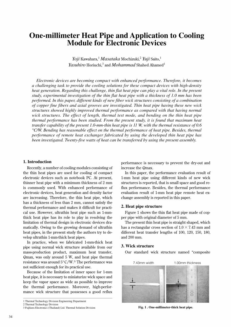
2. Heat pipe structureFigure 1 shows the thin flat heat pipe made of cop-
per pipe with original diameter of 5 mm.The present thin heat pipe is straight shaped, which
has a rectangular cross section of 1.0 ¥ 7.43 mm and different heat transfer lengths of 100, 120, 150, 180, and 200 mm.
3. Wick structureOur standard wick structure named “composite
1 Thermal Technology Division Engineering Department2 Thermal Technology Division3 Fujikura Electronics (Thailand) Ltd. Thermal Solution Division Fig. 1 . One-millimeter-thick heat pipe.
7.43mm width 1.00mm thickness
Fujikura Technical Review, 2011 35
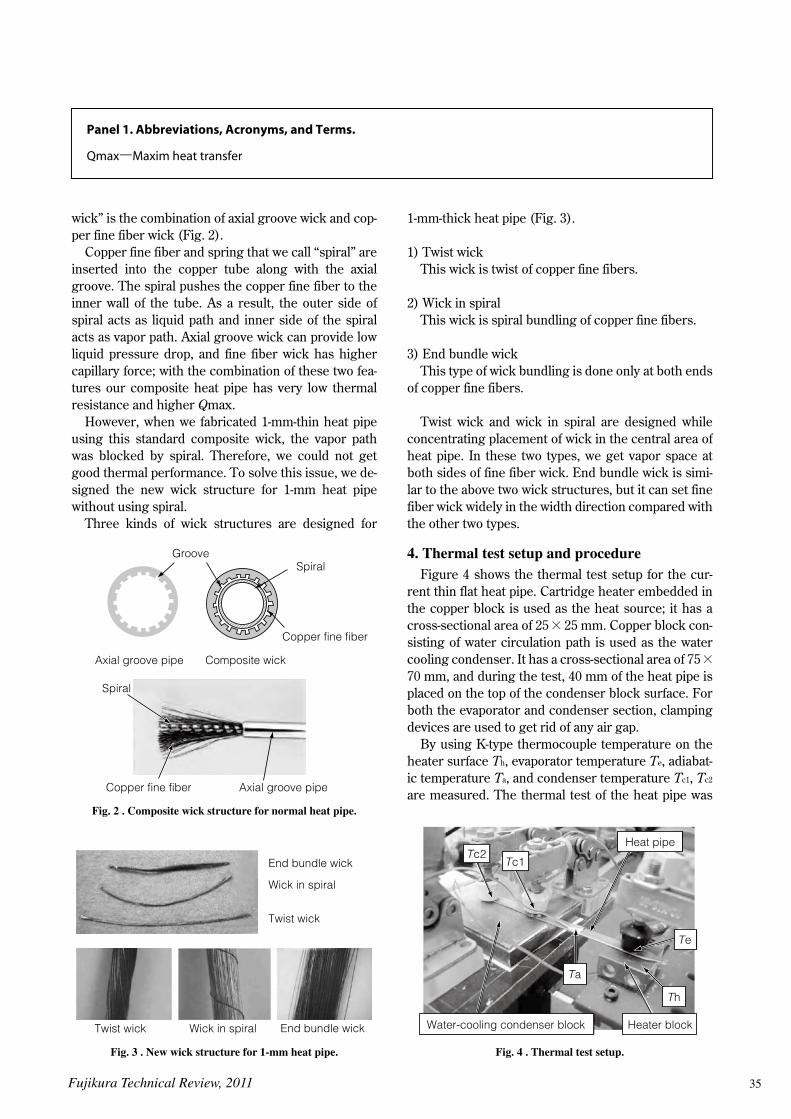
wick” is the combination of axial groove wick and cop-per fine fiber wick (Fig. 2).
Copper fine fiber and spring that we call “spiral” are inserted into the copper tube along with the axial groove. The spiral pushes the copper fine fiber to the inner wall of the tube. As a result, the outer side of spiral acts as liquid path and inner side of the spiral acts as vapor path. Axial groove wick can provide low liquid pressure drop, and fine fiber wick has higher capillary force; with the combination of these two fea-tures our composite heat pipe has very low thermal resistance and higher Qmax.
However, when we fabricated 1-mm-thin heat pipe using this standard composite wick, the vapor path was blocked by spiral. Therefore, we could not get good thermal performance. To solve this issue, we de-signed the new wick structure for 1-mm heat pipe without using spiral.
Three kinds of wick structures are designed for
1-mm-thick heat pipe (Fig. 3).
1) Twist wickThis wick is twist of copper fine fibers.
2) Wick in spiralThis wick is spiral bundling of copper fine fibers.
3) End bundle wickThis type of wick bundling is done only at both ends
of copper fine fibers.
Twist wick and wick in spiral are designed while concentrating placement of wick in the central area of heat pipe. In these two types, we get vapor space at both sides of fine fiber wick. End bundle wick is simi-lar to the above two wick structures, but it can set fine fiber wick widely in the width direction compared with the other two types.
4. Thermal test setup and procedureFigure 4 shows the thermal test setup for the cur-
rent thin flat heat pipe. Cartridge heater embedded in the copper block is used as the heat source; it has a cross-sectional area of 25 ¥ 25 mm. Copper block con-sisting of water circulation path is used as the water cooling condenser. It has a cross-sectional area of 75 ¥ 70 mm, and during the test, 40 mm of the heat pipe is placed on the top of the condenser block surface. For both the evaporator and condenser section, clamping devices are used to get rid of any air gap.
By using K-type thermocouple temperature on the heater surface Th, evaporator temperature Te, adiabat-ic temperature Ta, and condenser temperature Tc1, Tc2 are measured. The thermal test of the heat pipe was
Fig. 2 . Composite wick structure for normal heat pipe.
GrooveSpiral
Copper fine fiber
Axial groove pipe
Axial groove pipe
Copper fine fiber
Composite wick
Spiral
Fig. 3 . New wick structure for 1-mm heat pipe.
End bundle wick
Wick in spiral
Twist wick
End bundle wickWick in spiralTwist wick
Fig. 4 . Thermal test setup.
Heater block
Heat pipe
Te
Ta
Th
Tc1Tc2
Water-cooling condenser block
Panel 1. Abbreviations, Acronyms, and Terms.
Qmax–Maxim heat transfer
36
performed in the horizontal mode with evaporator and condenser at the same level. And temperatures at all the points are recorded until the temperature at the evaporator becomes steady. All the thermal tests have been done with a fixed adiabatic temperature. In this paper, we mentioned this temperature as the operat-ing temperature of the heat pipe. To find out the Qmax of each heat pipe, heat input is increased by 1 W until dry-out occurs.
5. Results and discussionIn this present study, the authors have focused on
determining the effect of the wick structures, heat pipe length, thermal test mode, and bending on the ther-mal performance of 1.0-mm-thin flat heat pipe. Evalua-tion of performance is done based on the heat pipe thermal resistance, Rhp, that is calculated by the follow-ing equation:
Rhp = Re-c = (Te - Tc2)/Q ……… (1)
Here, Q is the heat flow rate applied to the heater block.
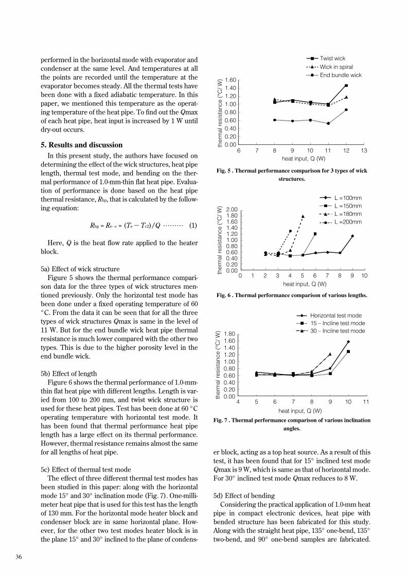
5a) Effect of wick structureFigure 5 shows the thermal performance compari-
son data for the three types of wick structures men-tioned previously. Only the horizontal test mode has been done under a fixed operating temperature of 60 °C. From the data it can be seen that for all the three types of wick structures Qmax is same in the level of 11 W. But for the end bundle wick heat pipe thermal resistance is much lower compared with the other two types. This is due to the higher porosity level in the end bundle wick.
5b) Effect of lengthFigure 6 shows the thermal performance of 1.0-mm-
thin flat heat pipe with different lengths. Length is var-ied from 100 to 200 mm, and twist wick structure is used for these heat pipes. Test has been done at 60 °C operating temperature with horizontal test mode. It has been found that thermal performance heat pipe length has a large effect on its thermal performance. However, thermal resistance remains almost the same for all lengths of heat pipe.
5c) Effect of thermal test modeThe effect of three different thermal test modes has
been studied in this paper: along with the horizontal mode 15° and 30° inclination mode (Fig. 7). One-milli-meter heat pipe that is used for this test has the length of 130 mm. For the horizontal mode heater block and condenser block are in same horizontal plane. How-ever, for the other two test modes heater block is in the plane 15° and 30° inclined to the plane of condens-
er block, acting as a top heat source. As a result of this test, it has been found that for 15° inclined test mode Qmax is 9 W, which is same as that of horizontal mode. For 30° inclined test mode Qmax reduces to 8 W.
5d) Effect of bendingConsidering the practical application of 1.0-mm heat
pipe in compact electronic devices, heat pipe with bended structure has been fabricated for this study. Along with the straight heat pipe, 135° one-bend, 135° two-bend, and 90° one-bend samples are fabricated.
Fig. 5 . Thermal performance comparison for 3 types of wick structures.
0.000.200.400.600.801.001.201.401.60
heat input, Q (W)
ther
mal
res
ista
nce
(∞C
/ W)
11 12 136 7 8 9 10
Twist wick
End bundle wickWick in spiral
Fig. 7 . Thermal performance comparison of various inclination angles.
0.000.200.400.600.801.001.201.401.601.80
heat input, Q (W)
ther
mal
res
ista
nce
(°C
/ W)
9 10 114 5 6 7 8
15 – Incline test mode30 – Incline test mode
Horizontal test mode
Fig. 6 . Thermal performance comparison of various lengths.
0.000.200.400.600.801.001.201.401.601.802.00
heat input, Q (W)
ther
mal
res
ista
nce
(°C
/ W)
1 20 3 4 65 7 8 9 10
L =200mm
L =150mmL =180mm
L =100mm
Fujikura Technical Review, 2011 37
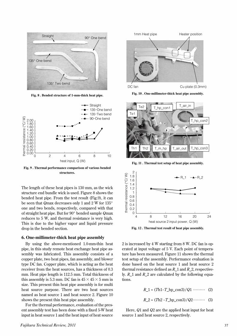
The length of these heat pipes is 130 mm, as the wick structure end bundle wick is used. Figure 8 shows the bended heat pipe. From the test result (Fig.9), it can be seen that Qmax decreases only 1 and 2 W for 135° one and two bends, respectively, compared with that of straight heat pipe. But for 90° bended sample Qmax reduces to 5 W, and thermal resistance is very high. This is due to the higher vapor and liquid pressure drop in the bended section.
6. One-millimeter-thick heat pipe assemblyBy using the above-mentioned 1.0-mm-thin heat
pipe, in this study remote heat exchange heat pipe as-sembly was fabricated. This assembly consists of a copper plate, two heat pipes, fan assembly, and blower type DC fan. Copper plate, which is acting as the heat receiver from the heat sources, has a thickness of 0.3 mm. Heat pipe length is 112.5 mm. Total thickness of this assembly is 5.3 mm. DC fan is 45 ¥ 45 ¥ 5 mm in size. This present thin heat pipe assembly is for multi heat source purpose. There are two heat sources named as heat source 1 and heat source 2. Figure 10 shows the present thin heat pipe assembly.
For the thermal performance, evaluation of the pres-ent assembly test has been done with a fixed 5-W heat input in heat source 1 and the heat input of heat source
2 is increased by 4 W starting from 8 W. DC fan is op-erated at input voltage of 5 V. Each point of tempera-ture has been measured. Figure 11 shows the thermal test setup of the assembly. Performance evaluation is done based on the heat source 1 and heat source 2 thermal resistance defined as R_1 and R_2, respective-ly. R_1 and R_2 are calculated by the following equa-tions.
R_1 = (Th1−T_hp_con3)/Q1 ……… (2)
R_2 = (Th2 −T_hp_con3)/Q2 ……… (3)
Here, Q1 and Q2 are the applied heat input for heat source 1 and heat source 2, respectively.
Fig. 9 . Thermal performance comparison of various bended structures.
0.000.200.400.600.801.001.201.401.601.802.00
heat input, Q (W)
ther
mal
res
ista
nce
(∞C
/ W)
100 2 4 6 8
Straight135–One bend135–Two bend90–One bend
Fig. 10 . One-millimeter-thick heat pipe assembly.
Heater position
Cu plate (0.3mm)DC fan
1mm Heat pipe
Fig. 11 . Thermal test setup of heat pipe assembly.
Te1
Te2 T_hp_con1
T_hp_con2
T_hp_con3T_air_outTh2 T_m_hpTh1
T_air_in
Fig. 12 . Thermal test result of heat pipe assembly.
00.20.40.60.8
11.21.41.61.8
2
heat source 2 input power, Q (W)
ther
mal
res
ista
nce
(°C
/ W)
244 8 12 16 20
R_2R_1
Fig. 8 . Bended structure of 1-mm-thick heat pipe.
Straight 90° One bend
135° One bend
135° Two bend

38
Figure 12 shows the thermal performance of the present assembly. It can be seen that even after in-creasing Q2 to 20 W no dry-out occurs for the present assembly. So, the present assembly can transfer 25 W of heat.
7. ConclusionOne-millimeter-thin heat pipe has been successfully
developed. Experimental investigations for practical application of thin heat pipe have also been done. This study concludes as follows:i) The new fiber wick structure provides sufficient cap-
illary head, permeability, as well as enough vapor space for the circulation of working fluid inside the 1.0-mm-thin flat heat pipe.
ii) Maximum heat transfer capability for the present 1.0-mm-thin heat pipe is 11 W with a heat pipe ther-
mal resistance of 0.6°C/W.iii) Presently developed thin heat pipe is capable of
working in a top heat source application, and suffi-cient thermal performance can be achieved for bended structure.
iv) One-millimeter heat pipe assembly can transfer 25 W of heat with a low thermal resistance.
On the basis of the above performance, it can be concluded that the presently fabricated thin flat heat pipe and the heat pipe assembly will find applications in the cooling of the compact electronic devices.
Reference
1) Ahamed, M. S., et al. “Experimental study of thin flat heat
pipe with a special fiber wick structure”, 9th International
Heat Pipe Symposium, 2008, Kualalumpur, Malaysia