One-DOF Superimposed Rigid Origami with Multiple...
9
1 SCIENTIFIC REPORTS | 6:36883 | DOI: 10.1038/srep36883 www.nature.com/scientificreports One-DOF Superimposed Rigid Origami with Multiple States Xiang Liu 1 , Joseph M. Gattas 2 & Yan Chen 1,3 Origami-inspired engineering design is increasingly used in the development of self-folding structures. The majority of existing self-folding structures either use a bespoke crease pattern to form a single structure, or a universal crease pattern capable of forming numerous structures with multiple folding steps. This paper presents a new approach whereby multiple distinct, rigid-foldable crease patterns are superimposed in the same sheet such that kinematic independence and 1-DOF mobility of each individual pattern is preserved. This is enabled by the cross-crease vertex, a special configuration consisting of two pairs of collinear crease lines, which is proven here by means of a kinematic analysis to contain two independent 1-DOF rigid-foldable states. This enables many new origami-inspired engineering design possibilities, with two explored in depth: the compact folding of non-flat-foldable structures and sequent folding origami that can transform between multiple states without unfolding. Origami-inspired engineering is to apply origami science and technology to the design of engineering struc- tures or devices with remarkable performance characteristics. Applications have been developed across most engineering disciplines, with examples including space structures 1,2 , deployable shelters 3 , sandwich panels 4–6 , meta-materials 7,8 , medical implants 9,10 , and automobile components 11,12 . Many of these applications utilize a rigid-foldable origami pattern, which can fold without twisting or stretching of component panels and thus can be folded from rigid engineering sheet materials 13 . A substantial body of research into understanding the mathemat- ics and kinematics of rigid-foldable origami patterns has enabled the above engineering explorations 14,15 . ese have shown that conditions for rigid-foldability and the degrees of freedom (DOF) are determined by the geom- etry of the origami crease pattern, a network of folding lines that are placed in a sheet and intersect at vertices 16 . Properties such as, the flat-foldability and large areal reduction ratio are also of great importance in practice 17 . Yet, not all the crease patterns offer a compactly flat-folded configuration and even when such a configuration is achieved, the areal reduction ratio may be limited by the geometric parameters of the pattern design. Most existing crease patterns are for a solo pattern, for example the Miura-ori (rigid with 1-DOF 18 ) or the waterbomb tessellation (rigid with multi-DOF 19 ). For these, the folding process and the folded shape are clearly pre-defined by the crease patterns. ere are, nevertheless, some exceptions. For example, two sets of patterns have been integrated on printed circuit boards in a Latin-cross shape without intersection such that it can be folded into a pentahedron or an octahedron, which is controlled by the actuation at each folding line through soſtware and hardware 20,21 . A ‘universal’ crease pattern has also been investigated that can be dynamically pro- grammed into different shapes by folding a subset of available creases, which is a multi-DOF process with multiple folding steps. e order of the folded states has to be followed strictly in order to obtain the desired configurations in which a programmable origami is applied 22 . In this paper, we propose a fundamentally new method for generation of multiple 1-DOF rigid-foldable configurations from pre-defined crease patterns. e method leverages the existing knowledge surrounding rigid-foldability to enable crease patterns of different 1-DOF rigid-foldable states to be embedded within a single sheet, such that kinematic-independence is preserved. Sheets can thus be created that contain multiple states with different or complementary functionality and substantial potential for application in origami-inspired engineer- ing design. Results Superimposed rigid-foldable patterns. Shown in Fig. 1a are two origami patterns. e red pattern, S 1 , forms a single-curved surface and the black one, S 2 , forms a planar surface, both with 1-DOF rigid-foldability. S 1 and S 2 crease patterns are superimposed on top of each other within the same sheet to form the crease pattern of 1 School of Mechanical Engineering, Tianjin University, Tianjin 300072, China. 2 School of Civil Engineering, University of Queensland, St Lucia, QLD 4072, Australia. 3 Key Laboratory of Mechanism Theory and Equipment Design of Ministry of Education, Tianjin University, Tianjin 300072, China. Correspondence and requests for materials should be addressed to Y.C. (email: [email protected]) Received: 24 July 2016 Accepted: 24 October 2016 Published: 10 November 2016 OPEN
Transcript of One-DOF Superimposed Rigid Origami with Multiple...
1Scientific RepoRts | 6:36883 | DOI: 10.1038/srep36883
www.nature.com/scientificreports
One-DOF Superimposed Rigid Origami with Multiple StatesXiang Liu1, Joseph M. Gattas2 & Yan Chen1,3
Origami-inspired engineering design is increasingly used in the development of self-folding structures. The majority of existing self-folding structures either use a bespoke crease pattern to form a single structure, or a universal crease pattern capable of forming numerous structures with multiple folding steps. This paper presents a new approach whereby multiple distinct, rigid-foldable crease patterns are superimposed in the same sheet such that kinematic independence and 1-DOF mobility of each individual pattern is preserved. This is enabled by the cross-crease vertex, a special configuration consisting of two pairs of collinear crease lines, which is proven here by means of a kinematic analysis to contain two independent 1-DOF rigid-foldable states. This enables many new origami-inspired engineering design possibilities, with two explored in depth: the compact folding of non-flat-foldable structures and sequent folding origami that can transform between multiple states without unfolding.
Origami-inspired engineering is to apply origami science and technology to the design of engineering struc-tures or devices with remarkable performance characteristics. Applications have been developed across most engineering disciplines, with examples including space structures1,2, deployable shelters3, sandwich panels4–6, meta-materials7,8, medical implants9,10, and automobile components11,12. Many of these applications utilize a rigid-foldable origami pattern, which can fold without twisting or stretching of component panels and thus can be folded from rigid engineering sheet materials13. A substantial body of research into understanding the mathemat-ics and kinematics of rigid-foldable origami patterns has enabled the above engineering explorations14,15. These have shown that conditions for rigid-foldability and the degrees of freedom (DOF) are determined by the geom-etry of the origami crease pattern, a network of folding lines that are placed in a sheet and intersect at vertices16. Properties such as, the flat-foldability and large areal reduction ratio are also of great importance in practice17. Yet, not all the crease patterns offer a compactly flat-folded configuration and even when such a configuration is achieved, the areal reduction ratio may be limited by the geometric parameters of the pattern design.
Most existing crease patterns are for a solo pattern, for example the Miura-ori (rigid with 1-DOF18) or the waterbomb tessellation (rigid with multi-DOF19). For these, the folding process and the folded shape are clearly pre-defined by the crease patterns. There are, nevertheless, some exceptions. For example, two sets of patterns have been integrated on printed circuit boards in a Latin-cross shape without intersection such that it can be folded into a pentahedron or an octahedron, which is controlled by the actuation at each folding line through software and hardware20,21. A ‘universal’ crease pattern has also been investigated that can be dynamically pro-grammed into different shapes by folding a subset of available creases, which is a multi-DOF process with multiple folding steps. The order of the folded states has to be followed strictly in order to obtain the desired configurations in which a programmable origami is applied22.
In this paper, we propose a fundamentally new method for generation of multiple 1-DOF rigid-foldable configurations from pre-defined crease patterns. The method leverages the existing knowledge surrounding rigid-foldability to enable crease patterns of different 1-DOF rigid-foldable states to be embedded within a single sheet, such that kinematic-independence is preserved. Sheets can thus be created that contain multiple states with different or complementary functionality and substantial potential for application in origami-inspired engineer-ing design.
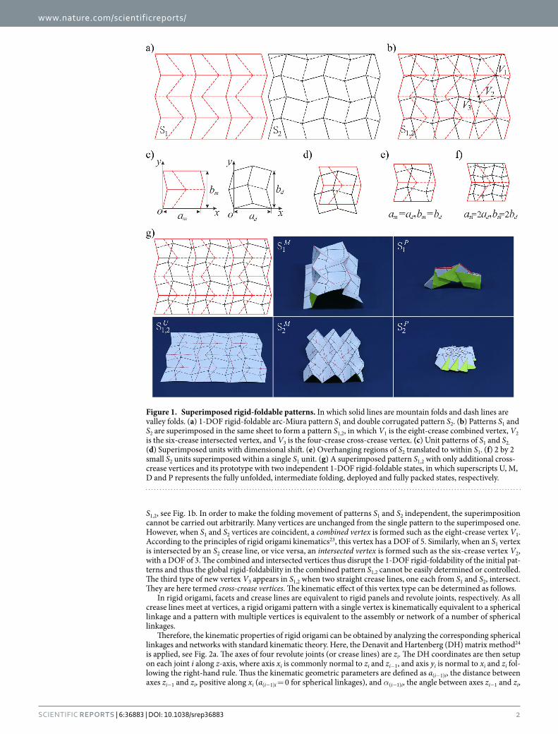
ResultsSuperimposed rigid-foldable patterns. Shown in Fig. 1a are two origami patterns. The red pattern, S1, forms a single-curved surface and the black one, S2, forms a planar surface, both with 1-DOF rigid-foldability. S1 and S2 crease patterns are superimposed on top of each other within the same sheet to form the crease pattern of
1School of Mechanical Engineering, Tianjin University, Tianjin 300072, China. 2School of Civil Engineering, University of Queensland, St Lucia, QLD 4072, Australia. 3Key Laboratory of Mechanism Theory and Equipment Design of Ministry of Education, Tianjin University, Tianjin 300072, China. Correspondence and requests for materials should be addressed to Y.C. (email: [email protected])
received: 24 July 2016
Accepted: 24 October 2016
Published: 10 November 2016
OPEN
www.nature.com/scientificreports/
2Scientific RepoRts | 6:36883 | DOI: 10.1038/srep36883
S1,2, see Fig. 1b. In order to make the folding movement of patterns S1 and S2 independent, the superimposition cannot be carried out arbitrarily. Many vertices are unchanged from the single pattern to the superimposed one. However, when S1 and S2 vertices are coincident, a combined vertex is formed such as the eight-crease vertex V1. According to the principles of rigid origami kinematics23, this vertex has a DOF of 5. Similarly, when an S1 vertex is intersected by an S2 crease line, or vice versa, an intersected vertex is formed such as the six-crease vertex V2, with a DOF of 3. The combined and intersected vertices thus disrupt the 1-DOF rigid-foldability of the initial pat-terns and thus the global rigid-foldability in the combined pattern S1,2 cannot be easily determined or controlled. The third type of new vertex V3 appears in S1,2 when two straight crease lines, one each from S1 and S2, intersect. They are here termed cross-crease vertices. The kinematic effect of this vertex type can be determined as follows.
In rigid origami, facets and crease lines are equivalent to rigid panels and revolute joints, respectively. As all crease lines meet at vertices, a rigid origami pattern with a single vertex is kinematically equivalent to a spherical linkage and a pattern with multiple vertices is equivalent to the assembly or network of a number of spherical linkages.
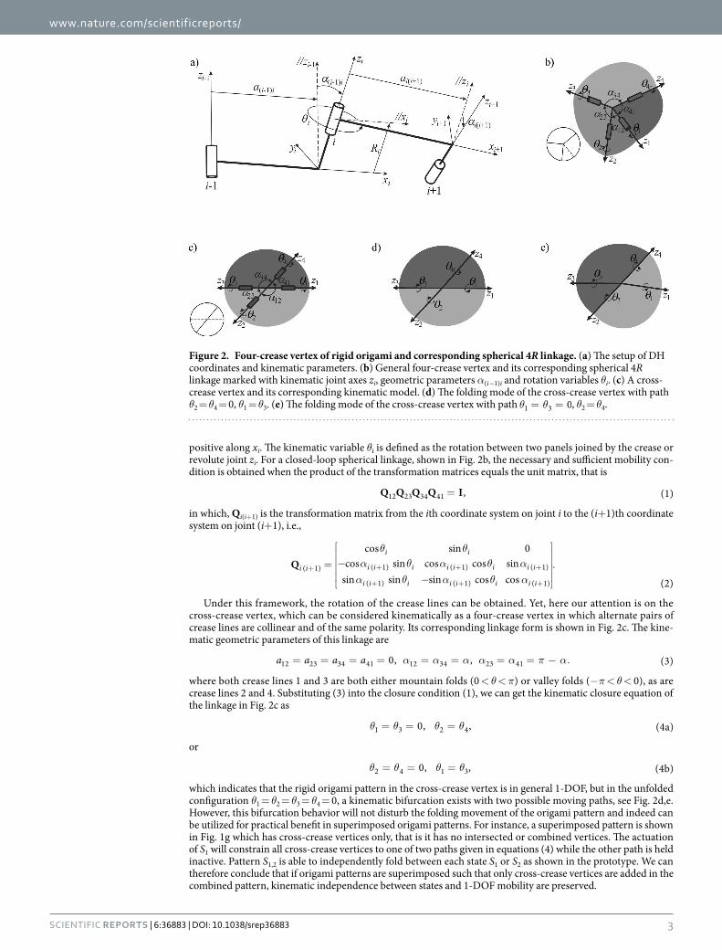
Therefore, the kinematic properties of rigid origami can be obtained by analyzing the corresponding spherical linkages and networks with standard kinematic theory. Here, the Denavit and Hartenberg (DH) matrix method24 is applied, see Fig. 2a. The axes of four revolute joints (or crease lines) are zi. The DH coordinates are then setup on each joint i along z-axis, where axis xi is commonly normal to zi and zi−1, and axis yi is normal to xi and zi fol-lowing the right-hand rule. Thus the kinematic geometric parameters are defined as a(i−1)i, the distance between axes zi−1 and zi, positive along xi (a(i−1)i = 0 for spherical linkages), and α(i−1)i, the angle between axes zi−1 and zi,
Figure 1. Superimposed rigid-foldable patterns. In which solid lines are mountain folds and dash lines are valley folds. (a) 1-DOF rigid-foldable arc-Miura pattern S1 and double corrugated pattern S2. (b) Patterns S1 and S2 are superimposed in the same sheet to form a pattern S1,2, in which V1 is the eight-crease combined vertex, V2 is the six-crease intersected vertex, and V3 is the four-crease cross-crease vertex. (c) Unit patterns of S1 and S2. (d) Superimposed units with dimensional shift. (e) Overhanging regions of S2 translated to within S1. (f) 2 by 2 small S2 units superimposed within a single S1 unit. (g) A superimposed pattern S1,2 with only additional cross-crease vertices and its prototype with two independent 1-DOF rigid-foldable states, in which superscripts U, M, D and P represents the fully unfolded, intermediate folding, deployed and fully packed states, respectively.
www.nature.com/scientificreports/
3Scientific RepoRts | 6:36883 | DOI: 10.1038/srep36883
positive along xi. The kinematic variable θi is defined as the rotation between two panels joined by the crease or revolute joint zi. For a closed-loop spherical linkage, shown in Fig. 2b, the necessary and sufficient mobility con-dition is obtained when the product of the transformation matrices equals the unit matrix, that is
=Q Q Q Q I, (1)12 23 34 41
in which, Qi(i+1) is the transformation matrix from the ith coordinate system on joint i to the (i+ 1)th coordinate system on joint (i+ 1), i.e.,
θ θα θ α θ αα θ α θ α
=
−
−
.+ + + +
+ + +
Qcos sin 0
cos sin cos cos sinsin sin sin cos cos (2)
i i
i i
i i i i i i i i
i i i i i i i i
( 1) ( 1) ( 1) ( 1)
( 1) ( 1) ( 1)
Under this framework, the rotation of the crease lines can be obtained. Yet, here our attention is on the cross-crease vertex, which can be considered kinematically as a four-crease vertex in which alternate pairs of crease lines are collinear and of the same polarity. Its corresponding linkage form is shown in Fig. 2c. The kine-matic geometric parameters of this linkage are
α α α α α π α= = = = = = = = − .a a a a 0, , (3)12 23 34 41 12 34 23 41
where both crease lines 1 and 3 are both either mountain folds (0 < θ < π) or valley folds (− π < θ < 0), as are crease lines 2 and 4. Substituting (3) into the closure condition (1), we can get the kinematic closure equation of the linkage in Fig. 2c as
θ θ θ θ= = =0, , (4a)1 3 2 4
or
θ θ θ θ= = =0, , (4b)2 4 1 3
which indicates that the rigid origami pattern in the cross-crease vertex is in general 1-DOF, but in the unfolded configuration θ1 = θ2 = θ3 = θ4 = 0, a kinematic bifurcation exists with two possible moving paths, see Fig. 2d,e. However, this bifurcation behavior will not disturb the folding movement of the origami pattern and indeed can be utilized for practical benefit in superimposed origami patterns. For instance, a superimposed pattern is shown in Fig. 1g which has cross-crease vertices only, that is it has no intersected or combined vertices. The actuation of S1 will constrain all cross-crease vertices to one of two paths given in equations (4) while the other path is held inactive. Pattern S1,2 is able to independently fold between each state S1 or S2 as shown in the prototype. We can therefore conclude that if origami patterns are superimposed such that only cross-crease vertices are added in the combined pattern, kinematic independence between states and 1-DOF mobility are preserved.
Figure 2. Four-crease vertex of rigid origami and corresponding spherical 4R linkage. (a) The setup of DH coordinates and kinematic parameters. (b) General four-crease vertex and its corresponding spherical 4R linkage marked with kinematic joint axes zi, geometric parameters α(i−1)i and rotation variables θi. (c) A cross-crease vertex and its corresponding kinematic model. (d) The folding mode of the cross-crease vertex with path θ2 = θ4 = 0, θ1 = θ3. (e) The folding mode of the cross-crease vertex with path θ θ= = 01 3 , θ2 = θ4.

www.nature.com/scientificreports/
4Scientific RepoRts | 6:36883 | DOI: 10.1038/srep36883
To ensure all new intersections in superimposed origami patterns are cross-crease vertices, we can consider the superimposition method of the pattern units. For the arc-Miura pattern, S1 in Fig. 1a, there are 2 by 3 units, one of which is shown as red in Fig. 1c with dimensions am and bm. For the double corrugated pattern, S2 in Fig. 1a, there are 2 by 2 units, one of which is shown as black in Fig. 1c with dimensions ad and bd. If units are superimposed as shown in Fig. 1d, it can easily be seen that no combined or intersected vertices are present in the superposed pattern and there are only cross crease vertices added. The overhanging regions of one state can be shifted in both directions to ensure there are no combined or intersected vertices generated when units are tessellated, shown in Fig. 1e. Then, if the dimensions of both units satisfy am = kad (or ad = kam) and bm = lbd, (or bd = lbm) where k and l are positive integers, tessellation of the superimposed units can be carried out to generate a larger origami pattern with only cross-crease vertices present. The examples k = l = 1 in Fig. 1e and k = l = 2 in Fig. 1f can both be tessellated into a larger origami pattern such as that given in Fig. 1g and SI Video 1.
Compact folding of non-flat-foldable structures. There are a very large number of 1-DOF rigid-foldable patterns that can be combined within a single sheet using the methods described above. Rather than simply combining known 1-DOF states, it is more useful to consider how secondary patterns can be com-bined with a primary pattern to develop applications with extended functionality. This is discussed in the context of specific examples as follows.
A 1-DOF distributed frame accordion shelter25 is shown in Fig. 3a, with nearly flat-folded frame elements sep-arated by spacer panels. In a deployed state S1
D, the frame elements give the shelter a high structural stiffness but prevent the shelter from reaching a compact packaged state. This is a critical weakness for a deployable structure, which are almost always required to be packaged for transport. A second pattern, the 1-DOF Miura-ori shown in Fig. 3b, has an in-plane folding motion that can never self-intersect during folding and reaches a compact flat-folded state S2
P with a cuboid volume boundary.Pattern superposition will allow the packaged configuration of S2 to resolve the packaging limitation of S1. One
such combination S1,2 is shown in Fig. 3c which has necessary conditions for independent 1-DOF rigid-foldability, that is only cross-crease vertices are introduced during pattern superposition. Design flexibility is introduced in the superimposed pattern that warrants further inspection. S1 is specified with seven independent control parameters: sector angle ϕ, side lengths a and b, spacer plate width wp, folded edge angle ηA, and number of tes-sellated units along x and y axes, M and N, respectively. S2 is similarly specified but without the spacer plate width parameter and so has six independent control parameters. Assuming S1 is the base pattern, design flexibility in specification of S2 is mostly preserved, with four of six parameters remaining free after the two tessellation unit length constraints are applied.
A full scale prototype of the crease pattern shown in Fig. 3c and SI Video 2 was constructed from a 2400 mm × 3600 mm × 3 mm extruded corrugated polypropylene sheet material. A 2 mm wide heated roller was used to compress the sheet along crease lines and the folded states were reached with manual folding by three people. As predicted by the kinematic analysis, the bifurcation in the unfolded state did not interrupt the folding motion of either state once the creases of a particular state were actuated. Good correspondence and independent foldability are seen between predicted and prototype folded forms at S1
D and S2P.
Transition to structural applications of origami geometry also necessitates the consideration of thick, rather than zero-thickness panels, with a comprehensive kinematic synthesis for rigid origami of thick panel presented in ref. 26. With a change from zero to non-zero sheet thickness, the physical polarity of crease lines is determined and so it is much easier to restore origami to a completely unfolded state and thus transition between states. A thick-panel multi-state accordion shelter was constructed as shown in Fig. 3d and SI Video 3, with the superim-posed crease pattern generated from methods described above. Similar to the zero-thickness case, cross-crease vertices in the thick-panel model are able to maintain 1-DOF mobility for each embedded pattern and the proto-type exhibits a smooth transition between both independent states.
Sequent folding of superimposed patterns. Although previous superimposed patterns can real-ize transformation between embedded patterns, it can be seen that all shown state transformations were via the unfolded configuration, that is the independent mobility followed the process of ‘fold S1 – unfold – fold S2’. However there exist certain special superimposed patterns that can directly transform between states, that is a ‘fold S1 – fold S2’ transformation that skips the unfolded configuration.
A superimposed pattern with square twist and Miura-ori embedded patterns can be obtained by following the superimposition process outlined previously. However, a modified process enables between-state transformation. A square twist pattern with sector angle θ and square length c is shown in Fig. 4a. It has a modified boundary condition with side lengths a and b, and sector angle ϕ, shown in black, such that when folded, its folded config-uration corresponds exactly with a Miura-ori pattern boundary, as shown in Fig. 4d. A Miura-ori pattern with sector angle ϕ, shown in red, can thus be superimposed onto the folded square twist configuration and subse-quently permit a second-stage of folding into the Miura-ori pattern. The between-state transformation enables a much more compact final package. The areal folding ratio of the first folding step being the folded state of square twist pattern is
γ θ ϕ θϕ
=− −a c b c
ab( 2 sin )( sin 2 sin )
sin,
(5)s
and that of Miura-ori pattern is

www.nature.com/scientificreports/
5Scientific RepoRts | 6:36883 | DOI: 10.1038/srep36883
γϕ θ ϕ θ
ϕ θ=
− + −−
.b c a c
b csin 2 sin sin2 ( 2 sin )
12( sin 2 sin ) (6)m
So the total areal folding ratio of superimposed pattern is
γθ ϕ θ ϕ θ
ϕ=
− − + −.+
a c b c a cab
( 2 sin )[ sin 2 sin sin2 ( 2 sin )]12 sin (7)s m
For the superimposed pattern in Fig. 4a, with θ = 45°, c = 27.0 mm, ϕ = 70°, a = 92.2 mm, b = 82.8 mm, the areal folding ratio of two folding steps is γs = 0.30 and γm = 0.16, respectively. And the total areal folding ratio γs+m is 0.05. Referring back to the superimposed unfolded state, additional Miura-ori pattern crease lines are created
Figure 3. Foldable origami shelter with two independent states. (a) The crease pattern S1 and the folded shelter configuration. (b) The Miura-ori pattern S2 and its packaged configuration. (c) Patterns S1 in black and S2 in red are superimposed to form a pattern S1,2, with independent rigid motion between the shelter state S1
D and the package state S2
P. (d) The thick-panel accordion shelter based on the superimposed Arc and Miura-ori patterns, with rigid motion between the two independent states.

www.nature.com/scientificreports/
6Scientific RepoRts | 6:36883 | DOI: 10.1038/srep36883
due to the projection of the Miura-ori pattern ‘through’ the folded square twist panels. A prototype of the super-imposed pattern and its full folding sequence are shown in Fig. 4d and SI Video 4.
Figure 4b shows a Miura-ori pattern, with sector angle ϕ and side lengths a and b, superimposed with a double corrugated unit, with sector angle β, parallelogram angle α and side lengths c and d. There are two permissible folding sequences, each of which ends with a fully folded Miura-ori, as shown in Fig. 4e and SI Video 5. The Miura-ori can be folded directly in a single step, or indirectly in two steps, with the first step being the folded state of the double corrugated pattern. For the indirect case, certain Miura-ori crease lines reverse their polarity in the second folding step, shown in blue, due to the overlap of crease lines in the double corrugated state. In order to
Figure 4. Sequent folding origami. (a) Superimposed pattern of square twist and Miura, with a modified boundary condition to permit between-state transformation. (b) Superimposed pattern of Miura-ori and double corrugated patterns. (c) Superimposed pattern of two square twist patterns. (d) Folding sequence of the pattern in (a). (e) Two folding sequences of the pattern in (b), with different final configurations. (f) Two folding sequences of the pattern in (c), with the same final configuration.

www.nature.com/scientificreports/
7Scientific RepoRts | 6:36883 | DOI: 10.1038/srep36883
ensure the overlap of crease lines in Miura-ori pattern after folding the double corrugated pattern, the crossed crease lines must be perpendicular to each other. The overlapped crease lines reduce the effective side length of the indirect Miura configuration and so the final packaged size is much smaller in the indirect case. The areal folding ratio of the direct case is
γ ϕ=+
.b a
b2 cos12 (8)m
i
and the areal folding ratio of the indirect case is
γβ β β ϕ
=− − + −
+a c b d a c
ab( 2 sin )[ 2 sin 2( 2 sin )cos ]
12, (9)d m
ii
with
γβ β
=− −a c b d
ab( 2 sin )( 2 sin )
dii
for the first double-corrugated folding step and
γβ β ϕ
β=− + −
−b d a c
b d2 sin 2( 2 sin )cos
12( 2 sin )mii
for the second Miura-ori folding step. For the superimposed pattern in Fig. 4b, with ϕ = 70°, a = 102.5 mm, b = 77.9 mm, α = 70°, β = 28°, c = 35.4 mm, d = 33.0 mm, the areal folding ratio of the first folding sequence is γ = .0 16m
i and the total areal folding ratio of the second folding sequence is γ = .+ 0 07d mii .
Finally, Fig. 4c shows a superimposed pattern with two embedded square twist patterns. Each square twist pattern has identical sector angle θ and square length c, but with different side length, a for black and 2a for red. It again has two permissible folding sequences, each of which has two steps, either folding the red square-twist pat-tern first then the black one second, or vice versa, as shown in Fig. 4f and SI Video 6. Unlike the previous example though, both sequences fold into the same final square, despite the folded configuration of the first folding step of two sequences being different. The total areal folding ratio of the first folding sequence is
γθ
=−
+a c
a( 3 sin ) ,
(10)r bi
2
2
with
γθ
=−a c
a( sin ) ,r
i2
2
γθθ
=−−
.a ca c
( 3 sin )( sin )b
i2
2
And the total areal folding ratio of the second folding sequence is
γθ
=−
+a c
a( 3 sin ) ,
(11)b rii
2
2
with
γθ
=−a c
a( 2 sin ) ,b
ii2
2
γθθ
=−−
.a ca c
( 3 sin )( 2 sin )r
ii2
2
For the superimposed pattern in Fig. 4c, with θ = 45°, a = 145.3 mm, c = 41.0 mm, the total areal folding ratio of the first folding sequence is γ = .+ 0 16r b
i , with γ = .0 64ri for the first folding step and γ = .0 25b
i for the second. The total areal folding ratio of the second sequence is also γ = .+ 0 16b r
ii , with γ = .0 36bii for the first folding step
and γ = .0 45rii for the second. The folding sequence is able to be determined by controlling the order with which
the blue crease lines fold, shown circled in Fig. 4f. For example, if the blue crease lines which are collinear with black lines remain collinear during the first folding step, then the black square twist pattern is folded first and the red twist pattern second, and vice versa.
DiscussionThe superimposition method presented in the paper combines two 1-DOF rigid-foldable origami patterns within one single sheet in such a way that only cross-crease vertices are generated. The particular kinematic proper-ties of cross-crease vertices mean that the folding of one motion path suppresses the other, and vice versa. The

www.nature.com/scientificreports/
8Scientific RepoRts | 6:36883 | DOI: 10.1038/srep36883
superimposed pattern with cross-crease vertices thus has preserved 1-DOF mobility and is able to fold inde-pendently between each embedded state. Sequent folding between origami patterns is also shown to be possible and enables folding between different states without the requirement of transition through an unfolded state.
The ability to have two or more independent objects coexistent within a single sheet enables many new types of self-folding and origami-inspired engineering design possibilities. States with complementary functionality can be combined to give a device extended performance capabilities, as was seen in the example of a non-flat foldable shelter embedded with a compact packaged state. States with radically different functionality can also be combined to create multi-tool sheets capable of performing a broad range of functions. Finally, as the super-position method is purely enabled by the special cross-crease vertex, the principles of thick-panel and 1-DOF rigid origami design remain applicable and so the method can be applied across a range of material types and application domains.
References1. Schenk, M., Viquerat, A. D., Seffen, K. A. & Guest, S. D. Review of inflatable booms for deployable space structures: packing and
rigidization. Journal of Spacecraft and Rockets 51, 762–778 (2014).2. Zirbel, S. A., Trease, B. P., Magleby, S. P. & Howell, L. L. Deployment methods for an origami-inspired rigid-foldable array. In
Proceedings of 42nd Aerospace Mechanisms Symposium (2014).3. Quaglia, C., Dascanio, A. & Thrall, A. Bascule shelters: A novel erection strategy for origami-inspired deployable structures.
Engineering Structures 75, 276–287 (2014).4. Gattas, J. & You, Z. Geometric assembly of rigid-foldable morphing sandwich structures. Engineering Structures 94, 149–159 (2015).5. Heimbs, S. Foldcore sandwich structures and their impact behaviour: an overview. In: Dynamic Failure of Composite and Sandwich
Structures, 491–544 (Springer, 2013).6. Sturm, R., Klett, Y., Kindervater, C. & Voggenreiter, H. Failure of CFRP airframe sandwich panels under crash-relevant loading
conditions. Composite Structures 112, 11–21 (2014).7. Schenk, M. & Guest, S. D. Geometry of miura-folded metamaterials. Proceedings of the National Academy of Sciences 110, 3276–3281
(2013).8. Silverberg, J. L. et al. Using origami design principles to fold reprogrammable mechanical metamaterials. Science 345, 647–650
(2014).9. Kuribayashi, K. et al. Self-deployable origami stent grafts as a biomedical application of ni-richtini shape memory alloy foil.
Materials Science and Engineering: A 419, 131–137 (2006).10. Funes-Huacca, M. et al. Portable self- contained cultures for phage and bacteria made of paper and tape. Lab on a Chip 12,
4269–4278 (2012).11. Song, J., Chen, Y. & Lu, G. Axial crushing of thin-walled structures with origami patterns. Thin-Walled Structures 54, 65–71 (2012).12. Ma, J. & You, Z. Energy absorption of thin-walled square tubes with a prefolded origami pattern, part i: Geometry and numerical
simulation. Journal of Applied Mechanics 81, 011003 (2014).13. You, Z. Folding structures out of plate materials. Science 345(6197), 623–645 (2014).14. Tachi, T. Simulation of rigid origami. Origami 4, 175–187 (2009).15. Wu, W. & You, Z. Modelling rigid origami with quaternions and dual quaternions. In Proceedings of the Royal Society of London A:
Mathematical, Physical and Engineering Sciences 466, 2155–2174 (2010).16. Abel, Z. et al. Rigid origami vertices: Conditions and forcing sets. arXiv preprint arXiv:1507.01644 (2015).17. Hull, T. Counting mountain-valley assignments for flat folds. Ars Combinatoria 67, 175–187 (2003).18. Miura, K. A note on intrinsic geometry of origami. In Proceedings of the 1st International Conference of Origami Science and
Technology Ferrara, Italy, 67, pp. 239–249 (December, 1991).19. Chen, Y., Feng, H., Ma, J., Peng, R. & You, Z. Symmetric waterbomb origami. Proceedings of the Royal Society A 472, 20150846
(2016).20. Sterman, Y., Demaine, E. D. & Oxman, N. PCB origami: A material-based design approach to computer-aided foldable electronic
devices. Journal of Mechanical Design 135, 114502 (2013).21. Peraza-Hernandez, E. A., Hartl, D. J., Malak, R. J. Jr & Lagoudas, D. C. Origami-inspired active structures: a synthesis and review.
Smart Materials and Structures 23, 094001 (2014).22. Hawkes, E. et al. Programmable matter by folding. Proceedings of the National Academy of Sciences 107, 12441–12445 (2010).23. Chiang, C. H. Kinematics of Spherical Mechanisms Krieger Pub. Co. (2000).24. Denavit, J. & Hartenberg, R. S. A kinematic notation for lower-pair mechanisms based on matrices. Trans. of the ASME. Journal of
Applied Mechanics 22, 215–221 (1955).25. Lee, T. U. & Gattas, J. M. Geometric design and construction of structurally-stabilised accordion shelters. Journal of Mechanisms and
Robotics 8(3) (2016).26. Chen, Y., Peng, R. & You, Z. Origami of thick panels. Science 349, 396–400 (2015).
AcknowledgementsY.C. would like to thank the financial support from the National Natural Science Foundation of China (Projects No. 51422506, No. 51275334 and No. 51290293) and the Ministry of Science and Technology of China (Project 2014DFA70710). J.M.G. is grateful for the support received from, the UQ Confucius Institute, the Australian Research Council under the Discovery Early Career Researcher funding scheme (DE160100289), and to undergraduate research students who assisted with construction of early prototypes.
Author ContributionsY.C. and J.M.G. proposed this research, supervised, and wrote the paper. X.L. carried out research, modelling, and prepared figures and Videos.
Additional InformationSupplementary information accompanies this paper at http://www.nature.com/srepCompeting financial interests: The authors declare no competing financial interests.How to cite this article: Liu, X. et al. One-DOF Superimposed Rigid Origami with Multiple States. Sci. Rep. 6, 36883; doi: 10.1038/srep36883 (2016).

www.nature.com/scientificreports/
9Scientific RepoRts | 6:36883 | DOI: 10.1038/srep36883
Publisher's note: Springer Nature remains neutral with regard to jurisdictional claims in published maps and institutional affiliations.
This work is licensed under a Creative Commons Attribution 4.0 International License. The images or other third party material in this article are included in the article’s Creative Commons license,
unless indicated otherwise in the credit line; if the material is not included under the Creative Commons license, users will need to obtain permission from the license holder to reproduce the material. To view a copy of this license, visit http://creativecommons.org/licenses/by/4.0/ © The Author(s) 2016