One-Dimensional Problemstaminmn/SME 3033 Finite Element Method/04-1D... · UNIAXIAL BAR ELEMENTS...
45
UNIAXIAL BAR ELEMENTS MNTamin, CSMLab One-Dimensional Problems
-
Upload
dinhkhuong -
Category
Documents
-
view
221 -
download
4
Transcript of One-Dimensional Problemstaminmn/SME 3033 Finite Element Method/04-1D... · UNIAXIAL BAR ELEMENTS...

UNIAXIAL BAR ELEMENTS
MNTamin, CSMLab
One-Dimensional Problems

UNIAXIAL BAR ELEMENTS
MNTamin, CSMLab
We wish to use FEM for solving the following problems:
d = 2 x 10⁻² mm
10 kN
x
x
Calculate displacement of
bar ABC, take E = 200GPa

UNIAXIAL BAR ELEMENTS
MNTamin, CSMLab
3-1 Objectives
1. To develop a system of linear equations for one-dimensional
problem.
2. To apply FE method for solving general problems involving
bar structures with different support conditions.
3-2 General Loading Condition
Consider a non-uniform bar subjected
to a general loading condition, as
shown.
Note: The bar is constrained by a fix support at
the top and is free at the other end. The positive
x-direction is taken downward.

UNIAXIAL BAR ELEMENTS
MNTamin, CSMLab
Types of Loading
a) Body force, f
Distributed force per unit volume (N/m3)
Example: self-weight due to gravity
b) Traction force, T
Force per unit area (N/m2)
For a 1-D problem,
area ofperimeter area
force
T
Examples: Frictional forces, Viscous drag,
and Surface shear.
c) Point load, Pi
Concentrated load (in Newton) acting at any point i.

UNIAXIAL BAR ELEMENTS
MNTamin, CSMLab
3-3 Finite element Modeling
3-3-1 Element Discretization
The first step is to subdivide the bar into several sections – a
process called discretization.
Note: The bar is discretized
into 4 sections, each has a
uniform cross-sectional area.
The non-uniform bar is
transformed into a stepped
bar.
We will use the stepped bar
as a basis for developing a
finite element model of the
original non-uniform bar.

UNIAXIAL BAR ELEMENTS
MNTamin, CSMLab
3-3-2 Numbering Scheme
To analyze the stepped bar systematically, a global numbering
scheme is assigned as shown. The x-direction is considered as
the global coordinate direction.
Note:
F1, …, F5 represent global
forces acting on the points
connecting all sections of the
stepped bar.
Q1, …, Q5 represent global
displacements of the points
resulting from the forces
acting on these points. TQQQQQQ 54321
TFFFFFF 54321The stepped bar is transformed into
a finite element model using 1-D
(line) elements.

UNIAXIAL BAR ELEMENTS
MNTamin, CSMLab
Connectivity between global and local nodes must be established for
each element, as tabulated in the table shown.
3-3-3 Element Connectivity
Element connectivity table
Consider a single line element. It lies in a local coordinate
system, denoted by x.
Note: Node number in local
coordinate is denoted by a
number with a hat on top.
q1 and q2 are nodal displacements
in the local coordinate direction.
^
^ ^ x̂
1̂ 2̂

UNIAXIAL BAR ELEMENTS
MNTamin, CSMLab
3-4-1 Natural Coordinate
3.4 Natural Coordinate and Shape Functions
We define a natural or intrinsic coordinate system, ,
1
21
12
xxxx
Note: The -coordinate will be used to define shape functions,
required to establish interpolation function for the displacement
field within the element.
Consider a single element. Local node 1 is at distance x1 from a
datum, and node 2 is at x2, measured from the same datum point.

UNIAXIAL BAR ELEMENTS
MNTamin, CSMLab
3-4-2 Shape Functions
We establish a linear interpolation function to represent the linear
displacement field within the element. To implement this, linear shape
functions are defined, given by,
2
1
2
121
ξξN
ξξN
and
The displacement field, u(x), within the element is not known.
For simplicity, it is assumed that the displacement varies
linearly from node 1 to node 2 within the element.

UNIAXIAL BAR ELEMENTS
MNTamin, CSMLab
The linear displacement field, u(x), within the element can now
be expressed in terms of the linear shape functions and the
local nodal displacement q1 and q2 as:
21
^
2211
^
2
1
2
1)(
)(
qqxu
qNqNxu
In matrix form:
qN)x(u^
where 21 NNN
and Tqqq
qq 21
2
1

UNIAXIAL BAR ELEMENTS
MNTamin, CSMLab
Coordinate x of any point on the element (measured from the
same datum point as x1 and x2) can be expressed in terms of
the same shape functions, N1 and N2 as
3-4-3 Isoparametric Formulation
21
2211
2
1
2
1xxx
xNxNx
When the same shape functions N1 and N2 are used to establish
interpolation function for coordinate of a point within an element and
the displacement of that point, the formulation is specifically referred
to as an isoparametric formulation.

UNIAXIAL BAR ELEMENTS
MNTamin, CSMLab
Example 2-1
(a)Evaluate , N1, and N2 at point P.
(b) If q1 = 0.003 in and q2 = -0.005 in, determine the value of
displacement u at point P.
Solution
(a) The coordinate of point P is given by
1
2 1
21
224 20 1
36 20
0.5
P
P
x xx x

UNIAXIAL BAR ELEMENTS
MNTamin, CSMLab
1
2
1 1 0.50.75
2 2
1 1 0.50.25
2 2
N
N
(b) Displacement of point P
1 1 2 2
0.75 0.003 0.25 0.005
0.001 in
P
P
u N q N q
u
The shape functions are:

UNIAXIAL BAR ELEMENTS
MNTamin, CSMLab
3-5 Strain-Displacement Relation
Normal strain is related to displacement by
du
dx
Using the chain rule of differentiation
du d
d dx
1
2 1 2 1
2 21
dx x
x x dx x x
1 2
1 2
1 1
2 2 2
q qduu q q
d
The two terms of the above relation are obtained as follows

UNIAXIAL BAR ELEMENTS
MNTamin, CSMLab
which can be written in matrix form as
2
1
q
qB
where [B] is a row matrix called the strain-displacement matrix,
given by
2 1
1 11 1 1 1
e
Bx x l
since x2 – x1 = element length = le.
Thus the normal strain relation can be written as
1 2
2 1
1q q
x x

UNIAXIAL BAR ELEMENTS
MNTamin, CSMLab
3-6 Stress-Strain Relation
1
2
qE B
q
Normal stress is related to the normal strain by a Hooke’s
law, E
where E is modulus of elasticity.
Substitute for the normal strain ,
we get,
Robert Hooke (1635-1703);
(Experimental Philosopher)

UNIAXIAL BAR ELEMENTS
Theory of Minimum Potential Energy
17

UNIAXIAL BAR ELEMENTS
MNTamin, CSMLab
3-7 Element Stiffness Matrix
We will use the potential energy approach to derive the
element stiffness matrix [k] for the 1-D element.
p U
For the non-uniform bar, its total potential energy is given by
1
2
T T T
p i iL L L
i
A dx u fA dx u T dx Q P
U = internal strain energy;
= potential energy of external forces.
Total potential energy of a body subjected to loads is given by,
Since the bar has been discretized into finite elements
1
2
T T T
p i ie e e
e e e i
A dx u fA dx u T dx Q P

UNIAXIAL BAR ELEMENTS
MNTamin, CSMLab
We will derive the element stiffness matrix of the 1-D element
using the internal strain energy term, U as follows,
1
2
T
ee
U A dx
E B q
Recall, the stress and strain are given by
and B q
Substitute these into the expression for Ue,
1
2
1
2
1
2
T
ee
T T
e
T T
ee
U E B q B q A dx
q B E B q A dx
U q B E B A dx q

UNIAXIAL BAR ELEMENTS
MNTamin, CSMLab
2
2
e
e
lddx d
dx l
Substitute and simplifying the expression yields,
1
1
2
1
2 2
12
2 2
11 1 11 1
12
11 11 1
12
1 11
1 12
T T ee e e
T T ee e
T
e e e
e e
T
e e e
e
T e ee
e
lU q B E B A d q
lq B E B A q
q A l E ql l
q A l E ql
A EU q q
l
Recall again,

UNIAXIAL BAR ELEMENTS
MNTamin, CSMLab
The internal strain energy for the 1-D element can now be
written in the form,
1
2
T e
eU q k q
where [k]e represents the element stiffness matrix for the 1-D
element, i.e.
1 1
1 1
e e e
e
E Ak
l
Note: Ee = elastic modulus;
Ae = cross-sectional area;
le = element length.

UNIAXIAL BAR ELEMENTS
MNTamin, CSMLab
3-8 Element Force Vector
a) Due to body force, fb
The potential energy due to body force fb in a single element is
given by the second term, i.e.
1 1 2 2
1 1 2 2
T
f be
T
be
T
f e be
u f A dx
N q N q f A dx
A f N q N q dx
The forces acting on 1-D structures can be of body force, fb,
traction force, T, and concentrated force, P. They may act
individually in various combination.
1
2
T T T
p b i ie e e
e e e i
A dx u f A dx u T dx Q P
The total potential energy of the structure,

UNIAXIAL BAR ELEMENTS
MNTamin, CSMLab
1
2
e bT e
f
e be
A f N dxq
A f N dx
1
11
1
21
1
2 2 2
1
2 2 2
e e
e
e e
e
l lN dx d
l lN dx d
Recall that,
2
eldx d
12
12
2
e b e
T T e e bf
e b e
A f l
A l fq q
A f l
Rewrite,
Substitute and simplifying, yields
Also, - Show details of
this integration.

UNIAXIAL BAR ELEMENTS
MNTamin, CSMLab
The potential energy due to the body force can now be
expressed in the form,
T e
f q f
where the force vector due to body force fb is,
1
12
e e e bA l ff
Quiz: Can you give the physical interpretation of {f}e?
UNIAXIAL BAR ELEMENTS
MNTamin, CSMLab
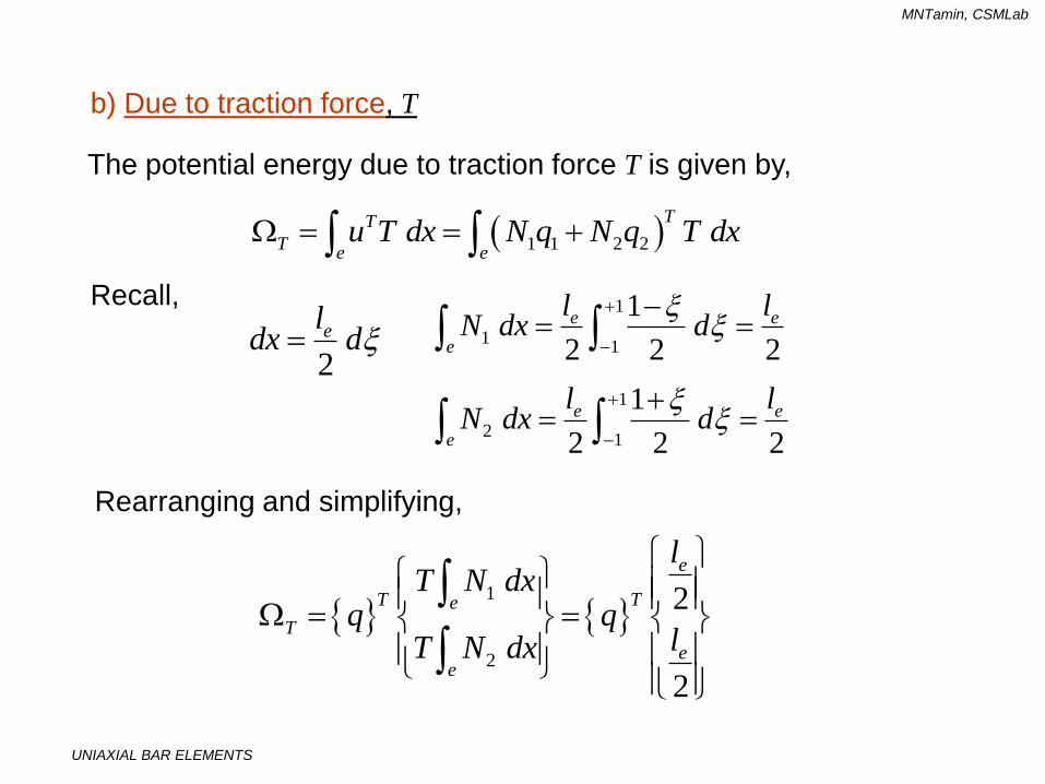
b) Due to traction force, T
The potential energy due to traction force T is given by,
1 1 2 2
TT
Te eu T dx N q N q T dx
Rearranging and simplifying,
1
2
2
2
e
T Te
T
ee
lT N dx
q qlT N dx
1
11
1
21
1
2 2 2
1
2 2 2
e e
e
e e
e
l lN dx d
l lN dx d
2
eldx d
Recall,

UNIAXIAL BAR ELEMENTS
MNTamin, CSMLab
The last equation is in the form,
1
12
T eT
lq T
i.e.
T e
T q T
Thus, element traction force vector due to traction T,
1
12
e eTlT
Quiz: Can you give the physical interpretation of this?

UNIAXIAL BAR ELEMENTS
MNTamin, CSMLab
Summary
1 1
1 1
e e e
e
A Ek
l
3. Element force vector
due to body force, fb
1
12
e e e bA l ff
4. Element force vector
due to traction force, T
1
12
e eTlT
1
2
1 1e
qE
ql
We have established, for 1-D problems,
1. Stress-strain relation
2. Element stiffness matrix

UNIAXIAL BAR ELEMENTS
MNTamin, CSMLab
Example 3-2
A thin steel plate has a uniform thickness t = 1 in., as shown. Its elastic modulus, E = 30 x 106 psi, and weight density, r = 0.2836 lb/in3.
The plate is subjected to a point load P = 100 lb at its midpoint and a traction force T = 36 lb/ft.
Determine:
a) Displacements at the mid-point and at the free end,
b) Normal stresses in the plate, and
c) Reaction force at the support.

UNIAXIAL BAR ELEMENTS
MNTamin, CSMLab
Solution
1. Transform the given plate into 2 sections, each having
uniform cross-sectional area.
Area at midpoint is
Amid = 4.5 in2.
Average area of section 1 is
A1 = (6 + 4.5)/2 = 5.25 in2.
Average area of section 2 is
A2 = (4.5 + 3)/2 = 3.75 in2.
2. Model each section using 1-D
(line) element.
Note:

UNIAXIAL BAR ELEMENTS
MNTamin, CSMLab
element 2: 6
(2) 1 13.75 30 10
1 112k
4. Assemble global stiffness matrix,
6
5.25 5.25 030 10
5.25 9.00 3.7512
0 3.75 3.75
K
3. Write the element stiffness matrix for each element
element 1: 6
(1) 1 15.25 30 10
1 112k
Note: The main diagonal must contain positive numbers only!

UNIAXIAL BAR ELEMENTS
MNTamin, CSMLab
5. Write the element force vector for each element
a) Due to body force, fb = 0.2836 lb/in3
element 1 (1) 15.25 12 0.2836
12bf
element 2 (2) 13.75 12 0.2836
12bf
Assemble global force vector due to body force,
5.25 8.912 0.2836
9.00 15.32
3.75 6.4
bF
UNIAXIAL BAR ELEMENTS
MNTamin, CSMLab
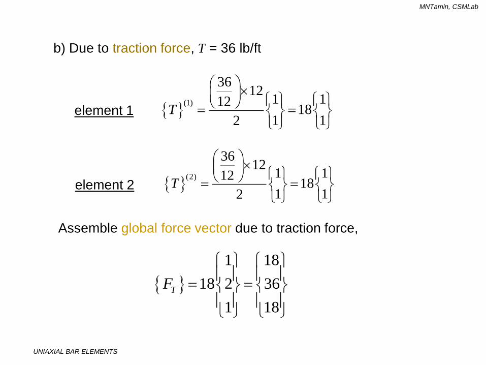
b) Due to traction force, T = 36 lb/ft
element 1 (1)
3612
1 11218
1 12T
element 2 (2)
3612
1 11218
1 12T
Assemble global force vector due to traction force,
1 18
18 2 36
1 18
TF

UNIAXIAL BAR ELEMENTS
MNTamin, CSMLab
c) Due to concentrated load, P = 100 lb at node 2
0
100
0
PF
6. Assemble all element force vectors to form the global force
vector for the entire structure.
8.9 18 0 26.9
15.3 36 100 151.3
6.4 18 0 24.4
F lb

UNIAXIAL BAR ELEMENTS
MNTamin, CSMLab
7. Write system of linear equations (SLEs) for entire model
K Q F
16
2
3
5.25 5.25 0 26.930 10
5.25 9.00 3.75 151.312
0 3.75 3.75 24.4
Q
Q
Q
The SLEs can be written in condensed matrix form as
Expanding all terms and substituting values, we get
Note:
1. The global force term includes the unknown reaction force R1 at
the support. But it is ignored for now.
2. The SLEs have no solutions since the determinant of [K] = 0;
Physically, the structure moves around as a rigid body.

UNIAXIAL BAR ELEMENTS
MNTamin, CSMLab
8. Impose boundary conditions (BCs) on the global SLEs
There are 2 types of BCs:
a) Homogeneous = specified zero displacement;
b) Non-homogeneous = specified non-zero displacement.
In this example, homogeneous BC exists at node 1. How to
impose this BC on the global SLEs?
DELETE ROW AND COLUMN #1 OF THE SLEs!
16
2
3
5.25 5.25 0 26.930 10
5.25 9.00 3.75 151.312
0 3.75 3.75 24.4
Q
Q
Q

UNIAXIAL BAR ELEMENTS
MNTamin, CSMLab
62
3
9.00 3.75 151.330 10
3.75 3.75 24.412
Q
Q
Solve using Gaussian elimination method, yields
52
53
1.339 10
1.599 10
Qin
Q
9. Solve the reduced SLEs for the unknown nodal
displacements
The reduced SLEs are,
Quiz: Does the answers make sense? Explain…

UNIAXIAL BAR ELEMENTS
MNTamin, CSMLab
10. Estimate stresses in each elements
1( )
2
11 1e
e
qE B q E
ql
element 1
1 6
5
0130 10 1 1 33.48 psi
1.339 1012
element 2
5
2 6
5
1.339 10130 10 1 1 6.5 psi
12 1.599 10
Recall,

UNIAXIAL BAR ELEMENTS
MNTamin, CSMLab
11. Compute the reaction force R1 at node 1
165
5
5.25 5.25 0 0 26.930 10
5.25 9.00 3.75 1.339 10 151.312
0 3.75 3.75 1.599 10 24.4
R
6
5
1
5
030 10
5.25 5.25 0 1.339 10 26.933412
1.599 10
R
1 202.68 lbR
We now include the reaction force term in the global SLEs.
From the 1st. equation we get,
We have,

UNIAXIAL BAR ELEMENTS
MNTamin, CSMLab
Example 3-3
A concentrated load P = 60 kN is applied at the midpoint of a uniform bar as shown.
Initially, a gap of 1.2 mm exists between the right end of the bar and the support there.
If the elastic modulus E = 20 x 103 N/mm2, determine the:
a) displacements field,
b) stresses in the bar, and
c) reaction force at the support.
P
150 mm 150 mm
1.2 mm
x
250 mm2

UNIAXIAL BAR ELEMENTS
MNTamin, CSMLab
Solution
1. Write the element stiffness matrices and assemble the
global stiffness matrix.
3
1 1 020 10 250
1 2 1150
0 1 1
K
2. Write the element force vectors and assemble the global force
vector.
30, 60 10 , 0T
F
3. Write the global system of linear equations.
133
2
3
500 500 0 010
500 1000 500 10 6015
0 500 500 0
Q
Q
Q

UNIAXIAL BAR ELEMENTS
MNTamin, CSMLab
4. Impose the boundary conditions.
We have; Q1 = 0; Q3 = 1.2 mm. Using Gaussian elimination
method:
a) Delete 1st row and column.
b) Delete 3rd row and column and modify the force term.
133
2
500 500 0 010
500 1000 500 10 6015
0 500 500 1.2 0
Q
Q
The reduced SLE becomes,
3
3
2
500 1.2101000 10 60
15 15Q
Modification to
force term

UNIAXIAL BAR ELEMENTS
MNTamin, CSMLab
7. Solve the reduced SLE, we get
8. Compute stresses in the bar,
2 1.5 mmQ
3
1
1
0120 10 1 1
1.5150
200 MPa
3
2
2
1.5120 10 1 1
1.2150
40 MPa
9. Compute reaction forces at supports
Using the 1st and 3rd equations, we obtain,
R1 = -50 x 103 N; R3 = -10 x 103 N.

UNIAXIAL BAR ELEMENTS
MNTamin, CSMLab
Exercise 2-1
A composite bar ABC is subjected to axial forces as shown. Given, the elastic moduli, E1 = 200 GPa and E2 = 70 GPa. Estimate:
a) Displacement of end C; [Answer: dC = 6.62x10⁻² mm]
b) Stress in section 2, and
c) Reaction force at support A.
Verify your results with analytical solution.

UNIAXIAL BAR ELEMENTS
MNTamin, CSMLab
Exercise 2-2
Reconsider Exercise 2-1. Suppose a gap of d = 2 x 10⁻² mm exists between end C and a fixed support there. Estimate:
a) Displacement of point B;
b) Stress in section 1, and
c) Reaction forces at both supports.
2 x 10⁻² mm
10 kN

UNIAXIAL BAR ELEMENTS
MNTamin, CSMLab
Assignment 2-1
Find a journal paper on the application of finite element method to model and simulate real world problems, from various journals on the internet. (e.g. : www.sciencedirect.com).
Download the paper (in PDF format), and print it.
Read the paper and make one (1) page summary on the content of the paper - typewritten.
Submit the summary and copy of the paper to me. Use cover page.
Due in: 7 days time.