On XFEM applications to dislocations and interfaces2007b Gracie) On XFEM... · On XFEM applications...
18
On XFEM applications to dislocations and interfaces Ted Belytschko * ,1 , Robert Gracie Department of Mechanical Engineering, Northwestern University, 2145 Sheridan Road, Evanston, IL 60208-3111, USA Received 15 October 2006; received in final revised form 10 February 2007 Dedicated to Dusan Krajcinovic, whose work in damage mechanics and plasticity was illuminating and invaluable to the mechanics community. Abstract A method for modelling dislocations in systems with arbitrary materials interfaces is described. The method is based on the extended finite element method (XFEM) where dislocations are mod- elled in the manner of the Volterra dislocation model. A method for calculating the Peach–Koehler force by J-integrals in this framework is studied. The method is compared to closed form solutions for interface problems and excellent accuracy is obtained. The convergence and accuracy of the method is studied in two problems where analytical solutions are available: an edge dislocation inter- acting with a free-surface and an edge dislocation interacting with a bimaterial interface. The appli- cability of the method to more complicated problems is illustrated by the modelling of slip misorientation of an edge dislocation with a glide plane intersecting a material interface and dislo- cations in a multi-material domain with non-parallel interfaces. Ó 2007 Published by Elsevier Ltd. Keywords: Dislocations; Interfaces; Extended finite element method; Peach–Koehler force 1. Introduction Computational Dislocation Dynamics (DD) is increasingly being applied to the resolution of important questions in nonlinear bulk material behaviour and plasticity, 0749-6419/$ - see front matter Ó 2007 Published by Elsevier Ltd. doi:10.1016/j.ijplas.2007.03.003 * Corresponding author. E-mail address: [email protected] (T. Belytschko). 1 Walter P. Murphy and McCormick Professor of Mechanical Engineering. International Journal of Plasticity xxx (2007) xxx–xxx www.elsevier.com/locate/ijplas ARTICLE IN PRESS Please cite this article in press as: Belytschko, T., Gracie, R., On XFEM applications to disloca- tions..., Int. J. Plasticity (2007), doi:10.1016/j.ijplas.2007.03.003
Transcript of On XFEM applications to dislocations and interfaces2007b Gracie) On XFEM... · On XFEM applications...

ARTICLE IN PRESS
International Journal of Plasticity xxx (2007) xxx–xxx
www.elsevier.com/locate/ijplas
On XFEM applications to dislocationsand interfaces
Ted Belytschko *,1, Robert Gracie
Department of Mechanical Engineering, Northwestern University, 2145 Sheridan Road,
Evanston, IL 60208-3111, USA
Received 15 October 2006; received in final revised form 10 February 2007
Dedicated to Dusan Krajcinovic, whose work in damage mechanics and plasticity was illuminating andinvaluable to the mechanics community.
Abstract
A method for modelling dislocations in systems with arbitrary materials interfaces is described.The method is based on the extended finite element method (XFEM) where dislocations are mod-elled in the manner of the Volterra dislocation model. A method for calculating the Peach–Koehlerforce by J-integrals in this framework is studied. The method is compared to closed form solutionsfor interface problems and excellent accuracy is obtained. The convergence and accuracy of themethod is studied in two problems where analytical solutions are available: an edge dislocation inter-acting with a free-surface and an edge dislocation interacting with a bimaterial interface. The appli-cability of the method to more complicated problems is illustrated by the modelling of slipmisorientation of an edge dislocation with a glide plane intersecting a material interface and dislo-cations in a multi-material domain with non-parallel interfaces.� 2007 Published by Elsevier Ltd.
Keywords: Dislocations; Interfaces; Extended finite element method; Peach–Koehler force
1. Introduction
Computational Dislocation Dynamics (DD) is increasingly being applied to theresolution of important questions in nonlinear bulk material behaviour and plasticity,
0749-6419/$ - see front matter � 2007 Published by Elsevier Ltd.
doi:10.1016/j.ijplas.2007.03.003
* Corresponding author.E-mail address: [email protected] (T. Belytschko).
1 Walter P. Murphy and McCormick Professor of Mechanical Engineering.
Please cite this article in press as: Belytschko, T., Gracie, R., On XFEM applications to disloca-tions..., Int. J. Plasticity (2007), doi:10.1016/j.ijplas.2007.03.003

2 T. Belytschko, R. Gracie / International Journal of Plasticity xxx (2007) xxx–xxx
ARTICLE IN PRESS
e.g. Amodeo and Ghoniem (1990), Canova et al. (1993), Van der Giessen and Needleman(1995), Zbib et al. (1998), Ghoniem et al. (2000), Shehadeh et al. (2005). Of interest morerecently are applications involving micro/nano scale systems. For example, Polonsky andKeer (1996) used DD to model plasticity due to contact in micro-scale systems; Nicolaet al. (2005) have computationally reproduced size effects in thin films; Balint et al.(2006) have studied size effects in crystals and polycrystals; Espinosa et al. (2006) haveshown size effects in freestanding FCC films and partially calibrated them by experiments.Usually, these computational methods are based on superposition of infinite domain ana-lytical solutions. For micro/nano scale systems, the effects of boundaries, material inter-faces and material anisotropy are important; however, the extension of existing methodsto these problems is difficult, since the existence of Green’s function for specific geometriesis limited, see Ghoniem and Han (2005).
Alternative methods are the phase field method (PFM) of Wang et al. (2001) and thelevel set based method of Xiang et al. (2003). The PFM, like the proposed method, directlymodels the displacement field but represents the discontinuities of the dislocations by reg-ularizations. Both methods have been applied with fast Fourier transforms, though inprinciple they can be applied with standard finite elements. Another method which directlyapproximates the displacement field due to the dislocations is that of Lemarchand et al.(2001), where the effect of the dislocations in the continuum is introduced through a plasticstrain.
In DD a sequence of equilibrium solutions must be obtained with evolving dislocations;at each step the total stress of the domain is determined for a given distribution, numberand geometry of the dislocations. The geometry, number and location of the dislocationsfor the next step of the simulation are determined using a phenomenological equation ofmotion for each dislocation, where the Peach–Koehler force is the driving force, and a setof rules, which govern among other things, dislocation nucleation and annihilation.
The DD codes based on superposition determine the total stress of the domain by thesum of the analytical solutions of dislocations in an infinite domain plus an image stressfield. In three-dimensional methods, these solutions usually take the form of Green’s func-tions. Methods based on superposition are difficult to extend to important problems suchas anisotropic materials and material interfaces. With the exception of a few geometries,such as the recently developed Green’s functions of Ghoniem and Han (2005) and Hanand Ghoniem (2005) for parallel anisotropic materials, Green’s functions cannot readilybe obtained for anisotropic materials with arbitrary material interfaces. Therefore, meth-ods based on Green’s functions for these applications will be difficult to develop.
We describe some studies with a method we have recently developed (Gracie et al.,2007), that is easily able to treat anisotropic materials, interfaces and grain boundaries.The methodology is based on the extended finite element method (Belytschko and Black,1999; Moes et al., 1999; Belytschko et al., 2001), in which an arbitrary discontinuity isadded to a finite element solution independent of the mesh, i.e. the discontinuity doesnot need to conform to the mesh in any way. This enables the method to model a dislo-cation as described originally by Volterra (1907): an interior discontinuity that resultsfrom cutting a solid, displacing the two opposing surfaces and then regluing the solidalong the cut. The stresses that are computed by an XFEM calculation correspond tothose that would result from this process. The work of Ventura et al. (2005) which pro-posed a dislocation model based on a similar finite element method, the Partition of UnityMethod, was particularly influential to the current work.
Please cite this article in press as: Belytschko, T., Gracie, R., On XFEM applications to disloca-tions..., Int. J. Plasticity (2007), doi:10.1016/j.ijplas.2007.03.003

T. Belytschko, R. Gracie / International Journal of Plasticity xxx (2007) xxx–xxx 3
ARTICLE IN PRESS
To account for finite domain boundary conditions, superposition methods requirethe computation of an image field. In Fivel et al. (1996), the image stress is determinedby a method based on the Boussinesq problem, while in the method of Van der Gies-sen and Needleman (1995) it is computed by the finite element method. In contrast, themethod presented here uses a finite element method (FEM) to compute the total stressfield.
Here we examine the suitability of the J-Integral for computing the Peach–Koehlerforce. Since the method presented here does not use superposition, the self-stress of a dis-location cannot simply be subtracted out of the total stress. So the Peach–Koehler for-mula, (Peach and Koehler, 1950), cannot be applied. We show that the J-Integral iseffective for computing the Peach–Koehler force and discuss its relative advantages anddisadvantages.
From the examples considered here, the extension of the method to anisotropic mate-rials and grain boundaries will become apparent. The ability of the method to easily modelproblems involving interfaces is one of its principal advantages. Here, we will illustrate theeffectiveness of the method for problems involving interfaces, albeit in some rather simpleproblems.
In the following section, we summarize the methodology and the discrete equations ofthe proposed method. In Section 3 we discuss the computation of the Peach–Koehler forceby the J-integral. In Section 4 we apply the proposed method to problems involving inter-faces and in Section 5 we present the conclusions.
2. Methodology
We first briefly review the method for modelling dislocations. Consider the domain Xbounded by C with tractions t defined on boundary Ct, displacements �u defined on bound-ary Cu and with internal surfaces of discontinuity a, a ¼ 1 to nD, that model the nD dislo-cations Ca
d . We define Cd ¼S
aCad . While the method is applicable to any type of
dislocation, we restrict this paper to edge dislocations.The geometry of dislocation a is described by an affine function of the coordinates,
f aðxÞ ¼ 0, where
f aðxÞ ¼ a0 þ ajxj ð1Þand repeated indices denote summations. The core is described by the intersection of theglide plane, f aðxÞ ¼ 0, and a distance function (or level set function) gaðxÞ ¼ 0 wheregaðxÞ > 0 on the active portion of the slip plane.
Let S be the set of all nodes, Ea be the set of all elements cut by discontinuity a andSa be the set of enriched nodes for dislocation a; the latter is the set of all nodes ofelements in Ea. A virtual element is superimposed on the element containing the dislo-cation core, as shown in Fig. 1, so that the corner node is coincident with the center ofthe core. The core node of dislocation a is denoted by Ca and Ca 2 Sa. The displace-ment approximation for the continuum containing nD dislocations with Burger’s vectorsba has the form
uðx; tÞ ¼XI2S
NðxÞI uIðtÞ þXnD
a¼1
baXJ2Sa
eN J ðxÞWaJ ðx; tÞ ð2Þ
Please cite this article in press as: Belytschko, T., Gracie, R., On XFEM applications to disloca-tions..., Int. J. Plasticity (2007), doi:10.1016/j.ijplas.2007.03.003

Fig. 1. Illustration of the virtual element, the cross-hatched triangle, which is superimposed on the finite elementmesh. The dashed line represents the glide plane. Grey circles represent nodes in the set Sa.
4 T. Belytschko, R. Gracie / International Journal of Plasticity xxx (2007) xxx–xxx
ARTICLE IN PRESS
where NI and eN J are standard finite element shape functions and uI are the nodal displace-ments. For elements cut by the discontinuities eN I ¼ NI , except in the element containingthe core where eN I are the shape functions of the superimposed element.
The function WaI ðx; tÞ is called the enrichment and introduces the interior discontinuities
into the displacement field. We will consider two forms of the enrichment:
1. regularized and compatible
WaI ðx; tÞ ¼ ðHðf aðx; tÞÞ � Hðf aðxI ; tÞÞÞHðgaðx; tÞÞ ð3Þ
2. incompatible
WaI ðx; tÞ ¼ ðHðf aðx; tÞÞ � Hðf aðxI ; tÞÞ þ Hðf aðxI ; tÞÞdICaÞHðgaðx; tÞÞ ð4Þ
where Hð�Þ is the Heaviside function given by
HðzÞ ¼0; z < 0
1; z P 0:
�ð5Þ
and dIJ is the Kronecker delta. The first enrichment was previously proposed in Gracieet al. (2007); the second enrichment is a new representation. As indicated by the names,the first enrichment is a regularization of the classical Volterra dislocation field. Theshapes of the enrichment functions along the dislocation line are shown in Fig. 2; the clas-sical dislocation model has the shape shown in Fig. 2a.
Eq. (3) employs a linear regularization of the core, Fig. 2b. The linear regularization ismesh dependent; as the approximation is refined, the linear regularization will converge tothe classical solution, shown in Fig. 2a. As a result, the total energy of the approximationdiverges as the mesh is refined; however, the Peach–Koehler force acting on a dislocationconverges. If the total energy is not of interest, and only the movement of dislocations,which is governed by the Peach–Koehler force, then the core behaviour shown in Figs.2a and 2b can be used as an approximation to the actual dislocation core. When suchapproximations are too limiting, more accurate core displacement models such as thePeierls–Nabarro model (Peierls, 1940; Nabarro, 1947), can be introduced through the
Please cite this article in press as: Belytschko, T., Gracie, R., On XFEM applications to disloca-tions..., Int. J. Plasticity (2007), doi:10.1016/j.ijplas.2007.03.003

Fig. 2. Illustration of the tangential jump, ut, along the glide plane from (a) the infinite domain analyticalsolution for an edge dislocation and the incompatible enrichment (4) and (b) the regularized and compatibleenrichment (3).
T. Belytschko, R. Gracie / International Journal of Plasticity xxx (2007) xxx–xxx 5
ARTICLE IN PRESS
enrichment of the displacement approximation (2). However, the Peach–Koehler forceand the energy outside a core region is almost independent of the regularization.
2.1. Discrete equations
The weak form of the equilibrium equation is the standard principle of virtual work:find u 2 U, such thatZ
X=Cd
�ðvÞT : rð�ðuÞÞdX�Z
Xg � vdX�
ZCt
t � vdC ¼ 0; v 2 U0 ð6Þ
where
U0 ¼ fu 2 H 1ðX=CdÞ; u ¼ 0 on Cug ð7ÞU ¼ fu 2 H 1ðX=CdÞ; u ¼ �u on Cug ð8Þ
where r is the Cauchy stress and g is the body force per unit volume. Note that the dis-continuities Cd are omitted from X.
A small strain, linear elastic formulation will be adopted, although the approach caneasily be extended to large strain and material nonlinearities. The strain displacement rela-tion is
� ¼ symru ð9Þand the constitutive equations is
r ¼ C : � ð10ÞWe place no restriction on C; it may be for either an isotropic or an anisotropic material.
Substituting the approximation (2) into the weak form of the equilibrium Eq. (6) thediscrete equations to be solved are
Kuudþ Kubb ¼ fext ð11Þwhere d ¼ fu1; u2; . . . ; unng are the nodal displacement degrees of freedom of the nn nodes,and bT ¼ fkb1k; kb2k; . . . ; kbndkg is a matrix of Burgers vector magnitudes. The submatri-ces Kuu and Kub and the matrix f ext are given by
KuuIJ ¼
ZX
BTI CBJ dX ð12Þ
KubIa ¼
ZX
BTI CDa dX ð13Þ
Please cite this article in press as: Belytschko, T., Gracie, R., On XFEM applications to disloca-tions..., Int. J. Plasticity (2007), doi:10.1016/j.ijplas.2007.03.003

6 T. Belytschko, R. Gracie / International Journal of Plasticity xxx (2007) xxx–xxx
ARTICLE IN PRESS
fext ¼Z
XNTgdXþ
ZCt
NTtdC ð14Þ
for I ; J 2S, and
BI ¼NI ;x 0
0 N I;y
N I;y NI ;x
264375 ð15Þ
and
Da ¼XI2Sa
ðeN IWaI Þ;xðea
t � exÞðeN IW
aI Þ;yðea
t � eyÞðeN IW
aI Þ;yðea
t � exÞ þ ðeN IWaI Þ;xðea
t � eyÞ
26643775 ð16Þ
where eat is a unit vector parallel to the Burgers vector ba and a ¼ 1 to nD. Note that (12) is
the standard stiffness matrix.In a dislocation dynamics problem, the Burgers vectors are given at every step of the
simulation and the displacement can be obtained by solving (11) which gives
d ¼ K�1uu ðf
ext � KubbÞ ð17Þ
Note that the dislocations are represented in (17) by nodal forces, Kubb, and that thestiffness matrix, Kuu, is independent of the geometry and number of dislocations. Fur-thermore, the stiffness matrix will be identical for the two core models, (3) and (4),whereas the nodal forces, Kubb, will differ. It can be seen from (17) that the discreteequations are the standard finite element equations and that the effect of the disloca-tions appears entirely through the external forces, i.e. the right hand side of the equa-tions. Consequently, (a) standard finite element software can easily be adapted to usethis method and (b) if a direct solver is used in the DD problems, the stiffness need onlybe triangulated once and all subsequent steps only involve the far cheaper back-substitution.
2.2. Application of displacement boundary conditions
Boundary conditions are applied in the same manner as in a standard finite elementmethod, i.e. by constraining the nodal degrees of freedom. This can be seen from thedisplacement approximation (2) and the enrichment functions (3) and (4). At any nodeon the boundary of the domain, denoted as xK, WðxKÞ ¼ 0; therefore, by (2) the nodaldisplacements at xK are uðxKÞ ¼ uK , as in the standard FEM. Specific displacementsalong a boundary are imposed by constraining specific uK in the solution of (11)and (17). For a free boundary no uK need be constrained, since homogeneous naturalboundary conditions follow directly from the weak form. For a fixed boundary whichis not intersected by a dislocation glide plane, the constraint uK ¼ 0 should be imposed.Care should be given when glide planes intersect boundaries where displacementboundary conditions are to be imposed. The displacement along the edge of the bound-ary elements should be checked to ensure that the desired boundary condition isimposed.
Please cite this article in press as: Belytschko, T., Gracie, R., On XFEM applications to disloca-tions..., Int. J. Plasticity (2007), doi:10.1016/j.ijplas.2007.03.003

T. Belytschko, R. Gracie / International Journal of Plasticity xxx (2007) xxx–xxx 7
ARTICLE IN PRESS
3. Peach–Koehler force
The force F per unit length ds of a dislocation line (Peach and Koehler, 1950), is
F ¼ �n� ð�r � bÞds ð18Þwhere n is a unit vector along the dislocation line s, �r is the stress at ds from all sourcesexcept the self-stress along ds and b is Burgers vector. In superposition methods, the stress�r on dislocation a in (18) is easily determined as
�rðxaÞ ¼XnD
k6¼a
rselfk ðxaÞ þ rimgðxaÞ ð19Þ
where rselfk is the self-stress of dislocation k, rimg is the image stress field and xa is the loca-
tion of dislocation core a. This method is not applicable here because the stress at the coreas computed by the finite element solution of (11) is not of adequate accuracy. This differ-ence from image field methods such as that of Van der Giessen and Needleman (1995)arises because this method computes the total stress field, which requires more resolutionnear the core to achieve the same accuracy.
Therefore, we calculate the Peach–Koehler force by a contour integral as proposed byEshelby (1951). In this method, the Eshelby tensor (also known as the energy–momentumtensor) is integrated over a closed contour about the dislocation core. Eshelby’s work wasextended by Batra (1987) to nonlinear hyperelastic materials, where the formulation isgiven in terms of the inverse deformation gradient. For the linear case, as given by Eshelby(1951), the Peach–Koehler force is
F l ¼ �Z
Cc
1
2rij�ijdkl � rikui;l
� �nk dC ð20Þ
where with reference to Fig. 3, Cc is any closed contour about the dislocation and n is theunit outward normal of Cc. The integral in (20) is widely known as Rice’s path-indepen-dent J-integral (Rice, 1968).
The stress fields of the finite element models are not continuous. It has been found thatthe domain form of the J-integral given by Moran and Shih (1987) is more accurate thenthe contour form (20). The domain form of the J-integral is
F l ¼ �Z
Xc
1
2rijui;jdkl � rikui;l
� �ql;k dXc; no sum on l ð21Þ
Fig. 3. Conventions for the calculation of the Peach–Koehler force at a point s on a dislocation loop from theJ-Integral.
Please cite this article in press as: Belytschko, T., Gracie, R., On XFEM applications to disloca-tions..., Int. J. Plasticity (2007), doi:10.1016/j.ijplas.2007.03.003

Fig. 4. Left: integration domain definition for the domain form of the J-integral taken about the core of adislocation. In the shaded circle of radius ri, the test function q has a value of 1; in the region outside of the circlewith radius ro, the test function q has a value of 0. Right: function q as a function of distance r from the core.
8 T. Belytschko, R. Gracie / International Journal of Plasticity xxx (2007) xxx–xxx
ARTICLE IN PRESS
where Xc is any domain containing the dislocation core bounded by Cc and q is a test func-tion which is continuous with a value of 1 at the dislocation core and zero on Cc. For thetwo-dimensional examples considered below, we defined Xc as a disk with an outer radiusro, centered at the dislocation core. The function q is defined to be 1 at all nodes within adistance ri from the core and decreases linearly to 0 at ro. The definition of Xc chosen herefollows that used by Moes et al. (1999) about crack tips and is illustrated in Fig. 4.
The domain Xc must only contain a single dislocation core. So, in order to apply theproposed XFEM method to dislocations, it is desirable that the radius of the integral con-tour be as small as possible. Selection of Xc is discussed in example 4.1. We have foundthat in general a domain with an outer radius as small as ro ¼ 4he and an inner radiusof ri ¼ 3he gives results with an error less than 2%, where he is the average element edgelength near the dislocation core.
4. Examples
In this section, we consider four examples. The first two examples demonstrate thenumerical properties of the method, while the last two examples illustrate the applicabilityof the proposed method to some problems that may become of interest as DD applicationsevolve.
In the examples considered, the dislocation core is located at distances of the order of102b from the interfaces. Because only linear elasticity is considered, the accuracy of themethod for problems at other distances from the interfaces can be inferred from the resultspresented. Decreasing the distance of the dislocation from the interface by a given factorand scaling the domain dimensions, element edge lengths and the integration domain ofthe J-integral by the same factor, yields results with exactly the same relative error.
4.1. Dislocation near a free-surface
To examine the accuracy of this method, we consider an edge dislocation in a semi-infi-nite domain near a free-surface, as shown in Fig. 5. As discussed by Eshelby (1951), a dis-location near a free-surface can be viewed as a special case of the bimaterial problemwhere one of the materials has zero stiffness. The free-surface is located at x ¼ 0 andthe domain is defined by 0 < x < 2L;�L < y < L. The dislocation is located at a distance
Please cite this article in press as: Belytschko, T., Gracie, R., On XFEM applications to disloca-tions..., Int. J. Plasticity (2007), doi:10.1016/j.ijplas.2007.03.003
A B
CDFR
EE
SU
RF
AC
E
x
y
L
X/LY
/L0 0.5 1 1.5 2
0
0.5
1
1.5
2
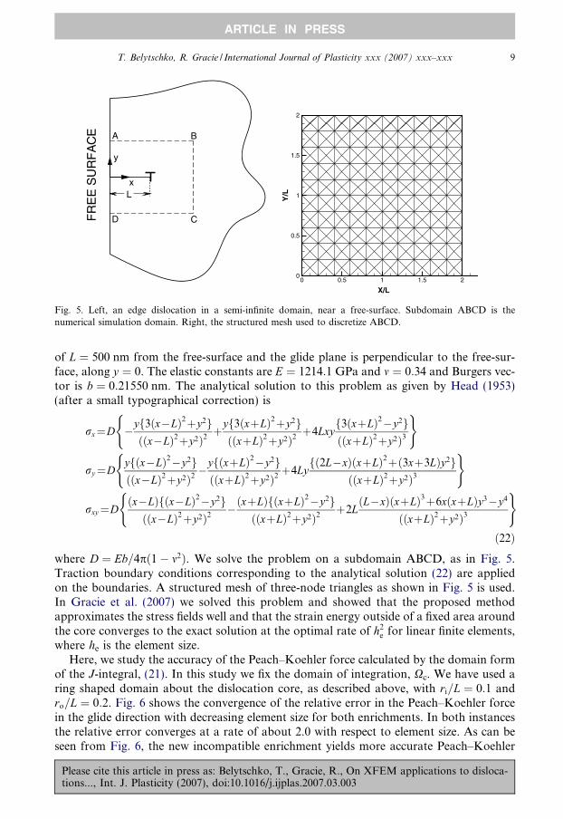
Fig. 5. Left, an edge dislocation in a semi-infinite domain, near a free-surface. Subdomain ABCD is thenumerical simulation domain. Right, the structured mesh used to discretize ABCD.
T. Belytschko, R. Gracie / International Journal of Plasticity xxx (2007) xxx–xxx 9
ARTICLE IN PRESS
of L ¼ 500 nm from the free-surface and the glide plane is perpendicular to the free-sur-face, along y ¼ 0. The elastic constants are E ¼ 1214:1 GPa and m ¼ 0:34 and Burgers vec-tor is b ¼ 0:21550 nm. The analytical solution to this problem as given by Head (1953)(after a small typographical correction) is
rx¼D �yf3ðx�LÞ2þy2gððx�LÞ2þy2Þ2
þyf3ðxþLÞ2þy2gððxþLÞ2þy2Þ2
þ4Lxyf3ðxþLÞ2�y2gððxþLÞ2þy2Þ3
( )
ry¼Dyfðx�LÞ2�y2gððx�LÞ2þy2Þ2
�yfðxþLÞ2�y2gððxþLÞ2þy2Þ2
þ4Lyfð2L�xÞðxþLÞ2þð3xþ3LÞy2g
ððxþLÞ2þy2Þ3
( )
rxy¼Dðx�LÞfðx�LÞ2�y2gððx�LÞ2þy2Þ2
�ðxþLÞfðxþLÞ2�y2gððxþLÞ2þy2Þ2
þ2LðL�xÞðxþLÞ3þ6xðxþLÞy3�y4
ððxþLÞ2þy2Þ3
( )ð22Þ
where D ¼ Eb=4pð1� m2Þ. We solve the problem on a subdomain ABCD, as in Fig. 5.Traction boundary conditions corresponding to the analytical solution (22) are appliedon the boundaries. A structured mesh of three-node triangles as shown in Fig. 5 is used.In Gracie et al. (2007) we solved this problem and showed that the proposed methodapproximates the stress fields well and that the strain energy outside of a fixed area aroundthe core converges to the exact solution at the optimal rate of h2
e for linear finite elements,where he is the element size.
Here, we study the accuracy of the Peach–Koehler force calculated by the domain formof the J-integral, (21). In this study we fix the domain of integration, Xc. We have used aring shaped domain about the dislocation core, as described above, with ri=L ¼ 0:1 andro=L ¼ 0:2. Fig. 6 shows the convergence of the relative error in the Peach–Koehler forcein the glide direction with decreasing element size for both enrichments. In both instancesthe relative error converges at a rate of about 2.0 with respect to element size. As can beseen from Fig. 6, the new incompatible enrichment yields more accurate Peach–Koehler
Please cite this article in press as: Belytschko, T., Gracie, R., On XFEM applications to disloca-tions..., Int. J. Plasticity (2007), doi:10.1016/j.ijplas.2007.03.003

101
102
10
10
10
100
dimensionless element size L/dx
rela
tive
erro
r of
the
glid
e fo
rce
Compatible
Incompatible
Fig. 6. Convergence of the Peach–Koehler force calculated using the domain form of the J-integral with meshrefinement for an edge dislocation near a free-surface.
10 T. Belytschko, R. Gracie / International Journal of Plasticity xxx (2007) xxx–xxx
ARTICLE IN PRESS
forces. However, the values of the Peach–Koehler force are generally comparable, exceptfor certain mesh sizes. Some of these differences are due to the change in accuracy thatdepends on the relative location of the core in the element. It should be noted that thedomain over which the J-integral was computed was larger than would be practical inDD. Such a large domain was used only so that coarse meshes could be included in theconvergence study.
We also considered domain integrals of different domain sizes, for a mesh with 60 ele-ments along each boundary, which gives an element size of he ¼ 1
30L. The Peach–Koehler
force scaled by L is dependent only on material properties, i.e. F PK � L ¼ b2l=ð4pðm� 1ÞÞ.For the material properties considered here F PK � L ’ 3:555.
For the incompatible enrichment the Peach–Koehler force and the relative error aregiven in Table 1 in terms of the integration domain size. The first and second rows of Table1 show that using very small ri gives very poor results. Comparison of the third to fifthrows shows that when ri is relatively small, increasing ri can improve the accuracy of
Table 1Peach–Koehler force by the domain form of the J-integral for various integration domains for a mesh of 60� 60elements; he � 1
31L is the element size
ri ro F PK � L Relative error in FPK
1he 3he �1.995 0.441.5he 3he �4.307 0.211.5he 6he �3.784 6.4 � 10�2
2he 6he �3.459 2.7 � 10�2
3he 6he �3.522 9.1 � 10�3
3he 10he �3.499 1.6 � 10�2
6he 10he �3.482 2.0 � 10�2
6he 12he �3.481 2.1 � 10�2
Please cite this article in press as: Belytschko, T., Gracie, R., On XFEM applications to disloca-tions..., Int. J. Plasticity (2007), doi:10.1016/j.ijplas.2007.03.003
T. Belytschko, R. Gracie / International Journal of Plasticity xxx (2007) xxx–xxx 11
ARTICLE IN PRESS
the J-integral. In both cases this is a reflection of the fact that the stress field at the core isless accurate than that away from the core. The last three rows show that for very largedomains, increasing ri decreases the accuracy slightly. Therefore, the inner radius of theintegration domain should be chosen sufficiently far from the core, but still in the vicinityof the core.
4.2. Dislocation near a bimaterial interface
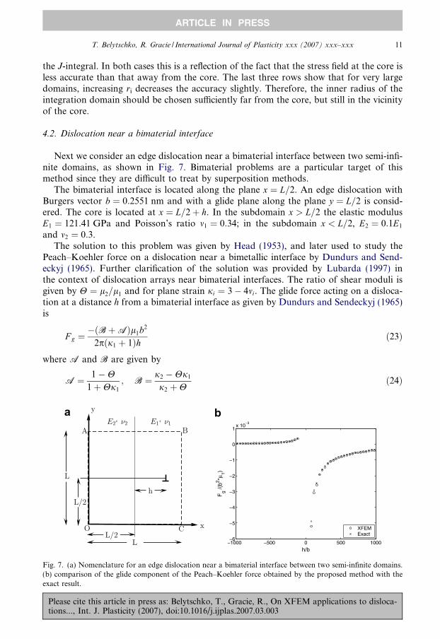
Next we consider an edge dislocation near a bimaterial interface between two semi-infi-nite domains, as shown in Fig. 7. Bimaterial problems are a particular target of thismethod since they are difficult to treat by superposition methods.
The bimaterial interface is located along the plane x ¼ L=2. An edge dislocation withBurgers vector b ¼ 0:2551 nm and with a glide plane along the plane y ¼ L=2 is consid-ered. The core is located at x ¼ L=2þ h. In the subdomain x > L=2 the elastic modulusE1 ¼ 121:41 GPa and Poisson’s ratio m1 ¼ 0:34; in the subdomain x < L=2, E2 ¼ 0:1E1
and m2 ¼ 0:3.The solution to this problem was given by Head (1953), and later used to study the
Peach–Koehler force on a dislocation near a bimetallic interface by Dundurs and Send-eckyj (1965). Further clarification of the solution was provided by Lubarda (1997) inthe context of dislocation arrays near bimaterial interfaces. The ratio of shear moduli isgiven by H ¼ l2=l1 and for plane strain ji ¼ 3� 4mi. The glide force acting on a disloca-tion at a distance h from a bimaterial interface as given by Dundurs and Sendeckyj (1965)is
F g ¼�ðBþAÞl1b2
2pðj1 þ 1Þh ð23Þ
where A and B are given by
A ¼ 1�H1þHj1
; B ¼ j2 �Hj1
j2 þHð24Þ
0 500 1000
0
1x 10
h/b
Fg /(
b2 *μ1)
XFEMExact
Fig. 7. (a) Nomenclature for an edge dislocation near a bimaterial interface between two semi-infinite domains.(b) comparison of the glide component of the Peach–Koehler force obtained by the proposed method with theexact result.
Please cite this article in press as: Belytschko, T., Gracie, R., On XFEM applications to disloca-tions..., Int. J. Plasticity (2007), doi:10.1016/j.ijplas.2007.03.003

12 T. Belytschko, R. Gracie / International Journal of Plasticity xxx (2007) xxx–xxx
ARTICLE IN PRESS
We consider a square L� L domain ABCD, L ¼ 1 lm, as shown in Fig. 7. Along the edgesof the domain, traction boundary conditions corresponding to the exact solution are ap-plied; the expressions for the stress fields are given in Lubarda (1997). We discretize thedomain with an unstructured mesh of 13,320 three-node triangular elements giving anaverage element edge length of about 15b.
In Fig. 7b, the glide component of the Peach–Koehler force obtained by the proposedmethod is compared to that from (23) for various distances, h, from the material interface.As can be seen, the glide force for the incompatible enrichment calculated with the domainform of the J-integral with ri ¼ 3he and ro ¼ 5he compares well with the exact result. Asthe dislocation approaches the interface, the accuracy decreases somewhat as a result ofinsufficient mesh resolution. When the number of elements separating the dislocation corefrom the interface was less than 5, we used ro ¼ h and ri ¼ h=2 for the domain integral,yielding less accurate results. Mesh refinement near the interface can be used to increasethe accuracy of the glide force calculation. Such refinement is easily accomplished sincethe element edges do not have to conform to the glide plane.
The convergence of the glide component of the Peach–Koehler force for both the com-patible and incompatible enrichments is shown in Fig. 8, for h=L ¼ 0:2. In this example,the incompatible enrichment is again more accurate than the compatible and regularizedenrichment for fine meshes. For both enrichments the relative error decreases non-mono-tonically with element size at a rate slightly greater than 1. The non-monotonic nature ofthe convergence curve is most likely a result of the fact that the size of the superimposedelement depends on not only the underlying mesh size but also the location of the dislo-cation core in the underlying element.
Contour plots of the shear stress, rxy, and for the normal stress, ryy, for the regularizedand compatible enrichment are shown in Figs. 9 and 10, respectively, with the correspond-ing contours for the exact solution for h=L ¼ 0:2. The stress contours show good agree-ment with the exact solution fields. We see that ryy is discontinuous across the material
100
101
102
10
10
100
dimensionless element size, h/dx
rela
tive
erro
r of
the
glid
e fo
rce
Compatible
Incompatible
Fig. 8. Convergence of the glide force on an edge dislocation near a bimaterial interface.
Please cite this article in press as: Belytschko, T., Gracie, R., On XFEM applications to disloca-tions..., Int. J. Plasticity (2007), doi:10.1016/j.ijplas.2007.03.003

X/h
Y/h
0 1 2 3 40
1
2
3
4
Sxy/mu1
0.00014E-05
-2E-05-8E-05-0.00014-0.0002-0.00026-0.00032-0.00038-0.00044-0.0005
X/h
Y/h
0 1 2 3 40
1
2
3
4
Sxy/mu1
0.00014E-05
-2E-05-8E-05-0.00014-0.0002-0.00026-0.00032-0.00038-0.00044-0.0005
Fig. 9. Comparison of the shear stress, rxy, contours from the proposed method (right) with those of the exactsolution (left) for an edge dislocation near a bimaterial interface.
T. Belytschko, R. Gracie / International Journal of Plasticity xxx (2007) xxx–xxx 13
ARTICLE IN PRESS
interface, but that rxy is continuous, as expected. Furthermore, mesh refinement near thedislocation core would improve the accuracy of the stresses in the vicinity of the core.
4.3. Slip-plane misorientation
We consider an edge dislocation in a square W � W , W ¼ 1 lm, bimaterial plate, asshown in Fig. 11; the body is supported only sufficiently to preclude rigid body motion,so the edges are otherwise free. The body is divided along the plane x ¼ W =2. In thedomain x > W =2 the elastic constants are E1 ¼ 121:41 GPa and m1 ¼ 0:34, while in thedomain x < W =2, E2 ¼ 0:1E1 and m2 ¼ 0:3. An edge dislocation is located in the domainx > W =2 at a distance of h from the point ðW =2;W =2Þ and oriented at an angle of h fromthe x-axis. The slip plane of the dislocation extends from the dislocation core to the pointðW =2;W =2Þ, where the glide plane crosses the material interface. Due to slip-plane misori-entation, the slip plane continues in the domain x < W =2 along the plane y ¼ W =2. Themagnitude of the Burgers vector, b ¼ 0:8551 nm, is assumed to be the same along boththe horizontal and inclined portions of the glide plane. Different Burger’s vector magni-tudes could have been adopted for each material.
This problem is solved using an unstructured mesh of 13,320 three node triangular ele-ments with an average element edge length of about 15b. For h=W ¼ 0:25 and h ¼ p=6 theshear stress contours are shown in Fig. 12. From these contours we can see that the pro-posed method predicts a residual dislocation at the material interface. The residual dislo-cation results from the incompatibility of the displacements where the slip plane intersectsthe material interface.
The glide and climb forces acting on an edge dislocation with h=W ¼ 0:1 for variousvalues of h between � p
6and p
6are shown in Fig. 13. The climb force is antisymmetric with
respect to h, while the glide force is symmetric, as expected. Because an unstructured meshwas used and because the method exhibits some mesh dependence, small perturbationsfrom perfect symmetry and antisymmetry are observed. The maximum glide force occurswhen h ¼ 0; however, glide forces of similar magnitude act to move the dislocationtowards the material interface when h ¼ � p
6.
Please cite this article in press as: Belytschko, T., Gracie, R., On XFEM applications to disloca-tions..., Int. J. Plasticity (2007), doi:10.1016/j.ijplas.2007.03.003

X/h
Y/h
0 1 2 3 40
1
2
3
4
Syy/mu1
0.00020.000160.000128E-054E-050
-4E-05-8E-05-0.00012-0.00016-0.0002
X/h
Y/h
0 1 2 3 40
1
2
3
4
Syy/mu1
0.00020.000160.000128E-054E-050
-4E-05-8E-05-0.00012-0.00016-0.0002
Fig. 10. Comparison of the y-direction stress, ryy, contours from the proposed method (right) with those of theexact solution (left) for an edge dislocation near a bimaterial interface.
Fig. 11. Edge dislocation in a simply supported bimaterial body with slip plane misorientation across the materialinterface. Dashed line represents the material interface; dotted line represents the slip plane.
14 T. Belytschko, R. Gracie / International Journal of Plasticity xxx (2007) xxx–xxx
ARTICLE IN PRESS
4.4. Finite body with multiple material interfaces
To illustrate the capability of the method to deal with more complicated geometries, weconsider a multimaterial body with four different materials and five material interfaces, asshown in Fig. 14. The domain dimensions are h� L where h ¼ 1000 nm ¼ 1169:5b andL ¼ 2h. The elastic properties in each section of the body are E1 ¼ 1000 GPa, m1 ¼ 0:34,E2 ¼ 0:1E1, m2 ¼ 0:30, E3 ¼ 2 � E1, m3 ¼ 0:2, and E4 ¼ 0:005E1, m14 ¼ 0:25. The bottomedge of the body is rigidly constrained while the top edge is prescribed a displacement cor-responding to 2% shear strain. Ten slip planes parallel to the x-axis are evenly distributedthroughout the system. Along each slip plane n dislocations are randomly distributed.Each dislocation is assumed to have the same Burgers vector b ¼ 0:8551 nm directed inthe x-direction. This problem would be challenging for superposition methods since the
Please cite this article in press as: Belytschko, T., Gracie, R., On XFEM applications to disloca-tions..., Int. J. Plasticity (2007), doi:10.1016/j.ijplas.2007.03.003

X/h
Y/h
0 1 2 3 40
1
2
3
4
Sxy/mu1
5E-054E-053E-052E-051E-050
-1E-05-2E-05-3E-05-4E-05-5E-05
X/h
Y/h
0 1 2 3 4
1
2
3
4
Sxx/mu1
5E-054E-053E-052E-051E-050
-1E-05-2E-05-3E-05-4E-05-5E-05
Fig. 12. Contours of: (a) the shear stress rxy and (b) the x-direction stress rxx for an edge dislocation in abimaterial plate with slip plane misorientation across the material interface. h is the distance of the core of thedislocation in the bulk from that at the material interface.
0 pi/12 pi/6
0
2
4
6x 10
Angle θ
For
ce [F
/(h2 μ 1)]
GlideClimb
Fig. 13. Glide and climb force acting on the edge dislocation from Fig. 11 for various values of h and h=W ¼ 0:1.
T. Belytschko, R. Gracie / International Journal of Plasticity xxx (2007) xxx–xxx 15
ARTICLE IN PRESS
body has several materials, finite dimensions, and the material interfaces are not parallel.The relative reduction in the force required to produce a 2% shear strain is shown inFig. 15. The required force decreases linearly with an increase in the number of disloca-tions because the number of slip planes containing dislocations was fixed. If the numberof these slip planes was varied, the required force would not decrease linearly with anincrease in the number of dislocations. A more realistic analysis of the above system wouldrequire a full DD simulation, likely in 3D. However, the potential of this method to solveproblems involving the interaction of dislocations with material interfaces has beendemonstrated.
Please cite this article in press as: Belytschko, T., Gracie, R., On XFEM applications to disloca-tions..., Int. J. Plasticity (2007), doi:10.1016/j.ijplas.2007.03.003

Fig. 14. Nomenclature for the problem of a body with multiple materials.
0 20 40 60 80 1000
0.2
0.4
0.6
0.8
Number of Dislocations
Rel
ativ
e R
educ
tion
in L
oad
Fig. 15. Percent reduction in applied force required to produce a 2% shear strain in the multimaterial problem.
16 T. Belytschko, R. Gracie / International Journal of Plasticity xxx (2007) xxx–xxx
ARTICLE IN PRESS
5. Conclusions
An extended finite element method (XFEM) for modelling dislocations in systems withmultiple arbitrary material interfaces was presented. The method uses a standard finite ele-ment method (FEM) to determine the total stress field subject to prescribed internal dis-continuities, i.e. the dislocation slip.
Since the method presented here uses a FEM to determine the total stress field, the meshmust be sufficiently refined to capture the high gradients of the stress field near the core. Somore resolution is needed than in the method of Van der Giessen and Needleman (1995)where only the image stress field is determined by the FEM. The method has two advan-tages over superposition and image field methods. (a) The method scales linearly with thenumber of dislocations for a given mesh since the Peach–Koehler force can be determinedfrom local quantities and its computational complexity does not depend on the number of
Please cite this article in press as: Belytschko, T., Gracie, R., On XFEM applications to disloca-tions..., Int. J. Plasticity (2007), doi:10.1016/j.ijplas.2007.03.003

T. Belytschko, R. Gracie / International Journal of Plasticity xxx (2007) xxx–xxx 17
ARTICLE IN PRESS
dislocations in the domain. (b) The method is applicable to problems of multiple arbitrarymaterial interfaces and is easily extended to anisotropic materials.
At this time it is not clear if the proposed method offers an advantage over superposi-tion based models for DD in a single isotropic material. However, the goal of the workhere is not to replace superposition models in their current applications, but to presenta method capable of treating new applications involving material interfaces, which are dif-ficult for existing methods.
We have examined the suitability and accuracy of contour integral methods to calculatethe Peach–Koehler force. We have shown that accuracies of about 98% can be obtainedeven with contours of moderate dimensions (between 3 and 5 times the element size inthe calculations reported). This would be disadvantageous for dislocation dynamics sim-ulations, since the dislocations are often in close proximity in such simulations. However,the contour integral method for the Peach–Koehler force can be advantageous since itrequires only local quantities and so does not directly depend on the number of disloca-tions in the domain.
Compatible and incompatible enrichments have been considered. The incompatibleenrichment yields more accurate results; however, the accuracy of the two enrichmentsis of the same order, which suggests that for the cases considered here the details of thecore representation do not significantly affect the results.
To demonstrate the accuracy and convergence of the method for problems with inter-faces, we have reported calculations for a single edge dislocation adjacent to an interfaceand for an edge dislocation interacting with a bimaterial interface. In both problems, com-parison to analytical results were made. For the discretizations considered, relative errorsof 2% were obtained for element sizes of 0:1–0:075 times the separation distance of the dis-location from the interface. The linear elements we have programmed so far have a limitedability to approximate the high strain gradients in the vicinity of the dislocation core. Theuse of higher-order elements is expected to greatly improve the accuracy of the method.
It is unclear at this time exactly what the niche for this method will be. None of theavailable methods have the versatility of the proposed method in terms of geometry, mate-rial properties and nonlinearities. The method requires more resolution than methodsbased on Green’s functions and image fields, but the required resolution is comparableto the Phase Field Method which has solved very large problems, see Wang et al.(2001). Furthermore, its compatibility with standard FEM software should proveattractive.
Acknowledgements
This work was supported by the Army Research Office under Grant W911NF-05-0049,the National Science Foundation under Grant CMS00304472 and the Natural Sciencesand Engineering Research Council of Canada under a graduate scholarship.
References
Amodeo, R.J., Ghoniem, N.M., 1990. Dislocation dynamics. I. A proposed methodology for deformation
micromechanics. Phys. Rev. B 41, 6958–6967.
Balint, D.S., Deshpande, V.S., Needleman, A., Van der Giessen, E., 2006. Size effects in uniaxial deformation of
single and polycrystals: a discrete dislocation plasticity analysis. Modell. Simulat. Mat. Sci. Eng. 14 (3), 409–
422.
Please cite this article in press as: Belytschko, T., Gracie, R., On XFEM applications to disloca-tions..., Int. J. Plasticity (2007), doi:10.1016/j.ijplas.2007.03.003

18 T. Belytschko, R. Gracie / International Journal of Plasticity xxx (2007) xxx–xxx
ARTICLE IN PRESS
Batra, R.C., 1987. The force on a lattice defect in an elastic body. J. Elasticity 17 (1), 3–8.
Belytschko, T., Black, T., 1999. Elastic crack growth in finite elements with minimal remeshing. Int. J. Num.
Meth. Eng. 45, 601–620.
Belytschko, T., Moes, N., Usui, S., Parimi, C., 2001. Arbitrary discontinuities in finite elements. Int. J. Num.
Meth. Eng. 50, 993–1013.
Canova, G., Brechet, Y., Kubin, L.P., DeVincre, B., Pontikis, V., Condat, M., 1993. 3d simulation of dislocation
motion on a lattice: application to the yield surface of single crystals. Solid State Phenom., 101–106.
Dundurs, J., Sendeckyj, G.P., 1965. Behavior of an edge dislocation near a bimetallic interface. J. Appl. Phys. 36
(10), 3353–3354.
Eshelby, J.D., 1951. The force on an elastic singularity. Philos. Trans. Roy. Soc. Lond. Ser. A, Math. Phys. Sci.
244 (877), 87–112.
Espinosa, H.D., Panico, M., Berbenni, S., Schwarz, K.W., 2006. Discrete dislocation dynamics simulations to
interpret plasticity size and surface effects in freestanding fcc thin films. Int. J. Plasticity 22 (11), 2091–2117.
Fivel, M.C., Gosling, T.J., Canova, G.R., 1996. Implementing image stresses in a 3d dislocation simulation.
Modell. Simulat. Mat. Sci. Eng. 4 (6), 581–596.
Ghoniem, N.M., Han, X., 2005. Dislocation motion in anisotropic multilayer materials. Philos. Mag. 85 (24),
2809–2830.
Ghoniem, N.M., Tong, S.-H., Sun, L.Z., 2000. Parametric dislocation dynamics: a thermodynamics-based
approach to investigations of mesoscopic plastic deformation. Phys. Rev. B 61 (2), 913–927.
Gracie, R., Ventura, G., Belytschko, T., 2007. A new fast method for dislocations based on interior
discontinuities. Int. J. Num. Meth. Eng. 69, 423–441.
Han, X., Ghoniem, N.M., 2005. Stress field and interaction forces of dislocations in anisotropic multilayer thin
films. Philos. Mag. 85 (11), 1205–1225.
Head, A.K., 1953. Edge dislocations in inhomogeneous media. Proc. Phys. Soc. Sec. B 66 (9), 793–801.
Lemarchand, C., Devincre, B., Kubin, L.P., 2001. Homogenization method for a discrete-continuum simulation
of dislocation dynamics. J. Mech. Phys. Solids 49 (9), 1969–1982.
Lubarda, V.A., 1997. Energy analysis of dislocation arrays near bimaterial interfaces. Int. J. Solids Struct. 34 (9),
1053–1073.
Moes, N., Dolbow, J., Belytschko, T., 1999. A finite element method for crack growth without remeshing. Int. J.
Num. Meth. Eng. 46, 131–150.
Moran, B., Shih, C.F., 1987. A general treatment of crack tip contour integrals. Int. J. Fract. 35 (4), 295–310.
Nabarro, F.R.N., 1947. Dislocations in a simple cubic lattice. Proc. Phys. Soc. 59 (2), 256–272.
Nicola, L., Van der Giessen, E., Needleman, A., 2005. Size effects in polycrystalline thin films analyzed by discrete
dislocation plasticity. Thin Solid Films 479 (1-2), 329–338.
Peach, M., Koehler, J.S., 1950. The forces exerted on dislocations and the stress fields produced by them. Phys.
Rev. 80 (3), 436–439.
Peierls, R., 1940. The size of a dislocation. Proc. Phys. Soc. 52 (1), 34–37.
Polonsky, I.A., Keer, L.M., 1996. Simulation of microscopic elastic–plastic contacts by using discrete
dislocations. Proc. Math. Phys. Eng. Sci. 452 (1953), 2173–2194.
Rice, J.R., 1968. A path independent integral and approximate analysis of strain concentration by notches and
cracks. J. Appl. Mech. 35 (2), 379–386.
Shehadeh, M.A., Zbib, H.M., de la Rubia, T.D., 2005. Multiscale dislocation dynamics simulations of shock
compression in copper single crystal. Int. J. Plasticity 21 (12), 2369–2390.
Van der Giessen, E., Needleman, A., 1995. Discrete dislocation plasticity: a simple planar model. Modell.
Simulat. Mat. Sci. Eng. 3, 689–735.
Ventura, G., Moran, B., Belytschko, T., 2005. Dislocations by partition of unity. Int. J. Numer. Meth. Eng. 62
(11), 1463–1487.
Volterra, V., 1907. Sur l’equilibre des corps elastiques multiplement connexes. Ann. Sci. ’Ecole Norm. Superieure
Ser. 3 (24), 401–517.
Wang, Y.U., Jin, Y.M., Cuitino, A.M., Khachaturyan, A.G., 2001. Nanoscale phase field microelasticity theory
of dislocations: model and 3D simulations. Acta Mater. 49 (10), 1847–1857.
Xiang, Y., Cheng, L.T., Srolovitz, D.J., Weinan, E., 2003. A level set method for dislocation dynamics. Acta
Mater. 51 (18), 5499–5518.
Zbib, H.M., Rhee, M., Hirth, J.P., 1998. On plastic deformation and the dynamics of 3d dislocations. Int. J.
Mech. Sci. 40, 113–127.
Please cite this article in press as: Belytschko, T., Gracie, R., On XFEM applications to disloca-tions..., Int. J. Plasticity (2007), doi:10.1016/j.ijplas.2007.03.003