On the use of WiMAX and Wi-Fi in a VANET to Provide in-Vehicle
84
On the use of WiMAX and Wi-Fi in a VANET to Provide in-Vehicle Connectivity and Media Distribution By Lerotholi Solomon Mojela Thesis presented in partial fulfilment of the requirements for the degree of Master of Science in Engineering at the Faculty of Engineering, Stellenbosch University Supervisor: Mr. Thinus Booysen Department of Electrical and Electronic Engineering December 2011
Transcript of On the use of WiMAX and Wi-Fi in a VANET to Provide in-Vehicle
On the use of WiMAX and Wi-Fi in a VANET toProvide in-Vehicle Connectivity and Media
Distribution
By
Lerotholi Solomon Mojela
Thesis presented in partial fulfilment of the requirements for the degree ofMaster of Science in Engineering
at the Faculty of Engineering, Stellenbosch University
Supervisor: Mr. Thinus BooysenDepartment of Electrical and Electronic Engineering
December 2011

i
Declaration
By submitting this thesis electronically, I declare that the entirety of the work contained therein is my own,
original work, that I am the sole author thereof (save to the extent explicitly otherwise stated), that reproduction
and publication thereof by Stellenbosch University will not infringe any third party rights and that I have not
previously in its entirety or in part submitted it for obtaining any qualification.
Date: December 2011
Copyright © 2011 University of Stellenbosch
All rights reserved
Stellenbosch University http://scholar.sun.ac.za
ii
Abstract
On the use of WiMAX and Wi-Fi in a VANET to Provide in-
vehicle Connectivity and Media Distribution
L.S. Mojela
Department of Electrical and Electronic Engineering
Stellenbosch University
Private Bag X1, 7602 Matieland, South Africa
Thesis: M.Sc.Eng (Electronic)
December 2011
The recent emergence of ubiquitous wireless connectivity and the increasing
computational capacity of modern vehicles have triggered immense interest in the
possibilities of vehicular connectivity. A plethora of potential applications for vehicular
networks have been proposed in the areas of safety, traffic infrastructure management,
information, and entertainment. The broad range of applications requires creative utilisation
of the available wireless medium, using a combination of existing and novel wireless
technologies. In this research the evaluation of one such configuration is performed.
Dedicated short range communication for safety applications is assumed, and the use of Wi-
Fi and WiMAX for non-safety applications is evaluated. Little is known about the media
streaming performance of these wireless technologies in realistic vehicular ad-hoc network
(VANET) scenarios. Due to the extreme mobility and unpredictable environmental aspects in
a real road environment, an empirical evaluation is performed and presented. Evaluation of a
multi-vehicle to infrastructure (V2V2I) VANET, using Wi-Fi for the vehicle-to-vehicle
communication and WiMAX for the vehicle to infrastructure (V2I) communication is
experimented. It is observed that Wi-Fi is unaffected by the vehicle speed; whenever nodes
are within communication range, data gets transferred normally. A detailed characterisation
of the network architecture is presented and the results show that a multitude of applications
can be supported with this proposed network architecture.
Stellenbosch University http://scholar.sun.ac.za

iii
Samevatting
Die Gebruik van WiMAX en Wi-Fi vir Netwerkkommunikasie
en Mediaverspreiding in 'n VANET
L.S. Mojela
Departement van Elektriese en Elektroniese Ingenieurswese
Stellenbosch Universiteit
Privaatsak X1, 7602 Matieland, Suid Afrika
Tesis: M.Sc.Ing (Electronies)
Desember 2011
Die toenemende beskikbaarheid en digtheid van koordlose netwerke en die verhoogde
verwerkingsvermoëns van moderne voertuie het die afgelope paar jaar aansienlike
belangstelling gewek in die moontlikhede wat voertuig-kommunikasie bied. ʼn Magdom
moontlike toepassings is voorgestel in ʼn wye verskeidenheid van velde insluitende veiligheid,
verkeersinfrastruktuur, informasie en vermaak. Hierdie voorstelle vereis die kreatiewe
benutting van die beskikbare en nuwe koordlose tegnologieë. Hierdie tesis evalueer een
voorbeeld van so ‘n opstelling. ʼn Toegewyde kortafstand kommunikasie modus vir
veiligheidstoepassings word aangeneem, terwyl Wi-Fi en WiMAX vir ander toepassings
evalueer word. Daar is min navorsing oor die kapasiteit en seinsterkte van hierdie beskikbare
netwerke onder realistiese voertuig netwerk (VANET) scenario‘s. Weens die hoë mobiliteit
van voertuie en ook die onvoorspelbaarheid van hierdie omgewing word ʼn empiriese
evaluasie beskou as die mees gepaste metode. Die navorsing ondersoek ʼn multi-voertuig-tot-
infrastruktuur-netwerk wat Wi-Fi gebruik vir voertuig-tot-voertuig (V2V) kommunikasie en
WiMAX vir voertuig-tot-infrastruktuur (V2I) kommunikasie. Die navorsing bevind dat Wi-Fi
nie beïnvloed word deur die spoed van die voertuig nie: wanneer die nodes binne die bereik is
van die netwerk word data normaal oorgedra. ‗n Gedetailleerde karakterisering van dié
netwerk word gedoen en die resultate dui aan dat ‗n groot hoeveelheid toepassings
ondersteun kan word deur dié opstelling.
Stellenbosch University http://scholar.sun.ac.za
iv
Acknowledgements
I would like to pass my sincere regards to the following:
My supervisor Mr. Thinus Booysen for guidance and support throughout the
research,
My colleagues in the research group for their contribution and discussions,
MIH for the financial support,
My family for their unending support
Stellenbosch University http://scholar.sun.ac.za

v
Dedications
To my family who have urged, encouraged and supported me to continue with my
studies.
Stellenbosch University http://scholar.sun.ac.za

vi
Table of Contents Declaration .................................................................................................................................. i
Abstract ...................................................................................................................................... ii
Samevatting.............................................................................................................................. iii
Acknowledgements ................................................................................................................... iv
Dedications ................................................................................................................................ v
List of Figures ........................................................................................................................ viii
List of Tables ............................................................................................................................ ix
List of Abbreviations ................................................................................................................. x
Chapter 1 Introduction .......................................................................................................... 1
1.1 Background to Study............................................................................................ 1
1.2 Problem Specification .......................................................................................... 6
1.3 Results Overview ................................................................................................. 7
1.4 Thesis Outline ...................................................................................................... 8
Chapter 2 Literature Survey ................................................................................................. 9
2.1 VANETs Characteristics and Challenges ............................................................ 9
2.2 VANETs Communication Architectures ........................................................... 12
2.3 Routing and Data Dissemination in VANETs ................................................... 14
2.4 VANETs Applications and Classification ......................................................... 17
2.5 Wireless Access Methods in VANETs/Access Technologies ........................... 18
2.5.1 Short/Medium Range Wireless Technologies ............................................ 19
2.5.2 Wide/Long Range wireless technologies ................................................... 28
2.6 Approaches in Literature Survey ....................................................................... 33
Chapter 3 Experimental Setup ............................................................................................ 37
3.1 Used Equipment and Configuration ................................................................... 39
3.1.1 Wi-Fi Configuration ................................................................................... 41
3.1.2 WiMAX Configuration............................................................................... 42
Stellenbosch University http://scholar.sun.ac.za
vii
3.1.3 Network Monitoring Tools ......................................................................... 43
3.2 Experimental Approach ..................................................................................... 44
3.2.1 Wi-Fi Only Tests (V2R and V2V) ............................................................. 44
3.2.2 WiMAX Only Tests (V2I) .......................................................................... 45
3.2.3 Wi-Fi and WiMAX (V2V2I) ...................................................................... 45
3.2.4 Live Audio and Video Streaming ............................................................... 46
Chapter 4 Results and Discussion ...................................................................................... 47
4.1 Vehicle to Roadside (Wi-Fi - IEEE802.11g) ..................................................... 47
4.2 Vehicle to Vehicle communication (Wi-Fi - IEEE802.11n) ............................. 50
4.2.1 Vehicles following each other .................................................................... 50
4.2.2 Vehicles moving in opposite directions ...................................................... 51
4.3 Vehicle to Infrastructure communication (WiMAX - IEEE802.16d-2004) ...... 52
4.3.1 Vehicle on LOS route ................................................................................. 53
4.3.2 Vehicle on NLOS route .............................................................................. 53
4.4 Vehicle to Vehicle to Infrastructure communication (Wi-Fi - IEEE802.11n and
WiMAX -IEEE802.16d) ...................................................................................................... 54
4.4.1 Vehicles following each other .................................................................... 54
4.4.2 Vehicles moving in opposite directions ...................................................... 56
4.5 Result Summary ................................................................................................. 57
4.6 Applicability of Presented Results ..................................................................... 59
Chapter 5 Conclusion ......................................................................................................... 61
Chapter 6 Future Work ....................................................................................................... 62
List of References .................................................................................................................... 63
Stellenbosch University http://scholar.sun.ac.za

viii
List of Figures
Figure 1.1. Illustration of a vehicular network ................................................................... 2
Figure 1.2. V2V2I system components and functionality .................................................. 5
Figure 1.3. V2V2I architecture using Wi-Fi and WiMAX ................................................ 7
Figure 2.1. Hidden node problem: node A hidden from node C and vice versa ................ 9
Figure 2.2. Exposed node problem: node A exposed to node C and vice versa .............. 10
Figure 2.3. IEEE 802.11 MAC Layer .............................................................................. 20
Figure 2.4. IEEE 802.11 PHY Layer................................................................................ 21
Figure 2.5. DSRC spectrum allocation and channels in the U.S. ..................................... 25
Figure 3.1. Open space for V2R experiments using Wi-Fi (802.11g) ............................. 38
Figure 3.2. Area where V2V2I experiments were conducted in Stellenbosch Campus .. 39
Figure 3.3. Initial V2V performance tests using Wi-Fi .................................................... 45
Figure 3.4. V2I performance tests using WiMAX ........................................................... 45
Figure 3.5. V2V2I tests using combination of Wi-Fi and WiMAX ................................. 46
Figure 4.1. Average throughput as the car travels at 60km/h........................................... 48
Figure 4.2. Average signal strength as the car travels at 60km/h ..................................... 48
Figure 4.3. Overall performance of IEEE 802.11g in V2R at vehicular speeds .............. 49
Figure 4.4. Signal strength received for different vehicular speeds ................................. 50
Figure 4.5. Throughput measured for different vehicular speeds .................................... 50
Figure 4.6. V2V communication for vehicles following.................................................. 51
Figure 4.7. V2V communication for vehicles crossing .................................................... 52
Figure 4.8. V2I communication in LOS condition ........................................................... 53
Figure 4.9. V2I communication in NLOS condition ........................................................ 53
Figure 4.10. V2V2I following under LOS condition ....................................................... 55
Figure 4.11. V2V2I following under NLOS condition .................................................... 55
Figure 4.12. V2V2I moving in opposite direction LOS ................................................... 56
Figure 4.13. V2V2I moving in opposite direction in NLOS ............................................ 57
Stellenbosch University http://scholar.sun.ac.za

ix
List of Tables
Table 1. DSRC Regional Standards ................................................................................. 26
Table 2. Comparison of physical layer implementations in IEEE 802.11a and IEEE
802.11p..................................................................................................................................... 28
Table 3. IEEE 802.16 Standards comparison ................................................................... 29
Table 4. Results logged and calculated for each communication architecture ................ 40
Table 5. Wi-Fi configurations .......................................................................................... 42
Table 6. IEEE 802.16-2004 (Fixed WiMAX) configurations .......................................... 43
Table 7. Wi-Fi and WiMAX performance in different VANET architectures ............... 59
Table 8. VANET applications with data rate requirement ............................................... 60
Table 9. Applications as per communication architecture ............................................... 60
Stellenbosch University http://scholar.sun.ac.za

x
List of Abbreviations
AODV Ad hoc On-demand Distance Vector
AU Application Unit
BMMM Batch Mode Multicast MAC
BMW Broadcast Medium Window
BPSK Binary Phase Shift Keying
C2C CC Car-to-Car Communication Consortium
CAR Connectivity Aware Routing
CCK Complementary-Code Keying
COIN Clustering for Open IVC Network
CSMA/CA Carrier Sense Multiple Access with Collision Avoidance
DCF Distributed Coordination Function
DREAM Distance Routing Effect Algorithm for Mobility
DSDV Destination-Sequenced Distance-Vector
DSR Dynamic Source Routing
DSRC Dedicated Short-Range Communication
DSSS Direct Sequence Spread Spectrum
EDGE Enhanced Data rates for Global Evolution
ETSI European Telecommunications Standards Institute
FHSS Frequency Hopping Spread Spectrum
GPRS General Packet Radio Service
GPSR Greedy Perimeter Stateless Routing
GSM Global System for Mobile communications
HIPERLAN High Performance Radio LAN
HSPA High Speed Packet Access
HWN Heterogeneous Wireless Network
IEEE Institute of Electrical and Electronics Engineers
ITS Intelligent Transportation Systems
LAN Local Area Networks
LLC Logical Link Control layer
LTE Long Term Evolution
MAC Media Access Control
Stellenbosch University http://scholar.sun.ac.za

xi
MAN Metropolitan Area Network
MANET Mobile Ad hoc Network
MIMO Multiple-Input Multiple-Output
MLME MAC Layer Management Entity
NAV Network Allocation Vector
OBU On Board Unit
OFDM Orthogonal Frequency Division Multiplexing
PCF Point Coordination Function
PDA Personal Digital Assistant
PHY PHYsical Layer
PLCP Physical Layer Convergence Protocol
PMD Physical Medium Dependent
QAM Quadrature Amplitude Modulation
QoS Quality of Service
QPSK Quadrature Phase Shift Keying
RSU Road-Side Unit
RTS/CTS Request-To-Send/Clear-To-Send
SME Station Management Entity
SPAWN Swarming Protocol for vehicular Ad-hoc Wireless Network
TCP Transport Control Protocol
UDP User Datagram Protocol
UMB Urban Multi-hop Broadcast
UMTS Universal Mobile Telecommunications System
V2I Vehicle-to-Infrastructure
V2R Vehicle-to-Roadside
V2V Vehicle-to-Vehicle
V2V2I Vehicle-to-Vehicle-to-Infrastructure
VANET Vehicular Ad hoc Network
WAVE Wireless Access in the Vehicular Environment
Wi-Fi Wireless Fidelity
WiMAX Worldwide Interoperability for Microwave Access
WLAN Wireless Local Area Networks
ZOR Zone of Relevance
Stellenbosch University http://scholar.sun.ac.za

1
Chapter 1 Introduction
1.1 Background to Study
Given the fact that today vehicles play an important role in peoples‘ lives, embedding
software-based intelligence into cars has the potential to intensely improve the passengers‘
quality of life. Vehicular networks provide a promising platform for a much broader range of
large scale, highly mobile applications. This, along with the high market demand for more
reliability, safety and entertainment in automobiles, has resulted in massive development and
support of vehicular networks and its applications [1]. Some of these applications are
conventional mobile internet access applications, like downloading files, reading e-mail while
on the move, etc. Others involve the discovery of local services in the neighbourhood by
using the vehicle grid as an ad-hoc network, e.g., restaurants, movie theatres, etc. Others
demand close interaction among vehicles such as interactive vehicle-based games. The
demands of these applications give the list of requirements and challenges for vehicular
applications.
Car manufacturers together with national government agencies have joined forces to
come up with ideas and technologies that could assist drivers and commuters on the roads.
This involves supplying of safety and comfort information. At the same time, universities and
research organisations are working on adapting existing technologies and developing new
ones for the vehicular networking environment. One such effort is the development and
deployment of Intelligent Transportation Systems (ITS) which is the primary driver for the
research on inter-vehicular communications [2]. ITS aims to minimize accidents and improve
traffic conditions by introducing information exchange between vehicles, drivers and
passengers through the use of wireless communication. The deployment of such information
exchange mechanism is achieved by the implementation of wireless vehicular networking
also known as Vehicular Ad hoc Network (VANET), Figure 1.1. As shown in the figure,
interaction between two vehicles is enabled by the use of short range wireless technologies,
Wi-Fi and or WAVE, depending on the interaction type. Furthermore, vehicles can connect to
other infrastructure networks and the Internet through Wi-Fi hotspots or long/wide range
wireless technologies, WiMAX and or cellular. Additionally vehicles can interact with the
traffic operators and other concerned agencies through roadside units. Roadway information
Stellenbosch University http://scholar.sun.ac.za

CHAPTER 1. INTRODUCTION 2
and route planning is often available from positioning systems and map-based technologies
such as GPS.
Vehicular networking is an emerging technology that will enable vehicles to
communicate with each other, vehicle-to-vehicle (V2V) communication, and with fixed
roadside units or the Internet cloud, vehicle-to-infrastructure (V2I) communication, or a
hybrid of the two, called vehicle-to-vehicle-to-infrastructure (V2V2I) communication[1,3,4].
VANETs are a special case of Mobile Ad hoc Networks (MANETs) where the nodes
(vehicles) are characterised by high mobility on predictable paths or directions due to
roadways, but unlike MANETs, they are not constrained in terms of energy and storage. The
sudden speed and direction changes which cause rapid network topology changes impose a
number of challenges [1, 5], for example, message routing due to short lived communication
links, signal degradation due to Doppler effects and multipath fading, and medium access
control of the shared wireless medium [6].
Figure 1.1. Illustration of a vehicular network
GPS
Navigation
RSU
WAVE
Wi-Fi (hotspots)
WiMAX/Cellular
Internet
Operator/End user
WAVE/Wi-Fi
Petrol station
Stellenbosch University http://scholar.sun.ac.za

CHAPTER 1. INTRODUCTION 3
The ability to equip vehicles with sensing and control devices makes vehicles an ideal
platform for mobile data gathering especially in the context of monitoring surrounding
environments (i.e., vehicular sensor networks) [7, 8, 9, 10, 11]. Awareness of the immediate
surroundings on the current location and interworking amongst vehicles can guarantee safe
and efficient travelling. Compared to the traditional sensor networks, vehicular sensors have
fewer constraints on processing power and storage capabilities, and they can generate and
handle data at a higher rate. Therefore, each vehicle can then sense events, process sensed
data and route the data to other vehicles. Moreover, the sensing coupled with the in-car
navigation systems, high bandwidth wireless communications and protocols for mobile ad
hoc networks can lead to a number of vehicular networking applications [12]. These
applications could be then used to supply vehicles with traffic information that could make
drivers aware of their surrounding environment, which in turn will assist them in making
informed decisions and reacting timeously. In addition, the in advance warnings can prepare
a vehicle's safety systems, such as anti-brake lock systems, air bags and pre-tension safety
belts, in the event of an impending collision.
The applications proposed for VANETs can broadly be classified into safety and non-
safety applications [13, 14]. Safety applications convey safety critical information based on
sensor data from other cars or roadside units to report and avoid crashes and emergencies [1,
13]. Examples include a sudden brake warning sent from a remote preceding car, information
about road conditions and maintenance, and accident annunciations. Non-safety applications,
which have received less attention in the literature, include entertainment and information on
general traffic management [1, 15, 16]. The non-safety applications (except some traffic
management applications) typically obtain data on-demand such that a node requests
information of interest [1, 14]. Examples of this are electronic payments, file sharing and
audio video streaming. A key aspect of these commercial applications is the availability of
high data rates and stable Internet connectivity.
VANET applications, which include safety messaging, traffic management and Internet
access, have different requirements of data rates, latency and infrastructure [17, 18]. Traffic
applications have relatively relaxed latency constraints and involve collecting information
from several sources (vehicles, road based sensors, highway cameras). Such applications can
be instantiated without infrastructure support, enabled by multi-hop communication and
networking. Safety communications, however, is concerned with exchanging state with
Stellenbosch University http://scholar.sun.ac.za

CHAPTER 1. INTRODUCTION 4
nearest neighbours to maintain safety in the system. As a result, the profile for data exchange
is expected to be of high frequency of updates with a small payload. A strict requirement is
high reliability of messages delivered, that is, the packet delivery ratio (PDR) and the average
delay of messages delivered.
When sharing a single communication medium, an important factor is the prioritization
of messages; safety applications should have higher priority. But sometimes non-safety
applications could already have flooded the network causing delay of critical messages. As
mentioned in [22], for VANETs to support different safety and non-safety applications with
different quality of service (QoS), nodes need to follow protocols that will enable them to
cooperate with each other. Thus a quality level of minimum latency and maximum reliability
cannot be achieved if existing radio bands are used and/or safety and non-safety
communications share the same frequency and bandwidth [35]. This necessitates the need for
a multi-channel radio system, having separate channels for both safety and non-safety
applications.
The Wireless Access in the Vehicular Environment (WAVE) specifications employs the
multi-channel technique by leveraging on the channel switching scheme. This recently
introduced standard, WAVE, (IEEE 802.11p) [21] is an enhancement of IEEE 802.11 to
support ITS applications, operating on the licensed spectrum from 5.85 to 5.925GHz,
occupying 75MHz. Alternatively, a realisation of WAVE could be used for safety
applications while the existing standards, like IEEE 802.11 (Wi-Fi) and IEEE 802.16 (Mobile
WiMAX), could be used for non-safety applications. Thus, employ the context of the
coexistence of different communication technologies for serving connectivity requirements in
the vehicular environments. Separating the applications by applying cross layer architecture,
as shown in Figure 1.2 below [22] can also improve overall system performance and
efficiently utilize resources.
Stellenbosch University http://scholar.sun.ac.za

CHAPTER 1. INTRODUCTION 5
Figure 1.2. V2V2I system components and functionality
Wi-Fi is a short range (+/-200 m) wireless local area network (WLAN) technology
protocol based on the IEEE 802.11 network standard [23] operating on an unlicensed radio
frequency of 2.4 GHz offering high data rates of up to 150 Mbps (IEEE 802.11n [24]). In this
investigation, IEEE 802.11n was used because it builds on previous 802.11 standards by
using only orthogonal frequency division multiplexing (OFDM), adding multiple-input
multiple-output (MIMO) and doubling of channel width 40 MHz channels to the PHY
(physical layer). WiMAX is a long range wireless metropolitan area network (WMAN)
technology providing up to 30 miles (50 km) for fixed stations, and 3 - 10 miles (5 - 15 km)
for mobile stations. It is based on the IEEE 802.16 standard [25] currently covering spectrum
ranges from 2 GHz range through 66 GHz range, with non-line-of-sight offered on lower
frequencies, 2 – 11 GHz, and line-of-sight offered on frequencies up to 66GHz. WiMAX is
further categorised in fixed WiMAX (IEEE 802.16d-2004) and mobile WiMAX (IEEE
802.16e-2005). We chose WiMAX because it is one of the next generation technologies
V2
V C
ross
-Lay
er I
nfo
rmat
ion
Co
ntr
oll
er
V2V2I Communication System
V2R/V2V Transport TCP/UDP
IP V2R/V2V Network
MAC & PHY
(WAVE/DSRC)
MAC & PHY
(Wi-Fi and WiMAX)
V2V2I Applications
Safety Applications Non-Safety
Applications
Stellenbosch University http://scholar.sun.ac.za

CHAPTER 1. INTRODUCTION 6
(NGN) currently available, but due to the limitation of equipment IEEE 802.16d-2004 was
used instead of a more suitable IEEE 802.16e.
1.2 Problem Specification
Vehicular networks have no fixed infrastructure and instead rely on the vehicles themselves
to provide network functionality. However, due to mobility constraints, driver behaviour and
high speeds, connectivity in VANETs is not always guaranteed. Like in other networks,
VANET applications have different requirements in terms of QoS i.e. latency/delay, data
rates, size of content to be distributed, distribution area, and push/pull based, number of
recipients (unicast/multicast/broadcast) and some are even interactive applications.
The lack of connectivity in vehicular networks can be an advantage for safety applications
since when the network is not connected (meaning vehicles are far apart) there is basically
low risk in terms of safety. On the other hand, commercial applications require constant
connectivity among vehicles to enable content and data sharing; hence the focus in this
research. In networking terms, data delivery is enabled by protocols; in particular for
VANETs, the protocols can be categorised as Geographical routing, Trajectory based routing,
and Opportunistic routing. But because communication links are usually short lived in
VANETs, content downloading and or uploading can only be done in blocks. Thus, when
designing these protocols, content data retrieval and indexing needs a special attention.
This research aims to give a thorough understanding of how vehicular networks will perform
under realistic vehicular environments which will in turn help in the development of VANET
applications and protocols. Because the focus is on commercial applications, quantitative
aspects of connection performance under various motional and environmental conditions
include:
- Contact time (duration) of a typical communication link; some applications
require long lived connections while others can survive on short lived
connections. Therefore this aspect will help to choose which link a node can
use to communicate on, for a particular application.
- Amount of data that can be transferred during a contact period; this is tested
on different behaviours in vehicular environment, from vehicles travelling in
opposite directions to vehicles following each other. Knowing the amount of
Stellenbosch University http://scholar.sun.ac.za

CHAPTER 1. INTRODUCTION 7
data that can be uploaded/downloaded for particular link duration will help in
creating data blocks and indexing.
- Instantaneous throughput while the link is active; some applications require
high throughput (e.g. voice/video) hence a decision to start an application can
be based on this aspect.
- Amount of jitter evident on the link; commercial applications are not strict in
terms of delay but others are sensitive to jitter.
Due to short lived contact periods between vehicles, high data rate technologies prove to
be more preferred in this type of networks. But because currently the long range wireless
technologies support lower data rates compared to short range wireless technologies; both are
used to provide higher data rates and wider coverage. This research therefore empirically
examines the performance of a simple VANET that uses Wi-Fi and WiMAX to realise
V2V2I network architecture as indicated in Figure 1.3. For the experiment Wi-Fi is used for
V2V communication and WiMAX for V2I communication. With the focus on non-safety
applications including Internet connectivity and media streaming, the network performance is
evaluated in built and unpopulated urban environment. Wi-Fi performance for V2V
communication is also investigated in a highway environment. The results show that the
network architecture employed provides a robust and functional channel for V2V, V2I and
V2V2I data delivery under specific scenarios.
Figure 1.3. V2V2I architecture using Wi-Fi and WiMAX
1.3 Results Overview
The results have been logged and analysed, and they are encouraging as far as mobility
and environmental conditions are concerned. The fixed experimental variables, nodes‘ speed
WiMAX
Wi-Fi
Wi-Fi
Stellenbosch University http://scholar.sun.ac.za

CHAPTER 1. INTRODUCTION 8
and environment (LOS/NLOS), affect the network quantitative aspects differently. As
expected, the contact time depends on communication range, node‘s direction and speed. On
the other hand communication range is affected by the environment; the obstacles limit the
maximum range that can be reached. The separation between the communicating nodes
affects the signal strength which in turn affects throughput (thus data transferable) and jitter.
Moreover, total data transferable as per connection depends on the contact period and
throughput. The implementation of video and voice also added a value on the results as they
showed the capability of an implemented network in terms of data handling.
These analytical results can help in development of routing protocols to predetermine the
duration/lifetime of a particular found path. With this information, a link can either be used or
dropped depending on an application of interest. Additionally, such a capability can lead to
better implementation and classification of applications.
1.4 Thesis Outline
The remainder of this paper is organised as follows:
Chapter 2 gives the literature review and overview of related work. The unique challenges
and characteristics of VANETs are discussed followed by presentation of communication
architectures currently available in VANETs and a brief analysis of routing protocols that
support vehicle-based applications is given, and finally an overview of available wireless
technologies in relation to vehicular networks.
Chapter 3 describes the experimental setup and equipment used to conduct this research. This
section presents factors and quantitative aspects that were taken into account when
conducting the research. It further gives the technologies used and their configuration.
Chapter 4 presents the results and their analysis with respect to the conditions described in
the previous section. The results are also compared to the findings in the literature.
Chapter 5 concludes the paper and gives the findings of the research.
Chapter 6 explores the envisioned future work to incorporate the findings of this research.
Stellenbosch University http://scholar.sun.ac.za

9
Chapter 2 Literature Survey
2.1 VANETs Characteristics and Challenges
VANETs have characteristics of topology and mobility similar to, yet distinct from
traditional mobile ad hoc networks (MANETs). However, due to mobility constraints,
drivers‘ behaviour, and high speeds, VANETs show characteristics that are completely
different from conventional MANETs. In VANETs the nodes (vehicles) travel at high speeds
mostly on predictable paths due to roadway topology: furthermore, they are less restricted in
terms of available energy, computation and storage [26]. The VANET nodes have much
higher power reserves than typical MANET nodes as they get their energy or power from
batteries that are constantly being charged as needed from the engine. The VANET nodes
have less size constraints than traditional MANET nodes, and therefore can support larger
computing and sensing devices. Moreover, many of the sensing devices are needed for
normal vehicle operation and already part of the vehicle. The abundant power source and
larger size allows VANET nodes to be equipped with larger powerful computers and data
storage as well as wireless devices with powerful transceivers supporting high data rates.
The use of wireless communication in VANETs presents specific challenges: As shown
in [27], there are two issues at the link layer that affect the throughput, the problems of
hidden nodes and exposed nodes. The hidden node problem occurs when two nodes outside
the interference range of one another have one or more nodes that are within the transmission
range of both. If they both try to transmit data at the same time, they cause a collision at one
of the nodes they share. As shown in Figure 2.1, nodes A and C are outside the transmission
range of each other but if they transmit to node B at the same time, a collision occurs.
Figure 2.1. Hidden node problem: node A hidden from node C and vice versa
Stellenbosch University http://scholar.sun.ac.za
CHAPTER 2. LITERATURE SURVEY 10
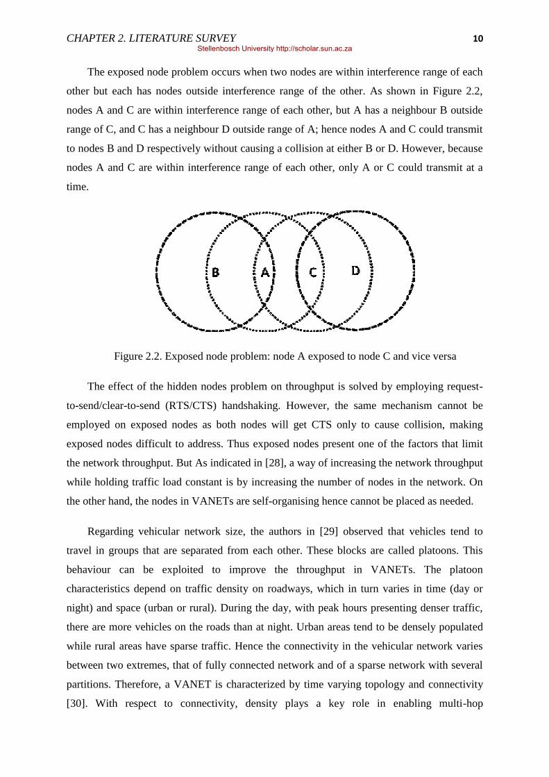
The exposed node problem occurs when two nodes are within interference range of each
other but each has nodes outside interference range of the other. As shown in Figure 2.2,
nodes A and C are within interference range of each other, but A has a neighbour B outside
range of C, and C has a neighbour D outside range of A; hence nodes A and C could transmit
to nodes B and D respectively without causing a collision at either B or D. However, because
nodes A and C are within interference range of each other, only A or C could transmit at a
time.
Figure 2.2. Exposed node problem: node A exposed to node C and vice versa
The effect of the hidden nodes problem on throughput is solved by employing request-
to-send/clear-to-send (RTS/CTS) handshaking. However, the same mechanism cannot be
employed on exposed nodes as both nodes will get CTS only to cause collision, making
exposed nodes difficult to address. Thus exposed nodes present one of the factors that limit
the network throughput. But As indicated in [28], a way of increasing the network throughput
while holding traffic load constant is by increasing the number of nodes in the network. On
the other hand, the nodes in VANETs are self-organising hence cannot be placed as needed.
Regarding vehicular network size, the authors in [29] observed that vehicles tend to
travel in groups that are separated from each other. These blocks are called platoons. This
behaviour can be exploited to improve the throughput in VANETs. The platoon
characteristics depend on traffic density on roadways, which in turn varies in time (day or
night) and space (urban or rural). During the day, with peak hours presenting denser traffic,
there are more vehicles on the roads than at night. Urban areas tend to be densely populated
while rural areas have sparse traffic. Hence the connectivity in the vehicular network varies
between two extremes, that of fully connected network and of a sparse network with several
partitions. Therefore, a VANET is characterized by time varying topology and connectivity
[30]. With respect to connectivity, density plays a key role in enabling multi-hop
Stellenbosch University http://scholar.sun.ac.za

CHAPTER 2. LITERATURE SURVEY 11
communication: different vehicle densities cause disconnections where vehicles are not able
to communicate. Thus, in networking terms, the nodes are partitioned from each other. As a
result, message propagation in the network is constrained by the occurrence of partitions
between nodes.
Network partitions and short lived paths between nodes caused by mobility present a
challenge in the routing layer. This necessitates implementation of routing techniques that
can efficiently handle fragmented networks and rapid topology changes. The currently
available routing techniques, proactive and reactive, used in traditional MANETs fail to
successfully handle these requirements for VANETs. Reactive protocols set up routes when a
node tries to transmit data, but the VANET links are short-lived hence could disappear as
soon as they are discovered. Proactive protocols on the other hand seeks to maintain routes to
every node, but with rapid topology changes in VANETs will result in overhead of routing
traffic as new routes will need to be discovered constantly. To overcome this challenge, the
authors in [31] argue that location-based routing is more appropriate as messages are
delivered to the nodes in the zone of relevance based on location stamp in the message.
Routing in VANETs is discussed in more detail in Section 2.3.
The issues of security and privacy also need to be addressed in vehicular networks. Like
in MANETs, because of lack of fixed infrastructure, nodes in VANETs rely on other nodes
which are unreliable to propagate data. Fake messaging should be detected and enforcement
of anonymity preservation for undependable parties to prevent vehicle tracking and
identification. In MANETs, secure routing techniques have included cryptography, including
hash chains and digital signatures, and the distribution of public key certificates to ensure the
validity of routing messages [32, 33]. Other secure routing techniques require the use of
redundant paths by using multiple routes to propagate messages. All these techniques
increase message size, and require multiple paths hence limiting the throughput making them
not suitable for limited short-lived links in vehicular networks.
In general, vehicles travel at high speeds, making sustained, consistent vehicular
communication difficult to maintain. Thus high mobility and connectivity management in
VANETs represent major challenges due to variable and random nature of such networks.
These characteristics have important implications for design decisions in vehicular networks.
Stellenbosch University http://scholar.sun.ac.za

CHAPTER 2. LITERATURE SURVEY 12
2.2 VANETs Communication Architectures
There are several possible network architectures to organise and connect the in-vehicle
systems. Three alternatives include a pure wireless vehicle-to-vehicle (V2V) ad-hoc network,
a wired backbone with wireless last-hops, with vehicle-to-infrastructure or vehicle-to-
roadside (V2I or V2R), or a hybrid architecture using V2V communications that does not rely
on a fixed infrastructure, but can exploit it for improved performance and functionality when
it is available (V2V2I). The architecture discussed here is based on the architecture described
by Car-to-Car Communication Consortium (C2C-CC) [35]. The C2C-CC has specified some
architectural considerations for VANETs deployment; these include road-side units (RSUs)
existing along the road and vehicle equipment called an on board unit (OBU) and some
application units (AUs) executing a single or a set of applications. An infrastructure-based
model utilises existing or new infrastructure such as cell towers or access points (Wi-Fi) to
enable messaging. Therefore V2I can represent a viable solution for some applications to
bridge the inherent network fragmentation that exists in any multi-hop network formed over
moving vehicles.
OBUs and RSUs can be classified as nodes of a vehicular ad-hoc network, respectively
presenting the mobile and static nodes. An OBU consists of wireless communication
device(s). OBUs and RSUs can form ad-hoc networks which allow communications among
nodes in a fully distributed manner without the need for a centralised coordinator.
Communications between nodes can occur via single-hop or multi-hop fashion in cases of no
direct connectivity between two communicating nodes. Multi-hop however requires
dedicated routing protocols to assist data forwarding from one OBU to another, until data
reaches the destination node. An RSU can be linked to an infrastructure network, which in
return can be connected to the Internet. As a result, RSUs may allow OBUs to access the
infrastructure. In this way it is possible for AUs registered with an OBU to communicate with
any host on the Internet, when at least one infrastructure-connected RSU is available. An
OBU may also be equipped with alternative wireless technologies for both, safety and non-
safety. OBU may also communicate with Internet nodes or servers via public, commercial, or
private hotspots (also referred to ―Wi-Fi hotspots‖) operated individually at home or at office
or by wireless Internet service providers. These two types of infrastructure domain access,
RSU and HS, also correspond to different applications types. In cases where neither RSUs
nor hotspots provide Internet access, OBUs can also utilize communication capabilities of
Stellenbosch University http://scholar.sun.ac.za

CHAPTER 2. LITERATURE SURVEY 13
cellular radio networks (GSM, GPRS, UMTS/LTE, HSPA, WiMAX, 4G) if they are
integrated in the OBU, in particular for non-safety applications.
The On-Board Unit (OBU) is responsible for V2V and V2I or V2R communications. It
also provides communication services to AUs and forwards data on behalf of other OBUs in
the ad hoc domain. An OBU is equipped with at least a single network device for short range
wireless communications based on IEEE 802.11p radio technology. This network device is
used to send, receive and forward safety-related data in the ad-hoc domain. An OBU can be
equipped with more network devices, e.g. for non-safety communications, based on other
radio technologies like IEEE 802.11a/b/g/n. An Application Unit (AU) is an in-vehicle entity
and runs applications that can utilize the OBU‘s communication capabilities. Examples of
AUs are:
- a dedicated device for safety applications like hazard-warning,
- a navigation system with communication capabilities,
- a mobile device such as a PDA that runs Internet applications.
An AU can also be built into a vehicle (embedded) and be permanently connected to an
OBU. This ensures that a minimal set of applications are always executed in the vehicle.
Another type of AUs can dynamically be plugged into the in-vehicle network, for example a
passenger‘s PDA. Multiple AUs can be plugged in with a single OBU simultaneously and
share the OBUs processing and wireless resources.
A Road-Side Unit (RSU) is a physical device located at fixed positions along roads and
highways, or at dedicated locations such as gas station, parking places, and restaurants. An
RSU is equipped with at least a network device for short range wireless communications
based on IEEE 802.11p radio technology. An RSU is likely equipped with other wireless
network devices in order to allow communications with an infrastructure network. The main
functions of a RSU are:
- To extend the communication range of an ad hoc network by means of re-
distribution of information to an OBU when the OBU enters the communication
range of the RSU. This functionality includes the case that a RSU directly
forwards data in a wireless multi-hop chain with vehicles.
Stellenbosch University http://scholar.sun.ac.za
CHAPTER 2. LITERATURE SURVEY 14
- To provide other safety applications, such as for V2I warning (e.g. low bridge
warning work-zone warning), intersection controller, or virtual traffic sign, and
act as information source and receiver, respectively.
- To provide Internet connectivity to OBUs when linked with the infrastructure.
- To cooperate with other RSUs in forwarding or in distributing safety information.
2.3 Routing and Data Dissemination in VANETs
A routing protocol governs the way that two communicating entities exchange
information. The protocol includes the procedure in establishing a route, decision in data
forwarding, and action in maintaining the route or recovering from routing failure [36].
The high mobility of nodes and the rapidly changing topology in VANETs makes it hard
to maintain or even establish an end-to-end connection as intermediate nodes are not always
present between source and destination. For the past few years, this has prompted researchers
to find and investigate scalable routing protocols that are robust enough for implementation
in VANETs [37, 38, 39, 40, 42, 43]. To cater for the unique characteristics and applications
of VANETs, traditional MANET routing protocols have been modified [44]. These protocols
have been designed and classified to deal with nodes‘ mobility: by discovering new routes
(reactive routing), updating routing tables (proactive routing), using geographical location
information (position-based routing), identifying and detecting stable vehicle configurations
(cluster-based routing), using vehicle‘s movements to support message transportation
(geocast routing) and using broadcasting to support message forwarding (broadcast routing)
[45].
Proactive and reactive routing protocols use links‘ information that exists in the network
to perform packet forwarding, and they are classified under topology based routing protocols.
Proactive routing protocols keep the information on paths to other nodes of a network at all
times even when the paths are not in use. The paths are updated periodically irrespective of
the network size, available bandwidth and network load. Thus proactive routing is only
suitable for small networks with limited mobility due to the overhead of maintaining the data
on the full network topology at each node. For situations like those in VANETs where the
network changes frequently, this type of protocols presents a drawback as the paths needs to
be continually maintained, thus degrading the available bandwidth. This makes proactive
routing inefficient for use in vehicular networks. Examples of this type include Destination-
Stellenbosch University http://scholar.sun.ac.za

CHAPTER 2. LITERATURE SURVEY 15
Sequenced Distance-Vector (DSDV) routing and Optimized Link State Routing protocol
(OLSR). On the other hand, reactive routing protocols determine a path on demand, that is, a
path between communicating nodes is kept only when it is in use. This makes reactive
routing more suitable in vehicular networks as the nodes use a limited number of routes.
However, in VANETs, trying to find a route every time a communication is needed can be
costly as a path may cease to exist almost as quickly as it was discovered. Examples include
Dynamic Source Routing (DSR), and Ad hoc On-demand Distance Vector (AODV) routing.
Position-based routing protocols as explained in [46, 47] require the availability of the
participating nodes‘ physical position. Each node periodically transmits beacons containing
its current position to the neighbours, but this beaconing can create collisions in a network if
no proper collision detection mechanism is employed. Position-based routing hence does not
require the maintenance or establishment of routes. Thus position-based routing provides a
more robust and efficient forwarding mechanism for dynamic network topology of VANETs.
Here, routing depends on the destination‘s position embedded in the packet and the position
of the next hop node, that is, the forwarding node‘s neighbour. According to [48], position-
based routing protocol is based on a greedy forwarding mechanism where packets are
forwarded to nodes that are geographically closer to the destination than the previous node.
This guarantees that the position of the next hop to always be closer to the destination node
than that of the current node. Naumov et al. [49] presented a protocol called Connectivity
Aware Routing (CAR) for VANETs that can find connected paths between source and
destination. Leontiadis et al. [50] describe a geographical opportunistic routing protocol
suitable for vehicular networks which employs the VANETs topology and the geographical
routing information. Other examples of position-based routing include Greedy Perimeter
Stateless Routing (GPSR) [48] and Distance Routing Effect Algorithm for Mobility
(DREAM) [51].
Cluster-based routing requires a formation of a virtual network infrastructure through
the clustering of nodes. Each cluster has a cluster-head which coordinates and manages the
network; it is responsible for communications within and outside the cluster. Even though
cluster-based routing protocols can perform well for large networks, delay and overhead
involved in forming and maintaining the clusters imposes a significant barrier for them in
fast-changing VANET. Blum et al. [52] proposed a Clustering for Open IVC Networks
(COIN) algorithm; cluster-head selection is based on vehicular dynamics and driver
Stellenbosch University http://scholar.sun.ac.za
CHAPTER 2. LITERATURE SURVEY 16
intentions. The algorithm also accommodates the unstable nature of vehicle-to-vehicle
distances.
Geocast routing is basically a location-based multicast routing [53, 54] where a
multicast group is defined to be a certain geographical region. In geocast routing the packet is
delivered from a source node to other nodes within a specified geographical region termed
Zone of Relevance (ZOR). Most geocast routing methods are based on directed flooding,
which tries to limit the message overhead and network congestion of simple flooding by
defining a forwarding zone and restricting the flooding inside it. Maihofer et al. [55]
proposed abiding geocast, a time stable geocast where messages are delivered to all nodes
that are inside a destination region within a certain period of time and discussed design space,
semantics, and strategies for abiding geocast. Chen et al. [56] presented a spatiotemporary
geocast routing protocol, called mobicast protocol designed to support applications which
require spatiotemporary coordination in VANETs. The protocol forwards a mobicast message
to vehicles located in some geographic zone at time t, where the geographic zone is denoted
as ZOR.
Broadcasting strategies have been proposed in literature to address message
dissemination for safety related applications to all nodes located close to the sender with high
delivery rate and short delay [57, 58]. Korkmaz et al. [59] introduced Urban Multi-hop
Broadcast (UMB) aiming to improve reliability of broadcasting. In UBM, a hidden terminal
problem is solved through an RTS/CTS-style handshake. UBM further alleviates the
broadcast storms through black-burst signals to select a forwarding node that is farthest from
the sender using location information. Unlike UMB, Broadcast Medium Window (BMW)
[60] and Batch Mode Multicast MAC (BMMM) [61] require all the receiving nodes to send
back an ACK to the sender in order to achieve reliability. Biswas et al. [63] studied two
different types of forwarding techniques, naive and intelligent broadcasting. In naive
broadcasting, a broadcast message is sent periodically among vehicles at regular intervals. A
drawback of this technique results from the number of forwarded messages; as message
collisions increase, the delivery time also increase thus lowering the message delivery rate.
Intelligent broadcast protocol solves this problem by limiting the number of messages
broadcast within the platoon for a particular event. If the event-detecting vehicle receives the
same message from behind, it assumes that at least one vehicle in the back has received it and
stops broadcasting, thus improving the overall system performance.
Stellenbosch University http://scholar.sun.ac.za
CHAPTER 2. LITERATURE SURVEY 17
2.4 VANETs Applications and Classification
Roadway safety has always been the driving force in establishing inter-vehicle
communications, but VANETs also present a promising platform for a much broader range of
large scale, highly mobile applications. VANETs are expected to provide a wide range of
applications in transportation systems; ranging from accident avoidance messaging, real-time
traffic updates and monitoring, remote diagnostics and general information services like
Internet access and in-car infotainment [67]. Therefore, vehicular networking applications
can typically be characterized in three distinct classes; safety applications, traffic and map-
related applications and infotainment applications like Internet access or general purpose
data exchange [65, 66]. Data exchange and messaging requirements for each class of
applications has different requirements for communication parameters in terms of latency,
data rate requirements and quality of service in general [67, 17]. Safety applications are
normally composed of low latencies and small payload messages distributed over short
ranges. On the other hand, traffic information systems are designed to gather and manipulate
data originating from other vehicles and roadside units in relatively large areas. The data
delivery in this class is delay tolerant and the messages can be large, but with relaxed latency
requirements. Similarly, infotainment applications, Internet and in-vehicle entertainment
systems, have large payload messages with a requirement of high data rates.
Safety applications are typically based on broadcast communication, where data is
flooded in a geographic target area. These applications have strong demands with respect to
reliability and delay. The time-sensitivity in these applications requires data to be retrieved or
disseminated to the desired nodes within a given time window, failure to do so renders the
data useless. Moreover the applications‘ data gathered from vehicles and data consumed by
vehicles are highly location-dependent, meaning delivery of data outside its intended area is
also regarded useless.
In contrast, non-safety applications, also known as comfort applications, rely on point-
to-point (unicast) communications and have less stringent requirements for reliability and
delay. These applications‘ content distribution to vehicles ranges from multi-media files to
road condition data and to updates/patches of software installed in the vehicle. Most of these
applications are delay-tolerant hence require persistent and reliable storage of data for later
retrieval. In addition, they require networking protocols (including sophisticated query
Stellenbosch University http://scholar.sun.ac.za

CHAPTER 2. LITERATURE SURVEY 18
processing) to efficiently locate/retrieve data of interest. For example, VANETs provide
Internet connectivity to vehicular nodes while on the move so the users can download music
or play games. Usually, some fixed or dynamic assigned network-to-Internet gateways are
added to the networks, so they can deliver the messages between the VANET and the
Internet.
In general, the vehicles can be both significant producers and consumers of data. Their
local resources are capable of supporting high fidelity data retrieval and playback. For the
duration of each trip, drivers and passengers make up a captive audience for large quantities
of data. Examples include [74, 70, 37, 72, 71, 76, 73, 75, 69]:
- locality-aware information - these applications require location aware data
gathering/retrieval and or dissemination e.g. map based directions, road
conditions and accidents, traffic congestion monitoring, ads and emergency
neighbour alerts
- content for entertainment - these applications require high throughput network
connectivity and fast access to desired data e.g. streaming movies, music
- Also, interactive applications – these applications require high throughput as well
as real-time communication among vehicles e.g. voice over V2V and online
gaming.
All of the above applications require vehicles to play an intermediary role. Vehicles
cooperate with each other to improve the quality of the users‘ experience for the entire
network. Specifically, vehicles will provide temporary storage (caching) for others, as well as
forwarding of both data and queries for data. In this capacity, they require reliable storage as
well as efficient routing to the location of data sources and consumers.
2.5 Wireless Access Methods in VANETs/Access Technologies
Message dissemination in VANETs is primarily enabled with wireless radio
technologies [77]. Vehicular networking can be achieved with short, medium, or long-range
communication technologies. However, there are trade-offs in the adoption of these
technologies including data capacity, continuity of connections and contention with other
users. An access technology typically contains only the two lowest layers in the ISO OSI
Stellenbosch University http://scholar.sun.ac.za

CHAPTER 2. LITERATURE SURVEY 19
stack, namely the physical (PHY) and the data link (DLL) or media access control (MAC)
layers.
Network connectivity to on-board computers can be also provided via pre-existing
cellular and Wi-Fi cells, due to new emerging technologies, Heterogeneous Wireless
Network (HWN) scenarios, and multi-mode devices with several network interface cards
(e.g., iPhones, smartphones, Personal Digital Assistant (PDA), etc.) [78]. For this purpose,
Intelligent Vehicular Ad-Hoc Networking (InVANET) defines a smart novel way of using
vehicular networking by integrating on multiple wireless technologies, such as 3G cellular
systems, IEEE 802.11, and IEEE 802.16e, for effective V2I communications [78].
2.5.1 Short/Medium Range Wireless Technologies
The short or medium range wireless technologies that are used to form Wireless Local
Area Networks (WLAN) exist in two different standards: HIPERLAN from European
Telecommunications Standards Institute (ETSI) [79] and 802.11 from Institute of Electrical
and Electronics Engineers (IEEE) [80]. Today the WLAN market, sometimes referred to as
wireless Ethernet or Wireless Fidelity (Wi-Fi), is dominated by the IEEE 802.11 standard.
The IEEE 802.11 WLAN protocols are part of the 802 family that standardises Local
Area Networks (LAN) and metropolitan area networks (MAN). The 802 family has a
common Logical Link Control layer (LLC), which is standardised in 802.2. Below the LLC,
the Media Access Control layer (MAC) and the corresponding physical layer (PHY) are
packed together in the same standard subgroup. One of such standards subgroup exists as
WLAN and is specified in 802.11. The IEEE 802.11 standard places the specifications for
both the physical layer and for the medium access control layer.
The MAC layer, Figure 2.3 below, consists of a set of protocols responsible for
maintaining order and management in the use of a shared medium. Two sub-layers are further
defined in the MAC layer, the distributed coordination function (DCF) and point coordination
function (PCF). The control and management in the MAC layer is done by the Station
Management Entity (SME) and the MAC Layer Management Entity (MLME). DCF and PCF
are used to control the medium access in order to provide ease of access and avoid collisions.
DCF employs two different access methods, CSMA/CA and RTS/CTS. In CSMA/CA, when
a node has data to transmit, it first listens to the medium to check if it is in use, where it will
Stellenbosch University http://scholar.sun.ac.za

CHAPTER 2. LITERATURE SURVEY 20
transmit if free or otherwise wait. On the other hand, in RTS/CTS, a node sends an RTS
(Request To Send) and waits for CTS (Clear To Send) before it can begin transmitting. In
case of collision when sending RTS/CTS, a node backs-off for a random period of time. An
RTS includes the duration of time that a node wishes to occupy the medium. The nodes that
share the same medium create a timer called a network allocation vector (NAV) that indicates
how long they should wait before they are allowed to check the medium idleness. In general,
each time a node accesses the medium and sends an RTS frame, other nodes start their NAV.
Therefore each node checks its NAV to see if it has expired before sensing the idleness of the
medium. In PCF, the access point polls nodes according to a list allowing them to transmit
data one after another. There will be no collision since the list is controlled by the access
point, therefore also not suitable for use in ad hoc mode.
Figure 2.3. IEEE 802.11 MAC Layer
The physical layer, Figure 2.4 below, can further be divided into two parts: the Physical
Layer Convergence Protocol (PLCP) and the Physical Medium Dependent (PMD).
Responsible for the control of these sub-layers is the Physical Layer Management Entity
(PLME). The PLCP provides a method for mapping the MAC sub-layer protocol data Units
(MPDU) into a framing format suitable for sending and receiving data and management
information using the associated PMD system. It is also responsible for carrier sensing, clear
channel assessment and basic error correction. The PMD interacts directly with the physical
medium and performs the most basic bit transmission functions of the network. It is mainly
responsible for encoding and modulation.
Point Coordination Function (PCF) MLME/
SME
802.11 MAC Layer
Distributed Coordination Function (DCF)
Stellenbosch University http://scholar.sun.ac.za

CHAPTER 2. LITERATURE SURVEY 21
Figure 2.4. IEEE 802.11 PHY Layer
The IEEE 802.11 standard specifies two different types of a wireless network
configuration; one is ad-hoc mode configuration and the other is called infrastructure mode
configuration. The infrastructure mode uses access points over which wireless nodes can
communicate. These network access points are usually connected to the wired LAN's to
extend its capability. The access point acts as a bridge to allow wireless nodes to connect to
other wired nodes. In an ad hoc mode configuration, there is no fixed structure to the
network, nodes within each other‘s communication range can communicate and form a
network without the access point.
IEEE 802.11a/b/g/n - Wi-Fi: The original IEEE 802.11 standard was completed in 1997.
It provided three initial standards for the physical layer (PHY) [81]. Two of the three
standards radio-based PHYs were specified to operate at 2.4 which is part of the unlicensed
frequency range known as the ISM (Industrial, Scientific, and Medical) band [82, 83].The
former was a frequency hopping spread spectrum (FHSS) PHY and the latter a direct-
sequence spread spectrum (DSSS) PHY. Finally, an infra-red (IR) PHY, operating at
baseband, was also described. The above PHY layers were all designed to support 1Mbps
(Megabits per second) and 2Mbps rates. Data rate, range, throughput, and compatibility vary
among WLAN standards. These variations are caused by differences in frequency, and
modulation schemes.
In 1999, two amendments were added to the IEEE 802.11 standard, namely IEEE
802.11a and IEEE 802.11b. The IEEE 802.11b amendment introduced an extension to the
previously-defined PHY with DSSS, to provide additional data rates of up to 11 Mbps in the
Stellenbosch University http://scholar.sun.ac.za

CHAPTER 2. LITERATURE SURVEY 22
2.4GHz spectrum, using a modulation scheme known as complementary-code keying (CCK).
The four data rates of 1, 2, 5.5, and 11 Mbps are specified on up to 3 non-overlapping
channels and the lowest two rates are also allowed on up to 13 overlapping channels. IEEE
802.11a, specified a new radio-based PHY at 5.2 GHz to provide higher data rates using
Orthogonal Frequency Division Multiplexing (OFDM) modulation on up to 12 discrete
channels allowing for data rates of 6, 9, 12, 18, 24, 36, 48, 54 Mbps. The IEEE 802.11g
standard was ratified in 2003 to extend the 2.4-GHz unlicensed spectrum to data rates faster
than 20 Mbps. This standard defines a PHY layer with similar specifications to IEEE
802.11a, use of OFDM, and PHY rates up to 54 Mbps, but based on a 2.4 GHz carrier to
support backward compatibility with IEEE 802.11b.
IEEE 802.11n: In late 2003, the IEEE formed the TGn task group to start work on the
specification and development of the IEEE 802.11n amendment to allow data rates of at least
100 Mbps. This was to double the existing maximum data rate of 54 Mbps for the 802.11a/g
specifications to support user applications with high data rate requirements e.g. high-quality
video streaming for multiple users: and also to improve quality-of-service (QoS) as well as
range. To achieve the increased throughput and range envisioned for IEEE 802.11, the 11n
amendment specifies enhancements to both the physical (PHY) and medium access control
(MAC) layers. Improvements to the MAC layer include the addition of frame aggregation,
block acknowledgement (ACK) enhancements, a reverse direction (RD) protocol as well as
schemes for co-existence with legacy devices. The PHY layer includes the use of multiple-
input multiple-output (MIMO) antennas.
Frame aggregation in IEEE 802.11n has been achieved by sending multiple MAC frames
in one PHY layer packet to reduce the protocol overhead due to frame headers and inter-
frame gaps. The shorter the frames, the lower the efficiency of transport due to the overhead
of headers and inter-frame gaps. The Aggregated MAC Service Data Unit (A-MSDU)
mechanism increases the maximum size of the 802.11 MAC frames from the legacy 2304
bytes to 8k bytes. The Aggregated MAC Protocol Data Unit (A-MPDU) mechanism
increases the maximum size of the 802.11 frames transported on the air link from the legacy
2304 bytes to 64k bytes.
The block ACK mechanism sends a single block ACK frame to acknowledge several
received frames, this also reduces overhead hence can significantly improve protocol
efficiency and throughput. While the block ACK protocol has been defined for legacy
Stellenbosch University http://scholar.sun.ac.za

CHAPTER 2. LITERATURE SURVEY 23
systems, it has not been extensively deployed. The 802.11n has reduced the size of the block
ACK frame from the legacy 128 bytes to 8 bytes, which represents a significant improvement
in air-link efficiency considering the frequency of the ACK frames on the air-link. In the
legacy 802.11 a/b/g systems an acknowledgment (ACK frame) is sent from the receiving
station to the transmitting station to confirm the reception of each frame. If the transmitter
does not receive an ACK, it retransmits the frame until an ACK is received. The ACK
mechanism is also used in rate adaptation algorithms so that if too many retransmissions are
required, the transmitting station drops to a lower data rate. The ACK mechanism adds
robustness to 802.11 and ensures that all transmitted frames eventually get to the receiver, but
this robustness comes at the price of protocol efficiency since for each transmitted frame, an
additional ACK frame is also sent.
The IEEE 802.11n PHY layer standard is based on MIMO air interface technology.
MIMO uses spatial multiplexing to transport two or more data streams simultaneously in the
same frequency channel. The use of spatial multiplexing can double the throughput of a
wireless channel when two spatial streams are transmitted. In order to allow generation
multiple spatial streams, one requires multiple transmitters, multiple receivers and distinct
uncorrelated paths for each stream through the medium. Multiple paths can be achieved using
antenna polarization or multipath in the channel. Multipath represents a scenario, where the
signal reflects from walls and other obstacles. Reflections combine and form the signal
distortions at the receiver. In the legacy 802.11a/b/g radios, the effects of multipath are
devastating, but the multi-transmitter MIMO radios use multipath to an advantage. Each
multipath signal is processed on the receivers in MIMO systems, helping in eliminating the
mixture of out-of-phase signals which often result in signal distortion. A MIMO system has
some number of transmitters (N) and receivers (M). Signals from each of the N transmitters
can propagate to each of the M receivers through a different path. MIMO works best if these
paths are spatially distinct, resulting in received signals that are uncorrelated. Multipath helps
de-correlate the channels and thus enhances the operation of spatial multiplexing. Apart from
spatial multiplexing, 802.11n devices can also use the traditional styles of receiver spatial
diversity, such as Maximum Ratio Combining (MRC). The standard also introduces
transmitter spatial diversity techniques, such as Space Time Block Coding (STBC) and
Cyclic Shift Diversity (CSD), to improve reception by spreading the spatial streams across
multiple antennas or transmitting the same signal with different cyclic shifts.
Stellenbosch University http://scholar.sun.ac.za

CHAPTER 2. LITERATURE SURVEY 24
Other modifications include:
- Quality of Service (QoS) features, to support delay-sensitive applications such as
Voice over WLAN and multimedia streaming (described in 802.11e),
- power save multi-poll (or PSMP) feature, a battery saving feature for WLAN in
handheld devices,
- extended channel switch announcement, i.e., allowing an Access Point (AP) to
switch between support of 20 MHz only, and 20 MHz/40 MHz (described in
802.11y),
- improved radio resource management, i.e., efficient use of multiple APs within a
network (described in 802.11k),
- support for fast roaming, i.e., fast handoffs between base stations, intended for
use in supporting mobile phones using VoIP and wireless networks instead of
cellular networks (described in 802.11r).
IEEE 802.11p - DSRC/WAVE: DSRC protocol (Dedicated Short-Range
Communication) is the name of the 5.9 GHz Band (5.850 − 5.925 GHz) allocated for the ITS
communications designed to support high speed, low latency vehicular networks using the
IEEE 802.11p [21] and WAVE (Wireless Access in Vehicular Environments) standards [84].
WAVE which is currently under development is also defined as the mode of operation used
by IEEE 802.11 devices to operate in the DSRC band [85]. The main purpose of WAVE is to
define standards and protocols to enable inter-vehicle communication (V2V) and
communication between vehicles and infrastructure (V2I/V2R). To support travellers‘ safety
and private applications for convenience in vehicular networks [86], the DSRC was allocated
to use:
- 75MHz bandwidth at 5.9GHz band in the U.S.,
- 20MHz bandwidth at 5.8GHz band in Europe and
- 80MHz bandwidth at 5.8GHz band in Japan.
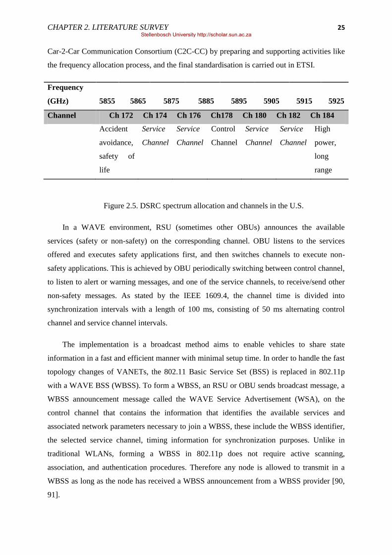
Figure 2.5, [87, 88, 89], shows the 75 MHz spectrum allocation for DSRC in the 5.9
GHz band by the U.S. FCC (Federal Communications Commission). The spectrum is divided
into seven channels each 10MHz wide; one control channel (ch178) dedicated for safety
communications only, two channels reserved for accident avoidance and high-powered public
safety (ch172, ch184), and four service channels (ch174, ch176, ch180, ch182) for both
safety and non-safety purposes. In Europe the standardisation process is mainly driven by
Stellenbosch University http://scholar.sun.ac.za
CHAPTER 2. LITERATURE SURVEY 25
Car-2-Car Communication Consortium (C2C-CC) by preparing and supporting activities like
the frequency allocation process, and the final standardisation is carried out in ETSI.
Frequency
(GHz)
5855
5865
5875
5885
5895
5905
5915
5925
Channel Ch 172 Ch 174 Ch 176 Ch178 Ch 180 Ch 182 Ch 184
Accident
avoidance,
safety of
life
Service
Channel
Service
Channel
Control
Channel
Service
Channel
Service
Channel
High
power,
long
range
Figure 2.5. DSRC spectrum allocation and channels in the U.S.
In a WAVE environment, RSU (sometimes other OBUs) announces the available
services (safety or non-safety) on the corresponding channel. OBU listens to the services
offered and executes safety applications first, and then switches channels to execute non-
safety applications. This is achieved by OBU periodically switching between control channel,
to listen to alert or warning messages, and one of the service channels, to receive/send other
non-safety messages. As stated by the IEEE 1609.4, the channel time is divided into
synchronization intervals with a length of 100 ms, consisting of 50 ms alternating control
channel and service channel intervals.
The implementation is a broadcast method aims to enable vehicles to share state
information in a fast and efficient manner with minimal setup time. In order to handle the fast
topology changes of VANETs, the 802.11 Basic Service Set (BSS) is replaced in 802.11p
with a WAVE BSS (WBSS). To form a WBSS, an RSU or OBU sends broadcast message, a
WBSS announcement message called the WAVE Service Advertisement (WSA), on the
control channel that contains the information that identifies the available services and
associated network parameters necessary to join a WBSS, these include the WBSS identifier,
the selected service channel, timing information for synchronization purposes. Unlike in
traditional WLANs, forming a WBSS in 802.11p does not require active scanning,
association, and authentication procedures. Therefore any node is allowed to transmit in a
WBSS as long as the node has received a WBSS announcement from a WBSS provider [90,
91].
Stellenbosch University http://scholar.sun.ac.za
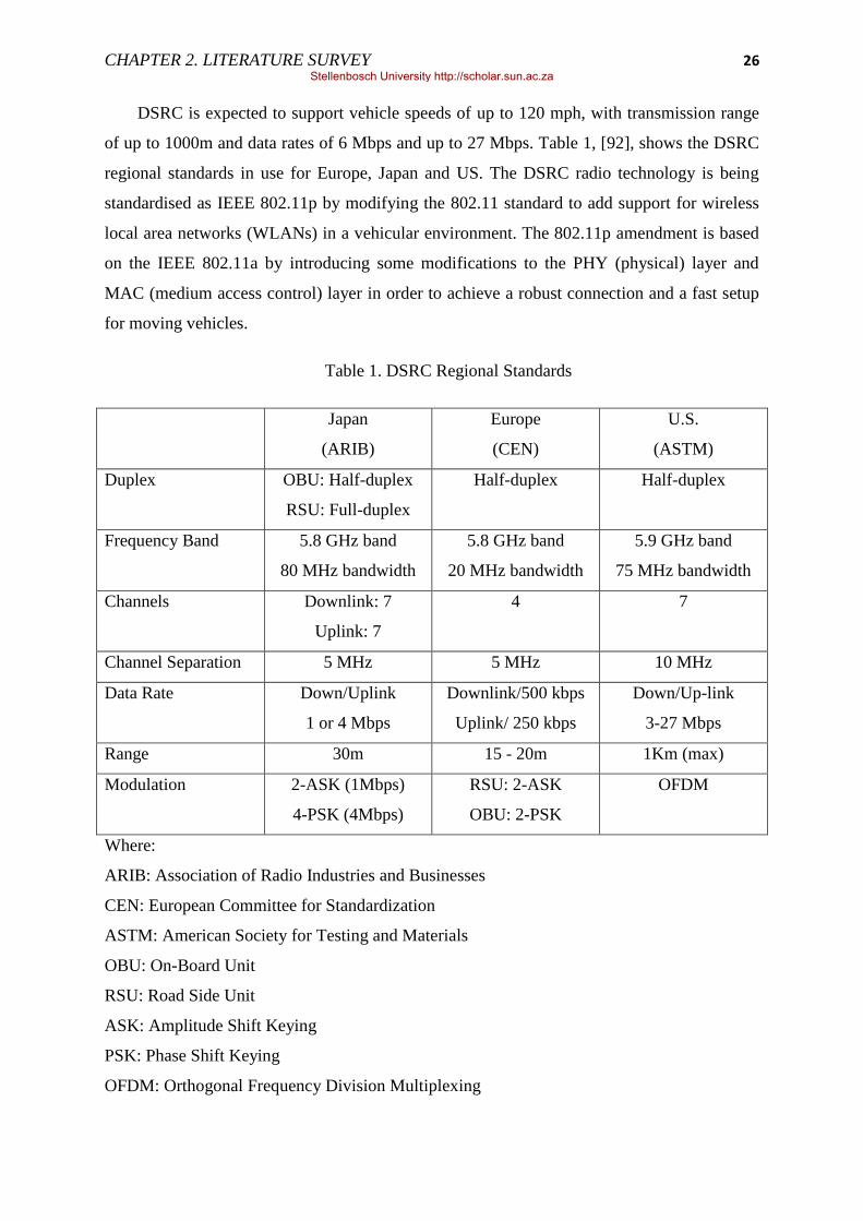
CHAPTER 2. LITERATURE SURVEY 26
DSRC is expected to support vehicle speeds of up to 120 mph, with transmission range
of up to 1000m and data rates of 6 Mbps and up to 27 Mbps. Table 1, [92], shows the DSRC
regional standards in use for Europe, Japan and US. The DSRC radio technology is being
standardised as IEEE 802.11p by modifying the 802.11 standard to add support for wireless
local area networks (WLANs) in a vehicular environment. The 802.11p amendment is based
on the IEEE 802.11a by introducing some modifications to the PHY (physical) layer and
MAC (medium access control) layer in order to achieve a robust connection and a fast setup
for moving vehicles.
Table 1. DSRC Regional Standards
Japan
(ARIB)
Europe
(CEN)
U.S.
(ASTM)
Duplex OBU: Half-duplex
RSU: Full-duplex
Half-duplex Half-duplex
Frequency Band 5.8 GHz band
80 MHz bandwidth
5.8 GHz band
20 MHz bandwidth
5.9 GHz band
75 MHz bandwidth
Channels Downlink: 7
Uplink: 7
4 7
Channel Separation 5 MHz 5 MHz 10 MHz
Data Rate Down/Uplink
1 or 4 Mbps
Downlink/500 kbps
Uplink/ 250 kbps
Down/Up-link
3-27 Mbps
Range 30m 15 - 20m 1Km (max)
Modulation 2-ASK (1Mbps)
4-PSK (4Mbps)
RSU: 2-ASK
OBU: 2-PSK
OFDM
Where:
ARIB: Association of Radio Industries and Businesses
CEN: European Committee for Standardization
ASTM: American Society for Testing and Materials
OBU: On-Board Unit
RSU: Road Side Unit
ASK: Amplitude Shift Keying
PSK: Phase Shift Keying
OFDM: Orthogonal Frequency Division Multiplexing
Stellenbosch University http://scholar.sun.ac.za

CHAPTER 2. LITERATURE SURVEY 27
The IEEE 802.11p MAC layer is designed to be PHY layer independent, and is enhanced
by the 1609.4 in the IEEE 1609 family of protocols [93] to allow for multi-channel operation
[94]. The MAC layer uses the prioritised and contention-based Enhanced Distributed Channel
Access (EDCA) scheme of 802.11e [95], which is based on the Carrier Sense Multiple
Access with Collision Avoidance (CSMA/CA) scheme [6]. In a basic EDCA access scheme,
if packets from different queues in the same station compete for the access, a virtual
resolution function will resolve the conflict by assigning the transmission opportunity to the
packet with the highest priority, while the lowest priority packet will be retransmitted or
discarded if a maximal number of retries has been reached. To cater for the multi-channel
WAVE environment, 802.11p‘s access mechanism is modified by implementing two separate
EDCA functions, one for control channel and one for service channels, each handling
different sets of queues for packets destined to be transmitted on different channel.
The 802.11p PHY layer is based on the orthogonal frequency division multiplexing
(OFDM) which is the same PHY layer used in the IEEE 802.11a standard, but with some
changes. OFDM is a special case of Frequency Division Multiplex (FDM) where the signal is
first split into independent channels, modulated by data and then re-multiplexed to create the
OFDM carrier. The changes in the IEEE 802.11p Physical Layer are shown in Table 2 where
the PHY Layer values of the 802.11a and 802.11p implementations are compared. Three
different PHY Layer modes are defined in the previous IEEE 802.11 standards, the 20 MHz,
10 MHz and 5 MHz modes. These different modes are achieved by using different sampling
(clock) rates. IEEE 802.11a usually uses the full clocked mode with 20 MHz bandwidth
while IEEE 802.11p targets the half clocked mode with 10 MHz bandwidth. The half clocked
mode in IEEE 802.11p affects the following parameters:
- Bandwidth - the 10 MHz bandwidth is used in IEEE 802.11p so as to make the
signal more robust against fading with an option of the 20 MHz bandwidth
implementation. If the optional 20 MHz channels, ch175 (combination of ch174
and 176) and ch181 (combination of ch180 and ch182) are used, data rates up to
54 Mbps can be obtained.
- Carrier spacing - the carrier spacing is reduced by ½ in IEEE 802.11p signal
compared to that of IEEE 802.11a.
Stellenbosch University http://scholar.sun.ac.za
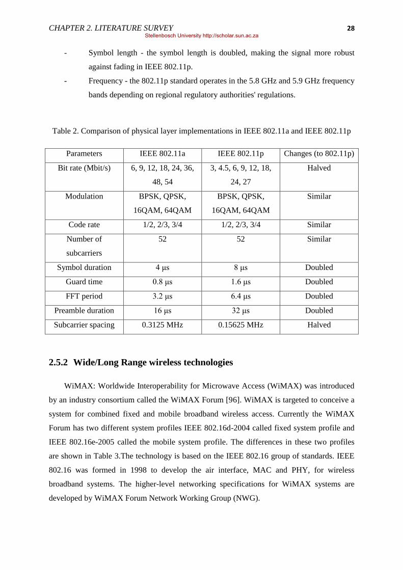
CHAPTER 2. LITERATURE SURVEY 28
- Symbol length - the symbol length is doubled, making the signal more robust
against fading in IEEE 802.11p.
- Frequency - the 802.11p standard operates in the 5.8 GHz and 5.9 GHz frequency
bands depending on regional regulatory authorities' regulations.
Table 2. Comparison of physical layer implementations in IEEE 802.11a and IEEE 802.11p
Parameters IEEE 802.11a IEEE 802.11p Changes (to 802.11p)
Bit rate (Mbit/s) 6, 9, 12, 18, 24, 36,
48, 54
3, 4.5, 6, 9, 12, 18,
24, 27
Halved
Modulation BPSK, QPSK,
16QAM, 64QAM
BPSK, QPSK,
16QAM, 64QAM
Similar
Code rate 1/2, 2/3, 3/4 1/2, 2/3, 3/4 Similar
Number of
subcarriers
52 52 Similar
Symbol duration 4 μs 8 μs Doubled
Guard time 0.8 μs 1.6 μs Doubled
FFT period 3.2 μs 6.4 μs Doubled
Preamble duration 16 μs 32 μs Doubled
Subcarrier spacing 0.3125 MHz 0.15625 MHz Halved
2.5.2 Wide/Long Range wireless technologies
WiMAX: Worldwide Interoperability for Microwave Access (WiMAX) was introduced
by an industry consortium called the WiMAX Forum [96]. WiMAX is targeted to conceive a
system for combined fixed and mobile broadband wireless access. Currently the WiMAX
Forum has two different system profiles IEEE 802.16d-2004 called fixed system profile and
IEEE 802.16e-2005 called the mobile system profile. The differences in these two profiles
are shown in Table 3.The technology is based on the IEEE 802.16 group of standards. IEEE
802.16 was formed in 1998 to develop the air interface, MAC and PHY, for wireless
broadband systems. The higher-level networking specifications for WiMAX systems are
developed by WiMAX Forum Network Working Group (NWG).
Stellenbosch University http://scholar.sun.ac.za
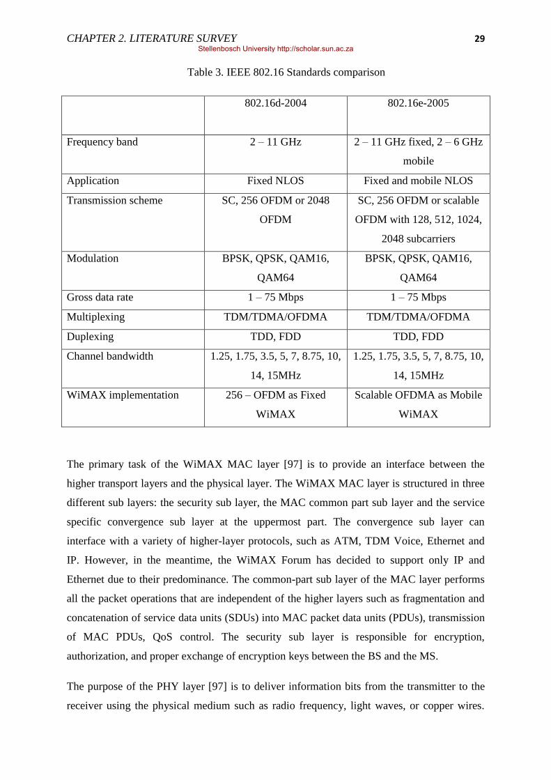
CHAPTER 2. LITERATURE SURVEY 29
Table 3. IEEE 802.16 Standards comparison
802.16d-2004 802.16e-2005
Frequency band 2 – 11 GHz 2 – 11 GHz fixed, 2 – 6 GHz
mobile
Application Fixed NLOS Fixed and mobile NLOS
Transmission scheme
SC, 256 OFDM or 2048
OFDM
SC, 256 OFDM or scalable
OFDM with 128, 512, 1024,
2048 subcarriers
Modulation
BPSK, QPSK, QAM16,
QAM64
BPSK, QPSK, QAM16,
QAM64
Gross data rate 1 – 75 Mbps 1 – 75 Mbps
Multiplexing TDM/TDMA/OFDMA TDM/TDMA/OFDMA
Duplexing TDD, FDD TDD, FDD
Channel bandwidth
1.25, 1.75, 3.5, 5, 7, 8.75, 10,
14, 15MHz
1.25, 1.75, 3.5, 5, 7, 8.75, 10,
14, 15MHz
WiMAX implementation 256 – OFDM as Fixed
WiMAX
Scalable OFDMA as Mobile
WiMAX
The primary task of the WiMAX MAC layer [97] is to provide an interface between the
higher transport layers and the physical layer. The WiMAX MAC layer is structured in three
different sub layers: the security sub layer, the MAC common part sub layer and the service
specific convergence sub layer at the uppermost part. The convergence sub layer can
interface with a variety of higher-layer protocols, such as ATM, TDM Voice, Ethernet and
IP. However, in the meantime, the WiMAX Forum has decided to support only IP and
Ethernet due to their predominance. The common-part sub layer of the MAC layer performs
all the packet operations that are independent of the higher layers such as fragmentation and
concatenation of service data units (SDUs) into MAC packet data units (PDUs), transmission
of MAC PDUs, QoS control. The security sub layer is responsible for encryption,
authorization, and proper exchange of encryption keys between the BS and the MS.
The purpose of the PHY layer [97] is to deliver information bits from the transmitter to the
receiver using the physical medium such as radio frequency, light waves, or copper wires.
Stellenbosch University http://scholar.sun.ac.za
CHAPTER 2. LITERATURE SURVEY 30
Usually, the PHY layer is not informed of quality of service (QoS) requirements and is not
aware of the nature of the application, such as VoIP, HTTP, or FTP. The PHY layer can be
viewed as a pipe responsible for information exchange over a single link between a
transmitter and a receiver.
The IEEE 802.16-2004 standard specified OFDM as the transmission method for NLOS
connections. The OFDM signal is made up of many orthogonal carriers, and each individual
carrier is digitally modulated with a relatively slow bit rate. This method has distinct
advantages in multipath propagation, since for a single carrier transmission method at the
same rate more time is needed to transmit a symbol. In case of OFDM modulation used in the
802.16 standard, the bandwidth is divided into 256 subcarriers. When pilot and null
subcarriers are removed, 192 subcarriers are left for use in carrying useful data. The capacity
of each subcarrier depends on the order of the modulation scheme used. WiMAX supports
BPSK (1 bit per subcarrier), QPSK (2 bits per subcarrier), 16QAM (4 bits per subcarrier) and
64 QAM (6 bits per subcarrier). The modulation technique is adapted to the specific
transmission requirements. Redundant bits are also carried with useful information for
purpose of error detection and correction at the receiving side. The ratio of information to
redundant bits is called coding rate and may vary from ½ to ¾. From calculated values it is
apparent that overhead introduced by the PHY layer is considerable (in most cases more than
50 %) [98].
WiMAX supports very robust data throughput; theoretical maximums could reach
approximately 75 Mbps per channel (in a 20 MHz channel using 64QAM ¾ code rate). A
number of factors affect transfer rate beyond simple radio capability, one major element
being distance from the BS. Also, the RF and physical environment play a strong role in
throughput results. The physics of frequency range also plays a powerful role in bandwidth
capability. The high frequencies provide greater bandwidths and the shorter coverage. Lower
frequencies enjoy much greater range capability, but at a cost of much lower output
bandwidth.
IEEE 802.16e-2005 [25, 100, 101, 102, 103] or mobile WiMAX is developed as an
amendment to 802.16d to support subscriber stations moving at vehicular speeds up to 120
km/h [104]. Mobile WiMAX realises the convergence of mobile and fixed broadband access
in single air interface and network architecture [105]. The IEEE 802.16e PHY layer has been
modified to scalable orthogonal frequency division multiple access (SOFDMA) for improved
Stellenbosch University http://scholar.sun.ac.za
CHAPTER 2. LITERATURE SURVEY 31
multi-path performance in non-line-of-sight conditions. The combined effort of IEEE 802.16
and the WiMAX Forum help define the end-to-end system solution for a mobile WiMAX
network. Mobile WiMAX systems are to offer scalability in both radio access technology and
network architecture. This helps in providing flexibility in network deployment options and
service offerings. WiMAX networks are designed to support a multiple set of different
applications. Some of the features supported by mobile WiMAX include, but not limited to;
high data rates, guaranteed Quality of Service (QoS), high scalability, high security and
support of high mobility. All these features enable support of different applications like
Interactive Gaming, Voice and Video Conferencing, Streaming Media, Instant Messaging &
Web Browsing, Media Content Download (Store and Forward) [104].
With the inclusion of multiple input multiple output (MIMO) antenna techniques to the PHY
layer, along with flexible sub-channelization schemes, advanced coding and modulation, high
data rates can be easily achieved. The mobile WiMAX technology can support peak
downlink (DL) data rates up to 63 Mbps per sector and peak uplink (UL) data rates up to 28
Mbps per sector in a 10 MHz channel. QoS is achieved through sub-channelization and
MAP-based signalling schemes to provide a flexible mechanism for optimal scheduling of
space, frequency and time resources over the air interface on a frame-by-frame basis. To offer
scalability, mobile WiMAX technology is designed to be able to scale to work in different
channelization from 1.25 to 20 MHz to comply with varied worldwide requirements. Mobile
WiMAX supports optimized handover schemes with latencies less than 50 milliseconds to
ensure support of real-time applications. This also makes a promising deal to work with
vehicular speeds.
The next standardization effort in which the IEEE 802 is involved in is the IEEE 802.16m
project which will support the mobility classes and scenarios supported by the IMT-
Advanced cellular systems, including high speed vehicular scenario of up to 350km or even
up to 500km/h [28, 30]. IEEE 802.16m amends the IEEE 802.16 Wireless MAN-OFDMA
specification to provide an advanced air interface. It will be designed to provide significantly
improved performance compared to other high rate broadband cellular network systems.
Cellular/LTE: there are a number of different cellular technologies such as, GSM, GPRS,
EDGE, UMTS, IS-95, CDMA2000, and EV-DO. GSM is circuit switched network developed
by ETSI as a second generation (2G) for cellular networks. It supports data communications
at the maximum rate of 9.6 kbps. GSM was then expanded to provide higher data
Stellenbosch University http://scholar.sun.ac.za

CHAPTER 2. LITERATURE SURVEY 32
communications via GPRS, 171 kbps, and later EDGE, 384 kbps. The third generation (3G),
UMTS, was then introduced by third Generation Partnership Project (3GPP) to succeed
GSM. 3G systems, UMTS/HSPA, support even higher data rates of 144 kbps, 384 kbps, and
2 Mbps under high mobility, low mobility, and stationary environments respectively. IS-95 or
cdmaOne is a 2G cellular standard developed by Qualcomm. IS-95 is now replaced by
CDMA2000 and a 3G system, CDMA2000 1xEvDO. CDMA2000 or 1xRTT provides rates
of up to 141 kbps and CDMA2000 1xEvDO (Rev. A) provides 3 Mbps and 1.8 Mbps for
down and up links respectively. The given data rates are only theoretical therefore in practice
the rates are lower. In [106], the authors have studied the behaviour of 3G, 1xEvDO, in a
vehicular environment, by testing for available upload throughput, packet round-trip-times,
and loss characteristics. They reported:
- a high average round-trip-times at around 600 ms,
- a number of short-lived disconnections where they could not transmit data, less than
30 s,
- a varying throughput and the peak upload throughput less than 140 kbps and
- no correlation between the vehicle‘s speed and the achieved throughput, but
geographic location is the dominant factor leading to variations.
Long-Term Evolution (LTE) is the new standard, in the evolution of 2G and 3G systems,
recently specified by the 3GPP on the way towards fourth-generation mobile. 3GPP radio
access network (RAN) working groups started LTE/EPC standardization in December 2004
with a feasibility study for an Evolved UMTS Terrestrial Radio Access Network (E-UTRAN)
and for the all IP-based Evolved Packet Core (EPC). LTE employs OFDMA for the RAN
downlink and SC-FDMA (Single Carrier Frequency Division Multiple Access) in the uplink.
LTE has desires to performance requirements that rely on physical layer technologies,
such as, Orthogonal Frequency Division Multiplexing (OFDM) and Multiple-Input Multiple-
Output (MIMO) systems, Smart Antennas to achieve these targets. The main objectives of
LTE are to minimize the system and User Equipment (UE) complexities, allow flexible
spectrum deployment in existing or new frequency spectrum and to enable co-existence with
other 3GPP Radio Access Technologies (RATs). E-UTRA is expected to support different
types of services including web browsing, FTP, video streaming, VoIP, online gaming, real
time video, push-to-talk and push-to-view. Therefore, LTE is being designed to be a high
data rate and low latency system as indicated by the key performance criteria. The bandwidth
Stellenbosch University http://scholar.sun.ac.za

CHAPTER 2. LITERATURE SURVEY 33
capability of a UE is expected to be 20MHz for both transmission and reception. Among
others, LTE design targets are the following.
- Support for IP-based traffic with end-to-end Quality of service (QoS).
- The system should support peak data rates of 100 Mbps in downlink and 50Mbps in
uplink within a 20MHz bandwidth
- Reduced latency to 10 ms
- Support mobility of up to 350 km/h.
- Operation in both TDD (unpaired) and FDD (paired) spectrum modes.
- Spectrum flexibility, seamless coexistence with previous technologies,
GSM/EDGE/UMTS, systems and reduced complexity and cost of the overall system.
- Supports hand-over and roaming to existing mobile networks giving the service
providers the ability to deliver a seamless mobility experience.
2.6 Approaches in Literature Survey
The most adopted vehicular networking architectures consist of road-side units (RSUs)
existing along the road and vehicle equipment called an on board unit (OBU) and application
units (AUs) executing a single or a set of applications. OBUs and RSUs form ad hoc
networks where communication takes place directly between OBUs via multi-hop or single-
hop (called V2V), or in which OBUs communicate with RSUs in order to connect to external
networks or infrastructure (called V2R or V2I) and where OBUs communicate with the RSUs
through other OBUs (called V2V2I) [4, 107, 108, 109, 35].
In [110], Tufail et al. studied the behaviour of network connections that are initiated over
an IEEE 802.11g channel from a moving car. The goal was to investigate and discuss the
possibility of using IEEE 802.11 as the protocol to establish connection between fast moving
vehicles and to understand the impact of the vehicle‘s speed. The experiment involved
measuring the amount of data transferred during the short spurts the connection was intact.
This involved two vehicles travelling in opposite directions keeping the speed constant for a
single trial but varying speed from trial to trial. The laptops were configured to operate in ad-
hoc mode and no external antennas were used. The results showed that the vehicle speed has
an impact on the data rate and connection duration (contact time). As the vehicle speed
increases the intact time decreases so does the data rate hence less data can be transferred.
They achieved a peak data rate of 7.7 Mbps at the speed of 20mph or 32km/h (relative speed
Stellenbosch University http://scholar.sun.ac.za
CHAPTER 2. LITERATURE SURVEY 34
of 40mph or 64km/h) and managed to transfer 15.1MB. At the speed of 60mph or 96km/h
(relative speed of 120mph or 193km/h), it was possible to transfer 0.3MB of data and
maintain a data rate of about 1 Mbps.
Marcelo et al. [3] had a test-bed similar to [110]. They investigated the characteristics of
links formed by in-car nodes running off-the-shelf wireless technologies. The two wireless
technologies were IEEE 802.11a and IEEE 802.11g and were configured to operate in ad hoc
mode. They also included the impact of transport protocols (TCP and UDP) and packet size
on the amount of data transferred. The car speed was varied from 20km/h to 60km/h (relative
speed of 40km/h to 120km/h), while the packet sizes tested were 150, 500 and 1460 bytes for
both TCP and UDP. The results show that using TCP instead of UDP reduces the average
total amount of data transferred, and as speed increased no data was received due to the long
time TCP spends trying to establish a connection. They also showed that higher frequency
5.15GHz IEEE 802.11a is more prone to propagation problems (diffraction, reflection, and
absorption) than lower frequency IEEE 802.11g which lead to shorter contact time. Again
they showed a trade-off between speed and packet size; decreasing the packet size reduced
the capacity loss and increased the capacity as speed increased.
Wellens et al. [111] investigated the one hop performance of IEEE 802.11a/b/g for car to
car (C2C) and car to roadside (C2R) scenarios. They had one node operating as an access
point (AP) while the other was in normal configuration. For C2R measurements they placed
the AP in the middle of a 2km road while a car connects to it as it passes by. The external
antennas with 5 dBi gain were used to provide line of sight. Both UDP and TCP traffic with
different packet sizes were generated to evaluate their effect at vehicular speeds and these
were compared with the static measurement values performed in the lab where the distance
between AP and client node was 1m. The tests were conducted under urban scenario with the
presence of traffic and tall buildings and on a highway. Throughput, signal to noise ratio
(SNR) and frame error rate were tracked in these experiments. They found throughput at
120km/h to be slightly lower than that of static case and larger packets presented a worse
reception compared to smaller packets. The communication range was also found to be larger
when using lower physical layer rates due to the use of less aggressive coding and
modulation schemes. Speed did not affect the performance of Wi-Fi but distance and
availability of line of site did create a negative impact.
Stellenbosch University http://scholar.sun.ac.za

CHAPTER 2. LITERATURE SURVEY 35
Chou et al. [112] studied the feasibility of using fixed WiMAX (IEEE 802.16d) for V2I
communication in comparison with Wi-Fi (IEEE 802.11g). The measurements focused on
throughput, latency and packet loss. For WiMAX two modulation modes, BPSK ½ and
64QAM ¾ were studied. They found that even though they managed to achieve data transfers
at long ranges with WiMAX, with Wi-Fi one can get higher throughput and a shorter latency
at shorter distances. Frame duration also seemed to be a major factor in WiMAX; as the
frame duration increased, round trip time also increased hence increasing latency. They also
found that larger frame sizes offer better throughput but at a cost of longer delays hence they
are more suitable for delay tolerant applications. The same study was conducted on QualNet
4.5 simulation tool by Msadaa et al. [113] but instead they used IEEE 802.11p and mobile
WiMAX (IEEE 802.16e). They evaluated the performance for different vehicle speed, data
rates and network deployments. They also showed that mobile WiMAX suffers longer delays
compared to IEEE 802.11p and the average throughput does not depend on the vehicle speed.
Miller [4] presented a V2V2I architecture which combines V2V and V2I architectures
whereby vehicles form zones and one is selected as a super node using a proposed super
vehicle detection algorithm. The super node collects data from vehicle in its zone and sends it
to the roadside server. The analysis is performed using a FreeSim simulation tool. The same
approach is performed by Benslimane et al. [114] where they proposed and simulated on NS2
an integrated VANET - 3G network architecture where they created dynamic vehicle clusters.
Within each cluster all vehicles were equipped with IEEE 802.11p interfaces while some
vehicles were equipped with extra UTRAN interfaces to act as gateways to link VANET to
UMTS. Gateway selection and clustering are performed based on route stability, mobility and
signal strength through a proposed dynamic clustering and gateway management algorithms
implemented on top of routing protocol. The aim was to reduce frequent handoffs at base
stations and decrease bottlenecks and congestion across path towards a gateway; also to allow
vehicles without 3G to access UMTS network. They evaluated the performance based on data
packet delivery ratio, throughput, packet drop and delay. They implemented their proposed
algorithm on top of AODV protocol in comparison with Multi-metric Gateway Selection
Algorithm (MGSA). They achieved better data packet delivery ratios and higher throughput
in comparison.
J. Eriksson et al. [115] designed, implemented and experimented evaluation of Cabernet
Transport Protocol (CTP), a content delivery network for vehicles moving in and around
Stellenbosch University http://scholar.sun.ac.za

CHAPTER 2. LITERATURE SURVEY 36
cities. Cabernet delivers data to and from cars using open IEEE 802.11b/g access points
(APs) that the cars connect to opportunistically while they pass by. The primary goal of CTP
was to develop techniques that allow moving cars to obtain high data transfer throughput
through these APs. The system was deployed in 10 taxis running in the Boston area. The
nodes/vehicles were running QuickWiFi and the system running CTP. QuickWiFi was used
to reduce connection establishment time. They showed that QuickWiFi was able to connect in
366 ms on average. Also shown was the ability of CTP to achieve double the throughput of
TCP over paths with high non-congestion losses with a mean throughput of 800 kbps when
connectivity is present and in an end-to-end performance evaluation, Cabernet was able to
achieve an end-to-end throughput of 38 megabytes/hour (86.5 kbps) per car during its drive.
M. Aguado et al. [104] presented a mobile WiMAX network deployment as a candidate
for broadband and low latency V2I communication architecture. The authors presented and
evaluated the performance of a mobile WiMAX network architecture deployment in two
highly demanding V2I scenarios;
i the two mobile nodes supporting real-time applications crossing during handover case
varying their speeds from 100 km/h to 160 km/h and
ii a heavy loaded scenario with forty (40) mobile nodes initially attached to the same
base station and support the same real time application with the traffic centre.
The evaluation scenario was built using the Opnet Beta WiMAX model (Feb 2008
release). For the first test, they showed a drop in the data traffic when the two mobile nodes
cross each other during the handover process. They also showed that it is possible in some
cases that handover is higher than the expected 50ms delay value but the number of these
events is low and does not compromise the average value obtained. As for the second test, the
end-to-end delay increases but still met the WiMAX radio system profile requirements.
Stellenbosch University http://scholar.sun.ac.za

37
Chapter 3 Experimental Setup
This work evaluates a system that uses a combination of WiMAX and Wi-Fi to
respectively provide V2I and V2V connectivity in a V2V2I vehicular network. To ensure the
validity of vehicular network, a proper data exchange between node members of a network
requires, among other characteristics, the inclusion of node mobility under different
environmental conditions. The experiment consists of two vehicles (mobile nodes) that are
linked with an ad-hoc Wi-Fi connection and a stationary base station with a dedicated
WiMAX connection to one of the vehicles. Wi-Fi ad-hoc mode allows the devices to
communicate with each other without the use of access point (AP), and all devices in range
connect in a peer-to-peer fashion. WiMAX was chosen because the wide coverage it offers
and Wi-Fi because of its availability and resemblance to the upcoming IEEE 802.11p
standard developed specially for use in VANETs.
The experimental setup was designed to accurately reflect conditions present in an
urbanised environment. In a real world scenario, vehicles come in contact with each other in
different ways, by moving either perpendicular or parallel to each other [116]. The
perpendicular movement can happen when both vehicles approach or leave an intersection
and when one vehicle approaches while the other leaves an intersection. The parallel
movement happens when vehicles travel in the same direction following each other or when
they travel in opposite direction to each other. In all these cases the contact time is either long
lived or short lived. These scenarios are represented in this research, the long lived contact,
by allowing vehicles to travel in the same direction following each other, and the short lived
contact by travelling in opposite directions. This helps in determining the kind of applications
that can be supported as it gives an indication of how much data can be transferred in the best
and worst case scenarios.
Since the experiment concurrently uses two different wireless technologies (Wi-Fi and
WiMAX), initial tests were performed to characterise the individual performance of each
technology before combining the two. This approach ensures that each part of the system is
functional before integrating the full experiment, but also provides clues as to how each of
the components impact system performance. Therefore Wi-Fi and WiMAX performance
were first evaluated separately. The experiment was then divided into four sets:
Stellenbosch University http://scholar.sun.ac.za

CHAPTER 3. EXPERIMENTAL SETUP 38
(i) vehicle-to-roadside communication architecture, V2R, using Wi-Fi,
(ii) vehicle-to-vehicle communication architecture, V2V, also using Wi-Fi,
(iii) vehicle-to-infrastructure communication architecture, V2I, using WiMAX and,
(iv) vehicle-to-vehicle-to-infrastructure communication architecture, using Wi-Fi and
WiMAX.
The first set of experiments was conducted separately from others on an open space
outside Stellenbosch University campus where there is less traffic and signal interference is
low, as illustrated by Figure 3.1. The IEEE 802.11g was used on this route and the
communication range was found to be around 180 m. This was determined by fixing the
roadside node at the centre of the road (point X) and slowly moving the mobile node away
and towards it. When moving away and or towards the fixed node, the positions where the
link was lost and established were respectively marked, providing the communication range.
The procedure was repeated on either sides of the fixed node. Therefore the start/end of
communication range were marked point A and B. These points were then chosen to be
approximately 400 m apart, allowing the stationary node, point X, to be placed 200 m from
each point, well off the communication range.
Figure 3.1. Open space for V2R experiments using Wi-Fi (802.11g)
Stellenbosch University http://scholar.sun.ac.za
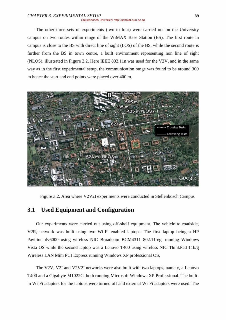
CHAPTER 3. EXPERIMENTAL SETUP 39
The other three sets of experiments (two to four) were carried out on the University
campus on two routes within range of the WiMAX Base Station (BS). The first route in
campus is close to the BS with direct line of sight (LOS) of the BS, while the second route is
further from the BS in town centre, a built environment representing non line of sight
(NLOS), illustrated in Figure 3.2. Here IEEE 802.11n was used for the V2V, and in the same
way as in the first experimental setup, the communication range was found to be around 300
m hence the start and end points were placed over 400 m.
Figure 3.2. Area where V2V2I experiments were conducted in Stellenbosch Campus
3.1 Used Equipment and Configuration
Our experiments were carried out using off-shelf equipment. The vehicle to roadside,
V2R, network was built using two Wi-Fi enabled laptops. The first laptop being a HP
Pavilion dv6000 using wireless NIC Broadcom BCM4311 802.11b/g, running Windows
Vista OS while the second laptop was a Lenovo T400 using wireless NIC ThinkPad 11b/g
Wireless LAN Mini PCI Express running Windows XP professional OS.
The V2V, V2I and V2V2I networks were also built with two laptops, namely, a Lenovo
T400 and a Gigabyte M1022C, both running Microsoft Windows XP Professional. The built-
in Wi-Fi adapters for the laptops were turned off and external Wi-Fi adapters were used. The
Stellenbosch University http://scholar.sun.ac.za

CHAPTER 3. EXPERIMENTAL SETUP 40
adapters were mounted outside the vehicles to increase coverage. The WiMAX subscriber
unit (SU) was placed in one of the vehicles and a WiMAX base station was mounted on top
of a five storey building (indicated with B in Figure 3.2). In addition both the vehicles were
equipped with GPS dongles to monitor the position and speed of the vehicles.
Speed (absolute and relative vehicle speed), separation (between vehicles and from BS),
signal strength (WiMAX and Wi-Fi), modulation type (WiMAX and Wi-Fi), throughput, data
transferred, contact time (time from first packet to last packet received) and jitter were
recorded for each of the experiments conducted. Speed and position were recorded on each
node while the Wi-Fi RSSI and modulation type, throughput, data transferred, jitter and
contact time were recorded on the server node. The WiMAX RSSI and modulation type were
recorded on the base station‘s PC. Table 4 provides a list of what was logged and calculated
with respect to different VANET architectures.
Table 4. Results logged and calculated for each communication architecture
Logged
V2V V2I V2V2I
Following Crossing LOS NLOS Following Crossing
LOS NLOS LOS NLOS
Position (Coordinates) √ √ √ √ √ √ √ √
Absolute Speed √ √ √ √ √ √ √ √
RSSI Wi-Fi √ √ - - √ √ √ √
WiMAX - - √ √ √ √ √ √
Throughput Wi-Fi √ √ - - √ √ √ √
WiMAX - - √ √
Data Transferred √ √ √ √ √ √ √ √
Jitter √ √ √ √ √ √ √ √
Cal
cula
ted
Separation Vehicles √ √ - - √ √ √ √
BS - - √ √ √ √ √ √
Relative Speed - √ - - - - √ √
Cumulative Data
Transferred
√ √ √ √ √ √ √ √
Contact Time √ √ √ √ √ √ √ √
Stellenbosch University http://scholar.sun.ac.za

CHAPTER 3. EXPERIMENTAL SETUP 41
3.1.1 Wi-Fi Configuration
Wi-Fi ad-hoc network or Independent Basic Service Set (IBSS) was used in this setup
because future vehicular networks are expected to operate in this fashion. In this mode the
devices communicate directly with each other in a peer-to-peer fashion. The major setback in
ad-hoc mode is, as the number of devices grows the performance of the network decreases.
But for this experiment only two nodes are allowed to communicate. All the wireless adapters
in an ad-hoc network are expected to use the same SSID and channel number. Because Wi-Fi
operates on an unlicensed frequency band of 2.4GHz it is likely to get interference not only
from other Wi-Fi devices but from other devices like Bluetooth, TV remote controls, which
also use the same frequency band. But with a careful configuration, the overall interference
can be minimised. In this experiment channel 1 was selected mainly because it has the least
number of channels (other Wi-Fi channels) interfering with it: the lower the interference the
higher the throughput hence improved system performance.
To reduce connection time and speed up data exchange, the use of static IP address was
employed while open authentication was used and allowed to send unencrypted data. The
transmit power in our system was set to automatic to incorporate mobility, allowing the
devices to adjust the power levels accordingly based on the distance between the nodes.
In [3] the authors showed that when compared to IEEE 802.11g, IEEE 802.11a gives a
poor performance. The overall transmission range was shorter leading to short contact time
and less data successfully transferred. For this reason, in this research IEEE 802.11g was
selected for V2R communication architecture, where the laptops‘ built-in Wi-Fi cards were
used. On the other hand, to increase the communication range, in the V2V and V2V2I
communication architectures, the built-in WLAN devices were switched off on both laptops.
Instead EDiMAX EW-7711USn USB adapters [117] with omnidirectional 3dBi gain
detachable antennas were used. This Wi-Fi adapter supports the IEEE 802.11b/g/n standards.
In this part of experiment IEEE 802.11n was chosen for its higher data rates. The Windows
wireless zero configuration utility was also disabled and Edimax wireless configuration
utility, EZmax, was used to control and configure the wireless adapter. The configuration
parameters used for Wi-Fi are shown in Table 5.
Stellenbosch University http://scholar.sun.ac.za
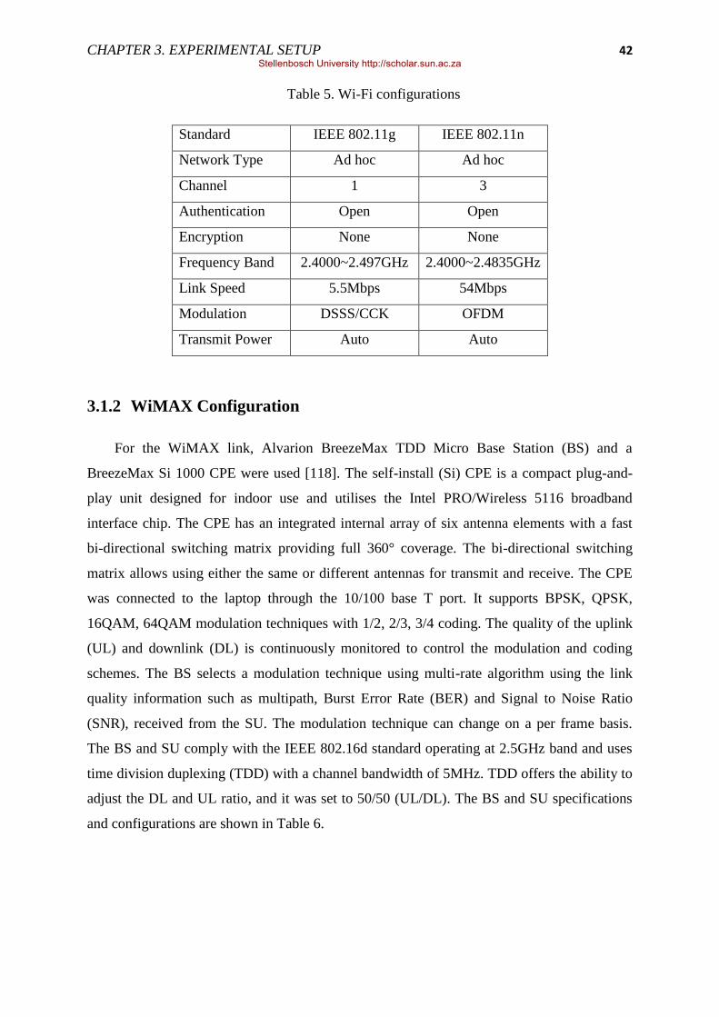
CHAPTER 3. EXPERIMENTAL SETUP 42
Table 5. Wi-Fi configurations
Standard IEEE 802.11g IEEE 802.11n
Network Type Ad hoc Ad hoc
Channel 1 3
Authentication Open Open
Encryption None None
Frequency Band 2.4000~2.497GHz 2.4000~2.4835GHz
Link Speed 5.5Mbps 54Mbps
Modulation DSSS/CCK OFDM
Transmit Power Auto Auto
3.1.2 WiMAX Configuration
For the WiMAX link, Alvarion BreezeMax TDD Micro Base Station (BS) and a
BreezeMax Si 1000 CPE were used [118]. The self-install (Si) CPE is a compact plug-and-
play unit designed for indoor use and utilises the Intel PRO/Wireless 5116 broadband
interface chip. The CPE has an integrated internal array of six antenna elements with a fast
bi-directional switching matrix providing full 360° coverage. The bi-directional switching
matrix allows using either the same or different antennas for transmit and receive. The CPE
was connected to the laptop through the 10/100 base T port. It supports BPSK, QPSK,
16QAM, 64QAM modulation techniques with 1/2, 2/3, 3/4 coding. The quality of the uplink
(UL) and downlink (DL) is continuously monitored to control the modulation and coding
schemes. The BS selects a modulation technique using multi-rate algorithm using the link
quality information such as multipath, Burst Error Rate (BER) and Signal to Noise Ratio
(SNR), received from the SU. The modulation technique can change on a per frame basis.
The BS and SU comply with the IEEE 802.16d standard operating at 2.5GHz band and uses
time division duplexing (TDD) with a channel bandwidth of 5MHz. TDD offers the ability to
adjust the DL and UL ratio, and it was set to 50/50 (UL/DL). The BS and SU specifications
and configurations are shown in Table 6.
Stellenbosch University http://scholar.sun.ac.za

CHAPTER 3. EXPERIMENTAL SETUP 43
Table 6. IEEE 802.16-2004 (Fixed WiMAX) configurations
Frequency Band 2.496 – 2.690 GHz
Transmission Scheme 256 OFDM
Modulation Downlink: OFDM, Uplink: OFDMA-16
BPSK, QPSK, QAM16, QAM64
FEC Convolutional Coding: ½, 2/3, ¾
Operation Duplex Mode TDD
Duplex UL/DL Ratio (%) 50/50
Channel Bandwidth 5MHz
Transmit Power Auto
Antenna Height (m) 30
3.1.3 Network Monitoring Tools
The network performance was monitored with Iperf [119] which uses a client server
approach, whereby one node sends network traffic (client) and the other node receives the
network traffic (server). For V2V communication one of the nodes ran Iperf in a server mode
while the other in a client mode. For V2I communication a node acted as a server while a PC
with a LAN connection to the WiMAX BS acted as a client. For the complete V2V2I
communication we had the same configuration as in V2I communication except the server
node was now connected to the bridge node using Wi-Fi. In all the cases, UDP traffic was
generated using Iperf, which also measures throughput, data transferred and jitter. A script
was used to read and record the received signal strength indicator (RSSI) reported by the Wi-
Fi card driver from one of the laptops. Another script on a PC at the BS was used to record
the WiMAX RSSI reported by the BS access unit. The Iperf default settings were adopted
where the client periodically sends 1470byte UDP datagram to the server. Net meter [120], a
network traffic monitor, was used to verify the results reported by Iperf.
The UDP protocol was chosen because of the inability of the TCP protocol to efficiently
manage the effects of mobility in mobile ad hoc networks [121, 122, 123, 124, 125, 126,
127]. Station movements may cause route failures and route changes and, hence, packet
losses and delayed ACKs. The TCP misinterprets these events as congestion signals and
activates the congestion control mechanism. These lead to unnecessary retransmissions and
Stellenbosch University http://scholar.sun.ac.za

CHAPTER 3. EXPERIMENTAL SETUP 44
throughput degradation. In addition, node mobility may aggravate the unfairness between
competitive TCP sessions [128].
3.2 Experimental Approach
3.2.1 Wi-Fi Only Tests (V2R and V2V)
For Wi-Fi only communication (V2V), three tests were carried out:
(i) vehicles following each other on the routes,
(ii) vehicles crossing each other (from opposite directions) on the routes, and
(iii) vehicle sending/receiving data to/from a stationary node on a roadside.
The tests are depicted in Figure 3.3 (a), (b) and (c) respectively. For V2R experiments, to
investigate the effect of node mobility on Wi-Fi, different relative vehicle speeds were
considered; 40 km/h, 50 km/h, 60 km/h, 80 km/h and 90 km/h. Because the effect of
mobility is of interest here, keeping the vehicle speed constant while in range was crucial to
allow for easy calculation of relative speed. Hence it was made sure that when the node
reaches either starting or ending point (point A or B in Figure 3.1), the node is already at the
required speed until it reached the other point.
Knowing the behaviour of Wi-Fi under different vehicular speeds (from V2R
experiments), V2V looked at how much data can be transferred using Wi-Fi at different
vehicular behaviours under different environmental conditions. Here the individual vehicle
speed was kept below the legal speed limit of 60 km/h. An additional test was also performed
where the two vehicles were following each other for 50 km on a highway route with speeds
up to 120km/h and the separation kept below about 100 metres.
(a) V2V vehicles following (b) V2V vehicles crossing
Wi-Fi
Wi-Fi
Stellenbosch University http://scholar.sun.ac.za

CHAPTER 3. EXPERIMENTAL SETUP 45
(c) Vehicle and a Roadside Unit (RSU)
Figure 3.3. Initial V2V performance tests using Wi-Fi
3.2.2 WiMAX Only Tests (V2I)
For WiMAX only communication (V2I), the WiMAX enabled vehicle was driven along
both routes, Figure 3.4. This enabled us to seamlessly integrate the two technologies and test
with one of the nodes configured as a network bridge connected to the other node using Wi-
Fi and to the infrastructure (BS) using WiMAX.
Figure 3.4. V2I performance tests using WiMAX
3.2.3 Wi-Fi and WiMAX (V2V2I)
For the complete experiment using V2V2I communication, the two tests, following and
crossing, were repeated on both routes as shown in Figure 3.5.
Wi-Fi
RSU
WiMAX
Stellenbosch University http://scholar.sun.ac.za

CHAPTER 3. EXPERIMENTAL SETUP 46
(a) V2V2I setup for vehicles crossing (b) V2V2I setup for vehicles following
Figure 3.5. V2V2I tests using combination of Wi-Fi and WiMAX
3.2.4 Live Audio and Video Streaming
In addition to the quantitative link performance results, the V2I and V2V2I configuration
was also used to qualitatively evaluate the link using video and audio streaming from the base
station to both vehicles. A live video from a TV channel was streamed over WiMAX using
an open source multimedia player called videoLAN (VLC). VLC was configured to stream
the video in H.264/AVI or MPEG-4 encoding format and the audio stream was encoded in
AAC. The video bit rate configuration was 300 kbps, 15 fps and the audio bit rate was 96
kbps.
Wi-Fi
WiMAX
Wi-Fi
WiMAX
Stellenbosch University http://scholar.sun.ac.za

47
Chapter 4 Results and Discussion
In this research we evaluated the performance of Wi-Fi (IEEE 802.11 g/n) and WiMAX
(IEEE 802.16d) for different VANET architectures based on measurements of contact time,
throughput/data rate, received signal strength, jitter, and total data transferred. Signal
strength, herein referred to as received signal strength indicator (RSSI) is measured in
decibels given in relation to one milliwatt (dBm). Throughput is a measure of the amount of
packets that can be transmitted at a given amount of time measured in kilobits per second
(kbps) or Megabits per second (Mbps). Jitter is the delay variation in packets measured in
milliseconds (ms) and total data transferred represents the data bytes (B) that are correctly
received on the server side and with an acknowledgment correctly received on the client.
Line-of-sight (LOS) was always maintained for pure V2V communication because of the
usage of short range Wi-Fi, while V2I communication was operated under LOS as well as
non-LOS (NLOS) conditions. V2V2I communication utilised both Wi-Fi and WiMAX hence
it also operated under LOS and NLOS conditions. When this paper refers to LOS and NLOS
we therefore refer to WiMAX line-of-sight or non-line-of-sight.
The experimental results are graphically presented on time based plots, with time
increasing to the right. In order to capture significance of physical separation, the labels
presented on the horizontal axes are separation at the time, rather than the time.
4.1 Vehicle to Roadside (Wi-Fi - IEEE802.11g)
Figure 4.1 shows the measured throughput as a function of distance from the results
obtained when a car was moving at 60km/h. As the mobile node approaches or leaves the
stationary node, throughput rapidly increases and decreases respectively at around a range of
100 m and the peak throughput is reached within that radius. This change is also visible in
Figure 4.2 where the signal strength begins to increase from the same range of around 100m.
Also visible from the figures is even when the two nodes are crossing each other; the
throughput and the signal strength seem to drop slightly. This behaviour is caused by the
power management techniques [24]. As the nodes approach each other, they tend to decrease
the transmission power, and as they separate they increase the power to try and keep the
connection until the maximum power level is reached and the link is lost.
Stellenbosch University http://scholar.sun.ac.za

CHAPTER 4. RESULTS AND DISCUSSION 48
Figure 4.1. Average throughput as the car travels at 60km/h
Figure 4.2. Average signal strength as the car travels at 60km/h
Figure 4.3 shows the average total data transferred, average throughput and average
contact time (time taken for a connection) between the two nodes while moving at different
speeds. From the graph, it can be seen that as the speed increases, as expected the connection
time decreases hence also a decrease in total data transferred. The interesting part to be noted
here is the behaviour of the throughput; it does not follow the node‘s speed. As an example,
the throughput when the speed is 40 km/h is lower than when the speed is 60 km/h and even
lower at 90 km/h hence showing it does not increase or decrease with speed. This goes in-line
with the conclusion in [24], namely that one of the requirements of IEEE 802.11 is to support
0
1
2
3
4
-200 -150 -100 -50 0 50 100 150 200
Thro
ugh
pu
t (M
bp
s)
Distance (m)
-100
-90
-80
-70
-60
-50
-200 -150 -100 -50 0 50 100 150
Sign
al S
tre
ngt
h (
dB
m)
Distance (m)
Stellenbosch University http://scholar.sun.ac.za

CHAPTER 4. RESULTS AND DISCUSSION 49
both mobile as well as portable stations. It is further explained that since each RF component
follows its own distinct path, there will be differences in travel times and RF wave geometry;
initially a uniform RF wave leaves the transmitting antenna, as the wave traverses space, it
may encounter obstacles that alter the original wave or create new RF signals. One or more
components of the original RF wave may continue travelling straight to the receiving
antenna; other components may diffract, scatter, or reflect off of obstructions. These
propagation effects blur the distinction between portable and mobile stations making
stationary stations to often appear to be mobile.
Figure 4.3. Overall performance of IEEE 802.11g in V2R at vehicular speeds
Figure 4.4 shows a plot of the signal strength for all the tests performed at different
vehicular speeds. Again the signal strength on all the cases does not change with speed, but
rather with the separation of the nodes. Figure 4.5 shows a plot of throughput as speed
changes. The throughput behaviour, as expected, follows that of the signal strength whereby
the data is transmitted when the two nodes are in range. Again as the signal gets stronger the
throughput also increases.
8.6 6.24 5.61
3.63 3.22 2.35 2.43 2.49 2.29 2.03
30
22 20
14 13
0
5
10
15
20
25
30
35
40 50 60 80 90
Speed (km/h)
Avg. Data Transferred(MB) Average Throughput(Mbps) Avg. Connection Time(s)
Stellenbosch University http://scholar.sun.ac.za

CHAPTER 4. RESULTS AND DISCUSSION 50
Figure 4.4. Signal strength received for different vehicular speeds
Figure 4.5. Throughput measured for different vehicular speeds
4.2 Vehicle to Vehicle communication (Wi-Fi - IEEE802.11n)
4.2.1 Vehicles following each other
Figure 4.6 shows, for a representative 100 s, the throughput and signal strength with
respect to separation (on time-based axis) between the two vehicles following each other. The
test was conducted on a highway with a measured average absolute vehicle speed of 113
km/h. The average results recorded for the tests are separation of 34 m, throughput of 31.3
-100
-90
-80
-70
-60
-50
-200 -150 -100 -50 0 50 100 150 200
RSS
I (d
Bm
)
Distance (m)
40km/h 50km/h 60km/h 80km/h 90km/h
0
1
2
3
4
5
-200 -150 -100 -50 0 50 100 150 200
Thro
ugh
pu
t (M
bp
s)
Distance (m)
40km/h 50km/h 60km/h 80km/h 90km/h
Stellenbosch University http://scholar.sun.ac.za

CHAPTER 4. RESULTS AND DISCUSSION 51
Mbps, and average jitter of 0.38 ms. A total of 386.3 MB of data was transferred in a 100
seconds period. The maximum peak data rate recorded was 34.5Mbps occurring at random
points in the test. For the full test, which lasted 20 minutes, 4.4 GB were transmitted from
one car to the other. The similar results were obtained when the setup was conducted in an
urban environment.
At various stages of the experiment there were obstacles (other vehicles) in-between the
two communicating vehicles. This is visible from the graph where the throughput increases
and decreases sharply. Since the radio was set to automatically adjust the transmit power, the
radio would automatically adjust the power level when the link became weak. The variation
in signal strength was therefore additionally affected by the increase in transmission power of
the Wi-Fi card.
Figure 4.6. V2V communication for vehicles following
4.2.2 Vehicles moving in opposite directions
Figure 4.7 shows a graph of the two vehicles travelling in opposite directions at an
average relative speed of 64 km/h in an urban area. The average contact time recorded was 33
s and the average communication range was found to be 302 m with an average throughput of
13.7 Mbps per test run taken over the period of established contact, average jitter of 1.88 ms
and an average of 51.7 MB data transferred. The maximum peak data rate of 31.7 Mbps was
-100
-95
-90
-85
-80
-75
-70
-65
-60
-55
-50
0
5
10
15
20
25
30
35
40
30
36
42
40
34
32
34
37
38
36
32
34
34
30
31
35
32
32
33
28
26
RSS
I (d
Bm
)
Thro
ugh
pu
t (M
bp
s)
Separation between vehicles (m)
Throughput (Mbps) RSSI(dBm)
Stellenbosch University http://scholar.sun.ac.za

CHAPTER 4. RESULTS AND DISCUSSION 52
reached with the vehicles 0 m from each other i.e. at the point of crossing. The plot shows the
throughput and signal strength with respect to separation between the two vehicles.
From the figure, the Wi-Fi‘s data rate seems to indicate a dependence on signal strength
which is in turn affected by the separation between the two vehicles. The same behaviour is
also reported in [3, 111, 112], as the two communicating nodes come closer, the signal
strength increases, and so does the data rate.
Figure 4.7. V2V communication for vehicles crossing
4.3 Vehicle to Infrastructure communication (WiMAX -
IEEE802.16d-2004)
The WiMAX throughput and signal strength in the V2I scenario for LOS and NLOS
environments are shown in Figure 4.8 and Figure 4.9 respectively. The results represent a
representative test run that lasted for 100 seconds. The WiMAX data rate drops from around
5 Mbps to around 500 kbps as soon as the vehicle becomes mobile. We determined that the
cause of this to be modulation change from 64QAM to either BPSK or QPSK caused by
increased BER.
-100
-95
-90
-85
-80
-75
-70
-65
-60
-55
-50
0
5
10
15
20
25
30
35
40
289 250 220 192 164 130 89 44 3 38 82 131 176 213 240 270 302
RSS
I (d
Bm
)
Thro
ugh
pu
t (M
bp
s)
Separation between vehicles (m)
Throughput (Mbps) RSSI(dBm)
Stellenbosch University http://scholar.sun.ac.za

CHAPTER 4. RESULTS AND DISCUSSION 53
4.3.1 Vehicle on LOS route
The average vehicle speed was 31km/h and a total data transfer of 6.35 MB at an
average data rate of 521 kbps with an average jitter of 8.22 ms.
Figure 4.8. V2I communication in LOS condition
4.3.2 Vehicle on NLOS route
The average vehicle speed was 33 km/h. The average data rate of 518 kbps was reached
and produced a total data transfer of 6.33 MB with an average jitter of 8.56 ms.
Figure 4.9. V2I communication in NLOS condition
-100
-80
-60
-40
-20
0
0
100
200
300
400
500
600
700
244
259
280
294
311
338
368
385
403
436
472
504
520
538
558
573
RSSI
(dB
m)
Thro
ughp
ut (
kbps
)
Separation between vehicle and BS (m)
Throughput (kbps) RSSI(dBm)
-100
-80
-60
-40
-20
0
0
100
200
300
400
500
600
700
929
936
935
934
936
940
941
934
903
856
804
755
726
700
664
648
RSSI
(dB
m)
Thro
ughp
ut (
kbps
)
Separation between vehicle and BS (m)
Throughput (kbps) RSSI(dBm)
Stellenbosch University http://scholar.sun.ac.za

CHAPTER 4. RESULTS AND DISCUSSION 54
The NLOS signal strength is weaker than that of LOS test due to the distance from the
base station and the presence of obstacles that affect the signal. This can also be seen from
the data rate plot: Even though the data rate peaks at about the same value as in LOS
conditions, in NLOS the fluctuation is higher and the data rate drops too close to zero.
4.4 Vehicle to Vehicle to Infrastructure communication (Wi-Fi -
IEEE802.11n and WiMAX -IEEE802.16d)
4.4.1 Vehicles following each other
Figure 4.10 shows the throughput and signal strength for vehicles following each other
in an urban environment under LOS, and for NLOS in Figure 4.11. The average link
throughput for LOS and NLOS in the V2I only tests is also shown for reference.
4.4.1.1 WiMAX vehicle on LOS route
The graph shows a noticeable increase in data rate at an intersection where the vehicles
had to stop. The temporary cessation has this effect on the throughput due to the lower
WiMAX BER. This event is followed by data rate decrease as the distance between the
vehicles increased to 150m with respect to the second vehicle still at the intersection. But the
throughput settles to the same value as that of V2I average, showing the performance
dependence on WiMAX.
The average absolute vehicle speed was 27 km/h with an average vehicle separation of
31 m. This resulted in an average data rate of 539 kbps and total data transfer of 6.64 MB in
the 100 seconds period.
Stellenbosch University http://scholar.sun.ac.za
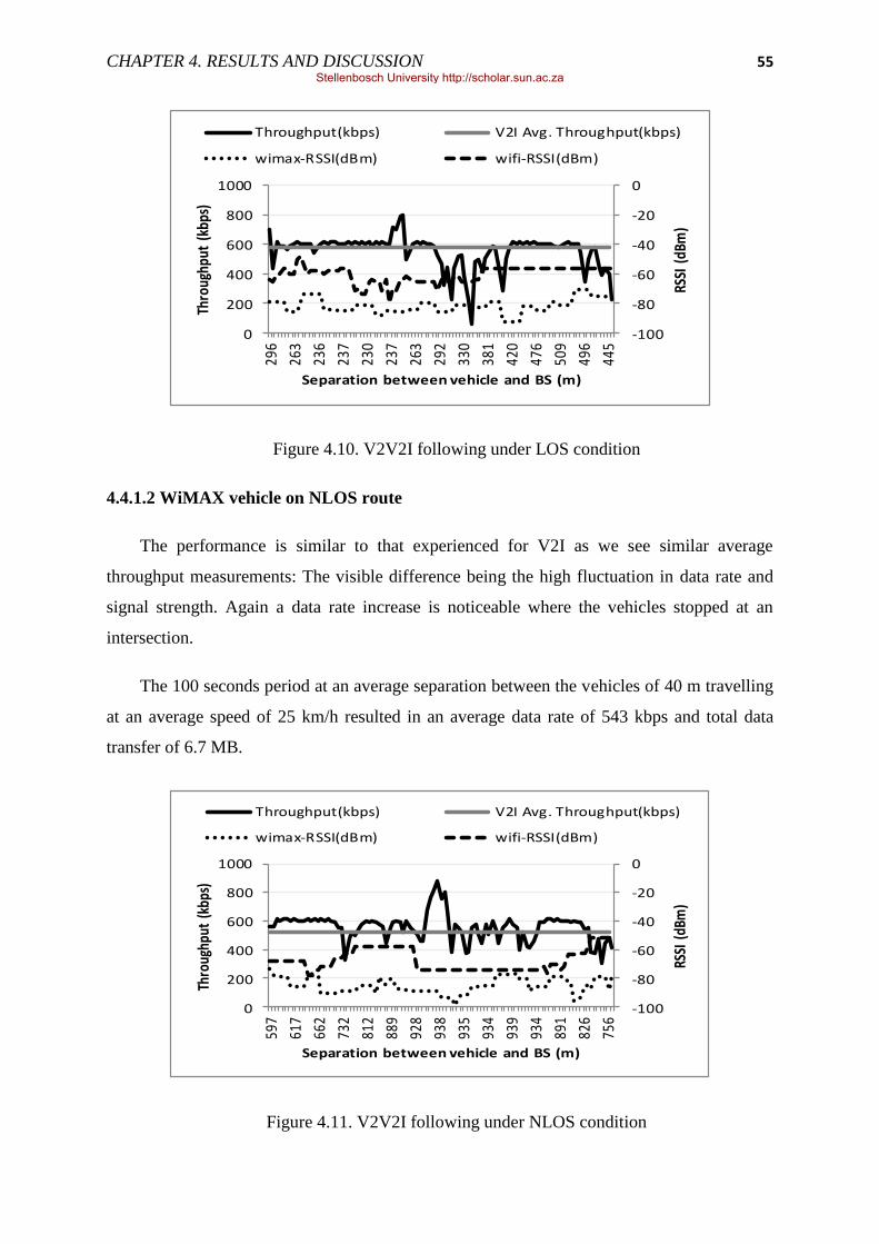
CHAPTER 4. RESULTS AND DISCUSSION 55
Figure 4.10. V2V2I following under LOS condition
4.4.1.2 WiMAX vehicle on NLOS route
The performance is similar to that experienced for V2I as we see similar average
throughput measurements: The visible difference being the high fluctuation in data rate and
signal strength. Again a data rate increase is noticeable where the vehicles stopped at an
intersection.
The 100 seconds period at an average separation between the vehicles of 40 m travelling
at an average speed of 25 km/h resulted in an average data rate of 543 kbps and total data
transfer of 6.7 MB.
Figure 4.11. V2V2I following under NLOS condition
-100
-80
-60
-40
-20
0
0
200
400
600
800
1000
296
263
236
237
230
237
263
292
330
381
420
476
509
496
445
RSSI
(dB
m)
Thro
ughp
ut (
kbps
)
Separation between vehicle and BS (m)
Throughput(kbps) V2I Avg. Throughput(kbps)
wimax-RSSI(dBm) wifi-RSSI(dBm)
-100
-80
-60
-40
-20
0
0
200
400
600
800
1000
597
617
662
732
812
889
928
938
935
934
939
934
891
826
756
RSSI
(dB
m)
Thro
ughp
ut (
kbps
)
Separation between vehicle and BS (m)
Throughput(kbps) V2I Avg. Throughput(kbps)
wimax-RSSI(dBm) wifi-RSSI(dBm)
Stellenbosch University http://scholar.sun.ac.za

CHAPTER 4. RESULTS AND DISCUSSION 56
4.4.2 Vehicles moving in opposite directions
Throughput and signal strength for vehicles moving in opposite direction under LOS and
NLOS conditions are shown in Figure 4.12 and Figure 4.13 respectively. The average
throughput for LOS and NLOS V2I is also plotted for reference. The distance between the
two vehicles is plotted on the x-axis whereby the vehicles cross each other at the centre of the
graph.
The same behaviour of Wi-Fi RSSI as in V2V is seen here where it increases as vehicles
come close to each other but the data rate does not increase with RSSI as we saw before
because of the inclusion of WiMAX.
4.4.2.1 WiMAX vehicle on LOS route
In this setup an average relative vehicle speed of 58 km/h was recorded with an average
distance from the base station of 441 m. The contact time of 36 s produced an average data
rate of 454 kbps, jitter of 10.3 ms and total data transfer of 1.83 MB.
The data rate starts lower, but quickly stabilises as soon as the link is established
between the two vehicles. The data rate peaks at the same value as in V2I when only
WiMAX is used; this shows that when within Wi-Fi range, the performance depends on the
WiMAX connection.
Figure 4.12. V2V2I moving in opposite direction LOS
-100
-80
-60
-40
-20
0
0
100
200
300
400
500
600
700
25
1
24
1
22
3
19
9
16
9
13
8
10
8
75
46
21 5
24
47
77
11
6
15
4
17
8
RSS
I (d
Bm
)
Thro
ugh
pu
t (k
bp
s)
Separation between vehicles (m)
Throughput(kbps) V2I Avg. Throughput(kbps)
wimax-RSSI(dBm) wifi-RSSI(dBm)
Stellenbosch University http://scholar.sun.ac.za

CHAPTER 4. RESULTS AND DISCUSSION 57
4.4.2.2 WiMAX vehicle on NLOS route
Under NLOS the signal strength is not stable as in LOS where the communication range
is short, due to the vehicle BS separation and presence of obstacles that continually affect the
signal. The resulting throughput is accordingly unstable. But even under unstable conditions
of signal strength the throughput on average still matches that seen in the V2I test.
The experiment was carried out under the average vehicular relative speed of 55 km/h
and average maximum separation of 192 m was reached. The average contact lasted for 35s
with an average data rate of 451 kbps producing total data transfer of 1.82 MB and 13.9 ms
jitter.
Figure 4.13. V2V2I moving in opposite direction in NLOS
4.5 Result Summary
The average values measured in all experiments performed are shown in Table 7. The
results show link duration dependence on the vehicles direction and the radio range.
Communication between vehicles traveling in opposite directions is very short lived when
compared to communication period between vehicles traveling in the same direction. Also,
the longer the radio‘s range, the longer the link duration. For this reason, in V2V
communication where Wi-Fi was used, an increase in throughput is visible when vehicles
follow each other than when moving in opposite directions. But this does not mean Wi-Fi
-100
-80
-60
-40
-20
0
0
100
200
300
400
500
600
700
192
176
159
142
135
122
104 78 46 15 20 51 84 115
144
171
RSSI
(dB
m)
Thro
ughp
ut (
kbps
)
Separation between vehicles (m)
Throughput(kbps) V2I Avg. Throughput(kbps)
wimax-RSSI(dBm) wifi-RSSI(dBm)
Stellenbosch University http://scholar.sun.ac.za
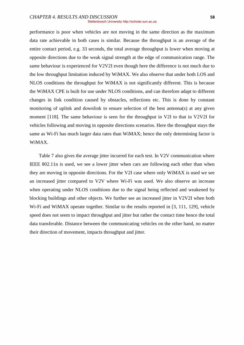
CHAPTER 4. RESULTS AND DISCUSSION 58
performance is poor when vehicles are not moving in the same direction as the maximum
data rate achievable in both cases is similar. Because the throughput is an average of the
entire contact period, e.g. 33 seconds, the total average throughput is lower when moving at
opposite directions due to the weak signal strength at the edge of communication range. The
same behaviour is experienced for V2V2I even though here the difference is not much due to
the low throughput limitation induced by WiMAX. We also observe that under both LOS and
NLOS conditions the throughput for WiMAX is not significantly different. This is because
the WiMAX CPE is built for use under NLOS conditions, and can therefore adapt to different
changes in link condition caused by obstacles, reflections etc. This is done by constant
monitoring of uplink and downlink to ensure selection of the best antenna(s) at any given
moment [118]. The same behaviour is seen for the throughput in V2I to that in V2V2I for
vehicles following and moving in opposite directions scenarios. Here the throughput stays the
same as Wi-Fi has much larger data rates than WiMAX; hence the only determining factor is
WiMAX.
Table 7 also gives the average jitter incurred for each test. In V2V communication where
IEEE 802.11n is used, we see a lower jitter when cars are following each other than when
they are moving in opposite directions. For the V2I case where only WiMAX is used we see
an increased jitter compared to V2V where Wi-Fi was used. We also observe an increase
when operating under NLOS conditions due to the signal being reflected and weakened by
blocking buildings and other objects. We further see an increased jitter in V2V2I when both
Wi-Fi and WiMAX operate together. Similar to the results reported in [3, 111, 129], vehicle
speed does not seem to impact throughput and jitter but rather the contact time hence the total
data transferable. Distance between the communicating vehicles on the other hand, no matter
their direction of movement, impacts throughput and jitter.
Stellenbosch University http://scholar.sun.ac.za
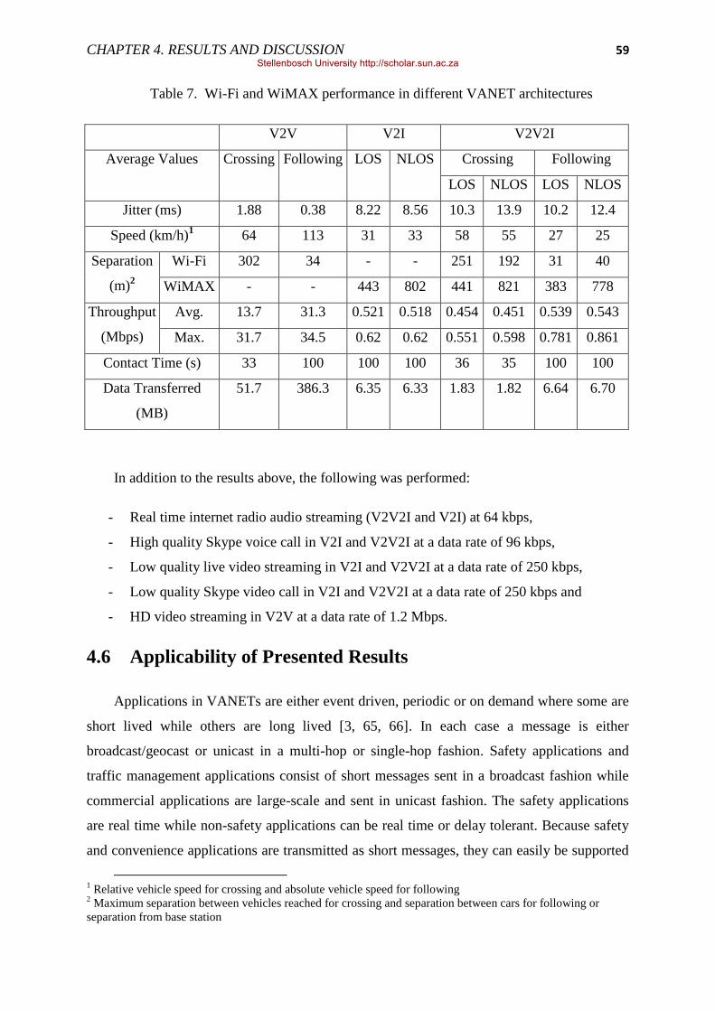
CHAPTER 4. RESULTS AND DISCUSSION 59
Table 7. Wi-Fi and WiMAX performance in different VANET architectures
V2V V2I V2V2I
Average Values Crossing Following LOS NLOS Crossing Following
LOS NLOS LOS NLOS
Jitter (ms) 1.88 0.38 8.22 8.56 10.3 13.9 10.2 12.4
Speed (km/h)1 64 113 31 33 58 55 27 25
Separation
(m)2
Wi-Fi 302 34 - - 251 192 31 40
WiMAX - - 443 802 441 821 383 778
Throughput
(Mbps)
Avg. 13.7 31.3 0.521 0.518 0.454 0.451 0.539 0.543
Max. 31.7 34.5 0.62 0.62 0.551 0.598 0.781 0.861
Contact Time (s) 33 100 100 100 36 35 100 100
Data Transferred
(MB)
51.7 386.3 6.35 6.33 1.83 1.82 6.64 6.70
In addition to the results above, the following was performed:
- Real time internet radio audio streaming (V2V2I and V2I) at 64 kbps,
- High quality Skype voice call in V2I and V2V2I at a data rate of 96 kbps,
- Low quality live video streaming in V2I and V2V2I at a data rate of 250 kbps,
- Low quality Skype video call in V2I and V2V2I at a data rate of 250 kbps and
- HD video streaming in V2V at a data rate of 1.2 Mbps.
4.6 Applicability of Presented Results
Applications in VANETs are either event driven, periodic or on demand where some are
short lived while others are long lived [3, 65, 66]. In each case a message is either
broadcast/geocast or unicast in a multi-hop or single-hop fashion. Safety applications and
traffic management applications consist of short messages sent in a broadcast fashion while
commercial applications are large-scale and sent in unicast fashion. The safety applications
are real time while non-safety applications can be real time or delay tolerant. Because safety
and convenience applications are transmitted as short messages, they can easily be supported
1 Relative vehicle speed for crossing and absolute vehicle speed for following
2 Maximum separation between vehicles reached for crossing and separation between cars for following or
separation from base station
Stellenbosch University http://scholar.sun.ac.za

CHAPTER 4. RESULTS AND DISCUSSION 60
in V2V and V2I communications whether vehicles are crossing or following each other. On
the other hand, because commercial applications are of large scale, some applications require
certain data rate threshold to be maintained, examples include live video streaming. Delay
tolerant applications have relaxed data rate requirements (can function at any available rate)
and can operate whether connections are short lived or long lived. Table 8 below shows
typical data rate requirements by some of the applications and which of the communication
strategies can support them.
Table 8. VANET applications with data rate requirement
Data Rate Application V2V V2I V2V2I
1.5 Mbps HD Video √ - -
500 kbps High quality video √ - -
128 kbps Low quality video √ √ √
100 kbps High quality voice √ √ √
24 kbps Low quality voice √ √ √
10 kbps Traffic management √ √ √
5 kbps Safety messages √ √ √
From the results gathered, vehicles following each other provide higher average
throughput and longer connection time resulting in large data transfers. Vehicles moving in
opposite directions resulted in lower average throughput and contact period based on relative
speed. Depending on the mode of communication, a certain amount of data can be transferred
hence a suitable application can be implemented. Table 9 gives the possible applications that
can be implemented for 30 seconds connection period at a relative speed of 60 km/h.
Table 9. Applications as per communication architecture
Application V2V V2I V2V2I
Safety Messaging √ - -
Torrent √ √ √
Email √ √ √
Navigation (Map Downloads) - √ √
File sharing (up to 50MB) √ - -
Stellenbosch University http://scholar.sun.ac.za

61
Chapter 5 Conclusion
Feasibility of infotainment applications in vehicular ad hoc networks depends not only
on vehicular network characteristics but as well as the communication medium in terms of its
performance under such networks. In this research, the performance of Wi-Fi as a provider of
inter-vehicular communications and WiMAX for vehicle to infrastructure communications in
a simple vehicular ad hoc network was evaluated. Experiments in scenarios with
representative vehicle speeds, levels of urbanisation, contact ranges and contact durations
were conducted.
Wi-Fi, used for the V2R and V2V connection, was found to provide reliable and high
throughput, while connected. The Wi-Fi connection was unaffected by speed and the only
distinguishable factor seems to be separation which determined whether the connection is
made. The use of external antenna proved to increase the performance in terms of
communication ranges and link duration. Ranges of up to 300 meters were achieved with
external antenna while only 150 m was reachable with normal laptop antenna.
WiMAX throughput, used for V2I communications, is severely affected by even slight
mobility. This is due to the 802.16d (2004) designed for fixed wireless communication and
not mobile communication. Once mobility is introduced error rate increases therefore forcing
the use of less aggressive modulation techniques. The WiMAX throughput is predictable and
stable for the vehicular speeds tested, but mobile throughput is a fraction of the stationary
throughput. The WiMAX throughput fluctuates for NLOS, but this does significantly not
affect the average throughput.
Applications that require high data rates, e.g. HD video transfer and large file sharing,
can easily be hosted on V2V communication because of higher Wi-Fi data rate support. The
V2I and V2V2I interface can support applications that require low data rates. The setup is
particularly well suited for delay tolerant applications. Streaming video, streaming audio and
video conferencing was successfully run in the V2V2I setup.
Stellenbosch University http://scholar.sun.ac.za

62
Chapter 6 Future Work
The results in this research present the best case scenario in vehicular networks where
only two nodes communicate where there are no collusions and contentions with other users.
It would be beneficial to know the performance where more than two nodes try to
communicate. Therefore further investigations would be performed under denser scenarios
where a number of vehicles share single medium. This will also include the employment of
multi-hop communications. Additionally the use of mobile WiMAX and the IEEE 802.11p
will be experimented to realise more realistic communications behaviours in VANETs.
The existence of different multiple wireless communication technologies in VANETs
would certainly require a way of managing them, i.e. a mechanism that decides which
wireless technology to use. This mechanism on the other hand should allow for availability of
safety applications‘ channels at all times irrespective of the technology currently selected for
use. Thus, further research would be undertaken to investigate the implications of using
multiple wireless technologies and management of their coexistence.
Knowing the performance of the individual communication technologies and their
coexistence, the next step involves enabling content or data sharing. Because communication
links are short lived in VANET‘s, content downloading and or uploading can only be done in
blocks. Thus, content data retrieval and indexing, needs a special attention; therefore an issue
that would be investigated in the coming research. Another important issue is the addressing
for Internet access in vehicular networks. Nodes in VANET‘s are highly mobile thus the
potential to continually change Internet gateway thus ISPs.
Stellenbosch University http://scholar.sun.ac.za

63
List of References
[1] S. Olariu and M. C. Weigle, ―Vehicular Networks from Theory to Practice‖,
COMPUTER and INFORMATION SCIENCE SERIES, 2009.
[2] M. Raya and J. P. Hubaux, ―The Security of Vehicular Ad Hoc Networks‖, ACM
SASAN, 2005.
[3] G. Marcelo, B. Fehmi, D. Marcelo, R. Savio, A. Rafael, H. Luis, C. Otto and E. Miguel,
―Measuring the Capacity of In-Car to In-Car Vehicular Networks‖, IEEE
Communications Magazine, Nov. 2009, pp 128-136.
[4] J. Miller, ―Vehicle-to-Vehicle-to-Infrastructure (V2V2I) Intelligent Transportation
System Architecture‖, IEEE Intelligent Vehicles Symposium, June 2008, pp 715-720.
[5] J. Tian and K. Rothermel, ―Building Large Peer-to-Peer Systems in Highly Mobile ad hoc
Networks: New Challenges‖, Technical Report 2002/05, University of Stuttgard, 2002.
[6] M.J. Booysen, S. Zeadally, G.-J. van Rooyen, ―Survey of media access control protocols
for vehicular ad hoc networks‖, IET Communication, 2011, Vol. 5, Iss. 11, pp. 1619–
1631.
[7] J. Eriksson, L. Girod, B. Hull, R. Newton, H. Balakrishnan, and S. Madden, ―The Pothole
Patrol: Using a Mobile Sensor Network for Road Surface Monitoring‖, In MobiSys‘08,
Breckenridge, Colorado, June 2008.
[8] B. Hull, V. Bychkovsky, K. Chen, M. Goraczko, A. Miu, E. Shih, Y. Zhang, H.
Balakrishnan, and S. Madden, ―CarTel: A Distributed Mobile Sensor Computing
System‖, In ACM SenSys, Boulder, CO, USA, Oct.-Nov. 2006.
[9] U. Lee, E. Magistretti, M. Gerla, P. Bellavista, P. Lio, and K.-W. Lee, ―Bio-inspired
Multi-Agent Data Harvesting in a Proactive Urban Monitoring Environmen‖, Elsevier Ad
Hoc Networks Journal, Special Issue on Bio-Inspired Computing and Communication in
Wireless Ad Hoc and Sensor Networks, 2008.
[10] U. Lee, E. Magistretti, B. Zhou, M. Gerla, P. Bellavista, and A. Corradi, ―MobEyes:
Smart Mobs for Urban Monitoring with Vehicular Sensor Networks‖, IEEE Wireless
Communications, 13(5):51–57, Sept.-Oct. 2006.
[11] U. Lee, E. Magistretti, B. Zhou, M. Gerla, P. Bellavista, and A. Corradi,
―Dissemination and Harvesting of Urban Data using Vehicular Sensor Platforms‖, IEEE
Transaction on Vehicular Technology, 2008.
[12]
Stellenbosch University http://scholar.sun.ac.za

64
[13] H. Hartenstein, H. Fübler, M. Mauve and W. Franz, ―Simulation Results and Proof-
of-Concept Implementation of the FleetNet Position-Based Router‖, Personal Wireless
Communications (PWC 2003), Venice, Italy, Sept. 2003, pp. 192–197.
[14] C. Tchepnda, H. Moustafa, H. Labiod and G. Bourdon, ―Securing Vehicular
Communications: An Architectural Solution Providing a Trust Infrastructure,
Authentication, Access Control and Secure Data Transfer‖, ACM Autonet in conjunction
with Globecom 2006.
[15] K. Lee, S.-H. Lee, R. Cheung, U. Lee, and M. Gerla, ―First experience with
Cartorrent in a Real Vehicular ad hoc Network Test-bed,‖ Mobile Networking for
Vehicular Environments, 2007, pp. 109–114.
[16] U. Varsheney, ―Vehicular Mobile Commerce‖, IEEE Computer Magazine, Dec. 2004.
[17] T. D. C. Little and A. Agarwal, ―Connecting Vehicles to ‗The Grid‘‖, in Proc. NITRD
National Workshop on High-Confidence Automotive Cyber-Physical Systems, Troy, MI,
April 2008.
[18] T. D. C. Little and A. Agarwal, ―An Information Propagation Scheme for Vehicular
Networks‖, in Proc. IEEE Intelligent Transportation Systems Conference (ITSC), Vienna,
Austria, September 2005, pp. 155–160.
[19] A. Agarwal and T. D.C. Little, ―Role of Directional Wireless Communication in
Vehicular Networks‖, In Proc. IEEE Intelligent Vehicles Symposium (IV ‘10), San
Diego, CA. June, 2010.
[20]
[21] IEEE P802.11p: Draft Amendment to standard for Information technology -
Telecommunications and information exchange between systems—LAN/MAN Specific
Requirements—Part 11: Wireless LAN Medium Access Control (MAC) and Physical
Layer (PHY) specifications: Wireless Access in Vehicular Environments (WAVE),
2007/2010.
[22] C. Wang, X. Cheng and D. Laurenson, ―Vehicle-to-Vehicle Channel Modelling and
Measurements: Recent Advances and Future Challenges‖, IEEE Communications
Magazine, Nov. 2009, pp 96-103.
[23] IEEE Standard for Information technology—Telecommunications and information
exchange between systems—Local and metropolitan area networks—Specific
requirements Part 11: Wireless LAN Medium Access Control (MAC) and Physical Layer
(PHY) Specifications, 2007.
Stellenbosch University http://scholar.sun.ac.za
65
[24] IEEE Standard for Information technology—Telecommunications and information
exchange between systems—Local and metropolitan area networks—Specific
requirements Part 11: Wireless LAN Medium Access Control (MAC) and Physical Layer
(PHY) Specifications, 2009.
[25] IEEE Standard for Local and metropolitan area networks Part 16: Air Interface for
Broadband Wireless Access Systems, 2009.
[26]
[27] S. Xuand T. Saadawi, ―Does the IEEE 802.11 MAC protocol work well in multihop
wireless ad hoc networks?‖, IEEE Commun. Mag., vol. 39, pp. 130–137, Mar. 2001.
[28] D. D. Perkins, H. D. Hughes, and C. B. Owen, ―Factors affecting the performance of
ad hoc networks‖, IEEE Int. Conf. Communications, New York, 2002.
[29] V. Naumov, R. Baumann, and T. Gross, ―An Evaluation of Inter-Vehicle Ad Hoc
Networks Based on Realistic Vehicular Traces‖, in Proc. 7th ACM Intl. Symp. on Mobile
Ad Hoc Networking and Computing (MobiHoc ‘06), Florence, Italy, May 2006, pp. 108–
119.
[30] H. Fübler, M. Mauve, H. Hartenstein, D. Vollmer, and M. Käsemann, ―MobiCom
poster: Location Based Routing for Vehicular Ad Hoc Networks‖, in Proc. Intl.
Conference on Mobile Computing and Networking (MOBICOM ‘02), vol. 7, no. 1,
Atlanta, GA, USA, Sept. 2002, pp. 47–49.
[31] L. Briesemeister, L. Schafers, and G. Hommel, ―Disseminating messages among
highly mobile hosts based on inter-vehicle communication‖, IEEE Intelligent Vehicles
Symp., Dearborn, Oct. 2000.
[32] P. Papadimitratos and Z. J. Haas, ―Secure routing for mobile ad hoc networks‖, SCS
Communication Networks and Distributed Systems Modeling and Simulation Conf., San
Antonio, Jan. 2002.
[33] Y.-C. Hu, A. Perrig, and D. B. Johnson, ―Ariadne: A secure on-demand routing
protocol for ad hoc networks‖, Working Session Security ad hoc Networks, Lausanne,
Switzerland, 2002.
[34]
[35] Car2Car Communication Consortium Manifesto v1.1, Overview of the C2C-CC
System, August 2007. http://www.car-to-car.org/ accessed 27 Jun. 11.
[36] K. C. Lee, U. Lee and M. Gerla, ―Survey of Routing Protocols in Vehicular Ad Hoc
Networks‖, Information science reference, Advances in Vehicular Ad-Hoc Networks:
Developments and Challenges, 2010.
Stellenbosch University http://scholar.sun.ac.za

66
[37] S. Sun, J. Kim, Y. Jung, and K. Kim, ―Zone-based Greedy Perimeter Stateless
Routing for VANET‖, in Proceedings of International Conference on Information
Networking (ICOIN 2009), January 2009,
[38] S. E. Chung, J. Yoo and C. K. Kim, ―A cognitive MAC for VANET based on the
WAVE systems‖, in Proceedings of 11th International Conference on Advanced
Communication Technology (ICACT 2009), February 2009, Vol. 1, pp 41 – 46.
[39] S. Ali, and S. Bilal, ―An Intelligent Routing protocol for VANETs in city
environments‖, in Proceedings of 2nd International Conference on Computer, Control and
Communication (IC4 2009), Karachi, Pakistan, February 2009.
[40] C. Harsch, A. Festag, and P. Papadimitratos, ―Secure Position-Based Routing for
VANETs‖, in Proceedings of IEEE 66th Vehicular Technology Conference (VTC-2007),
Fall. 2007, September 2007.
[41]
[42] D. Yu, and Y. B. Ko, ―FFRDV: Fastest-Ferry Routing in DTN-enabled Vehicular Ad
Hoc Networks‖, in Proceedings of 11th International Conference on Advanced
Communication Technology 2009 (ICACT 2009), February 2009, Vol. 2, pp 1410 –
1414.
[43] S. Ali, and S. Bilal, ―An Intelligent Routing protocol for VANETs in city
environments‖, in Proceedings of 2nd International Conference on Computer, Control and
Communication 2009, IC4 2009, February 2009.
[44] B. Mohandas, and R. Liscano, ―IP address configuration in VANET using centralized
DHCP‖, in Proceedings of 33rd IEEE Conference on Local Computer Networks,
Montreal, Canada, October 2008.
[45] S. Kohli, B. Kaur and S. Bindra, ―A comparative study of Routing Protocols in
VANET‖, ISCET 10, pp.173.
[46] H. Fübler, M. Mauve, H. Hartenstein, M. Käsemann and D. Vollmer, ―A Comparison
of Routing Strategies for Vehicular Ad Hoc Networks‖, technical report, TR-02-003,
Department of Computer Science, University of Mannheim, July 2002.
[47] M. Mauve, J.Widmer, and H. Hartenstein, ―A survey on position-based routing in
mobile ad hoc networks‖, IEEE Network, vol. 15, pp. 30–39, Feb. 2001.
[48] B. Karp and H. Kung, ―Greedy Perimeter Stateless Routing for Wireless Networks‖,
in Proceedings of ACM International Conference on Mobile Computing and Networking
(MobiCom 2000), Boston, MA, August 2000, pp 243-254.
Stellenbosch University http://scholar.sun.ac.za

67
[49] V. Naumov, & T. Gross, ―Connectivity-Aware Routing (CAR) in Vehicular Ad-hoc
Networks‖, in Proceedings of 26th IEEE International Conference on Computer
Communications, Infocom 2007, Anchorage, Alaska, 2007.
[50] I. Leontiadis and C. Mascolo, ―GeOpps: Geographical Opportunistic Routing for
Vehicular Networks‖, in Proceedings of IEEE International Symposium on World of
Wireless, Mobile and Multimedia Networks (WoWMoM 2007), Helsinki, Finland, 2007.
[51] B. Karp, & H. Kung, ―Greedy Perimeter Stateless Routing for Wireless Networks‖, in
Proceedings of ACM International Conference on Mobile Computing and Networking
(MobiCom 2000), Boston, MA, August 2000, pp 243-254.
[52] J. Blum, A. Eskandarian and L. Hoffman, ―Mobility management in IVC networks‖,
in IEEE Intelligent Vehicles Symposium, 2003.
[53] Y.-B. Ko and N. H. Vaidya, ―GeoTORA: A protocol for geocasting in mobile ad hoc
networks‖, International Conf. Network Protocols, Osaka, Japan, Nov. 2000.
[54] C. Maihöfer, ―A survey of geocast routing protocols‖, IEEE Communications Surveys
& Tutorials, vol. 6, no. 2, pp. 32–42, 2004.
[55] C. Maih¨ofer, T. Leinm¨uller, and E. Schoch, ―Abiding Geocast: Time-Stable Geocast
for Ad Hoc Networks‖, In ACM VANET‘05, Cologne, Germany, Sept. 2005.
[56] Y. Chen, Y. Lin, and S. Lee, ―A Mobicast Routing Protocol for Vehicular Ad Hoc
Networks, ACM/Springer Mobile Networks and Applications (MONET)‖, Vol. 15, No. 1,
February 2010, pp. 20-35.
[57] M. Torrent-Moreno, D. Jiang, and H. Hartenstein, ―Broadcast Reception Rates and
Effects of Priority Access in 802.11-based Vehicular Ad-hoc Networks‖, In ACM
VANET, Philadelphia, PA, USA, Oct. 2004.
[58] Q. Xu, T. Mak, J. Ko, and R. Sengupta, ―Vehicle-to-Vehicle Safety Messaging in
DSRC‖, In ACM VANET, Philadelphia, PA, USA, Oct. 2004.
[59] G. Korkmaz, E. Ekici, F. Ozguner, and U. Ozguner, ―Urban Multi-Hop Broadcast
Protocols for Inter-Vehicle Communication Systems‖, In ACM VANET, Philadelphia,
PA, USA, Oct. 2004.
[60] K. Tang and M. Gerla, ―MAC Reliable Broadcast in Ad Hoc Networks‖, In IEEE
MILCOM‘01, Washington, D.C., Oct. 2001.
[61] M. T. Sun, L. Huang, A. Arora, and T. H. Lai, ―Reliable MAC Layer Multicast in
IEEE Wireless Networks‖, In ICCP‘02, Vancouver, Aug. 2002.
[62]
Stellenbosch University http://scholar.sun.ac.za
68
[63] S. Biswas, R. Tatchikou and F. Dion, ―Vehicle-to-vehicle wireless communication
protocols for enhancing highway traffic safety‖, IEEE Communication Magazine, Vol.
44, No. 1, January 2006, pp 74–82.
[64]
[65] P. Panos, F. Arnaud, E. Knut, B. Roberto and C. Stefano, ―Vehicular Communication
Systems: Enabling Technologies, Applications and Future Outlook on Intelligent
Transportation‖, IEEE Communications Magazine, Nov. 2009, pp 84-95.
[66] F. Bai, H. Krishnan, V. Sadekar, G. Hollan, and T. Elbatt ―Towards Characterizing
and Classifying Communication-based Automotive Applications from a Wireless
Networking Perspective‖, In Proceedings of IEEE Workshop on Automotive Networking
and Applications (AutoNet), Dec. 2006.
[67] A. Agarwal and T. D. C. Little, ―Prospects for Networked Vehicles of the Future‖, in
Proc. Smart Transportation Workshop in IEEE Real-Time and Embedded Technology
and Applications Symposium (RTAS), Bellevue, WA, USA, April 2007.
[68]
[69] M. Caliskan, D. Graupner, and M. Mauve, ―Decentralized Discovery of Free Parking
Places‖, In ACM VANET, Los Angeles, CA, USA, Sept. 2006.
[70] M. D. Dikaiakos, S. Iqbal, T. Nadeem, and L. Iftode, ―VITP: An Information Transfer
Protocol for Vehicular Computing‖, In ACM VANET, Cologne, Germany, Sept. 2005.
[71] M. Guo, M. H. Ammar, and E. W. Zegura, ―V3: A Vehicle-to-Vehicle Live Video
Streaming Architecture‖, In PerCom‘05, Mar. 2005.
[72] U. Lee, J.-S. Park, E. Amir, and M. Gerla, ―FleaNet: A Virtual Market Place on
Vehicular Networks‖, In V2VCOM‘06, San Jose, CA, July 2006.
[73] U. Lee, J.-S. Park, J. Yeh, G. Pau, and M. Gerla, ―CodeTorrent: Content Distribution
using Network Coding in VANETs‖, In MobiShare‘06, Los Angeles, CA, Sep. 2006.
[74]
[75] A. Nandan, S. Tewari, S. Das, G. Pau, M. Gerla, and L. Kleinrock, ―AdTorrent:
Delivering Location Cognizant Advertisements to Car Networks‖, In IEEE/IFIP WONS,
Les Menuires, France, Jan. 2006.
[76] J.-S. Park, U. Lee, S. Y. Oh, M. Gerla, and D. Lun, ―Emergency Related Video
Streaming in VANETs using Network Coding‖, In ACM VANET‘06, Los Angeles, CA,
USA, Sept. 2006.
Stellenbosch University http://scholar.sun.ac.za
69
[77] Y. Zang, S. Sories, G. Gehlen, and B. Walke, ―Towards a European Solution for
Networked Cars - Integration of Car-to-Car technology into cellular systems for vehicular
communication in Europe‖, ITU, Geneva, Switzerland, Mar 2009.
[78] P. Jacquet, B. Mans, and G. Rodolakis. ―Information propagation speed in Delay
Tolerant Networks: Analytic upper bounds‖, In Proc. of IEEE ISIT 2008, Toronto,
Ontario (Canada), July 2008.
[79] http://www.etsi.org/
[80] http://www.ieee.org/
[81] B. O‘Hara and A. Petrick, ―IEEE 802.11 Handbook,‖ 2nd ed. IEEE Press, New York,
2005.
[82] A. Molisch, ―Wireless Communications,‖ Wiley, West Sussex, 2005.
[83] A. Goldsmith, ―Wireless Communications,‖ Cambridge, New York, 2005.
[84] ―Wireless Access in Vehicular Environments (WAVE) Networking Services, IEEE
1609.3/D15‖, 2006.
[85] W. Fisher and B. Cash, ―IEEE 802.11p Draft Review‖, ARINC, Inc Sept. 2004.
[86] X. Ma, X. Chen and H.H. Refai. ―Performance and Reliability of DSRC Vehicular
Safety Communication: A Formal Analysis‖, EURASIP Journal on Wireless
Communications and Networking, Special issue on Wireless Access in Vehicular
Environments, January 2009.
[87] Y. Qian and N. Moayeri, ―Design Secure and Application-oriented VANET‖, IEEE
2008.
[88] D. Jiang, V. Taliwal, A. Meier and W. Holfelder, ―Design of 5.9 GHz DSRC-based
Vehicular Safety Communication‖, IEEE Wireless Communications, October 2006, pp 36
– 43.
[89] S. F. Hasan, X. Ding, N. H. Siddique and S. Chakraborty, ―Measuring Disruption in
Vehicular Communications‖, IEEE TRANSACTIONS ON VEHICULAR
TECHNOLOGY, VOL. 60, NO. 1, JANUARY 2011, pp 148 – 159.
[90] Y. Qian and N. Moayeri, "Medium Access Control Protocols for Vehicular
Networks", in Vehicular Networks: Techniques, Standards, and Applications, H.
Moustafa and Y. Zhang, Eds. CRC Press, 2009, ch. 3, pp. 41-62.
[91] N. Ferreira, J. A. Fonseca, and J. S. Gomes, "On the adequacy of 802.11p MAC
protocols to support safety services in ITS", in Emerging Technologies and Factory
Automation, 2008. ETFA 2008. IEEE International Conference on, Hamburg, 2008, pp.
1189-1192.
Stellenbosch University http://scholar.sun.ac.za

70
[92] Y. Kudoh, ―DSRC Standards for multiple Applications‖, 11th World Congress on ITS
Nagoya, Aichi 2004.
[93] IEEE 1609.0/D0.7, Draft Standard for Wireless Access in Vehicular Environments
(WAVE) – Architecture, January 2009.
[94] IEEE 1609.4, Trial-Use Standard for Wireless Accesses in Vehicular Environments
(WAVE) – Multi-channel Operation, October 2006.
[95] IEEE Standard for Wireless LAN Medium Access Control (MAC) and Physical Layer
(PHY) Specifications, June 2007, Std. 802.11-2007.
[96] http://www.wimaxforum.org/ accessed 27 Jun. 11.
[97] J. G. Andrews, A. Ghosh and R. Muhamed, ―Fundamentals of WiMAX
Understanding Broadband Wireless Networking‖, Prentice Hall Communications
Engineering and Emerging Technologies Series, 2007.
[98] P. Mach and R. Bestak, ―WiMAX performance evaluation‖, Proceedings of the Sixth
International Conference on Networking (ICN'07), IEEE Computer Society, 2007.
[99]
[100] A. Kumar, ―Mobile Broadcasting with WiMAX: Principles, Technology, and
Applications‖, Elsevier Focal Press, 2008.
[101] Kwang-Cheng Chen, J. Roberto and B. de Marca, ―MobileWiMAX‖, IEEE PRESS,
JohnWiley & Sons Ltd, 2008.
[102] J. G. Andrews, A. Ghosh and R. Muhamed, ―Fundamentals of WiMAX
Understanding Broadband Wireless Networking‖, Prentice Hall Communications
Engineering and Emerging Technologies Series, 2007.
[103] Marcos D. Katz and Frank H.P. Fitzek, ―WiMAX Evolution: Emerging Technologies
and Applications‖, John Wiley & Sons Ltd, 2009.
[104] M. Aguado, J. Matias, E. Jacob and M. Berbineau, ―The WiMAX ASN Network in
the V2I scenario‖, IEEE, 2008.
[105] K. Etemad, ―Overview of Mobile WiMAX Technology and Evolution‖, IEEE
Communications Magazine, October 2008.
[106] A. Qureshi, J. Carlisle, and J. Guttag, ―Tavarua: Video Streaming with WWAN
Striping‖, In Proc. ACM Multimedia 2006, Santa Barbara, CA, Oct. 2006, pp 327-336.
[107] CarTalk 2000 Project. http://www.cartalk2000.net accessed 27 Jun. 11.
[108] CARLINK. CARLINK D2.1 - Architecture definition. Chapter 1: Physical platform
overview. CARLINK consortium, September 2007. http://carlink.lcc.uma.es/ accessed 27
Jun. 11.
Stellenbosch University http://scholar.sun.ac.za

71
[109] A. Festag, G. Noecker, M. Strassberger, A. Lübke, B. Bochow, M. Torrent-Moreno,
S. Schnaufer, R. Eigner, C. Catrinescu, and J. Kunisch, ―NoW – Network on Wheels‘:
Project Objectives, Technology and Achievements‖, Proceedings of 5rd International
Workshop on Intelligent Transportation (WIT), Hamburg, Germany, March 2008, pp.
211-216: http://www.network-on-wheels.de/documents.html accessed 27 Jun. 11.
[110] A. Tufail, M. Fraser, A. Hammad, K. Ki Hyung and S. Wha Yoo, ―An Empirical
Study to Analyze the Feasibility of WIFI for VANETs‖, IEEE Communications
Magazine, April 2008, pp 553-558.
[111] M. Wellens, B. Westphal, and P. Mahonen, ―Performance Evaluation of IEEE
8002.11-based WLANs in Vehicular Scenarios‖, in IEEE VTC 2007, April 2007, pp
1167-1171.
[112] C. Chou, C. Li, W. Chien, and K. Lan, ―A Feasibility Study on Vehicle-to-
Infrastructure Communication: Wi-Fi vs. WiMAX‖, In Proc. of the Tenth International
Conference on Mobile Data Management: Systems, Services and Middleware, 2009.
MDM‘09, May 2009, pp 397–398.
[113] I. Msadaa, P. Cataldi, and F. Filali, ―A Comparative Study between 802.11p and
Mobile WiMAX-based V2I Communication Networks‖, Fourth International Conference
on Next Generation Mobile Applications, Services and Technologies (NGMAST), July
2010, pp 186 – 191.
[114] A. Benslimane, T. Taleb, and R. Sivaraj, ―Dynamic Clustering-Based Adaptive
Mobile Gateway Management in Integrated VANET – 3G Heterogeneous Wireless
Networks‖, IEEE Journal on Selected Areas in Communications, Vol. 29. No. 3, Mar.
2011, pp 559-570.
[115] J. Eriksson, H. Balakrishnan and S. Madden, ―Cabernet: Vehicular Content Delivery
Using WiFi‖, ACM, Mobicom ‘08, September 2008.
[116] W. Viriyasitavat, F. Bai, and O.K. Tonguz, ―Dynamics of Network Connectivity in
Urban Vehicular Networks‖, IEEE Journal on Selected Areas in Communications, Vol.
29. No. 3, Mar. 2011, pp 515-533.
[117] http://www.edimax.com/en/index.php user manual, Accessed 27 Jun. 11.
[118] BreezeMAX™ TDD Micro Base Station System Manual: http://www.alvarion.com/,
accessed 27 Jun. 11.
[119] Iperf tool: http://openmaniak.com/iperf.php, Accessed 27 Jun. 11.
[120] NetMeter tool: http://www.hootech.com/NetMeter/, Accessed 27 Jun. 11.
Stellenbosch University http://scholar.sun.ac.za

72
[121] G. Holland and N. Vaidya, ―Analysis of the TCP Performance over Mobile Ad Hoc
Networks‖, Proceedings of the ACM International Conference on Mobile Computing and
Networking (MobiCom‘99), Seattle (WA), August 1999, pp. 207-218.
[122] G. Holland, Nitin and H. Vaidya ―Analysis of TCP Performance over Mobile Ad Hoc
Networks‖, ACM/Kluwer Journal of Wireless Networks, (2002) pp. 275-288.
[123] K. Chandran, S. Raghunathan, S. Venkatesan and R. Prakash, ―A Feedback Based
Scheme for Improving TCP Performance in Ad Hoc Wireless Networks‖, IEEE Personal
Communication Magazine, Special Issue on Ad Hoc Networks, Vol. 8, No. 1, February
2001, pp. 34-39.
[124] J. Liu and S. Singh, ―ATCP: TCP for mobile ad hoc networks‖, IEEE Journal on
Selected Areas in Communications (J-SAC), July 2001.
[125] Z. Fu, X. Meng and S. Lu, ―How Bad TCP Can Perform in Mobile Ad Hoc
Networks‖, Proceedings of the IEEE Symposium on Computers and Communications
(ISCC 2002), Taormina-Giardini Naxos (Italy), July 2002, pp. 298-303.
[126] A. Ahuja, S. Agarwal, J. P. Singh and Rajeev Shorey, ―Performance of TCP over
different routing protocols in mobile ad-hoc networks,‖ Proceedings of the IEEE
Vehicular Technology Conference (VTC 2000), Tokyo, Japan, May 2000.
[127] T.D. Dyer, R.V. Boppana ―A Comparison of TCP Performance over Three Routing
Protocols for Mobile Ad Hoc Networks‖, Proceedings of the ACM Symposium on
Mobile Ad Hoc Networking & Computing (MobiHoc), October 2001.
[128] K. Tang, M. Gerla, ―Fair Sharing of MAC under TCP in Wireless Ad Hoc Networks‖,
Proceedings of IEEE MMT‘99, Venice, October 1999.
[129] V. Gonzales, A. Santos, C. Pinart, and F. Milagro, ―Experimental Demonstration of
the Viability of IEEE 802.11b based Inter-Vehicle Communications‖, in TridentCom
2008, Mar. 2008.
Stellenbosch University http://scholar.sun.ac.za