
Martin Bojowald- Spherically Symmetric Quantum Geometry: States and Basic Operators

R 74 ~hilips Res. Rep. 3, 102-120, 1948
ON THE THEORY OF SPHERICALLY SYMMETRICINHOMOGENEOUS WAVE GUIDES, IN CONNECTIONWITH TROPOSPHERIC B.ADIO PROPAGATION AND
UNDER-WATER ACOUSTIC PROPAGATION
by H. BREMMER 538.566.5:534.221.1:621.392
SummaryThe conception of the atmosphere as a curved wave guide consistingof an inhomogeneous medium through which radio waves and acousticwaves can he propagated, is worked out. The guiding effect iscompared with that occurring in the propagation of acoustic waves.through oceans. The properties of these two types of spherical waveguide are in many respects interrelated, but there are some essentialdifferences which are brought to the fore. These differences are dueto the fact that the product rp: (r = distance to the centre of the earth,p,(r) = index of refraction) shows at least one minimum in the caseof atmospheric propagation aud one maximum in the case of oceauicpropagation. As a consequence there is a difference, for instance, inthe distribution of the times of arrival of consecutive rays originatingfrom a point source: in the fust case the intervals between these timesare smallest- for the rays coming latest, in the second case they aresmallest for the rays arriving earliest.Some general remarks are made with respect to arbitrary sphericallysymmetric wave guides. For example, the concept of cut-off fre-quency is discussed from the point of view of the modes as well asfrom that of geometric optics.
RésuméOn considère ici l'atmosphère comme un guide d'ondes courbé,formë par une couche non-homogène, dans laquelle se prop agent desondes électromagnétiques et acoustiques. D'une manière analogueon traite Ie problème de la propagation des ondes acoustiques dansun océan. Ces deux types de guides d'ondes montrent, d'autre part,des diffërences essentielles dues à l'existence d'un minimum de rp,(r)dans Ie premier cas, et d'un maximum de la même fonction dans Ie
. second cas (r = distance au centre de la terre, p,(r) = indice derëfraction), Par exemple, la répartition des temps d'arrivé des rayonssuccessifs provenant d'une source ponctuelle: dans le premier cas lenombre de rayons arrivant par unité de temps devient de plus en plusgrand, dans Ie second cas ce nombre devient de plus en plus petit.Le problëme résumé mène à quelques remarques gënërales concer-nant les guides d'ondes à symétrie sphérique ..Par exemple, on étudiela longueur d'onde de coupure du point de vue des fonctions propresque de celui de l'optique géometrique.
l. IntroduetionThe theory of ordinary wave guides consisting of a homogeneous mediumenclosed by sharply defined walls has been investigated in detail. Next,the guided transmission of radio waves through the atmosphere, enablingthese waves to overcome the curvature of the earth's surface, led to theconcept of a wave guide consisting of an inhomogeneous infinite medium.

SPHERICALLY SYMMETRIC INHOMOGENEOUS WAV'E GUIDES
This wave guide has a sharply defined boundary at Olie side only, namelyat the earth's surface. In connection with the guiding effect, particularlythe ionized layers of the atmosphere (ionosphere) and the inhomogeneousregion immediately above the earth (troposphere) are active, though onlythe latter is predominant for micro-waves (tropospheric super-refraction).For sound waves the role of the ionosphere is taken over by the high-temperature region near the upper boundary of the stratosphere.
In all these cases we ha~e to do with spherically curved inhomogeneouswave guides possessing only a single sharply defined boundary. They maytherefore be contrasted, e.g., with the propagation of sound waves overgreat distances through the ocean, indicated by the abbreviation 'Sofar'(sound fixing and ranging). Here we have an inhomogeneous spherical waveguide where propagation takes place between two .sharply defined bound-aries (the surface and the bottom of the ocean). In what follows we shallinvestigate in detail the general character of such spherical inhomogeneouswave guides; they are wholly determined by their refractive index p, as afunction of the distance r to the centre of the earth if we neglect localinhomogeneities in the horizontal direction. In partionlar we shall considerthe cases of tropospheric super-refraction and Sofar; these constituteillustrative examples of properties that are opposite in many respects.Moreover, these two examples are relatively simple since (a) the influenceof dispersion is negligible, (b) the function p, may be approximated by aparabolic one throughout the whole space (the same is not applicable whenconsidering the guiding effect of the ionosphere, whose layers are separatedfrom the earth by a nearly homogeneous space).
2. General geometric-optical considerations
In a geometric-optical *) treatment the course of the rays within aspherically symmetric inhomogeneous medium is determined by Snellius'slaw, which may be written in the form:
rp, sin 7: = constant = C,
7: being the angle between the tangent of the ray and the vertical.The effect of the curvature is clear from the occurrence of the product
rp, rather than p,. Special attention should be paid to the sign ofthe slope ofrp,. As a matter of fact, a ray horizontally directed (dr/df) = 0) at somepoint P, will have its lowest point at P if P lies in a region for whichd(rp,)/dr> 0, and a highest point at P if d(rp,)/dr < O.As regards the function rp, a fundamental difference exists between
trophospheric radio propagation (referred to further on by T) and sound
*) We shall use this term for acoustic problems also. '
103
(1)

104 H.BREMMER
propagation through the ocean (abbreviated by O). In the first case, owingto exceptional meteorologie condictions, the refractive index p, of the airdecreases so rapidly with height that also the product Tp, does decreasenotwithstanding the increasing factor T. At greater heights, however, theinfluence of p" being very near to 1, becomes so small that ru increasesalmost proportionally to T. As a consequence á transition level T = TOexists, where Tp, has à minimum; under normal weather conditionsthe increase of this quantity starts right at the earth's surface (T = a).In the ease 0, however, the acoustical index of refraction p, of the sea-water first increases with increasing depth below the surface, owing to adecrease of the temperature of the water; finally, when a nearly constanttemperature of 4 oe has been attained, a decrease of p, is caused by the stillincreasing pressure. Therefore p, will now pass through a maximum value;the same then holds, at some level T = TO' for Tp" since the influence of thefactor T is relatively small in this case.
!!E..>oar
rJ./L<odr
T a52052
.Fig, 1. Survey of the signs of the slopes of p.' and TP.. for Tand O.
The immediate consequences of the minimum for Tp, in T and of themaximum in °are illustrated by fig. 1. In the first case d(Tp,}JdT is positiveabove T = Toand negative below it, so that rays horizontal at some pointwill, in the vicinity of that point, always be deflected in a direction awayfrom the To·level;in the second case the opposite holds, so that rays beinghorizontal somewhere are deflected touiards the To·level in neighbouringpoints and will cross the To·levelat a distant point. Moreover there exists,for both Tand 0, a level T = Ti at which dp,JdT = 0 and where each raycrossing that level will have an inflection point; this level is situated abover = TO for T and below it for 0. A point of conformity between Tand, °is the fact that a ray starting horizontally at some point of the transitionlevel T = TO will never deviate from that level and consequently willfollow-the curvature of the earth.Another consequence of the described difference in behaviour of Tp, is that
the guiding effect can he maintained. by the inhomogeneous medium itselfin the case 0, whereas in the case T the presence of a sharply defined inner

SPHERICALLY SYMMETRIC INHOMpGENEOUS WAVE GUIDES 105
boundary is essential. In fact, in 0 the rays starting with an elevation (withrespect to the horizon) that is not too great, ....vill he compelled by the in-homogeneity ofthe medium to oscillate around-the To-level.In T, however,the rays can be prevented from being deflected"too far away from the TO-
level only by the presence of a sharply defined reflecting surface or, occa-sionally, by the existence of a maximum of ru beside the minimum. Thus, 'in T, the earth's surface is mostly essential for rays to be guided within the'space a< T < TO' In 0, on the contrary, the boundaries formed by the sur-face and the bottorn of the sea constitute adverse conditions for the propa-gation since they cause reflection losses for those rays that cannot be.gradually reflected within the inhomogeneous medium itself, the initialelevation being too great (compare section 8).
T a
3. The beam of rays originating in a point source
For the sake of simplicity we assume a source Q at the earth's surfacein the case T, and one at the To-levelin the case 0 (the latter situation isapproximately realized in Sofar-practice). The energy radiated by thesource is transmitted along the geometric-optical rays radiating from Q,while each ray can be marked by its elevation angle t:« or 7:0 respectively(see fig. 2). In both cases Tand 0 there are important limiting values forthese angles. First, in T, we have to do with the angle 7:1' which is deter-mined by
• TO fl(TO)Sill 7:1= ()'a fl a
the corresponding ray approaching the To-level asymptotically. The latterray separates the rays t:« > 7:1' which are gradually reflected downwardswithin the space a < T < TO (the 'duct'), from the rays t:« < 7:1 whichescape into space (T> TO)' Similarly, in 0 there exists a limiting ray,determined by
. a fl(a)SIn 7:1= ,
ro fl(TO)
Fig. 2. The courses of the rays radiating from a point sourse, for Tand O. ,

106 H.BREMMER
just touching the surface of the sea at some point T at a finite distance.Here this limiting ray separates the rays with 0'0 > 'Oz,which are graduallyreflected downwards, from the group of rays with 0'0 < 'Olwhich arereflected abruptly at the -surface of the sea at r . a. Moreover, a secondlimiting angle 'Ol' (> n/2) characterizes the ray that, while sent down-wards from Q, just touches the bottom of the sea.
Wenow, consider a receiver P at the same level as the source, thus atr = a or r = rorespectively. This receiver can be reached by a large numberof rays each of which may be labelled by the number of times (j) it hasgone up and down before arriving. The definition of j requires integralvalues of this parameter for T (see the examples of j = 1 and 3, fig. 2T),whereas it may be also half an integer for 0 (see j = 1 and t, fig. 20).
Of course, the total number of hops j by-which a ray with a special value.of 'Oa'or 0'0 may reach P, depends on the distance D('Oa) or D('Oo) coveredin one single hop. In order to get an idea of the latter distances we assumethe most simple dependence of r# on r that produces a maximum for Tand a minimum for 0 at the level r = ro' The dependence in question isobtained by a quadratic formula for r2#2; accordingly we take:
(2, T)
(2,0)
The limiting angles 'Ol are then determined by
, hocot 0'1=-'
rl(3, T)
hocos 'Ol=-,
rl(3,0)
respectively. Further, the distance Iro-ril between 'the ro-Ievel and thelevel of the inflection points will in both cases be r~/ro; owing to the slightcurvature of the earth's surface, in practice this distance is very small (ofthe order of a few metres).
With the aid of formula (1), applied to the p,-functions (2), we are ableto compute the whole course of the ,rays determined by 'Oa or 0'0' and parti-cularly their single-hop ranges D('Oa) and D('Oo)' The following formulaeare valid when assuming for 0 that the ro-Ievel is situated half-waybetween the surface and the bottom of the sea (0'1'= n-'OI):

SPHERICALLY SYMMETRIC INHOMOGENEOUS WAVE GUIDES
(sinlTQ )'/1ro-rt -.--1
_ 2 • faW"'1 drD(7:a) - 2a p,(a) sin 7:a ~ 2 2() 2 2( ) . 2 1'1 1::::1. r IT p, r -a p, a sin 7:al 1
a • In (COS 7:1+ COS 7:a)1::::1 rl sin 7:a ,
COS 7:1- COS 7:a
a
(
COS 7:1)1::::1 4rI sin 7:0 arcsin --- (7:0 < 7:1) •
COS 7:0(4,0)
The integrals here given are also valid for other functions p, if the limitsof integration (apart from a and r0) are replaced by the r-values of thelevels at which the radical vanishes for the p,-function considered; theselatter levels indicate the heights of gradual reflections. The first formulaof (4,0) corresponds to rays reflected gradually within the sea, the secondo~e to rays reflected abruptly at the surface or the bottorn of the sea.Here, once more, an essential difference between T- and O-propagation
presents itself. In T-propagation D(7:a) may assume any value, whichsignifies that the receiver P may be reached always by a single-hop trans-mission (j= 1). In O-propagation, on the other hand, D(7:o) has a maximumvalue of Do = 2nr1, so that a receiver at great distances can only be reached,apart from the ray following the level r = ro, by rays going up and downa number of times at least equal to DjDo' Further numerical consequencesof this effect are dealt with in section 8.
4. The focussing of the rays
Characteristic for wave guides is their property of keeping togetherrays that, in the case of an empty space, would diverge to all directions.A measure for this effect is given by the divergence coefficient a which canb~ defined as follows. A narrow pencil of rays starting from a point sourceQ will have at some point P a cross-section dO which may be comparedwith the cross-section dO' existing in the case of propagation over thesame distance along straight lines through a homogeneous space. BY,taking
I / (5)
107
(4, T)
108 H. BREIDIER
we introduce a parameter that is smaller than 1 if the inhomogeneity has itdiverging effect and greater than 1 if its influence is a converging one.We next explain the physical importance of a. In an inhomogeneous
isotropic medium the flow of energy is propagated everywhere in the samedirection as the rays, while its magnitude is proportional to the square,A2, of the amplitude of the field. Therefore, the energy radiated at Qwithin a narrow pencil does not escape from this pencil, and it will cause aflow of energy proportional to A2 dO. Since this flow of energy has to beconstant throughout the whole pencil, the field will change proportionallyto l/VdO. In a homogéneous space, the field decreases proportionally to1fJ'dO'; in this case, 0' being proportional to D2, we obtain the well-knownlaw of inverse distance. Thereupon a = "dO'/dO represents the ratioof the actual field to the field corresponding to the same distance in thecase of propagation through a homogeneous space.When computing (5) for our radially symmetric media, we obtain the
following value for a at some point P situated on the same r-Ievel as thesource Q and having an angular distance f} from it:
~1i:"Id" I'D " df}a=-! .T sin f}
(6)
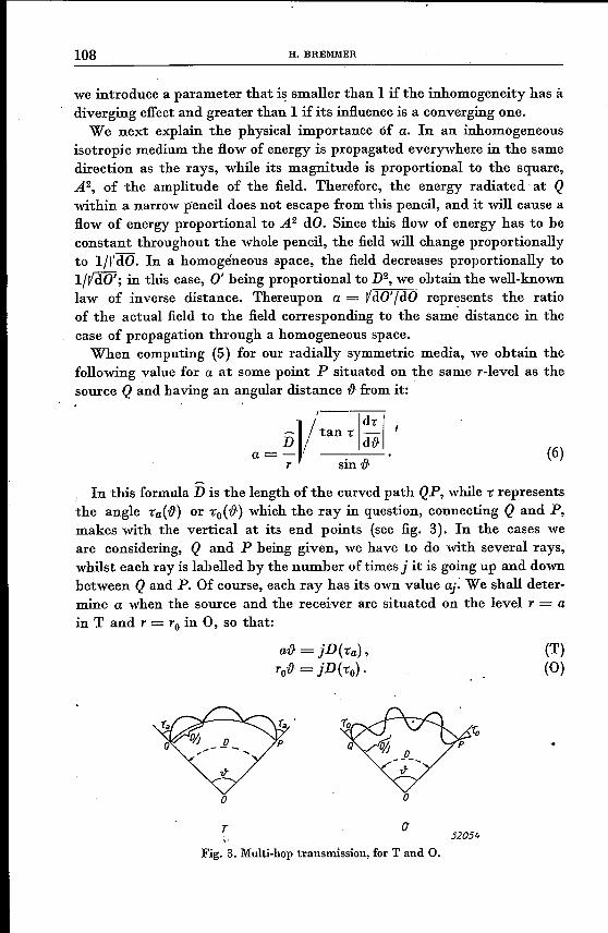
In this formula D is the length of the curved path QP, while" representsthe angle l'a(f}) or l'o(f}) which the ray in question, connecting Q and P,makes with the vertical at its end points (see fig. 3). In the cases weare considering, Q and P being given, we have to do with several rays,whilst each ray is labelled by the number of times j it is going up and downbetween Q and P. Of course, each ray has its own value aj: We shall deter-mine a when the source and the receiver are situated on the level T = ain Tand T = TO in 0, so that:
af} = jD(l'a),Tof} = jD(l'o)·
(T)(0)
o
T 0'52054
Fig. 3. Multi-hop transmission, for Tand O.

SPHERICALLY SYMMETRIC INHOJllOGENEOUS WAVE GUIDES
. On the basis of the special assumption (2) we find by using theapproximation formulae of (4) for the determination of d./df} and forthe elimination of .:
D 1aj R::! ,
·I/rla sin (DIa) -Vj sinh (Dfjrl)
S 2n DIDo î':
)
ao R::! ? sin (2n DIDo) S '
D'I. . (D )a· c-oJ • j >Do ; .0> .,"]'"" Yrosin (Dlro) ipD~-D2
In both derivations we have approximated D by D; moreover, in (7, T)cos .l~1 is assumed . In (7,0) ao corresponds to the ray j = 0 thatfollows the circle r = rO.
The expression (7, T) refers to trophospheric propagation of radiowaves for a transmitter and a receiver at the earth's surface. Here we notethe increase of aj with j, whilst the following limiting value is found forj-:roo :
a R::!l/ D =1/ f}.CX) a sin (DIa) sin f}
This quantity is slightly greater than 1. Thus not only does the ductprevent the rays from escaping away from the earth, but it even makesthem slightly more convergent than rays propagated rectilinearly. Thisconvergence effect is still more pronounced for elevated transmitters andreceivers.
As regards 0, we should bear in mind that, apart from the exceptionalvalue j= 0, j has to be greater than DIDo. Apparently aj is now decreasingwith increasing j, while it may become very great for the lowest possiblevalues of j (which are the smallest half integers above DIDo). The lattervalues correspond to rays running very near to the ro-Ievel (this well-marked focussing of rays departing with small elevation angles from r = rois not observed in T, since there the rays in question can be deflected back-wards to the ro-Ievel only by reflection against the earth's surface, andnot by the inhomogeneity of the medium near to r = ro). The focussingis particularly clear from the fact that ao becomes infinite at the pointsD = (kI2)Do (k integer). These latter points are foci in the true sense ofthe word; they constitute cusps of the caustic corresponding to the raysradiating from Q.
5. Geometric-optical derivation ofthe wave-guide condition
The divergence coefficient just described is insufficient for an explanation
109
(7, T)
(7,0)

110 H.BREMMER
of the wave-guide properties of the inhomogeneous media here consideredsince it does not account for the possibility of interference of differentrays. For a clear comprehension it is necessary to know the phases(/J(D, j) of the various j-rays upon their arrival at the receiving point P.These phases consist of a contribution determined by the changes along thecurved path of the ray and a contribution due to the intermediate re-flections (which are either gradual or abrupt). We shall discuss thesecontrihutions separately. . .
The first contribution can be represented, in the case of a mono-chromatic wave of wavelength À (measured at a level for which f1, = 1),by (2nIÀ) D(D,j). DIe equals the time needed for covering the path QP(e = velocity of propagation for f1,= 1). Owing to our ignoring dispersion,D does not depend on À. With the aid of (1) we find in the case of T, againassuming both the source and the receiver at the earth's surface,
a
Here f(DJj) is the variation in phase during one single hop, which variationis wholly determined by the corresponding horizontal distance DIj or by theelevation angle -ra leading to this one-hop distance (see fig. 3 with j = 3).The last form of (8) suggests an extension of the definition of 15 for non-integral values of j, given D; the ray j = llJ8, e.g., will cover in one hop ahorizontal distance (8/11)D and therefore has the same elevation angle -raas the ray covering the distance 8D in 11 hops. We can now derive the dif-ferential quotient of (8) with respect to j, D being constant; it then shouldbe remarked that 15 does depend also implicitly on j by means of -ra. Bydoing the same in the case of 0 (source and receiver being at the levelT = TO) we find in both cases the important, simple formula:
oD = L(D) = D-f-t(a) sin -raD,oj j
(9)
in which:
(10, T)
a
SPHERICALLY SYMMETRIC INHOMOGENEOUS WAVE GUIDES
'0+'1 COSTo
i= 2.r d; ~r2,u2(r) - r~,u~ sin2-ro("·. (iO > il) (10, 0)
These formulae are also.valid for functions ,u(r) other than (2) ifthelimitsof integration (except a) are replaced by the r-values for which the radicalvanishes (i.e. the levels of gradual reflections).
We now consider the variations in phase due to reflections. In T, wehave to do in the first place with the reflections at the earth's surface.Since, in practice, il is very near to 'Jtj2, the incidence of the rays to beconsidered is almost grazing, so that the reflection coefficient can beapproximated by -1 and the change in phase at each reflection hy 'n:Moreover, a second change in phase of -'Jtj2 is related to the passing ofeach of the highest points H of the ray; such a change in phase is charac-teristic for gradual reflections in inhomogeneous media, as may be derivedtheoretically from the W.K.B. approximation of the solution of the wàveequation that corresponds to the ray in question. Thus we find in T, thenumber of intermediate gradual reflections and of intermediate reflectionsagainst the earth's surface being j and j-I respectively, as resultingpression for the phase of the jth ray at P:
cp(D,j) = 2; D(D,j)-j i+ (j~I) 'Jt. (H, T)
In the case 0, however, when restricting ourselves to the rays withiO > il' we have to do only with intermediate gradual reflections, whichare 2j in number now. 'fo each of these reflections there will correspond,once more, a change in phase of -'Jtj2, so that instead of (H, T) we obtain:
2'Jt_ n:cp(D,j) = - D(D,j) -2j-.
A . 2 (H, 0)
From these considerations it will be clear that, if A is so great that theincrease of the first term of (H) for an increase of j by 1 is small comparedwith 2n, the rays with consecutive values of j will cancel each other to agreat extent by interference. This is only true insofar as the amplitudes oftwo consecutive rays are of the same order of magnitude; in general thishappens to be true since the divergence coefficient aj does change onlyslowly with j. Th~refore a necessary condition for favourable propagationis that there shall exist at least one group of consecutive rays arriving withphase differences of the order of 2'Jt. We thus arrive at the wave-guidecondition
max ~cp(D,j + 1) - cp(D,j)~ > 2'Jt,
III
112 Il.BRE!I1!11ER
in which the maximum is meant with respect to j, D being given. In prac-tice we can replace this unequality by the more convenient one
acpmax aj > 2n , (12)
which will bé worked out in the next section.
6. The cut-off wavelength Ao
The differential quotient acp/aj of (12) depends on D and j; nevertheless,the resulting wave-guide condition proves to be independent of D, as willnow be demonstrated. To this end we transform (12), with the aid of (11)and (9), into:
A< Ao= itmax L,
A<Ao=tmaxL.
(13, T)
(13, 0)
Here the maximum still refers to j, which parameter occurs implicitlyin L, -Ca or -Co being a function of j for given D. Now, the maximum valueof L corresponds to the minimum value of -Ca or -Co yielding a real L. Thismay be verified from the relations
dL dL. = -p,(a) D(-Ca) , d' = -p'o D(-co), (14)
d SIn -Ca SIn -Co
which, again, are valid for every p,-function. In T this minimum value of-Ca equals -Cl since the rays -Ca < -Cl escape into the space T > TO above theduct. In 0 we can similarly take as minimum value of -Co the angle -Cl;
it is true that also -co < -Cl leads to real values of L, but the correspondingrays are to be excluded since their amplitudes do not change slowlywithj, a condition necessary for the derivation of (12). In fact, the ampli-tudes of the rays with -co < -Cl diminish rapidly as a consequence of thelarge attenuation caused by the reflections of these rays against the sur-face and the bottom of the sea, these reflections not being 'total' .as arethe gradual reflections occurring for -co > -Cl' Thus, deriving the maximumvalue of L by substituting -Cl for t:« in T ànd -Cl for -co in 0, we obtain from(13):
r.
Ao= t.r d; ~T2p,2(T)-a2p,2(a)' Sin2-Clf", (15, T)
a
r.+h.
Ao= it.r d; ~T2p,2(T)-T~p,ä Sin2-Clf'"
TO-lao
(15, 0)
SPHERICALLY SYIIIJlIETRIC INHOIlIOGENEOUS WAVE GUIDES
Not only are these expressions independent ·of our assumptions regardingthe ,u-function but they are equally independent of the distance, and theythus determine an upper wavelength limit (cut-off wavelength) under verygeneral conditions. By using the formula (2) for ,u we find, by replacingonce more the factor r in the integrand of (15) by a constant value,
(16, T)
(16, 0)
These strikingly simple formulae, though dependent on the assumptionof a parabolic function for r2ft2, give in any case a qualitative idea of theconditions met in practice. In T, the small value of cos -Cl causes a verysmall value of Ao so that guided tropospheric propagation is observableonly for micro-waves; thus, for instance, from the values ho = 15 m andcos -Cl = 0'004 (whose orders of magnitude are in agreement with observ-ations at Antiqua 1), we derive }.o = 8 cm. We now make a comparisonwith the guiding effect of. the ionosphere. Here, downward gradual re-flections are possible for nearly all values of -c (though the situation is verycomplicated owing to dispersion effects); therefore we can substitute forthe limiting angle in (15, T) -Cl = 0 while, approximately, ,u is .equal to 1in nearly the whole interval of integration which extends mainly overthe homogeneous space below the ionosphere. We thus find Ao ,~ -It ho(ho = height of the ionosphere above the earth), from which the guidingproperty of the space between the earth and the ionosphere is evident forthe whole radio spectrum used in practice.
In the case of oceanic acoustic propagation, the quantities ho = 1 kmand -Cl = 78° are of the right orders of magnitude; the corresponding valueof the cut-off frequency, i.e, Jo = ciAo, leads to Jo = 3'4 hertz, by which theguiding effect is explained for all ordinary acoustic frequencies.
7. The phase-integral equation
In general the properties of wave guides are not derived by the geo-metric-optical method developed above. Particularly this method is oftenunsuitable for the computation of the field of a point source. The geo-metric-optical determination of such a field amounts to a summation ofthe contributions of the individual j-rays, a summation leading in manycases to a very slowly convergent series. Therefore these fields are usuallyderived from a linear combination ofthe characteristic solutions or 'modes'corresponding to the problem in question. Incidentally it can be demon-strated that the geometric-optical series is transformable into the seriesof modes by the so-called transformation formula of Poisson.
ll~
114 H, DRE~IMER
In many cases the modes occur as the residues of a contour integralrepresenting rigorously the field, so that their amplitudes are known atthe same time. However, the form of the modes is independent of anyspecial conditions like those referring to the presence of a point source,and, therefore, can be derived straight-forwardly. Thus in our cas,e 0,£radial symmetry of fl, the modes not dependent on the azimuth angle cpcorrespond to those solutions of the wave equation that consist .of aproduct of a function of r and a function of {j. The latter function amountsto a spherical harmonic Pv (cos {J.) so that each individual mode can be 'characterized by its special value 'jJsfor the order v,The r-function of the modes in question can he found with the aid of the
well-known W.K.B. approximation method, where the requirement ofone-valuedness and finiteness everywhere in space leads to the followingequation, the wave number kl = 2n/ A. being given,
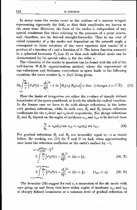
2kl{r'dr ~r2fl,2(r) _ 'jJ!("-i In ~s,('jJs) R2('jJs)~ = 2ns. (s integer, i = 1/-1). (17)" r kl ?
Here the limits of integration are either the r-values of sharply definedboundaries of the space considered, or levels for which the radical vanishes.In the former case we have to do with abrupt reflections, in the latterwith gradual reflections, while, in each case, RI and R2 denote reflectioncoefficients for the rl-level and r2-level respectively. For abrupt reflectionsRI and R2 depend on the angles of incidence "5,1 and "5,2 to be derived from
'jJs " .k = rlfl,(rl) sin "5,1 = r2,u(r2) sin '05,2,1
(18)
For gradual reflections RI and R2 are invariably equal to -i as statedbefore, By working out (17) for Tand 0 we find, when approximatingonce more the reflection coefficient at the earth's surface by -1,
(19, T)a
(19, 0)
The formulae (18) suggest for real ï's a connection of the sth mode withrays going up and down that, have either angles of incidence "5,1 and, '0$,2
at sharply defined boundaries or a common level of gradual reflection at
SPHERICALLY SYMMETRIC INHOJlWGENEOUS WAVE GUIDES
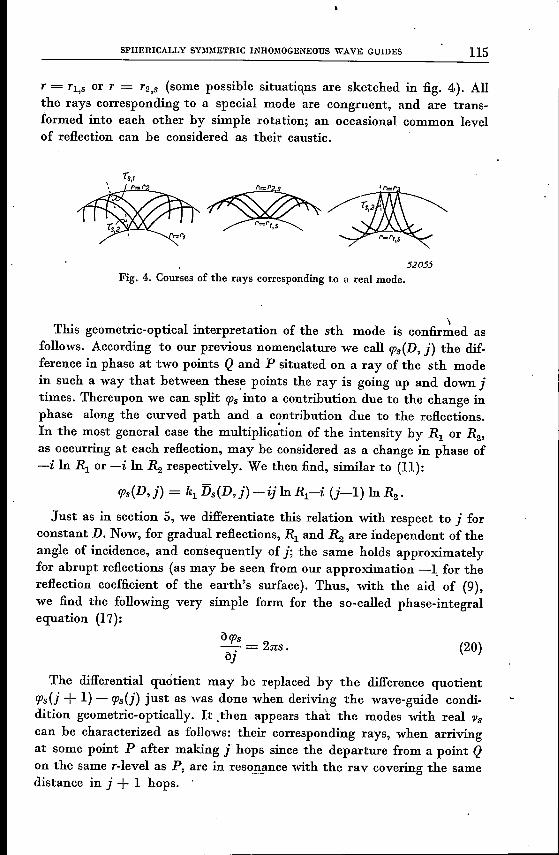
T = TI,S or T = T2,s (some possible situatiqns are sketched in fig. 4). Allthe rays corresponding to a special mode are congruent, and are trans-formed into each other by simple rotation; an occasional common levelof reflection can be considered as their caustic.
52055
Fig. 4. Courses of the rays corresponding to a real mode.
\This geometric-optical interpretation of the sth mode is confirmed as
follows. According to our previous nomenclature we call !Ps(D, j) the dif-ference in phase at two points Q and P situated on a ray of the sth modein such a way that between these points the ray is going up and down jtimes. Thereupon we can split !ps into a contribution due to the change inphase along the curved path and a c,?ntribution due to the reflections.In the most general case the multiplication of the intensity by RI or R2'as occurring at each reflection, may be considered as a change in phase of-i In RI or -i InR2 respectively. We then find, similar to (11):
!Ps(D, j) = klDs(D, j) - ij InRl-i (j-l) InR2•
Just as in section 5, we differentiate this relation with respect to j forconstant D. Now, for gradual reflections, RI and R2 are independent of theangle of incidence, and consequently of j; the same holds approximatelyfor abrupt reflections (as may be seen from our approximation -1. for thereflection coefficient of the earth's surface). Thus, with the aid of (9),we find the following very simple form for the so-called phase-integralequation (17):
O!ps-=231:s.oj
The differential quotient may be replaced by the difference quotient!Ps{j + 1) - !Ps{j) just as was done whenderiving the wave-guide condi-dition geometric-optically. It .then appears that the modes with real 'Ps
can he characterized as follows: their corresponding rays, when arrivingat some point P after making i hops since the departure from a point Qon the same r-level as P, are in resonance with the rav covering the samedistance in j + 1 hops. .
115
(20)
116 H.BREMMER
We are now able to construct the wave-guide condition (12) also fromthe point of view of the modes. In fact, the factor Pps (cos {})of the lattercorresponds to a change in intensity which is approximately proportionalto exp(ivs{}); consequently, a non-attenuated propagation in the f)-
direction is to be expected only if (20) is satisfied by at least one real rootVs. Moreover, for the possibility of such a root it is necessary that themaximum value of àep/àj for real rays does exceed 2n, since otherwise (20)cannot be satisfied for any integer s (apart from the trivial value s = 0).Thus we are again led to the condition (12) and to a corresponding cut-offwavelength A-o. When A- < A-o the number of real modes will be the greaterthe shorter the wavelength is.
From the foregoing it is evident that the field of a point source maybe considered as a combination of modes (characterized by the integers s)but equally well as a combination of contributions due to geometric-optical rays (characterized by the integer j). The latter conception isclearer inasmuch it is always connected with real rays, whereas the sameholds for the modes only if Vs is real. For numerical computations themethod of modes is particularly useful it the consideration of a smallnumber of modes suffices, i.e. when A-o/ A- is not very large, as in the prac-tical cases of super-refraction. In other cases, as in Sofar-practice, ;"0/ A-is very large for ordinary wavelengths, so that a great number of realmodes has to be considered; the number of important geometric-opticalrays, however, is small there (see below), so that the geometric-opticalmethod is very suitable. Thus the two methods appear as being mutuallycomplementary.
In Booker's theory of super-refraction the modes with real Vs are called'trapped modes' in contrast to the name 'leaking modes', applied when l'
is complex. This nomenclature clearly indicates that for the former theenergy cannot escape through the boundaries of the guide; for the latter,however, a leaking of energy through the boundaries is possible by meansof a (gradual or abrupt) refraction. Finally we remark that the modes of aninhomogeneous wave guide, enclosed between two homogeneous spaces,are transformed into surface waves when the thickness ofthe guide becomesinfinitely small. /
8. The consecutive arrival of the geometric-optical raysThe geometric-optical representation is particularly suitable when
considering a point source operating during an infinitely short time att = O. If the surrounding space is considered as homogeneous withpropagation velocity c the field of such a source will be proportional to
SPHERICALLY SYMMETRIC INHOMOGENEOUS WAVE GUIDES
where 0 is Dirac's impulse function. In an inhomogeneous space (assumedonce more spherically symmetric; source and receiving point at the same'r-Ievel) this function has to be multiplied by the divergence coefficient a and,occasionally, also by the reflection coefficients. Moreover the propagationtime Die then has to be replaced by the term Die which accounts for thelocal values cl~l of the propagation velocity. Accordingly the field due to a.ray making j intermediate hops will be proportional to
aj 0~t - ~D(D,j)~,
aj being the corresponding divergence coefficient. The distribution ofthe times of arrival, tj = Djle, of the different j-rays shows a remarkabledifference for Tand 0, as will next he discussed.
For a consideration of 'i as a function of j, given D, we write (9) asàtj/àj = Lic. The positive value of the differential quotient informs usthat the rays arrive in a sequence corresponding to their number of hops i-those with greatestj arriving latest. Moreover we conclude from (14) thatL decreases with increasing .a or .0' Hence the same holds for the timedifference tj+l-tj R:;j àtj/àj between the arrival of two consecutive rays.Here the geometrical differences between T- and O-propagations presentthemselves once more since, in T, increasing .a corresponds to a decreas-ing distance D(.a) covered in one hop and consequently to increasing j,whereas, in 0, increasing .0 corresponds to increasing D(.o) and todecreasing j (compare fig. 2 and the formulae (4». Thus, since àtj/àjdecreases in any case for increasing T, this decrease refers to increasing jin T but to decreasing j in 0. It means that for T-propagation the raysfinally arrive in a more and more rapid succession, whereas for O-propaga-tion they arrive at increasing intervals.
The differences in behaviour described depends only on whether theextremum of r a is a minimum or a maximum. Itmay again be illustratedin more detail by the specialization (2) for #. We then find (restrictingourselves for ° to t~e ·rays with To > T, and for T to the rays for whichcos Ta~ cos T,):
(tco-tl)tj R:;j tco - --'-2 - ,
J
tj = tmin (-I-+ j":in) .2 Jmin J
(22, T)
(j -=/=. 0) (22, 0)
In the first expression,
D ( COS4., 2)tI = #(a) - 1---D
e 24hg
117
(21)

\
I' ,H. Bnm!MER
signifies the time of arrival of the first ray (if also for this ray cos 't'a ~
cos 't'1), and tct:>= f.t(a) Die the time of abrupt termination of arrival ofthe rays. In the second expression, tmin = p,(ro) Die is the time of arrivalof the first ray, i.e. the ray} = 0 that follows the level r = ro; further thequantity imin= DIDo marks a lower limit for the possible number ofhops for the rays with i -::F o.Whereas in T the process terminates rigorously at the time tct:>' in 0
it terminates only practically at the timeA'¥"îiî+WîiÛ·;;:V
tmin(. 1)tI = - SID't', + -.--2 sm r,
at which a ray just touching the surface or the bottom of the sea mayarrive; of course this' ray actually arrives only if D is equal to a multipleof the distance t Dl = :n; r1 sin 't', covered by this ray by going once upand down between the ro-level and the surface, or between- the ro-Ieveland the 'bottom of the sea (the latter two were assumed at equal distancesfrom the ro-Ievel). Theoretically the process still goes on for t:» t" but therays then arriving are highly attenuated by their numerous reflectionsagainst the surface and the bottom of the sea.We shall now estimate the decay in intensity of the rays arriving after
t= t, in Sofar-practice. For those few rays which are of numerical import-ance the incidence at the sea surface is almost grazing (angle of incidence't'a ~ n12) so that the reflection coefficient may be approximated by
2R('t'a) ~ -1+ (m2-1)'/. cos 't'a,~ (23)
m = 4'35 being the refraction index for the transition from water to air.The angle of incidence itself follows from
sin 't' 1 ~ cosêr )'/. n2 0')2sin 't'a = -~ ~ -- 1- ' ç ~ 1-- cot2't', --1 .sin 't', sin 't'1 sin2 (nj,J2j) ~ 8 "
Hence we derive from (23):
R('t'a) ~ -1+__n_, cot 't', (~-1),(m2-1) Is }I
so that the attenuation factor for the rays with i-values near to or greaterthan i, proves to be:
IR(~a) ji ~ IR( 't'a) liL ~ exp ( n cot 't'z (' ')) ( c(t-t,) )1 I - Ii ~ exp - 1 •(m2-1)I. (m2-1) Is ho sin 't',
When taking 't', = 78°, ho = 1 km, c = 1'48 kmisec (velocity of soundin sea-water), we find " ,
SPHERICALLY SYMMETRIC INHOlllOGENEOUS WAVE GUIDES
Thus the rapid decrease of the intensity of the rays arriving at t > tI
is demonstrated if j, ~ 1, a condition fulfilled in any case for D ~ Do =2nho/cos 7:1 = 30'2 km.
In view of this example we may mention the smallness of the numberof non-attenuated geometric-optical rays; indeed this number is of theorder or jz-jmin + 1 = (D/Do) (cosec TI-I) + 1, i.e. here 0'00074 Dkm + 1.For an experiment in which a pulse signal is transmitted through the oceanover a distance of say 4000 km, this would mean that at the receiving pointonly four separate pulses are observed that are not attenuated by abruptreflections. These pulses are followed by others, the amplitude of which isreduced owing to reflections at the surface of the ocean. The first four ofthese suffer amplitude losses under 50%. The 8 pulses here consideredarrive within an interval of 2'6 sec.We mention yet another difference ill T - and O-propagations. Since for
the former the rays with high j-values arrive with the smallest differencesin time, these rays will have the smallest differences in phase in the caseof sinusoidal excitation. They will to a great extent cancel one another sincethese differences in phase approach to the limiting value of -n/2 + :Tt =n/2 for two consecutive rays (see section 5), whereas their intensities are'nearly equal according to the limiting value of the divergence coefficient(see section 4). Thus the wave-guide effect is due to the "rays with lowj-values since, only for the Iatter, the differences in phase may exceed 2n.Also in 0 the lower j-rays are the more important ones, but for quiteanother reason, namely as a consequence of their focussing effect (greatvalue of aj according to (7, 0)).
9. Final remarks
In the foregoing, our discussion on spherical inhomogeneous wave guideshas been restricted to two special cases characterized by one single extrem-urn of Tft. Since essential differences have been established according asthis extremurn is a maximum or a minimum, the behaviour of more generalwave guides with several extrema will depend to a great extent on thedistribution of the maxima and minima of Tft. However, the most essentialproperties described, e.g. the focussing of rays near a maximum, the geo-metric-optical explanation on the wave-guide character according to (12),and the physical interpretation of the phase-integral equation with theaid of (20), are applicable to all inhomogeneous wave guides havingspherical symmetry.
In the following an enumeration of some examples showing severalextrema of Tft is given:1) Radio waves: the space reaching from the earth to the upper boundary
of the ionosphere. Each layer of the ionosphere shows a minimum OfTf1
11'9
120 H.BREMlIIER
(depending on the frequency) near its middle, and two maxima nearits upper and lower boundaries;
2) Acoustic :waves: the space formed by the troposphere and stratos-phere. Here rp. starts by increasing with the height owing to the fallof the temperature (at least under' normal weather conditions); atstratospheric heights rf-l passes through a maximum and decreaseslater on as a consequence of the rising temperature; at still greaterheights (above the ozonosphere) a new fall of the temperature producesonce more an increase of rf-l after a minimum has been passed;
3) H.f.radio and acoustic waves: the complex conditions depending on theoccasional presence in the troposphere of several temperature inver-sions may lead to a corresponding number of extrema of rf-l for bothkinds of waves.We may conclude by remembering the well-known analogy between
mechanical problems with a potential function V and optical problemswith an index of refraction f-l = )/1- VIE, where E is the energy of themechanical particle. Extrema of rIl correspond to extrema of thc functiondl V(r)/E in the equivalent mechanical problems. Thus the circular raysin optics along the levels for which d(rf-l)/dr = 0 correspond in mechanicsto circular orbits determined by the relation
rdVE-V(r) = --.
2 dr
The Schrödinger wave equation is based on the optic-mechanical ana-logy mentioned; the W.K.B.method for the determination of the charac-teristic values corresponds to the phase-integral equation treated above.It is just the success of this approximation method in the theory ofSchrödinger's equation which led Eckersley 3) to the application of thephase-integral equation to radio-propagation problems.
Eindhoven, December 194.7
REFERENCES') C. L. Pekeris, Proc. Inst. Radio Engrs 35, 4.53-4.62,1947.2) ·T. L. Eckersley, Proc. roy. Soc. London (A) 136, 499-527, 1932.
T. L. Eckersley and G. MiIlington, Phil. Trans. roy. Soc. (A) 237, 273-309,1938.


![Reduced phase space formalism for spherically symmetric … · 2017. 11. 3. · slice, with Uand V the usual Kruskal null coordinates [1]. A reduced phase space formalism for spherically](https://static.fdocuments.in/doc/165x107/611bf4f5fb4ab63d43752e64/reduced-phase-space-formalism-for-spherically-symmetric-2017-11-3-slice-with.jpg)