On the performance of gyro-mass devices for displacement ...
33
STRUCTURAL CONTROL AND HEALTH MONITORING Struct. Control Health Monit. (2010) Published online I On the performance of gyro-mass devices for displacement mitigation in base isolation systems Masato Saitoh * Graduate School of Science and Engineering, Saitama University 255 Shimo-Okubo, Sakura-Ku, Saitama, Japan Tel.: +81-48-858-3560 E-mail address: [email protected] Abstract This study presents the performance of a so-called "gyro-mass" provided for mitigating displacements of base isolation systems. The gyro-mass generates a reaction force due to the relative acceleration of the nodes between which it is placed. This study assesses three types of systems incorporating a gyro-mass, in the frequency domain and in the time domain. Numerical studies with various types of earthquake waves show that, although the systems tend to reduce the lateral displacements, they still generate large displacements when subjected to an observed earthquake wave containing long-period components, except a system proposed in this study. The gyro-mass device in the proposed system is composed of two units arranged in series: one unit consists of a gyro-mass and damper arranged in parallel; and the other unit consists of a spring and damper arranged in parallel. It is found that the damper arranged in parallel with the gyro- mass has a large effect on decreasing the lateral displacements of the system when subjected to long-period earthquake waves. This study presents closed-form formulae derived based on idealized simple models of the base isolation systems incorporating gyro-masses. Moreover, matrix expressions of the models are also presented for estimating the time history of responses in the systems.
Transcript of On the performance of gyro-mass devices for displacement ...

STRUCTURAL CONTROL AND HEALTH MONITORING Struct. Control Health Monit. (2010) Published online
I
On the performance of gyro-mass devices for displacement
mitigation in base isolation systems
Masato Saitoh* Graduate School of Science and Engineering, Saitama University 255 Shimo-Okubo, Sakura-Ku, Saitama, Japan
Tel.: +81-48-858-3560 E-mail address: [email protected]
Abstract This study presents the performance of a so-called "gyro-mass" provided for mitigating displacements of base isolation systems. The gyro-mass generates a reaction force due to the relative acceleration of the nodes between which it is placed. This study assesses three types of systems incorporating a gyro-mass, in the frequency domain and in the time domain. Numerical studies with various types of earthquake waves show that, although the systems tend to reduce the lateral displacements, they still generate large displacements when subjected to an observed earthquake wave containing long-period components, except a system proposed in this study. The gyro-mass device in the proposed system is composed of two units arranged in series: one unit consists of a gyro-mass and damper arranged in parallel; and the other unit consists of a spring and damper arranged in parallel. It is found that the damper arranged in parallel with the gyro-mass has a large effect on decreasing the lateral displacements of the system when subjected to long-period earthquake waves. This study presents closed-form formulae derived based on idealized simple models of the base isolation systems incorporating gyro-masses. Moreover, matrix expressions of the models are also presented for estimating the time history of responses in the systems.
STRUCTURAL CONTROL AND HEALTH MONITORING Struct. Control Health Monit. (2010) Published online
II
INTRODUCTION
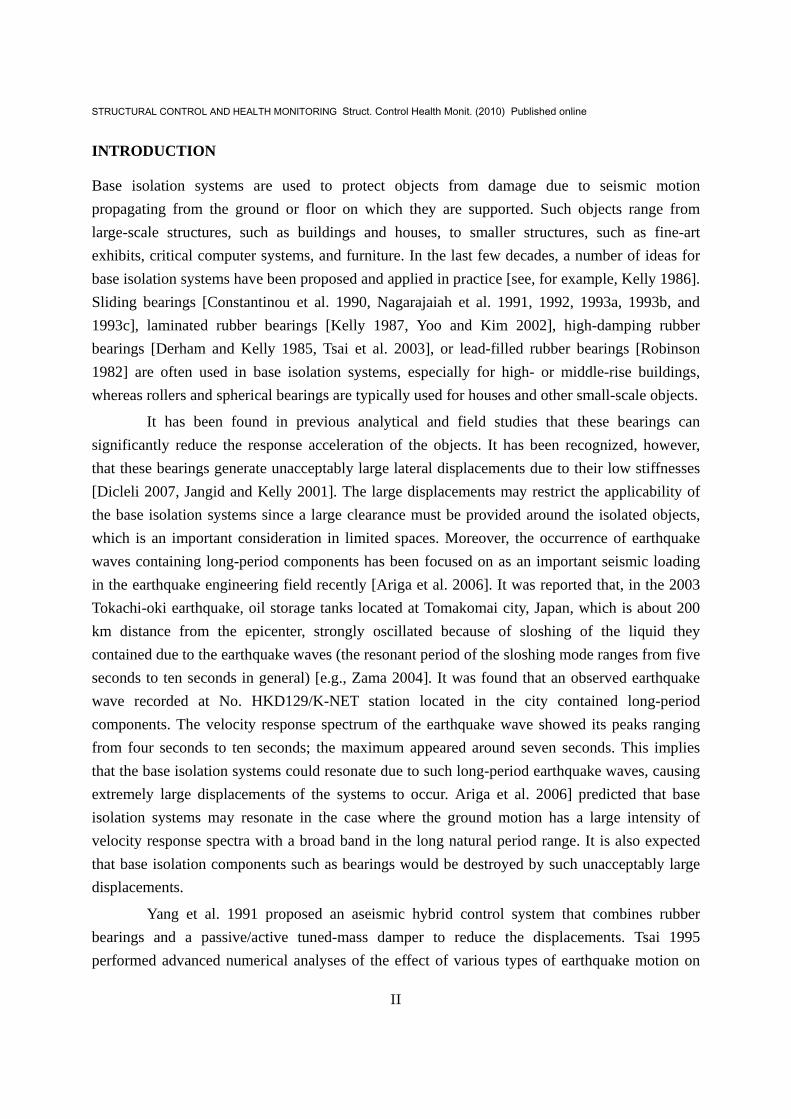
Base isolation systems are used to protect objects from damage due to seismic motion propagating from the ground or floor on which they are supported. Such objects range from large-scale structures, such as buildings and houses, to smaller structures, such as fine-art exhibits, critical computer systems, and furniture. In the last few decades, a number of ideas for base isolation systems have been proposed and applied in practice [see, for example, Kelly 1986]. Sliding bearings [Constantinou et al. 1990, Nagarajaiah et al. 1991, 1992, 1993a, 1993b, and 1993c], laminated rubber bearings [Kelly 1987, Yoo and Kim 2002], high-damping rubber bearings [Derham and Kelly 1985, Tsai et al. 2003], or lead-filled rubber bearings [Robinson 1982] are often used in base isolation systems, especially for high- or middle-rise buildings, whereas rollers and spherical bearings are typically used for houses and other small-scale objects.
It has been found in previous analytical and field studies that these bearings can significantly reduce the response acceleration of the objects. It has been recognized, however, that these bearings generate unacceptably large lateral displacements due to their low stiffnesses [Dicleli 2007, Jangid and Kelly 2001]. The large displacements may restrict the applicability of the base isolation systems since a large clearance must be provided around the isolated objects, which is an important consideration in limited spaces. Moreover, the occurrence of earthquake waves containing long-period components has been focused on as an important seismic loading in the earthquake engineering field recently [Ariga et al. 2006]. It was reported that, in the 2003 Tokachi-oki earthquake, oil storage tanks located at Tomakomai city, Japan, which is about 200 km distance from the epicenter, strongly oscillated because of sloshing of the liquid they contained due to the earthquake waves (the resonant period of the sloshing mode ranges from five seconds to ten seconds in general) [e.g., Zama 2004]. It was found that an observed earthquake wave recorded at No. HKD129/K-NET station located in the city contained long-period components. The velocity response spectrum of the earthquake wave showed its peaks ranging from four seconds to ten seconds; the maximum appeared around seven seconds. This implies that the base isolation systems could resonate due to such long-period earthquake waves, causing extremely large displacements of the systems to occur. Ariga et al. 2006] predicted that base isolation systems may resonate in the case where the ground motion has a large intensity of velocity response spectra with a broad band in the long natural period range. It is also expected that base isolation components such as bearings would be destroyed by such unacceptably large displacements.
Yang et al. 1991 proposed an aseismic hybrid control system that combines rubber bearings and a passive/active tuned-mass damper to reduce the displacements. Tsai 1995 performed advanced numerical analyses of the effect of various types of earthquake motion on

STRUCTURAL CONTROL AND HEALTH MONITORING Struct. Control Health Monit. (2010) Published online
III
multi-story buildings by means of a hybrid control system. The results of these numerical analyses showed a sufficient decrease in the displacement of base isolation systems including a passive/active tuned-mass damper. The results also indicated that a reduction of the displacement generally requires a large displacement of the mass damper, probably larger than the maximum permissible displacement amplitude of the base isolation system, since the tuned-mass damper must deal with base-isolated buildings having an extremely long fundamental period. From the viewpoint of practical application, therefore, the above aseismic hybrid control system seems to be applicable only to such large-scale structures that allow large displacements of the mass damper, whereas applying this system to small-scale objects, such as houses, fine-art exhibits, and furniture, may be difficult due to the limited space available.
In recent years, the number of patent applications for reducing the lateral displacement of base isolation systems by incorporating a gyro-mass has been increasing. The gyro-mass generates a reaction force due to the relative acceleration of the nodes between which it is placed. The primary effect of the gyro-mass is to increase the inertia of the isolated object so that the lateral displacement is restricted. From a practical point of view, the advantage of the use of the gyro-mass device is that it can be incorporated into the conventional base isolation systems without any of the control systems described above. Moreover, as described later, the gyro-mass can be constructed by a compact mechanical system that is easy to incorporate into the conventional base isolation systems. Various types of gyro-mass devices have been proposed, including a device composed of a gyro-mass arranged in parallel with a spring and a damper [e.g., Okumura 1997, Katamura et al. 2000]; and a device composed of a gyro-mass arranged in series with a unit having a spring and a damper, which are arranged in parallel [e.g., Katamura et al. 1999, Saitoh 2007]. In addition, there is a certain type of viscous damper in which an intrinsic rotary mass subsidiary behaves as a gyro-mass [Saito et al. 2004]. Such a damper is categorized as the former device with a high damping function. However, there have been few investigations into differences in the performance of these systems, especially when subjected to actually observed earthquake waves, including a long-period earthquake wave.
Accordingly, the objectives of this study are: (1) to derive closed-form formulae of the base isolation systems with three types of gyro-mass devices composed of a gyro-mass and spring/damper elements, including a proposed model that is modified to reduce lateral displacements due to long-period earthquake waves; (2) to show the resonant characteristics of the base isolation systems in the frequency domain; and (3) to show the time-history responses when subjected to simulated earthquakes, based on actually observed earthquake records.
GYRO-MASS DEVICE
STRUCTURAL CONTROL AND HEALTH MONITORING Struct. Control Health Monit. (2010) Published online
IV
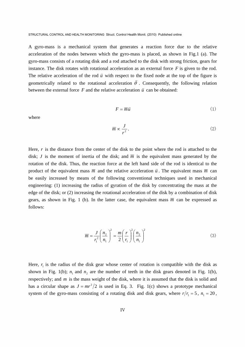
A gyro-mass is a mechanical system that generates a reaction force due to the relative acceleration of the nodes between which the gyro-mass is placed, as shown in Fig.1 (a). The gyro-mass consists of a rotating disk and a rod attached to the disk with strong friction, gears for instance. The disk rotates with rotational acceleration as an external force F is given to the rod. The relative acceleration of the rod u&& with respect to the fixed node at the top of the figure is geometrically related to the rotational acceleration θ&& . Consequently, the following relation between the external force F and the relative acceleration u&& can be obtained:
umF &&= (1)
where
2rJm ∝ . (2)
Here, r is the distance from the center of the disk to the point where the rod is attached to the disk; J is the moment of inertia of the disk; and m is the equivalent mass generated by the rotation of the disk. Thus, the reaction force at the left hand side of the rod is identical to the product of the equivalent mass m and the relative acceleration u&& . The equivalent mass m can be easily increased by means of the following conventional techniques used in mechanical engineering: (1) increasing the radius of gyration of the disk by concentrating the mass at the edge of the disk; or (2) increasing the rotational acceleration of the disk by a combination of disk gears, as shown in Fig. 1 (b). In the latter case, the equivalent mass m can be expressed as follows:
2
1
2
2
1
2
1
22
1 2 ⎟⎟⎠
⎞⎜⎜⎝
⎛⎟⎟⎠
⎞⎜⎜⎝
⎛=⎟⎟
⎠
⎞⎜⎜⎝
⎛=
nn
rrm
nn
rJm (3)
Here, 1r is the radius of the disk gear whose center of rotation is compatible with the disk as shown in Fig. 1(b); 1n and 2n are the number of teeth in the disk gears denoted in Fig. 1(b), respectively; and m is the mass weight of the disk, where it is assumed that the disk is solid and has a circular shape as 22mrJ = is used in Eq. 3. Fig. 1(c) shows a prototype mechanical system of the gyro-mass consisting of a rotating disk and disk gears, where 51 =rr , 201 =n ,

STRUCTURAL CONTROL AND HEALTH MONITORING Struct. Control Health Monit. (2010) Published online
V
and 802 =n . In this system, therefore, the equivalent mass m can be increased 200 times as large as the mass weight of the disk m . Therefore, an extremely large equivalent mass m can be produced with a small disk mass in a compact space.
FREQUENCY-DOMAIN CHARACTERISTICS OF BASE ISOLATION SYSTEM WITH GYRO-MASS DEVICE
Basic Model
The primary effect of the gyro-mass is to increase the inertia of the base-isolated object in a particular direction. A conventional base isolation system is represented by the idealized model shown in Fig. 2(a). The isolation system has lateral stiffness sk and damping sc . In this study, the base-isolated object is assumed to be a lumped mass sm . This assumption has frequently been used in recent studies [e.g. Ryan and Chopra 2004, Furukawa et al. 2005] for representing the fundamental rigid body mode of a base isolation system in earthquake vibrations. The displacement of the lumped mass sm relative to the base is denoted as u . On the other hand, a base isolation system incorporating a gyro-mass is shown in Fig. 2(b). The gyro-mass has the equivalent mass m . The response of this base isolation system when excited by ground
acceleration gu&& is governed by the following equation:
( ) 0=++++ umukucuum ssgs &&&&&&& . (4)
Eq. 4 can be rewritten as follows:
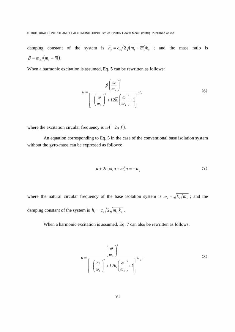
gsss uuuhu &&&&& βωω −=++ 22 (5)
where the natural circular frequency of the base isolation system is ( )mmk sss +=ω ; the
STRUCTURAL CONTROL AND HEALTH MONITORING Struct. Control Health Monit. (2010) Published online
VI
damping constant of the system is ( ) ssss kmmch += 2 ; and the mass ratio is
( )mmm ss +=β .
When a harmonic excitation is assumed, Eq. 5 can be rewritten as follows:
g
ss
s
s u
hi
u
⎥⎥⎦
⎤
⎢⎢⎣
⎡+⎟⎟
⎠
⎞⎜⎜⎝
⎛+⎟⎟
⎠
⎞⎜⎜⎝
⎛−
⎟⎟⎠
⎞⎜⎜⎝
⎛
=
122
2
ωω
ωω
ωωβ
(6)
where the excitation circular frequency is ( )fπω 2= .
An equation corresponding to Eq. 5 in the case of the conventional base isolation system without the gyro-mass can be expressed as follows:
gsss uuuhu &&&&& −=++ 22 ωω (7)
where the natural circular frequency of the base isolation system is sss mk=ω ; and the
damping constant of the system is ssss kmch 2= .
When a harmonic excitation is assumed, Eq. 7 can also be rewritten as follows:
g
ss
s
s u
hi
u
⎥⎥⎦
⎤
⎢⎢⎣
⎡+⎟⎟
⎠
⎞⎜⎜⎝
⎛+⎟⎟
⎠
⎞⎜⎜⎝
⎛−
⎟⎟⎠
⎞⎜⎜⎝
⎛
=
122
2
ωω
ωω
ωω
. (8)
STRUCTURAL CONTROL AND HEALTH MONITORING Struct. Control Health Monit. (2010) Published online
VII
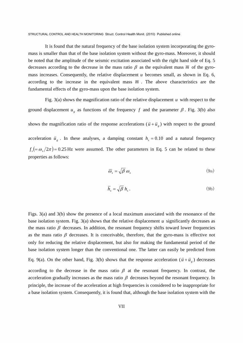
It is found that the natural frequency of the base isolation system incorporating the gyro-mass is smaller than that of the base isolation system without the gyro-mass. Moreover, it should be noted that the amplitude of the seismic excitation associated with the right hand side of Eq. 5 decreases according to the decrease in the mass ratio β as the equivalent mass m of the gyro-mass increases. Consequently, the relative displacement u becomes small, as shown in Eq. 6, according to the increase in the equivalent mass m . The above characteristics are the fundamental effects of the gyro-mass upon the base isolation system.
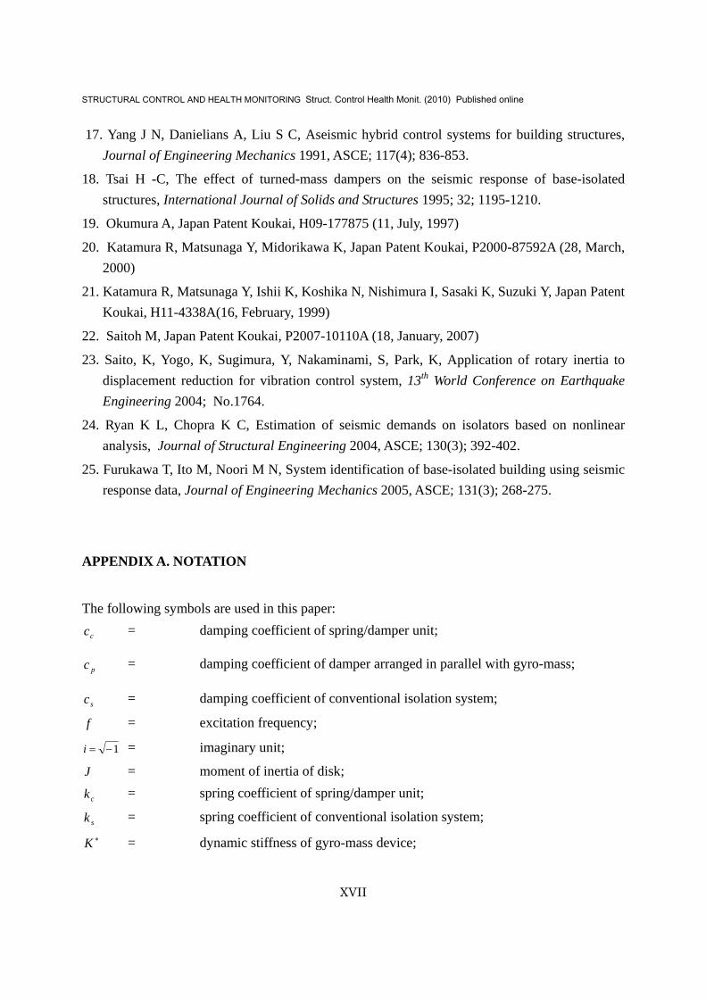
Fig. 3(a) shows the magnification ratio of the relative displacement u with respect to the
ground displacement gu as functions of the frequency f and the parameter β . Fig. 3(b) also
shows the magnification ratio of the response accelerations ( guu &&&& + ) with respect to the ground
acceleration gu&& . In these analyses, a damping constant 10.0=sh and a natural frequency
( ) 25.02 == πωssf Hz were assumed. The other parameters in Eq. 5 can be related to these properties as follows:
ss ωβω = (9a)
ss hh β= . (9b)
Figs. 3(a) and 3(b) show the presence of a local maximum associated with the resonance of the base isolation system. Fig. 3(a) shows that the relative displacement u significantly decreases as the mass ratio β decreases. In addition, the resonant frequency shifts toward lower frequencies as the mass ratio β decreases. It is conceivable, therefore, that the gyro-mass is effective not only for reducing the relative displacement, but also for making the fundamental period of the base isolation system longer than the conventional one. The latter can easily be predicted from
Eq. 9(a). On the other hand, Fig. 3(b) shows that the response acceleration ( guu &&&& + ) decreases
according to the decrease in the mass ratio β at the resonant frequency. In contrast, the acceleration gradually increases as the mass ratio β decreases beyond the resonant frequency. In principle, the increase of the acceleration at high frequencies is considered to be inappropriate for a base isolation system. Consequently, it is found that, although the base isolation system with the

STRUCTURAL CONTROL AND HEALTH MONITORING Struct. Control Health Monit. (2010) Published online
VIII
gyro-mass may reduce the relative displacement, use of the gyro-mass may interfere with the base isolation function.
Model I
Based on the above results, it was then attempted to restrict the increase of the response acceleration at higher frequencies while also decreasing the relative displacement by means of the gyro-mass. Fig. 2(c) shows a base isolation system with a gyro-mass device composed of a gyro-mass arranged in series with a unit having a spring and a damper, which are arranged in parallel. This type of modified model has also been found in practice as well as the Basic Model. This spring/damper unit may reduce the effect of the gyro-mass at higher frequencies where the effect of the base isolation should be enhanced. The reason for this is that the dynamic stiffness of the gyro-mass generally becomes larger than that of the spring/damper unit at higher frequencies since the dynamic stiffness of the gyro-mass is proportional to the square of the frequency. At higher frequencies, therefore, the displacement of the gyro-mass device is mainly generated by the spring/damper unit, and thus, the characteristics of this unit strongly influence the base isolation system.
When a steady-state excitation with circular frequency ω is assumed, the dynamic stiffness of the gyro-mass device, ∗K , composed of the gyro-mass and the spring/damper unit can be expressed by the following equation:
( )cc
cc
kicmkicm
K++−+−
=∗
ωωωω
2
2
(10)
where cc and ck are the damping coefficient and spring coefficient of the spring/damper unit, respectively.
The equilibrium equation of the system when subjected to ground acceleration gu&& can
be formulated as follows:
( ) 0=++++ ∗uKukucuum ssgs &&&&& . (11)

STRUCTURAL CONTROL AND HEALTH MONITORING Struct. Control Health Monit. (2010) Published online
IX
When a harmonic excitation is assumed, Eq. 11 can be rewritten as follows:
g
ccs
cccs
css
ss
ccs
css
u
hihihi
hi
u
⎥⎦
⎤⎢⎣
⎡+⎟⎟
⎠
⎞⎜⎜⎝
⎛⎟⎟⎠
⎞⎜⎜⎝
⎛−−
⎥⎥⎦
⎤
⎢⎢⎣
⎡+⎟⎟
⎠
⎞⎜⎜⎝
⎛+⎟⎟
⎠
⎞⎜⎜⎝
⎛−
⎥⎥⎦
⎤
⎢⎢⎣
⎡+⎟⎟
⎠
⎞⎜⎜⎝
⎛+⎟⎟
⎠
⎞⎜⎜⎝
⎛−
⎥⎥⎦
⎤
⎢⎢⎣
⎡+⎟⎟
⎠
⎞⎜⎜⎝
⎛+⎟⎟
⎠
⎞⎜⎜⎝
⎛−⎟⎟
⎠
⎞⎜⎜⎝
⎛
=22
22
222
211212
2
γγωω
βγγ
ωω
ωω
ωω
ωω
γγωω
ωω
ωω
(12)
where
c
cc km
ch
2= ,
s
cc ω
ωγ = , and
mkc
c =ω .
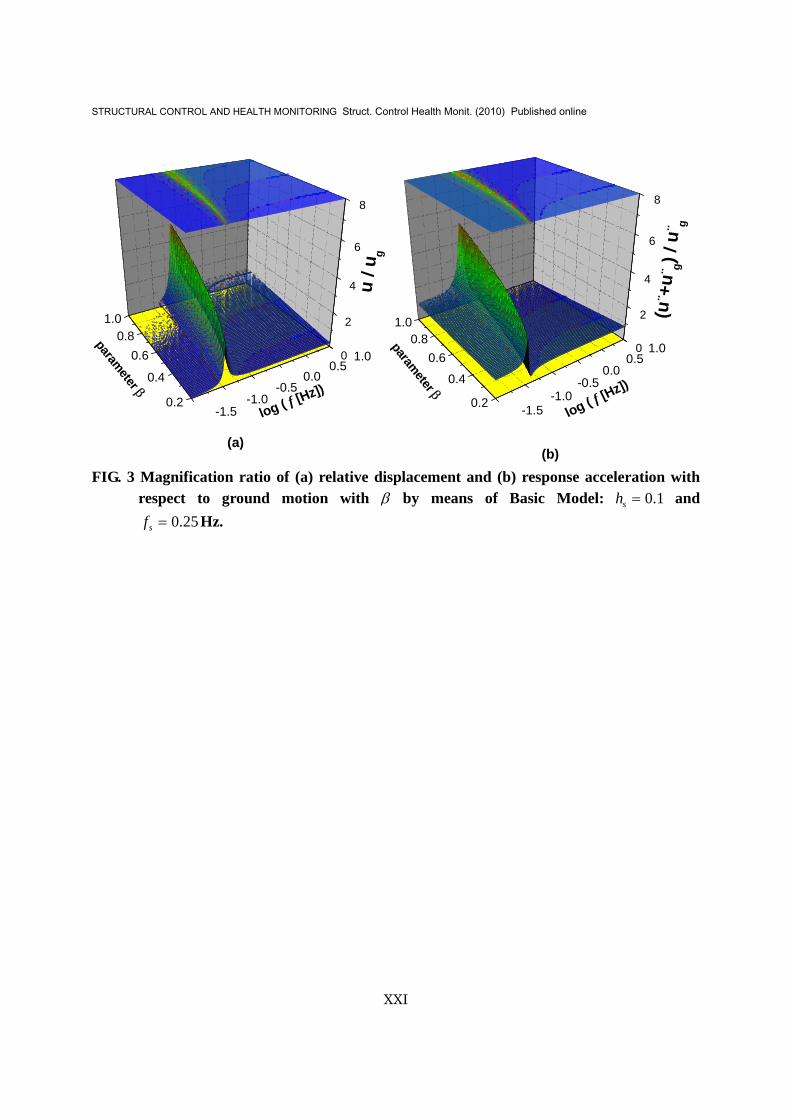
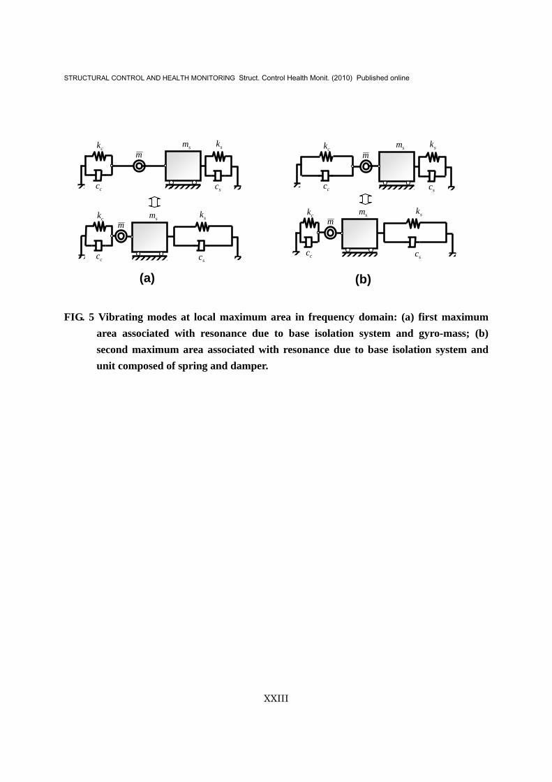
Hereinafter, the resonant characteristics of this system are evaluated based on Eq. 12. In this analysis, damping constant 20.0=ch and frequency ratio 0.1=cγ were assumed. The other properties assumed here are the same as those in Fig. 3. Fig. 4 indicates the presence of two local maximum areas, which can be more clearly identified as the mass ratio β decreases: the local maximum area at lower frequencies (referred to as the first maximum area) is associated with the resonance mainly due to the base isolation system and the gyro-mass, as illustrated in Fig. 5(a); and the local maximum area at higher frequencies (referred to as the second maximum area) is mainly due to the base isolation system and the spring/damper unit, as shown in Fig. 5(b). Herein, the vibrating modes in Fig. 5 are illustrated based on the absolute values of the deformations of the gyro-mass muΔ and the spring/damper unit uuΔ , each normalized by the total deformation of the gyro-mass device u ( um uu Δ+Δ= ) shown in Fig. 6. They are obtained by the following formulas:

STRUCTURAL CONTROL AND HEALTH MONITORING Struct. Control Health Monit. (2010) Published online
X
22
2
2
2
ccs
cs
ccs
cm
hi
hi
uu
γγωω
ωω
γγωω
+⎟⎟⎠
⎞⎜⎜⎝
⎛+⎟⎟
⎠
⎞⎜⎜⎝
⎛−
+⎟⎟⎠
⎞⎜⎜⎝
⎛
=Δ (13a)
22
2
2 ccs
cs
su
hiuu
γγωω
ωω
ωω
+⎟⎟⎠
⎞⎜⎜⎝
⎛+⎟⎟
⎠
⎞⎜⎜⎝
⎛−
⎟⎟⎠
⎞⎜⎜⎝
⎛−
=Δ (13b)
Fig. 6 shows the absolute values for the case where the mass ratio 5.0=β . The magnification
ratio of the relative displacement u with respect to the ground displacement gu as a function of
the frequency f is also shown. Fig. 6 clearly explains the illustrations in Fig. 5: the deformation of the gyro-mass becomes greater than that of the spring/damper unit in the system around the first maximum area, whereas the opposite tendency occurs around the second maximum area.
Fig. 4(a) also indicates that the relative displacement at higher frequencies is larger than that of the Basic Model shown in Fig. 3(a). Fig. 4(b) shows that the response acceleration converges to zero as the excitation frequency increases. These characteristics imply that providing the spring/damper unit in series with the gyro-mass decreases the effect of the gyro-mass at higher frequencies, as expected from the above. It is noted that the frequency above which the effect of the gyro-mass is reduced can be adjusted based on cω in terms of an appropriate property of the spring in the spring/damper unit. Fig. 4 also shows significant decreases in the relative displacement and the response acceleration at the first maximum area when compared with those of the Basic Model at the local maximum area shown in Fig. 3.
Model II - Model Proposed for Long-Period Earthquake Waves
The first maximum area may appear within the frequency region where long-period earthquake waves tend to be dominant. The first maximum area can be diminished to a large extent by using the following technique. Fig. 2(d) shows a base isolation system with a gyro-mass device that is

STRUCTURAL CONTROL AND HEALTH MONITORING Struct. Control Health Monit. (2010) Published online
XI
almost identical to Model I described above (Fig. 2(c)), except that the gyro-mass is arranged in parallel with the damper. The damper has a large effect upon the first maximum area since the first maximum area is associated with the movement of the gyro-mass; that is, the damper absorbs the seismic energy mainly generated by the gyro-mass and the base isolation system.
When a steady-state excitation with circular frequency ω is assumed, the dynamic stiffness of this gyro-mass device can be expressed by the following equation:
( )( )( ) ccp
ccp
kccimkiccim
K+++−
++−=∗
ωωωωω
2
2
(14)
where pc is the damping coefficient of the damper arranged in parallel with the gyro-mass.
The equilibrium equation of the system when subjected to ground acceleration gu&& can
be expressed by the same equation as that shown in Eq. 11. When a harmonic excitation is assumed, the relative displacement u can be written as follows:
( )
( )g
ccs
ccs
pss
ss
s u
hihifhi
fu
⎥⎥⎦
⎤
⎢⎢⎣
⎡+⎟⎟
⎠
⎞⎜⎜⎝
⎛
⎥⎥⎦
⎤
⎢⎢⎣
⎡⎟⎟⎠
⎞⎜⎜⎝
⎛+⎟⎟
⎠
⎞⎜⎜⎝
⎛−⎟⎟
⎠
⎞⎜⎜⎝
⎛−+
⎥⎥⎦
⎤
⎢⎢⎣
⎡+⎟⎟
⎠
⎞⎜⎜⎝
⎛+⎟⎟
⎠
⎞⎜⎜⎝
⎛−
⎟⎟⎠
⎞⎜⎜⎝
⎛
=2
22
2
221112 γγωωγ
ωω
ωω
βω
ωω
ωω
ωωω
(15)
where,
( ) ( ) 2
2
2 ccg
cpg
hhif γγωω
ωωω +⎟
⎟⎠
⎞⎜⎜⎝
⎛++⎟
⎟⎠
⎞⎜⎜⎝
⎛−= , and
c
pp km
ch
2= .

STRUCTURAL CONTROL AND HEALTH MONITORING Struct. Control Health Monit. (2010) Published online
XII
Fig. 7 shows the resonant characteristics of this system given by Eq. 15. The damping
constant ph is assumed to be 20.0 . The other properties of the system are identical to those
shown in Fig. 4. Fig. 7 indicates that significant decreases in the relative displacements and the response accelerations around the first maximum area can be achieved by providing the damper in parallel with the gyro-mass, as expected. Fig. 7 also shows that the damper has a slight effect upon the response of the base isolation system beyond the first maximum area because of the spring/damper unit described above. The decrease in the response of the base isolation system around the first maximum area is therefore expected to be effective for long-period earthquake waves that result in a large relative displacement that would damage components such as laminated rubber bearings, oil dampers, etc.
TIME-DOMAIN CHARACTERISTICS OF BASE ISOLATION SYSTEM WITH GYRO-MASS DEVICE
In this section, the time-history responses of the models presented above are calculated for three simulated earthquakes based on observed earthquake records in order to verify the effect of the gyro-mass devices. The equations of motion for the Basic Model and the conventional base isolation system are simply described as a one-degree-of-freedom system, as shown in Eq. 5 and Eq. 7, respectively. On the other hand, Model I and Model II are described as two-degree-of-freedom systems. Therefore, matrix representations of the equations of motion are useful for estimating the time-history responses. The equations of motion for Model I can be formulated as follows:
gsc
s
c
ss umuu
kk
uu
cc
uu
mmmmm
&&&
&
&&
&&
⎭⎬⎫
⎩⎨⎧
−=⎭⎬⎫
⎩⎨⎧⎥⎦
⎤⎢⎣
⎡+
⎭⎬⎫
⎩⎨⎧⎥⎦
⎤⎢⎣
⎡+
⎭⎬⎫
⎩⎨⎧⎥⎦
⎤⎢⎣
⎡−
−+01
00
00
2
1
2
1
2
1 (16)
where 1u and 2u are the relative displacement of the object with respect to the ground and that of the node located between the gyro-mass and the spring/damper unit, respectively (shown in Fig.

STRUCTURAL CONTROL AND HEALTH MONITORING Struct. Control Health Monit. (2010) Published online
XIII
2). This equation can be rewritten as:
( )( ) ( ) ( ) g
cs
cc
ss u
uu
uu
hh
uu
&&&
&
&&
&&
⎭⎬⎫
⎩⎨⎧
−=⎭⎬⎫
⎩⎨⎧⎥⎦
⎤⎢⎣
⎡−
+⎭⎬⎫
⎩⎨⎧⎥⎦
⎤⎢⎣
⎡−
+⎭⎬⎫
⎩⎨⎧⎥⎦
⎤⎢⎣
⎡−−−−−
01
11001
112002
1111111
2
12
2
2
1
2
1
γβω
γβω
ββββ
(17)
Likewise, the equations of motion for Model II can be expressed as follows:
gsc
s
pcp
ppss umuu
kk
uu
cccccc
uu
mmmmm
&&&
&
&&
&&
⎭⎬⎫
⎩⎨⎧
−=⎭⎬⎫
⎩⎨⎧⎥⎦
⎤⎢⎣
⎡+
⎭⎬⎫
⎩⎨⎧⎥⎦
⎤⎢⎣
⎡+−−+
+⎭⎬⎫
⎩⎨⎧⎥⎦
⎤⎢⎣
⎡−
−+01
00
2
1
2
1
2
1 (18)
This equation can also be rewritten as:
( )( )
( ) ( )( ) ( )( )
( ) gc
s
cpccp
cpcpss
uuu
uu
hhhhhh
uu
&&
&
&
&&
&&
⎭⎬⎫
⎩⎨⎧
−=⎭⎬⎫
⎩⎨⎧⎥⎦
⎤⎢⎣
⎡−
+
⎭⎬⎫
⎩⎨⎧⎥⎦
⎤⎢⎣
⎡−+−−
−−−++
⎭⎬⎫
⎩⎨⎧⎥⎦
⎤⎢⎣
⎡−−−−−
01
11001
1121121121122
1111111
2
12
2
2
1
2
1
γβω
γβγβγβγβ
ωββββ
(19)
Time-history analysis is performed by numerical integration using Newmark’s method (the linear acceleration method is used here), with a time interval tΔ of 001.0 s. The observed
earthquake records used for applying the ground acceleration gu&& to the models were as follows:
1) Kobe NS (1995), 2) El Centro NS (1940), and 3) Tomakomai EW (2003). The time histories of the earthquake records are shown in Fig. 8. The elastic acceleration response spectra of the earthquakes for 5% damping are also shown in Fig. 9. These figures exhibit the following characteristics: Kobe NS has the largest maximum amplitude; Tomakomai EW has the largest effect upon long-period systems; and El Centro NS has intermediate characteristics in terms of

STRUCTURAL CONTROL AND HEALTH MONITORING Struct. Control Health Monit. (2010) Published online
XIV
amplitude and resonance. In the time-history analyses, the properties of the models are identical to those used in the frequency-domain analyses described above.
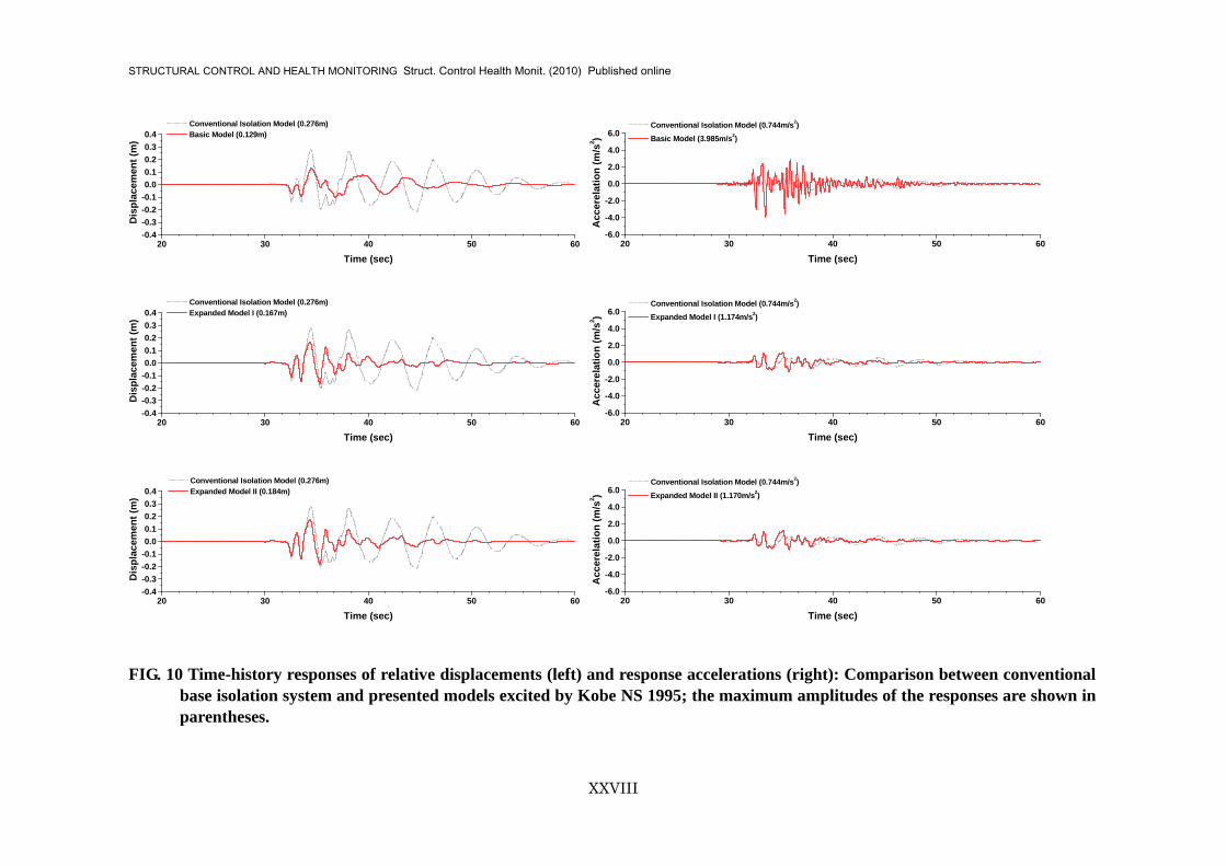
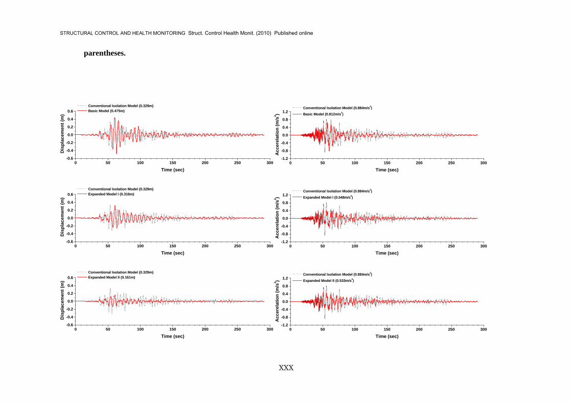
The time histories of the relative displacement 1u with respect to the ground and the
acceleration guu &&&& +1 of the base-isolated object are plotted for Kobe NS (Fig. 10), El Centro NS
(Fig. 11), and Tomakomai EW (Fig. 12), where the responses of the models using the gyro-mass devices are compared with the responses of the conventional base isolation system. The maximum amplitudes are summarized in Fig. 13. In addition, Fig. 14 shows the reduction ratio (expressed as a percentage) defined as the ratio of the maximum amplitude of the relative displacement of the models to that of the conventional base isolation system, which can be regarded as an index that demonstrates the effectiveness of the gyro-mass devices in reducing the relative displacement. Fig. 14 also shows the reduction ratio defined as the ratio of the maximum amplitude of the acceleration of the conventional base isolation system and the models to that of the earthquake records.
These figures show that providing the gyro-mass devices sufficiently reduces the relative displacements (40% decrease on average), except for the case of Tomakomai EW, which contains strong long-period components. In the case of Tomakomai EW, Fig. 12 shows that the relative displacement of Model I is almost the same as that of the conventional base isolation system, which is attributed to the resonant characteristics of the model at lower frequencies, as shown in Fig. 4. In particular, in the case of the Basic Model, the relative displacement is 40% larger than that of the conventional base isolation system due to the presence of the large local maximum at lower frequencies, as shown in Fig. 3. In contrast, Model II achieves a significant reduction (a reduction ratio of up to 50%) of the relative displacement since Model II has no local maximum at lower frequencies, as shown in Fig. 7, because of the damper arranged in parallel with the gyro-mass.
These figures also show a sufficient reduction of the accelerations (less than 1 m/s2 on average), except for the case of the Basic Model: an acceleration of about 4 m/s2 appears in the case of Kobe NS when using the Basic Model due to the resonant characteristics at higher frequencies, as explained above (also shown in Fig. 3). It is noted, therefore, that the provision of the spring/damper unit is extremely effective in restricting the increase of the acceleration at higher frequencies when the gyro-mass is employed.

STRUCTURAL CONTROL AND HEALTH MONITORING Struct. Control Health Monit. (2010) Published online
XV
CONCLUSIONS
In the present study, the following may be concluded:
1. This study investigates into the dynamic responses of base isolation systems incorporating a so called "gyro-mass" device for reducing large lateral displacements. The gyro-mass is defined as a mechanical system that generates a reaction force due to the relative acceleration of the nodes between which it is placed.
2. Three types of base isolation systems incorporating gyro-masses are focused on in this study. Equations representing their harmonic responses are presented, and the frequency-domain resonant characteristics are studied. A model proposed in this study, called "Model II", exhibits a significant decrease in the relative displacement of the object with respect to the base at low frequencies as well as almost the same decrease in the response acceleration at high frequencies as a conventional base isolation system.
3. The time-history responses are calculated for three observed earthquake records in order to verify the effect of the gyro-mass devices. Matrix representations of the equations of motion are presented. Model II shows that the relative displacement is markedly reduced even for long-period earthquake waves. Moreover, the model shows a sufficient reduction of the response acceleration, which is comparable to the conventional base isolation system.
4. A model, called "Model I", is considered to be effective for ordinary earthquake waves, whereas the model cannot sufficiently reduce the relative displacement for long-period earthquake waves. Therefore, designers need to take care of the use of this model when a certain probability of occurrence in long-period earthquake waves is expected at a site where the model is applied.
5. A model, called "Basic Model", tends to generate large response accelerations when subjected to strong ground motions due to the degradation of base isolation functions. Moreover, this model also increases large displacements of base isolation systems for long-period earthquake waves. Therefore, the performance of Base Model strongly depends on the types of earthquake waves so that designers have to pay much attention to the above characteristics when this model is applied.
References
1. Kelly J M, Aseismic base isolation: Review and bibliography, Journal of Soil Dynamics and Earthquake Engineering 1986; 5(3); 202-216.
2. Constantinou M C, Mokha A, Reinhorn A M, Teflon bearings in base isolation II: Modeling,

STRUCTURAL CONTROL AND HEALTH MONITORING Struct. Control Health Monit. (2010) Published online
XVI
Journal of Structural Engineering, ASCE 1990; 116(2); 455-474.
3. Nagarajaiah S, Reinhorn A M, Constantinou M C, Nonlinear dynamic analysis of 3D-base isolated structures, Journal of Structural Engineering, ASCE 1991; 117(7); 2035-2054.
4. Nagarajaiah S, Reinhorn A M, Constantinou M C, Experimental study of sliding isolated structures with uplift restraint, Journal of Structural Engineering, ASCE 1992; 118(6); 1666-1682.
5. Nagarajaiah S, Reinhorn A M, Constantinou M C, Torsional coupling in sliding base isolated structures, Journal of Structural Engineering, ASCE 1993; 119(1); 130-149.
6. Nagarajaiah S, Feng M Q, Shinozuka M, Control of structures with friction controllable sliding bearings, Journal of Soil Dynamics and Earthquake Engineering 1993; 12(2); 103-112.
7. Nagarajaiah S, Riley M A, Reinhorn A M, Control of sliding isolated bridges with absolute acceleration feedback, Journal of Engineering Mechanics, ASCE 1993; 119(11); 2317-2332.
8. Kelly J M, Recent developments in seismic isolation, 1987 ASME Pressure Vessels and
Piping Conference, San Diego, California 1987; PVP-127; 381-385.
9. Yoo B, Kim Y-H, Study on effects of damping in laminated rubber bearings on seismic responses for a 1/8 scale isolated test structure, Earthquake Engineering and Structural Dynamics 2002; 31; 1777-1792.
10. Derham C J, Kelly J M, Combined earthquake protection and vibration isolation, Natural Rubber Technology 1985; 16; 3-11.
11. Tsai C S, Chiang T-C, Chen B-J, Lin S-B, An advanced analytical model for high damping rubber bearings, Earthquake Engineering and Structural Dynamics 2003; 32; 1373-1387.
12. Robinson W H, Lead-rubber hysteretic bearings suitable for protecting structures during earthquakes, Earthquake Engineering and Structural Dynamics 1982; 10; 593-604.
13. Dicleli M, Supplemental elastic stiffness to reduce isolator displacements for seismic-isolated bridges in near-fault zones, Engineering Structure 2007; 29; 763-775.
14. Jangid R S, Kelly J M, Base isolation for near-fault motions, Earthquake Engineering and Structural Dynamics 2001; 30; 691-707.
15. Ariga T, Kanno Y, Takewaki I, Resonant behaviour of base-isolated high-rise buildings under long-period ground motions, Struct. Design Tall Spec. Build 2006; 15; 325–338.
16. Zama S, Seismic hazard assessment for liquid sloshing of oil storage tanks due to long-period strong ground motions in Japan, 13th World Conference on Earthquake Engineering 2004; No3200.
STRUCTURAL CONTROL AND HEALTH MONITORING Struct. Control Health Monit. (2010) Published online
XVII
17. Yang J N, Danielians A, Liu S C, Aseismic hybrid control systems for building structures, Journal of Engineering Mechanics 1991, ASCE; 117(4); 836-853.
18. Tsai H -C, The effect of turned-mass dampers on the seismic response of base-isolated structures, International Journal of Solids and Structures 1995; 32; 1195-1210.
19. Okumura A, Japan Patent Koukai, H09-177875 (11, July, 1997)
20. Katamura R, Matsunaga Y, Midorikawa K, Japan Patent Koukai, P2000-87592A (28, March, 2000)
21. Katamura R, Matsunaga Y, Ishii K, Koshika N, Nishimura I, Sasaki K, Suzuki Y, Japan Patent Koukai, H11-4338A(16, February, 1999)
22. Saitoh M, Japan Patent Koukai, P2007-10110A (18, January, 2007)
23. Saito, K, Yogo, K, Sugimura, Y, Nakaminami, S, Park, K, Application of rotary inertia to displacement reduction for vibration control system, 13th World Conference on Earthquake Engineering 2004; No.1764.
24. Ryan K L, Chopra K C, Estimation of seismic demands on isolators based on nonlinear analysis, Journal of Structural Engineering 2004, ASCE; 130(3); 392-402.
25. Furukawa T, Ito M, Noori M N, System identification of base-isolated building using seismic response data, Journal of Engineering Mechanics 2005, ASCE; 131(3); 268-275.
APPENDIX A. NOTATION
The following symbols are used in this paper:
cc = damping coefficient of spring/damper unit;
pc = damping coefficient of damper arranged in parallel with gyro-mass;
sc = damping coefficient of conventional isolation system;
f = excitation frequency;
1−=i = imaginary unit;
J = moment of inertia of disk;
ck = spring coefficient of spring/damper unit;
sk = spring coefficient of conventional isolation system; ∗K = dynamic stiffness of gyro-mass device;

STRUCTURAL CONTROL AND HEALTH MONITORING Struct. Control Health Monit. (2010) Published online
XVIII
sm = mass of base-isolated object;
m = gyro-mass coefficient;
gu&& = ground acceleration;
ω = excitation circular frequency.

STRUCTURAL CONTROL AND HEALTH MONITORING Struct. Control Health Monit. (2010) Published online
XIX
FIG. 1 Mechanical system of gyro-mass: (a) fundamental system; (b) example for increasing
rotational acceleration of disk due to combination of disk gears; (c) proto-type mechanical system of gyro-mass with disk gears.
F
u&&
rJ
θ
(a)
(b)
F1n
2n 1rJ
(c)
Rotating Disk
Rod
Disk Gears

STRUCTURAL CONTROL AND HEALTH MONITORING Struct. Control Health Monit. (2010) Published online
XX
FIG. 2 Studied models of base isolation systems: (a) conventional base isolation system; (b)
Basic Model; (c) Model I; and (d) Model II.
sc
skm
m
cc
ck
m
cc
ck
pc
sc
sk
sc
sk
sc
sk
smsm
sm
sm
(a) (b)
(c)
(d)
u
1u2u
2u 1u
u
u
u
STRUCTURAL CONTROL AND HEALTH MONITORING Struct. Control Health Monit. (2010) Published online
XXI
-1.5-1.0
-0.50.0
0.51.0
0.2
0.4
0.60.8
1.0
0
2
4
6
8
parameter β
u / u
g
log ( f [Hz])
-1.5-1.0
-0.50.0
0.51.0
0.2
0.4
0.60.8
1.0
0
2
4
6
8
parameter β
(u.. +u
.. g) /
u.. g
log ( f [Hz])
FIG. 3 Magnification ratio of (a) relative displacement and (b) response acceleration with
respect to ground motion with β by means of Basic Model: 1.0=sh and 25.0=sf Hz.
(a)(b)

STRUCTURAL CONTROL AND HEALTH MONITORING Struct. Control Health Monit. (2010) Published online
XXII
-1.5-1.0
-0.50.0
0.51.0
0.2
0.4
0.60.8
1.0
0
2
4
6
8
parameter β
u / u
g
log ( f [Hz])
-1.5-1.0
-0.50.0
0.51.0
0.2
0.4
0.60.8
1.0
0
2
4
6
8
parameter β
(u.. +u
.. g) /
u.. g
log ( f [Hz])
FIG. 4 Magnification ratio of (a) relative displacement and (b) response acceleration with
respect to ground motion with β by means of Model I: 1.0=sh , 2.0=ch , 0.1=cγ , and 25.0=sf Hz.
(a)(b)
STRUCTURAL CONTROL AND HEALTH MONITORING Struct. Control Health Monit. (2010) Published online
XXIII
FIG. 5 Vibrating modes at local maximum area in frequency domain: (a) first maximum
area associated with resonance due to base isolation system and gyro-mass; (b) second maximum area associated with resonance due to base isolation system and unit composed of spring and damper.
(a)
m
cc
ck
sc
sksm
(b)
m
cc
ck
sc
sksm
m
cc
ck
sc
sksmm
cc
ck
sc
sksm
STRUCTURAL CONTROL AND HEALTH MONITORING Struct. Control Health Monit. (2010) Published online
XXIV
-1.5 -1.0 -0.5 0.0 0.5 1.00
1
2
3 gyro-mass |Δum/u| spring/damper unit |Δuu/u| total disp. |u/ug|
Abso
lute
Val
ues
of R
atio
s
log( f [Hz] )
FIG. 6 Absolute values of the deformations of the gyro-mass and the spring/damper unit
normalized by the total deformation of the gyro-mass device with magnification ratio of displacement of gyro-mass system with respect to ground motion: 1.0=sh ,
2.0=ch , 0.1=cγ , 5.0=β and 25.0=sf Hz.

STRUCTURAL CONTROL AND HEALTH MONITORING Struct. Control Health Monit. (2010) Published online
XXV
-1.5-1.0
-0.50.0
0.51.0
0.2
0.4
0.60.8
1.0
0
2
4
6
8
parameter β
u / u
g
log ( f [Hz])
-1.5-1.0
-0.50.0
0.51.0
0.2
0.4
0.60.8
1.0
0
2
4
6
8
parameter β
(u.. +u
.. g) /
u.. g
log ( f [Hz])
FIG. 7 Magnification ratio of (a) relative displacement and (b) response acceleration with
respect to ground motion with β by means of Model II: 1.0=sh , 2.0=ch , 2.0=ph ,
0.1=cγ , and 25.0=sf Hz.
(a)(b)

STRUCTURAL CONTROL AND HEALTH MONITORING Struct. Control Health Monit. (2010) Published online
XXVI
20 30 40 50 60-10-8-6-4-202468
10 Maximum Acceleration (8.178m/s2)A
ccer
elat
ion
(m/s
2 )
Time (sec)
0 10 20 30 40 50-4-3-2-101234 Maximum Acceleration (3.147m/s2)
Acc
erel
atio
n (m
/s2 )
Time (sec)
0 50 100 150 200 250 300-1.2
-0.8
-0.4
0.0
0.4
0.8
1.2 Maximum Acceleration (0.729m/s2)
Acc
erel
atio
n (m
/s2 )
Time (sec) FIG. 8 Time histories showing observed earthquake records used for time-history analyses:
(a) Kobe NS 1995; (b) El Centro NS 1940; (c) Tomakomai EW 2003.
(a)
(b)
(c)

STRUCTURAL CONTROL AND HEALTH MONITORING Struct. Control Health Monit. (2010) Published online
XXVII
0.1 1 100.1
1.0
10.0
100.0Kobe NS 1995
El Centro NS 1940
Tomakomai EW 2003
Spe
ctra
l Acc
.(m
/s2 )
Period (sec.)
FIG. 9 Response spectra for observed earthquake records.
STRUCTURAL CONTROL AND HEALTH MONITORING Struct. Control Health Monit. (2010) Published online
XXVIII
20 30 40 50 60-0.4-0.3-0.2-0.10.00.10.20.30.4
Conventional Isolation Model (0.276m) Basic Model (0.129m)
Dis
plac
emen
t (m
)
Time (sec)
20 30 40 50 60-6.0
-4.0
-2.0
0.0
2.0
4.0
6.0 Conventional Isolation Model (0.744m/s2) Basic Model (3.985m/s2)
Acc
erel
atio
n (m
/s2 )
Time (sec)
20 30 40 50 60-0.4-0.3-0.2-0.10.00.10.20.30.4
Conventional Isolation Model (0.276m) Expanded Model I (0.167m)
Dis
plac
emen
t (m
)
Time (sec)
20 30 40 50 60-6.0
-4.0
-2.0
0.0
2.0
4.0
6.0 Conventional Isolation Model (0.744m/s2) Expanded Model I (1.174m/s2)
Acc
erel
atio
n (m
/s2 )
Time (sec)
20 30 40 50 60-0.4-0.3-0.2-0.10.00.10.20.30.4
Conventional Isolation Model (0.276m) Expanded Model II (0.184m)
Dis
plac
emen
t (m
)
Time (sec)
20 30 40 50 60-6.0
-4.0
-2.0
0.0
2.0
4.0
6.0 Conventional Isolation Model (0.744m/s2) Expanded Model II (1.170m/s2)
Acc
erel
atio
n (m
/s2 )
Time (sec)
FIG. 10 Time-history responses of relative displacements (left) and response accelerations (right): Comparison between conventional
base isolation system and presented models excited by Kobe NS 1995; the maximum amplitudes of the responses are shown in parentheses.

STRUCTURAL CONTROL AND HEALTH MONITORING Struct. Control Health Monit. (2010) Published online
XXIX
0 10 20 30 40 50-0.3
-0.2
-0.1
0.0
0.1
0.2
0.3 Conventional Isolation Model (0.155m) Basic Model (0.100m)
Dis
plac
emen
t (m
)
Time (sec)0 10 20 30 40 50
-1.5-1.0-0.50.00.51.01.52.0
Conventional Isolation Model (0.513m/s2) Basic Model (1.785m/s2)
Acc
erel
atio
n (m
/s2 )
Time (sec)
0 10 20 30 40 50-0.3
-0.2
-0.1
0.0
0.1
0.2
0.3 Conventional Isolation Model (0.155m) Expanded Model I (0.101m)
Dis
plac
emen
t (m
)
Time (sec)0 10 20 30 40 50
-1.5-1.0-0.50.00.51.01.52.0
Conventional Isolation Model (0.513m/s2) Expanded Model I (0.770m/s2)
Acc
erel
atio
n (m
/s2 )
Time (sec)
0 10 20 30 40 50-0.3
-0.2
-0.1
0.0
0.1
0.2
0.3 Conventional Isolation Model (0.155m) Expanded Model II (0.084m)
Dis
plac
emen
t (m
)
Time (sec)0 10 20 30 40 50
-1.5-1.0-0.50.00.51.01.52.0
Conventional Isolation Model (0.513m/s2) Expanded Model II (0.751m/s2)
Acc
erel
atio
n (m
/s2 )
Time (sec)
FIG. 11 Time-history responses of relative displacements (left) and response accelerations (right): Comparison between conventional
base isolation system and presented models excited by El Centro 1940; the maximum amplitudes of the responses are shown in
STRUCTURAL CONTROL AND HEALTH MONITORING Struct. Control Health Monit. (2010) Published online
XXX
parentheses.
0 50 100 150 200 250 300-0.6
-0.4
-0.2
0.0
0.2
0.4
0.6 Conventional Isolation Model (0.329m) Basic Model (0.475m)
Dis
plac
emen
t (m
)
Time (sec)0 50 100 150 200 250 300
-1.2
-0.8
-0.4
0.0
0.4
0.8
1.2 Conventional Isolation Model (0.884m/s2) Basic Model (0.812m/s2)
Acc
erel
atio
n (m
/s2 )
Time (sec)
0 50 100 150 200 250 300-0.6
-0.4
-0.2
0.0
0.2
0.4
0.6 Conventional Isolation Model (0.329m) Expanded Model I (0.316m)
Dis
plac
emen
t (m
)
Time (sec)0 50 100 150 200 250 300
-1.2
-0.8
-0.4
0.0
0.4
0.8
1.2 Conventional Isolation Model (0.884m/s2) Expanded Model I (0.548m/s2)
Acc
erel
atio
n (m
/s2 )
Time (sec)
0 50 100 150 200 250 300-0.6
-0.4
-0.2
0.0
0.2
0.4
0.6 Conventional Isolation Model (0.329m) Expanded Model II (0.161m)
Dis
plac
emen
t (m
)
Time (sec)0 50 100 150 200 250 300
-1.2
-0.8
-0.4
0.0
0.4
0.8
1.2 Conventional Isolation Model (0.884m/s2) Expanded Model II (0.533m/s2)
Acc
erel
atio
n (m
/s2 )
Time (sec)

STRUCTURAL CONTROL AND HEALTH MONITORING Struct. Control Health Monit. (2010) Published online
XXXI
FIG. 12 Time-history responses of relative displacements (left) and response accelerations (right): Comparison between conventional base isolation system and presented models excited by Tomakomai 2003; the maximum amplitudes of the responses are shown in parentheses.

STRUCTURAL CONTROL AND HEALTH MONITORING Struct. Control Health Monit. (2010) Published online
XXXII
0
0.1
0.2
0.3
0.4
0.5
0.6
Conv. Basic Model I Model II
Rel
ativ
e D
isp.
(m)
Kobe
El Centro
Tomakomai
0
1
2
3
4
5
Conv. Basic Model I Model II
Acce
lera
tion
( m/s
2 )
Kobe
El Centro
Tomakomai
FIG. 13 Maximum amplitude of response of (a) relative displacement and (b) response acceleration of conventional base isolation system and presented models.
(a) (b)

STRUCTURAL CONTROL AND HEALTH MONITORING Struct. Control Health Monit. (2010) Published online
XXXIII
0
20
40
60
80
100
120
140
160
Conv. Basic Model I Model II
Red
uctio
n R
atio
( %)
Kobe
El Centro
Tomakomai
0
20
40
60
80
100
120
140
160
Conv. Basic Model I Model II
Red
uctio
n R
atio
(%)
Kobe
El Centro
Tomakomai
FIG. 14 Reduction ratio related to (a) relative displacement and (b) response acceleration of conventional base isolation system and presented models.
(a) (b)