Run, run, run, fast and slow. Jump, jump, jump, high and low. Run and jump Like a bun.

This draft was prepared using the LaTeX style file belonging to the Journal of Fluid Mechanics 1
On the origin of the circular hydraulic jumpin a thin liquid film
Rajesh K. Bhagat1†, N. K. Jha2, P. F. Linden2 and D. Ian Wilson1
1Department of Chemical Engineering and Biotechnology, University of Cambridge, PhilippaFawcett Drive, Cambridge, CB3 0AS
2Department of Applied Mathematics and Theoretical Physics , Wilberforce Road, CambridgeCB3 0WA, UK
(Received xx; revised xx; accepted xx)
This study explores the formation of circular thin-film hydraulic jumps caused by thenormal impact of a jet on an infinite planar surface. For more than a century, it hasbeen believed that all hydraulic jumps are created due to gravity. However, we show thatthese thin-film hydraulic jumps result from energy loss due to surface tension and viscousforces alone. We show that, at the jump, surface tension and viscous forces balancethe momentum in the liquid film and gravity plays no significant role. Experimentsshow no dependence on the orientation of the surface and a scaling relation balancingviscous forces and surface tension collapses the experimental data. A theoretical analysisshows that the downstream transport of surface energy is the previously neglected criticalingredient in these flows, and that capillary waves play the role of gravity waves in atraditional jump in demarcating the transition from the supercritical to subcritical flowassociated with these jumps.
1. Introduction
It is a common experience to observe that when a jet of water falls vertically froma tap on to the base of a domestic sink, the water spreads radially outwards in a thinfilm until it reaches a radius where the film thickness increases abruptly. This abruptchange in depth is the circular hydraulic jump shown in figure 1(a). Beyond the jump,the thicker downstream liquid film then spreads until it reaches the edge of the sink.Up to this point, the hydraulic jump radius remains approximately at the same location(see supplementary video 1). Once the liquid reaches the edge of the sink, the boundarycondition for the liquid film changes, the downstream liquid film thickness increases andthe initial steady hydraulic jump radius moves inwards. In the present study, we areinterested in the steady hydraulic jump before liquid reaches the edge of the plate.
The hydraulic jump has been studied for over four hundred years. An early accountwas presented by Leonardo de Vinci in the 16th century (Hager 2013). The Italianmathematician Bidone (1819) published experimental results on the topic and Rayleigh(1914) subsequently provided the first theoretical explanation for the planar hydraulicjump based on inviscid theory.
Figures 1(b) and (c), show that the same abrupt change in film thickness occurs on avertical plane impacted by a horizontal jet and a horizontal plane impacted from belowby an upwards directed jet, respectively. Further, as can be seen in figure 1, for a given jetdiameter and flowrate, the radius of the initial jump is the same in all cases, irrespective
† Email address for correspondence: [email protected]

2 R.K. Bhagat, N.K. Jha, P.F. Linden and D.I. Wilson
(a) Horizontal surface; jetimpinging from above
(b) Vertical surface; jetimpinging horizontally
(c) Horizontal surface; jetimpinging from below
Figure 1: Hydraulic jumps caused by a water jet impinging normally on surfaces withdifferent orientations. In these three cases the jets are identical, produced from the samenozzle at the same flowrate, Q = 1 L min−1, and the radius of the jump is observed tobe independent of the orientation of the surface.
of the orientation of the surface. Thus we conclude that gravity plays no role in the initialformation of the jump.
To the best of our knowledge all existing explanations for thin-film hydraulic jumpson the scales we are considering in this paper invoke gravity as a significant force inits formation. The purpose of this paper is to show that this view is incorrect andthat the appropriate force balance in these jumps critically involves surface tension andthat gravity is unimportant. To achieve this aim we review the previous theories andexperiments in § 2. We describe our experiments in § 3, and then carry out a scalinganalysis in § 4, and show that this collapses our experimental data. We further developa detailed theory for the flow in § 5 and explain the role of surface tension in the forcebalance, and compare the theoretical predictions with the experimental data for differentsurface orientations and fluid properties in § 6. Our conclusions are given in § 7.
2. Previous studies
We are concerned here with the initiation of the jump shown by the schematic in figure2(a), so that we consider the impact of a jet normally on an infinite plane. In practice,all experiments involve a plane of finite dimensions and eventually the liquid drains fromthe edges of the surface. Consequently, we restrict ourselves to considerations of the flowbefore it reaches the edge of the surface, and ignore the changes that occur once thedownstream boundary condition changes (see supplementary video 2).
Watson (1964) developed a similarity solution for radial flow in a thin liquid film, whichwe describe further below. He also proposed the first description of a thin-film circularhydraulic jump incorporating viscous friction in the film, ignoring the tangential stressdue to surface tension, and balanced the momentum and hydrostatic pressure across thejump. Watson’s solution, which involves gravity, requires experimental measurement ofthe film thickness at the jump location to predict the jump radius, and overpredictsthe radius for smaller jumps by as much as 50%. Bush & Aristoff (2003) added surfacetension to Watson’s theory but stated that its influence was small as they argued itseffect was confined to the hoop stress associated with the increase in circumference ofthe jump. They recognised that addition of surfactant substantially (20%) increased thejump radius but they did not pursue this aspect further, owing to the complicationsinvolved with surfactants. Mathur et al. (2007) presented results for hydraulic jumps inliquid metals where the jump radii are in range of µm. They recognised that jumps on

Initiation of hydraulic jumps 3
this scale are created due to surface tension but associated with very high curvature andsmall jump radii. However, they remarked that gravity is the key to all jumps on thescale of the kitchen sink hydraulic jump.
Earlier analysis by Kurihara (1946) and Tani (1949) used thin-film boundary layerequations including gravity to model circular hydraulic jumps. This analysis was critiquedby Bohr et al. (1993) who solved the axisymmetric shallow water equations which again,naturally, include gravity. Bohr et al. (1993) found that the outer solution of the equationsbecame singular at a finite radius. Consequently, they solved the equations inwards fromthe edge of the plate or the boundary from where liquid drains due to gravity, andconnected the inner and the outer solutions for radial flow through a shock. This analysisgave a scaling relation for the jump radius R ∼ Q5/8ν−3/8g−1/8 where Q, ν and g are thejet volume flux, the kinematic viscosity of the fluid and the acceleration due to gravity,respectively. They argued that the jump could be understood qualitatively in terms ofthe interplay between gravity, viscosity and the momentum of the liquid. A similaraxisymmetric shallow water model was also proposed by Kasimov (2008). Again thisstudy did not consider the initial formation of the jump, but connected the thin filmwith a deeper flow established as a result of a downstream boundary condition at theedge of the domain.
Two studies considered the case where gravity is unimportant. Godwin (1993) assumedthe jet diameter was an important parameter and showed that the jump radius, whenindependent of gravity, scales as R ∼ Q1/3d2/3ν−1/3, where d is the jet diameter. Weargue that, since R � d, the jet diameter is not a relevant parameter. Avedisian &Zhao (2000) studied the circular hydraulic jump at low gravity in a drop tower. In theseexperiments, a horizontal plate was submerged in a pool of liquid to impose a constantdownstream liquid thickness condition and was impacted by a liquid jet to create ahydraulic jump. They found that, at normal gravity, the jump radius decreased when thedepth of the downstream liquid film increased. However, at low gravity, the downstreamliquid film height had no effect, and the jump radius increased compared to its valueunder normal gravity. Capillary waves were also observed, and they concluded that atlow gravity the jumps were dominated by viscosity and surface tension.
Hansen et al. (1997) studied surface waves in circular hydraulic jumps. They reportedthat the hydraulic jump radius scales as R ∝ Q0.77 for water, and R ∝ Q0.72 for lessviscous oils. They concluded that, on a flat plate without any reflectors, the waves aregravity-capillary waves. Further, in the limit of zero surface tension, Rojas et al. (2013)reported that R ∼ Q3/4ν−1/4H−1/2g−1/4, where H is the height of the film downstreamof the hydraulic jump.
In the experiments described below we observed that, under the same flow conditions,normal impingement of a liquid jet gives a circular hydraulic jump with the same initialradius irrespective of the orientation of the surface (figure 1). On a vertical plate, wherethe spreading liquid film and gravity are coplanar, an approximately circular hydraulicjump is still formed (figure 1(b)). The thicker liquid film beyond the hydraulic jumpthen drains downwards due to gravity and above the point of impingement the locationof the jump remains constant in time. Our experiments on a surface inclined at 45◦ alsoproduced circular jumps. A similar lack of dependence of the radius on both verticaland inclined surfaces have also been observed by Wilson et al. (2012); Wang et al.(2015); Bhagat & Wilson (2016). Similarly, when a jet impinges onto a horizontal surfacefrom below, an abrupt increase in film thickness is also observed (figure 1(c)). Underthe influence of gravity, the thicker liquid film falls as droplets or as a continuous filmforming a water bell (Jameson et al. 2010). In our experiments we changed the surfacetension of the liquid by preparing homogeneous water-alcohol solutions and a surfactant.

4 R.K. Bhagat, N.K. Jha, P.F. Linden and D.I. Wilson
Liquid label Reference T (◦C) γ (N m−1) ν(m2 s−1) ρ (kg m−3)×10−3 ×10⁻⁶
Water 20 72 1.002 1000WP95/5 (Vazquez et al. 1995) 20 42.5 1.274 989WP80/20 (Vazquez et al. 1995) 20 26 2.30 968WG30/70 (Jameson et al. 2010) 19 67 20.7 1160WG10/90 (Jameson et al. 2010) 28 65 99.3 1240
SDBS (Sun et al. 2014) 20 38 1.00 1000
Table 1: Properties of the liquids used
Supplementary video 3 shows the change in a kitchen sink scale hydraulic jump bychanging the surface tension γ when Q and ν are kept constant. The existing treatmentsare unable to explain this behaviour as they hold that surface tension only becomessignificant for much smaller jump radii.
3. Experiments
Circular hydraulic jumps were produced by impinging a liquid jet normally onto aplanar surface. Both a vertical jet impinging on a horizontal plate from above and below,and normal impingement on a vertical plate and a plate inclined at 45◦ to the horizontalwere studied. For most experiments the jet nozzle diameter was 2 mm and the jet flow rateQ varied from 0.49−2 L min−1. For low flow rates (Q < 1.3 L min−1), liquid was suppliedfrom a constant-head apparatus to glass Pasteur pipettes. For higher Q a centrifugalpump and a brass nozzle was used (Wang et al. 2015). Target plates were PerspexTM, glassor Teflon R© sheets. The horizontal plate was a 0.25 m diameter circular disk; horizontaland inclined planes consisted of a 1 × 0.4 m2 rectangular plate. It was found that thejump radius was independent of the plate material and we will not consider this factorfurther. Nozzle diameters of 1 and 3 mm were also used, and no significant difference inthe jump radius was observed when measured from the edge of the resulting jet.
The viscosity and surface tension was varied by using mixtures of water with 1-propanol(5 and 20 w/w%, labelled as WP95/5 and WP80/20, respectively) and with glycerol (70and 90 w/w% labelled WG30/70 and WG10/90, respectively ). We also used a 3 mmol L−1
solution of sodium dodecyl benzene sulfonate (SDBS) The surface tension was varied byabout a factor of three and the kinematic viscosity by a factor of nearly 100. The fluidproperties are listed in table 1.
A Photron Fastcam SA3 was used to acquire images of the liquid film and the hydraulicjump at up to 2000 fps. These were subsequently processed using MATLAB and ImageJto obtain the jump radius R as a function of the jet and fluid properties. In total over150 experiments were conducted. Error bars were determined by the standard deviationof repeated experiments.
4. Scaling analysis
We consider the axisymmetric flow shown schematically in figure 2. The jump ischaracterised by its radius R and the depth h and the radial velocity u of the film.Based on our observations we assume that gravity is unimportant and hence the flowdepends on the jet flow rate Q, the jet diameter d, the film thickness h, and the fluid
Initiation of hydraulic jumps 5
Figure 2: (a) Schematic of the liquid film and hydraulic jump created by an impingingjet. (b) Control volume of film element on which the energy balance is applied.
0 5 10 15 200.0
0.2
0.4
0.6
0.8
1.0
WG 3/7 (Glass) WG 3/7 (Teflon) WG 1/9 (Glass) Water (Vertical plate) Water (Horizontal plate) WP95/5 WP80/20 SDBSR/
R o
Q (L/min)
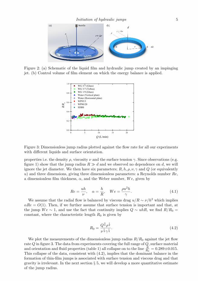
Figure 3: Dimensionless jump radius plotted against the flow rate for all our experimentswith different liquids and surface orientation.
properties i.e. the density ρ, viscosity ν and the surface tension γ. Since observations (e.g.figure 1) show that the jump radius R� d and we observed no dependence on d, we willignore the jet diameter. We then have six parameters; R, h, ρ, ν, γ and Q (or equivalentlyu) and three dimensions, giving three dimensionless parameters: a Reynolds number Re,a dimensionless film thickness, α, and the Weber number, We, given by
Re =uh
ν, α =
h
R, We =
ρu2h
γ. (4.1)
We assume that the radial flow is balanced by viscous drag u/R ∼ ν/h2 which impliesαRe = O(1). Then, if we further assume that surface tension is important and that, atthe jump We ∼ 1, and use the fact that continuity implies Q ∼ uhR, we find R/R0 =constant, where the characteristic length R0 is given by
R0 =Q
34 ρ
14
ν14 γ
14
. (4.2)
We plot the measurements of the dimensionless jump radius R/R0 against the jet flowrateQ in figure 3. The data from experiments covering the full range ofQ, surface materialand orientation and fluid properties (table 1) all collapse on to the line R
R0= 0.289±0.015.
This collapse of the data, consistent with (4.2), implies that the dominant balance in theformation of thin-film jumps is associated with surface tension and viscous drag and thatgravity is irrelevant. In the next section § 5, we will develop a more quantitative estimateof the jump radius.

6 R.K. Bhagat, N.K. Jha, P.F. Linden and D.I. Wilson
5. Theory
We consider a cylindrical co-ordinates r and z, the radial and jet-axial coordinates,respectively, u and w the associated velocity components (figure 2), and assume circularsymmetry about the jet axis. In order to analyse the jump we use the ansatz developedby Watson (1964) for the velocity within the thin film. We write the radial velocity asu = usf(η), η ≡ z/h(r) (0 6 η 6 1), where η is the dimensionless thickness of the filmand us is the velocity at the free surface. Using continuity we define the flux-averagevelocity u ≡ C1us by∫ h
0
urdz = usrh
∫ h
0
f(η)dη = C1usrh ≡ urh =Q
2π= const., (5.1)
where C1 =∫ h0f(η)dη = 0.6137 is a shape factor determined from the similarity solution.
We now balance the flux of mechanical energy across an annular control volume shownin figure 2(b), from r to r+∆r and from 0 to h (where we have cancelled out the commonfactor 2π),
(ρu2urh)
2
∣∣∣r− (ρu2urh)
2
∣∣∣r+∆r
− (γur)∣∣∣r
+ (γur)∣∣∣r+∆r
+
purh∣∣∣r− purh
∣∣∣r+∆r
+ρgurh2
2
∣∣∣r− ρgurh2
2
∣∣∣r+∆r
− rτwu∆r = 0,
(5.2)
where τw = ρν us
h f′(0) is the wall shear stress and from the velocity profile ansatz,
f ′(0) = 1.402.In these jump conditions, the first term is the flux of kinetic energy which is balanced
by pressure, gravity and viscous work given by the third, fourth and fifth terms. Theseare standard and the new term is the second term γur which represents the flux of surfaceenergy that has been neglected in previous studies. This term results from the increaseof surface area across the control volume as a result of the increase in the circumferencefrom r to r +∆r.
Dividing (5.2) by ∆r, taking the limit ∆r → 0 and using the fact that urh = constant(see (5.1)) yields,
1
2
d(ρu2)urh
dr− d(γur)
dr= −urhdp
dr− 1
2ρgurh
dh
dr− τwru. (5.3)
From the boundary layer velocity profile ansatz we write u2 =∫ 1
0u2dη ≡ C2u
2s, where
C2 ≡∫ 1
0f2(η)dη = 0.4755 is a second shape factor. Then (5.3) implies
C2ρu2shr
dusdr− γrdus
dr− γus = −usrh
dp
dr− 1
2ρgusrh
dh
dr− τwrus. (5.4)
Note that the shape factor C1 cancels out in this equation, and so plays no role. Again
using (5.1), we write usrdhdr = −hd(usr)
dr in (5.4), to obtain
(C2ρu2sh− γ −
1
2ρgrh2)r
dusdr
= −usrhdp
dr+ γus +
1
2ρgush
2 − τwrus. (5.5)
Finally, rearranging (5.5) we find that the gradient of the radial velocity satisfies
dusdr
=−usrhdpdr + γus + 1
2ρgush2 − τwrus
(1− 1We −
1Fr2 )(C2ρu2shr)
. (5.6)

Initiation of hydraulic jumps 7
Here, we define the Weber number and Froude number as, respectively,
We ≡ C2ρu2sh
γ, Fr ≡
√2C2u2sgh
. (5.7)
It is clear that (5.6) is singular when
We−1 + Fr−2 = 1, (5.8)
and that the hydraulic jump occurs where this condition is satisfied.In order to obtain quantitative results, (5.6) was solved for us using the similarly
velocity profile and the initial condition obtained from Watson (1964). The boundary
layer first occupies the full depth of the film at rb, given by rbd = 0.1833Re
13j , where
the jet Reynolds number Rej = 4Qπνd . At this location, which for the present values of
Rej ∼ 104, rb � R, us is set equal to the mean jet velocity, and (5.6) provides itssubsequent radial values. The solution of (5.6) is not sensitive to the initial conditionobtained using Watson’s similarity profile as other boundary layer velocity profiles yieldsimilar values of rb. We then calculate R as the location where We−1 + Fr−2 = 1, and(5.6) becomes singular. This condition provides a more precise estimate and a physicalbasis for the scaling argument (4.2) and also includes the effect of gravity.
6. Results
6.1. Effect of surface orientations
We showed in figure 1 that for normal jet impingement the orientation of the surfacedoes not affect the radius of the jump. In figure 1(b), for a vertical wall, the jump is veryclose to circular, which is further evidence that gravity plays no significant role. A directcomparison between the four cases of a horizontal plane impinged from above and below,a vertical plane and a surface inclined at 45◦ is shown in figure 4. The theoretical curve,obtained ignoring gravity by setting g = 0 in (5.6), agrees closely with the data from thevertical, inclined and horizontal plate from above. The observed radius is slightly largerfor the horizontal plate impinged from below. This is presumably because the ultimatetransition to dripping flow or a water bell is affected by gravity and occurs after the filminitially thickens.
6.2. Effect of fluid properties: surface tension and viscosity
Figure 5(a) compares experimental measurements with theoretical predictions of R forpure water, WP95/5 and the aqueous SDBS solution for a jet impinging on a horizontalplate from above. SDBS and pure water have similar viscosities but differ in their surfacetensions, while WP95/5 and SDBS have different viscosities but similar surface tensions.Lowering the surface tension (SDBS cf. water) increases R while increasing the viscosity(WP95/5 cf. SDBS) reduces R. The corresponding theoretical curves obtained from (5.6),again with g = 0, shown in figure 5(a), capture these variations with liquid propertiesand agree with the experimental measurements.Figure 5(b) compares data reported by Jameson et al. (2010) for liquid jets of 70 and 90w/w% glycerol/water solutions, WG30/70 and WG10/90 at 19◦C and 28◦C, respectively,impinging on the underside of a horizontal surface consisting of either glass or Teflon R©.For a given flow rate, the measured departure radius Rb is smaller for the more viscoussolution: the surface tensions are comparable. Our theoretical curves obtained by settingg = 0 in (5.6) slightly underpredict the radius, but they capture the effect of the viscosity

8 R.K. Bhagat, N.K. Jha, P.F. Linden and D.I. Wilson
0.6 0.8 1.0 1.2 1.4 1.6 1.8 2.0 2.210
15
20
25
30
35
40
45
50
55
60
Jum
p ra
dius
(mm
)
Q (L/min)
Theoretical prediction for water Vertical surface Horizontal surface, jet impinging from undersideInclined surface (45o)Horizontal surface, jet impinging from top
Figure 4: Jump radius plotted against jet flow rate for the four surface orientations. Ineach case the liquid was pure water. The theoretical prediction (dashed line) is obtainedfrom setting g = 0 in (5.6).
changes. In their theoretical description of the water bell departure radius, Button et al.(2010) expected that Rb would depend on the surface wettability or the contact anglebetween the surface and the liquid. As can be seen in figure 5(b) there is only a very smalldifference between the glass (hydrophilic) and Teflon R© (hydrophobic) surfaces. Althoughthey observed a change in the local contact angle at the rim of the radial flow, the waterbell formation radius was at the same location, as predicted by our theory.
6.3. Return to scaling
We can now use the solution to determine the constant in the scaling relation (4.2).Using (5.1), (5.7) and the expression for the wall stress we find that
R
R0=
(1
f ′(0)(2π)3C2
C21
) 14
= 0.277, (6.1)
which is close to the experimental best fit to the data 0.289±0.015 quoted in § 4.2. Thus,as expected, the theory allows us to quantify our scaling relation.
7. Conclusions
This paper provides a resolution to the question: what determines the radius of acircular hydraulic jump in a thin liquid film on an infinite plane? We derived a scalingrelationship (4.2) that collapses our data and shows that the jump location is determinedby the viscosity and the surface tension of the liquid. Using a similarity solution due toWatson (1964), with the addition of surface tension, we made quantitative predictions ofthe jump radius R that are in excellent agreement with our measurements for differentsurface orientations and fluid properties.
We found that the hydraulic jump, or the supercritical to subcritical transition, occurswhen We−1+Fr−2 = 1. From (5.6) we infer that the transport of surface energy becomesdominant for the expanding films at larger radii. The LHS of (5.5) indicates that the liquidmomentum must overcome the hydrostatic pressure and surface tension. The jump isformed where the hydrostatic pressure term ρgh2r and surface force γr are greater thanor equal to the momentum. This behaviour was previously attributed to the hydrostaticforce alone, which is a special case of the general solution.
Previous analyses have incorporated surface tension but only through the hoop stress,

Initiation of hydraulic jumps 9
0.4 0.6 0.8 1.0 1.2 1.4
10
15
20
25
30
35
40
45
Jum
p ra
dius
(mm
)
Q (L/min)
WP95/5 SDBS Water
(a) Effect of surface tension
0 5 10 15 200
20
40
60
80
100
120
140
R b (mm
)
Q (L/min)
WG3/7 (Glass) (Teflon) WG1/9 (Glass)
(b) Effect of kinematic viscosity
Figure 5: (a) Initial jump radius for normal impingement on a horizontal plate from above,for water, water-propanol (WP95/5) and SDBS. Curves are the predictions obtainedfrom solutions of (5.6). The predictions lie within the uncertainty in the experimentalmeasurements; (b) Measured water bell departure radius, from Jameson et al. (2010),alongside predictions (curves), obtained by solving (5.6) with g = 0. The liquids werewater-glycerol mixtures WG30/70 and WG10/90.
which, we agree, is small on the scale of these jumps and is effectively incorporated inthe pressure term in (5.2). It is the loss of energy associated with the radial transportof surface energy that implies that the flow can no longer provide the kinetic energy tomaintain the thin film. At this point the flow decelerates rapidly, the depth of the flowincreases and the hydraulic jump occurs. This is equivalent to the surface tension forceassociated with curvature of a film of thickness h, and hence this thickness is the relevantlength scale in the Weber number used to obtain the scaling relation (4.2). Comparing ourscaling relation (4.2), R ∼ ρ1/4Q3/4ν−1/4γ−1/4, with the result obtained by Rojas et al.(2013) in the limit of zero surface tension, R ∼ Q3/4ν−1/4H−1/2g−1/4, implies that the
depth of liquid downstream of the jump scales with capillary length scale H ∼ (γ/gρ)1/2
.
It is also worth noting that the dependence of R on Q and ν our scaling relation(Q3/4ν−1/4) is very similar to that obtained by Bohr et al. (1993) quoted in § 2, namely,Q5/8ν−3/8. Consequently, these and other authors were able to fit their data to the latterscaling which involves gravity and not surface tension, since these latter two parameterswere not changed between experiments. Similarly, Hansen et al. (1997) found empiricallythat the jump radius for water, R ∝ Q0.77 which is close to our scaling relationship,R ∝ Q3/4. However, they concluded that it is consistent with the scaling relation obtainedby Bohr et al. (1993), which predicts R ∝ Q5/8.
The critical Weber number based on the film thickness at the jump implies that theflow speed is
√γ/ρh, which is the speed of capillary waves with wavenumbers comparable
to the inverse of the film thickness. Consequently, capillary waves play a similar role inthis situation to gravity waves in the traditional hydraulic jump.
It should again be emphasised that we are only concerned with the location of the jumpon an infinite plane. For vertical jet impingement on a horizontal surface, the liquid filmeventually reaches and flows off the edge of the surface. At that point there will be anotherboundary condition resulting from this flow off the edge which will result in informationtravelling upstream through the subcritical region to the initial jump location. This willeffectively flood that control and, in general, the jump will move inwards from its initiallocation, reducing R.
Finally, it is worth considering what constitutes a thin film in this context. As shown

10 R.K. Bhagat, N.K. Jha, P.F. Linden and D.I. Wilson
in § 4.2, balancing the deceleration with the viscous drag implies that the film aspectratio α ∼ Re−1. For the values of Re ∼ 1000 in our experiments h ∼ R.10−3 ∼ 100 µm.
Acknowledgement
Funding for RKB from the Commonwealth Scholarship Commission is gratefullyacknowledged. NKJ acknowledges the support of an EPSRC grant EP/K50375/1.
REFERENCES
Avedisian, C.T. & Zhao, Z. 2000 The circular hydraulic jump in low gravity. In Proc R SocLond A Math Phys Sci , , vol. 456, pp. 2127–2151. The Royal Society.
Bhagat, R.K. & Wilson, D.I. 2016 Flow in the thin film created by a coherent turbulentwater jet impinging on a vertical wall. Chem Eng Sci 152, 606–623.
Bidone, G. 1819 Le remou et sur la propagation des ondes. Report to Academie Royale desSciences de Turin, seance 12, 21–112.
Bohr, T., Dimon, P. & Putkaradze, V. 1993 Shallow-water approach to the circularhydraulic jump. J. Fluid Mech. 254, 635–648.
Bush, J.W.M. & Aristoff, J.M. 2003 The influence of surface tension on the circular hydraulicjump. J. Fluid Mech. 489, 229–238.
Button, E.C., Davidson, J. F., Jameson, G.J. & Sader, J. E. 2010 Water bells formed onthe underside of a horizontal plate. part 2. theory. J. Fluid Mech. 649, 45–68.
Godwin, R. P. 1993 The hydraulic jump (shocksand viscous flow in the kitchen sink). Am. J.Phys. 61 (9), 829–832.
Hager, W. H. 2013 Energy dissipators and hydraulic jump, , vol. 8. Springer Science & BusinessMedia.
Hansen, S. H., Hørluck, S, Zauner, D., Dimon, P., Ellegaard, C. & Creagh, S. C. 1997Geometric orbits of surface waves from a circular hydraulic jump. Phys. Rev. E 55 (6),7048.
Jameson, G. J., Jenkins, C. E., Button, E. C. & Sader, J. E. 2010 Water bells formedon the underside of a horizontal plate. part 1. experimental investigation. J. Fluid Mech.649, 19–43.
Kasimov, A. R. 2008 A stationary circular hydraulic jump, the limits of its existence and itsgasdynamic analogue. J. Fluid Mech. 601, 189–198.
Kurihara, M. 1946 On hydraulic jumps. Proceedings of the Report of the Research Institutefor Fluid Engineering, Kyusyu Imperial University 3 (2), 11–33.
Mathur, M., DasGupta, R., Selvi, N. R., John, N. S., Kulkarni, G. U. & Govindarajan,R. 2007 Gravity-free hydraulic jumps and metal femtoliter cups. Phys. Rev. Lett. 98 (16),164502.
Lord Rayleigh 1914 On the theory of long waves and bores. Proc. R. Soc. Lond. A 90 (619),324–328.
Rojas, N., Argentina, M. & Tirapegui, E. 2013 A progressive correction to the circularhydraulic jump scaling. Phys. Fluids 25 (4), 042105.
Sun, N., Shi, L., Lu, F., Xie, S. & Zheng, L. 2014 Spontaneous vesicle phase formation bypseudogemini surfactants in aqueous solutions. Soft Matter 10 (30), 5463–5471.
Tani, I. 1949 Water jump in the boundary layer. J. Phys. Soc. Jpn. 4 (4-6), 212–215.Vazquez, G., Alvarez, E. & Navaza, J. M. 1995 Surface tension of alcohol water+ water
from 20 to 50. degree. c. J. Chem. Eng. Data 40 (3), 611–614.Wang, T., Davidson, J. F. & Wilson, D. I. 2015 Flow patterns and cleaning behaviour of
horizontal liquid jets impinging on angled walls. Food Bioprod. Process. 93, 333–342.Watson, E. J. 1964 The radial spread of a liquid jet over a horizontal plane. J. Fluid Mech.
20 (3), 481–499.Wilson, D. I., Le, B. L., Dao, H. D. A., Lai, K. Y., Morison, K. R. & Davidson, J. F.
2012 Surface flow and drainage films created by horizontal impinging liquid jets. ChemEng Sci 68 (1), 449–460.


![[moves] - Neo-Arcadianeo-arcadia.com/neoencyclopedia/garou_mark_of_the_wolves_moves.pdf · close Tai-otoshi jump close Tai-hineri Command Moves then quickly jump Super Jump jump on](https://static.fdocuments.in/doc/165x107/5c11acf309d3f2b60f8c601d/moves-neo-arcadianeo-close-tai-otoshi-jump-close-tai-hineri-command-moves.jpg)