RPW Shockwave Therapy Scientific Literature Clinical Evidence
32nd URSI GASS, Montreal, 19–26 August 2017
On the Influence of the Antenna RPW/Solar Orbiter Tilt Angle and Thermal Bending to the RadioDirection Finding Capabilities
Vratislav Krupar*(1)(2), Milan Maksimovic(3), Mykhlaylo Panchenko(4), Oksana Kruparova(2), Ondrej Santolik(2)(5), and JanSoucek(2)
(1) Heliospheric Physics Laboratory, NASA Goddard Space Flight Center, Greenbelt, Maryland, USA(2) Institute of Atmospheric Physics CAS, Prague, Czech Republic
(3) LESIA, UMR CNRS 8109, Observatoire de Paris, Meudon, France(4) Space Research Institute, Austrian Academy of Sciences, Graz, Austria
(5) Faculty of Mathematics and Physics, Charles University, Prague, Czech Republic
Abstract
Solar Orbiter is a future spacecraft dedicated to solar andheliospheric physics scheduled for launch in October 2018.The Radio Plasma Waves (RPW) instrument will measureelectric fields at high time resolution using three electricantennas mounted on booms in a perpendicular plane to thespacecraft-Sun axis. Effective antenna lengths and direc-tions will be different from the physical ones due to theirthermal bending and coupling with the spacecraft body.This paper discusses the variations of the RPW’s directionfinding capability for interplanetary solar radio emissionsas a function of the distance from the Sun.
1 Introduction
Figure 1. The Solar Orbiter model with thermal bendedantennas.
Solar Orbiter is an M-class mission in the ESA ScienceProgramme Cosmic Vision 2015 – 2025, which will havea highly elliptic orbit ranging from 0.9 au at aphelion to0.28 au at perihelion [1]. The Radio Plasma Waves (RPW)instrument aboard will provide new insights into the micro-scale phenomenon, the propagation modes of the radio
waves, and the localization of their source regions. Due tohigh requirements on the low frequency electric field mea-surements demanding equal illuminations of the three an-tennas (each ∼ 6 m), the latter will be coplanar, limitingthus the possibilities of the direction finding analysis. Com-puter simulations suggest that the electric coupling with thespacecraft body will result in tilted effective antenna direc-tions of 12◦ towards the Sun, which would be sufficient fora precise direction finding analysis of interplanetary solarradio emissions. However, the influence of thermal bendingwill be in the opposite direction (Figure 1). This effect willresults in the antenna tip offset away from the Sun rangingbetween 0.5 m and 1.5 m at aphelion and perihelion, re-spectively (Figure 2). The radio direction finding analysiswill be thus more inaccurate for closer distances from theSun. Here, we provide estimates on the wave direction errorwith respect to the distance from the Sun and an uncertaintyon the receiver gain.
Figure 2. Estimated thermal antenna bending as a functionof distance from the Sun.
2 Discussion and Results
To study a possible accuracy of the Solar Orbiter/RPW’sdirection finding capability we use a relation between
measured auto and cross-correlations of signal from threemonopole antennas (Pi j) and properties of an incident elec-tromagnetic wave derived by Ladreiter et al. [2]:
Pi j =Z0 Ghih j S0
2[(1+Q)AiA j −U(AiB j +A jBi)+
(1−Q)BiB j + ıV (−AiB j +A jBi)], (1)
Ak = −sinθk cosθ cos(φ −φk)+ cosθk sinθ , (2)
Bk = −sinθk sin(φ −φk). (3)
The right hand side of equation (1) contains the impedanceof free space (Z0); the parameters of the electrical antennas:effective lengths (hk), directions (θk and φk in spherical co-ordinates) and gain (G); and incident wave properties: thewave vector directions (θ and φ in spherical coordinates),the Stokes parameters: the energy flux S0, the linear po-larization degrees Q and U , and the circular polarizationdegree V . Ak and Bk represent projections of the effectiveantenna vector on the wave plane axes.
We modeled the auto and cross-correlations Pi j betweenthree monopole antennas using equations (1 – 3), whichrepresent an unpolarized wave (Stokes parameters: Q = 0,U = 0, and V = 0) propagating from a point source locatedon the Sun (a wave vector direction: θ = 90◦, and φ = 0◦),that correspond to properties of interplanetary solar radioemissions. Effective antenna parameters for various dis-tances from the Sun have been estimated by computer sim-ulations.We have performed simulations for each set of pa-rameters considering an uncertainty on the receiver gain be-tween 0.1 and 1 dB by applying the Gaussian noise on thefinal auto/cross-correlation products (normal distributionsof the uncertainties in dB centered at 0 dB). The wave vec-tor directions have been then calculated using the SingularValue Decomposition (SVD) method [3, 4]. This way wehave simulated an angle difference between an input wavevector direction and an output one obtained by SVD.
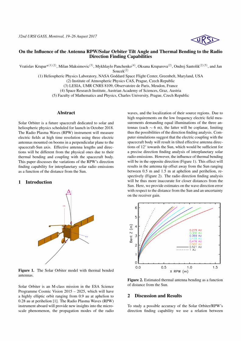
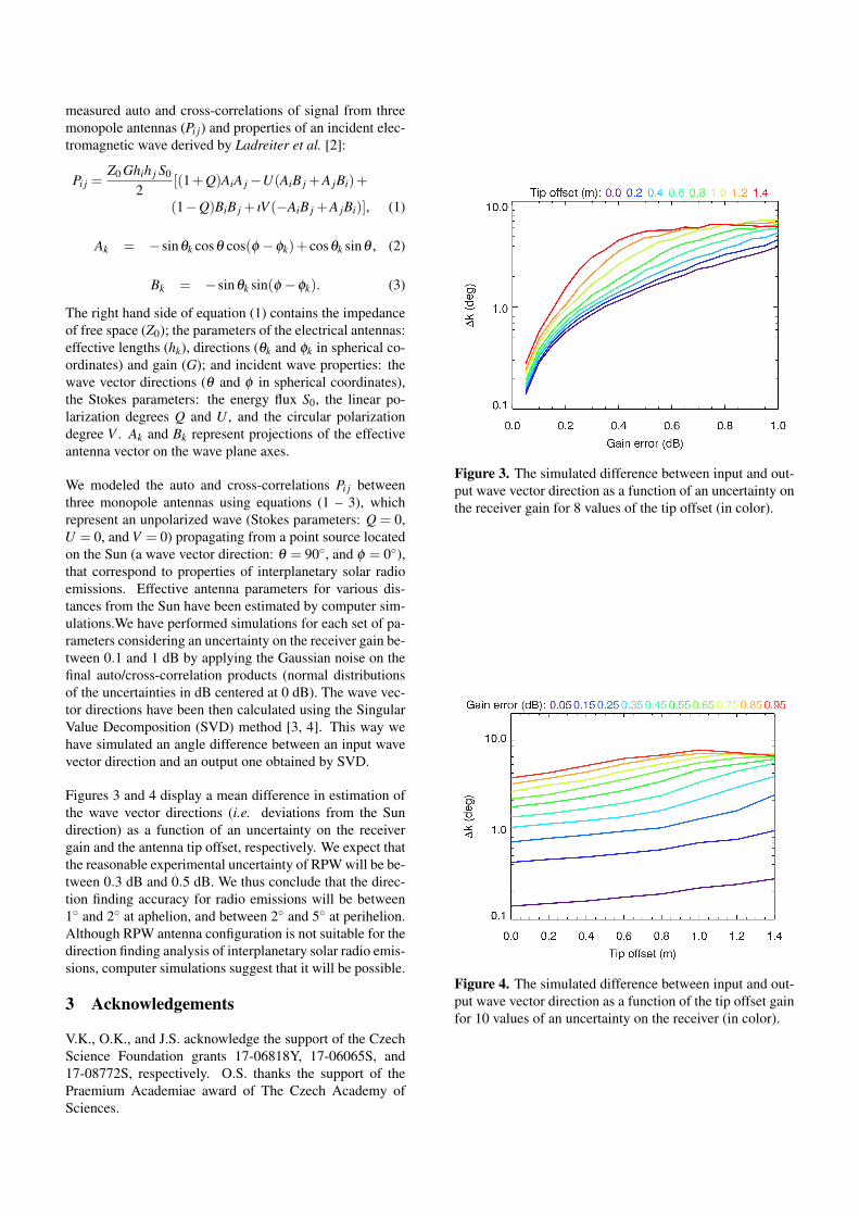
Figures 3 and 4 display a mean difference in estimation ofthe wave vector directions (i.e. deviations from the Sundirection) as a function of an uncertainty on the receivergain and the antenna tip offset, respectively. We expect thatthe reasonable experimental uncertainty of RPW will be be-tween 0.3 dB and 0.5 dB. We thus conclude that the direc-tion finding accuracy for radio emissions will be between1◦ and 2◦ at aphelion, and between 2◦ and 5◦ at perihelion.Although RPW antenna configuration is not suitable for thedirection finding analysis of interplanetary solar radio emis-sions, computer simulations suggest that it will be possible.
3 Acknowledgements
V.K., O.K., and J.S. acknowledge the support of the CzechScience Foundation grants 17-06818Y, 17-06065S, and17-08772S, respectively. O.S. thanks the support of thePraemium Academiae award of The Czech Academy ofSciences.
Figure 3. The simulated difference between input and out-put wave vector direction as a function of an uncertainty onthe receiver gain for 8 values of the tip offset (in color).
Figure 4. The simulated difference between input and out-put wave vector direction as a function of the tip offset gainfor 10 values of an uncertainty on the receiver (in color).

References
[1] Müller, D., Marsden, R.G., St. Cyr, O.C., and TheSolar Orbiter Team., "Solar Orbiter Exploring theSun–Heliosphere Connection,” Solar Physics, 285,25, 2013, doi: 10.1007/s11207-012-0085-7.
[2] Ladreiter, H. P., P. Zarka, A. Lecacheux, W. Macher,H. O. Rucker, R. Manning, D. A. Gurnett, and W.S. Kurth, "Analysis of electromagnetic wave direc-tion finding performed by spaceborne antennas usingsingular-value decomposition techniques," Radio Sci-ence, 30, 1699, 1995, doi:10.1029/95RS02479.
[3] Krupar, V., Santolik, O., Cecconi, B., Maksi-movic, M., Bonnin, X., Panchenko, M., Zaslavsky,A., "Goniopolarimetric inversion using SVD: Anapplication to type III radio bursts observed bySTEREO," J. Geophys. Res., 117, 6101, 2012, doi:10.1029/2011JA017333.
[4] Santolik, O., Parrot, M., Lefeuvre, F., "Singularvalue decomposition methods for wave propaga-tion analysis," Radio Science, 38, 1010, 2003, doi:10.1029/2000RS002523.