On the Influence of Ferroelectric Polarization States on ... · On the Influence of Ferroelectric...
15
TECHNISCHE MECHANIK, 36, 1-2, (2016), 73 – 87 submitted: September 07, 2015 On the Influence of Ferroelectric Polarization States on the Magneto-electric Coupling in Two-phase Composites M. Labusch, M.-A. Keip, V.V. Shvartsman, D.C. Lupascu, J. Schr¨ oder Of particular attention in a variety of novel technical applications is the coupling between magnetic and electric field quantities. Materials that show magneto-electric (ME) coupling could enable new smart devices in the area of electric-field-controlled magnetic-data storage or highly sensitive magnetic-field sensors. In general, ME ma- terials exhibit both a spontaneous magnetization and a spontaneous polarization. In this respect, they feature two ferroic states at the same time and are thus termed magneto-electric multiferroics. However, all natural and most of the synthesized ME multiferroics do not show an interaction between magnetization and electric polarization in the technically relevant temperature range. Thus, there is need for alternative realizations for ME coupling materials. A promising idea lies in the design and manufacturing of ME composites. These materials consist of a magnetostrictive and a piezoelectric phase and generate the ME coupling as a strain-induced product property. Since there exists a wealth of stable magnetostrictive and piezoelectric materials at ambient temperature, such composites yield the desired ME coupling also in a technically useful temperature range. In any case, the effec- tive ME coupling is driven by microscopic interactions between the individual phases and thus highly depends on the microstructure of the composite. This calls for powerful homogenization methods that are able to predict the effective coupling for arbitrary microstructural morphologies. Motivated by that, we apply a two-scale compu- tational homogenization framework for magneto-electro-mechanically coupled boundary value problems, which allows us to analyze the ME composite structures and calculate the effective ME-coefficient. Furthermore, by us- ing a non-linear ferroelectric material model on the micro-level, we are able to simulate the polarization process of the ferroelectric phase. We show that this has a significant impact on the obtainable ME-coefficient. 1 Introduction Materials with ferroelectric or ferromagnetic properties are used in many fields of technology. A combination of both properties in a single material, enable new applications such as electrical magnetic-field sensors or electric- write/magnetic-read memories, see for example Eerenstein et al. (2006), Spaldin and Fiebig (2005) and Bibes and Barth´ el´ emy (2008). Such materials, which combine polarization and magnetization, are known as magneto- electric (ME) multiferroics. However, all natural and most of the synthetic single-phase ME multiferroics show ME coupling only outside a technical useful temperature range, see Table 1 for an overview of measured ME coefficients. Table 1: Measured ME coefficients of single-phase materials. Material ME coefficient Temperature Reference LiCoPO 4 30.60 · 10 −12 s/m 4.2K Rivera (1994) Cr 2 O 3 4.17 · 10 −12 s/m 270.0K Vaz et al. (2010) Cr 2 O 3 4.13 · 10 −12 s/m 263.0K Rivera (1994) Cr 2 O 3 1.43 · 10 −12 s/m 293.2K Astrov (1961) BiFeO 3 0.52 · 10 −12 s/m 18.0K Rivera and Schmid (1997) Mn 3 B 7 O 13 I 9.50 · 10 −14 s/m 4.2K Crottaz et al. (1997) The disadvantage of a vanishing ME coupling coefficient at room temperature, which is not feasible for technical applications, could be circumvented by manufacturing magneto-electric composites, which consist of a piezoelec- tric and a magnetostrictive phase, see Nan (1994); Fiebig (2005) and Hill (2000). In such composites, the individual phases interact with one another mechanically, so that a strain-induced ME coupling (even at ambient tempera- ture) can be produced. The resulting effective ME couplings, which are not present in each of the constituents, 73
Transcript of On the Influence of Ferroelectric Polarization States on ... · On the Influence of Ferroelectric...

TECHNISCHE MECHANIK,36, 1-2, (2016), 73 – 87
submitted: September 07, 2015
On the Influence of Ferroelectric Polarization States on theMagneto-electric Coupling in Two-phase Composites
M. Labusch, M.-A. Keip, V.V. Shvartsman, D.C. Lupascu, J. Schroder
Of particular attention in a variety of novel technical applications is the coupling between magnetic and electricfield quantities. Materials that show magneto-electric (ME) coupling could enable new smart devices in the areaof electric-field-controlled magnetic-data storage or highly sensitive magnetic-field sensors. In general, ME ma-terials exhibit both a spontaneous magnetization and a spontaneous polarization. In this respect, they feature twoferroic states at the same time and are thus termed magneto-electric multiferroics. However, all natural and mostof the synthesized ME multiferroics do not show an interaction between magnetization and electric polarizationin the technically relevant temperature range. Thus, thereis need for alternative realizations for ME couplingmaterials. A promising idea lies in the design and manufacturing of ME composites. These materials consist ofa magnetostrictive and a piezoelectric phase and generate the ME coupling as a strain-induced product property.Since there exists a wealth of stable magnetostrictive and piezoelectric materials at ambient temperature, suchcomposites yield the desired ME coupling also in a technically useful temperature range. In any case, the effec-tive ME coupling is driven by microscopic interactions between the individual phases and thus highly depends onthe microstructure of the composite. This calls for powerful homogenization methods that are able to predict theeffective coupling for arbitrary microstructural morphologies. Motivated by that, we apply a two-scale compu-tational homogenization framework for magneto-electro-mechanically coupled boundary value problems, whichallows us to analyze the ME composite structures and calculate the effective ME-coefficient. Furthermore, by us-ing a non-linear ferroelectric material model on the micro-level, we are able to simulate the polarization processof the ferroelectric phase. We show that this has a significant impact on the obtainable ME-coefficient.
1 Introduction
Materials with ferroelectric or ferromagnetic propertiesare used in many fields of technology. A combination ofboth properties in a single material, enable new applications such as electrical magnetic-field sensors or electric-write/magnetic-read memories, see for example Eerensteinet al. (2006), Spaldin and Fiebig (2005) and Bibesand Barthelemy (2008). Such materials, which combine polarization andmagnetization, are known asmagneto-electric (ME) multiferroics. However, all natural and most of the synthetic single-phase ME multiferroics showME coupling only outside a technical useful temperature range, see Table 1 for an overview of measured MEcoefficients.
Table 1: Measured ME coefficients of single-phase materials.
Material ME coefficient Temperature Reference
LiCoPO4 30.60·10−12 s/m 4.2 K Rivera (1994)Cr2O3 4.17·10−12 s/m 270.0 K Vaz et al. (2010)Cr2O3 4.13·10−12 s/m 263.0 K Rivera (1994)Cr2O3 1.43·10−12 s/m 293.2 K Astrov (1961)BiFeO3 0.52·10−12 s/m 18.0 K Rivera and Schmid (1997)Mn3B7O13I 9.50·10−14 s/m 4.2 K Crottaz et al. (1997)
The disadvantage of a vanishing ME coupling coefficient at room temperature, which is not feasible for technicalapplications, could be circumvented by manufacturing magneto-electric composites, which consist of a piezoelec-tric and a magnetostrictive phase, see Nan (1994); Fiebig (2005) and Hill (2000). In such composites, the individualphases interact with one another mechanically, so that astrain-inducedME coupling (even at ambient tempera-ture) can be produced. The resulting effective ME couplings, which are not present in each of the constituents,
73
lenz
Texteingabe
DOI: 10.24352/UB.OVGU-2017-011

are classified asproduct properties. We distinguish between the direct and the inverse ME effect. The direct cou-pling effect characterizes magnetically induced polarization: an applied magnetic field yields a deformation of themagneto-active phase which is transferred to the electro-active phase. As a result, a strain-induced polarization inthe electro-active phase is observed, see Figure 1. The converse effect is characterized by an electric-field inducedmagnetization. Several experiments on ME composites showed remarkable ME coefficients, which are orders ofmagnitudes higher than those of single-phase multiferroics, see, for example, Fiebig (2005).Due to the microscopic interactions between the individualphases, the arising ME coefficient strongly depends onthe microstructure of the composite. Motivated by that, we recapitulate a two-scale finite element homogenizationframework (FE2-method) for magneto-electro-mechanically coupled boundary value problems, see Schroder et al.(2015a). This allows for the consideration of microscopic morphologies in a macroscopic simulation. In the con-text of multiscale homogenization we refer to Miehe and Koch(2002), Miehe and Bayreuther (2007), Geers et al.(2010) as well as to recent extensions to coupled material response Miehe et al. (2011), Schroder and Keip (2012),Zah and Miehe (2013), Labusch et al. (2014), Keip et al. (2014)or Schroder et al. (2015b).Obviously, the polarization state of the ferroelectric phase strongly influences the ME coupling. The reason for thatis that in a bulk composite the electro-mechanical couplingof the ferroelectric phase has to be poled in order toallow for significant strain-induced interactions. The pre-polarization is thus crucial in the manufacturing and thedesign of ME composites. At this point we want to refer to Avakian et al. (2015), where the authors used a nonlin-ear ferroelectric model to simulate the magneto-electric coupling in composite materials regarding the polarizationof the electric matrix. In order to map this in our simulations, we consider a non-linear hysteretic material modelfor the ferroelectric phase on the microscopic level. This non-linear model is based on a microscopic switchingcriterion for the spontaneous polarization based on the work of Hwang et al. (1995). The material model will becombined with a magneto-electric enthalpy function which reflects the tetragonal symmetry of a barium titanateunit cell, compare to Keip and Schroder (2011); Keip and Schroder (2011) or Keip (2012).
∆H
∆ε
∆ε
∆P
a)
∆E
∆ε
∆ε
∆M
b)
Figure 1: a) Direct coupling effect and b) inverse coupling effect, see Schroder et al. (2015a).
The outline of this contribution is as follows. In the secondsection, the main ingredients of the coupled finiteelement homogenization approach will be discussed briefly.We further describe the used non-linear materialmodel reflecting the ferroelectric switching behavior. Section three then gives a numerical example, in which theinfluence of the microscopic switching behavior on obtainable ME-coefficients is analyzed. The results will becompared to experimental measurements. In section four a conclusion is given.
2 Multiscale Homogenization of ME Composites
In this section the two-scale homogenization framework formagneto-electro-mechanically coupled boundary valueproblems will be described briefly. We start with the definition of the kinematic quantities and the fundamentalbalance equations on the macroscale. The connection to the microscale is established by a localization step. Thesubsequent homogenization step yields the effective properties including the desired ME coefficient. After that,the used material models on the microscopic level will be described. We employ a linear and transversely isotropicmaterial model for the magneto-active phase and a non-linear hysteretic model for the electro-active phase. Inorder to simplify the readability of this section we summarize the basic magneto-electro-mechanical quantities inTable 2. All macroscopic quantities are denoted by an overline.
74

Table 2: Magneto-electro-mechanical quantities and theirunits.
micro- and macro-Symbol Continuum mechanical description SI-Unit
u, u displacement vector mε, ε linear strain tensor 1σ , σ Cauchy strain tensor kg/s2 m (N/m2)t, t traction vector kg/s2 m (N/m2)f , f mechanical body forces kg/s2 m2 (N/m3)
φ , φ electric potential kg m2/A s3 (V)E, E electric field vector kg m/A s3 (V/m)D, D electric displacement vector A s/m2 (C/m2)Q, Q electric surface flux density A s/m2 (C/m2)q, q density of free charge carriers A s/m3 (C/m3)
ϕ, ϕ magnetic potential AH, H magnetic field A/mB, B magnetic flux density kg/A s2 (T)ζ , ζ magnetic surface flux density kg/A s2 (Vs/m2)
2.1 Boundary Value Problems and Scale Transition
The macroscopic bodyB ⊂ R3 is parameterized in the Cartesian coordinatesx. The macroscopic fundamental
balance laws are given by the balance of momentum as well as Gauß’s laws of electro- and magneto-statics
divx[σ ]+ f = 0, divx[D] = q and divx[B] = 0 in B . (1)
The macroscopic gradient fields, i.e. the strain as well as the electric and magnetic field are defined as
ε(x) := sym[∇u(x)] , E(x) :=−∇φ(x) and H(x) :=−∇ϕ(x) , (2)
with the macroscopic gradient operator∇ with respect tox. The boundary conditions prescribed through thedisplacement and the surface traction
u= u0 on∂Bu and t0 = σ ·n on∂Bσ with ∂Bu∪∂Bσ = ∂B and ∂Bu∩∂Bσ = /0 (3)
the electric potential and the electric surface flux density
φ = φ0 on∂Bφ and −Q0 = D ·n on∂BD with ∂Bφ ∪∂BD = ∂B and ∂Bφ ∩∂BD = /0 (4)
as well as through the magnetic potential and the magnetic surface flux density
ϕ = ϕ0 on∂Bϕ and −ζ 0 = B·n on∂BB with ∂Bϕ ∪∂BB = ∂B and ∂Bϕ ∩∂BB = /0 . (5)
In a two-scale simulation, we attach a representative volume elementRV E ⊂ R3 at each macroscopic point. As
a consequence, all the above quantities are defined through an averaging process over the volume of theRV E .Assuming continuity of the displacements as well as the electric and magnetic potential, we can express the macro-scopic variables in terms of simple volume integrals as
ξ = 〈ξ 〉V :=1
VRV E
∫
RV E
ξ dv with ξ := {ε ,σ ,E,D,H,B} , (6)
see, for example, Schroder et al. (2015a).The microscopic boundary value problem is defined as follows. The balance of momentum as well as Gauß’s lawof electro- and magneto-statics are given by
divx[σ ] = 0 , divx[D] = q and divx[B] = 0 in RV E . (7)
The linear strains as well as the microscopic electric and magnetic fields are defined by
ε(x) := sym[∇u(x)] , E(x) :=−∇φ(x) and H(x) :=−∇ϕ(x) . (8)
75

For the complete definition of the microscopic boundary value problem, we need to prescribe suitable boundaryconditions on theRV E . Starting from the fundamental works of Hill (1963) and Mandel and Dantu (1963) weassume that the individual parts of a generalized magneto-electro-mechanical Hill-Mandel condition of the form
σ : ε = 〈σ : ε〉V , D · E = 〈D · E〉V and B· H = 〈B· H〉V (9)
have to be fulfilled independently, see Schroder (2009) for the electro-mechanical case and Schroder et al. (2015a)for the magneto-electro-mechanical case. In order to satisfy these conditions, we employ periodic boundary condi-tions in such a way that we assume a decomposition of the microscopic strains as well as the electric and magneticfield into a macroscopic part and a fluctuation part, satisfying 〈ξ 〉V = ξ and〈ξ 〉V = 0, as
ε = ε + ε , E = E+ E and H = H + H . (10)
The associated periodic boundary conditions for the mechanical, electrical and magnetical part are then given by
u(x+) = u(x−) and t(x+) = −t(x−) ,
φ(x+) = φ(x−) and Q(x+) = −Q(x−) ,
ϕ(x+) = ϕ(x−) and ζ (x+) = −ζ (x−) ,
(11)
respectively.
2.2 Consistent Linearization
In order to obtain a quadratic convergence in a Newton-Raphson iteration scheme on both scales, a consistentlinearization of the macroscopic constitutive quantitiesis required. The incremental constitutive equations on themacroscopic and microscopic level can be written down as
∆σ−∆D
−∆B
=
C −eT −qT
−e −ǫ −αT
−q −α −µ
∆ε∆E
∆H
and
∆σ−∆D
−∆B
=
C −eT −qT
−e −ǫ −αT
−q −α −µ
∆ε∆E
∆H
(12)
with the macroscopic and microscopic elasticity tangent modulusC andC, the piezoelectric tangent modulieande,the piezomagnetic tangent moduliq andq, the electric permittivitiesǫ andǫ, the magnetic permeabilitiesµ andµ,as well as the magneto-electric tangent moduliα andα . The microscopic constitutive moduli are defined as partialderivatives of the stresses, the electric displacement andthe magnetic induction with respect to the microscopicstrains as well as electric and magnetic field as
C= ∂ε σ , ǫ= ∂ED , µ = ∂HB , e= ∂εD =−(∂Eσ)T , q= ∂εB=−(∂Hσ)T and α = ∂EB= (∂HD)T
(13)For the determination of the macroscopic constitutive tangent moduli the macroscopic stresses, electric displace-ment and magnetic induction are expressed by the volume averages of the corresponding microscopic variables
C=∂ 〈σ〉V
∂ε, ǫ=
∂ 〈D〉V
∂E, µ =
∂ 〈B〉V∂H
,
e=∂ 〈D〉V
∂ε=
[−
∂ 〈σ〉V
∂E
]T
, q=∂ 〈B〉V
∂ε=
[−
∂ 〈σ〉V
∂H
]T
,
α =∂ 〈B〉V
∂E=
[∂ 〈D〉V
∂H
]T
.
(14)
For a detailed derivative of the effective tangent moduli for magneto-electro-mechanically coupled material re-sponse we refer to Schroder et al. (2015a). Although the ME coefficientsα of the microscopic constituents arezero, the macroscopic coefficients inα are generally non-zero.
2.3 Transversely Isotropic Material Model
On the microscopic level we describe the behavior of a piezomagnetic and a non-linear ferroelectric phase. Thepiezomagnetic phase is modeled with a transversely isotropic material law in terms of a coordinate-invariant
76
magneto-electro-mechanical enthalpy function adopted from the work of Schroder and Gross (2004). It is givenby
ψ1 = ψmech1 +ψ pe
1 +ψ pm1 +ψdiel
1 +ψmagn1 (15)
where the individual parts represent the mechanical, piezoelectric, piezomagnetic, dielectric and magnetic behav-ior. They are defined as
ψmech1 = 1
2λ I21 +µ I2+ω1I5+ω2I2
4 +ω3I1I4 ,
ψ pe1 = β1I1Je
2 +β2I4Je2 +β3Ke
1 ,
ψ pm1 = κ1I1Jm
2 +κ2I4Jm2 +κ3Km
1 ,
ψdiel1 = γ1Je
1 + γ2(Je2)
2 ,
ψmagn1 = ξ1Jm
1 +ξ2(Jm2 )
2 ,
(16)
with the material parametersλ , µ , ω1−3, β1−3, κ1−3, γ1−2, andξ1−2. Above, we used the invariants
I1 := tr[ε ] , I2 := tr[ε2] , I4 := tr[εm] , I5 := tr[ε2m] ,
Je1 := tr[E⊗E] , Je
2 := tr[E⊗a] , Ke1 := tr[ε · (E⊗a)] ,
Jm1 := tr[H ⊗H] . Jm
2 := tr[H ⊗a] , Km1 := tr[ε · (H ⊗a)] ,
(17)
defined in terms of the preferred directiona, which characterizes the axis normal to the plane of isotropy, and theassociated material tensorm = a ⊗ a with || a || = 1. The preferred direction is associated with the directionofremanent magnetization of the piezomagnetic phase. Note that for the description of the piezomagnetic phase, weneglected the piezoelectric partψ pe
1 and for the description of the piezoelectric phase in chapter 3.4 we neglectedthe piezomagnetic partψ pm
1 .
2.4 Ferroelectric/-elastic switching Behavior
The non-linear hysteretic response of the ferroelectric phase will be modeled through a microscopic switchingcriterion for the remanent polarization based on the work ofHwang et al. (1995). A wealth of models hasbeen developed, which range from approaches on the basis of classical plasticity theory (McMeeking and Landis(2002); Kamlah et al. (2005); Miehe and Rosato (2011)), models inspired by crystal plasticity (Huber et al. (1999);Schroder and Romanowski (2005); Klinkel (2006)), phase-field models (Zhang and Bhattacharya (2005); Schradeet al. (2007, 2014)) and purely microscopic approaches (Hwang et al. (1995); McMeeking and Hwang (1997);Kessler and Balke (2001); Li et al. (2010)). The used material model for the electro-active phase is adopted fromthe work of Hwang et al. (1995) and reflects the hysteretic ferroelectric response of tetragonal Barium Titanate.We start with writing down the magneto-electro-mechanicalenthalpy function, based on the works of Keip andSchroder (2011) and Keip and Schroder (2011)
ψ2 = ψmech2 +ψ pe
2 +ψdiel2 +ψmagn
2 (18)
with the individual parts, whereas(•) denotes the property on barium titanate unit cell level,
ψmech2 = 1
2 λ I21 +µ I2+ 1
2 ω1 I25 +ω2 I1 I5+
12 ω3 (I2
6 + I27)+
12 ω4 (I2
3 + I24 + I2
5) ,
ψ pe2 = β1 K1+β2 I1 Je
2 +β3 I5 Je2 ,
ψdiel2 = 1
2 γ1 Je1 +
12 (γ2− γ1)(Je
2)2− Je
2 P1 ,
ψmagn2 = 1
2ξ1Jm1 + 1
2(ξ2−ξ1)(Jm2 )
2 .
(19)
The above parts of the enthalpy function are described with the invariants
I1 = tr[εe] , I2 = tr[(εe)2] , I3 = tr[εeM11] , I4 = tr[εeM22] , I5 = tr[εeM33] ,
I6 = tr[εeΞ1] , I7 = tr[εeΞ2] , Je1 = tr[E⊗E] , Jm
1 = tr[H ⊗H] ,
Je2 = tr[E⊗ c] , Jm
2 = tr[H ⊗ c] , K1 = tr[E⊗ (Ξ3 : εe)] , P1 = tr[Pr⊗ c] .
(20)
Here, we have introduced a set of structural tensors based onthe crystallographic axes ˆa1, a2, anda3 given by
Mi j = ai ⊗ a j , Ξ1 = (M13+ M31), Ξ2 = (M23+ M32), and Ξ3 =3
∑i=1
(ai ⊗ ai ⊗ c+ ai ⊗ c⊗ ai) . (21)
77

In contrast to the piezomagnetic model the invariants ofψ2 depend on the elastic strains, where we assume anadditive decomposition of the total strains into a reversible (elastic) and an irreversible (remanent) part. In thesame way, we subdivide the electric displacement, see for example Kamlah (2001), and obtain
ε = εe+ ε r and D = De+ P
r. (22)
The remanent strainε r and the remanent polarizationPr
are defined as functions of the preferred direction of aBarium Titanate unit cell ˆc= a3 as
ε r =32
εsdev(c⊗ c) and Pr= Ps c. (23)
where εs and Ps are the spontaneous strain and spontaneous polarization. Each of these unit cells is allowedto perform 90◦ and 180◦ switching, see Figure 2, which illustrates possible 90◦ and 180◦ ferroelectric/-elasticswitching options.
Pr
a1a2
a3 = c
∆Pr1
∆Pr2 ∆P
r3
∆Pr4
∆Pr5
180◦ switching option:
∆Pr1 =−2Ps c
90◦ switching options:
∆Pr2 = Ps( a1− c), ∆P
r3 = Ps( a2− c),
∆Pr4 = Ps(−a1− c), ∆P
r5 = Ps(−a2− c).
∆ε r2,4 =
32 εsdev(a1⊗ a1− c⊗ c)
∆ε r3,5 =
32 εsdev(a2⊗ a2− c⊗ c)
Figure 2: 180◦ and 90◦ switching options in tetragonal unit cell. The spontaneouspolarization of the unit cell isgiven byP
r= Psc.
In order to represent the non-linear hysteretic behavior ofa ferroelectric polycrystal, we assume a specific numberof unit cell orientations in each microscopic integration point. This distribution should in simplified terms representorientation directions of the unit cells in different domains, whereas concrete domain structures and domain wallmovements as well as grain boundary effects are not taken into account. For a consideration of grain boundaryconditions we want to refer to Arockiarajan et al. (2010). Atthe beginning of the simulation, we arrange themuniformly in the three-dimensional space. For the ferroelectric switching a corresponding criterion is adoptedfrom the fundamental work of Hwang et al. (1995). Similarly,a criterion for the ferroelastic switching can bederived, which depends on the change of the spontaneous strains caused by an applied mechanical load, see Keip(2012). Due to different switching thresholds, the combined criterion for ferroelectric/-elastic switching is definedas
E ·∆Pr1
W disse,180◦
≥ 1 andE ·∆P
ri
W disse,90◦
+σ : ∆ε r
i
W dissm,90◦
≥ 1 for i = 2, ...,5 . (24)
with the work dissipated during a discrete switching process
Wdiss
e,180◦ = 2PsEc, Wdiss
e,90◦ = PsEc and Wdiss
m,90◦ =32
εsσc . (25)
Here,Ec andσc are the coercive electric field and stress, respectively. The switching process implicates a reorien-tation of the crystallographic lattice, such that a homogenization approach over the unit cell distributions in eachmicroscopic integration point is necessary. The resultingmicroscopic quantitiesσ , D, C, e andǫ are based onnorientations and determined as
(•) =1n
n
∑i=1
(•)i , (26)
After the homogenization process over the unit cells, the switching criterion is verified in each microscopic inte-gration point and the algorithm is repeated until the unit cell orientations have adjusted without further fulfillmentof the switching criterion.
78

3 Numerical Examples
In the following section we discuss numerical simulations of the applied homogenization method. First, we con-sider the macroscopic response of a ferroelectric bulk material by using different numbers of orientations, rep-resenting single barium titanate unit cells, in each microscopic gauss point. Then, a mechanical force is appliedin the same direction as the alternating electric field to demonstrate the pressure dependence of the ferroelectricmodel and the enhancement of the electro-mechanical coupling. Both investigations are used to perform pressuredependent simulations on a magneto-electric composite, where a specific number of orientations is chosen forthe ferroelectric matrix. The resulting ME-coefficients are discussed with respect to the ferroelectric polarizationstate and the applied compressive stresses. Next to the pre-polarization state, the microscopic morphology of thecomposite plays a prominent role for the ME-coefficient. To show such an influence we finally performed mul-tiple simulations with different inclusion geometries andvolume fractions. In these simulations we restrict thecalculations to two-dimensional microstructures and purely linear material models for both constituents.
3.1 Ferroelectric Response of Different Orientation Distributions
In order to investigate the material response of a ferroelectric single-phase material, we performed simulationswith different numbers of attached orientations in each microscopic gauss point, which represent barium titanateunit cells. The set of material parameters used to describe tetragonal barium titanate is listed in Table 3. Dependingon the permittivity as well as permeability of free spaceǫ0 ≈ 8.854·10−12 As/Vmandµ0 = 4π ·10−7 N/A2 wedetermined the relative electric permittivityǫr = ǫ/ǫ0 and relative magnetic permeabilityµ r = µ/µ0, respectively.
Table 3: Material parameters used for the simulations of single crystal BaTiO3, [C] = [σc] =N
mm2 , [e] = [Ps] =C
m2 ,
[ǫ] = mCkVm , [εs] = [µ r ] = [ǫr ] = 1, [Ec] =
kVmm, [µ] = N
kA2 , see Zgonik et al. (1994). We roughly assumed the valueof the coercive stressσc.
C1111 C1122 C1133 C3333 C1212 C1313 ǫ11 (ǫr11) ǫ33 (ǫ
r33)
222000 108000 111000 151000 134000 61000 0.019 (2146) 0.000496 (56)
e311 e333 e131 µ11 (µ r11) µ33 (µ r
33) Ec σc εs
-0.7 6.7 34.2 1.26 (1) 1.26 (1) 1.0 100 0.00834
In the initial state the orientations are distributed uniformly in the three-dimensional space to obtain an unpoledferroelectric bulk material, in order to approximate a realmaterial without a pre-polarization.
0
0.2
0.4
0.6
-8 -4 0 4 8
0
0.2
0.4
0.6
-8 -4 0 4 8
0
0.2
0.4
0.6
-8 -4 0 4 8
ε33/εs ε33/εs ε33/εs
E3kV/mm E3kV/mm E3kV/mm
0
0.2
0.4
0.6
-8 -4 0 4 8
0
0.2
0.4
0.6
-8 -4 0 4 8-1.5
-0.75
0
0.75
1.5
-8 -4 0 4 8
ε33/εs ε33/εs D3/Ps
E3kV/mm E3kV/mm E3kV/mm
Figure 3: Macroscopic butterfly hysteresis loop using 15, 42, 92, 162 and 1002 orientations and a dielectrichysteresis loop for 1002 orientations.
79

Therefore, we make use of the construction of a geodesic dome(Fuller (1965)), whose surface is uniformly subdi-vided into multiple triangles, see for example Schroder et al. (2015a). Subsequently, the orientations, characterizedby arrows, then point from the center of the geodesic sphere into the direction of a corresponding corner point ofthe surface triangles. By subdividing each triangular edgeinto multiple subsections, which is denoted by frequen-cies, the number of orientations can be increased. Typically, this construction principle yields 42, 92, 162 or 1002orientations for a frequency of 2, 3, 4 or 10. Figures 3 shows the resulting butterfly hysteresis curves for an ap-plied alternating vertical electric fieldE3, with 15, 42, 92, 162 and 1002 orientations. Additionally, adielectrichysteresis loop using 1002 orientations is depicted. The maximum applied electric field is increased to 10 kV/mmto ensure that each orientation is switched to its most efficient direction as well as to obtain a perfect symmetry ofthe hysteresis loops. As shown in Figure 3 the macroscopic response tends to smoother results for a larger numberof orientations. Due to the application of an orientation distribution function for the spontaneous polarization di-rections and the accompanying spontaneous strains, we obtain an initial contraction of the material. This behavioris caused by the fact that the remanent strains of all orientations do not exacly cancel each other.
3.2 Ferroelectric Pressure Dependence
Based on the previous study of different numbers of orientations, we use 92 unit cells for the simulations inthis section. To increase the electro-mechanical couplinga compressive stress is applied in the direction alongthe alternating electric field, see Figure 4. This is due to anenhancement of the stress-activated 90◦ ferroelasticswitching, see e.g. Yen et al. (2008).
−
+
2
−2
E3 kv/mm
σ33 MPa
timeE3
σ33
Figure 4: Macroscopic boundary value problem with applied electric field and compressive stresses.
The pressure dependence of a ferroelectric bulk material can be seen in the resulting hysteresis loops in Figure 5.Due to the applied stresses the material is compressed in thevertical direction and the remanent strains are shiftedinto a negative data region.
Comparing the different butterfly hysteresis loops, we observe a larger absolute value of the total strains, which canbe achieved especially in low electric field ranges, where a distinct switching behavior occurs. On the other hand,the amplitudes of the dielectric hysteresis loop is narrowed for higher compressive stresses. Such a ferroelectrichysteretic response for applied uniaxial prestresses is also observed for soft PZT in Zhou et al. (2005).
3.3 Magneto-electric Coupling of Two-phase Composites
In this section we focus on the magneto-electric coupling oftwo-phase composites and take a closer look atthe polarization state as well as the pressure dependence, which was in the previous sections investigated fora single-phase ferroelectric material. The magneto-electric coupling in composite materials is a strain-inducedproperty and requires a distinct electro-mechanical coupling of the ferroelectric phase. Thus, the ME couplingcan be increased by an improved electro-mechanical response of the electro-active phase, which can be achievedby poling of the ferroelectric matrix as well as by an appliedcompressive stress. To give an impression of themicroscopic switching behavior, we consider a periodicRV E on the microstructure, consisting of a ferroelectricmatrix with a spherical piezomagnetic inclusion with 25% volume fraction, see Figure 6, which is driven by analternating electric field in vertical direction. We assume42 barium titanate unit cells at each integration point ofthe piezoelectric matrix, which are uniformly distributedin three dimensional space. In the following numericalexample an applied alternating electric field yields alternating reorientations of the microscopic barium titanate
80
-0.6
-0.4
-0.2
0
0.2
0.4
-5 -2.5 0 2.5 5
0 MPa100 MPa200 MPa
300 MPa400 MPa600 MPa
-1.2
-0.6
0
0.6
1.2
-5 -2.5 0 2.5 5
0 MPa100 MPa200 MPa
300 MPa400 MPa600 MPa
ε33/εs D3
Ps
E3kVmm
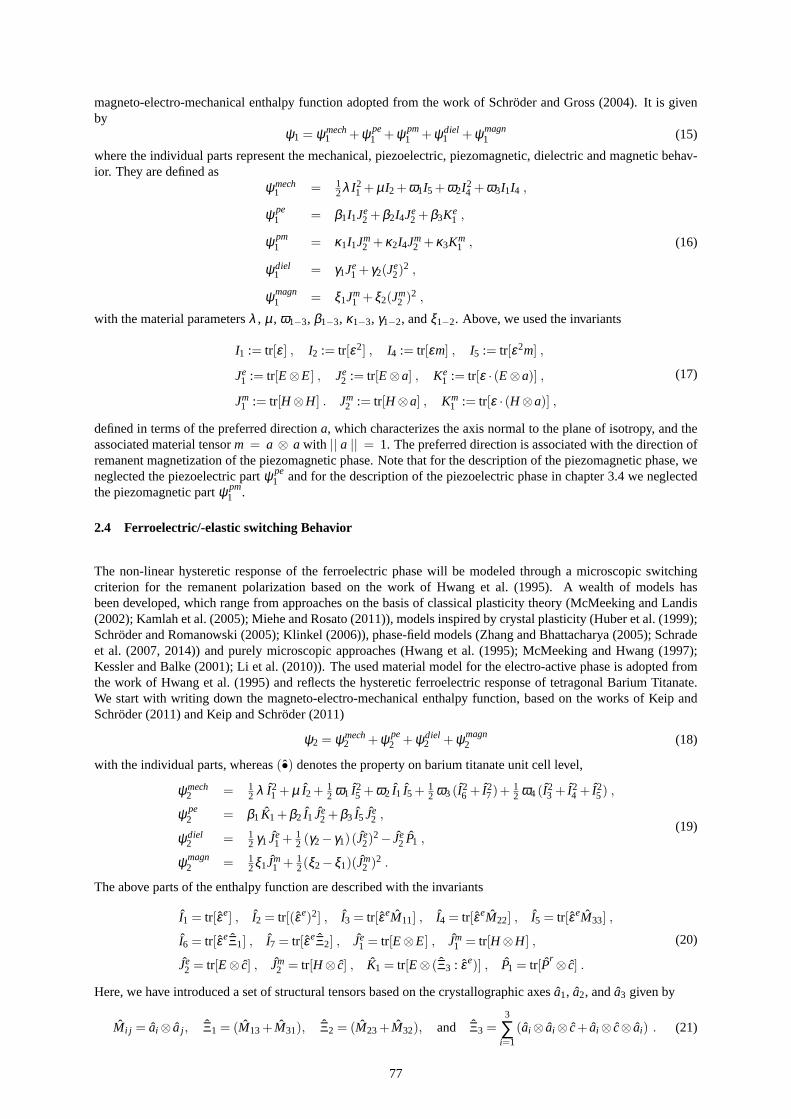
Figure 5: a) Butterfly hysteresis and b) dielectric hysteresis curves over an electric fieldE3 for different appliedcompressive stresses.
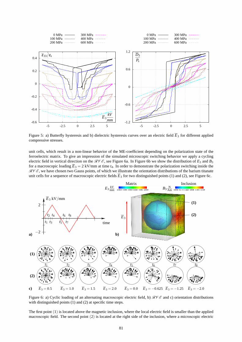
unit cells, which result in a non-linear behavior of the ME-coefficient depending on the polarization state of theferroelectric matrix. To give an impression of the simulated microscopic switching behavior we apply a cyclingelectric field in vertical direction on theRV E , see Figure 6a. In Figure 6b we show the distribution ofE3 andB3
for a macroscopic loadingE3 = 2 kV/mm at timet4. In order to demonstrate the polarization switching insidetheRV E , we have chosen two Gauss points, of which we illustrate the orientation distributions of the barium titanateunit cells for a sequence of macroscopic electric fieldsE3 for two distinguished points (1) and (2), see Figure 6c.
a) b)
c)
Matrix InclusionE3
kVmm B3
NAm
E3 kV/mm
2
−2
time
E3t1
t2
t3
t4
t5
t6
t7
t8
(1)
(2)
(1)
(2)
t1 t2 t3 t4 t5 t6 t7 t8
E3 = 0.5 E3 = 1.0 E3 = 1.5 E3 = 2.0 E3 = 0.0 E3 =−0.625 E3 =−1.25 E3 =−2.0
Figure 6: a) Cyclic loading of an alternating macroscopic electric field, b)RV E and c) orientation distributionswith distinguished points (1) and (2) at specific time steps.
The first point(1) is located above the magnetic inclusion, where the local electric field is smaller than the appliedmacroscopic field. The second point(2) is located at the right side of the inclusion, where a microscopic electric
81

field concentration (E3) is observed in a horizontal area around the magnetic inclusion. For imaging the switchingbehavior the orientation distributions in both integration points are depicted at the eight points of timet1 to t8,which focus on the loading process of the electric field in positive and negative direction. During the first 4 timestepst1 to t4 for an increased electric field we observe a switching of the orientations which then point into thedirection of the applied field. When the electric field decreases to the maximum negative value, during the timestepst5 to t8, a stepwise reorientation of the unit cells takes place. By comparing the behavior in both points weclearly see a different switching response due to the different local electric fields.For a more precise prediction of the ME-coefficient we performed simulations with a refined finite element meshof theRV E s. Furthermore, we applied compressive stresses on the composite to investigate their influences onthe ME-coefficient. The resulting hysteresis loops and the non-linear behavior of the ME-coefficients are depictedin Figure 7.
-0.4
-0.2
0
0.2
-5 -2.5 0 2.5 5
0 MPa100 MPa150 MPa200 MPa
300 MPa400 MPa500 MPa600 MPa
-0.75
-0.375
0
0.375
0.75
-5 -2.5 0 2.5 5
0 MPa100 MPa150 MPa200 MPa
300 MPa400 MPa500 MPa600 MPa
E3 kV/mm
ε33/εs
E3 kV/mm
D3
Ps
-1.5e-10
-7.5e-11
0
7.5e-11
1.5e-10
-5 -2.5 0 2.5 5
0 MPa100 MPa150 MPa200 MPa
-1.5e-10
-7.5e-11
0
7.5e-11
1.5e-10
-5 -2.5 0 2.5 5
α33sm
α33sm
E3 kV/mm
a) b)
c) d)
Figure 7: a) Effective response of the butterfly hysteresis loops, b) dielectric hysteresis, c) ME coefficient forapplied stresses from 0 MPa to 200 MPa and d) ME coefficient forapplied stresses of 200 MPa.
We observe a strong dependency of the transferred strains from the electric matrix to the magnetic inclusionon the ME coefficient. The magnitude of the magneto-electriccoupling is based on the incremental change ofthe electric butterfly hysteresis curve. Here we observe a saturation of the ME-coefficient under high electricfields. When the electric field loading is removed, a remanent ME-coefficient remains, which is in the case of nocompressive stresses approximately half to the one predicted with purely linear piezoelectric and piezomagneticmaterial models with assumed idealized polarization and magnetization. The modified electro-mechanical be-havior in case of applied compressive stresses affects the magneto-electric coupling in a positive manner, seeFigure 7c. At a compressive stress of 200 MPa the ME-coefficient at remanent polarization is raised up toα33(σ33 = 200MPa) = 1.423 · 10−10 s/m and is 304.1 % larger than the coupling coefficient at an unstressedstate (α33(σ33 = 0 MPa) = 0.4709 · 10−11 s/m). The performed simulations of the ME coefficients are notadjusted to experimental measurements and are purely predictions of the used material models. However, the au-thors would assume a decrease of the ME coefficient for increasing applied compressive stresses. This materialbehavior is due to the complexity of the microscopic interactions an open question, which will be investigated in afuture work, where we will compare the simulated results with experimental measurements.
82

3.4 Influence of the Microscopic Morphology on ME Coefficients
As already demonstrated in Figure 6 the heterogeneous microstructure and the resulting inhomogeneous distribu-tion of the local electric fields play a significant role on thelocal polarization states. Regions inside the microstruc-ture with low electric field distributions show accordinglysmall electro-mechanical properties, which decreasesthe strain-induced magneto-electric coupling. To investigate the influence of the microscopic morphology on theME-coefficient we performed 25 simulations with composites, consisting of a piezoelectric matrix and differentellipsoidal piezomagnetic inclusions with varying volumefractions. Here, we restricted the simulations to two-dimensional boundary value problems and purely transversely isotropic linear material models. The used materialparameters for polycrystalline barium titanate and cobaltferrite are listed in Table 4. Here it has to be emphasized,that we consider non-conductive magnetic inclusion. In allsimulations a macroscopic electric field of 2 kV/mm invertical direction is applied and periodic boundary conditions are used on theRV E .
Table 4: Material parameters for polycrystal barium titanate and cobalt ferrite, see Bechmann (1956); Stevens et al.(1956); Murthy (1983); Lee et al. (2005); Labusch et al. (2014); Schroder et al. (2015a).
Modulus Unit BaTiO3 CoFe2O4 Modulus Unit BaTiO3 CoFe2O4
C11N
mm2 16.6·104 21.21·104ǫ11 (ǫ
r11)
mCkVm 112·10−4 (1265) 0.80·10−4 (9)
C12N
mm2 7.7·104 7.45·104ǫ33 (ǫ
r33)
mCkVm 126·10−4 (1423) 0.93·10−4 (11)
C13N
mm2 7.8·104 7.45·104 q31N
kAmm 0.0 580.3
C33N
mm2 16.2·104 21.21·104 q33N
kAmm 0.0 −699.7
C44N
mm2 4.3·104 6.88·104 q15N
kAmm 0.0 550.0
e31Cm2 −4.4 0.0 µ11 (µ r
11)N
kA2 1.26 (1.003) 157.0 (124.9)
e33Cm2 18.6 0.0 µ33 (µ r
33)N
kA2 1.26 (1.003) 157.0 (124.9)
e15Cm2 11.6 0.0
Figure 8 shows three example microstructures with different inclusion geometries but equal volume fractions. Thelongitudinal expansions of the ellipsoids with varying volume fractions is kept constant to enable a comparisonwith the different microstructures. Figure 8 also depicts the electric field distributionE2 of the composites.
a)
kVmm
α22 = 1.1465·10−10 s/m b)
kVmm
α22 = 1.6517·10−10 s/m c)
kVmm
α22 = 2.1963·10−10 s/m
Figure 8: Electric field distributionE2 for three example microstructures with 30 % inclusion volume fraction.
We can clearly observe, that due to the different electric permittivity of the magnetic inclusion concentrations ofthe electric fields occur at the left and right boundary of theinclusions. Simultaneously, very low microscopicelectric fields, in comparison with the applied macroscopicfield, are present at the vertical boundaries. For ahigh magneto-electric coupling the electro-mechanical properties of the matrix in the regions of the interphasebetween both constituents should also be enhanced, which isthe case for ellipsoidal inclusions aligned along thedirection of the applied electric field. As a consequence theME-coefficient for the three composites raised fromα22 = 1.1465·10−10 s/m for a) overα22 = 1.6517·10−10 s/m for b) to α22 = 2.1963·10−10 s/m for c).
83

Rx
Ry
x
y
Ry/Rxrel. vol. incl.
α22sm α22
sm
αmax22 = 3.3739·10−10 s
m
Figure 9: Three-dimensional visualization of the ME-coefficients for different inclusion geometries and volumefractions.
A visualization of the ME-coefficients of all considered microstructures is given in Figure 9. The resulting ME-coefficients are plotted against the inclusion volume fraction and the ratio between the horizontal and verticalradius of the ellipsoidal inclusion, which yield a three-dimensional plot, where the highest point of the surfacedescribes the maximum ME-coefficient. Taking a closer look at Figure 9 we observe, that for a circular inclusionthe best ME value is obtained for 50 % volume fraction of both phases. As demonstrated in Figure 8 the MEcoupling can be increased by changing the inclusion shape toellipsoid aligned along the direction of the appliedfield. Thus, the highest ME-coefficientα22 = 3.3739·10−10 s/m is obtained for a microstructure with a verticalellipsoidal inclusion with 40 % volume fraction.
4 Conclusion
In this contribution, we proposed a two-scale homogenization approach for magneto-electro-mechanically coupledboundary value problems. The procedure was implemented into the FE2-method, which allows for the considera-tion of attached microscopic representative volume elements to compute the macroscopic boundary value problem.The main focus is on the determination of the magneto-electric coefficient and consideration of the influences ofapplied stresses and microscopic morphologies on the ME coupling. Numerical simulations demonstrate the en-hancement of the ME-coefficient under compressive stressesand for specific shapes of the magnetic inclusions.To further improve the prediction of the effective properties, we inspected a ferroelectric pre-polarization pro-cess by considering the microscopic ferroelectroelastic switching behavior. In this contribution we have neglectedany conductivity of the magnetic inclusion considering only the net (= high frequency) dielectric constant. Themore realistic case of low but finite conductivity is plannedfor future work. In future developments we will moreprecisely simulate the magnetostrictive response by implementing a non-linear dissipative material model.
Acknowledgement
We gratefully acknowledge the financial support of the German Research Foundation (DFG) in the framework ofthe research unit 1509 “Ferroic Functional Materials – Multiscale Modeling and Experimental Characterization”,project 1 SCHR 570/12-1, project 2 (LU 729/12) and project 3 (KE 1849/2-2).
84

References
Arockiarajan, A.; Sivakumar, S.; Sansour, C.: A thermodynamically motivated model for ferroelectric ceramicswith grain boundary effects.Smart Materials and Structures, 19(1), (2010), 015008.
Astrov, D.: Magnetoelectric effect in chromium oxide.Journal of Experimental and Theoretical Physics, 40,(1961), 1035–1041.
Avakian, A.; Gellmann, R.; Ricoeur, A.: Nonlinear modelingand finite element simulation of magnetoelectriccoupling and residual stress in multiferroic composites.Acta Mechanica, 226, (2015), 2789–2806.
Bechmann, R.: Elastic, piezoelectric, and dielectric constants of polarized barium titanate ceramics and someapplications of the piezoelectric equations.The Journal of the Acoustical Society of America, 28, (1956), 347–350.
Bibes, M.; Barthelemy, A.: Multiferroics: Towards a magnetoelectric memory.Nature Materials, 7, 6, (2008),425–426.
Crottaz, O.; Rivera, J.-P.; Revaz, B.; Schmid, H.: Magnetoelectric effect of Mn3B7O13I boracite.Ferroelectrics,204, (1997), 125–133.
Eerenstein, W.; Mathur, N. D.; Scott, J. F.: Multiferroic and magnetoelectric materials.Nature, 442, 7104, (2006),759–765.
Fiebig, M.: Revival of the magnetoelectric effect.Journal of Physics D: Applied Physics, 38, (2005), R123–R152.
Fuller, R.: Geodesic Structures (August 1965).
Geers, M. G. D.; Kouznetsova, V. G.; Brekelmans, W. A. M.: Multi-scale computational homogenization: Trendsand challenges.Journal of Computational and Applied Mathematics, 234, 7, (2010), 2175–2182, fourth Inter-national Conference on Advanced Computational Methods in Engineering (ACOMEN 2008).
Hill, N.: Why are there so few magnetic ferroelectrics?The Journal of Physical Chemistry B, 104, (2000), 6694–6709.
Hill, R.: Elastic properties of reinforced solids – some theoretical principles.Journal of the Mechanics and Physicsof Solids, 11, (1963), 357–372.
Huber, J.; Fleck, N.; Landis, C.; McMeeking, R.: A constitutive model for ferroelectric polycrystals.Journal ofthe Mechanics and Physics of Solids, 47, (1999), 1663–1697.
Hwang, S.; Lynch, C.; McMeeking, R.: Ferroelectric/ferroelastic interaction and a polarization switching model.Acta metall. mater., 43, (1995), 2073–2084.
Kamlah, M.: Ferroelectric and ferroelastic piezoceramics- modeling of electromechanical hysteresis phenomena.Continuum Mechanics and Thermodynamics, 13, (2001), 219–268.
Kamlah, M.; Liskowsky, A.; McMeeking, R.; Balke, H.: Finiteelement simulation of a polycrystalline ferroelectricbased on a multidomain single crystal switching model.International Journal of Solids and Structures, 42,(2005), 2949–2964.
Keip, M.-A.: Modeling of Electro-Mechanically Coupled Materials on Multiple Scales. Ph.D. thesis, University ofDuisburg-Essen (2012).
Keip, M.-A.; Schroder, J.: A ferroelectric and ferroelastic microscopic switching criterion for tetragonal ferro-electrics.Proceedings in Applied Mathematics and Mechanics, 11, 1, (2011), 475–476.
Keip, M.-A.; Schroder, J.: On the modeling of microscopic switching phenomena in tetragonal ferroelectric ma-terials. In:Proceedings of the 19th International Conference on Computer Methods in Mechanics, CMM 2011,Warschau, Polen (Mai, 9-12 2011).
Keip, M.-A.; Steinmann, P.; Schroder, J.: Two-scale computational homogenization of electro-elasticity at finitestrains.Computer Methods in Applied Mechanics and Engineering, 278, (2014), 62–79.
Kessler, H.; Balke, H.: On the local and average energy release in polarization switching phenomena.Journal ofthe Mechanics and Physics of Solids, 49, (2001), 953–978.
85
Klinkel, S.: A phenomenological constitutive model for ferroelastic and ferroelectric hysteresis effects in ferro-electric ceramics.International Journal of Solids and Structures, 43, (2006), 7197–7222.
Labusch, M.; Etier, M.; Lupascu, D.; Schroder, J.; Keip, M.-A.: Product properties of a two-phase magneto-electriccomposite: Synthesis and numerical modeling.Computational Mechanics, 54, (2014), 71–83.
Lee, J. S.; Boyd, J. G.; Lagoudas, D. C.: Effective properties of three-phase electro-magneto-elastic composites.International Journal Of Engineering Science, 43, 10, (2005), 790–825.
Li, Q.; Ricoeur, A.; Enderlein, M.; Kuna, M.: Evaluation of electromechanical coupling effect by microstructuralmodeling of domain switching in ferroelectrics.Mechanics Research Communications, 37, (2010), 332–336.
Mandel, J.; Dantu, P.: Conributiona l’etude theorique et experimentale du coefficient d’elasticite d’un milieuheterogene mais statistiquement homogene.Annales des Ponts et Chaussees.
McMeeking, R.; Hwang, S.: On the potential energy of a piezoelectric inclusion and the criterion for ferroelectricswitching.Ferroelectrics, 200, (1997), 151–173.
McMeeking, R.; Landis, C.: A phenomenological multi-axialconstitutive law for switching in polycrystallineferroelectric ceramics.International Journal of Engineering Science, 40, (2002), 1553–1577.
Miehe, C.; Bayreuther, C.: On mutiscale FE analyses of heterogeneous structures: from homogenization to multi-grid solvers.International Journal For Numerical Methods In Engineering, 71, (2007), 1135–1180.
Miehe, C.; Koch, A.: Computational micro-to-macro transitions of discretized microstructures undergoing smallstrains.Archive of Applied Mechanics, 72, 4, (2002), 300–317.
Miehe, C.; Rosato, D.: A rate-dependent incremental variational formulation of ferroelectricity.InternationalJournal of Engineering Science, 49, (2011), 466–496.
Miehe, C.; Rosato, D.; Kiefer, B.: Variational principles in dissipative electro-magneto-mechanics: A frameworkfor the macro-modeling of functional materials.International Journal for Numerical Methods in Engineering,86, 10, (2011), 1225–1276.
Murthy, S.: Delta-e effect in co-zn ferrites.Physica Status Solidi A-Applied Research, 80, (1983), K161–K165.
Nan, C.-W.: Magnetoelectric effect in composites of piezoelectric and piezomagnetic phases.Phys. Rev. B, 50,(1994), 6082–6088.
Rivera, J.-P.: On definitions, units, measurements, tensorforms of the linear magnetoelectric effect and on a newdynamic method applied to cr-cl boracite.Ferroelectrics, 161, (1994), 165–180.
Rivera, J.-P.; Schmid, H.: On the birefringence of magnetoelectric bifeo3. Ferroelectrics, 204, (1997), 23–33.
Schrade, D.; Mueller, R.; Xu, B.; Gross, D.: Domain evolution in ferroelectric materials: A continuum phasefield model and finite element implementation.Computer methods in applied mechanics and engineering, 196,(2007), 4365–4374.
Schrade, D.; Muller, R.; Gross, D.; Keip, M.-A.; Thai, H.; Schroder, J.: An invariant formulation for phase fieldmodels in ferroelectrics.International Journal of Solids and Structures, 51, 11, (2014), 2144–2156.
Schroder, J.: Derivation of the localization and homogenization conditions for electro-mechanically coupled prob-lems.Computational Materials Science, 46, 3, (2009), 595–599.
Schroder, J.; Gross, D.: Invariant formulation of the electromechanical enthalpy function of transversely isotropicpiezoelectric materials.Archive of Applied Mechanics, 73, (2004), 533–552.
Schroder, J.; Keip, M.-A.: Two-scale homogenization of electromechanically coupled boundary value problems.Computational Mechanics, 50, (2012), 229–244.
Schroder, J.; Labusch, M.; Keip, M.-A.: Algorithmic two-scale transition for magneto-electro-mechanically cou-pled problems - fe2-scheme: Localization and homogenization.Computer Methods in Applied Mechanics andEngineering, (submitted), . in preparation.
Schroder, J.; Labusch, M.; Keip, M.-A.; Kiefer, B.; Brands, D.; Lupascu, D.: Computation of non-linear magneto-electric product properties of 0-3 composites.GAMM-Mitteilungen, 38(1), (2015b), 1–8.
86

Schroder, J.; Romanowski, H.: A thermodynamically consistent mesoscopic model for transversely isotropic fer-roelectric ceramics in a coordinate-invariant setting.Archive of Applied Mechanics, 74, 11-12, (2005), 863–877.
Spaldin, N.; Fiebig, M.: The Renaissance of Magnetoelectric Multiferroics.Science, 309, (2005), 391–392.
Stevens, D.; Schweinler, H.; Sturm, W.; Sonder, E.: The magnetic susceptibility of barium titanate.Solid StateDivision Semiannual Progress Report, 30, (1956), 13–14.
Vaz, C.; Hoffman, J.; Ahn, C.; Ramesh, R.: Magnetoelectric coupling effects in multiferroic complex oxidecomposite structures.Advanced Materials, 22, (2010), 2900–2918.
Yen, J.; Shu, Y.; Shieh, J.; Yeh, J.: A study of electromechanical switching in ferroelectric single crystals.Journalof the Mechanics and Physics of Solids, 56, (2008), 2117–2135.
Zah, D.; Miehe, C.: Computational homogenization in dissipative electro-mechanics of functional materials.Com-puter Methods in Applied Mechanics and Engineering, 267, (2013), 487–510.
Zgonik, M.; Bernasconi, P.; Duelli, M.; Schlesser, R.; Gunter, P.: Dielectric, elastic, piezoelectric, electro-optic,and elasto-optic tensors of BaTiO3 crystals.Physical Review B, 50(9), (1994), 5941–5949.
Zhang, W.; Bhattacharya, K.: A computational model of ferroelectric domains. Part I: model formulation anddomain switching.Acta Materialia, 53, 1, (2005), 185–198.
Zhou, D.; Kamlah, M.; Munz, D.: Effects of uniaxial prestress on the ferroelectric hysteretic response of soft pzt.Journal of the European Ceramic Society, 25, (2005), 425–432.
Address: M.Sc. Matthias Labusch, Fakultat fur Ingenieurwissenschaften, Institut fur Mechanik, AbteilungBauwissenschaften, Universitatsstraße 15, 45141 Essenemail: [email protected]
87