On the Influence of Masonry Infills in Concrete Buildings
12
1 Abstract The new seismic code in Europe, Eurocode 8, clearly defines the structural designer as responsible for the safety of masonry infills. With the goal of contributing to the creation of simple design rules for these infills, a shaking table test program of reinforced concrete frame buildings with infill walls, reinforced and unreinforced, will be carried out. Before these tests, different numerical simulations of the buildings were done, using civil engineering finite element software, SAP2000, and a general purpose software, DIANA. The obtained results were here compared. Keywords: infill, concrete frame, reinforcement, shaking table, pushover, diagonal truss. 1 Introduction The stresses induced in a structure by a seismic action have a low probability of occurrence and their magnitude is such that the structure is forced beyond the ultimate limit state. Therefore, the first objective of seismic design is the collapse prevention of the complete structure or just part of it, so that casualties and injuries can be minimized. Damage limitation is the secondary goal, so that the rehabilitation of the structure is economically feasible. Few areas in the world can be considered as seismic action free and, even in the ones where seismicity is low to the point that no specific design rules are taken into account, the risks are clear, especially when the construction material is masonry. The effective standards in Portugal, and the ones that will be effective shortly, consider the possibility of a seismic action in all the territory, fact that has been neglect by designers and authorities in the last years. This new standard, Eurocode 8, Design of structures for earthquake resistance, defines new standards for infill walls, Paper 102 On the Influence of Masonry Infills in Concrete Buildings J. Leite and P.B. Lourenço ISISE University of Minho, Portugal ©Civil-Comp Press, 2010 Proceedings of the Tenth International Conference on Computational Structures Technology, B.H.V. Topping, J.M. Adam, F.J. Pallarés, R. Bru and M.L. Romero, (Editors), Civil-Comp Press, Stirlingshire, Scotland
description
INFILLED RC FRAME
Transcript of On the Influence of Masonry Infills in Concrete Buildings

1
Abstract The new seismic code in Europe, Eurocode 8, clearly defines the structural designer as responsible for the safety of masonry infills. With the goal of contributing to the creation of simple design rules for these infills, a shaking table test program of reinforced concrete frame buildings with infill walls, reinforced and unreinforced, will be carried out. Before these tests, different numerical simulations of the buildings were done, using civil engineering finite element software, SAP2000, and a general purpose software, DIANA. The obtained results were here compared. Keywords: infill, concrete frame, reinforcement, shaking table, pushover, diagonal truss.
1 Introduction The stresses induced in a structure by a seismic action have a low probability of occurrence and their magnitude is such that the structure is forced beyond the ultimate limit state. Therefore, the first objective of seismic design is the collapse prevention of the complete structure or just part of it, so that casualties and injuries can be minimized. Damage limitation is the secondary goal, so that the rehabilitation of the structure is economically feasible. Few areas in the world can be considered as seismic action free and, even in the ones where seismicity is low to the point that no specific design rules are taken into account, the risks are clear, especially when the construction material is masonry. The effective standards in Portugal, and the ones that will be effective shortly, consider the possibility of a seismic action in all the territory, fact that has been neglect by designers and authorities in the last years. This new standard, Eurocode 8, Design of structures for earthquake resistance, defines new standards for infill walls,
Paper 102 On the Influence of Masonry Infills in Concrete Buildings J. Leite and P.B. Lourenço ISISE University of Minho, Portugal
©Civil-Comp Press, 2010 Proceedings of the Tenth International Conference on Computational Structures Technology, B.H.V. Topping, J.M. Adam, F.J. Pallarés, R. Bru and M.L. Romero, (Editors), Civil-Comp Press, Stirlingshire, Scotland
2
imposing the use of reinforcement but failing to give detailed information besides the type of reinforcement. Furthermore, the structural designer is the responsible for these non-structural elements. Taking into account the role of the infill walls in a building, the fact that it is the most used enclosure system in Europe, the relevance in the seismic behaviour and also the costs associated to the post-earthquake rehabilitation, the importance of the present work is clear. Therefore, with the goal of contributing to the creation of simple design rules for these infills, a shaking table test program of reinforced concrete frame buildings with infill walls, reinforced and unreinforced, will be carried out. Predeceasing these tests, different numerical simulations of the buildings were done.
2 Geometry and vertical loads The present work analyses the infill walls of framed concrete structures, as this is the most common structural system in Portugal. Three different models, sharing the same geometry, Figure 1, were idealized for an experimental program in the shaking table of the National Laboratory of Civil Engineering (LNEC), in Lisbon.
Side View A Side View B
B
A5,7
33
3,23 3,23
Top View
6,45
Figure 1: Geometry of the buildings, in meters.
Taking into account the limitations of the referred shaking table, the models were reduced to a scale of 1:1.5, using Cauchy’s Similarity Law. This Law relates all the key properties of the prototype (1:1) and the model (1:1.5) by a parameter, l, which in this case assumes the value of 1.5, Figure 2.

3
Parameter Scale Factor Parameter Scale Factor
Length (L) Mass (m)
Elasticity Module ( E )
Weight (w)
Specific Mass (ρ) Force (F)
Area (A) Flexural Moment (M)
Volume (V)
Stress (τ)
Displacements (d) Strain (ε)
Velocity (v) Time (t)
Acceleration (a)
Frequency (f)
Figure 2: Relation between Prototype and Model of the need parameters for the
design of the structure following Cauchy’s Law. The models are obtained by varying both the standard, from which the design of the reinforced concrete structure is done, and the enclosure system. The first model tries to replicate the buildings constructed in the last two decades, Figure 3 (a), and was designed following the effective standard, Standard for Reinforced and Pre-Stressed Concrete Structures (REBAP) [1]. The other represent two enclose systems, Figure 3 (b) and (c), that could be future constructive solutions, both reinforced, and the design was done with regard to the Eurocodes 1, 2 and 8 [2][3][4].
(a) (b)
(c)
Figure 3: Enclosure systems of the models: (a) unreinforced double leaf wall;
(b) bed joint reinforced single leaf wall; (c) single leaf with light wire anchored to the concrete frame.
1=m
P
EE
1=m
P
ρρ
2λ=m
P
AA
3λ=m
P
VV
λ=m
P
dd
1=m
P
vv
1−= λm
P
aa
3λ=m
P
mm
3λ=m
P
ww
2λ=m
P
FF
3λ=m
P
MM
1=m
P
ττ
1=m
P
εε
λ=m
P
tt
1−= λm
P
ff
λ=m
P
LL

4
3 Analyses Several numerical simulations were carried out, with two main objectives: i) understand the behavior of the structure when subjected to a seismic action, in order to more accurately define the experimental program; ii) using different computational programs and numerical elements to perform static non-linear analyses, assess the capability of a commercial Finite Element Method (FEM) software, SAP2000, to simulate infill walls by means of a diagonal strut, comparing it to a more generic and powerful tool, DIANA. The non-linear static analyses were done in three sets, each one with two types of analyses, Figure 4.
SET 1: SAP2000 with bar elements; masonry infills simulated as diagonal struts
With infills Without infills
SET 2: DIANA with bar elements; masonry infills simulated as diagonal struts
With infills Without infills
SET 3: DIANA with FEM mesh; masonry infill simulated as FEM mesh
With infills Without infills
Figure 4: Sets of analysis done and the parametric study within each one.
As far as the horizontal loads for the non-linear are concerned, the Eurocode 8 was followed, therefore two load parameters were created: one proportional to the mass and independent of the elevation, referred to as Uniform; another one which takes elevation into consideration, named Modal, automatically computed in the SAP2000 analyses by the software.
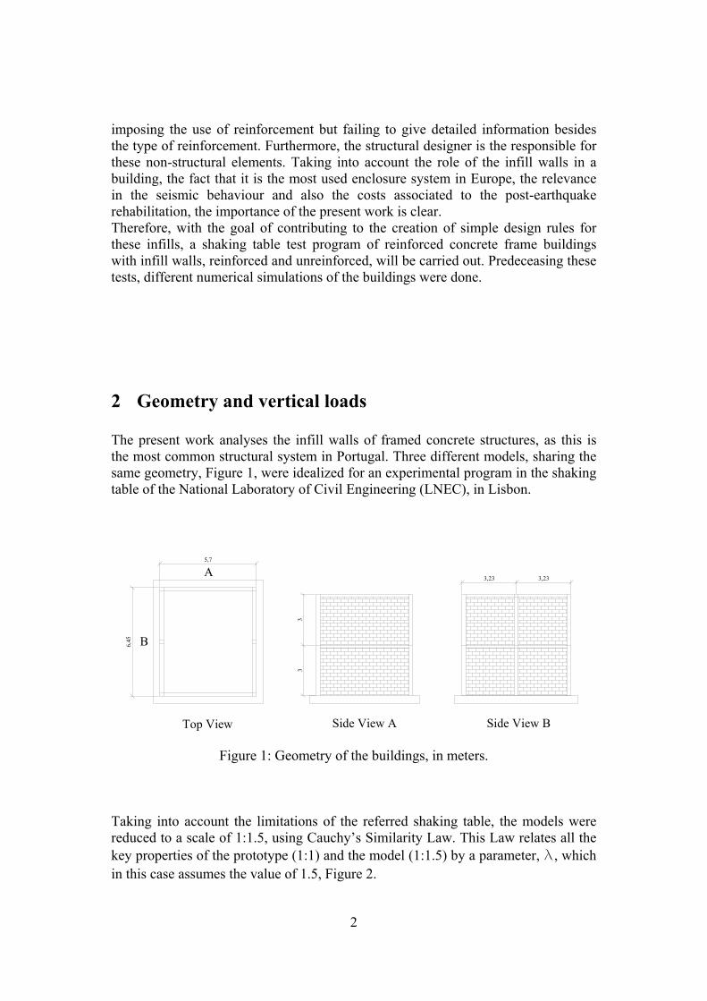
3.1 Analyses with SAP2000 Bar elements are referred to, in SAP2000, as frame elements. These very powerful elements can be used to model, i.e., beams and columns in planar and three-dimensional structures and its formulation include the effect of the biaxial bending, torsion, axial deformation and biaxial shear deformations [5]. To include material non-linear behavior, frame hinges need to be defined and assigned. The definition includes the type of hinge, which defines the type of force that activates the hinge, and the relation between those forces. The M2 hinges (activated by flexural moments in the second direction) were assigned to both the extremities of the concrete beam elements, and PMM (axial and bi-flexure activated) ones assigned to both extremities of the concrete column elements. The relation between the forces, for both hinges, was automatically generated by SAP2000, based on the formulations prescribed by FEMA356 [6] and, obviously, on the section properties. For the diagonal struts, hinges activated by axial force were assigned also to the extremities of the element, and the relation was user-defined, Figure 5.
5
Figure 5: Force-displacement relation for the hinges assigned to the diagonal struts
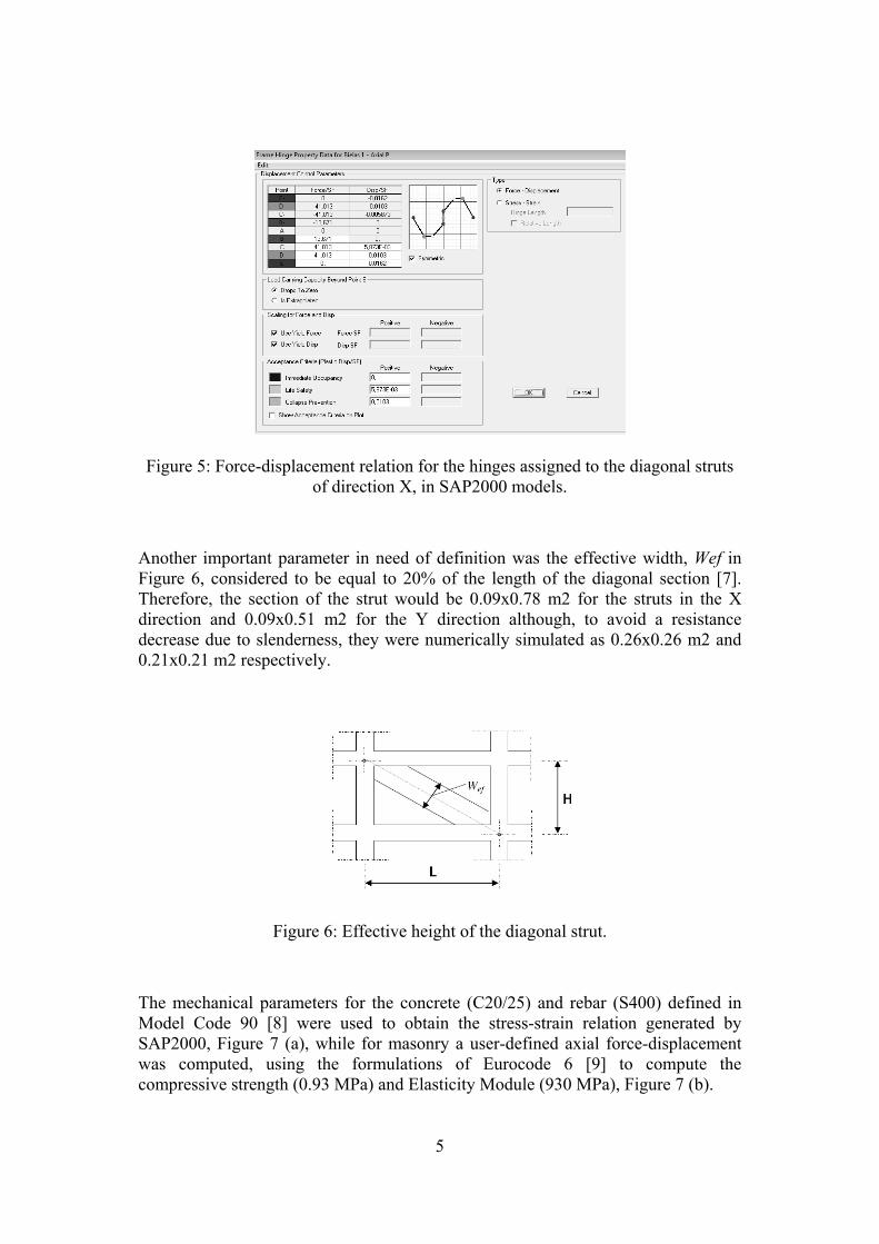
of direction X, in SAP2000 models. Another important parameter in need of definition was the effective width, Wef in Figure 6, considered to be equal to 20% of the length of the diagonal section [7]. Therefore, the section of the strut would be 0.09x0.78 m2 for the struts in the X direction and 0.09x0.51 m2 for the Y direction although, to avoid a resistance decrease due to slenderness, they were numerically simulated as 0.26x0.26 m2 and 0.21x0.21 m2 respectively.
Figure 6: Effective height of the diagonal strut. The mechanical parameters for the concrete (C20/25) and rebar (S400) defined in Model Code 90 [8] were used to obtain the stress-strain relation generated by SAP2000, Figure 7 (a), while for masonry a user-defined axial force-displacement was computed, using the formulations of Eurocode 6 [9] to compute the compressive strength (0.93 MPa) and Elasticity Module (930 MPa), Figure 7 (b).

6
(a) (b)
Figure 7: Stress – Strain relation in SAP2000: (a) concrete; (b) masonry.
3.2 Analysis with DIANA - bar elements In the numerical simulations done with this software, reinforced concrete elements were simulated with Class II beams, with several integration points along the length and depth, based on Bernoulli’s theory therefore, not taking into account shear deformation. These simulations were not three-dimensional, like the previous ones, but in a plane stress state and for that reason, two-node bi-dimensional elements, referred to as L7BEN by the software, were assigned to the beam elements, Figure 8.
Figure 8: L7BEN beam element. A constitutive model based on total strain, referred to as Total Strain Crack Model, was defined for concrete and masonry. This type of model defines the behavior of the material, in tension and compression, with a stress-strain relation. It was also defined that this stress-strain relation should be evaluated in a fixed coordinate system, adding the Fixed adjective to the name of the model: Total Strain Fixed Crack Model. [10]. The Von Mises yield criterion was used for the rebar. The mechanical parameters needed to completely compute these constitutive laws were obtained from MC90, concrete and rebar, and [11], masonry, Figure 9 and Figure 10. The geometry of the cross-section of the diagonal struts is the same of the models with SAP2000.
7
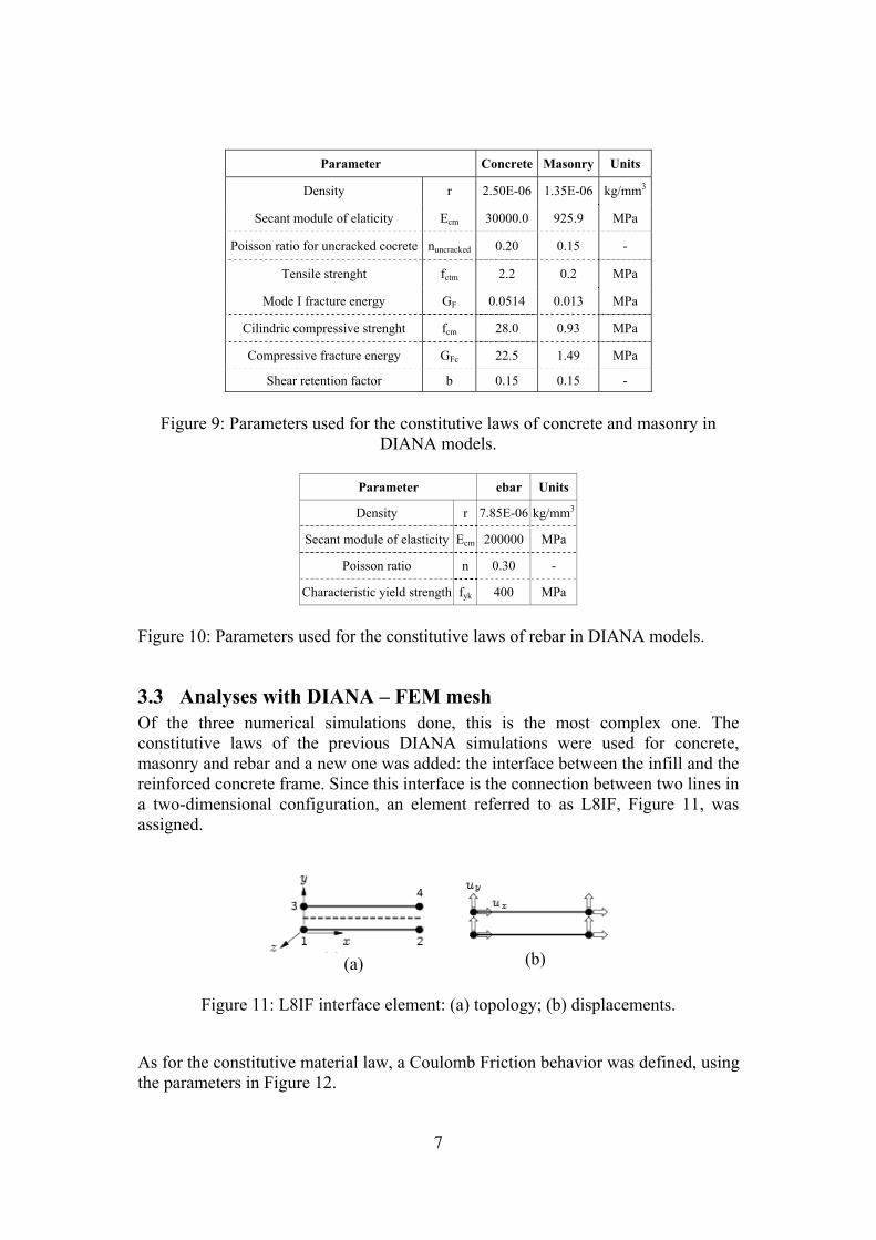
Parameter Concrete Masonry Units
Density r 2.50E-06 1.35E-06 kg/mm3
Secant module of elaticity Ecm 30000.0 925.9 MPa
Poisson ratio for uncracked cocrete nuncracked 0.20 0.15 -
Tensile strenght fctm 2.2 0.2 MPa
Mode I fracture energy GF 0.0514 0.013 MPa
Cilindric compressive strenght fcm 28.0 0.93 MPa
Compressive fracture energy GFc 22.5 1.49 MPa
Shear retention factor b 0.15 0.15 -
Figure 9: Parameters used for the constitutive laws of concrete and masonry in
DIANA models.
Parameter �ebar Units
Density r 7.85E-06 kg/mm3
Secant module of elasticity Ecm 200000 MPa
Poisson ratio n 0.30 -
Characteristic yield strength fyk 400 MPa
Figure 10: Parameters used for the constitutive laws of rebar in DIANA models.
3.3 Analyses with DIANA – FEM mesh Of the three numerical simulations done, this is the most complex one. The constitutive laws of the previous DIANA simulations were used for concrete, masonry and rebar and a new one was added: the interface between the infill and the reinforced concrete frame. Since this interface is the connection between two lines in a two-dimensional configuration, an element referred to as L8IF, Figure 11, was assigned.
(a)
(b)
Figure 11: L8IF interface element: (a) topology; (b) displacements. As for the constitutive material law, a Coulomb Friction behavior was defined, using the parameters in Figure 12.

8
Parameter Interface Units Normal traction tn 92.6 N/mm3 Shear traction tt 54.47 N/mm3
Cohesion c 0.1 - Tangent Frictiom angle tan∅ 0.5 - Tangent Dilatancy angle tanψ 0.0001 -
Tensile Strength ft 0.05 MPa Constant Shear Retention - 0.15 -
Figure 12: Parameters used for the constitutive law of the interface between masonry
and concrete frame in DIANA models. For the concrete and masonry, Q8MEM elements were used. These are four-node isoparametric plane-stress elements, based on linear interpolation and Gauss integration, Figure 13.
Figure 13 : Q8MEM element.
4 Results
4.1 Capacity curves
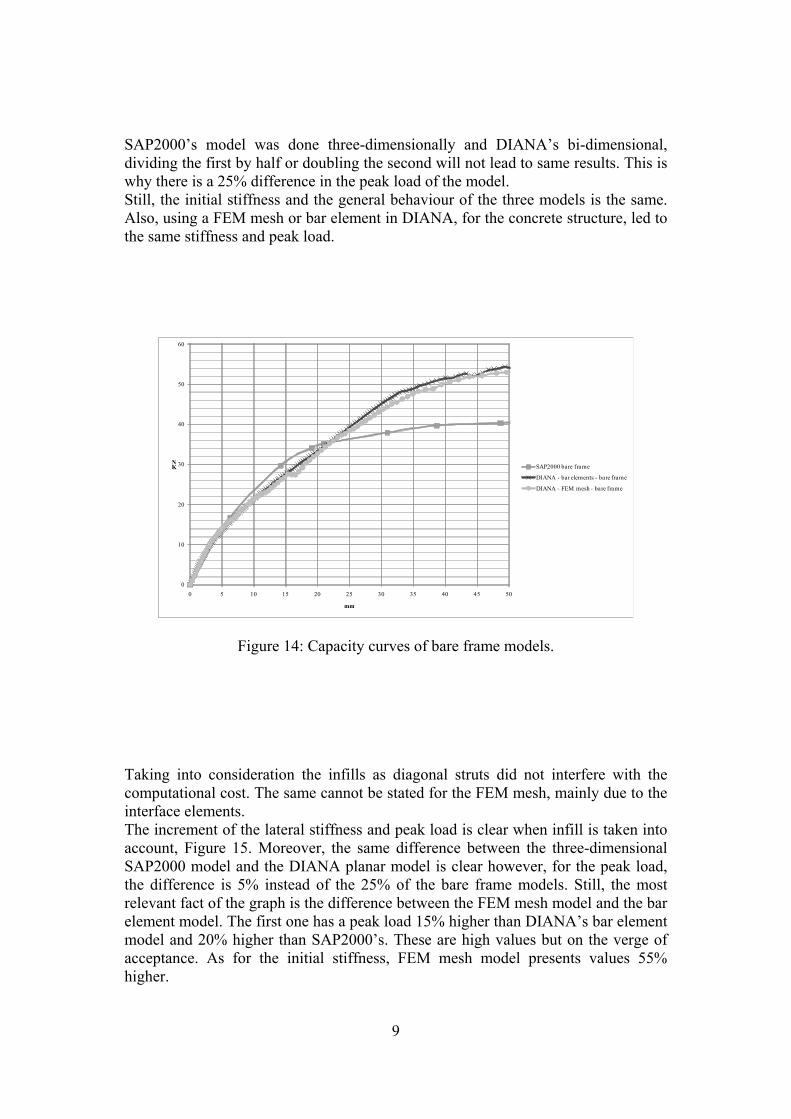
The results presented in this section, refer to the X direction, in the SAP2000 models, and the type A frame, in the DIANA ones. It was also referred above that two load cases were used although, taking into consideration the simplicity of the structure and the small height, there were no practical differences between them, hence only the results with the Uniform pattern are presented. The capacity curve is a relation between the basal force, at the base of the structure, and the horizontal displacement, at the top of the structure, and is the typical output of non-linear static analyses. The first graph, Figure 14, presents the capacity curves of the three types of models with bare frames. It would be expectable, in such a simple model, for the curves to be coincident, or close enough for the results to be considered the same however, the capacity curve of SAP2000 does not follow the other two. The reason for this is related to the structural system that, for the direction in study, has two frames but three sets of columns, with the middle ones not connected by beams. This leads to a structural behaviour that neither fits a three frame system nor a two frame one, because the middle columns absorb a small part of the horizontal loads. Since
9
SAP2000’s model was done three-dimensionally and DIANA’s bi-dimensional, dividing the first by half or doubling the second will not lead to same results. This is why there is a 25% difference in the peak load of the model. Still, the initial stiffness and the general behaviour of the three models is the same. Also, using a FEM mesh or bar element in DIANA, for the concrete structure, led to the same stiffness and peak load.
0
10
20
30
40
50
60
0 5 10 15 20 25 30 35 40 45 50
KN
mm
SAP2000 bare frame
DIANA - bar elements - bare frame
DIANA - FEM mesh - bare frame
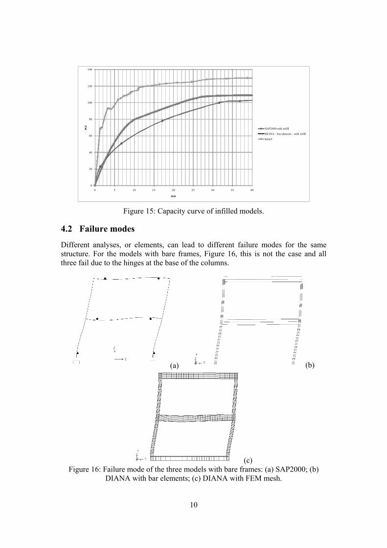
Figure 14: Capacity curves of bare frame models. Taking into consideration the infills as diagonal struts did not interfere with the computational cost. The same cannot be stated for the FEM mesh, mainly due to the interface elements. The increment of the lateral stiffness and peak load is clear when infill is taken into account, Figure 15. Moreover, the same difference between the three-dimensional SAP2000 model and the DIANA planar model is clear however, for the peak load, the difference is 5% instead of the 25% of the bare frame models. Still, the most relevant fact of the graph is the difference between the FEM mesh model and the bar element model. The first one has a peak load 15% higher than DIANA’s bar element model and 20% higher than SAP2000’s. These are high values but on the verge of acceptance. As for the initial stiffness, FEM mesh model presents values 55% higher.
10
0
20
40
60
80
100
120
140
0 5 10 15 20 25 30 35 40
KN
mm
SAP2000 with infill
DIANA - bar element - with infill
Série5
Figure 15: Capacity curve of infilled models.
4.2 Failure modes
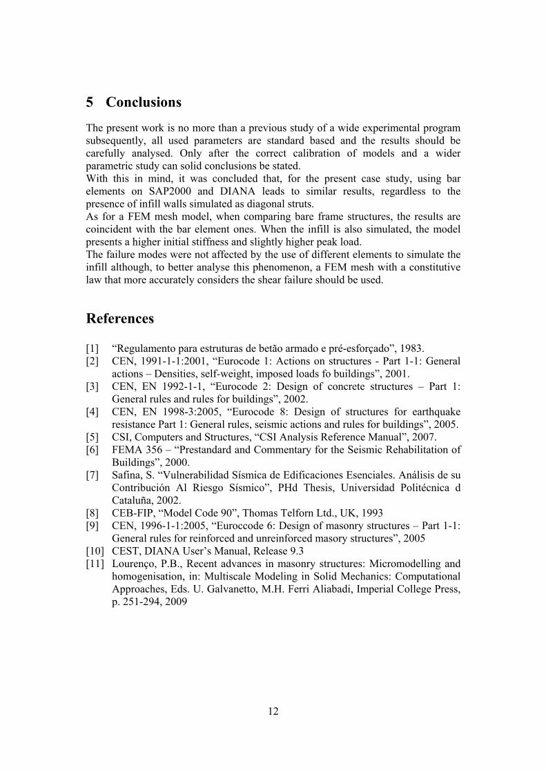
Different analyses, or elements, can lead to different failure modes for the same structure. For the models with bare frames, Figure 16, this is not the case and all three fail due to the hinges at the base of the columns.
(a) (b)
(c)Figure 16: Failure mode of the three models with bare frames: (a) SAP2000; (b)
DIANA with bar elements; (c) DIANA with FEM mesh.

11
One of the concerns of using a single diagonal strut to simulate the infill is the absence of a higher shear stress at the base of the columns due to the axial forces, since the strut is connected to the corner of the frame. This higher shear stress can lead to a premature collapse of the column. In the model with the FEM mesh this is not an issue as the effective width of the strut is connected to the frame, Figure 18. Nonetheless, and Figure 17, the failure modes were not affected, as all the models have the same failure mode.
(a) (b)
(c)
Figure 17: Failure mode of the three models with infill walls: (a) SAP2000; (b) DIANA with bar elements; (c) DIANA with FEM mesh.
Figure 18: Effective Width of the compression strut in the FEM mesh, stresses in MPa.
12
5 Conclusions The present work is no more than a previous study of a wide experimental program subsequently, all used parameters are standard based and the results should be carefully analysed. Only after the correct calibration of models and a wider parametric study can solid conclusions be stated. With this in mind, it was concluded that, for the present case study, using bar elements on SAP2000 and DIANA leads to similar results, regardless to the presence of infill walls simulated as diagonal struts. As for a FEM mesh model, when comparing bare frame structures, the results are coincident with the bar element ones. When the infill is also simulated, the model presents a higher initial stiffness and slightly higher peak load. The failure modes were not affected by the use of different elements to simulate the infill although, to better analyse this phenomenon, a FEM mesh with a constitutive law that more accurately considers the shear failure should be used.
References [1] “Regulamento para estruturas de betão armado e pré-esforçado”, 1983. [2] CEN, 1991-1-1:2001, “Eurocode 1: Actions on structures - Part 1-1: General
actions – Densities, self-weight, imposed loads fo buildings”, 2001. [3] CEN, EN 1992-1-1, “Eurocode 2: Design of concrete structures – Part 1:
General rules and rules for buildings”, 2002. [4] CEN, EN 1998-3:2005, “Eurocode 8: Design of structures for earthquake
resistance Part 1: General rules, seismic actions and rules for buildings”, 2005. [5] CSI, Computers and Structures, “CSI Analysis Reference Manual”, 2007. [6] FEMA 356 – “Prestandard and Commentary for the Seismic Rehabilitation of
Buildings”, 2000. [7] Safina, S. “Vulnerabilidad Sísmica de Edificaciones Esenciales. Análisis de su
Contribución Al Riesgo Sísmico”, PHd Thesis, Universidad Politécnica d Cataluña, 2002.
[8] CEB-FIP, “Model Code 90”, Thomas Telforn Ltd., UK, 1993 [9] CEN, 1996-1-1:2005, “Euroccode 6: Design of masonry structures – Part 1-1:
General rules for reinforced and unreinforced masory structures”, 2005 [10] CEST, DIANA User’s Manual, Release 9.3 [11] Lourenço, P.B., Recent advances in masonry structures: Micromodelling and
homogenisation, in: Multiscale Modeling in Solid Mechanics: Computational Approaches, Eds. U. Galvanetto, M.H. Ferri Aliabadi, Imperial College Press, p. 251-294, 2009