On the Effect of Tip Vortices in Low-Reynolds-Number Post-Stall ...
13
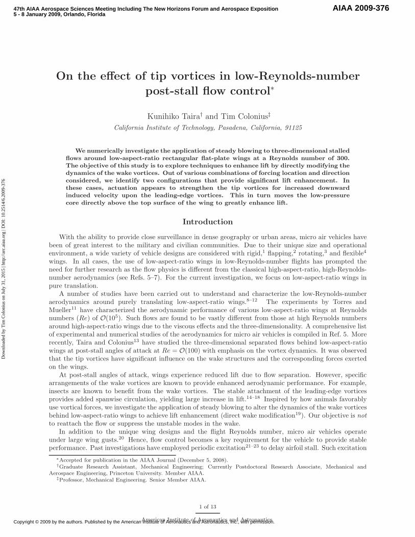
On the effect of tip vortices in low-Reynolds-number post-stall flow control ∗ Kunihiko Taira † and Tim Colonius ‡ California Institute of Technology, Pasadena, California, 91125 We numerically investigate the application of steady blowing to three-dimensional stalled flows around low-aspect-ratio rectangular flat-plate wings at a Reynolds number of 300. The objective of this study is to explore techniques to enhance lift by directly modifying the dynamics of the wake vortices. Out of various combinations of forcing location and direction considered, we identify two configurations that provide significant lift enhancement. In these cases, actuation appears to strengthen the tip vortices for increased downward induced velocity upon the leading-edge vortices. This in turn moves the low-pressure core directly above the top surface of the wing to greatly enhance lift. Introduction With the ability to provide close surveillance in dense geography or urban areas, micro air vehicles have been of great interest to the military and civilian communities. Due to their unique size and operational environment, a wide variety of vehicle designs are considered with rigid, 1 flapping, 2 rotating, 3 and flexible 4 wings. In all cases, the use of low-aspect-ratio wings in low-Reynolds-number flights has prompted the need for further research as the flow physics is different from the classical high-aspect-ratio, high-Reynolds- number aerodynamics (see Refs. 5–7). For the current investigation, we focus on low-aspect-ratio wings in pure translation. A number of studies have been carried out to understand and characterize the low-Reynolds-number aerodynamics around purely translating low-aspect-ratio wings. 8–12 The experiments by Torres and Mueller 11 have characterized the aerodynamic performance of various low-aspect-ratio wings at Reynolds numbers (Re) of O(10 5 ). Such flows are found to be vastly different from those at high Reynolds numbers around high-aspect-ratio wings due to the viscous effects and the three-dimensionality. A comprehensive list of experimental and numerical studies of the aerodynamics for micro air vehicles is compiled in Ref. 5. More recently, Taira and Colonius 13 have studied the three-dimensional separated flows behind low-aspect-ratio wings at post-stall angles of attack at Re = O(100) with emphasis on the vortex dynamics. It was observed that the tip vortices have significant influence on the wake structures and the corresponding forces exerted on the wings. At post-stall angles of attack, wings experience reduced lift due to flow separation. However, specific arrangements of the wake vortices are known to provide enhanced aerodynamic performance. For example, insects are known to benefit from the wake vortices. The stable attachment of the leading-edge vortices provides added spanwise circulation, yielding large increase in lift. 14–18 Inspired by how animals favorably use vortical forces, we investigate the application of steady blowing to alter the dynamics of the wake vortices behind low-aspect-ratio wings to achieve lift enhancement (direct wake modification 19 ). Our objective is not to reattach the flow or suppress the unstable modes in the wake. In addition to the unique wing designs and the flight Reynolds number, micro air vehicles operate under large wing gusts. 20 Hence, flow control becomes a key requirement for the vehicle to provide stable performance. Past investigations have employed periodic excitation 21–23 to delay airfoil stall. Such excitation ∗ Accepted for publication in the AIAA Journal (December 5, 2008). † Graduate Research Assistant, Mechanical Engineering; Currently Postdoctoral Research Associate, Mechanical and Aerospace Engineering, Princeton University. Member AIAA. ‡ Professor, Mechanical Engineering. Senior Member AIAA. 1 of 13 American Institute of Aeronautics and Astronautics 47th AIAA Aerospace Sciences Meeting Including The New Horizons Forum and Aerospace Exposition 5 - 8 January 2009, Orlando, Florida AIAA 2009-376 Copyright © 2009 by the authors. Published by the American Institute of Aeronautics and Astronautics, Inc., with permission. Downloaded by Tim Colonius on July 31, 2015 | http://arc.aiaa.org | DOI: 10.2514/6.2009-376
Transcript of On the Effect of Tip Vortices in Low-Reynolds-Number Post-Stall ...
On the effect of tip vortices in low-Reynolds-number
post-stall flow control∗
Kunihiko Taira† and Tim Colonius‡
California Institute of Technology, Pasadena, California, 91125
We numerically investigate the application of steady blowing to three-dimensional stalled
flows around low-aspect-ratio rectangular flat-plate wings at a Reynolds number of 300.
The objective of this study is to explore techniques to enhance lift by directly modifying the
dynamics of the wake vortices. Out of various combinations of forcing location and direction
considered, we identify two configurations that provide significant lift enhancement. In
these cases, actuation appears to strengthen the tip vortices for increased downward
induced velocity upon the leading-edge vortices. This in turn moves the low-pressure
core directly above the top surface of the wing to greatly enhance lift.
Introduction
With the ability to provide close surveillance in dense geography or urban areas, micro air vehicles havebeen of great interest to the military and civilian communities. Due to their unique size and operationalenvironment, a wide variety of vehicle designs are considered with rigid,1 flapping,2 rotating,3 and flexible4
wings. In all cases, the use of low-aspect-ratio wings in low-Reynolds-number flights has prompted theneed for further research as the flow physics is different from the classical high-aspect-ratio, high-Reynolds-number aerodynamics (see Refs. 5–7). For the current investigation, we focus on low-aspect-ratio wings inpure translation.
A number of studies have been carried out to understand and characterize the low-Reynolds-numberaerodynamics around purely translating low-aspect-ratio wings.8–12 The experiments by Torres andMueller11 have characterized the aerodynamic performance of various low-aspect-ratio wings at Reynoldsnumbers (Re) of O(105). Such flows are found to be vastly different from those at high Reynolds numbersaround high-aspect-ratio wings due to the viscous effects and the three-dimensionality. A comprehensive listof experimental and numerical studies of the aerodynamics for micro air vehicles is compiled in Ref. 5. Morerecently, Taira and Colonius13 have studied the three-dimensional separated flows behind low-aspect-ratiowings at post-stall angles of attack at Re = O(100) with emphasis on the vortex dynamics. It was observedthat the tip vortices have significant influence on the wake structures and the corresponding forces exertedon the wings.
At post-stall angles of attack, wings experience reduced lift due to flow separation. However, specificarrangements of the wake vortices are known to provide enhanced aerodynamic performance. For example,insects are known to benefit from the wake vortices. The stable attachment of the leading-edge vorticesprovides added spanwise circulation, yielding large increase in lift.14–18 Inspired by how animals favorablyuse vortical forces, we investigate the application of steady blowing to alter the dynamics of the wake vorticesbehind low-aspect-ratio wings to achieve lift enhancement (direct wake modification19). Our objective is not
to reattach the flow or suppress the unstable modes in the wake.In addition to the unique wing designs and the flight Reynolds number, micro air vehicles operate
under large wing gusts.20 Hence, flow control becomes a key requirement for the vehicle to provide stableperformance. Past investigations have employed periodic excitation21–23 to delay airfoil stall. Such excitation
∗Accepted for publication in the AIAA Journal (December 5, 2008).†Graduate Research Assistant, Mechanical Engineering; Currently Postdoctoral Research Associate, Mechanical and
Aerospace Engineering, Princeton University. Member AIAA.‡Professor, Mechanical Engineering. Senior Member AIAA.
1 of 13
American Institute of Aeronautics and Astronautics
47th AIAA Aerospace Sciences Meeting Including The New Horizons Forum and Aerospace Exposition5 - 8 January 2009, Orlando, Florida
AIAA 2009-376
Copyright © 2009 by the authors. Published by the American Institute of Aeronautics and Astronautics, Inc., with permission.
Dow
nloa
ded
by T
im C
olon
ius
on J
uly
31, 2
015
| http
://ar
c.ai
aa.o
rg |
DO
I: 1
0.25
14/6
.200
9-37
6
is introduced to trigger inherent instabilities in the flow to alter the wake in a favorable manner, i.e., toreattach the flow or delay separation.
Here we conduct an exploratory numerical study with steady blowing applied to low-Reynolds-numberflows around low-aspect-ratio wings. Steady forcing is considered here to restrict the parameter space (namelythe actuation frequency). Similar studies to the current investigation are the circulation control24, 25 thatutilizes the Coanda effect at the trailing edge. The flow at the trailing edge can be redirected to increasethe overall spanwise circulation of the wing and hence enhance lift. We emphasize that in the presentinvestigation, our aim is not to prevent separation but is to exploit wake vortices by changing the three-dimensional dynamics of the separated flow to enhance lift experienced by the low-aspect-ratio wings.
In the next section, we present the simulation methodology used to study the three-dimensional flowsaround the low-aspect-ratio rectangular flat-plate wings. Results for uncontrolled low-Reynolds-numberseparated flows are briefly presented with focus on the unsteady nature of vortex dynamics. Afterwards, theapplications of steady blowing are considered to increase the lift exerted on the plate at post-stall anglesof attack. Various actuator positions and locations are examined and two setups are identified for liftenhancement by utilizing tip effects. One of the effective control setups is further examined for a wide rangeof aspect ratios and angles of attacks and is found to increase lift in all cases.
Simulation Method
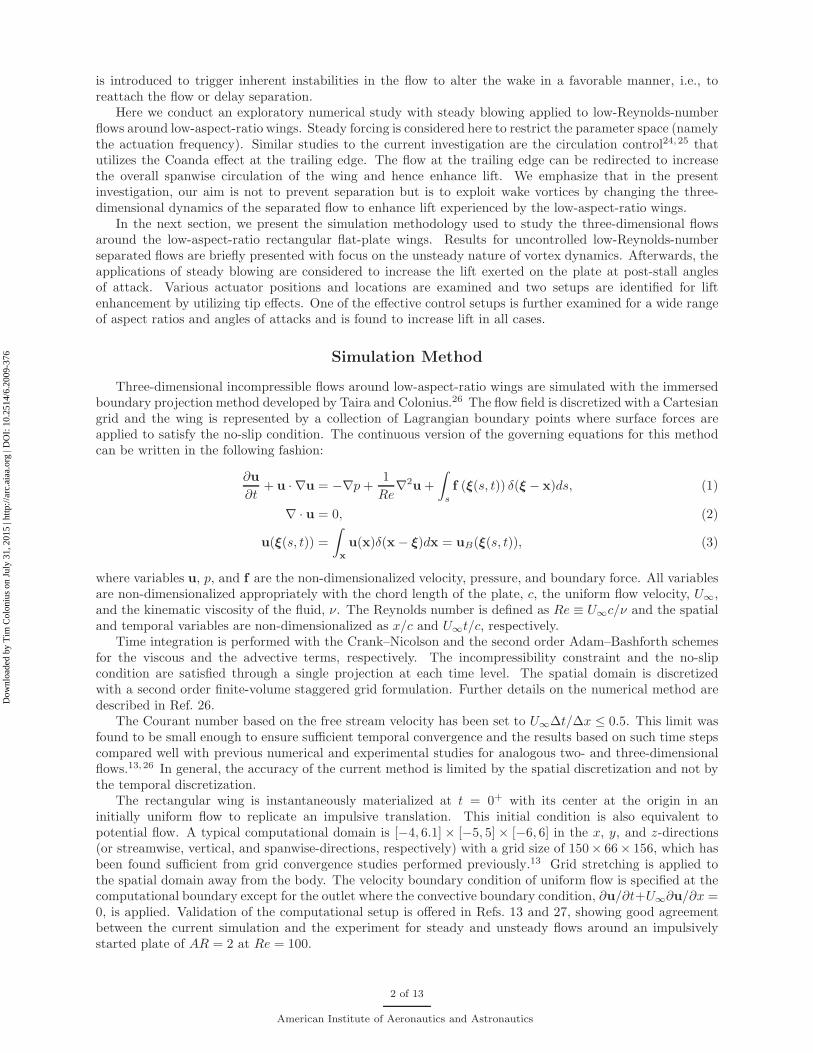
Three-dimensional incompressible flows around low-aspect-ratio wings are simulated with the immersedboundary projection method developed by Taira and Colonius.26 The flow field is discretized with a Cartesiangrid and the wing is represented by a collection of Lagrangian boundary points where surface forces areapplied to satisfy the no-slip condition. The continuous version of the governing equations for this methodcan be written in the following fashion:
∂u
∂t+ u · ∇u = −∇p +
1
Re∇2u +
∫
s
f (ξ(s, t)) δ(ξ − x)ds, (1)
∇ · u = 0, (2)
u(ξ(s, t)) =
∫
x
u(x)δ(x − ξ)dx = uB(ξ(s, t)), (3)
where variables u, p, and f are the non-dimensionalized velocity, pressure, and boundary force. All variablesare non-dimensionalized appropriately with the chord length of the plate, c, the uniform flow velocity, U∞,and the kinematic viscosity of the fluid, ν. The Reynolds number is defined as Re ≡ U∞c/ν and the spatialand temporal variables are non-dimensionalized as x/c and U∞t/c, respectively.
Time integration is performed with the Crank–Nicolson and the second order Adam–Bashforth schemesfor the viscous and the advective terms, respectively. The incompressibility constraint and the no-slipcondition are satisfied through a single projection at each time level. The spatial domain is discretizedwith a second order finite-volume staggered grid formulation. Further details on the numerical method aredescribed in Ref. 26.
The Courant number based on the free stream velocity has been set to U∞∆t/∆x ≤ 0.5. This limit wasfound to be small enough to ensure sufficient temporal convergence and the results based on such time stepscompared well with previous numerical and experimental studies for analogous two- and three-dimensionalflows.13, 26 In general, the accuracy of the current method is limited by the spatial discretization and not bythe temporal discretization.
The rectangular wing is instantaneously materialized at t = 0+ with its center at the origin in aninitially uniform flow to replicate an impulsive translation. This initial condition is also equivalent topotential flow. A typical computational domain is [−4, 6.1] × [−5, 5] × [−6, 6] in the x, y, and z-directions(or streamwise, vertical, and spanwise-directions, respectively) with a grid size of 150× 66× 156, which hasbeen found sufficient from grid convergence studies performed previously.13 Grid stretching is applied tothe spatial domain away from the body. The velocity boundary condition of uniform flow is specified at thecomputational boundary except for the outlet where the convective boundary condition, ∂u/∂t+U∞∂u/∂x =0, is applied. Validation of the computational setup is offered in Refs. 13 and 27, showing good agreementbetween the current simulation and the experiment for steady and unsteady flows around an impulsivelystarted plate of AR = 2 at Re = 100.
2 of 13
American Institute of Aeronautics and Astronautics
Dow
nloa
ded
by T
im C
olon
ius
on J
uly
31, 2
015
| http
://ar
c.ai
aa.o
rg |
DO
I: 1
0.25
14/6
.200
9-37
6
The forces on the rectangular wing of span b and chord c are reported in terms of the lift and dragcoefficients defined by:
CL =Fy
12ρU2
∞bcand CD =
Fx12ρU2
∞bc. (4)
The wing is modeled to be infinitely thin in the simulations with a regularized body force dependent on thegrid resolution. The regularization has not been observed to influence the flow field and the body force inany significant manner.27 The side force generated at high angles of attack in asymmetric flow (about themidspan) is found to be at least an order of magnitude smaller than the above two forces and is not focusedupon in the current study. For discussions on the side forces, we refer readers to Ref. 13.
Uncontrolled Flow
We first consider the uncontrolled three-dimensional flow at a Reynolds number of 300. This Reynoldsnumber is selected as the flows can exhibit separation and unsteadiness while remaining in the laminar regime.To illustrate the representative behavior of the flow around low-aspect-ratio wings, we select AR = 2 in thissection. The plate is impulsively translated at t = 0+, in an initially quiescent flow, with a fixed angle ofattack to investigate the initial transient and long-time behavior of the wake vortices and the correspondingforces exerted on the plate.
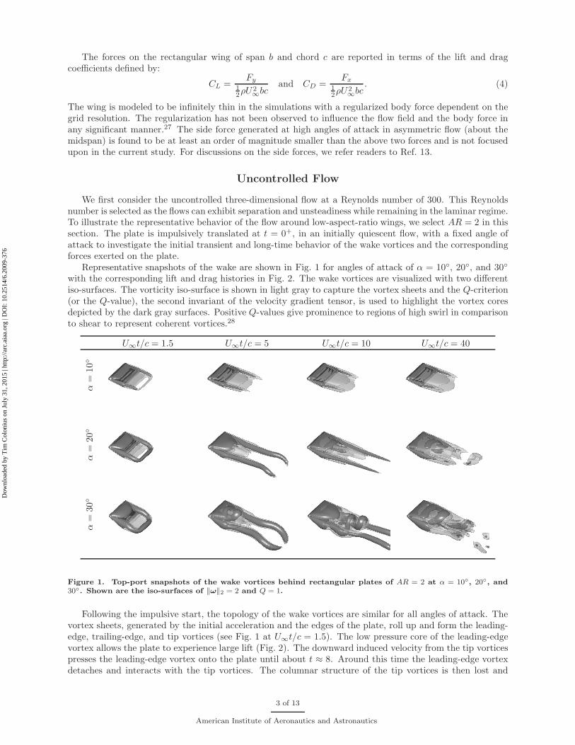
Representative snapshots of the wake are shown in Fig. 1 for angles of attack of α = 10◦, 20◦, and 30◦
with the corresponding lift and drag histories in Fig. 2. The wake vortices are visualized with two differentiso-surfaces. The vorticity iso-surface is shown in light gray to capture the vortex sheets and the Q-criterion(or the Q-value), the second invariant of the velocity gradient tensor, is used to highlight the vortex coresdepicted by the dark gray surfaces. Positive Q-values give prominence to regions of high swirl in comparisonto shear to represent coherent vortices.28
U∞t/c = 1.5 U∞t/c = 5 U∞t/c = 10 U∞t/c = 40
α=
10◦
α=
20◦
α=
30◦
Figure 1. Top-port snapshots of the wake vortices behind rectangular plates of AR = 2 at α = 10◦, 20◦, and30◦. Shown are the iso-surfaces of ‖ω‖2 = 2 and Q = 1.
Following the impulsive start, the topology of the wake vortices are similar for all angles of attack. Thevortex sheets, generated by the initial acceleration and the edges of the plate, roll up and form the leading-edge, trailing-edge, and tip vortices (see Fig. 1 at U∞t/c = 1.5). The low pressure core of the leading-edgevortex allows the plate to experience large lift (Fig. 2). The downward induced velocity from the tip vorticespresses the leading-edge vortex onto the plate until about t ≈ 8. Around this time the leading-edge vortexdetaches and interacts with the tip vortices. The columnar structure of the tip vortices is then lost and
3 of 13
American Institute of Aeronautics and Astronautics
Dow
nloa
ded
by T
im C
olon
ius
on J
uly
31, 2
015
| http
://ar
c.ai
aa.o
rg |
DO
I: 1
0.25
14/6
.200
9-37
6
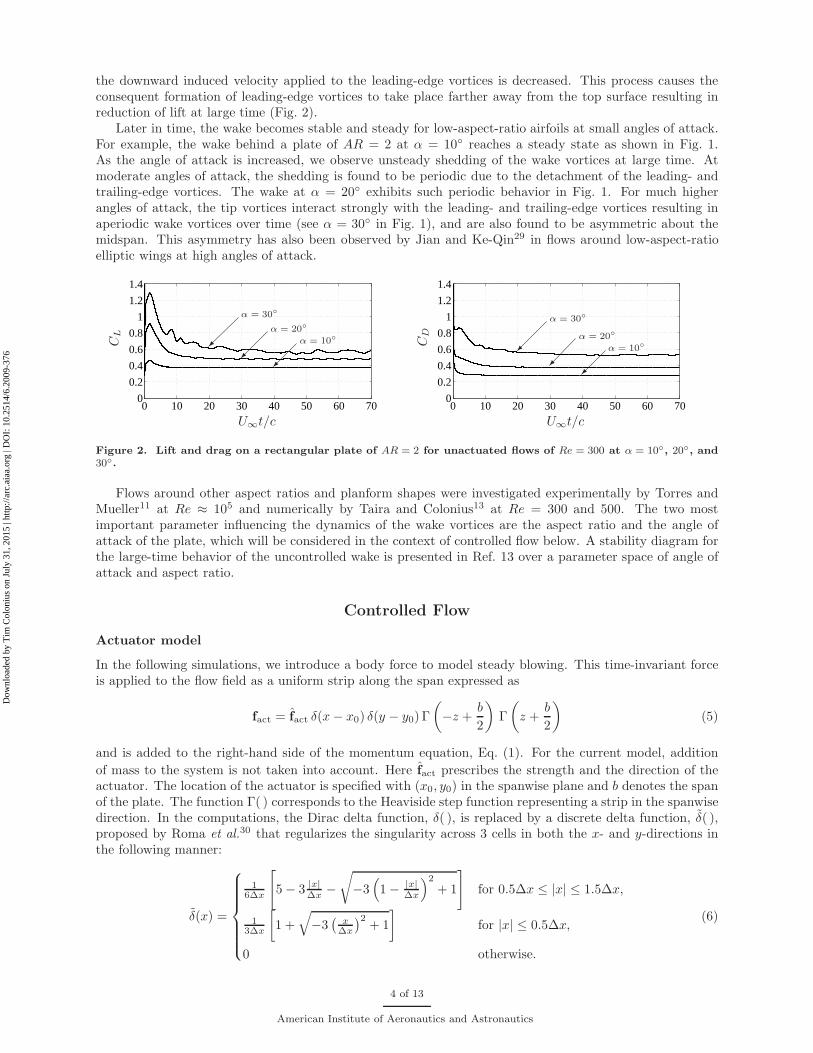
the downward induced velocity applied to the leading-edge vortices is decreased. This process causes theconsequent formation of leading-edge vortices to take place farther away from the top surface resulting inreduction of lift at large time (Fig. 2).
Later in time, the wake becomes stable and steady for low-aspect-ratio airfoils at small angles of attack.For example, the wake behind a plate of AR = 2 at α = 10◦ reaches a steady state as shown in Fig. 1.As the angle of attack is increased, we observe unsteady shedding of the wake vortices at large time. Atmoderate angles of attack, the shedding is found to be periodic due to the detachment of the leading- andtrailing-edge vortices. The wake at α = 20◦ exhibits such periodic behavior in Fig. 1. For much higherangles of attack, the tip vortices interact strongly with the leading- and trailing-edge vortices resulting inaperiodic wake vortices over time (see α = 30◦ in Fig. 1), and are also found to be asymmetric about themidspan. This asymmetry has also been observed by Jian and Ke-Qin29 in flows around low-aspect-ratioelliptic wings at high angles of attack.
0 10 20 30 40 50 60 700
0.2
0.4
0.6
0.8
1
1.2
1.4
α = 30◦
α = 20◦
α = 10◦
U∞t/c
CL
0 10 20 30 40 50 60 700
0.2
0.4
0.6
0.8
1
1.2
1.4
α = 30◦
α = 20◦
α = 10◦
U∞t/cC
D
Figure 2. Lift and drag on a rectangular plate of AR = 2 for unactuated flows of Re = 300 at α = 10◦, 20◦, and30◦.
Flows around other aspect ratios and planform shapes were investigated experimentally by Torres andMueller11 at Re ≈ 105 and numerically by Taira and Colonius13 at Re = 300 and 500. The two mostimportant parameter influencing the dynamics of the wake vortices are the aspect ratio and the angle ofattack of the plate, which will be considered in the context of controlled flow below. A stability diagram forthe large-time behavior of the uncontrolled wake is presented in Ref. 13 over a parameter space of angle ofattack and aspect ratio.
Controlled Flow
Actuator model
In the following simulations, we introduce a body force to model steady blowing. This time-invariant forceis applied to the flow field as a uniform strip along the span expressed as
fact = fact δ(x − x0) δ(y − y0) Γ
(
−z +b
2
)
Γ
(
z +b
2
)
(5)
and is added to the right-hand side of the momentum equation, Eq. (1). For the current model, addition
of mass to the system is not taken into account. Here fact prescribes the strength and the direction of theactuator. The location of the actuator is specified with (x0, y0) in the spanwise plane and b denotes the spanof the plate. The function Γ( ) corresponds to the Heaviside step function representing a strip in the spanwisedirection. In the computations, the Dirac delta function, δ( ), is replaced by a discrete delta function, δ( ),proposed by Roma et al.30 that regularizes the singularity across 3 cells in both the x- and y-directions inthe following manner:
δ(x) =
16∆x
[
5 − 3 |x|∆x −
√
−3(
1 − |x|∆x
)2
+ 1
]
for 0.5∆x ≤ |x| ≤ 1.5∆x,
13∆x
[
1 +
√
−3(
x∆x
)2+ 1
]
for |x| ≤ 0.5∆x,
0 otherwise.
(6)
4 of 13
American Institute of Aeronautics and Astronautics
Dow
nloa
ded
by T
im C
olon
ius
on J
uly
31, 2
015
| http
://ar
c.ai
aa.o
rg |
DO
I: 1
0.25
14/6
.200
9-37
6
The function is shown here for the x-direction with a mesh width of ∆x. This delta function is also used inthe immersed boundary projection method to represent the immersed boundary.
The discrete delta function is selected to use the smallest possible width for the actuator, which islimited by the resolution of the simulation. For the current actuator model, there is not a direct analog forthe physical slot width, since the simulated blowing does not exit through a slot. Hence, the modeled slotwidth is set to the characteristic length scale of the discrete delta function, σ = ∆x = 0.04c. Comparedto the typical slot widths of σ/c ≈ 0.01 used in flow control,31–33 the current slot width in our simulationsis slightly larger. Nonetheless the present forcing function is used to explore control techniques at this lowReynolds number.
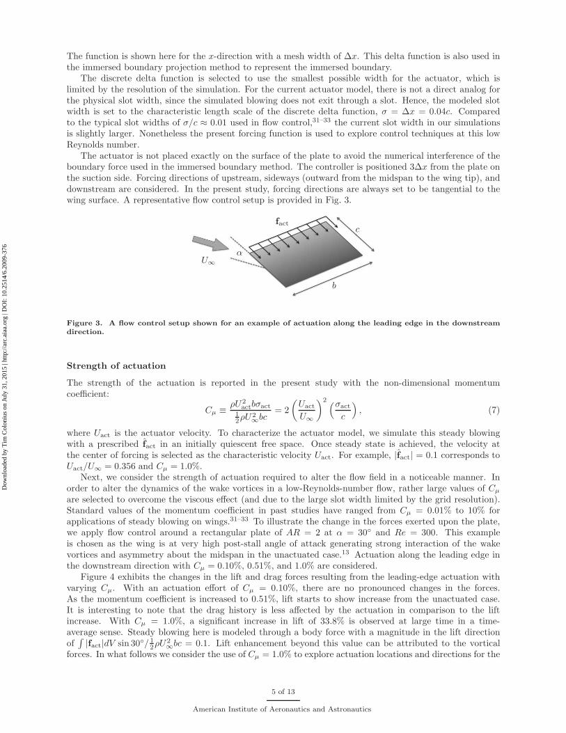
The actuator is not placed exactly on the surface of the plate to avoid the numerical interference of theboundary force used in the immersed boundary method. The controller is positioned 3∆x from the plate onthe suction side. Forcing directions of upstream, sideways (outward from the midspan to the wing tip), anddownstream are considered. In the present study, forcing directions are always set to be tangential to thewing surface. A representative flow control setup is provided in Fig. 3.
U∞
α
c
b
fact
Figure 3. A flow control setup shown for an example of actuation along the leading edge in the downstreamdirection.
Strength of actuation
The strength of the actuation is reported in the present study with the non-dimensional momentumcoefficient:
Cµ ≡ρU2
actbσact
12ρU2
∞bc= 2
(
Uact
U∞
)2(σact
c
)
, (7)
where Uact is the actuator velocity. To characterize the actuator model, we simulate this steady blowingwith a prescribed fact in an initially quiescent free space. Once steady state is achieved, the velocity atthe center of forcing is selected as the characteristic velocity Uact. For example, |fact| = 0.1 corresponds toUact/U∞ = 0.356 and Cµ = 1.0%.
Next, we consider the strength of actuation required to alter the flow field in a noticeable manner. Inorder to alter the dynamics of the wake vortices in a low-Reynolds-number flow, rather large values of Cµ
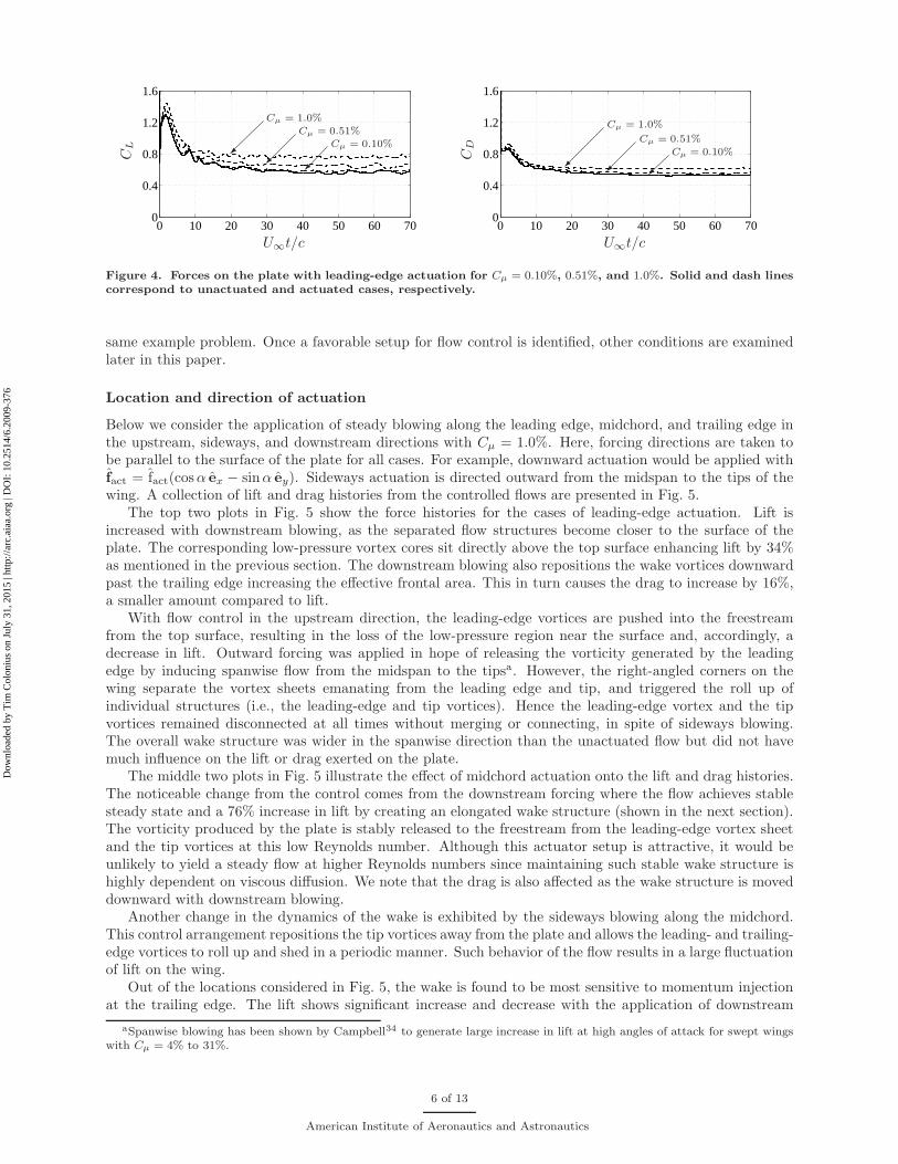
are selected to overcome the viscous effect (and due to the large slot width limited by the grid resolution).Standard values of the momentum coefficient in past studies have ranged from Cµ = 0.01% to 10% forapplications of steady blowing on wings.31–33 To illustrate the change in the forces exerted upon the plate,we apply flow control around a rectangular plate of AR = 2 at α = 30◦ and Re = 300. This exampleis chosen as the wing is at very high post-stall angle of attack generating strong interaction of the wakevortices and asymmetry about the midspan in the unactuated case.13 Actuation along the leading edge inthe downstream direction with Cµ = 0.10%, 0.51%, and 1.0% are considered.
Figure 4 exhibits the changes in the lift and drag forces resulting from the leading-edge actuation withvarying Cµ. With an actuation effort of Cµ = 0.10%, there are no pronounced changes in the forces.As the momentum coefficient is increased to 0.51%, lift starts to show increase from the unactuated case.It is interesting to note that the drag history is less affected by the actuation in comparison to the liftincrease. With Cµ = 1.0%, a significant increase in lift of 33.8% is observed at large time in a time-average sense. Steady blowing here is modeled through a body force with a magnitude in the lift directionof
∫
|fact|dV sin 30◦/ 12ρU2
∞bc = 0.1. Lift enhancement beyond this value can be attributed to the vorticalforces. In what follows we consider the use of Cµ = 1.0% to explore actuation locations and directions for the
5 of 13
American Institute of Aeronautics and Astronautics
Dow
nloa
ded
by T
im C
olon
ius
on J
uly
31, 2
015
| http
://ar
c.ai
aa.o
rg |
DO
I: 1
0.25
14/6
.200
9-37
6
0 10 20 30 40 50 60 700
0.4
0.8
1.2
1.6
Cµ = 1.0%
Cµ = 0.51%
Cµ = 0.10%
U∞t/c
CL
0 10 20 30 40 50 60 700
0.4
0.8
1.2
1.6
Cµ = 1.0%
Cµ = 0.51%
Cµ = 0.10%
U∞t/c
CD
Figure 4. Forces on the plate with leading-edge actuation for Cµ = 0.10%, 0.51%, and 1.0%. Solid and dash linescorrespond to unactuated and actuated cases, respectively.
same example problem. Once a favorable setup for flow control is identified, other conditions are examinedlater in this paper.
Location and direction of actuation
Below we consider the application of steady blowing along the leading edge, midchord, and trailing edge inthe upstream, sideways, and downstream directions with Cµ = 1.0%. Here, forcing directions are taken tobe parallel to the surface of the plate for all cases. For example, downward actuation would be applied withfact = fact(cosα ex − sinα ey). Sideways actuation is directed outward from the midspan to the tips of thewing. A collection of lift and drag histories from the controlled flows are presented in Fig. 5.
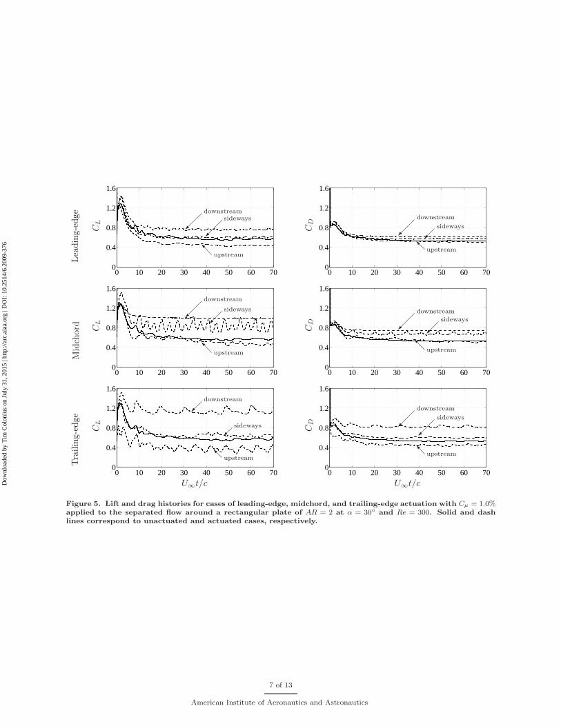
The top two plots in Fig. 5 show the force histories for the cases of leading-edge actuation. Lift isincreased with downstream blowing, as the separated flow structures become closer to the surface of theplate. The corresponding low-pressure vortex cores sit directly above the top surface enhancing lift by 34%as mentioned in the previous section. The downstream blowing also repositions the wake vortices downwardpast the trailing edge increasing the effective frontal area. This in turn causes the drag to increase by 16%,a smaller amount compared to lift.
With flow control in the upstream direction, the leading-edge vortices are pushed into the freestreamfrom the top surface, resulting in the loss of the low-pressure region near the surface and, accordingly, adecrease in lift. Outward forcing was applied in hope of releasing the vorticity generated by the leadingedge by inducing spanwise flow from the midspan to the tipsa. However, the right-angled corners on thewing separate the vortex sheets emanating from the leading edge and tip, and triggered the roll up ofindividual structures (i.e., the leading-edge and tip vortices). Hence the leading-edge vortex and the tipvortices remained disconnected at all times without merging or connecting, in spite of sideways blowing.The overall wake structure was wider in the spanwise direction than the unactuated flow but did not havemuch influence on the lift or drag exerted on the plate.
The middle two plots in Fig. 5 illustrate the effect of midchord actuation onto the lift and drag histories.The noticeable change from the control comes from the downstream forcing where the flow achieves stablesteady state and a 76% increase in lift by creating an elongated wake structure (shown in the next section).The vorticity produced by the plate is stably released to the freestream from the leading-edge vortex sheetand the tip vortices at this low Reynolds number. Although this actuator setup is attractive, it would beunlikely to yield a steady flow at higher Reynolds numbers since maintaining such stable wake structure ishighly dependent on viscous diffusion. We note that the drag is also affected as the wake structure is moveddownward with downstream blowing.
Another change in the dynamics of the wake is exhibited by the sideways blowing along the midchord.This control arrangement repositions the tip vortices away from the plate and allows the leading- and trailing-edge vortices to roll up and shed in a periodic manner. Such behavior of the flow results in a large fluctuationof lift on the wing.
Out of the locations considered in Fig. 5, the wake is found to be most sensitive to momentum injectionat the trailing edge. The lift shows significant increase and decrease with the application of downstream
aSpanwise blowing has been shown by Campbell34 to generate large increase in lift at high angles of attack for swept wingswith Cµ = 4% to 31%.
6 of 13
American Institute of Aeronautics and Astronautics
Dow
nloa
ded
by T
im C
olon
ius
on J
uly
31, 2
015
| http
://ar
c.ai
aa.o
rg |
DO
I: 1
0.25
14/6
.200
9-37
6
Lea
din
g-e
dge
0 10 20 30 40 50 60 700
0.4
0.8
1.2
1.6
downstream
sideways
I upstream
CL
0 10 20 30 40 50 60 700
0.4
0.8
1.2
1.6
downstream
sideways
Iupstream
CD
Mid
chord
0 10 20 30 40 50 60 700
0.4
0.8
1.2
1.6
downstream
sideways
I upstream
CL
0 10 20 30 40 50 60 700
0.4
0.8
1.2
1.6
downstream
sideways
I upstream
CD
Tra
ilin
g-e
dge
0 10 20 30 40 50 60 700
0.4
0.8
1.2
1.6
downstream
sideways
Iupstream
U∞t/c
CL
0 10 20 30 40 50 60 700
0.4
0.8
1.2
1.6
downstream
sideways
Iupstream
U∞t/c
CD
Figure 5. Lift and drag histories for cases of leading-edge, midchord, and trailing-edge actuation with Cµ = 1.0%applied to the separated flow around a rectangular plate of AR = 2 at α = 30◦ and Re = 300. Solid and dashlines correspond to unactuated and actuated cases, respectively.
7 of 13
American Institute of Aeronautics and Astronautics
Dow
nloa
ded
by T
im C
olon
ius
on J
uly
31, 2
015
| http
://ar
c.ai
aa.o
rg |
DO
I: 1
0.25
14/6
.200
9-37
6
and upstream forcing, respectively. The time-average lift is increased by a remarkable 100% for downstreamblowing. Such noticeable changes in forces are not realized for the sideways blowing at the trailing edge.
The reason for the strong influence of the actuation upon the forces is the direct modification ofthe trailing-edge vortex. Upstream and downstream blowing, respectively, encourages and discouragesthe interaction between the leading- and trailing-edge vortices. Below, we will further examine how thedownstream actuation at the trailing edge modifies the vortex dynamics in the vicinity of the wing andcontributes to lift enhancement.
To summarize, we have observed that steady blowing can change the dynamics of the wake vortices toincrease or decrease lift and drag. From the three locations considered, the trailing edge is observed to affectthe force on the wing in the most substantial manner. At all three actuator positions, steady blowing in thedownstream direction enhanced lift whereas the upstream direction reduced lift. The most effective actuatorfor the considered example is found to be at the trailing edge in the downstream direction, doubling in liftat large time from the change in the dynamics of the wake vortices.
Wake modification with actuation
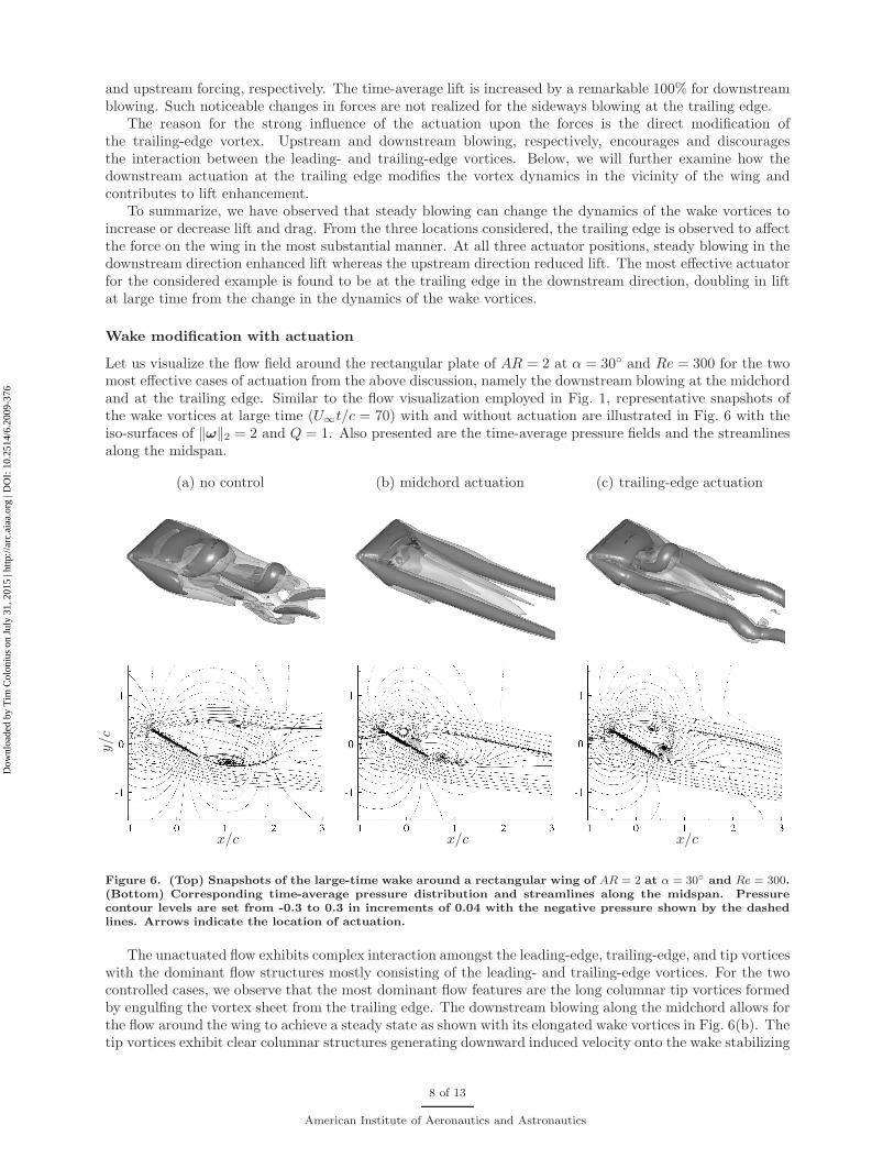
Let us visualize the flow field around the rectangular plate of AR = 2 at α = 30◦ and Re = 300 for the twomost effective cases of actuation from the above discussion, namely the downstream blowing at the midchordand at the trailing edge. Similar to the flow visualization employed in Fig. 1, representative snapshots ofthe wake vortices at large time (U∞t/c = 70) with and without actuation are illustrated in Fig. 6 with theiso-surfaces of ‖ω‖2 = 2 and Q = 1. Also presented are the time-average pressure fields and the streamlinesalong the midspan.
(a) no control (b) midchord actuation (c) trailing-edge actuation
x/c
y/c
x/c x/c
Figure 6. (Top) Snapshots of the large-time wake around a rectangular wing of AR = 2 at α = 30◦ and Re = 300.(Bottom) Corresponding time-average pressure distribution and streamlines along the midspan. Pressurecontour levels are set from -0.3 to 0.3 in increments of 0.04 with the negative pressure shown by the dashedlines. Arrows indicate the location of actuation.
The unactuated flow exhibits complex interaction amongst the leading-edge, trailing-edge, and tip vorticeswith the dominant flow structures mostly consisting of the leading- and trailing-edge vortices. For the twocontrolled cases, we observe that the most dominant flow features are the long columnar tip vortices formedby engulfing the vortex sheet from the trailing edge. The downstream blowing along the midchord allows forthe flow around the wing to achieve a steady state as shown with its elongated wake vortices in Fig. 6(b). Thetip vortices exhibit clear columnar structures generating downward induced velocity onto the wake stabilizing
8 of 13
American Institute of Aeronautics and Astronautics
Dow
nloa
ded
by T
im C
olon
ius
on J
uly
31, 2
015
| http
://ar
c.ai
aa.o
rg |
DO
I: 1
0.25
14/6
.200
9-37
6
the leading-edge vortex sheet. The vorticity within this sheet is diffused into the free stream in a steadfastmanner at this Reynolds number. In the case of downstream blowing at the trailing edge, the strengthenedtip vortices apply stronger downward induced velocity on the leading-edge vortices and let them roll up inclose neighborhood of the top surface of the plate as shown in Fig. 6(c). Hence the low-pressure cores fromthe roll-up provide lift enhancement.
In both cases the separation bubble with control visualized along the midspan have become smaller ina time-average sense compared to the unactuated case. Additionally, the streamlines are deflected furtherdownward with blowing, directly implying that lift on the wing is increased based on the momentum balance.Note that the roll-up motion at the trailing edge from the unactuated case is now attenuated with steadyblowing. The removal of such roll-up seems to be the key factor in modifying the dynamics of the wake.
�tip vortex
�
trailing-edgevortex sheet
�
leading-edge vortex
�
actuator
downwardinduced vel.
downwardinduced vel.
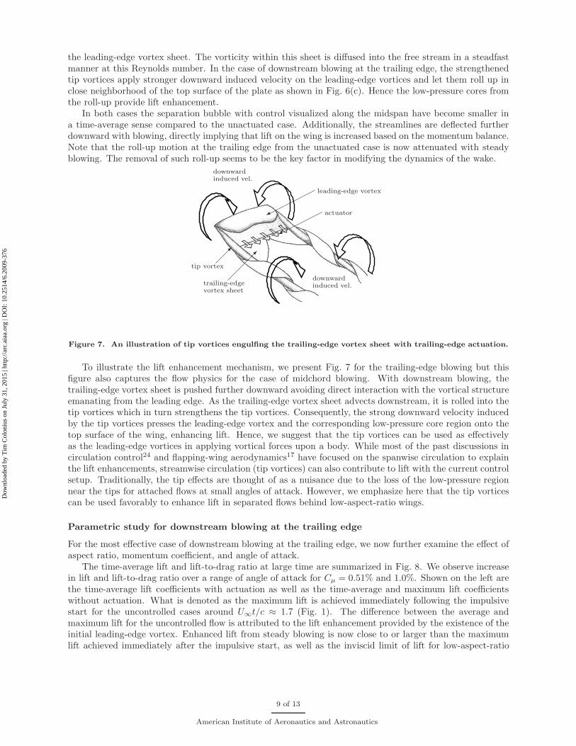
Figure 7. An illustration of tip vortices engulfing the trailing-edge vortex sheet with trailing-edge actuation.
To illustrate the lift enhancement mechanism, we present Fig. 7 for the trailing-edge blowing but thisfigure also captures the flow physics for the case of midchord blowing. With downstream blowing, thetrailing-edge vortex sheet is pushed further downward avoiding direct interaction with the vortical structureemanating from the leading edge. As the trailing-edge vortex sheet advects downstream, it is rolled into thetip vortices which in turn strengthens the tip vortices. Consequently, the strong downward velocity inducedby the tip vortices presses the leading-edge vortex and the corresponding low-pressure core region onto thetop surface of the wing, enhancing lift. Hence, we suggest that the tip vortices can be used as effectivelyas the leading-edge vortices in applying vortical forces upon a body. While most of the past discussions incirculation control24 and flapping-wing aerodynamics17 have focused on the spanwise circulation to explainthe lift enhancements, streamwise circulation (tip vortices) can also contribute to lift with the current controlsetup. Traditionally, the tip effects are thought of as a nuisance due to the loss of the low-pressure regionnear the tips for attached flows at small angles of attack. However, we emphasize here that the tip vorticescan be used favorably to enhance lift in separated flows behind low-aspect-ratio wings.
Parametric study for downstream blowing at the trailing edge
For the most effective case of downstream blowing at the trailing edge, we now further examine the effect ofaspect ratio, momentum coefficient, and angle of attack.
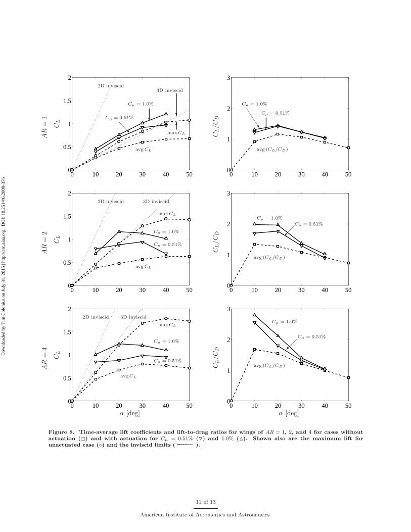
The time-average lift and lift-to-drag ratio at large time are summarized in Fig. 8. We observe increasein lift and lift-to-drag ratio over a range of angle of attack for Cµ = 0.51% and 1.0%. Shown on the left arethe time-average lift coefficients with actuation as well as the time-average and maximum lift coefficientswithout actuation. What is denoted as the maximum lift is achieved immediately following the impulsivestart for the uncontrolled cases around U∞t/c ≈ 1.7 (Fig. 1). The difference between the average andmaximum lift for the uncontrolled flow is attributed to the lift enhancement provided by the existence of theinitial leading-edge vortex. Enhanced lift from steady blowing is now close to or larger than the maximumlift achieved immediately after the impulsive start, as well as the inviscid limit of lift for low-aspect-ratio
9 of 13
American Institute of Aeronautics and Astronautics
Dow
nloa
ded
by T
im C
olon
ius
on J
uly
31, 2
015
| http
://ar
c.ai
aa.o
rg |
DO
I: 1
0.25
14/6
.200
9-37
6
airfoilsb.Let us examine the performance of the actuator for the wing of AR = 1. In Fig. 8, we observe that the
time-average lift with control is increased past the maximum lift achieved by the uncontrolled transient flowfor almost all cases considered. Again, this increase is not from the addition of the numerical body forceused to represent steady blowing. The direct contributions to lift from such modeled blowing are 0.1 sinαand 0.2 sinα for Cµ = 0.51% and 1.0%, respectively, and do not account for the full increase realized here.The lift increase seen here results mostly from the modification of the wake vortices.
With flow control around a wing of AR = 2, the time-average lift is further increased especially aroundα ≈ 20◦. For higher α, the interaction of the wake vortices reduce the level of increase but still achieves anoverall enhancement for both forcing magnitudes. A similar trend holds for the case of AR = 4 with peakperformance around α ≈ 20◦. In the case of AR = 1, the tip vortices cover almost the entire span withoutleaving much room for the leading-edge vortex to stay near the top surface. The lift-to-drag ratio does notshow a large enhancement for AR = 1 when compared to the higher-aspect-ratio wings. In the case of largeraspect-ratio wings, we observe large increase in lift due to the large extent of the leading-edge vortex overthe span.
Once the flow becomes overwhelmed with strong nonlinear interaction of the wake vortices at highangles of attack (i.e., α ≈ 40◦), the amount of lift enhancement is reduced. In such high-angle-of-attackflows, downstream blowing is not able to keep the trailing-edge vortex sheet from interacting with othervortices and results in no significant increase in the strength of the tip vortices (unless perhaps with muchstronger blowing). Nonetheless, this actuator setup seems to be effective overall for various regimes (steadyand unsteady periodic/aperiodic states as discussed in the uncontrolled flow section). The strip of steadyblowing at the trailing edge is especially attractive for AR & 2 and α . 30◦ as the lift-to-drag ratio showssubstantial increase as well.
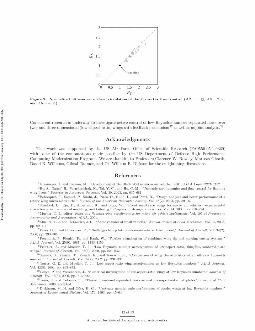
To demonstrate that the increase in lift is attributed to the strengthening of the tip vortices due tothe downstream trailing-edge actuation, we compute the relative increase in time-average (avg) lift andstreamwise circulation of the tip vortex:
RL ≡ avgCL/avgC∗L and RΓ ≡ avgΓ/avgΓ∗, (8)
respectively, where ∗ is used here to denote the unactuated results. The circulation of the tip vortex isevaluated at a streamwise location of x/c = 2.5 using Γ =
∮
u · dl, where the contour is chosen to enclosethe patch of vorticity (tip vortex) above 1% of the maximum value. These relative increases are plottedagainst each other in Fig. 9 for actuated cases with Cµ = 0.51% and 1.0% around wings of AR = 1, 2, and4. Based on Fig. 9, the correlation coefficient ρ(RΓ, RL) is found to be 0.952, which indeed suggests thatstrengthening the tip vortices have positive influence on the lift enhancement for low-aspect-ratio wings atpost-stall angles of attack. With the current flow control arrangement, an increase in lift as high as about2.5 times the unactuated value has been achieved for one case.
Conclusion
We considered the application of steady blowing to separated flows behind low-aspect-ratio rectangularwings at a low Reynolds number. The objective of the flow control was to enhance lift at post-stall anglesof attack by changing the three-dimensional dynamics of the wake vortices. Flow control was simulatedwith the immersed boundary projection method and the actuator was modeled by a body force near the topsurface of the wing to represent steady tangential blowing. Various setups were considered and downstreamblowing along the trailing edge was found to be most effective in enhancing lift. This controller strengthenedthe tip vortices by engulfing the trailing-edge vortex sheet to increase the downward induced velocity ontothe leading-edge vortices. The low-pressure cores of the leading-edge vortices moved closer to the top surfacecontributing to the increase in lift. In some ways, the present control mechanism is similar to circulationcontrol.24 However, instead of simply increasing the spanwise circulation, we have increased the streamwisecirculation of the tip vortices here. The tip vortices that are traditionally considered as an aerodynamicnuisance, have been used in favor to increase lift in post-stall flows for the considered low-aspect-ratio wings.
bThe three-dimensional inviscid lift limit, CL = 2πα/(q
1 + (2/AR)2 + 2/AR), was derived by Helmbold35 from the lifting
surface theory for elliptic wings and is shown to be in remarkable agreement with low-aspect-ratio wings of AR < 4. Lift forrectangular planforms of 0.5 ≤ AR ≤ 6 is accurately predicted with this model.36
10 of 13
American Institute of Aeronautics and Astronautics
Dow
nloa
ded
by T
im C
olon
ius
on J
uly
31, 2
015
| http
://ar
c.ai
aa.o
rg |
DO
I: 1
0.25
14/6
.200
9-37
6
0 10 20 30 40 500
0.5
1
1.5
2
Cµ = 0.51%
R
Cµ = 1.0%
?
maxCL
6
avg CL
3D inviscid
?
2D inviscid
CL
AR
=1
0 10 20 30 40 500
1
2
3
Cµ = 0.51%
?
Cµ = 1.0%
^
avg (CL/CD)
CL/C
D
0 10 20 30 40 500
0.5
1
1.5
2
Cµ = 0.51%
Cµ = 1.0%
max CL
avg CL
3D inviscid2D inviscid
CL
AR
=2
0 10 20 30 40 500
1
2
3
Cµ = 0.51%
Cµ = 1.0%
avg (CL/CD)
CL/C
D
0 10 20 30 40 500
0.5
1
1.5
2
Cµ = 0.51%
Cµ = 1.0%
max CL
avg CL
3D inviscid2D inviscid
α [deg]
CL
AR
=4
0 10 20 30 40 500
1
2
3
Cµ = 0.51%
Cµ = 1.0%
avg (CL/CD)
α [deg]
CL/C
D
Figure 8. Time-average lift coefficients and lift-to-drag ratios for wings of AR = 1, 2, and 4 for cases withoutactuation (�) and with actuation for Cµ = 0.51% (▽) and 1.0% (△). Shown also are the maximum lift forunactuated case (◦) and the inviscid limits ( ).
11 of 13
American Institute of Aeronautics and Astronautics
Dow
nloa
ded
by T
im C
olon
ius
on J
uly
31, 2
015
| http
://ar
c.ai
aa.o
rg |
DO
I: 1
0.25
14/6
.200
9-37
6
0 0.5 1 1.5 2 2.5 30
0.5
1
1.5
2
2.5
3
Ibaseline
RΓR
L
Figure 9. Normalized lift over normalized circulation of the tip vortex from control (AR = 1: �, AR = 2: ◦,and AR = 4: △).
Concurrent research is underway to investigate active control of low-Reynolds-number separated flows overtwo- and three-dimensional (low-aspect-ratio) wings with feedback mechanism37 as well as adjoint analysis.38
Acknowledgments
This work was supported by the US Air Force Office of Scientific Research (FA9550-05-1-0369)with some of the computations made possible by the US Department of Defense High PerformanceComputing Modernization Program. We are thankful to Professors Clarence W. Rowley, Morteza Gharib,David R. Williams, Gilead Tadmor, and Dr. William B. Dickson for the enlightening discussions.
References
1Grasmeyer, J. and Keenon, M., “Development of the Black Widow micro air vehicle,” 2001, AIAA Paper 2001-0127.2Ho, S., Nassef, H., Pornsinsirirak, N., Tai, Y.-C., and Ho, C.-M., “Unsteady aerodynamics and flow control for flapping
wing flyers,” Progress in Aerospace Sciences, Vol. 39, 2003, pp. 635–681.3Bohorquez, F., Samuel, P., Sirohi, J., Pines, D., Rudd, L., and Perel, R., “Design analysis and hover performance of a
rotary wing micro air vehicle,” Journal of the American Helicopter Society , Vol. 48(2), 2003, pp. 80–90.4Stanford, B., Ifju, P., Albertani, R., and Shyy, W., “Fixed membrane wings for micro air vehicles: experimental
characterization, numerical modeling, and tailoring,” Progress in Aerospace Sciences, Vol. 44, 2008, pp. 258–294.5Mueller, T. J., editor, Fixed and flapping wing aerodynamics for micro air vehicle applications, Vol. 195 of Progress in
Astronautics and Aeronautics, AIAA, 2001.6Mueller, T. J. and DeLaurier, J. D., “Aerodynamics of small vehicles,” Annual Review of Fluid Mechanics, Vol. 35, 2003,
pp. 89–111.7Pines, D. J. and Bohorquez, F., “Challenges facing future micro-air-vehicle development,” Journal of Aircraft , Vol. 34(2),
2006, pp. 290–305.8Freymuth, P., Finaish, F., and Bank, W., “Further visualization of combined wing tip and starting vortex systems,”
AIAA Journal , Vol. 25(9), 1987, pp. 1153–1159.9Pelletier, A. and Mueller, T. J., “Low Reynolds number aerodynamics of low-aspect-ratio, thin/flat/cambered-plate
wings,” Journal of Aircraft , Vol. 37(5), 2000, pp. 825–832.10Sunada, S., Yasuda, T., Yasuda, K., and Kawachi, K., “Comparison of wing characteristics at an ultralow Reynolds
number,” Journal of Aircraft , Vol. 39(2), 2002, pp. 331–338.11Torres, G. E. and Mueller, T. J., “Low-aspect-ratio wing aerodynamics at low Reynolds numbers,” AIAA Journal ,
Vol. 42(5), 2004, pp. 865–873.12Cosyn, P. and Vierendeels, J., “Numerical investigation of low-aspect-ratio wings at low Reynolds numbers,” Journal of
Aircraft , Vol. 43(3), 2006, pp. 713–722.13Taira, K. and Colonius, T., “Three-dimensional separated flows around low-aspect-ratio flat plates,” Journal of Fluid
Mechanics, 2008, accepted.14Dickinson, M. H. and Gotz, K. G., “Unsteady aerodynamic performance of model wings at low Reynolds numbers,”
Journal of Experimental Biology , Vol. 174, 1993, pp. 45–64.
12 of 13
American Institute of Aeronautics and Astronautics
Dow
nloa
ded
by T
im C
olon
ius
on J
uly
31, 2
015
| http
://ar
c.ai
aa.o
rg |
DO
I: 1
0.25
14/6
.200
9-37
6
15Ellington, C. P., van den Berg, C., Willmott, A. P., and Thomas, A. L. R., “Leading-edge vortices in insect flight,”Nature, Vol. 384, 1996, pp. 626–630.
16Birch, J. M. and Dickinson, M. H., “Spanwise flow and the attachment of the leading-edge vortex on insect wings,”Nature, Vol. 412, 2001, pp. 729–733.
17Birch, J. M., Dickson, W. B., and Dickinson, M. H., “Force production and flow structure of the leading edge vortex onflapping wings at high and low Reynolds numbers,” Journal of Experimental Biology , Vol. 207, 2004, pp. 1063–1072.
18Poelma, C., Dickson, W. B., and Dickinson, M. H., “Time-resolved reconstruction of the full velocity field around adynamically-scaled flapping wing,” Experiments in Fluids, Vol. 41, 2006, pp. 213–225.
19Choi, H., Jeon, W.-P., and Kim, J., “Control of Flow Over a Bluff Body,” Annual Review of Fluid Mechanics, Vol. 40,2008, pp. 113–139.
20Watkins, S., Milbank, J., Loxton, B. J., and Melbourne, W. H., “Atmospheric winds and their implications for microairvehicles,” AIAA Journal , Vol. 44(11), 2006, pp. 2591–2600.
21Seifert, A., Darabi, A., and Wygnanski, I., “Delay of airfoil stall by periodic excitation,” Journal of Aircraft , Vol. 33(4),1996, pp. 691–698.
22Greenblatt, D., Neuburger, D., and Wygnanski, I., “Dynamic stall control by intermittent periodic excitation,” Journal
of Aircraft , Vol. 38(1), 2001, pp. 188–190.23Seifert, A., Greenblatt, D., and Wygnanski, I. J., “Active separation control: an overview of Reynolds and Mach numbers
effects,” Aerospace Science and Technology , Vol. 8, 2004, pp. 569–582.24Englar, R. J., “Circulation control pneumatic aerodynamics: blown force and moment augmentation and modification;
past, present & future,” 2000, AIAA Paper 2000-2541.25Joslin, R. D. and Jones, G. S., editors, Applications of Circulation Control Technologies, Vol. 214 of Progress in
Astronautics and Aeronautics, AIAA, 2006.26Taira, K. and Colonius, T., “The immersed boundary method: a projection approach,” Journal of Computational Physics,
Vol. 225, 2007, pp. 2118–2137.27Taira, K., Dickson, W. B., Colonius, T., Dickinson, M. H., and Rowley, C. W., “Unsteadiness in flow over a flat plate at
angle-of-attack at low Reynolds numbers,” 2007, AIAA Paper 2007-710.28Hunt, J. C. R., Wray, A. A., and Moin, P., “Eddies, stream, and convergence zones in turbulent flows,” Tech. Rep.
CTR-S88, Center for Turbulence Research, 1988.29Jian, T. and Ke-Qin, Z., “Numerical and experimental study of flow structure of low-aspect-ratio wing,” Journal of
Aircraft , Vol. 41(5), 2004, pp. 1196–1201.30Roma, A. M., Peskin, C. S., and Berger, M. J., “An adaptive version of the immersed boundary method,” Journal of
Computational Physics, Vol. 153, 1999, pp. 509–534.31Lee, C. S., Tavella, D., Woods, N. J., and Roberts, L., “Flow structure and scaling laws in lateral wing-tip blowing,”
AIAA Journal , Vol. 27(8), 1989, pp. 1002–1007.32Duraisamy, K. and Baeder, J. D., “Numerical simulation of the effects of spanwise blowing on tip vortex formation,”
Journal of Aircraft , Vol. 43(4), 2006, pp. 996–1006.33Holloway, A. G. L. and Richardson, S., “Development of a trailing vortex formed with spanwise tip jets,” Journal of
Aircraft , Vol. 44(3), 2007, pp. 845–857.34Campbell, J. F., “Augmentation of vortex lift by spanwise blowing,” Journal of Aircraft , Vol. 13(9), 1976, pp. 727–732.35Helmbold, H. B., “Der unverwundene ellipsenflugel als tragende flanche,” Tech. rep., Jahrbuch 1942 der Deutch
Luftfahrtforsch, 1942.36Anderson, J. D., Aircraft performance and design, McGraw-Hill, Boston, 1999.37Joe, W. T., Taira, K., Colonius, T., MacMynowski, D. G., and Tadmor, G., “Closed-loop control of vortex shedding on
a two-dimensional flat-plate airfoil at a low Reynolds number,” 2008, AIAA Paper 2008-634.38Ahuja, S. and Rowley, C. W., “Low-dimensional models for feedback stabilization of unstable steady states,” 2008, AIAA
Paper 2008-553.
13 of 13
American Institute of Aeronautics and Astronautics
Dow
nloa
ded
by T
im C
olon
ius
on J
uly
31, 2
015
| http
://ar
c.ai
aa.o
rg |
DO
I: 1
0.25
14/6
.200
9-37
6