
On the Dynamics of a Planetary Transmission for Renewable ...
10
On the Dynamics of a Planetary Transmission for Renewable Energy Systems JALIU CODRUTA, SAULESCU RADU, DIACONESCU DORIN, NEAGOE MIRCEA, CLIMESCU OLIVER Product Design and Robotics Department University Transilvania of Brasov Address Eroilor 29, Brasov ROMANIA [email protected] http://dpr.unitbv.ro/ Abstract: - The speed increaser placed between a turbine and a generator in a small hydro plant has to multiply the input speed so that the generator to function at its best efficiency. The analyzed speed increaser is an innovative planetary chain transmission that was proposed by the authors. The dynamic model of the chain speed increaser is presented in the paper based on Lagrange and Newton-Euler methods. The dynamic modeling allows the establishment of the working point in stationary regime for the turbine – speed increaser – generator assembly. The results guarantee the good functioning of the physical prototype of small hydropower plant in certain conditions. Key-Words: - planetary speed increaser, dynamics, numerical simulation, small hydro. 1 Introduction Small hydropower plants can operate with a good efficiency for different combinations of mechanical and electric components, depending upon the site requirements and design criteria [12]. The first step in designing the electro-mechanical equipment consists in the selection of the best turbine for the particular hydro site, depending on the site characteristics, the available water flow and stream head, as well as on the power required. Selection also depends on the speed at which it is desired to run the generator. Usually, the speed increasers from the small hydropower plants have to multiply the angular speed of the turbine shaft from 3 to 5 times [5, 7, 13] to meet the requirements of the generator speed. This is because in many cases, particularly in the lowest power range, turbines run at less than 700 rot/min requiring a speed increaser to meet the 1000 – 4000 rot/min of electric generators [5,12,13]. Fig. 1. The purchased Turgo turbine transmission that was proposed by the authors [9]. The solution is under certification and consists in a chain planetary set and a pin coupling (see Fig. 2). The proposed speed increaser ensures interchangeability and an easier replacement of the active components, has a reduced overall size, ensures reduced wears and, implicitly, a significant increase of the efficiency, as well as a simplified manufacturing technology due to the use of a chain and of normalized sprockets. The authors are designing a small hydropower plant to be implemented on a river from Brasov region. This mountain area is characterized by short rivers, with medium and high heads, medium and low values of the water flow due to the low quantity of precipitation, and high fluctuations of the flow due to snow melting. Based on the measurements of flow and head performed on some of the rivers from this region, it was decided to design an off-grid small hydropower plant equipped with a Turgo turbine (Fig. 1) that suits the site requirements. The paper presents the dynamic modeling of the planetary chain speed increaser, as the first step in the design of the small hydropower plant control system and a certification of the good functioning in real conditions of the plant electro-mechanical equipment. First, the paper approaches the appropriate kinematical and The speed increaser placed between the Turgo turbine and the generator has to multiply the input speed 3 times so that the generator to function at its best efficiency. The speed increaser is an innovative planetary chain WSEAS TRANSACTIONS on APPLIED and THEORETICAL MECHANICS Jaliu Codruta, Saulescu Radu, Diaconescu Dorin, Neagoe Mircea, Climescu Oliver ISSN: 1991-8747 146 Issue 2, Volume 5, April 2010
Transcript of On the Dynamics of a Planetary Transmission for Renewable ...

On the Dynamics of a Planetary Transmission for Renewable Energy Systems
JALIU CODRUTA, SAULESCU RADU, DIACONESCU DORIN,
NEAGOE MIRCEA, CLIMESCU OLIVER Product Design and Robotics Department
University Transilvania of Brasov Address Eroilor 29, Brasov
ROMANIA [email protected] http://dpr.unitbv.ro/
Abstract: - The speed increaser placed between a turbine and a generator in a small hydro plant has to multiply the input speed so that the generator to function at its best efficiency. The analyzed speed increaser is an innovative planetary chain transmission that was proposed by the authors. The dynamic model of the chain speed increaser is presented in the paper based on Lagrange and Newton-Euler methods. The dynamic modeling allows the establishment of the working point in stationary regime for the turbine – speed increaser – generator assembly. The results guarantee the good functioning of the physical prototype of small hydropower plant in certain conditions. Key-Words: - planetary speed increaser, dynamics, numerical simulation, small hydro. 1 Introduction Small hydropower plants can operate with a good efficiency for different combinations of mechanical and electric components, depending upon the site requirements and design criteria [12]. The first step in designing the electro-mechanical equipment consists in the selection of the best turbine for the particular hydro site, depending on the site characteristics, the available water flow and stream head, as well as on the power required. Selection also depends on the speed at which it is desired to run the generator. Usually, the speed increasers from the small hydropower plants have to multiply the angular speed of the turbine shaft from 3 to 5 times [5, 7, 13] to meet the requirements of the generator speed. This is because in many cases, particularly in the lowest power range, turbines run at less than 700 rot/min requiring a speed increaser to meet the 1000 – 4000 rot/min of electric generators [5,12,13].
Fig. 1. The purchased Turgo turbine
transmission that was proposed by the authors [9]. The solution is under certification and consists in a chain planetary set and a pin coupling (see Fig. 2). The proposed speed increaser ensures interchangeability and an easier replacement of the active components, has a reduced overall size, ensures reduced wears and, implicitly, a significant increase of the efficiency, as well as a simplified manufacturing technology due to the use of a chain and of normalized sprockets.
The authors are designing a small hydropower plant to be implemented on a river from Brasov region. This mountain area is characterized by short rivers, with medium and high heads, medium and low values of the water flow due to the low quantity of precipitation, and high fluctuations of the flow due to snow melting. Based on the measurements of flow and head performed on some of the rivers from this region, it was decided to design an off-grid small hydropower plant equipped with a Turgo turbine (Fig. 1) that suits the site requirements.
The paper presents the dynamic modeling of the planetary chain speed increaser, as the first step in the design of the small hydropower plant control system and a certification of the good functioning in real conditions of the plant electro-mechanical equipment. First, the paper approaches the appropriate kinematical and
The speed increaser placed between the Turgo turbine and the generator has to multiply the input speed 3 times so that the generator to function at its best efficiency. The speed increaser is an innovative planetary chain
WSEAS TRANSACTIONS on APPLIED and THEORETICAL MECHANICSJaliu Codruta, Saulescu Radu, Diaconescu Dorin, Neagoe Mircea, Climescu Oliver
ISSN: 1991-8747 146 Issue 2, Volume 5, April 2010
dynamic features of the speed increaser (internal transmission ratio, multiplication ratio, internal efficiency and the speed increaser efficiency). Then the paper presents the dynamic modeling of the turbine-speed increaser-generator assembly: the working point in stationary regime and the motion equations are established and validated based both on Lagrange and Newton-Euler methods. The dynamic response is obtained by means of Matlab-Simulink software.
( ) ⎟⎟⎠
⎞⎜⎜⎝
⎛++=⋅===
2
3H23
H12
H3
H1H130 z
z1iiii
ωω
(1)
03
31
3
1331 1 ii
H
HH
HH −=
ω−ω−ω
=ωω
= (2)
, [1, 4] 9452.095.0995.0H
23H12
H130 =⋅=⋅== ηηηη
The prototype of the speed increaser will be manufactured and tested into the Turgo assembly. The validation of the theoretical results certifies the good functioning of the physical prototype of small hydropower plant in the real conditions of Brasov region.
0
w00
113
H3H3H1 i1
i1TT
−−
=−
==η
ωω
ηη (3)
where: is the transmission ratio from element x to element y, while element z is considered blocked;
zxyi
xyω represents the relative speed between elements x and y, and w from rel. (3) is given by [4]:
( ) ⎟⎟
⎠
⎞⎜⎜⎝
⎛−
−=⎟⎟⎠
⎞⎜⎜⎝
⎛−
−=−=0
0
113
1H11H1 i1
isgnT
TsgnTsgnwωω
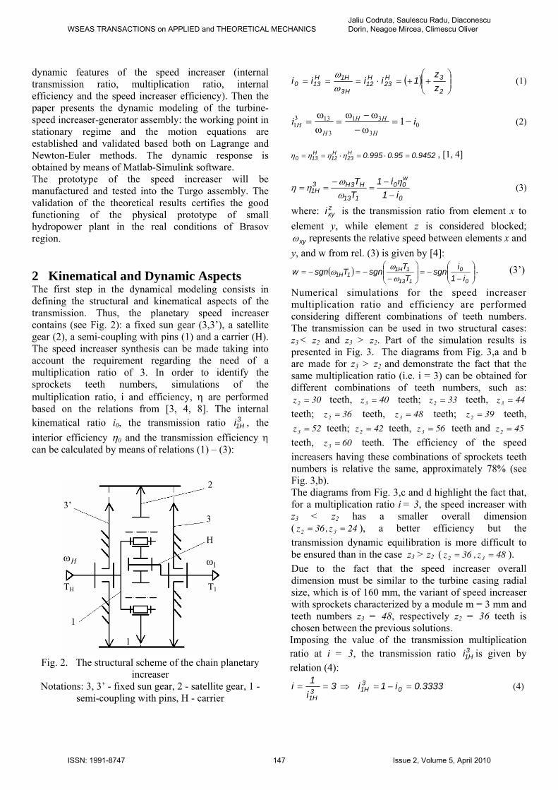
ω . (3’) 2 Kinematical and Dynamic Aspects The first step in the dynamical modeling consists in defining the structural and kinematical aspects of the transmission. Thus, the planetary speed increaser contains (see Fig. 2): a fixed sun gear (3,3’), a satellite gear (2), a semi-coupling with pins (1) and a carrier (H). The speed increaser synthesis can be made taking into account the requirement regarding the need of a multiplication ratio of 3. In order to identify the sprockets teeth numbers, simulations of the multiplication ratio, i and efficiency, η are performed based on the relations from [3, 4, 8]. The internal kinematical ratio i0, the transmission ratio , the interior efficiency η0 and the transmission efficiency η can be calculated by means of relations (1) – (3):
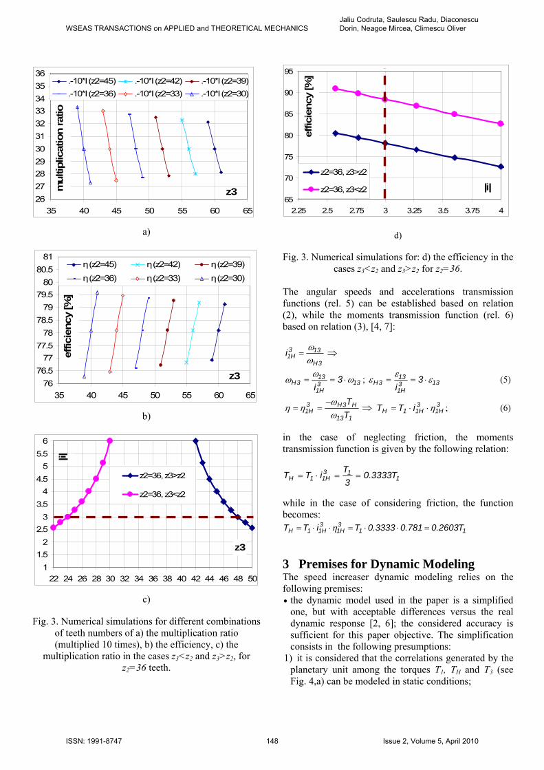
Numerical simulations for the speed increaser multiplication ratio and efficiency are performed considering different combinations of teeth numbers. The transmission can be used in two structural cases: z3 < z2 and z3 > z2. Part of the simulation results is presented in Fig. 3. The diagrams from Fig. 3,a and b are made for z3 > z2 and demonstrate the fact that the same multiplication ratio (i.e. i = 3) can be obtained for different combinations of teeth numbers, such as:
teeth, teeth; teeth, 30z2 = 40z3 = 33z2 = 44z3 = teeth; teeth, teeth; teeth, 36z2 = 48z3 = 39z2 =3
H1i teeth; teeth, teeth and 52z3 = 42z2 = 56z3 = 45z2 = teeth, 60z3 = teeth. The efficiency of the speed increasers having these combinations of sprockets teeth numbers is relative the same, approximately 78% (see Fig. 3,b).
2
3
H
3’
1
Hω 1ω
T1 TH
1
The diagrams from Fig. 3,c and d highlight the fact that, for a multiplication ratio i = 3, the speed increaser with z3 < z2 has a smaller overall dimension ( 24z,36z 32 == ), a better efficiency but the transmission dynamic equilibration is more difficult to be ensured than in the case z3 > z2 ( ). 48z,36z 32 ==Due to the fact that the speed increaser overall dimension must be similar to the turbine casing radial size, which is of 160 mm, the variant of speed increaser with sprockets characterized by a module m = 3 mm and teeth numbers z3 = 48, respectively z2 = 36 teeth is chosen between the previous solutions. Imposing the value of the transmission multiplication ratio at i = 3, the transmission ratio is given by relation (4):
3H1i
Fig. 2. The structural scheme of the chain planetary increaser
3i1i3H1
==Notations: 3, 3’ - fixed sun gear, 2 - satellite gear, 1 - semi-coupling with pins, H - carrier
(4) 3333.0i1i 03H1 =−=⇒
WSEAS TRANSACTIONS on APPLIED and THEORETICAL MECHANICSJaliu Codruta, Saulescu Radu, Diaconescu Dorin, Neagoe Mircea, Climescu Oliver
ISSN: 1991-8747 147 Issue 2, Volume 5, April 2010
65
70
75
80
85
90
95
2.25 2.5 2.75 3 3.25 3.5 3.75 4
|i|
effic
ienc
y [%
]
z2=36, z3>z2
z2=36, z3<z22627282930313233343536
35 40 45 50 55 60 65
z3mul
tiplic
atio
n ra
tio
.-10*I (z2=45) .-10*I (z2=42) .-10*I (z2=39)
.-10*I (z2=36) .-10*I (z2=33) .-10*I (z2=30)
a) d)
7676.5
7777.5
7878.5
7979.5
8080.5
81
35 40 45 50 55 60 65
z3
effic
ienc
y [%
]
η (z2=45) η (z2=42) η (z2=39)
η (z2=36) η (z2=33) η (z2=30)
Fig. 3. Numerical simulations for: d) the efficiency in the cases z3<z2 and z3>z2 for z2=36.
The angular speeds and accelerations transmission functions (rel. 5) can be established based on relation (2), while the moments transmission function (rel. 6) based on relation (3), [4, 7]:
3H
133H1i ω
ω= ⇒
133H1
133H 3
iωωω ⋅== 133
H1
133H 3
iεεε ⋅==; (5)
113
H3H3H1 T
Tωω
ηη−
==b)
11.5
22.5
33.5
44.5
55.5
6
22 24 26 28 30 32 34 36 38 40 42 44 46 48 50
z3
|i|
z2=36, z3>z2
z2=36, z3<z2
c)
Fig. 3. Numerical simulations for different combinations of teeth numbers of a) the multiplication ratio (multiplied 10 times), b) the efficiency, c) the
multiplication ratio in the cases z3<z2 and z3>z2, for z2=36 teeth.
⇒ ; (6) 3H1
3H11H iTT η⋅⋅=
in the case of neglecting friction, the moments transmission function is given by the following relation:
113
H11H T3333.03TiTT ==⋅=
while in the case of considering friction, the function becomes:
113H1
3H11H T2603.0781.03333.0TiTT =⋅⋅=⋅⋅= η
3 Premises for Dynamic Modeling The speed increaser dynamic modeling relies on the following premises: • the dynamic model used in the paper is a simplified
one, but with acceptable differences versus the real dynamic response [2, 6]; the considered accuracy is sufficient for this paper objective. The simplification consists in the following presumptions:
1) it is considered that the correlations generated by the planetary unit among the torques T1, TH and T3 (see Fig. 4,a) can be modeled in static conditions;
WSEAS TRANSACTIONS on APPLIED and THEORETICAL MECHANICSJaliu Codruta, Saulescu Radu, Diaconescu Dorin, Neagoe Mircea, Climescu Oliver
ISSN: 1991-8747 148 Issue 2, Volume 5, April 2010

2) the inertial moments of the satellite mass and, partially, of the chain are included in the mechanical inertia momentum of the output shaft (see Fig. 4,d);
T1
T3/2
T3/2
P3 P3’
P2
TH
2
3
H
3’
1
3) the inertial effects of the central element 1 and, partially, of the chain are included in the mechanical inertia momentum of the input shaft (Fig. 4,b); thus, the inertial effects due to the satellite gear rotation are neglected (its mass being considered in the axial inertial moment of the afferent carrier shaft), while the inertial effects of the mobile central elements are considered integrated into the shafts that materialize the external links of the planetary gears; under this premise, the static correlations between the external torques of each planetary gear are valid (Fig. 4,a), while the dynamic correlations interfere only for the shafts that materialize the planetary gears external links. The mechanical inertia momentums of the two shafts (see Fig. 4) are:
a) ; [ ] (7) 2Kgm035.0J1 = 02.0JH =
tT
1J�
1T− 1T HT
3T
• the rubbing effect is considered by means of the efficiency η;
• the turbine and generator are characterized by a power – speed characteristic and an efficiency – speed characteristic; in order to obtain the mechanical characteristics, the Turgo turbine and the generator were tested for different speeds on experimental stands (see Fig. 5); the results allow the establishment of the turbine and generator moment – speed characteristics, and, also, highlight the fact that the turbine efficiency is higher for lower speeds while the generator performances are better for higher speeds. The mechanical characteristics of the turbine and of the generator on their own shaft, used in the dynamic numerical simulations, have the following expressions (Fig. 6 and 7):
b) c)
d) e)
P3
P2
P3’
P2
P3+P3
gT
HJ HT−
1T
HT
3T
1T−
HT− tt T,ω gg T,ω
Turbine Generator
f)
Fig. 4. The scheme of the chain planetary increaser: a) the external torques of the planetary unit and the chain
forces, b) the dynamic scheme for the input element, c) the block diagram of the planetary speed increaser, d) the dynamic scheme for the output element, e) the chain forces’ configuration, f) the block scheme of the
considered machine (water turbine – speed increaser - electric generator).
Fig. 5. The generator parameters identification on experimental stand
WSEAS TRANSACTIONS on APPLIED and THEORETICAL MECHANICSJaliu Codruta, Saulescu Radu, Diaconescu Dorin, Neagoe Mircea, Climescu Oliver
ISSN: 1991-8747 149 Issue 2, Volume 5, April 2010
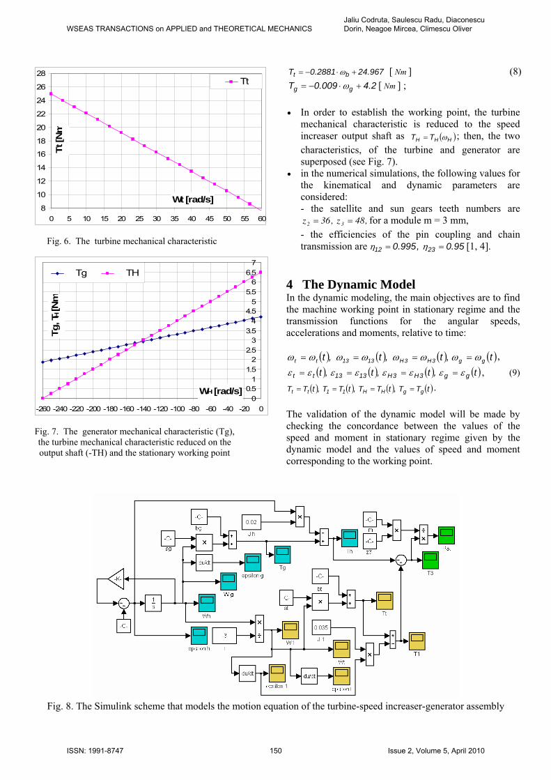
[ ] (8) Nm967.242881.0T bt +⋅−= ω
8
10
12
14
16
18
20
22
24
26
28
0 5 10 15 20 25 30 35 40 45 50 55 60
Wt [rad/s]
Tt [N
m
Tt [ ] ; 2.4009.0T gg +⋅−= ω Nm
• In order to establish the working point, the turbine
mechanical characteristic is reduced to the speed increaser output shaft as ( )HHH TT ω= ; then, the two characteristics, of the turbine and generator are superposed (see Fig. 7).
• in the numerical simulations, the following values for the kinematical and dynamic parameters are considered: - the satellite and sun gears teeth numbers are
for a module m = 3 mm, ,48z,36z 32 == - the efficiencies of the pin coupling and chain
transmission areFig. 6. The turbine mechanical characteristic [1, 4]. 95.0,995.0 2312 == ηη
00.5
11.5
22.5
33.5
44.5
55.5
66.5
7
-260 -240 -220 -200 -180 -160 -140 -120 -100 -80 -60 -40 -20 0
WH [rad/s]
Tg, T
H [N
m
Tg TH 4 The Dynamic Model In the dynamic modeling, the main objectives are to find the machine working point in stationary regime and the transmission functions for the angular speeds, accelerations and moments, relative to time:
( ) ( ) ( ) ( )t,t,t,t gg3H3H1313tt ωωωωωωωω ==== ,( ) ( ) ( ) ( )t,t,t,t gg3H3H1313tt εεεεεεεε ==== , (9)
( ) ( ) ( ) (tTT,tTT,tTT,tTT ggHH11tt = )=== . The validation of the dynamic model will be made by checking the concordance between the values of the speed and moment in stationary regime given by the dynamic model and the values of speed and moment corresponding to the working point.
Fig. 7. The generator mechanical characteristic (Tg), the turbine mechanical characteristic reduced on the output shaft (-TH) and the stationary working point
Fig. 8. The Simulink scheme that models the motion equation of the turbine-speed increaser-generator assembly
WSEAS TRANSACTIONS on APPLIED and THEORETICAL MECHANICSJaliu Codruta, Saulescu Radu, Diaconescu Dorin, Neagoe Mircea, Climescu Oliver
ISSN: 1991-8747 150 Issue 2, Volume 5, April 2010

( ) H01t i1 ωωω −==The working point in the stationary regime is given by
the intersection of the turbine and generator characteristics (see Fig. 7) and is characterized by a speed
For and Ht ωω = , the previous relation becomes:
( )[ ] ( )( ) 0bai1b
i1ai1JJ
gHg0t
20tt
201HH
=−−−++−−−+
ωωε [rad/s] and a moment 6659.143H −=ω 9.2TH =
[Nm].
The dynamic modeling is made by means of Fig. 4, b,c, d, e and f, for the following cases:
By replacing the known parameters into relation (13), the dynamic equation when neglecting friction outcomes:
• The motion equation is modeled by neglecting friction, and • The motion equation is modeled by considering friction.
( )[ ] ( )[ ] ( ) 0bi1bai1ai1JJ g0tg2
0tH2
01HH =−−−+−−−+ ωε (14) 4.1 Case I, friction is neglected
where In this case the Lagrange method is being used [7]: [Nms]; [Nm]; 28818.0at −= 967.24bt = [Nms]; [Nm]; 009.0ag = 2.4bg =
QEE
dtd cc =⎟⎟
⎠
⎞⎜⎜⎝
⎛∂∂
−⎟⎟⎠
⎞⎜⎜⎝
⎛∂∂
ϕω (10)
According to Fig. 4, the kinetic energy Ec and generalized force Q have the following forms, in which dφ/dt = dφH/dt = ωH represents the independent speed:
( )
g3H1t
Hg1tH
2HH
211c
Ti TQ
.T T.Q
;JJ21E
+⋅=
=>+⋅=
⋅+⋅≅
ωωω
ωω
(11)
in which J1, represents the mechanical inertia momentum of the input element 1, respectively JH, for the output element H (see Fig. 4). Deriving Ec relative to time, it is obtained:
0Edtd
;JJ)i1(Edtd
;J.JE
c
HH101H
c
HHH
111
H
c
=⎟⎟⎠
⎞⎜⎜⎝
⎛∂∂
+−=⎟⎟⎠
⎞⎜⎜⎝
⎛∂∂
+∂∂
=∂∂
ϕ
εεω
ωωωω
ω
(12)
From relations (11) and (12) it results:
g3H1tHH101 TiTJJ)i1( +⋅=+− εε (13)
( ) ( ) g0tHH101 Ti1TJJi1 +−=+− εε
( ) H0H3141 i1i εεε −=⋅=
( )[ ] ( ) g0tH2
01H Ti1TJi1J +−=+−ε
tttt baT += ω , gggg baT += ω
( )[ ] ( )( ) ggg0tttH2
01H bai1baJi1J ++−+=+− ωωε
( )[ ] ( )( ) 0bai1b
i1ai1JJ
ggg0t
0tt2
01HH
=−−−++−−−+
ωωε
02.0JH = [ ]; [ ] and
2Kgm 2Kgm035.0J1 =
. 3333.0i1 0 =− After numerical replacements, the following motion equation results:
(15) 012225.402302.0023889.0 HH =+⋅+⋅ ωε 4.1 Case II, friction is considered In this case, according to Fig. 4,b, c, d and e, the following system of equations can be written using the Newton-Euler method:
(16) ;0TTT 3H1 =++
;0TiT H3H1
3H11 =+⋅⋅ η
;0TiT 3001 =+⋅⋅ η ;TTJ 1m11 −=ε .TTJ HbHH −=ε
The following relation is obtained through successive replacements:
( )[ ] ( ) 0Ti1Ti1JJ g3H10t
3H1
201HH =−−−⋅−+ ηηε
By taking into account friction, the equation used for modeling the machine dynamic system is obtained:
( )[ ] ( )[ ]( ) .0b.i1t
a.i1a.i1JJ
g3H10b
g3H1
20tH
3H1
201HH
=−−−
−+−−−+
η
ηωηε (17)
After numerical replacements, the following motion equation results:
(18) 0299677.201601.0023037.0 HH =+⋅+⋅ ωε
WSEAS TRANSACTIONS on APPLIED and THEORETICAL MECHANICSJaliu Codruta, Saulescu Radu, Diaconescu Dorin, Neagoe Mircea, Climescu Oliver
ISSN: 1991-8747 151 Issue 2, Volume 5, April 2010
a) b)
c) d)
e) f)
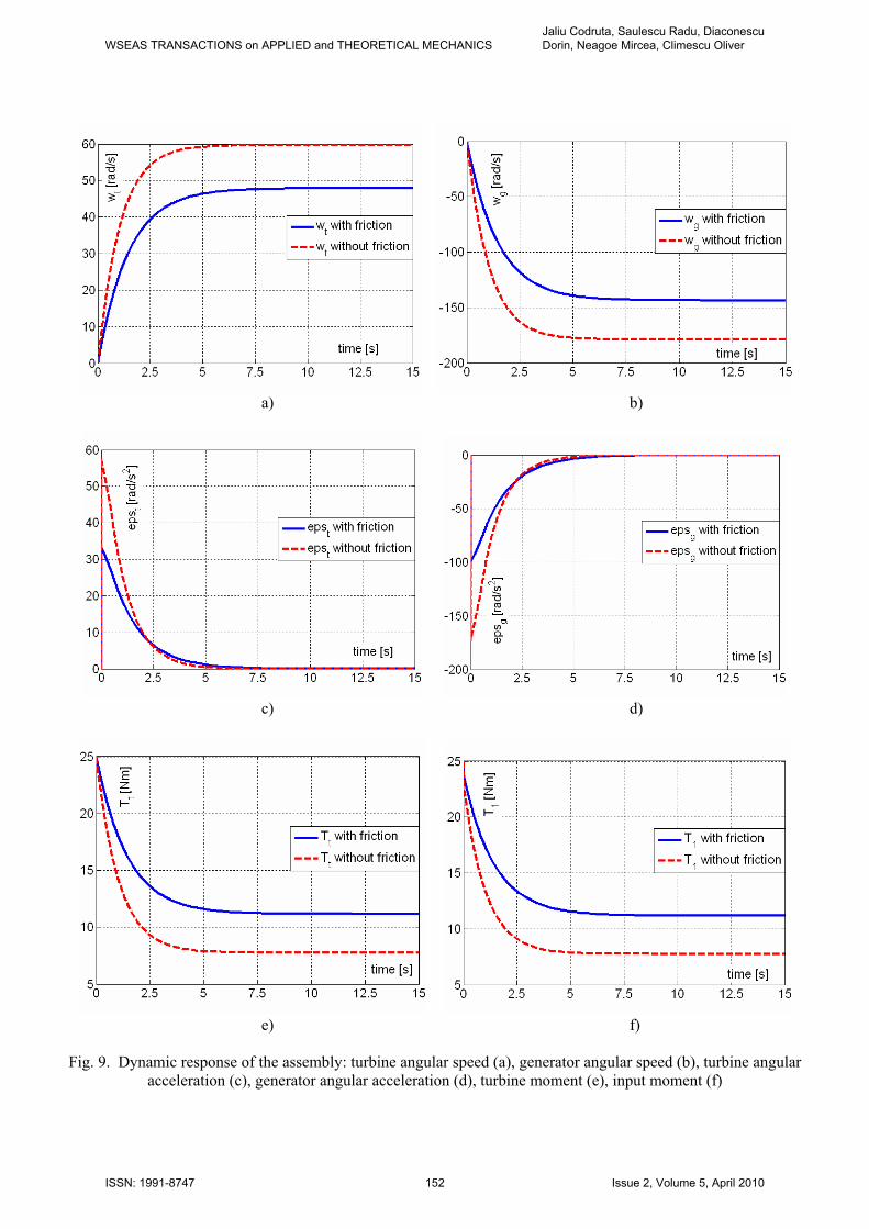
Fig. 9. Dynamic response of the assembly: turbine angular speed (a), generator angular speed (b), turbine angular
acceleration (c), generator angular acceleration (d), turbine moment (e), input moment (f)
WSEAS TRANSACTIONS on APPLIED and THEORETICAL MECHANICSJaliu Codruta, Saulescu Radu, Diaconescu Dorin, Neagoe Mircea, Climescu Oliver
ISSN: 1991-8747 152 Issue 2, Volume 5, April 2010

g) h)
i) j)
Fig. 9. Dynamic response of the assembly: output moment (g), generator moment (h), moment on the sun gear 3 (i), and
force on chain (j). Relation (18) represents the Turgo assembly motion equation in the case of considering friction. It can be easily observed that relation (15) is a particular case of relation (17). 5 Numerical Simulations The values of the output and input angular speeds in stationary regime ( ) are obtained from relations (15) and (18):
0H =ε
- when friction is neglected: ,69191.59;078.179 1H =−= ωω [rad/s]
- when friction is considered: .88816.47;6659.143 1H =−= ωω [rad/s]
The Simulink scheme that models the motion equation of the turbine - planetary speed increaser – generator
assembly is presented in Fig. 8. The machine dynamic response, which consists of the speeds, accelerations and moments as functions of time, for the turbine, speed increaser and electric generator are depicted in the Fig. 9. The variations of the increaser input and output speeds and accelerations are not represented as they coincide to the speeds and accelerations of the turbine and generator, respectively. The forces that act on the chain, P2, P3 and P3’ (Fig. 4,e) are given by the following relation, which is valid when neglecting the chain inertia:
;zm
TdT
r2
TPP
33
3
3
3
3
3
33 ⋅===≅ ′
where m3 = m = 3 mm is the gears’ module. For the model validation, the working point values are compared to the simulation results; it can be observed that the values of speed and moment in the stationary
WSEAS TRANSACTIONS on APPLIED and THEORETICAL MECHANICSJaliu Codruta, Saulescu Radu, Diaconescu Dorin, Neagoe Mircea, Climescu Oliver
ISSN: 1991-8747 153 Issue 2, Volume 5, April 2010

regime on the increaser output shaft, H (Fig. 9, b and g) coincide to the values obtained from Fig. 7. The results of the dynamic modeling are promising a good functioning of the small hydropower plant in real conditions. 6 Conclusions 1) Based on the measurements of water discharge and head performed on some of the rivers from Romanian mountain region, it was decided to design a small hydropower plant to be implemented on a river near Brasov. Taking into account the hydrological parameters, a Turgo turbine assembly was purchased to be installed on the river. 2) The parameters of the turbine and generator were established based on the measurements made on experimental stands; the results highlighted the fact that the turbine performances are improving for lower values of the angular speed, while the generator has better performances at higher speeds. This behavior justifies the use of a speed increaser between the turbine and the generator, which has to increase 3 times the turbine speed.
3) The authors proposed several innovative variants of speed increasers [7, 8, 9, 10, 11], which were comparatively analyzed. The speed increaser to be placed between the turbine and the generator in this application is an innovative solution proposed by the authors, and it is subject to certification. The concept of the speed increaser consists in a planetary chain transmission and a pin coupling (Fig. 2) [9].
4) In certain conditions, the considered transmission can function in two constructive situations: z3<z2 and z3>z2, the first one having higher values of the efficiency and a smaller overall dimension, while the second allows an easier dynamic equilibration. Based on the requirements of radial dimensions and dynamic equilibration, a planetary speed increaser with teeth was chosen as optimal for the considered application.
48z,36z 32 ==
5) The analyzed planetary chain transmission increases the input speed 3 times and decreases the input moment 2.9 times when neglecting friction, and 2.58 times, when considering friction.
6) The same ratios are maintained not only in stationary regime but also at system startup, except that when considering friction when the input moment of the speed increaser is higher; however, in both cases, the input
moment of the speed increaser is smaller than the turbine startup moment and the output moment of the speed increaser is greater than the generator moment, the difference between them being due to inertial effects.
7) The theoretical aspects, from which the dynamic response was obtained are presented in the paper; the mechanical momentums of inertia were computed and the turbine and generator mechanical characteristic were established based on experiments.
8) A simplified dynamic model was used, its differences versus the real dynamic response being acceptable. In the dynamic modeling, the considered inertia mechanical momentums (see Fig. 4) have as an input element 1, the turbine rotor, the input shaft and part of the chain, while for the output element H - the output shaft, generator rotor and the inertial effect of the satellite and of part of the chain, considered as a concentrated mass.
9) The numerical simulations highlight the fact that the small hydropower plant consisting of turbine-speed increaser-generator starts practically in about 8 s, after which enters in the stationary regime.
10) The working point (the speeds and moments) in the stationary regime of the assembly consisting of the Turgo turbine - speed increaser - electric generator was established using the mechanical characteristics of the turbine and generator, superposed on the output shaft. The values were validated by the results of the simulation for the dynamic response using Matlab-Simulink software.
11) The dynamic model is useful in the design of the control system for the small hydro stations and wind turbines. The system control program can be established by considering certain environmental conditions/seasons.
12) Based on the dynamic modeling, the authors will accomplish the design, manufacturing and testing of the speed increaser for an off-grid hydropower station in the framework of a research project. The tests have to validate the theoretical model in real conditions. 7 Acknowledgements The authors will accomplish the design, manufacturing and testing of the speed increaser for stand-alone hydropower stations in the framework of the research project “Innovative mechatronic systems for micro hydros, meant to the efficient exploitation of hydrological potential from off-grid sites”, ID_140. The
WSEAS TRANSACTIONS on APPLIED and THEORETICAL MECHANICSJaliu Codruta, Saulescu Radu, Diaconescu Dorin, Neagoe Mircea, Climescu Oliver
ISSN: 1991-8747 154 Issue 2, Volume 5, April 2010

preparation and publishing of this paper were possible with the financial support of this research project. 8 CORRESPONDING ADDRESS Professor dr. eng. Codruta Jaliu Transilvania University of Brasov, Product Design and Robotics Department Eroilor 29, 500036 Brasov, Romania Phone/Fax: +40 268 472496, E-mail: [email protected] References: [1] American Chain Association, Standard Handbook of
Chains: Chains for Power Transmission and Material Handling, 2nd Edition, Dekker Mechanical Engineering. 2005.
[2] Chereches, T., Sava, AC. Some aspects regarding the using of the dynamics arrays in the numerical simulation of the hydraulic and pneumatic devices, Proc. Of the 6th IASME/WSEAS International Conference on Fluid Mechanics and Aerodynamics FMA’08, pp. 264-268, Aug. 20-22, 2008, Rhodes, Greece.
[3] Cristea, L. The Improvement of Performances in Automatic Dimensional Inspection for Bearing Production, an Important Way to Quality Assurance in Mechanical Engineering, Proceedings of the 8th international conference on instrumentation, measurement, circuits and systems ( IMCAS 09 ). Hangzhou, China: WSEAS, 2009. ISSN 1790-5117, ISBN 978-960-474-076-5, p 91-95.
[4] Diaconescu, D., Products Conceptual Design (Romanian), Transilvania University Publishing House, Brasov, 2005
[5] Harvey, A., Micro-hydro design manual, TDG Publishing House, 2005.
[6] Jaberg, H. Numerical methods for Fluid Dynamical Simulation of Hydro Power Plants. Proc. of 3rd WSEAS International Conference on Energy Planning, Energy Saving, Environmental Education, 3rd WSEAS RES 2009/3rd WSEAS WWAI 2009, pp. 399-413, July 1-3, 2009, Tenerife, Spain.
[7] Jaliu, C., Diaconescu, D.V., Neagoe, M. and Săulescu R., Dynamic features of speed increasers from mechatronic wind and hydro systems, Proc. of EUCOMES 08, 2nd European Conf. on Mechanism Science, pp. 355-373, September 2008, Springer Publishing House, Cassino, Italy, 2008.
[8] Jaliu, C., Diaconescu, D., Neagoe, M., Săulescu, R., Vătăşescu, M. Conceptual synthesis of speed increasers for renewable energy systems. The 10th IFToMM International Symposium on Science of Mechanisms and Machines, Braşov, SYROM 2009, September 12-15, pp. 171-183, 2009, ISBN: 978-90-481-3521-9, SpringerLink.
[9] Jaliu, C., Săulescu, R., Diaconescu, D. and Neagoe, M. Conceptual design of a chain speed increaser for small hydropower stations. Proceedings of the ASME 2009 International Design Engineering Technical Conferences & Computers and Information in Engineering Conference, IDETC/CIE 2009, 30.08 – 2.09, 2009, San Diego, California, USA, CD Proceedings, ISBN: 987-0-7918-3856-3.
[10] Neagoe, M. et al., A Conceptual Design Application Based On A Generalized Algorithm. The 19th International DAAAM Symposium. pp. 0953-0956, Trnava, Slovakia, 2008.
[11] Neagoe, M., Diaconescu, D.V., Jaliu, C., Pascale, L., Săulescu, R. and Siscă, S., On a New Cycloid Planetary Gear used to Fit Mechatronic Systems of RES, OPTIM 2008. Proc. of the 11th Int. Conf. on Optimization of Electrical and Electronic Equipment. Vol. II-B. Renewable Energy Conversion and Control, pp. 439-449, Braşov, Romania, May 2008, IEEE Catalogue 08EX1996, 2008.
[12]Sopian, K., Razak, JA. Pico Hydro: clean power from small streams, Proc. of 3rd WSEAS International Conference on
Energy Planning, Energy Saving, Environmental Education, 3rd WSEAS RES 2009/3 WSEAS WWAI 2009, pp. 414-419, July 1-3, 2009, Tenerife, Spain.
[13] Von Schon, H.A.E.C., Hydro-Electric Practice - A Practical Manual of The Development of Water, Its Conversion To Electric Energy, And Its Distant Transmission, France Press, 2007.
WSEAS TRANSACTIONS on APPLIED and THEORETICAL MECHANICSJaliu Codruta, Saulescu Radu, Diaconescu Dorin, Neagoe Mircea, Climescu Oliver
ISSN: 1991-8747 155 Issue 2, Volume 5, April 2010