ON THE DAMPING OF A PIEZOELECTRIC TRUSS -...
15
ON THE DAMPING OF A PIEZOELECTRIC TRUSS Andre Preumont Active Structures Laboratory, Universit´ e Libre de Bruxelles CP. 165-42, 50 Av. F.D. Roosevelt, B-1050 Brussels, Belgium [email protected] Abstract This paper re-examines the classical problem of active and passive da- mping of a piezoelectric truss. The active damping strategy is the so- called IFF (Integral Force Feedback) which has guaranteed stability; both voltage control and charge (current) control implementations are examined; they are compared to resistive shunting. It is shown that in all three cases, the closed-loop eigenvalues follow a root-locus; closed form analytical formulas are given for the poles and zeros and the max- imum modal damping. It is shown that the performances are controlled by two parameters: the modal fraction of strain energy νi in the ac- tive strut and the electromechanical coupling coefficient k. The paper also briefly addresses the inductive shunting, for which a new parameter comes in: the tuning ratio ωe/ωi between the electrical circuit and the mechanical vibration. Due to space limitations, this paper includes only a small part of the sectional lecture at the 21 st ICTAM. 1. Introduction The active damping of a truss with piezoelectric struts has been largely motivated by producing large, lightweight spacecrafts with im- proved dynamic stability; this classical problem has received a lot of attention over the past 15 years and very effective solutions have been proposed (e.g.[1]). One of them known as Integral Force Feedback (IFF) is based on a collocated force sensor and has guaranteed stability [2]. Traditionally, the piezoelectric actuators have been controlled with a voltage amplifier; this is known to lead to substantial hysteresis caused by the ferroelectric behavior of the material, which requires an external sensor and closed-loop control for precision engineering applications. On the contrary, charge control allows to achieve a nearly linear relationship between the driving electrical value and the free actuator extension (e.g. Mechanics of 21st Century - ICTAM04 Proceedings
Transcript of ON THE DAMPING OF A PIEZOELECTRIC TRUSS -...

ON THE DAMPING
OF A PIEZOELECTRIC TRUSS
Andre PreumontActive Structures Laboratory, Universite Libre de Bruxelles
CP. 165-42, 50 Av. F.D. Roosevelt, B-1050 Brussels, Belgium
Abstract This paper re-examines the classical problem of active and passive da-mping of a piezoelectric truss. The active damping strategy is the so-called IFF (Integral Force Feedback) which has guaranteed stability;both voltage control and charge (current) control implementations areexamined; they are compared to resistive shunting. It is shown that inall three cases, the closed-loop eigenvalues follow a root-locus; closedform analytical formulas are given for the poles and zeros and the max-imum modal damping. It is shown that the performances are controlledby two parameters: the modal fraction of strain energy νi in the ac-tive strut and the electromechanical coupling coefficient k. The paperalso briefly addresses the inductive shunting, for which a new parametercomes in: the tuning ratio ωe/ωi between the electrical circuit and themechanical vibration. Due to space limitations, this paper includes onlya small part of the sectional lecture at the 21st ICTAM.
1. Introduction
The active damping of a truss with piezoelectric struts has beenlargely motivated by producing large, lightweight spacecrafts with im-proved dynamic stability; this classical problem has received a lot ofattention over the past 15 years and very effective solutions have beenproposed (e.g.[1]). One of them known as Integral Force Feedback (IFF)is based on a collocated force sensor and has guaranteed stability [2].
Traditionally, the piezoelectric actuators have been controlled witha voltage amplifier; this is known to lead to substantial hysteresis causedby the ferroelectric behavior of the material, which requires an externalsensor and closed-loop control for precision engineering applications. Onthe contrary, charge control allows to achieve a nearly linear relationshipbetween the driving electrical value and the free actuator extension (e.g.
Mechanics of 21st Century - ICTAM04 Proceedings

2 ICTAM04
[3]). One of the purposes of this paper is to re-examine the theory of theIFF when it is implemented with a current amplifier (charge control).
For space applications, because of the inherent constraints of thelaunch loads, the space environment, and the impossibility of in-orbitmaintenance, there is a strong motivation to reduce or eliminate thepower electronics associated to the piezoelectric actuators as well as thecomplex electronics associated to sensing (particularly in the sub-micronrange where the sensor sensitivity becomes an issue). This has moti-vated the use of passive electrical networks as damping mechanisms [4],[5], [6]. The efficiency of such a damping mechanism depends very muchon the ability to transform mechanical (strain) energy into electricalenergy, measured by the electromechanical coupling factor, and recentimprovements have led to piezoelectric materials with coupling factors ofk33 = 0.7 and more (0.9 ∼ 0.95 is advertised for PMN-PT single cristal),making them a very attractive option for damping trusses. The secondpurpose of this paper is to compare the passive and the active options.They are presented in a very similar formalism and closed-loop resultsare presented, which allow a direct evaluation of the performances interms of two physical parameters: the modal fraction of strain energy νi
in the piezoelectric strut and the electromechanical coupling coefficient
k. Due to space limitations, the discussion is restricted to SISO systems,but most of the extensions for decentralized MIMO control apply here(some of them are discussed in [2]).
Consider the constitutive equations of a one-dimensional piezoelectricmaterial:
DS
=
[
εT d33
d33 sE
]
ET
, (1)
where the standard IEEE notations have been used. If one assumes con-stant strain, stress and electric fields over the actuator, the constitutiveequation can be integrated over the volume of the actuator. With thenotations of Fig. 1, one gets
Q∆
=
[
C nd33
nd33 1/Ka
]
Vf
, (2)
where Q = DAn is the total electric charge, ∆ = Sl is the total ex-tension, f = AT is the total force and V is the total voltage appliedto the piezo (E = nV/l). In Eq. (2), C = εT An2/l is the capacitanceof the piezo, Ka = A/(sEl) is the stiffness of the piezoelectric strut un-der short-circuited conditions (V = 0). Alternatively, using the current
Mechanics of 21st Century - ICTAM04 Proceedings

On the damping of a piezoelectric truss 3
Cross section: A
Thickness : t
# of disks in the stack : n
l=nt
Electric charge :
Capacitance :
C = n2"A=l
Q = nAD
Free piezoelectric expansion:Voltage driven:
Charge driven:
î = d33nV
î = d33nCQ
E=V/ t
Electrode
t
Figure 1. Piezoelectric linear actuator.
I instead of Q, Eq. (2) can be written
I∆
=
[
sC snd33
nd33 1/Ka
]
Vf
, (3)
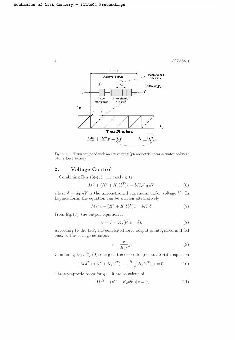
where s is the Laplace variable.Consider the truss structure of Fig. 2, provided with an active strut
consisting of a piezoelectric linear actuator co-linear with a force sensor;the total force in the strut is f . Assuming that the system is undamped,the dynamics of the truss is governed by
Mx + K∗x = bf, (4)
where K∗ is the stiffness matrix with the active strut removed (Fig. 2)and b is the influence vector of the active strut in the global coordinatesystem (the non-zero components of b are the direction cosines of theactive strut in the structure). To make things simpler, but without lossof generality, we will assume that the active strut is massless, so thatthe mass matrix M is the same, with and without the active strut. Notethat the total extension of the active strut can be expressed in terms ofthe global structural displacements as
∆ = bT x, (5)
where bT is the transposed of the influence vector appearing in the pre-vious equation.
Mechanics of 21st Century - ICTAM04 Proceedings
4 ICTAM04
Figure 2. Truss equipped with an active strut (piezoelectric linear actuator co-linearwith a force sensor).
2. Voltage Control
Combining Eqs. (3)-(5), one easily gets
Mx + (K∗ + KabbT )x = bKad33 nV, (6)
where δ = d33nV is the unconstrained expansion under voltage V . InLaplace form, the equation can be written alternatively
Ms2x + (K∗ + KabbT )x = bKaδ. (7)
From Eq. (3), the output equation is
y = f = Ka(bT x − δ). (8)
According to the IFF, the collocated force output is integrated and fedback to the voltage actuator:
δ =g
Kasy. (9)
Combining Eqs. (7)-(9), one gets the closed-loop characteristic equation
[Ms2 + (K∗ + KabbT ) −
g
s + g(Kabb
T )]x = 0. (10)
The asymptotic roots for g → 0 are solutions of
[Ms2 + (K∗ + KabbT )]x = 0, (11)
Mechanics of 21st Century - ICTAM04 Proceedings

On the damping of a piezoelectric truss 5
which corresponds to the global truss when the electrodes of the ac-tive strut are short-circuited, while for g → ∞ (open-loop zeros), theeigenvalue problem is reduced to
[Ms2 + K∗]x = 0, (12)
which corresponds to the situation where the axial contribution of theactive strut has been removed.
3. Charge Control
Upon inverting Eq. (3) and using the fact that
k2 = d2
33/(sEεT ) = n2d2
33Ka/C,
one gets
Vf
=Ka
sC(1 − k2)
[
1/Ka −snd33
−nd33 sC
]
I∆
. (13)
Combining the second of these equations with Eq. (4), one gets
Mx +
[
K∗ + bbT Ka
1 − k2
]
x = b
[
Ka
1 − k2
]
· d33nI
sC. (14)
From the second Eq. (13), we note that d33nI/(sC) is the unconstrainedexpansion (f = 0) under the electric charge Q = I/s, that we willdenote again by δ. As compared to Eq. (7) of the previous section,Eq. (14) shows that the piezoelectric strut behaves with an increasedstiffness Ka/(1 − k2), which is the strut stiffness under open electrodesconditions (I = 0). Also from Eq. (13), the output equation reads:
y = f =Ka
1 − k2(bT x − δ). (15)
As in the previous section, we introduce the IFF feedback law
δ =(1 − k2)g
Kasy, (16)
(same as Eq. (9), except for the stiffness of the piezoelectric strut). Com-bining Eqs. (14)-(16), one gets the closed-loop characteristic equation:
[
Ms2 +
(
K∗ +Ka
1 − k2bbT
)
−g
s + g
Ka
1 − k2bbT
]
x = 0, (17)
Mechanics of 21st Century - ICTAM04 Proceedings

6 ICTAM04
identical to Eq. (10) except that the open electrode stiffness Ka/(1−k2)has been substituted to the short-circuited stiffness Ka. The asymptoticroots for g → 0 (open-loop poles) are solutions of
[
Ms2 +
(
K∗ +Ka
1 − k2bbT
)]
x = 0, (18)
which corresponds to the global truss when the electrodes of the activestrut are open, while for g → ∞, the eigenvalue problem is reduced to
[Ms2 + K∗]x = 0, (19)
which corresponds to the situation where the active strut has been re-moved. Thus, the open-loop zeros are identical to those for the voltagecontrol case.
4. Passive Shunting
Figure 3(a) shows the electrical analog of the piezo. If a passive shuntof admittance YSH is connected in parallel with the piezo (Fig. 3(b)),the constitutive equations of the active strut become
I∆
=
[
sC + YSH snd33
nd33 1/Ka
]
Vf
. (20)
This equation applies to active as well as passive control. In the formercase, the control input is I or V ; in the latter case, I = 0 and V can beeliminated from Eq. (20). Combining with Eq. (4) and (5), one finds:
[
Ms2 +(
K∗ + KabbT)
+k2Kabb
T
(1 − k2) + YSH/sC
]
x = 0. (21)
Ip
sC YSH
V
I
sC
I
V
Ip = snd33f
(b)(a)
Figure 3. (a) Electrical analog of the piezo. (b) with a passive shunt.
Mechanics of 21st Century - ICTAM04 Proceedings

On the damping of a piezoelectric truss 7
Note that we recover the expected asymptotic forms for YSH = 0 (openelectrodes)
[
Ms2 +
(
K∗ +Ka
1 − k2bbT
)]
x = 0 (22)
and, for YSH = ∞ (short-circuited electrodes):[
Ms2 +(
K∗ + KabbT)]
x = 0. (23)
In the special case of a resistive shunting,
YSH
sC=
1
sRC. (24)
5. Modal Damping
We now consider the closed-loop characteristic equation in modal co-ordinates and derive analytical results for the modal damping, for allthree cases considered in the previous sections, namely IFF with voltagecontrol, IFF with charge (current) control and resistive shunting. In allcases, the results take the form of a root locus with striking similarities.
IFF, Voltage Control
The development follows closely that of [2]; transforming in modalcoordinates according to x = Φz, assuming normal modes normalizedaccording to ΦT MΦ = I; the mode shapes are solution of the eigenvalueproblem Eq. (11). Denoting
ΦT (K∗ + KabbT )Φ = ω2 = diag(ω2
i ), (25)
where ωi are the natural frequencies of the truss with short-circuitedelectrodes, Eq. (10) is rewritten
[
Is2 + ω2 −g
s + gΦT (Kabb
T )Φ
]
z = 0. (26)
The matrix ΦT (KabbT )Φ is in general fully populated; assuming that it
is diagonally dominant, and neglecting the off-diagonal terms, it can berewritten
ΦT (KabbT )Φ ≃ diag(νiω
2
i ) (27)
where
νi =φT
i(Kabb
T )φi
φTi(K∗ + KabbT )φi
, (28)
is the fraction of modal strain energy in the active strut when the trussvibrates according to mode i. According to the assumption Eq. (27), the
Mechanics of 21st Century - ICTAM04 Proceedings

8 ICTAM04
open-loop frequency response function (FRF) between the unconstrainedexpansion δ and the output force y of the collocated sensor can be written([2], p.61)
G(ω) =y
δ= Ka
[
n∑
i=1
νi
1 − ω2/ω2
i
− 1
]
, (29)
where the sum extends to all the modes. Thus, the fractions of modalstrain energy νi constitute the residues of the modal expansion of theopen-loop FRF (Fig. 4). The fact that they are all positive guaranteesalternating poles and zeros, as one would expect from a collocated (anddual) actuator/sensor configuration.
G(!)
z1 z2 z3
!1 !2 !3
P
i=1
n
÷ià 1 P
i=m+1
n
÷ià 1
Poles
Zeros
Figure 4. Open loop FRF G(ω) of the active truss.
It follows also from the assumption Eq. (27) that the eigenvalue prob-lem Eq. (26) reduces to a set of uncoupled equations
s2 + ω2
i −g
s + gνiω
2
i = 0. (30)
Denoting
z2
i = ω2
i (1 − νi), (31)
Eq. (30) can be transformed into
1 + gs2 + z2
i
s(s2 + ω2
i)
= 0, (32)
Mechanics of 21st Century - ICTAM04 Proceedings

On the damping of a piezoelectric truss 9
which shows that every mode follows a root locus with poles at ±jωi
and at s = 0, and zeros at ±jzi (Fig. 5). Comparing with Eq. (12), thelatter are readily identified as the natural frequencies of the structurewhen the axial contribution of the active strut has been removed. Themaximum modal damping is given by
ξmaxi =
ωi − zi
2zi
(33)
and it is achieved for g = ωi
√
ωi/zi [2].
IFF
ømaxi =2z i
!iàz i
ømaxi!i
zi
Figure 5. Root locus of the IFF, voltage control (only half of the locus is shown).
IFF, Charge Control
If we consider the charge implementation of the IFF (with a currentamplifier), the closed-loop characteristic equation is given by Eq. (17).Transforming in modal coordinates as in the previous section, but usingthe normal modes of the truss with open electrodes, solutions of theeigenvalue problem (Eq. (18)), the natural frequencies and the fractionof modal strain energy are defined respectively by
ΦT (K∗ +Ka
1 − k2bbT )Φ = Ω2 = diag(Ω2
i ), (34)
νi =φT
i( Ka
1−k2 bbT )φi
φTi(K∗ + Ka
1−k2 bbT )φi
. (35)
Following the same development as in the previous section, one findsthat the closed-loop poles follow the root locus
Mechanics of 21st Century - ICTAM04 Proceedings

10 ICTAM04
1 + gs2 + z2
i
s(s2 + Ω2
i)
= 0, (36)
which is similar to that of Fig. 5, except that the poles at ±jΩi cor-respond in this case to the natural frequencies of the truss with openelectrodes; the zeros are identical to those of the previous case.
Resistive Shunting
For resistive shunting, the characteristic equation is given by Eq. (21)with YSH = 1/R; denoting RC = and transforming in modal coordi-nates as in the previous sections, one finds that every mode follow thecharacteristic equation
s2 + ω2
i +k2νiω
2
i
1 − k2 + 1/s= 0 (37)
which can be rewritten in a root locus form
1 +s2 + ω2
i
(1 − k2)s[s2 + ω2
i+ k2
1−k2 νiω2
i]= 0 (38)
where 1/(1− k2) plays the role of the gain in a classical root locus. Atthe denominator, one recognizes that the poles are located at the naturalfrequencies of the truss with open electrodes
Ω2
i ≃ ω2
i
(
1 +k2
1 − k2νi
)
, (39)
while the zeros are at ±jωi, the natural frequencies of the truss withshort-circuited electrodes. Figure 6 and Table 1 summarize the results ofthe three control configurations. Column 4 of Table 1 gives an analyticalexpression for the maximum achievable modal damping based on thepoles and zeros; the approximation given in column 5 is based on
ξmaxi =
ωi − zi
2zi
≃ω2
i− z2
i
4z2
i
. (40)
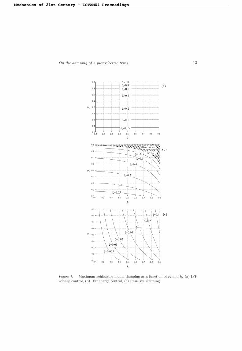
The influence of the fraction of modal strain energy νi and the electro-mechanical coupling factor k appear much more clearly in the approxi-mate results. Figure 7 shows a chart of the maximum achievable modaldamping for the three control strategies, as a function of νi and k (basedon the exact solution); the contour lines correspond to constant modaldamping. Note that:
(i) For the IFF with voltage control, the maximum damping is inde-pendent of the electromechanical coupling factor.
Mechanics of 21st Century - ICTAM04 Proceedings

On the damping of a piezoelectric truss 11
Figure 6. Root locus plots corresponding to various control configurations.
(ii) The IFF with charge control gives always better performances thanwith voltage control; the advantage increases with k.
(iii) Significant modal damping with resistive shunting can only beachieved when the electromechanical coupling factor is large (sayk ≥ 0.7); the availability of materials with such properties wasactually part of the motivations for this study.
6. Inductive Shunting
Inductive shunting was first proposed in [4]; if the piezoelectric trans-ducer is shunted on a RL circuit such that the natural frequency of theelectrical circuit is tuned on the natural frequency of one mode, the sys-tem behaves like a tuned mass damper [6]. The extension to multiplemodes has been addressed in [7], where the use of a set of parallel shuntsis suggested; other methods are reviewed in [8]. This section is by nomeans comprehensive but, once again, the closed-loop poles for induc-tive shunting are presented in the form of a root locus where the majorstructural (νi), material (k), and electrical (ωe/ωi) parameters appearexplicitly.
The characteristic equation for an arbitrary passive shunting is givenby Eq. (21). Upon transforming in modal coordinates, with the sameassumptions as in the previous section, one finds that the characteristicequation for mode i reads:
Mechanics of 21st Century - ICTAM04 Proceedings

12
ICTA
M04
Table 1. Open-loop poles and zeros and maximum achievable modal damping
Type of Control Open-loop poles Open-loop zeros ξi (exact solution) ξi (approximate)
±jzi
IFF (voltage control) ±jωi ≃ ±jωi
√1 − νi
√1−νi−(1−νi)
2(1−νi)νi
4(1−νi)
±jΩi
IFF (charge control) ±jωi
√
1 + k2νi
1−k2 ±jzi
√
1+k2νi1−k2−
√1−νi
2√
1−νi
νi4(1−νi)(1−k2)
Resistive shunting ±jΩi ±jωi
√
1+k2νi1−k2−1
2k2νi
4(1−k2)
Mechanics of 21st Century - ICTAM04 Proceedings
On the damping of a piezoelectric truss 13
(a)
(c)
(b)
÷i
k
x=0.05
x=0.1
x=0.2
x=0.4
x=0.6
x=0.8x=1.0
k
÷i
x=0.05
x=0.1
x=0.2
x=0.4
x=0.6
x=0.8 x=1.0
Over critical
÷i
k
x=0.05
x=0.005
x=0.01
x=0.02
x=0.1
x=0.2
x=0.4
Figure 7. Maximum achievable modal damping as a function of νi and k. (a) IFFvoltage control, (b) IFF charge control, (c) Resistive shunting.
Mechanics of 21st Century - ICTAM04 Proceedings

14 ICTAM04
s2 + ω2
i +k2νiω
2
i
1 − k2 + YSH/sC= 0. (41)
If the passive shunt consists of a RL circuit, YSH = (Ls + R)−1 and
YSH
sC=
1
LCs2 + RCs. (42)
Upon introducing the electrical natural frequency ω2e = (LC)−1 and the
fraction of critical damping ξe such that 2ξeωe = R/L, one gets
YSH
sC=
1
s2/ω2e + 2ξes/ωe
(43)
and the characteristic Eq. (41) becomes
s2 + ω2
i +k2νiω
2
i(s2 + 2ξeωes)
(1 − k2)(s2 + 2ξeωes) + ω2e
= 0. (44)
This equation can, once again, be rearranged in the form of a rootlocus
1 + 2ξeωe ·s(s2 + Ω2
i)
(s2 + p21)(s2 + p2
2)
= 0, (45)
in which 2ξeωe plays the role of the gain. Ωi is the natural frequency withopen electrodes (±jΩi are indeed the asymptotic poles when the resistorR becomes very large), and p2
1and p2
2are solutions of the characteristic
equation
s4
ω4
i
+s2
ω2
i
[
1 +k2νi
1 − k2+
ω2e
ω2
i
1
1 − k2
]
+ω2
e
ω2
i
1
1 − k2= 0 (46)
which, in addition to νi and k, also depends on the tuning ratio ωe/ωi
between the electrical circuit and the mechanical vibration. The upperhalf of the root locus consists of two loops whose size depends on thevalues of the parameters; the depth of the smaller loop in the left halfplane tends to be bigger when the tuning ratio is close to 1.
7. Conclusions
Various active and passive ways of damping a piezoelectric truss havebeen examined; the results have been presented in the common formof a root locus, and analytical formulae have been established for themaximum achievable modal damping. The influence of the modal frac-tion of strain energy νi in the active strut (structural parameter) andthe electromechanical coupling coefficient k (material parameter) on theperformance has been pointed out.
Mechanics of 21st Century - ICTAM04 Proceedings

On the damping of a piezoelectric truss 15
Acknowledgments
This study was partly supported by ESA (SSPA project).
References
[1] A. Preumont, J.P. Dufour, C. Malekian, Active damping by a local force feedbackwith piezoelectric actuators, AIAA J. of Guidance, Vol.15, No 2, 390-395, March-April, 1992.
[2] A. Preumont, Vibration Control of Active Structures, An Introduction, (2nd Edi-tion), Kluwer, 2002.
[3] C. Dorlemann, P. Muss, M. Schugt, R. Uhlenbrock, New high speed current con-trolled amplifier for PZT multilayer stack actuators, ACTUATOR-2002, Bremen,June, 2002.
[4] R.L. Forward, Electronic damping of vibrations in optical structures, Journal of
Applied Optics, Vol.18, 690-697, March, 1979.
[5] N.W. Hagood, A. von Flotow, Damping of structural vibrations with piezoelec-tric materials and passive electrical networks, Journal of Sound and Vibration,Vol.146, No 2, 243-268, 1991.
[6] N.W. Hagood, E.F. Crawley, Experimental investigation of passive enhancementof damping for space structures,AIAA J. of Guidance, Vol.14, No 6, 1100-1109,Nov.Dec. 1991.
[7] J.J. Hollkamp, Multimodal passive vibration suppression with piezoelectric ma-terials and resonant shunts, J. Intell. Material Syst. Structures, Vol.5, Jan.1994.
[8] S.O.R. Moheimani, A survey of recent innovations in vibration damping andcontrol using shunted piezoelectric transducers, IEEE Transactions on Control
Systems Technology, Vol.11, No 4, 482-494, July 2003.
Mechanics of 21st Century - ICTAM04 Proceedings
<< back