On the Axisymmetric Counterflow Flame Simulations: Is ...
23
Combust. Sci. Technol., 187: 37–59, 2015 Copyright © Taylor & Francis Group, LLC ISSN: 0010-2202 print / 1563-521X online DOI: 10.1080/00102202.2014.972503 ON THE AXISYMMETRIC COUNTERFLOW FLAME SIMULATIONS: IS THERE AN OPTIMAL NOZZLE DIAMETER AND SEPARATION DISTANCE TO APPLY QUASI ONE-DIMENSIONAL THEORY? R. F. Johnson, A. C. VanDine, G. L. Esposito, and H. K. Chelliah Department of Mechanical and Aerospace Engineering, University of Virginia, Charlottesville, Virginia, USA Two-dimensional axisymmetric numerical analysis of counterflow flames was employed to better understand the applicability of the quasi one-dimensional theory of Seshadri and Williams to flames produced by small diameter convergent nozzles. The computational domain considered included the convergent sections of two opposed nozzles as well as the surrounding inert annular co-flows. For computational efficiency, the fuel-oxidizer sys- tem of diluted hydrogen versus air in non-premixed flame mode, with a detailed chemical kinetic model and mixture-averaged transport property description, was considered. With an increase of nozzle diameter from 6.5 mm to larger values (with plug flow velocity pro- files at the nozzle exit), the influence of the radial terms on eigenvalue and scalar variables has been compared. Error metric on nozzle diameter effects is presented with comparison to typical experimental measurement uncertainties. The analysis also showed that, for nozzle separation distances below the free-floating limit, the self-similar function in quasi one- dimensional formulation can be preserved by specifying radial velocity boundary conditions, as long as the radial gradients are negligible. Keywords: Counterflow flames; Nozzle diameter; Nozzle separation distance; Quasi one-dimensional theory INTRODUCTION The theory that reduces the two-dimensional axisymmetric counterflow or opposed- jet flame configuration to a quasi one-dimensional (1D) formulation is well established and widely used throughout the combustion community (Kee et al., 1989, 2003; Seshadri and Williams, 1978; Smooke et al., 1991). The key assumptions in the derivation of quasi 1D theory are (i) description of the radial flow velocity via a self-similarity function, v r = rU (z), and (ii) zero radial gradients of all scalar variables along the axis of symmetry. A direct consequence of approximations (i) and (ii) is that the radial pressure-gradient, = (1/r) (∂ p/∂ r), is treated as a constant eigenvalue along the axis of symmetry. The Received 4 August 2014; revised 29 September 2014; accepted 30 September 2014. Published as part of the Special Issue in Honor of Professor Forman A. Williams on the Occasion of His 80th Birthday with Guest Editors Chung K. Law and Vigor Yang. Address correspondence to H. K. Chelliah, Dept. of Mechanical and Aerospace Engineering, University of Virginia, 122 Engineers Way, Charlottesville, VA 22904, USA. E-mail: [email protected] Color versions of one or more of the figures in the article can be found online at www.tandfonline.com/gcst. 37 Downloaded by [University of Virginia, Charlottesville], [H. K. Chelliah] at 04:09 08 June 2015
Transcript of On the Axisymmetric Counterflow Flame Simulations: Is ...

Combust. Sci. Technol., 187: 37–59, 2015Copyright © Taylor & Francis Group, LLCISSN: 0010-2202 print / 1563-521X onlineDOI: 10.1080/00102202.2014.972503
ON THE AXISYMMETRIC COUNTERFLOW FLAMESIMULATIONS: IS THERE AN OPTIMAL NOZZLEDIAMETER AND SEPARATION DISTANCE TO APPLYQUASI ONE-DIMENSIONAL THEORY?
R. F. Johnson, A. C. VanDine, G. L. Esposito,and H. K. Chelliah
Department of Mechanical and Aerospace Engineering, University of Virginia,Charlottesville, Virginia, USA
Two-dimensional axisymmetric numerical analysis of counterflow flames was employed tobetter understand the applicability of the quasi one-dimensional theory of Seshadri andWilliams to flames produced by small diameter convergent nozzles. The computationaldomain considered included the convergent sections of two opposed nozzles as well as thesurrounding inert annular co-flows. For computational efficiency, the fuel-oxidizer sys-tem of diluted hydrogen versus air in non-premixed flame mode, with a detailed chemicalkinetic model and mixture-averaged transport property description, was considered. Withan increase of nozzle diameter from 6.5 mm to larger values (with plug flow velocity pro-files at the nozzle exit), the influence of the radial terms on eigenvalue and scalar variableshas been compared. Error metric on nozzle diameter effects is presented with comparison totypical experimental measurement uncertainties. The analysis also showed that, for nozzleseparation distances below the free-floating limit, the self-similar function in quasi one-dimensional formulation can be preserved by specifying radial velocity boundary conditions,as long as the radial gradients are negligible.
Keywords: Counterflow flames; Nozzle diameter; Nozzle separation distance; Quasi one-dimensional theory
INTRODUCTION
The theory that reduces the two-dimensional axisymmetric counterflow or opposed-jet flame configuration to a quasi one-dimensional (1D) formulation is well establishedand widely used throughout the combustion community (Kee et al., 1989, 2003; Seshadriand Williams, 1978; Smooke et al., 1991). The key assumptions in the derivation of quasi1D theory are (i) description of the radial flow velocity via a self-similarity function, vr =rU (z), and (ii) zero radial gradients of all scalar variables along the axis of symmetry.A direct consequence of approximations (i) and (ii) is that the radial pressure-gradient,� = (1/r) (∂p/∂r), is treated as a constant eigenvalue along the axis of symmetry. The
Received 4 August 2014; revised 29 September 2014; accepted 30 September 2014.Published as part of the Special Issue in Honor of Professor Forman A. Williams on the Occasion of His
80th Birthday with Guest Editors Chung K. Law and Vigor Yang.Address correspondence to H. K. Chelliah, Dept. of Mechanical and Aerospace Engineering, University
of Virginia, 122 Engineers Way, Charlottesville, VA 22904, USA. E-mail: [email protected] versions of one or more of the figures in the article can be found online at www.tandfonline.com/gcst.
37
Dow
nloa
ded
by [
Uni
vers
ity o
f V
irgi
nia,
Cha
rlot
tesv
ille]
, [H
. K. C
helli
ah]
at 0
4:09
08
June
201
5

38 R. F. JOHNSON ET AL.
validity of this theory has been well established by Seshadri and co-workers (Puri andSeshadri, 1986) in experiments using large diameter nozzles with screens (typically of theorder of 25 mm or greater in diameter) to produce a uniform axial velocity profile at thenozzle exits (see Figure 1a), with a nozzle separation distance of about 14 mm.
The above ideal large diameter nozzle counterflow configuration cannot always berealized in experiments. For example, in conducting studies at extreme pressure or strainrate conditions, two-phase flows, or when performing advanced laser-based diagnostics,small diameter nozzles are beneficial and have been explored by many researchers (Mittalet al., 2012; Wu and Law, 1984). The inconsistencies that could arise from applying quasi1D theory of Seshadri and Williams (1978) to small diameter nozzles has been a topicof great interest. Specifically, it is important to quantify the uncertainties introduced inapplying quasi 1D theory to counterflow flames if such data is to be used in chemicalkinetic model optimization or validation investigations.
As first shown by Rolon et al. (1991), experiments with converging nozzles withlarge area ratios (without screens) suffer from nonuniform axial velocities as the nozzleseparation distance is reduced from an ideal separation distance that yielded a plug flowprofile (see Figure 1b). A consequence of such nonideal flow separation distance is that theassumed zero axial velocity gradient in the axial direction at the nozzle exit, ∂vz/∂z = 0(or U (z) = 0 via continuity equation ∂ (ρvz) /∂z = −2ρU (z) with constant density in thecold invicid flow region), is not satisfied in such experiments. A method for correcting thisinconsistent finite U (z) in quasi 1D simulations with nonideal nozzle separation distanceswas first proposed by Chelliah et al. (1991). Subsequent work by Dimotakis and co-workers(Bergthorson et al., 2005, 2011) and by Sarnacki et al. (2012) further highlighted theimportance of proper boundary conditions with nozzle separation distance. In particular,for premixed flames stabilized over a stagnation plate with heat losses, Bergthorson et al.(2005, 2011) have shown that the reacting viscous boundary layer is invariant with the noz-zle separation distance once the nozzle separation distance is in the free-jet regime. It isimportant to note that the quasi 1D theory cannot be applied to freejet regime irrespectiveof the nozzle diameter. In contrast to stagnation flame-plate configuration, counterflow oropposed-jet laminar flames cannot be stabilized at large nozzle separation distances with-out some anchoring mechanism (see Figure 1b). The nozzle separation distance at whichthey are barely anchored is identified as the freely-floating regime, L = LFF (Pellett et al.,1991; Sarnacki et al., 2012). Moreover, Sarnacki et al. (2012) experimentally demonstratedthat, as this ideal nozzle separation distance that yields a plug-flow profile is approached,the flame extinction strain rate defined by the Seshadri and Williams theory (identifiedhere as atheory) agrees with the local extinction strain rate (identified as alocal), within theexperimental uncertainties.
The first 2D numerical investigation on small diameter nozzles in counterflow flameswas performed by Frouzakis et al., (1998) using the axisymmetric configuration. The mainfocus of their investigation was the effect of nozzle exit velocity profiles (i.e., plug versusparabolic flow) on predicted non-premixed flame structure, for a specific nozzle diameter(D = 10 mm) and separation distance (L = 10 mm). In their axisymmetric simulations, thepressure eigenvalue, �, was shown to deviate from the constant value in quasi 1D formula-tion, especially in the cold region where local flow strain rate is quantified. It was reportedthat this deviation reduced as the diameter of the nozzle was doubled, without providingany quantitative information. The study’s main conclusion was that quasi 1D formulationis adequate as long as a uniform velocity or plug flow condition is satisfied at the noz-zle exit, without any explicit recommendation or guidance on preferred L or D to be usedin experiments. In a more recent axisymmetric numerical investigation on twin-premixed
Dow
nloa
ded
by [
Uni
vers
ity o
f V
irgi
nia,
Cha
rlot
tesv
ille]
, [H
. K. C
helli
ah]
at 0
4:09
08
June
201
5

AXISYMMETRIC COUNTERFLOW FLAME SIMULATIONS 39
(a) Nozzle separation distance = L
Mixing layer
FuelAir
Stagnation plane Flame
(b)Nozzle separation distance = L
Free-floating regime (LFF < L)
Mixing layer
FuelAir
Stagnation plane
Flame
Free-jet
(c) nozzle separation distance = L
Free-floating regime (LFF = L)
Mixing layer
FuelAir
Stagnation plane
Flame
Figure 1 Schematic of counterflow diameter and separation distance effects: (a) large nozzle setup (Seshadri typeburner) with plug-flow velocity profile, (b) small diameter nozzles with non-ideal separation distances (L > LFF
with plug flow and free-jet or L < LFF with finite U values), and (c) small nozzles with ideal separation distance(L = LFF).
counterflow flames using 14 mm nozzles, Mittal et al. (2012) have shown that the inclusionof radial heat conduction term in quasi 1D simulations has much greater effect than theeigenvalue departure from a constant value. The main goal of the investigation was to
Dow
nloa
ded
by [
Uni
vers
ity o
f V
irgi
nia,
Cha
rlot
tesv
ille]
, [H
. K. C
helli
ah]
at 0
4:09
08
June
201
5

40 R. F. JOHNSON ET AL.
determine the flame stretch effects on premixed burning velocity. Bouvet et al. (2013) alsoperformed axisymmetric numerical investigations on a premixed flame-plate configurationusing a 7-mm nozzle, including experimental measurement of the velocity field. By consid-ering a nonreacting case with an equivalent L > LFF (i.e., a separation distance greater thanthe free-floating regime where quasi 1D theory does not apply), they came to the conclu-sion that quasi 1D theory fails to represent the stagnation flow-plate configuration. In thereacting case, with an effective nozzle separation distance less than the free-floating regime(L < LFF) due to thermal expansion of the reacting mixing layer, the subtle differences ofthe axial velocity predicted using axisymmetric and quasi 1D formulations also highlightedthe inadequacy of the quasi 1D theory.
None of the aforementioned studies systematically addressed the effects of nozzlediameter on the neglected radial gradients in quasi 1D formulation. As mentioned earlier,Frouzakis et al. (1998) suggested that doubling the nozzle diameter could reduce the eigen-value nonuniformity in the cold region. Furthermore, they stated that the average value ofthe eigenvalue in axisymmetric simulation is close to the constant eigenvalue assumed inquasi 1D simulations; hence, the quasi 1D formulation is acceptable for the small diameternozzle considered. In experiments, Sarnacki et al. (2012) attempted to address the noz-zle diameter effect on counterflow flame extinction limits, however, the two nozzles used(7 mm and 15 mm) were not identical in area contraction ratio leading to two differentboundary layers at the nozzle exits and they failed to draw any meaningful conclusions.Here, by using a consistent nozzle geometry generated by minimization of Görtler vorticityformation (see Bergthorson et al., 2005), the effects of nozzle diameter versus separationdistance on the quasi 1D formulation is analyzed numerically.
In the axisymmetric numerical analysis presented here, the OpenFOAM computa-tional package was used to integrate the governing equations with a Finite Volume Methodsolver, that includes the detailed transport and chemical kinetic models (Jasak et al., 2007).To lower computational cost, diluted hydrogen versus air counterflow non-premixed flamewith a modest extinction strain rate of around 400 s−1 was considered. Such strain rates areclose to the extinction limits of methane-air non-premixed flames and other mildly dilutedhydrocarbon-air extinction limits; hence, these conditions are of great relevance. In addi-tion, in both axisymmetric and quasi 1D simulations, the Soret effects were neglected.Several computational geometries corresponding to Seshadri type and small diameter noz-zle type configurations (see Figure 1) were considered to highlight the differences betweenquasi 1D and full counterflow geometry simulations on flame structure as well as extinctionlimit predictions.
GOVERNING EQUATIONS AND NUMERICAL APPROACH
The reacting Navier–Stokes equations that describe the conservation of mass,momentum, energy, and species of axisymmetric counterflow field are well known (Keeet al., 2003; Williams, 1985), and for brevity, only the essential features are presentedhere. A key difference between the 2D axisymmetric (OpenFOAM) and the quasi 1Dimplementation is that the equations are written in conservative and non-conservativeform, respectively (see the appendix for a complete mathematical formulation). Thetwo conservation equations of importance for the present discussion are the steadystate radial momentum and the energy conservation equations—in 2D axisymmetricimplementation:
Dow
nloa
ded
by [
Uni
vers
ity o
f V
irgi
nia,
Cha
rlot
tesv
ille]
, [H
. K. C
helli
ah]
at 0
4:09
08
June
201
5

AXISYMMETRIC COUNTERFLOW FLAME SIMULATIONS 41
ρv∂vr
∂z+ ρvr
∂vr
∂r= −∂p
∂r+ ∂
∂z
(μ
∂vr
∂z
)+{
∂
∂r
(μ
r
∂vr
∂r
)}︸ ︷︷ ︸
Term1
(1)
∂
∂z(ρvhs) − ∂
∂z
(ρα
∂hs
∂z
)+ ∂
∂z
(N∑
i=1
ρhsi−→V z,i
)
= −N∑
i=1
h0i wi +
{− ∂
∂r(ρvrhs) + ∂
∂r
(ρα
∂hs
∂r
)− ∂
∂r
(N∑
i=1
ρhsi−→V r,i
)}︸ ︷︷ ︸
Term 2
(2)
and in quasi 1D theory implementation with vr = rU (z):
ρv∂U
∂z+ ρU2 = −1
r
∂p
∂r+ ∂
∂z
(μ
∂U
∂z
)(3)
ρv∂hs
∂z− ∂
∂z
(α
∂hs
∂z
)+ ∂
∂z
(N∑
i=1
ρhsi Vz,i
)= −
N∑i=1
h0i wi (4)
In Eqs. (1) and (2), the Term1 and Term2 are the contributions due to radial effects,for example if the flame should experience any radial gradients due to small nozzlediameters.
In the OpenFOAM solver, the 2D axisymmetric conservation equations [Eqs. (A.1)–(A.4)] were integrated using the Finite Volume Method in a segregated manner. The finitevolume terms were calculated using second-order accurate total variation diminishing(TVD) Van–Leer schemes (Hirsch, 2007). For low-speed reacting flows, an iterative processwas implemented to solve for the pressure field as there is no efficient explicit equation forpressure at low Mach numbers. This solver used the pressure implicit splitting of operators(PISO) method (Issa, 1986), which iterates between the solved velocity field and a guessedpressure field until a specified numerical tolerance is met. For the hydrogen-air system con-sidered, the chemical source terms were described using a detailed chemical kinetic modelconsisting of 11 species in 29 reactions, which was extracted from the JetSurf2.0 model(Wang et al., 2011). All transport and thermodynamic quantities were calculated using thesame approach as the Sandia Transport Package (Kee et al., 1986) and thermodynamicdatabase (Kee et al., 1993), respectively, and were integrated into the OpemFOAM solver.To verify the implementation of the OpenFOAM solver, several canonical reacting flowconfigurations were considered and are described in the appendix.
In the quasi 1D implementation, the conservation equations were integrated usingSmooke’s counterflow code (Smooke et al., 1991) as well as the Sandia Oppdif code(Lutz et al., 1997). The same chemical kinetic model parameters as well as the transportcoefficients were implemented for comparisons with the 2D axisymmetric (OpenFOAM)solution.
Dow
nloa
ded
by [
Uni
vers
ity o
f V
irgi
nia,
Cha
rlot
tesv
ille]
, [H
. K. C
helli
ah]
at 0
4:09
08
June
201
5

42 R. F. JOHNSON ET AL.
Computational Domain
For a Seshadri type burner having large diameter nozzles (D = 26 mm), an axisym-metric computational domain having a wedge-shaped mesh (see Figure 2a) with uniformvelocity profiles at fuel and air exit planes was considered (i.e., without nitrogen co-flow),as shown in Figure 2b. For smaller diameter nozzles, a computational domain with simi-lar wedge-shaped mesh but with full details of the converging nozzles with annular inertnitrogen co-flow was considered, as shown in Figure 2c. As mentioned earlier, the fuel andair nozzle shapes considered were similar to those used in experiments by Sarnacki et al.(2012), which were designed to minimize vorticity generation in the convergent section.In order to analyze the small diameter effects, two grids were generated with inner nozzle
Figure 2 Computational domains implemented showing (a) 2D wedge-shape mesh with r and z coordinates,(b) typical solution from large diameter Seshadri type plug-flow burners, and (c) solution from a small diameternozzle type burners.
Dow
nloa
ded
by [
Uni
vers
ity o
f V
irgi
nia,
Cha
rlot
tesv
ille]
, [H
. K. C
helli
ah]
at 0
4:09
08
June
201
5

AXISYMMETRIC COUNTERFLOW FLAME SIMULATIONS 43
diameters of 6.5 and 13 mm. Together with the Seshadri type configuration described above,the nozzle diameter effects were analyzed for D = 6.5, 13, and 26 mm. To address the noz-zle separation distance effects, several computational grids were generated for D = 6.5 mmnozzles (L = 4 and 8 mm) and for D = 13 mm nozzles (L = 5, 9, 13, 16, and 19.5 mm).
Various structured grid refinement strategies were explored depending on the com-plexity of the computational domain. For example, for the Seshadri type burner computa-tional domain (Figure 2b), a uniform grid spacing of 15 µm was used for all the caseswith excellent agreement with the quasi 1D solutions. For more complex small nozzlediameter computational domains, both uniform and stretched grids were considered. In theunstretched regions, a uniform grid spacing of 30 µm was maintained with a maximumaspect ratio of 2.0. To establish grid independence, in the reacting layer the grid was refinedfor several cases to achieve a 15-µm grid spacing and the steady-state solutions confirmedthat the results were in the asymptotic range with only 3 K change in temperature between30 and 15 µm solutions.
Boundary Conditions
Figure 2b shows the computational domain simulated for the Seshadri type burner,while Figure 2c shows the domain for a small diameter nozzle that included the entirety ofthe fuel, air, and co-flow nozzles, mixing region, and outflow region. In the 2D axisymmet-ric simulations, the inflow planes were different depending on the computational geometryconsidered. The boundary conditions imposed at the inflow planes consisted of fixed veloc-ity plug flow, Neumann condition for pressure, fixed ambient temperature (T0 = 300 K),and fixed species mole fractions (diluted hydrogen (XH2 = 0.16) versus air (XO2 = 0.21)).The inclusion of the full nozzle geometry in the small diameter simulations allowed the plugflow upstream velocity to develop into the expected nonuniform velocity profiles at the noz-zle exits. The plug-flow velocities prescribed were varied to explore strain effects on theflame. However, the precise local strain rate specification was difficult due to variation innozzle exit velocity profile depending on the nozzle separation distance and thermal expan-sion. In the small diameter nozzle case, the inert nitrogen co-flow momentum was alwaysmatched with the momentum of the inner jet. This assured that the shear layer formedbetween the inner and the outer streams did not influence the flow divergence. Outflowboundary conditions of the computational domain were similar for all cases and were pre-scribed by fixing far-field pressure nodes and Neumann conditions for all other variables.Nozzle walls and edges were described by no-slip, viscous boundary conditions by settingnormal and tangential velocity components to zero, and all other variables were describedby Neumann conditions at the wall face. Chemical reactions were initiated by imposinga Gaussian temperature profile over a nonreacting diffusion solution and residuals weremonitored to assure convergence for all solutions.
In the quasi 1D flame solutions, the pressure was held constant at the average valuedetermined from axisymmetric simulations and the temperature and species boundaryconditions imposed were the same as those described above in the 2D axisymmetric simula-tions. In addition, the velocity boundary conditions (vz and U) in the quasi 1D formulationwere matched with the OpenFOAM solutions (identified as OF) as described below, forlarge diameter nozzle (Seshadri type burner):
z = ±L
2, vz = (vz)OF , U = 0 (5)
Dow
nloa
ded
by [
Uni
vers
ity o
f V
irgi
nia,
Cha
rlot
tesv
ille]
, [H
. K. C
helli
ah]
at 0
4:09
08
June
201
5
44 R. F. JOHNSON ET AL.
and for small diameter nozzles:
L = LFF : z = ±L
2, vz = (vz)OF , U = 0 (6)
L < LFF : z = ±L
2, vz = (vz)OF , U = UOF �= 0 (7)
L > LFF : quasi one-dimensional theory cannot be applied (8)
RESULTS
Large Diameter Seshadri Type Burner Simulations
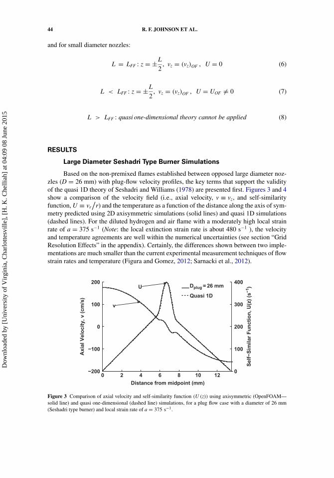
Based on the non-premixed flames established between opposed large diameter noz-zles (D = 26 mm) with plug-flow velocity profiles, the key terms that support the validityof the quasi 1D theory of Seshadri and Williams (1978) are presented first. Figures 3 and 4show a comparison of the velocity field (i.e., axial velocity, v ≡ vz, and self-similarityfunction, U ≡ vr
/r) and the temperature as a function of the distance along the axis of sym-
metry predicted using 2D axisymmetric simulations (solid lines) and quasi 1D simulations(dashed lines). For the diluted hydrogen and air flame with a moderately high local strainrate of a = 375 s−1 (Note: the local extinction strain rate is about 480 s−1 ), the velocityand temperature agreements are well within the numerical uncertainties (see section “GridResolution Effects” in the appendix). Certainly, the differences shown between two imple-mentations are much smaller than the current experimental measurement techniques of flowstrain rates and temperature (Figura and Gomez, 2012; Sarnacki et al., 2012).
0 2 4 8 10 120
100
200
300
400
Distance from midpoint (mm)
Se
lf−
Sim
ila
r F
un
cti
on
, U
(z)
(s−
1)
6−200
−100
0
100
200
Ax
ial
Ve
loc
ity
, v
(c
m/s
)
Dplug = 26 mm
Quasi 1D
v
U
Figure 3 Comparison of axial velocity and self-similarity function (U (z)) using axisymmetric (OpenFOAM—solid line) and quasi one-dimensional (dashed line) simulations, for a plug flow case with a diameter of 26 mm(Seshadri type burner) and local strain rate of a = 375 s−1.
Dow
nloa
ded
by [
Uni
vers
ity o
f V
irgi
nia,
Cha
rlot
tesv
ille]
, [H
. K. C
helli
ah]
at 0
4:09
08
June
201
5
AXISYMMETRIC COUNTERFLOW FLAME SIMULATIONS 45
−6 −4 −2 0 2 4 6200
400
600
800
1000
1200
Distance from Midpoint (mm)
Tem
pera
ture
at
r =
0 (
K)
Dplug = 26 mm
Quasi 1D
−0.05 0 0.05 0.11140
1145
1150
1155
1160
1165
1170
Figure 4 Comparison of flame temperature using axisymmetric (OpenFOAM—solid line) and quasi one-dimensional (dashed line) simulations, for a plug flow case with a diameter of 26 mm (Seshadri type burner)and strain rate of a = 375 s−1.
A key observation from the above results are that (a) the self-similarity function,U(z), agrees well in both cold hydrodynamic region as well as inside the reacting mixinglayer region and (b) the excellent agreement implies that the radial terms included inthe axisymmetric simulation are negligible. One can further evaluate the contribution ofthe radial terms in 2D axisymmetric formulation in comparison to the dominant axialterms. For example, in the radial momentum equation, at steady state, the only term thatis neglected in the quasi 1D formulation is the Term1 identified in Eq. (1). Any finitecontribution of the Term1 can be thought of as the residue in Eq. (3) and will mani-fest as a variation of � in axisymmetric simulations. This residue is identified here asR�. Figure 5 shows a comparison of the eigenvalue, �, calculated from quasi 1D and 2Daxisymmetric simulations, together with all other remaining terms contributing to the radialmomentum equation, Eq. (1). For the present large diameter nozzle simulations, the depar-ture of the eigenvalue from a constant value determined from the quasi 1D is very small(� = − (7.6 ± 0.2) × 10−4 Pa
/m2), especially in the cold hydrodynamic region where the
flow strain rate is typically calculated. In contrast, previous work with small diameter noz-zles have reported comparatively larger departure of the eigenvalue from quasi 1D theory(Bouvet et al., 2013; Frouzakis et al., 1998; Mittal et al., 2012).
Any radial variations in counterflow flames can also influence the solution of energyand species conservation equations, i.e., scalar properties T and Yi. In Eq. (2), Term2 iden-tifies the radial gradient dependencies in energy conservation equation that give rise todifferences between the axisymmetric and the quasi 1D solutions. For the present discus-sion, this residual term is identified as Rh. Figure 6 shows a comparison of all the termsin Eq. (2) evaluated using 2D axisymmetric and quasi 1D solutions, including the residueterm Rh. A very small value of Rh implies that for the present large diameter Seshadritype burner with plug-flow velocity profiles, the radial term in energy equation is negligi-ble and the quasi one-dimensional theory accurately represents the 2D axisymmetric flowfield.
Dow
nloa
ded
by [
Uni
vers
ity o
f V
irgi
nia,
Cha
rlot
tesv
ille]
, [H
. K. C
helli
ah]
at 0
4:09
08
June
201
5

46 R. F. JOHNSON ET AL.
−6 −4 −2 0 2 4 6−10
−5
0
5
10
Distance from Midpoint (mm)
Term
s o
f M
om
en
tum
Eq
uati
on
(P
a/m
2 ×
10
−4)
Λ
ρ v dU/dzρU2
d/dz(μ dU/dz)
Dplug = 26 mm
Quasi 1D
Figure 5 Comparison of the terms in radial momentum equation (including eigenvalue, �) using axisymmetric(OpenFOAM—solid line) and quasi one-dimensional (dashed line) simulations, for a plug flow with a diameterof 26 mm (Seshadri type burner) and strain rate of a = 375 s−1.
−2 −1 0 1 2−5
0
5
Distance from Midpoint (mm)
Te
rms
of
En
erg
y
Eq
ua
tio
n (
Kg
/m/s
3 ×
10
−8) ρ v dhs/dz
Rh
Σi = 1
Nh
iow
i
d/dz((α)d hs/dz)
Dplug = 26 mm
Quasi 1D
Figure 6 Comparison of the terms in the quasi one-dimensional energy equation using axisymmetric(OpenFOAM—solid line) and quasi one-dimensional (dashed line) simulations, for a plug flow with a diame-ter of 26 mm (Seshadri type burner) and strain rate of a = 375 s−1. The residue of axisymmetric solution isidentified as Rh, which is mainly due to the radial heat conduction term.
Nozzle Diameter Effects
While the concept of minimizing radial effects by increasing the nozzle diameter isnot new, the main purpose of the present article is to develop an error metric to quantify theeffect of radial contributions in small diameter counterflow flames, as a function of both thenozzle diameter and the nozzle separation distance. To our knowledge, such a systematicinvestigation has not been reported in the literature, which is now possible due to advancedcomputational capabilities available. For two nozzle diameters of D = 13 and 6.5 mm witha nozzle separation distance of L = 4 mm, Figures 7–10 show comparisons of the velocity
Dow
nloa
ded
by [
Uni
vers
ity o
f V
irgi
nia,
Cha
rlot
tesv
ille]
, [H
. K. C
helli
ah]
at 0
4:09
08
June
201
5

AXISYMMETRIC COUNTERFLOW FLAME SIMULATIONS 47
−1.5 −1 −0.5 0 0.5 1 1.5−60
−40
−20
0
20
40
60
U
v
Ax
ial
Ve
loc
ity
, v
(c
m/s
)
Distance from Midpoint (mm)
0
100
200
300
400
500
Se
lf S
imil
ar
Fu
nc
tio
n,
U(z
) (s
−1)Dnozzle = 13 mm
Dnozzle = 6.5 mm
Figure 7 Comparison of axial velocity and self-similarity function (U (z)) using axisymmetric (OpenFOAM—solid line) and quasi one-dimensional (dashed line) simulations, for (i) nozzle flow with diameter of 13 mm andstrain rate of a = 268 s−1, and (ii) nozzle flow with diameter of 6.5 mm and strain rate of a = 354 s−1.
−1.5 −1 −0.5 0 0.5 1 1.5
400
600
800
1000
1200
Distance from Midpoint (mm)
Te
mp
era
ture
at
r =
0 (
K)
Dnozzle = 13 mm
Dnozzle = 6.5 mm
−0.2 0 0.2 0.4 0.6
1110
1120
1130
1140
1150
1160
1170
1180
1190
1200
1210
1220
1230
1240
Figure 8 Comparison of flame temperature using axisymmetric (OpenFOAM—solid line) and quasi one-dimensional (dashed line) simulations, for (i) nozzle flow with diameter of 13 mm and strain rate of a = 268 s−1
and (ii) nozzle flow with diameter of 6.5 mm and strain rate of a = 354 s−1.
field and temperature, terms contributing to the radial momentum equation and energy con-servation equation, respectively, predicted using the 2D axisymmetric simulations and quasi1D simulations. Since L < LFF with finite U values at the nozzle exit planes, in quasi 1Dsimulations, both vz,±L/2 and U±L/2 values from 2D simulations are imposed. Alternatively,if these boundary conditions are available from experiments, for example, from PIV mea-surements (Sarnacki et al., 2012), they can be imposed in quasi 1D simulations. While thelocal strain rates are different for the two nozzle diameters considered (a = 268 s−1 forD = 13 mm and a = 354 s−1 for D = 6.5 mm), a small but noticeable difference of theflame structure between the 2D axisymmetric and quasi 1D simulations is observed. In par-ticular, the residual term Rh in energy equation (see Figure 11) shows an increased departureas the nozzle diameter is reduced from 13 mm to 6.5 mm. A quantitative comparison of
Dow
nloa
ded
by [
Uni
vers
ity o
f V
irgi
nia,
Cha
rlot
tesv
ille]
, [H
. K. C
helli
ah]
at 0
4:09
08
June
201
5

48 R. F. JOHNSON ET AL.
−2 −1 0 1 2−8
−6
−4
−2
0
2
4
6
Distance from Midpoint (mm)
Term
s o
f M
om
en
tum
Eq
uati
on
(P
a/m
2 ×
10
−4)
Λ
ρ v dU/dz
ρU2
d/dz(μ dU/dz)
Dnozzle = 13 mm
Dnozzle = 6.5 mm
Figure 9 Comparison of the terms in radial momentum equation (including eigenvalue, �) using axisymmetric(OpenFOAM—solid line) and quasi one-dimensional (dashed line) simulations, for (i) nozzle flow with diameterof 13 mm and strain rate of a = 268 s−1 and (ii) nozzle flow with diameter of 6.5 mm and strain rate of a =354 s−1.
–1.5 –1 –0.5 0 0.5 1 1.5–4
–2
0
2
4
Distance from Midpoint (mm)
Te
rms
of
En
erg
y E
qu
ati
on
(Kg
/m/s
3 ×
10
−8)
ρ v dhs/dz
Rh
Σi = 1
Nh
iow
i
d/dz((α)d hs/dz)
Dnozzle = 13 mm
Dnozzle = 6.5 mm
Figure 10 Comparison of the terms in the quasi one-dimensional energy equation using axisymmetric(OpenFOAM—solid line) and quasi one-dimensional (dashed line) simulations, for (i) nozzle flow with diam-eter of 13 mm and strain rate of a = 268 s−1 and (ii) nozzle flow with diameter of 13 mm and strain rate ofa = 354 s−1. The residue of axisymmetric solution is identified as Rh, which is mainly due to the radial heatconduction term.
diameter effects on �, Rh, and U is presented in the section, “Metric for Quantification ofRadial Effects.”
For the smaller diameter nozzles (D = 6.5 mm), the temperature comparisons shownin Figure 8 indicate 46 K difference in peak flame temperature between the 2D axisym-metric and quasi 1D simulations. This difference is certainly greater than any numericaleffects discussed in the appendix (of the order of 10 K). In contrast, for the larger diame-ter nozzle (D = 13 mm), difference in predicted peak temperature is 20 K. Since accurate
Dow
nloa
ded
by [
Uni
vers
ity o
f V
irgi
nia,
Cha
rlot
tesv
ille]
, [H
. K. C
helli
ah]
at 0
4:09
08
June
201
5

AXISYMMETRIC COUNTERFLOW FLAME SIMULATIONS 49
−1.5 −1 −0.5 0 0.5 1 1.5−0.08
−0.06
−0.04
−0.02
0
0.02
0.04
Distance from Midpoint (mm)
Resid
ual T
erm
of
En
erg
y E
qu
ati
on
,
Rh (
Kg
/m/s
3 ×
10
−8)
Dnozzle = 13 mm
Dnozzle = 6.5 mm
Figure 11 Comparison of the residue term only in the energy equation (Rh), for (i) nozzle flow with diameter of13 mm and strain rate of a = 268 s−1 and (ii) nozzle flow with diameter of 13 mm and strain rate of a = 354 s−1.
estimation of flame temperature is critical for chemical kinetic model validation, it is impor-tant to understand the origin of these temperature variations. The first clue is that, for theD = 6.5 mm nozzle, the deviation of self-similar function U between the two simulationsis significant irrespective of the specification of the exact axial velocity and U values atthe boundaries (see Figure 7). Examination of the terms contributing to the radial momen-tum equation (Figure 9) shows that while most terms are of the same order, the eigenvaluespread is significantly large for the D = 6.5 mm case in comparison to the D = 13 mm noz-zles. Secondly, consistent with the analysis by Mittal et al. (2012), the residue of the energyequation is dominated by the radial heat conduction term and increases with decreasing thenozzle diameter (see Figure 11).
Nozzle Separation Distance Effects
Unlike in the Seshadri type burner with screens, in small diameter nozzle experimentsit is impossible to determine a priori the ideal nozzle separation distance where U = 0 at theboundaries. This is because of the variability of the mixing layer thickness, Lmixing, whichdepends on the thermal expansion associated with the overall heat release and the imposedflow strain rates (or the Reynolds number). Thus, in quasi 1D simulation of small diam-eter counterflow experiments with an arbitrarily selected nozzle separation distance, thefinite U values at the boundaries must be either measured from experiments, or calculatedas in present 2D simulations. The fundamental assumption in such quasi 1D calculationswith imposed finite U values is that the radial gradients are negligible irrespective of thenozzle diameter. To explore the applicability of this assumption, 2D axisymmetric calcu-lations were carried out for several different nozzle separation distances using both nozzlediameters considered above. For brevity, only the smaller diameter nozzles’ results are pre-sented here. Figures 12–15 show a comparison between the 2D axisymmetric results andthe quasi 1D simulations for L = 4 and 8 mm. Qualitatively, smaller separation distancesimulations with imposed finite U values seem to yield results in closer agreement with the2D axisymmetric simulations.
Dow
nloa
ded
by [
Uni
vers
ity o
f V
irgi
nia,
Cha
rlot
tesv
ille]
, [H
. K. C
helli
ah]
at 0
4:09
08
June
201
5

50 R. F. JOHNSON ET AL.
−3 −2 −1 0 1 2 3−100
−50
0
50
100
UvA
xia
l V
elo
cit
y,
v (
cm
/s)
Distance from Midpoint (mm)
0
100
200
300
400
500
Se
lf S
imil
ar
Fu
nc
tio
n,
U(z
) (s
−1)L = 8 mm
L = 4 mm
Figure 12 Comparison of axial velocity and self-similarity function (U(z)) using axisymmetric (OpenFOAM—solid line) and quasi one-dimensional (dashed line) simulations, for two separation distances using 6.5 mm nozzles(i) L = 8 mm and strain rate of a = 290 s−1 and (ii) L = 4 mm and strain rate of a = 354 s−1.
−4 −2 0 2 4
400
600
800
1000
1200
Distance from Midpoint (mm)
Te
mp
era
ture
at
r =
0 (
K)
L = 8 mm
L = 4 mm
−0.2 0 0.2 0.41140
1150
1160
1170
1180
1190
1200
1210
1220
Figure 13 Comparison of temperature using axisymmetric (OpenFOAM—solid line) and quasi one-dimensional(dashed line) simulations, for two separation distances using 6.5 mm nozzles (i) L = 8 mm and strain rate of a =290 s−1 and (ii) L = 4 mm and strain rate of a = 354 s−1.
Metric for Quantification of Radial Effects
Instead of making qualitative comparisons between 2D axisymmetric and quasi 1Dsimulations, a quantitative estimate of the neglected radial terms can be evaluated bysuitably defined error metric, for example the L2-norm given by:
L2 (φi) =√∑Nc
j=1 (φi)2j
Nc(9)
where φ2i = (�2D − �1D)2, R2
h, or (U2D − U1D)2 are summed over computational cells,Nc, from j = 1, . . . , Nc along the axis of symmetry. Figures 16 and 17 show comparisons
Dow
nloa
ded
by [
Uni
vers
ity o
f V
irgi
nia,
Cha
rlot
tesv
ille]
, [H
. K. C
helli
ah]
at 0
4:09
08
June
201
5

AXISYMMETRIC COUNTERFLOW FLAME SIMULATIONS 51
−4 −2 0 2 4−6
−4
−2
0
2
4
Distance from Midpoint (mm)
Λ
ρ v dU/dz
ρU2
d/dz(μ dU/dz)
L = 8 mm
L = 4 mm
Te
rms
of
Mo
me
ntu
m E
qu
ati
on
(Pa
/m2 ×
10
−4)
Figure 14 Comparison of the terms in radial momentum equation (including eigenvalue, �) using axisymmetric(OpenFOAM—solid line) and quasi one-dimensional (dashed line) simulations, for two separation distances using6.5 mm nozzles (i) L = 8 mm and strain rate of a = 290 s−1 and (ii) L = 4 mm and strain rate of a = 354 s−1.
−2 −1 0 1 2−4
−2
0
2
4
Distance from Midpoint (mm)
Te
rms
of
En
erg
y E
qu
ati
on
(Kg
/m/s
3 ×
10
−8)
ρ v dhs/dz
Rh
Σi = 1
Nh
i
ow
i
d/dz((α)d hs/dz)
L = 4 mm
L = 8 mm
Figure 15 Comparison of the terms in quasi one-dimensional energy equation using axisymmetric(OpenFOAM—solid line) and quasi one-dimensional (dashed line) simulations, for two separation distances using6.5 mm nozzles (i) L = 8 mm and strain rate of a = 290 s−1 and (ii) L = 4 mm and strain rate of a = 354 s−1.The residue of axisymmetric solution is identified as Rh, which is mainly due to the radial heat conduction term.
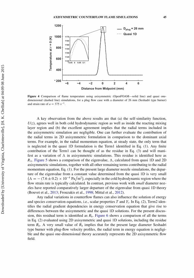
of such a metric as a function of the nozzle diameter and nozzle separation distance,respectively.
The large diameter Seshadri type burners clearly yield the lowest L2-norm as seenfrom Figure 16. However, it may be useful to correlate the error metric to typical measure-ment uncertainties and explore the existence of an optimal nozzle diameter and separationdistance or a range in applying quasi 1D theory. To address this question, the eigen-value variance shown in Figure 9 is first correlated with the local strain rate variations.For example, in the case of diluted hydrogen and air flame considered, for D = 13 mmcase, the predicted eigenvalue variation between −2.86 × 10⁻⁴ to −3.4 × 10⁻⁴ Pa/m2
corresponds to a local strain rate variation of 267 s−1 to 275 s−1 and to a peak flame
Dow
nloa
ded
by [
Uni
vers
ity o
f V
irgi
nia,
Cha
rlot
tesv
ille]
, [H
. K. C
helli
ah]
at 0
4:09
08
June
201
5
52 R. F. JOHNSON ET AL.
6.5 13 26 300
0.5
1
Diameter, D (mm)
L2/(
L2) D
= 6
.5m
m
L2 Rh
L2 Λ
L2 U(z)
Figure 16 Comparison of the L2-norm evaluated based on �, Rh, and U as a function of the nozzle diameter, fornozzle separation distance of L = 4 mm. Note: L2-norm values are normalized by those at D = 6.5 mm.
5 9 13 16 19.5 260
0.5
1
1.5
Separation Distance, L (mm)
L2 Rh
L2 Λ
L2 U(z)
L2/(
L2) L
= 5
mm
Figure 17 Comparison of the L2-norm evaluated based on �, Rh, and U as a function of the nozzle separationdistance, for nozzle diameter of D = 13 mm. Note: L2-norm values are normalized by those at L = 5 mm.
temperature variation of 1228 K to 1240 K. These variations are well within the currentmeasurement uncertainties (Figura and Gomez, 2012; Sarnacki et al., 2012). Even forthe smaller diameter nozzle considered, the eigenvalue variation between −5.75 × 10⁻⁴
to −7.0 × 10⁻⁴ Pa/
m2 yields very modest local strain rate variations between 328 s−1 to339 s−1 and peak flame temperature variations of 1167 K to 1185 K, again well within theexperimental measurement uncertainties, but greater than the numerical uncertainties.
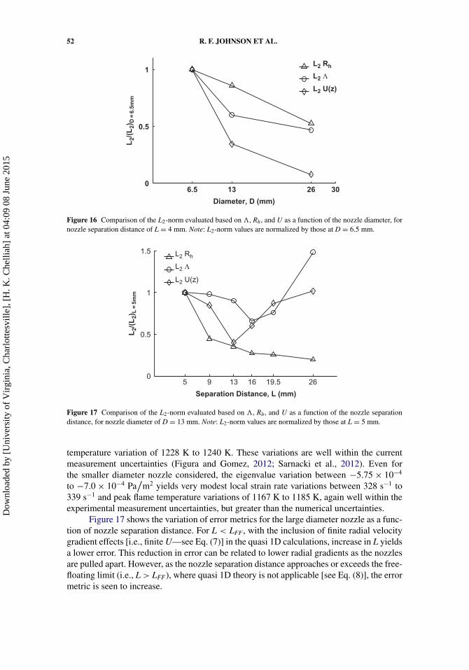
Figure 17 shows the variation of error metrics for the large diameter nozzle as a func-tion of nozzle separation distance. For L < LFF, with the inclusion of finite radial velocitygradient effects [i.e., finite U—see Eq. (7)] in the quasi 1D calculations, increase in L yieldsa lower error. This reduction in error can be related to lower radial gradients as the nozzlesare pulled apart. However, as the nozzle separation distance approaches or exceeds the free-floating limit (i.e., L > LFF), where quasi 1D theory is not applicable [see Eq. (8)], the errormetric is seen to increase.
Dow
nloa
ded
by [
Uni
vers
ity o
f V
irgi
nia,
Cha
rlot
tesv
ille]
, [H
. K. C
helli
ah]
at 0
4:09
08
June
201
5

AXISYMMETRIC COUNTERFLOW FLAME SIMULATIONS 53
While this investigation considered only a limited range of flame strain rate varia-tions (slightly away from flame extinction limit), based on the above discussion, it maybe reasonable to conclude that as long as finite U values are imposed at the bound-aries, small diameter nozzle experiments with nozzle diameters of the order of 12 mm orgreater can be used with quasi 1D simulations. Furthermore, for 13-mm diameter nozzles1 < L
/D < LFF
/D is seen to yield the lowest departure between 2D and quasi 1D solu-
tions. Whether this finding can be generalized to any small diameter nozzles is not clear.One essential requirement in applying the quasi 1D theory is that the nozzle separation dis-tance must lie between the free-floating distance and the mixing layer thickness. Violationof the latter will lead to heat losses at the nozzles.
CONCLUSIONS
2D axisymmetric counterflow reacting flow simulations were performed to investi-gate the applicability of quasi 1D theory of Seshadri and Williams to small diameter, largearea-ratio converging nozzles. Analysis was also performed with large diameter nozzleswith plug flow boundary conditions (Seshadri type burners) to demonstrate the negligibleeffects of the radial terms in conservation equations. When applied to smaller diame-ter converging nozzles, the influence of non-zero contributions of radial terms on radialmomentum and energy conservation equations were explicitly evaluated. Based on a nor-malized error metric, and the diluted hydrogen versus air non-premixed flames considered,it was suggested that nozzle diameters greater than 12 mm will yield errors less than numer-ical uncertainties and certainly well below current experimental uncertainties. With regardto nozzle separation distance, analysis was performed for distances greater than the mixinglayer distance and lower than the free-floating regime distance. It was shown that, as longas radial effects are small, specification of finite values for the self-similar function at theboundaries in quasi 1D simulations can predict the flow strain rates and flame temperaturewithin numerical or experimental uncertainties.
While the verification of the 2D OpenFOAM numerical solver was performed byconsidering chemical source term integrations, premixed flame structure solutions, andnon-premixed flame extinction limit predictions using simpler Seshadri type burner con-figuration, further work is needed to establish the nozzle-based extinction limit predictions.Once completed, the solver developed with parallel computing capabilities can providea valuable tool for future multi-dimensional laminar flame investigations with detailedchemical kinetic models.
ACKNOWLEDGMENT
Harsha Chelliah gratefully acknowledges stimulating discussions with Professor FormanWilliams, which led to the work described in this article.
FUNDING
The authors would like to acknowledge the Air-Force High-Energy Laser JointTechnology Office (HEL-JTO) for funding, under the HEL JTO MRI Program (AFOSR-BAA-2010-2). Ryan Johnson was supported by the Department of Defense (DoD) throughthe National Defense Science & Engineering Graduate Fellowship (NDSEG) Program andthe Virginia Space Grant Consortium (VSGC) Graduate Fellowship Program.
Dow
nloa
ded
by [
Uni
vers
ity o
f V
irgi
nia,
Cha
rlot
tesv
ille]
, [H
. K. C
helli
ah]
at 0
4:09
08
June
201
5

54 R. F. JOHNSON ET AL.
REFERENCES
Bergthorson, J.M., Salusbury, S.D., and Dimotakis, P.E. 2011. Experiments and modelling ofpremixed laminar stagnation flame hydrodynamics. J. Fluid Mech., 681, 340–369.
Bergthorson, J.M., Sone, K., Mattner, T.W., Dimotakis, P.E., Goodwin, D.G., and Meiron, D.I. 2005.Impinging laminar jets at moderate reynolds numbers and separation distances. Phys. Rev. E, 72,066307-1–066307-12.
Bouvet, N., Davidenko, D., Chauveau, C., Pillier, L., and Yoon, Y. 2013. On the simulation of laminarstrained flames in stagnation flows: 1D and 2D approaches versus experiments. Combust. Flame,161(2), 438–452
Chelliah, H.K., Law, C.K., Ueda, T., Smooke, M.D., and Williams, F.A. 1991. An experimental andtheoretical investigation of flow-field, dilution and pressure effects on the extinction conditionof methane/oxygen/nitrogen diffusion flames. Proc. Combust. Inst., 23, 503–511.
Cuoci, A., Frassoldati, A., Faravelli, T., and Ranzi, E. 2013. A computational tool for the detailedkinetic modeling of laminar flames: Application to C2H4 / CH4 coflow flames. Combust. Flame,160, 870–886.
Figura, L., and Gomez, A. 2012. Laminar counterflow steady diffusion flames under high pressureconditions. Combust. Flame, 159(1), 142–150.
Frouzakis, C.E., Lee, J., Tomboulides, A.G., and Boulouchos, K. 1998. Two-dimensional directnumerical simulation of opposed-jet hydrogen-air diffusion flame. Proc. Combust. Inst., 27,571–577.
Hirsch, C. 2007. Numerical Computation of Internal and External Flows, second ed., Butterworth-Heinemann, Oxford.
Issa, R.I. 1986. The computation of compressible and incompressible recirculating flows by a non-iterative implicit scheme. J. Comput. Phys., 62, 66–82.
Jasak, H., Jemcov, A., and Tukovic, Z. 2007. Openfoam: A c++ library for complex physics simu-lations. Presented at the International Workshop on Coupled Methods in Numerical Dynamics,IUC, Dubrovnik, Croatia, September 19–21.
Kee, R.J., Coltrin, M.E., and Glarborg, P. 2003. Chemically Reacting Flow, John Wiley and Sons,Hoboken, NJ.
Kee, R.J., Grcar, J.F., Smooke, M.D., Miller, J.A., and Meeks, E. 1998. Premix: A fortran programfor modeling steady laminar one-dimensional premixed flames. Technical Report SAND 1998,Sandia Report.
Kee, R.J., Miller, J.A., Evans, G.H., and Dixon-Lewis, G. 1989. A computational model of the struc-ture and extinction of strained, opposed flow, premixed methane-air flames. Proc. Combust. Inst.22(1), 1479–1494.
Kee, R.J., Miller, J.A., and Warnatz, J. 1986. A fortran computer code package for the evaluation ofgas-phase multicomponent transport properties. Technical Report SAND86, Sandia Report.
Kee, R.J., Rupley, F.M., and Miller, J.A. 1993. Chemkin-ii: A fortran chemical kinetics package forthe analysis of gas phase chemical kinetics. Technical Report SAND89-8009B, Sandia Report.
Lutz, A.E., Kee, R.J., Grcar, J.F., and Rupley, F.M. 1997. Oppdif: A fortran program for computingopposed-flow diffusion flames. Technical Report SAND 1997, Sandia Report.
Lutz, A., Kee, R.J., and Miller, J.A. 1987. Senkin: A fortran program for predicting homogeneous gasphase chemical kinetics with sensitivity analysis. Technical Report SAND87, Sandia NationalLaboratories Report.
Mittal, V., Pitsch, H., and Egolfopoulos, F. 2012. Assessment of counterflow to measure laminarburning velocities using direct numerical simulations. Combust. Theor. Modell., 16(3), 419–433.
Oevermann, M., Gerber, S., and Behrendt, F. 2009. Euler-Lagrange/DEM simulation of woodgasification in a bubbling fluidized bed reactor. Particuology 4, 307–316.
Pellett, G.L., Northam, G.B., and Wilson, L.G. 1991. Counterflow diffusion flames of hydrogen,and hydrogen plus methane, ethylene, propane, and silane vs. air. AIAA 1991–0370. AIAAAerospace Sciences Meeting, Washington, DC, January 7–10.
Dow
nloa
ded
by [
Uni
vers
ity o
f V
irgi
nia,
Cha
rlot
tesv
ille]
, [H
. K. C
helli
ah]
at 0
4:09
08
June
201
5

AXISYMMETRIC COUNTERFLOW FLAME SIMULATIONS 55
Puri, I.K., and Seshadri, K. 1986. Extinction of diffusion flames burning diluted methane and dilutedpropane in diluted air. Combust. Flame, 65, 137–150.
Reinelt, D., Laurs, A., and Adomeit, G. 1998. Ignition and combustion of a packed bed in a stag-nation point flow Part II: Heterogeneous and homogeneous reactions. Combust. Flame, 113(3),373–379.
Rolon, J.C., Veynante, D., Martin, J.P., and Durst, E. 1991. Counter jet stagnation flows. Exp. Fluids,11, 313–324.
Roy, C.J., and Oberkampf, W.L. 2010. Verification and Validation in Scientific Computing.Cambridge University Press, Cambridge, UK.
Sarnacki, B.G., Esposito, G., Krauss, R.H., and Chelliah, H.K. 2012. Extinction limits and associateduncertainties of nonpremixed counterflow flames of methane, ethylene, propylene and n-butanein air. Combust. Flame, 159, 1026–1043.
Seshadri, K., and Williams, F.A. 1978. Laminar flow between parallel plates with injection of areactant at high reynolds number. Int. J. Heat Mass Transfer, 21, 251–253.
Smooke, M.D., Crump, J., Seshadri, K., and Giovangigli, V. 1991. Comparison between experimentalmeasurements and numerical calculations of the structure of counterflow, diluted, methane-air,premixed flames. Proc. Combust. Inst., 23(1), 463–470.
Wang, H., Dames, E., Sirjean, B., Sheen, D.A., Tangko, R., Violi, A., Lai, J.Y.W., Egolfopoulos, F.N.,Davidson, D.F., Hanson, R.K., Bowman, C.T., Law, C.K., Tsang, W., Cernansky, N.P., Miller,D.L., and Lindstedt, R.P. 2011. A high-temperature chemical kinetic model of n-alkane (up ton-dodecane), cyclohexane, and methyl-, ethyl-, n-propyl and n-butyl-cyclohexane oxidation athigh temperatures (jetsurf 2.0). Technical report, Combustion Kinetics Laboratory, University ofSouthern California. Available at: http://melchior.usc.edu/JetSurF/JetSurF2.0/Index.html
Williams, F.A. 1985. Combustion Theory, Westview Press, Boston.Wu, C.K., and Law, C.K. 1984. On the determination of laminar flame speeds from stretched flames.
Proc. Combust. Inst., 20, 1941–1949.
APPENDIX: VERIFICATION OF OPENFOAM NUMERICAL SOLVER
The OpenFOAM computational package was used to integrate the following reactingNavier–Stokes equations:
∂ρ
∂t+ ∇ · ρ�v = 0 (A.1)
∂ρ�v∂t
+ ∇ · (ρ�v�v) = −∇p + ∇ · T (A.2)
∂ρhs
∂t+ ∇ · ρ�vhs − ∇ · ρα∇hs + ∇ ·
N∑i=1
ρhsi�Vi = −
N∑i=1
h0i wi (A.3)
∂ρYi
∂t+ ∇ · ρ�vYi − ∇ · ρDi∇Yi = wi, i = 1, . . . , N (A.4)
where ρ is the density, �v the velocity vector, p the pressure, T the deviatoric stress tensor,hs the sensible enthalpy, and α the thermal diffusivity of the mixture. For species i, Yi is themass fraction, Di the mixture average diffusion coefficient, �Vi the mixture average diffusionvelocity, h0
i the chemical enthalpy, hsi the sensible enthalpy, and wi the mass production
rate. The conservation equations were solved in a segregated manner using second-orderaccurate total variation diminishing (TVD) Van–Leer schemes. The finite volume equationswere integrated in time using the first-order implicit, Eulerian method. Each equation is
Dow
nloa
ded
by [
Uni
vers
ity o
f V
irgi
nia,
Cha
rlot
tesv
ille]
, [H
. K. C
helli
ah]
at 0
4:09
08
June
201
5

56 R. F. JOHNSON ET AL.
solved by iterating until the L2-norm of the residual to all equations were less than 10−9.Simulations were run until steady state was reached. For the purpose of this work, steadystate conditions were reached when the norms of all residuals were stationary.
There is no computationally efficient equation that can be used to solve for the pres-sure field of low Mach number reacting flows. To calculate pressure, the work presentedhere used the pressure implicit splitting of operators (PISO) method (Issa, 1986), whichiterates between the solved velocity field and a guessed pressure distribution until a speci-fied numerical tolerance is met. This pressure-solving technique is computationally efficientand has precedence in the combustion community (see Cuoci et al., 2013; Oevermann et al.,2009; Reinelt et al., 1998).
The sections that follow cover in detail the verification of the OpenFOAM solver viacomparison of the 2D solutions with a set of canonical combustion cases simulations.
Chemistry Source Term Integration
A direct comparison study was performed in order to verify the correct time integra-tion of chemical source terms by the OpenFOAM solver. The ignition of a homogeneousmixture at constant pressure and enthalpy was simulated with initial mole fraction ofXH2 = 0.17, XO2 = 0.17, and XN2 = 0.66. This homogeneous combustion case was ver-ified against Sandia SENKIN solver (Lutz et al., 1987) and the results are shown inFigure 18. This was repeated for several different homogeneous mixture concentrationswith the results showing the same consistency.
Premixed One-Dimensional Reacting Flow Solution
A direct comparison study was also performed between the OpenFOAM solver andSandia 1D premixed flame code (Kee et al., 1998) by considering the spatially varyingchemical reactor with a specified constant temperature. The inflow conditions consid-ered were velocity of 2 m/s, species mole fractions of XH2 = 0.004, XO2 = 0.001, and
0 5e−4 1e−30
0.2
0.4
0.6
0.8
1
Re
su
lt N
orm
ali
ze
d t
o M
ax
imu
m
Time (s)
Senkin
OpenFOAM
O2
OH
TH2
Figure 18 Comparison of temperature and species evolution of a homogeneous mixture at constant pressure andconstant enthalpy conditions using OpenFOAM and SENKIN codes. Results are normalized to their maximumvalues, i.e., T/Tmax, XH2 /
(XH2
)max, XO2 /
(XO2
)max, and XOH/ (XOH)max.
Dow
nloa
ded
by [
Uni
vers
ity o
f V
irgi
nia,
Cha
rlot
tesv
ille]
, [H
. K. C
helli
ah]
at 0
4:09
08
June
201
5

AXISYMMETRIC COUNTERFLOW FLAME SIMULATIONS 57
Figure 19 Variation of species mole fractions in a one-dimensional reactor at constant T = 980 K and p = 1 atm,with inflow conditions of v = 2 m/s, XH2 = 0.004, XO2 = 0.001, and XN2 = 0.995.
XN2 = 0.995, with a constant temperature of 980 K. Pressure was treated as constant at1 atmosphere in the Sandia code, while the OpenFOAM’s PISO method with a far-fieldpressure node introduced a small pressure departure of the order of 10−3 Pa throughout thecomputational domain. For the above highly diluted case, a 1D mesh was constructed forthe OpenFOAM case, with grid spacing in the axial direction of 100 µm.
Although the species concentrations are small, for the highly reactive hydrogen-oxygen mixture with large species gradients are sensitive to the order of discretization ofgoverning equations. Specifically, for a well resolved case, implementation of a central dif-ferencing scheme in Sandia 1D premix code is found to yield better agreement with thesecond-order accurate FVM in OpenFOAM, as shown in Figure 19. As seen in this figure,the default upwind discretization yields a markedly different species profile.
Counterflow Flame Structure and Extinction Limits
To verify that the OpenFOAM solver could sufficiently simulate counter-flow flamestructure and extinction limits, a direct comparison study was performed in comparison tothe solution of quasi 1D governing equations using Smooke’s code (Smooke et al., 1991)and Sandia Oppdif Code (Lutz et al., 1997). It is worth noting that the default discretizationof species and energy equations of Sandia and Smooke’s codes is upwind for advectionterms and central-differencing for diffusion terms. For the same inflow boundary condi-tions of a diluted hydrogen-air non-premixed flame, these two codes resulted in a 4 Kdifference in the peak flame temperature for a moderately strained flame with a similargrid resolution, which we were unable to explain. However, implementation of a centraldifference scheme for the advection terms in Smooke’s code resulted in a 12 K peak temper-ature difference. Thus, we believe that the observed peak temperature deviation of 10–15 Kbetween OpenFoam and quasi 1D solvers is likely to be due to numerics. Such temperaturedifferences are expected to influence global flame property comparisons.
Even though it is not the main focus of the present article, the ability to not only pre-dict the flame structure but also predict the extinction limits using the OpenFOAM solver
Dow
nloa
ded
by [
Uni
vers
ity o
f V
irgi
nia,
Cha
rlot
tesv
ille]
, [H
. K. C
helli
ah]
at 0
4:09
08
June
201
5

58 R. F. JOHNSON ET AL.
was explored using the Seshadri type flow configuration with a plug-flow velocity profileat the inlets, as shown in Figure 2a. In this study, the computation domain consideredwas a smaller 13.5 mm by 13.5 mm axisymmetric domain. The non-premixed inflow offuel and oxidizer streams consisted of diluted hydrogen (XH2 = 0.16, XN2 = 0.84) versusair (XO2 = 0.21, XN2 = 0.79). The temperature of both inflow streams were assumed tobe at 300 K. The outflow boundary condition used a far-field condition for pressure andNeumann condition for all other quantities. The opposed stream flow velocities were grad-ually increased and convergence was confirmed at strain rates ranging from 200 to 450 s−1
(quasi 1D solutions predict flame extinction at about 480 s−1). For consistency, both sim-ulations used mixture averaged diffusion for species transport, a detailed hydrogen kineticmodel extracted from JetSurf2.0 (Wang et al., 2011), and the same uniform grid resolutionof 15 µm. A comparison of the predicted flame structure for a local strain rate of 365 s−1
is shown in Figure 20, with comparison to the Smooke’s quasi 1D code solution. For thecase shown, the temperature difference is within 2 K. Figure 21 shows a comparison of thepredicted peak flame temperature versus local strain rate, for the same axisymmetric casewith plug-flow boundary conditions (Seshadri type burner) using OpenFOAM solver andSmooke’s quasi 1D code (Smooke et al., 1991). Numerical error effects in OpenFOAM andthe origin of uncertainties shown in Figure 21 are discussed next.
Grid Resolution Effects
Numerical error and grid dependence effects were analyzed in order to removethe possibility that the general trends highlighted are due to numerical sources. A sys-tematic grid refinement study was examined to determine the grid independence for theOpenFOAM cases. Since the discretization scheme used here was second-order accurate,the observed order of accuracy for a response quantity should be close to 2.0. For a reactingcase, three consecutive grid refinements yielded observed order of accuracies of 1.84, 1.78,and 1.67 for strain rate, maximum temperature, and H-atom concentrations, respectively.This confirms that the grid choices used in this article are within the asymptotic range andgrid independent. These observed order of accuracies were greater than 1.5, which allowed
−1.5 −1 −0.5 0 0.5 1 1.5
400
600
800
1000
1200
Distance from Midpoint (mm)
Te
mp
era
ture
(k
)
Quasi 1D
OpenFOAM
Figure 20 Comparison of the flame temperature profiles predicted using OpenFOAM and quasi one-dimensionalcodes, for strain rates of a = 375 s−1.
Dow
nloa
ded
by [
Uni
vers
ity o
f V
irgi
nia,
Cha
rlot
tesv
ille]
, [H
. K. C
helli
ah]
at 0
4:09
08
June
201
5

AXISYMMETRIC COUNTERFLOW FLAME SIMULATIONS 59
200 250 300 350 400 450 5001050
1100
1150
1200
1250
1300
Strain−Rate (1/s)
Te
mp
era
ture
(K
)
Dplug = 26 mm
Quasi 1D
Figure 21 Prediction of maximum flame temperature variation with increasing flow strain rate of a diluted non-premixed hydrogen vs. air flame, using both OpenFOAM and quasi one-dimensional simulations.
a factor of safety of 1.5 in the calculation of a grid convergence index (GCI) using Roache’smethod and Richardson extrapolation (see Roy and Oberkampf, 2010). This resulted inerror estimates of less than 2% for �x = 15 μm, for the peak temperature in the counter-flow flame simulations that were used to verify the OpenFOAM solver. When the 2% errorapplied to temperature obtained from the OpenFOAM solver, Figure 21 shows a predictedflame temperature uncertainty versus local flow strain rate.
Dow
nloa
ded
by [
Uni
vers
ity o
f V
irgi
nia,
Cha
rlot
tesv
ille]
, [H
. K. C
helli
ah]
at 0
4:09
08
June
201
5