On-Site Wastewater Treatment Systems. What are Decentralized Wastewater Systems? A.K.A.... Septic...
57
On-Site Wastewater Treatment Systems
-
date post
19-Dec-2015 -
Category
Documents
-
view
222 -
download
1
Transcript of On-Site Wastewater Treatment Systems. What are Decentralized Wastewater Systems? A.K.A.... Septic...
On-Site Wastewater Treatment Systems
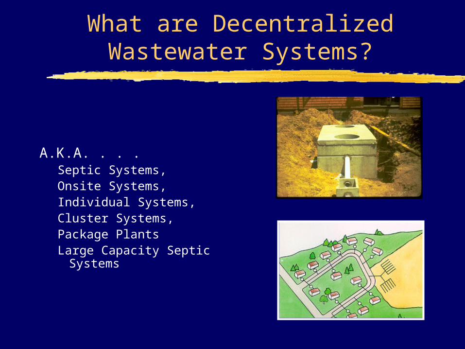
What are Decentralized Wastewater Systems?
A.K.A. . . . Septic Systems,Onsite Systems,Individual Systems,Cluster Systems,Package PlantsLarge Capacity Septic
Systems
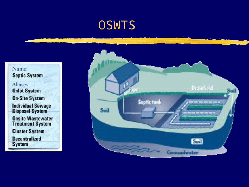
OSWTS
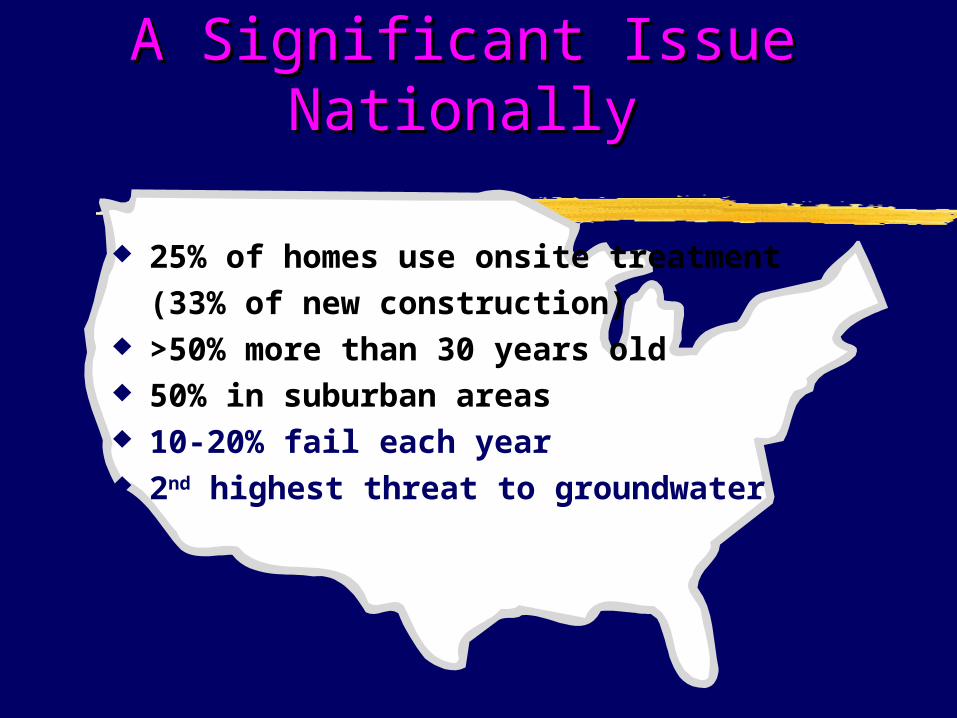
25% of homes use onsite treatment (33% of new construction)
>50% more than 30 years old 50% in suburban areas 10-20% fail each year 2nd highest threat to groundwater
A Significant Issue A Significant Issue NationallyNationally
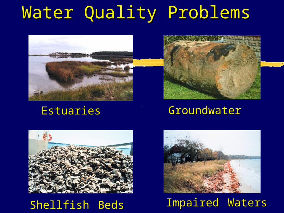
Water Quality ProblemsWater Quality Problems
EstuariesEstuaries GroundwaterGroundwater
ShellfishShellfish BedsBeds ImpairedImpaired WatersWaters
Who Regulates OSWTS?
State, Tribal, or Local Jusrisdiction In Washington: 246-272A small systems 246-272B LOSS 246-273 Additives
EPA provides information and guidance However some systems are regulated by
EPA Serve 20 or more people Receive industrial or commercial wastes
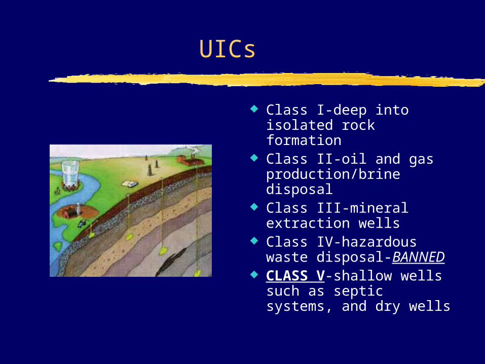
UICs
Class I-deep into isolated rock formation
Class II-oil and gas production/brine disposal
Class III-mineral extraction wells
Class IV-hazardous waste disposal-BANNED
CLASS V-shallow wells such as septic systems, and dry wells
Examples of Class V UIC
Gas Station Apartment Building Rest Stop with Cesspool Stripmall (e.g. w/ photoprocessor,
dry cleaner) Carwash
States Regulate Onsites . . . So Why is EPA Getting Involved??
Clean Water Act goals not being met
Major nonpoint source of pollution
Lack of funding: Need alternatives to costly centralized WWT
Regulatory Issues, e.g., UIC, stormwater phase II, NPDES
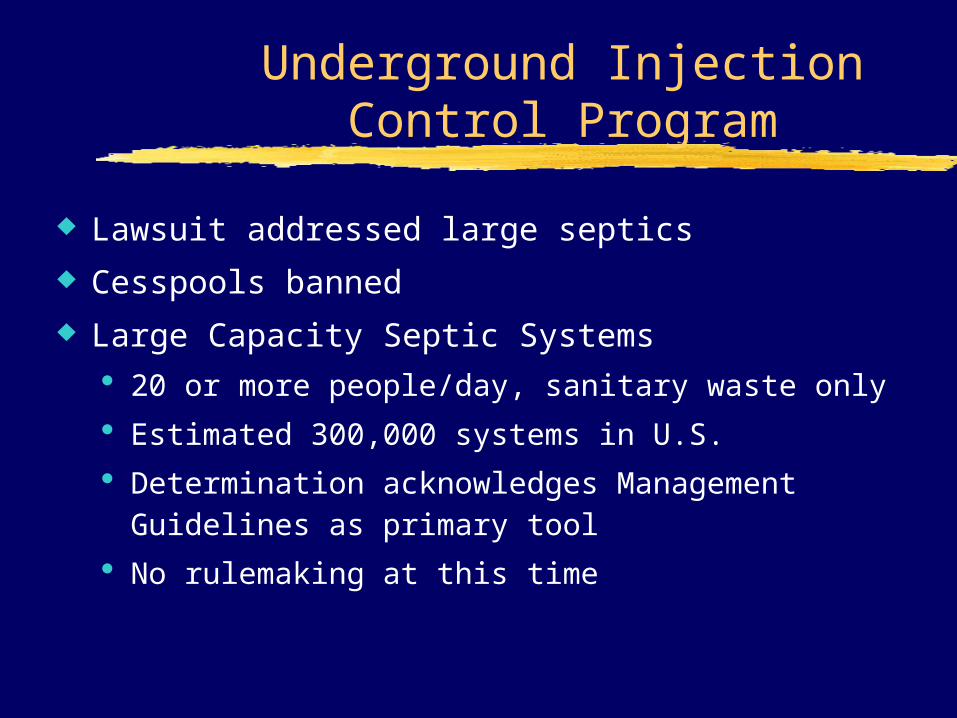
Underground Injection Control Program
Lawsuit addressed large septics
Cesspools banned
Large Capacity Septic Systems 20 or more people/day, sanitary waste only
Estimated 300,000 systems in U.S.
Determination acknowledges Management Guidelines as primary tool
No rulemaking at this time
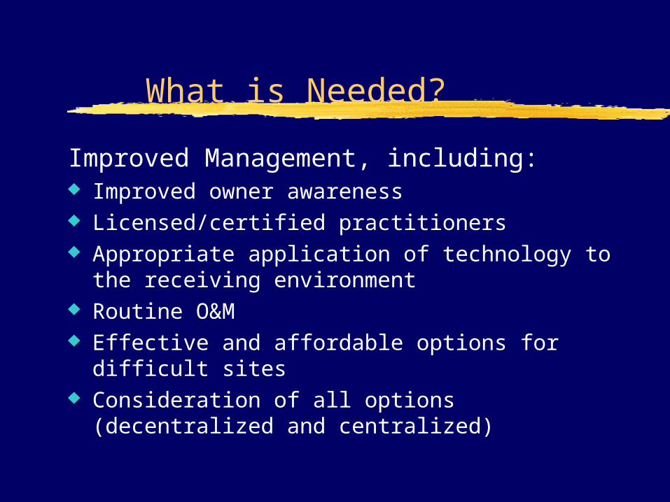
What is Needed?
Improved Management, including: Improved owner awareness Licensed/certified practitioners Appropriate application of technology to the
receiving environment Routine O&M Effective and affordable options for difficult
sites Consideration of all options (decentralized and
centralized)

In the beginning . . . .
And thou shalt have a paddle upon thy weapon, and it shall be:
when thou wilt ease thyself abroad, thou shalt dig therewith,
and shalt turn back and cover that which cometh from thee
Deuteronomy 23:13
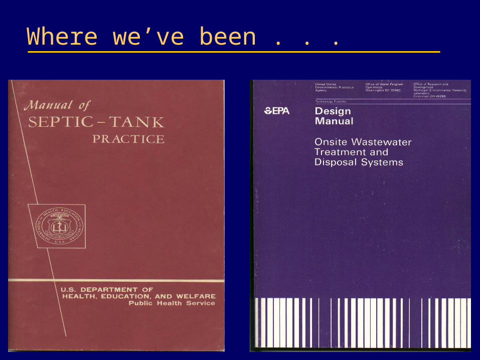
Where we’ve been . . .
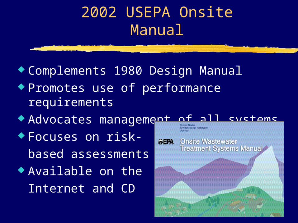
2002 USEPA Onsite Manual
Complements 1980 Design Manual Promotes use of performance
requirements Advocates management of all systems Focuses on risk-
based assessments Available on the
Internet and CD
How to access the OWTS Manual
CDs are available at the NEHA 2002 Conference.The online version is available at:
http://www.epa.gov/ORD/NRMRL/
To order a printed version, send a request to:
U.S. EPA/NSCEPP.O. Box 42419
Cincinnati, Ohio 45242-0419
Send an email to [email protected] call 1-800-490-9198 or (513) 489-8190
Summary of manual contents
Background and use of OWTSs Management of onsite systems System performance
requirements Treatment processes and
technologies Treatment system selection
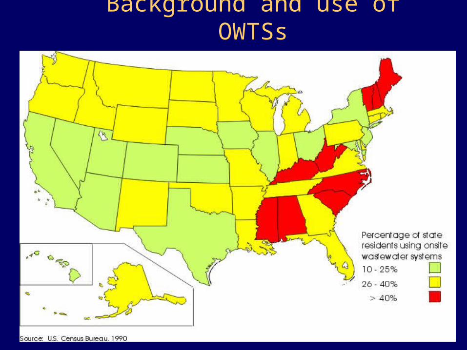
Background and use of OWTSs
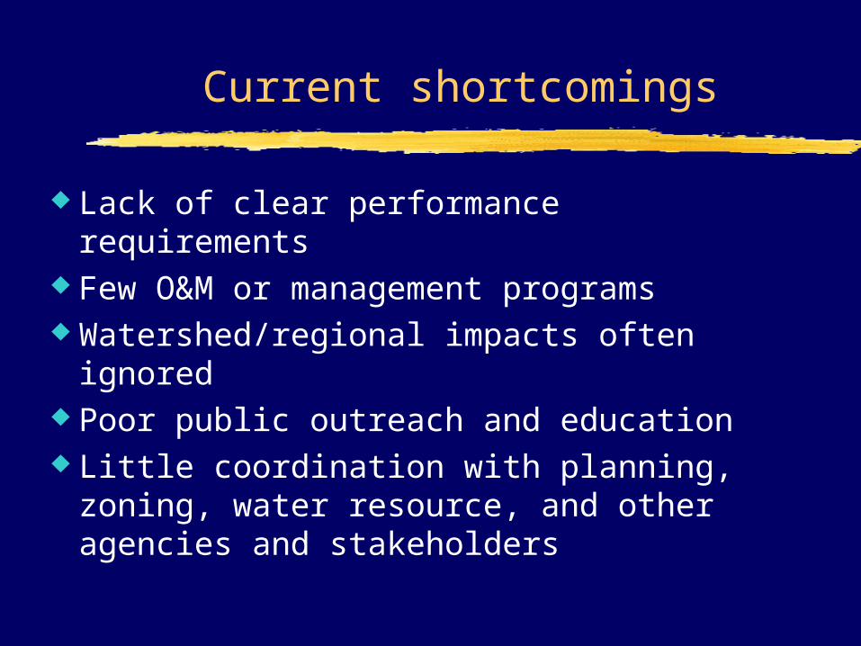
Current shortcomings
Lack of clear performance requirements Few O&M or management programs Watershed/regional impacts often
ignored Poor public outreach and education Little coordination with planning,
zoning, water resource, and other agencies and stakeholders
Reasons for concern
Public health Water quality Property
values Community
quality-of-life
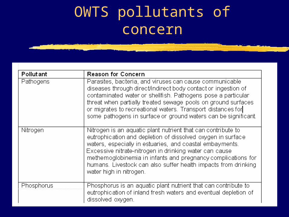
OWTS pollutants of concern
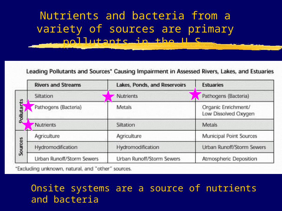
Nutrients and bacteria from a variety of sources are primary pollutants in
the U.S.
Onsite systems are a source of nutrients and bacteria
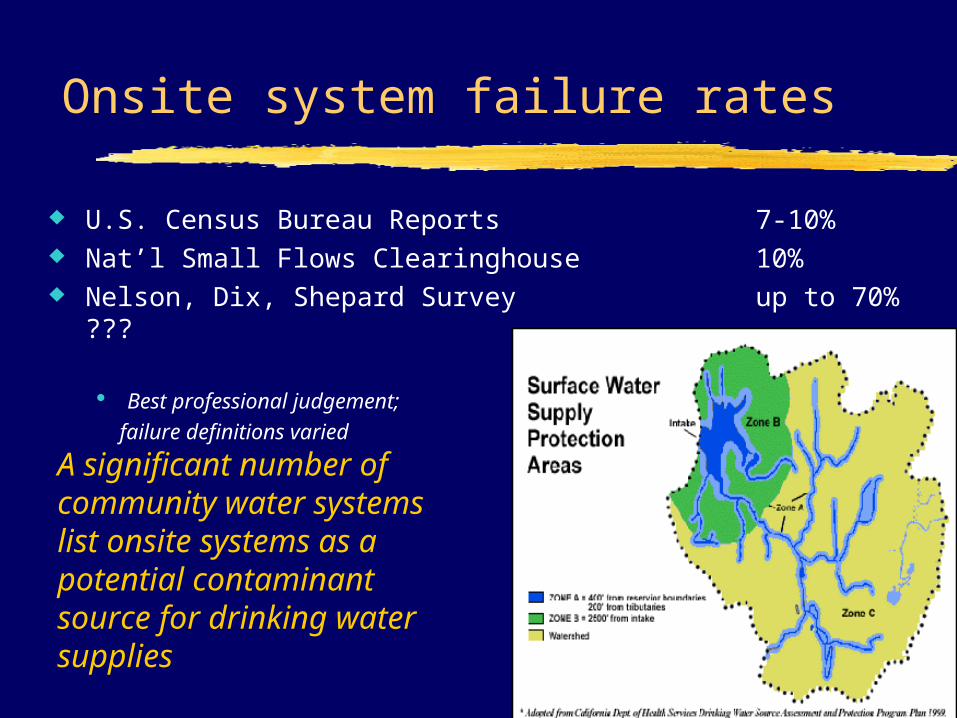
Onsite system failure rates
U.S. Census Bureau Reports 7-10% Nat’l Small Flows Clearinghouse 10% Nelson, Dix, Shepard Survey up to 70% ???
Best professional judgement; failure definitions varied
A significant number of community water systems list onsite systems as a potential contaminant source for drinking water supplies
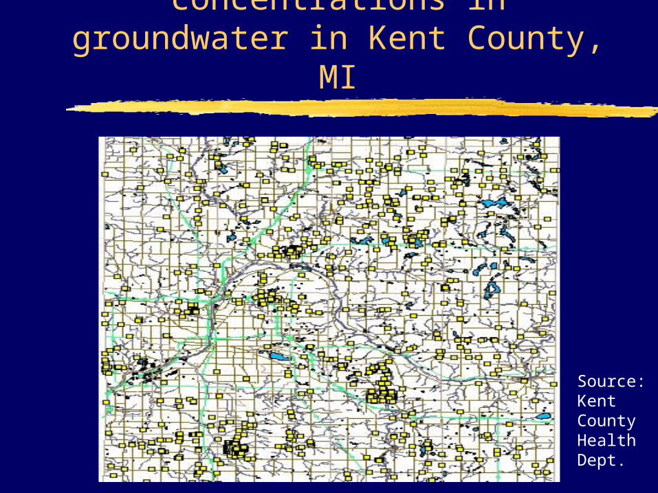
Elevated nitrate concentrations in groundwater in Kent County,
MI
Source: Kent County Health Dept.
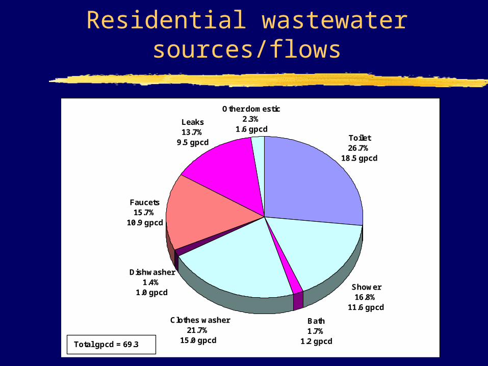
Residential wastewater sources/flows
Toilet 26.7%
18.5 gpcd
Shower 16.8%
11.6 gpcd
Bath 1.7%
1.2 gpcd
Clothes washer 21.7%
15.0 gpcd
Dishwasher 1.4%
1.0 gpcd
Faucets 15.7%
10.9 gpcd
Leaks 13.7%
9.5 gpcd
Other domestic 2.3%
1.6 gpcd
Total gpcd = 69.3
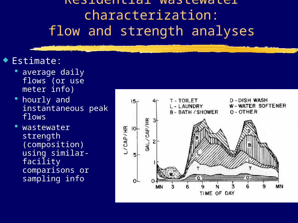
Residential wastewater characterization:
flow and strength analyses
Estimate: average daily flows
(or use meter info) hourly and
instantaneous peak flows
wastewater strength (composition) using similar-facility comparisons or sampling info
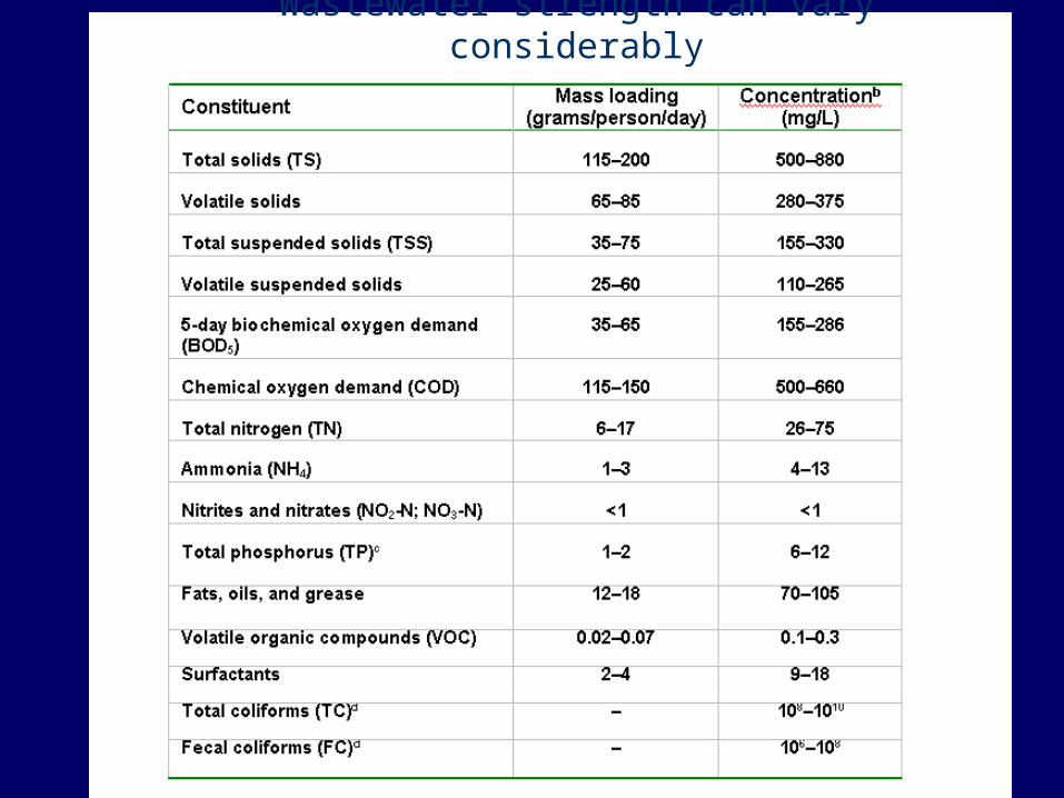
Wastewater strength can vary considerably
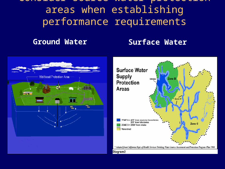
Consider source water protection areas when establishing performance
requirements
Surface Water
Ground Water
Onsite Regulation in Washington
http://www.doh.wa.gov/ehp/ts/waste.htm
http://www.doh.wa.gov/ehp/ts/ww/Prop-Treatment-Prod-RSG-1-10-2005.pdf
http://www.doh.wa.gov/ehp/ts/WW/246-272a-wac-final.pdf
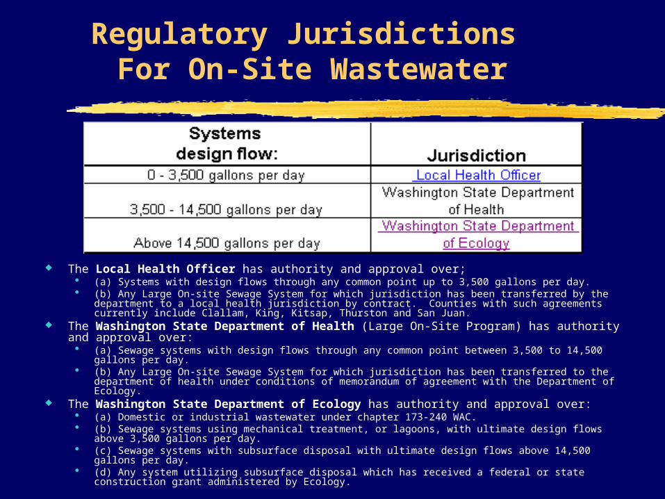
Regulatory Jurisdictions For On-Site Wastewater
The Local Health Officer has authority and approval over; (a) Systems with design flows through any common point up to 3,500 gallons per day. (b) Any Large On-site Sewage System for which jurisdiction has been transferred by the department
to a local health jurisdiction by contract. Counties with such agreements currently include Clallam, King, Kitsap, Thurston and San Juan.
The Washington State Department of Health (Large On-Site Program) has authority and approval over:
(a) Sewage systems with design flows through any common point between 3,500 to 14,500 gallons per day.
(b) Any Large On-site Sewage System for which jurisdiction has been transferred to the department of health under conditions of memorandum of agreement with the Department of Ecology.
The Washington State Department of Ecology has authority and approval over: (a) Domestic or industrial wastewater under chapter 173-240 WAC. (b) Sewage systems using mechanical treatment, or lagoons, with ultimate design flows above
3,500 gallons per day. (c) Sewage systems with subsurface disposal with ultimate design flows above 14,500 gallons per
day. (d) Any system utilizing subsurface disposal which has received a federal or state construction grant
administered by Ecology.
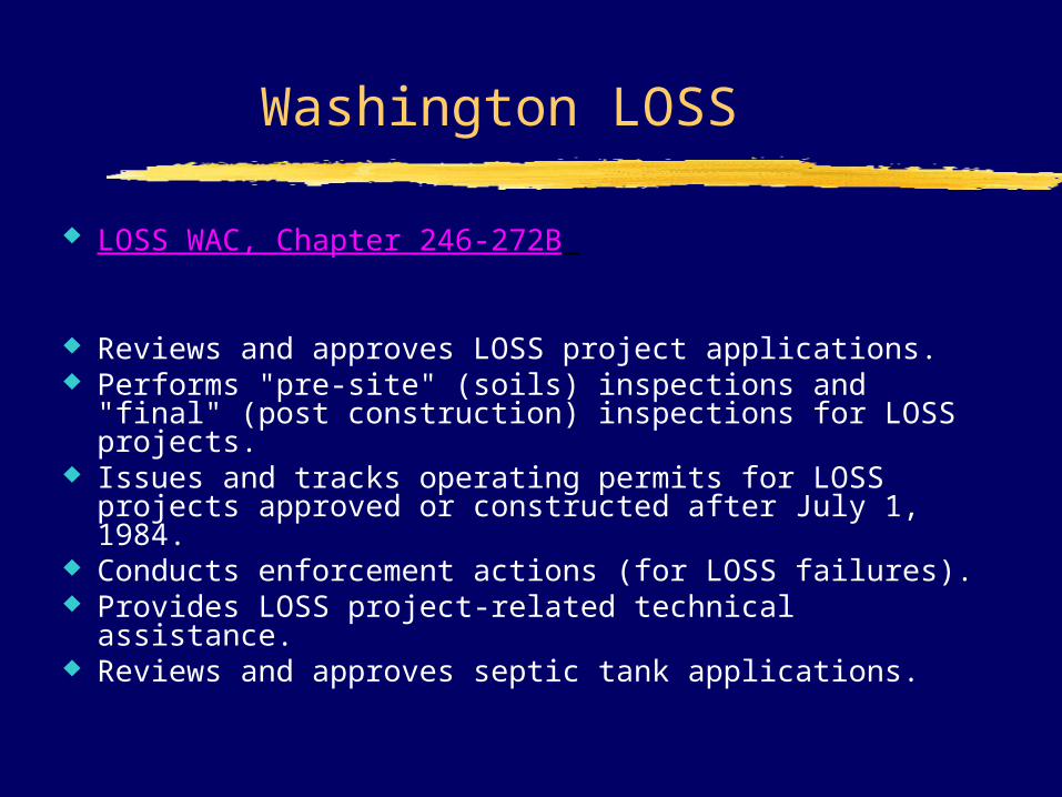
Washington LOSS
LOSS WAC, Chapter 246-272B
Reviews and approves LOSS project applications. Performs "pre-site" (soils) inspections and "final"
(post construction) inspections for LOSS projects. Issues and tracks operating permits for LOSS projects
approved or constructed after July 1, 1984. Conducts enforcement actions (for LOSS failures). Provides LOSS project-related technical assistance. Reviews and approves septic tank applications.
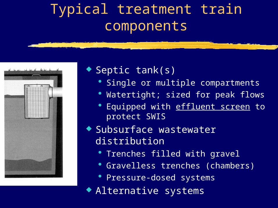
Typical treatment train components
Septic tank(s) Single or multiple compartments Watertight; sized for peak flows Equipped with effluent screen to
protect SWIS
Subsurface wastewater distribution Trenches filled with gravel Gravelless trenches (chambers) Pressure-dosed systems
Alternative systems
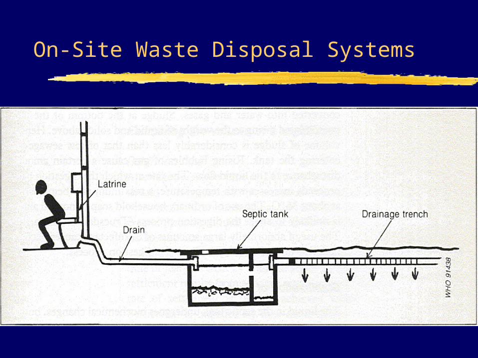
On-Site Waste Disposal Systems
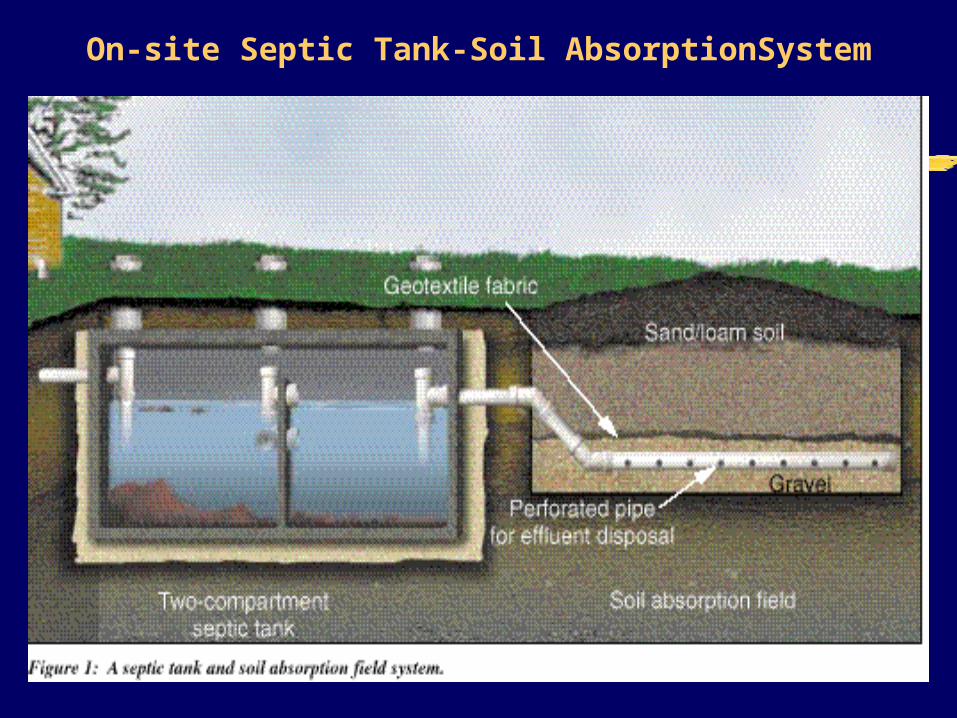
On-site Septic Tank-Soil AbsorptionSystem

Septic Tank-Soil Absorption System for On-Site Sewage Treatment
Used where there are no sewers and community treatment facilities: ex.: rural homes
Septic tank: solids settle and are digested
Septic tank effluent (STE) is similar to primary sewage effluent
Distribute STE to soil via a sub-surface, porous pipe in a trench
Enteric microbes are removed and retained by the soil and biodegraded along with STE organic matter; extensive enteric microbe reductions are possible
Viruses and other smaller pathogens can migrate through soil and reach ground water if the soil is too porous (sand) and the water table is high
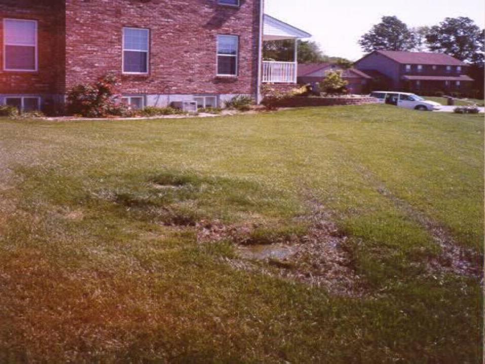
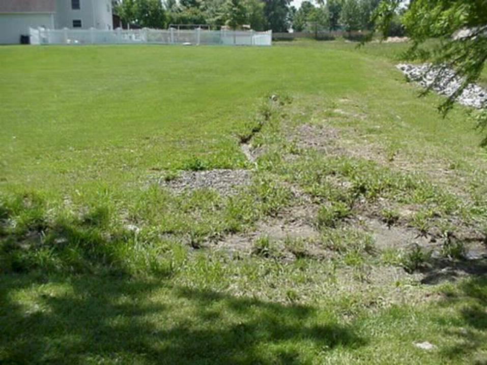
STE and pathogens can migrate to surface if soil is too impervious (clay soils)
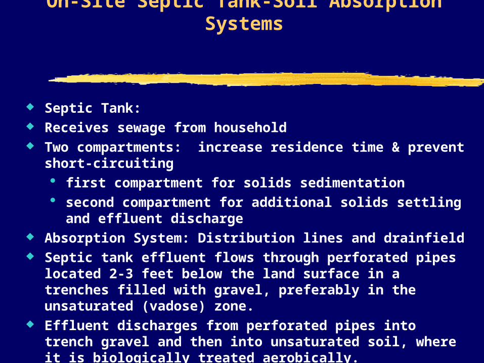
On-Site Septic Tank-Soil Absorption Systems
Septic Tank: Receives sewage from household Two compartments: increase residence time & prevent short-circuiting
first compartment for solids sedimentation second compartment for additional solids settling and effluent discharge
Absorption System: Distribution lines and drainfield Septic tank effluent flows through perforated pipes located 2-3 feet below the
land surface in a trenches filled with gravel, preferably in the unsaturated (vadose) zone.
Effluent discharges from perforated pipes into trench gravel and then into unsaturated soil, where it is biologically treated aerobically.
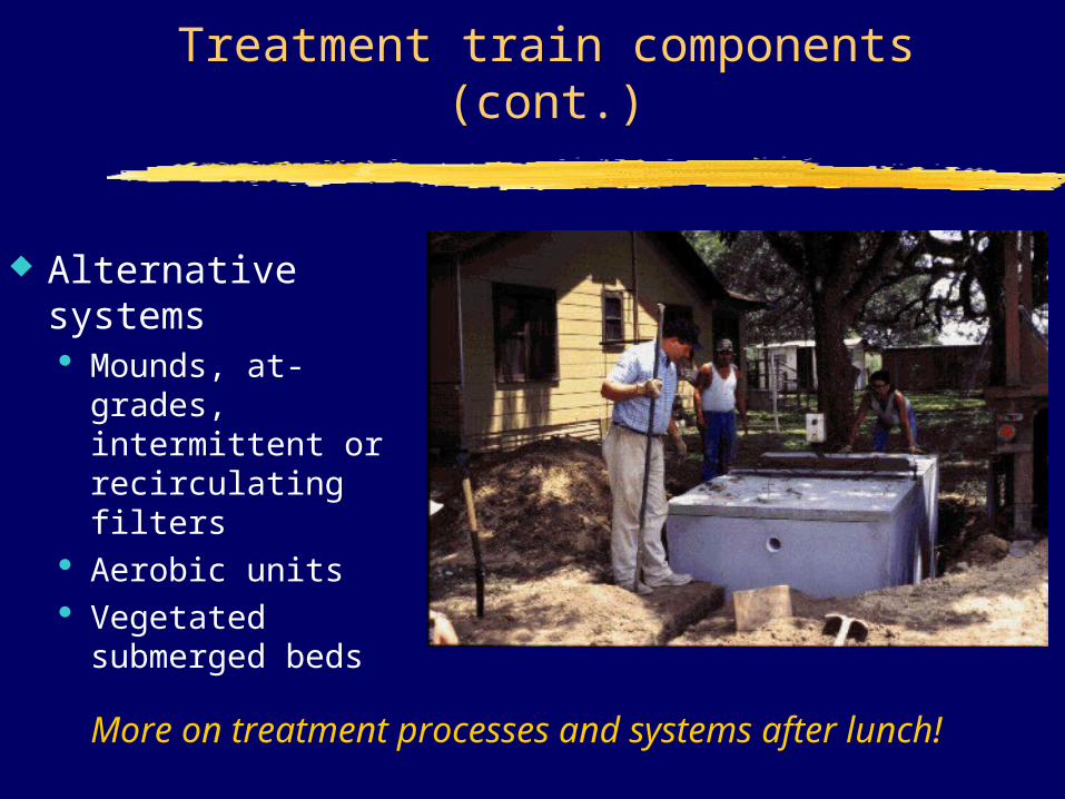
Treatment train components (cont.)
Alternative systems Mounds, at-
grades, intermittent or recirculating filters
Aerobic units Vegetated
submerged beds
More on treatment processes and systems after lunch!
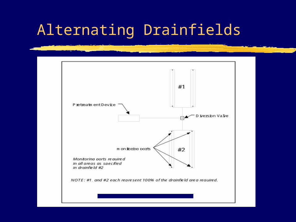
Alternating Drainfields
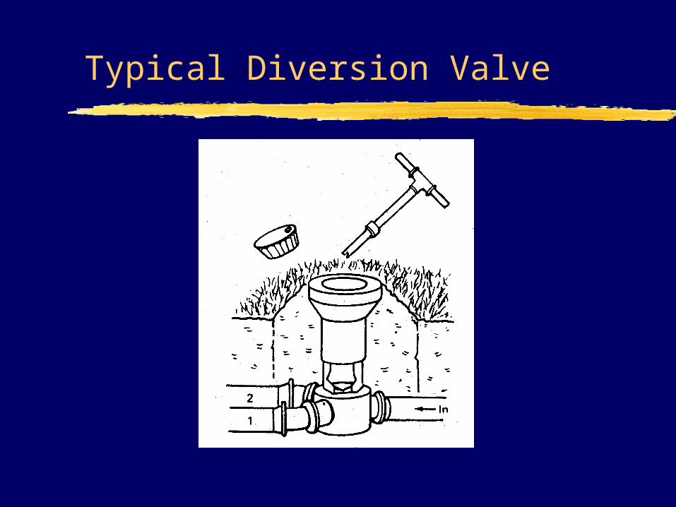
Typical Diversion Valve
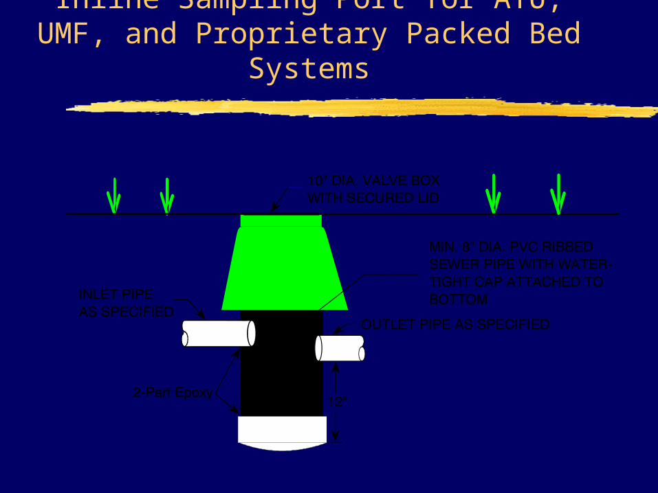
Inline Sampling Port for ATU, UMF, and Proprietary Packed Bed Systems
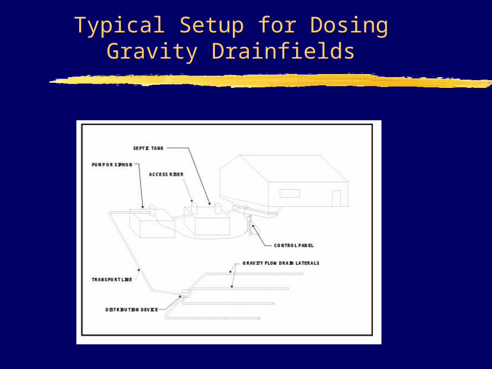
Typical Setup for Dosing Gravity Drainfields
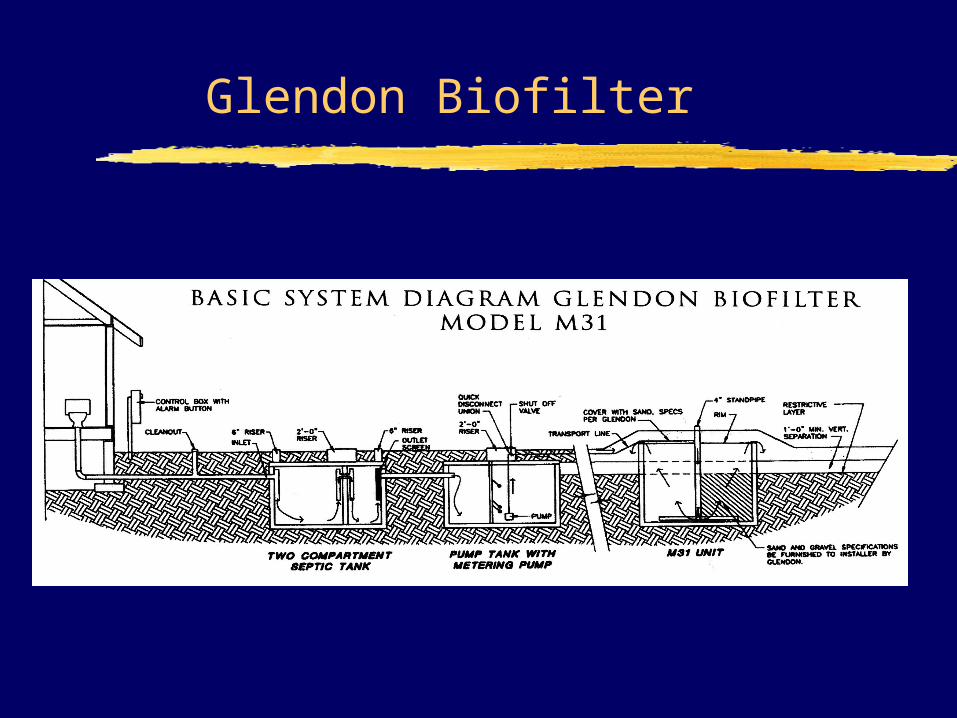
Glendon Biofilter
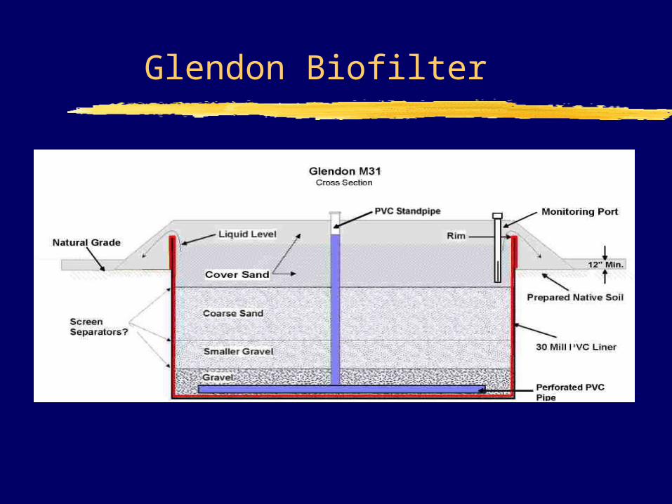
Glendon Biofilter
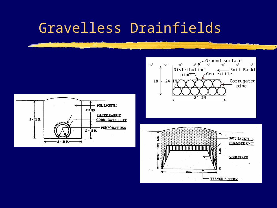
Gravelless Drainfields
Ground surface
Corrugatedpipe
Soil Backfill
18 - 24 IN.
24 IN.
Distributionpipe Geotextile
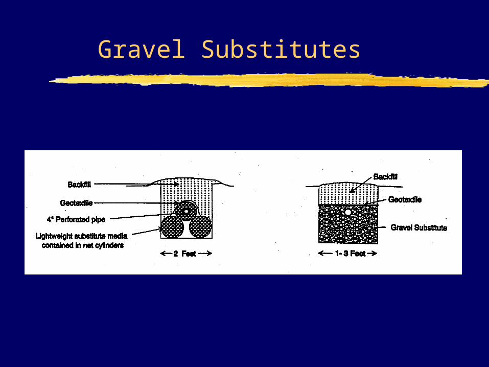
Gravel Substitutes
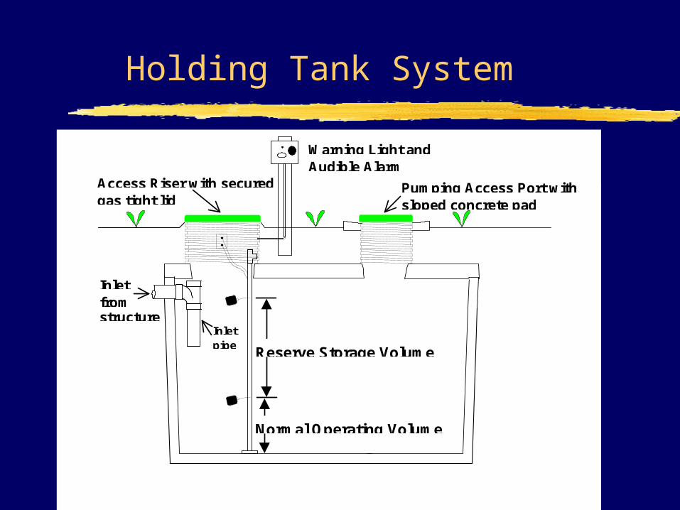
Holding Tank System
Inletfromstructure
Inletpipe Reserve Storage Volume
Normal Operating Volume
Access Riser with securedgas tight lid
Pumping Access Port withsloped concrete pad
Warning Light andAudible Alarm
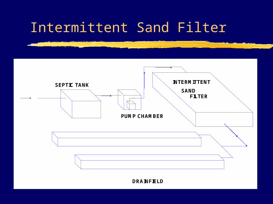
Intermittent Sand Filter
SEPTIC TANK
PUMP CHAMBER
SANDFILTER
DRAINFIELD
INTERMITTENT
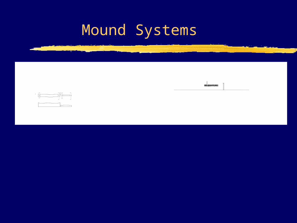
Mound Systems
Septic Tank Pump Chamber Mound
TopsoilCap Fill Material
Plowed Area
Water Table or Creviced Bedrock
Topsoil
Cap Approved SyntheticFilterFabric or Geotextile
Fill Material
Plowed Area
Highly or Excessively Permeable Soil
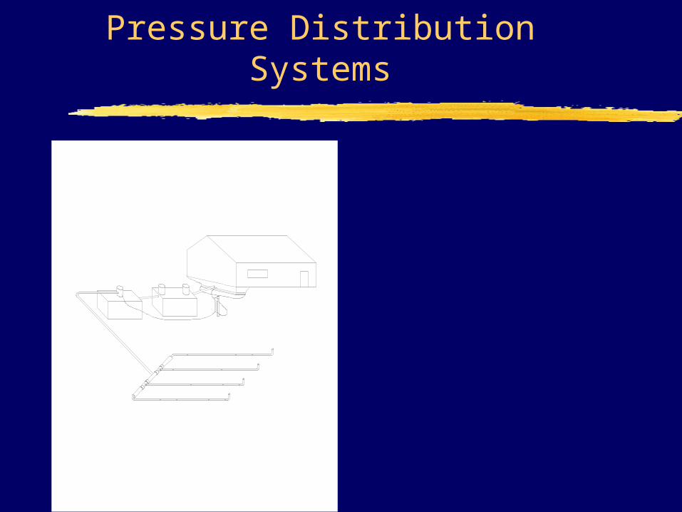
Pressure Distribution Systems
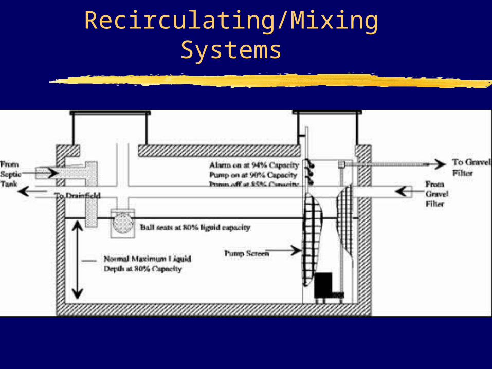
Recirculating/Mixing Systems
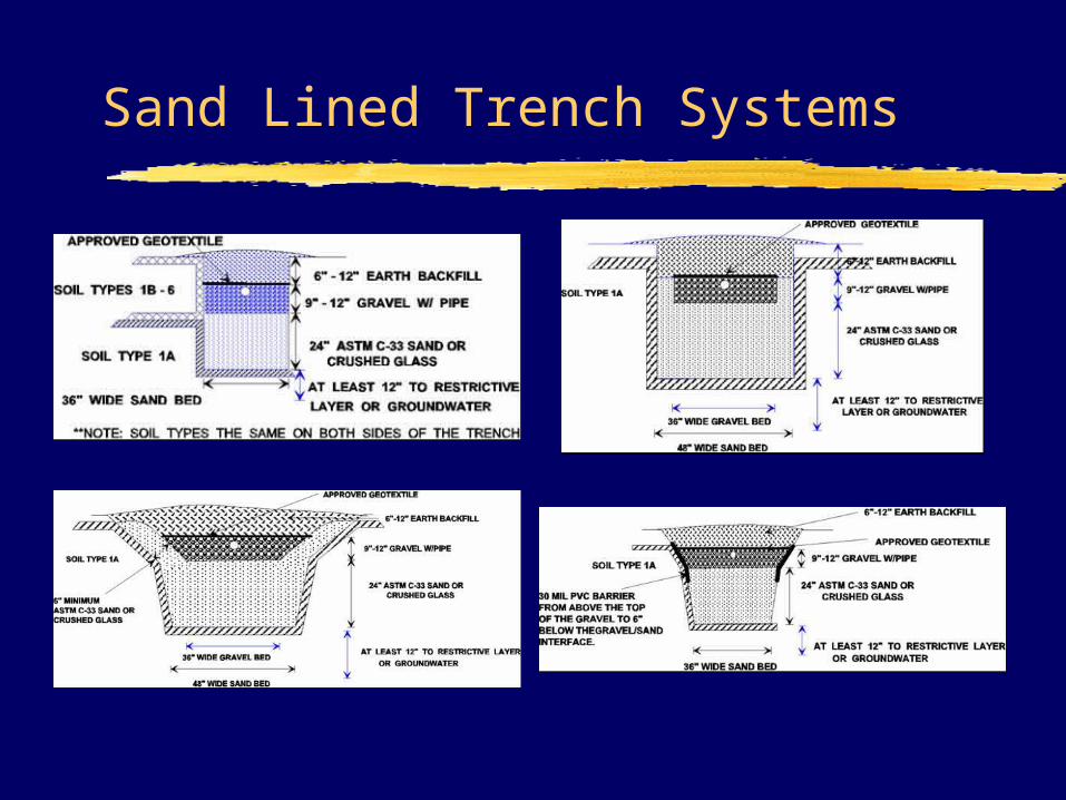
Sand Lined Trench Systems
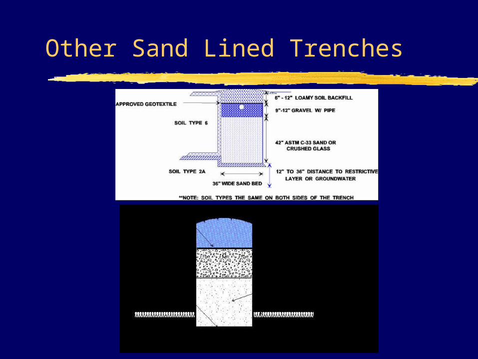
Other Sand Lined Trenches
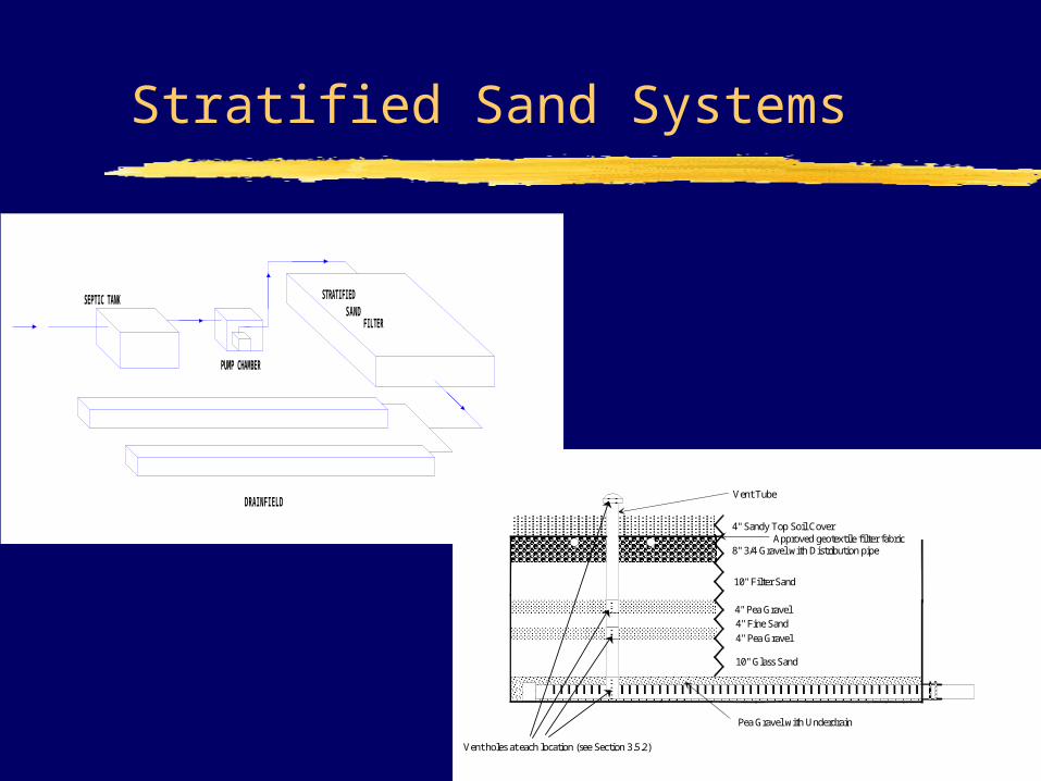
Stratified Sand Systems
SEPTIC TANK
PUMP CHAMBER
SANDFILTER
DRAINFIELD
STRATIFIED
4" Sandy Top Soil Cover
8" 3/4 Gravel with Distribution pipe
10" Filter Sand
4" Pea Gravel
4" Fine Sand
4" Pea Gravel
10" Glass Sand
Pea Gravel with Underdrain
Vent Tube
Approved geotextile filter fabric
Vent holes at each location (see Section 3.5.2)
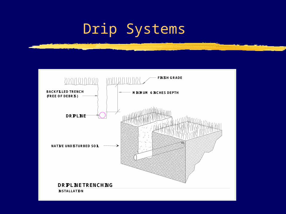
Drip Systems
FINISH GRADE
DRIPLINE
BACKFILLED TRENCH
INSTALLATION
(FREE OF DEBRIS)
DRIPLINE
NATIVE UNDISTURBED SOIL
MINIMUM 6 INCHES DEPTH
TRENCHING
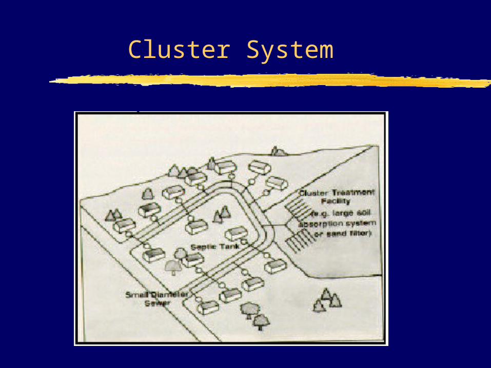
Cluster System