ON-SITE WASTEWATER DISPOSAL SYSTEM ... WASTEWATER DISPOSAL SYSTEM INSTALLATION MANUAL A helpful,...
50
ON-SITE WASTEWATER DISPOSAL SYSTEM INSTALLATION MANUAL A helpful, concise manual and guidebook for new and experienced septic system installers State of New Hampshire DEPARTMENT OF ENVIRONMENTAL SERVICES Subsurface Systems Bureau 29 Hazen Drive, PO Box 95, Concord, NH 03302-0095 603-271-3501 Produced by Granite State Designers and Installers Association as part of a grant it received from the N. H. Department of Environmental Services, using funds from the U. S. Environmental Protection Agency
-
Upload
phungtuong -
Category
Documents
-
view
215 -
download
0
Transcript of ON-SITE WASTEWATER DISPOSAL SYSTEM ... WASTEWATER DISPOSAL SYSTEM INSTALLATION MANUAL A helpful,...

ON-SITE WASTEWATER
DISPOSAL SYSTEM
INSTALLATION MANUAL
A helpful, concise manual and guidebook for new and experienced septic system installers
State of New Hampshire DEPARTMENT OF ENVIRONMENTAL SERVICES
Subsurface Systems Bureau 29 Hazen Drive, PO Box 95, Concord, NH 03302-0095
603-271-3501
Produced by Granite State Designers and Installers Association as part of a grant it received from the N. H. Department of Environmental Services, using funds from the U. S. Environmental Protection Agency

3

Introduction/Forward
The creation of this manual is the result of a collaborated effort between the N. H. Department of Environmental Services Subsurface Systems Bureau, and Granite State Designers and Installers Association, the state’s trade association for septic system designers, installers, pumpers, and allied professionals and regulatory agencies.
It’s purpose is to help both new and experienced septic system installers and excavators by providing needed and helpful information and tips to properly site and install a state approved septic system design.
Also contained within this manual are helpful tips on how to prepare for the septic installer’s permitting exam. Commonly used forms, and a glossary of commonly used terms are also enclosed.
Granite State Designers and Installers Association is grateful to these individuals who assisted with development of this manual. Without their help, this manual would not have been produced:
--Gerald H. Miller, LLS, Hampton --Carl Hagstrom, Monadnock Septic Design, Fitzwilliam --Thomas Canfield, Canfield Earth Construction, Rochester --Kenneth Bradley, Jr., Waste, Inc., Concord --Alan Moody, A. M. Designs, Concord --Joe Foley, Foley’s Septic Design, Epping --Jay Baas, Subsurface Systems Bureau, N. H. Dept. of Environmental Services
Funding for this project was provided, in part, by a Local Water Protection Grant, awarded to Granite State Designers and Installers Association by the N. H. Department of Environmental Services, using funds of the U. S. Environmental Protection Agency (Account number: 025-044-2025-090-0515).
--Richard H. Clough, CAE, Executive Director, Granite State Designers and Installers Association
1

2

TABLE OF CONTENTS
Acknowledgments............................................................................................................................1
Table of Contents.............................................................................................................................3
Current Rules and Regulations for Installation of a Septic System.................................................5
System Operation and Function.......................................................................................................6
The Very Basics...............................................................................................................................9
Reading Septic Plans and Understanding Designer s Intent.........................................................10
Working with Amended vs. Revised Plans....................................................................................11
Creating Cost Estimates, Using Specified Materials .....................................................................12
Assuring Proper Site Layout..........................................................................................................18
Using Appropriate Fill Sands and Materials..................................................................................21
Choosing Appropriate Septic Stone...............................................................................................22
Site Work and Construction Techniques .......................................................................................23
Safety on the Job Site.....................................................................................................................35
Some Key Definitions (glossary)...................................................................................................40
State Laws Relative to Septic Design and Installation ..................................................................42
-3-

4
Current Rules And Regulations To Become A Licensed Septic Installer
New Hampshire state law (RSA 485-A:36) mandates anyone engaging in the installation of sub-surface sewage or waste disposal systems to first obtain an installer’s permit from the N. H. Department of Environmental Services Subsurface Systems Bureau. (Only exception: “Any person who desires to install or repair a waste disposal system for his own domicile shall not be required to obtain an installer’s permit as provided in paragraph I, provided he complies with rules adopted by the division relative to such systems.”)
To secure an installer’s permit applicants are required to pay a $40 application fee and must demonstrate, via an exam, a sound working knowledge of state laws and rules pertaining to septic systems (RSA 485-A:29-36, and state Env-Ws 1000 series rules). Applicants should also have the ability to read and understand approved waste disposal system plans.
Applications can be requested via mail by writing to the Bureau at NHDES Subsurface Systems Bureau, P.O. Box 95, Concord, NH 03302, Tel. 271-3501, or via download from the Bureau’s web site at: www.des.state.nh.us/ssb. Completed applications, along with the $40 fee must be postmarked by the Bureau by the first day of the month of the scheduled exam.
State exams to determine knowledge are given two times a year by the Subsurface Systems Bureau in April and September. One week prior to the exam, a free three-hour review and discussion session is offered to installer candidates at the NHDES’ Concord offices. The passing grade for certification is 80 percent. The exam is an open-book exam consisting of two sections to be completed within two hours. A candidate may retake the installer exam by making an appointment to do so, and by paying another $40 application fee.
Studying of applicable state laws, and the Sub-division and Individual Sewage Disposal System Design Rules (see specific references above), should be the basis for preparing for the permit exam. Copies of the sewage disposal rules can be secured from the Subsurface Systems Bureau at a cost of $10, or can be accessed on-line at the Bureau’s web site (see address above). RSA-A:29-36 appears as an appendix to this manual.
Installer’s permits are issued on a calendar year basis, and expire at December 31 each year, unless renewed upon proper application and payment of the $40 annual fee.
Installer’s permits can be suspended, revoked, or not renewed for just cause, including, but not limited to, the installation of a waste disposal system in violation of state law and regulations, or the refusal by a permit holder to correct defective work. NHDES may not suspend, revoke, or refuse to renew a permit, except for just cause, until a permit holder has had opportunity to be heard by the NHDES Water Division.
CONTACT INFORMATION: Subsurface Systems Bureau, N. H. Department of Environmental Services, Hazen Drive,
P.O. Box 95, Concord, NH 03302, Tel. (603) 271-3501 or on line at www.des.state.nh.us/ssb.
5

Septic System Operation and Function
Normal household wastewater consists of all the liquid household waste generated from the toilet, bath and laundry. This material is composed of about 99 percent liquids and about one percent solids. The small percentage of solids and microorganisms in wastewater are the cause of health hazards and nuisances.
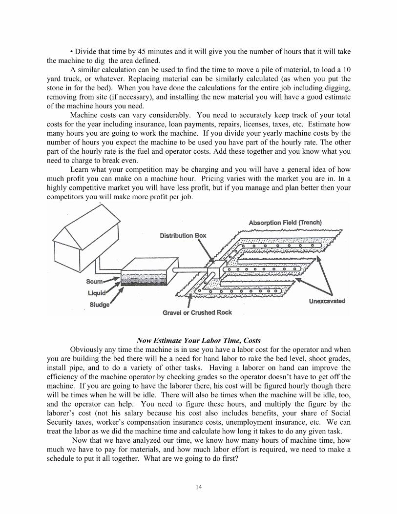
A properly functioning septic/wastewater system is one which will not allow harmful pollutants to accumulate to dangerous levels in the environment. The essential features of a typical system are the sewer drain line leading from the building, treatment/septic tank, an effluent line leading from the septic tank to a distribution box, the distribution box itself, the disposal field, and surrounding soil that will accept treated effluent.
The Treatment/Septic Tank The treatment/septic tank functions as a conditioning device to provide for primary
treatment of the wastewater. Raw wastewater is detained in the treatment tank long enough for it to be rendered more suitable for discharge to the disposal area. If raw wastewater were to be discharged directly to the disposal area, the pore spaces between the soil particles would quickly become clogged by the solid materials contained in the wastewater and would cause back-ups in the plumbing system into the house, or come to the surface of the ground near the disposal area.
To minimize likelihood of such an occurrence, raw wastewater is held for a period of one to three days in the septic/treatment tank and subjected to a combination of physical, chemical and biological actions, which result in the conversion of most of the solid materials to liquids or gases. Gases either escape through the house plumbing vent or mix with the effluent, and the clarified liquid is channeled to the disposal field. Some of the solids remain in the tank as sludge or scum and must be removed periodically before they accumulate to the point where they will be carried over into the disposal field.
6

The Effluent Line The effluent line is a water tight pipeline which conveys the treatment tank effluent to the
disposal area. Flow is usually by gravity but may be pumped in certain instances. There should be a drop in elevation between the treatment tank and disposal field of 1/8 inch per foot or more with a gravity effluent line. This drop is to prevent a sluggish disposal area. The drop also prevents occasional large peak flows from backing up during periods of stress and causing the liquid level in the septic tank from rising above the baffles.
The Distribution Box When more than one disposal line is required through the disposal area, or multiple
disposal areas are used, a means of distribution is needed to assure use of the entire area. This can be accomplished by using a distribution box. A distribution box is a small tank with a single inlet, and several outlets below the inlet. Distribution boxes should be insulated, include adequate flow baffles, be carefully installed level, and installed to minimize shifting or settling.
The Disposal Area The disposal area which disperses wastewater to the ground once it passes through the
distribution box may vary from five to 20 or more feet wide. In trench type systems, water flows through perforated parallel piping where effluent seeps into the receiving soil. Size of this leaching area will vary dependent upon expected loading. Care should be given during installation to assure piping is level to accept wastewater in equal amounts throughout the entire leaching area.
Proprietary Disposal Devices: As an alternative to trenching leaching systems, some designers are using a variety of proprietary devices to provide open areas, or void space, in the soils into which effluent from septic tanks can be introduced, and then absorbed by the soil. Septic system rules allow for a reduction in the size of the disposal area when these proprietary products are used because they create an unmasked interface between the effluent and the soil. The various proprietary products have advantages due to smaller required footprints, and ease of installation.
Bed Disposal Area A disposal area acts as an underground retention area. Stone (1 1/2" nominal in
diameter) is typically used in the construction of a bed to provide void space for the storage of effluent and to allow it to drain slowly through the soil. Bed size is calculated by multiplying the expected volume of wastewater expressed in gallons per day by the size rating parameter determined by the soil evaluation.
7

The conditioned wastewater effluent from the treatment tank is discharged into the soil at a shallow depth by means of the bed disposal area. The disposal area serves the function of absorbing the effluent load from the treatment tank, serving as a temporary storage area during periods of large water use, and providing additional treatment of the effluent.
The Soil The soil into which the effluent is discharged, serves three additional purposes. One is to
distribute and absorb the effluent. The second is to provide microorganisms and oxygen for the treatment of the unstable compounds, bacteria and solids. The third is to provide chemical and cation exchange reactions to remove nutrients from the wastewater.
Disposal of liquids into the soil from a disposal area is through soil pores, between soil aggregates and through root channels. The soil pores vary in size with soil texture. Soil texture, soil structure, moisture content, and root penetration also effect the liquid movement through the soil.
Size of the soil pores influences the permeability rate, which in turn determines the amount of wastewater the soil can absorb. Soils with very fine textures (silts and silty clay) can absorb effluent only at a very slow rate, while sandy soils with coarse textures can absorb larger quantities of effluent. The texture of the soil is an important factor in determining the suitability of a particular soil for wastewater disposal.
The liquid movement from a disposal area into the surrounding soil is by gravitational and hydrostatic pressure, as well as capillary or matrix tension. Coarse textured soils (sands, or loamy sands) rely on the large pores for water movement and are primarily influenced by gravitational pressure. Finer textured soils (silt loams, silts, silty clay loams) mostly depend upon the smaller capillary pores for water movement. In small pores, capillary attraction tends to retard the pull of gravity and slow the percolation rate. Only in the larger soil pores does the water move with any degree of speed.
by Richard H. Clough, CAE, Executive Director, Granite State Designers and Installers Association, Concord
8
What Septic System Installers Need To Be Aware Of: The Very Basics
Here are some basics septic system installers need to be aware of: • Septic systems should be installed using only approved septic plans and a copy of the
N. H. Department of Environmental Services Approval for Construction form. Look for the formal approval stamp from NHDES, the designer’s stamp, and the NHDES Sub Surface Bureau Construction Approval form.
• Read, study and understand the approved plans, and various conditions included thereon. Install and build in conformity with these plans.
• Read and understand the NHDES Subsurface System Bureau Sub-Division and Individual Sewage Disposal System Rules (Env-Ws 1000 Series Rules) applicable to system installations...before installing any system. As a state permitted installer, you are expected to know, and abide, by these rules.
• Before installing the system, look for conditions that might be included on the NHDES construction approval form. Abide by the conditions when installing. This is very important.
• In accordance with RSA 485-A:29, there shall be an inspection by the NHDES Subsurface Systems Bureau before the system is covered and placed in operation.
• When system is installed and prior to the NHDES inspection, all changes/amendments from approved plans must be documented on the amended plans.
• Any changes to the location or elevation of the leaching field will require revised, and approved plans. Such changes will require re-submission of the plans to the NHDES Subsurface Systems Bureau for re-approval. (Contact your designer prior to making any changes.)
by Carl Hagstrom, Monadnock Septic Design, Fitzwilliam
9

Installing Systems Consistent with Designer’s Plans, and Understanding Designer’s Intent
As you are probably aware, only approved septic plans are permitted to be installed. Be sure you have a copy of the construction approval form completed by the N. H. Department of Environmental Services before you begin installation.
To construct a system not consistent with state approved plans can put a septic installer’s permit in jeopardy, and can result in significant future liability on your part. Therefore, be sure you understand the plans you have been asked to construct.
Be sure: --you are working from state approved septic plans, and build your system consistent
with that plan. --to read and understand the descriptive information on the plan, and double-check
distances, elevations, etc. --what is placed on the plans is reasonable and buildable. If plans do not make sense, or
you find inaccuracies, go back to the designer before you start construction. Understanding “designer’s intent” is the one of the most important components in
reading plans, and constructing thereto. Design intent is meant to be used to establish the elevation of the bottom of the effluent disposal system (EDS).
Somewhere on the septic design plan there should be an area where, in accordance with New Hampshire Code of Administrative Rules Env-Ws 1003.06 (af), the design intent shall be stated clearly on the plan as follows:
(1) “The bottom of the effluent disposal system (EDS) shall be constructed at_________ elevation”; and
(2) “There is/are approximately ________ foot/feet above, at, or below original ground on the high contour of the designed effluent disposal system (EDS)”.
Item 1 is the contour elevation that is tied to the benchmark references shown on the plan, and is the design intent for the relationship to the rest of the system components and construction. It is used as an elevation reference for site preparation.
Item 2 is the spot elevation separation between the original surface elevation of the ground at the point underneath the system located at the highest contour elevation on the slope.
This high point contour elevation plus or minus the number of feet indicated should equal the elevation value as shown in Item (1), and is to be used as a check in the field to make sure that no anomalies in the design exist. If it is off by more than half a contour, the designer should be contacted before work proceeds.
by Gerald Miller, Licensed Land Surveyor, Certified Wetland Scientist and Permitted Septic Designer, Hampton, NH
10

Working with Amended vs. Revised Plans
The NHDES Subsurface Systems Bureau Rule Env-Ws 1003.12 requires the effluent disposal system to be installed according to the approved plans. If any changes become necessary, STOP installing. Always call the designer before changing anything and to discuss any changes the owner may ask you to make on site.
Revised plans are required if the leaching portion of the effluent disposal system moves up, down, sideways, turns, gets larger or smaller, or a pump must be added. In these cases, a new application, fee, and plans are required by the Sub Surface Systems Bureau, and must be approved by them before installation. Revised plans always require re-submission.
Amended plans are required if any components of the effluent disposal system such as house, tank, or well move, but the location, size and elevation of the effluent disposal area stays the same. Amended plans are also required by the Subsurface Systems Bureau prior to inspection if a pump is to be eliminated. No application, fees or re-approval by NHDES’ Sub Surface Systems Bureau are necessary in these instances.
Always have changed plans ready for the state inspector before he/she arrives on site for the inspection.
Installers who make unauthorized changes in the effluent disposal system installation could be required to remove the changed components and rebuild the system to designer/inspector specifications. Avoid potential liability by installing from an approved plan and make no unauthorized changes on site.
by Jay Baas, Subsurface Systems Bureau, NH Department of Environmental Services
11
Estimating Construction Costs
Estimating costs for a septic system can be a simple technique that becomes easier the more it is done. In this section we will explain the basis for estimating material, labor and machine costs at a very basic level. After you understand the approach it will be easy for you to develop your own guidelines and procedures for quick assessment and estimating.
If you were building a work bench chances are you would make a list of the materials needed, and go to your local home supply store to buy everything needed. Installing a septic system should be no different.
The first step is to review the state approved and stamped plans supplied by the designer. Make sure you read, study, and understand the plan and the designer’s intent. Do a site visit. Make sure you know where the bench marks and tie marks are, and verify that contours on the plans match the lay of the land.
Estimating Material Costs Then its time to make a complete list of the materials you will need, and get prices on
each. Take time to carefully think through the entire installation process. Be sure to review the plans carefully so you’ll purchase all items specified...and even things not specified. As an example: You may need to make baffles if the tank doesn’t come with them and you may need to install a filter.
Here’s an example of what you might need for one type of system: Quantity Description Your Cost
2 10 ft S&D 4” pipe $ 15 10 ft perforated 4” pipe $ 6 elbows 4” $ 1 1500 gallon septic tank $ 1 5 outlet d-box $
...and so on, until you have a complete list of all the manufactured components that you have to buy.
Next, you need to estimate how much septic stone, septic sand and fill material you will need to meet state requirements. Are you going to buy it delivered, or are you going to haul it yourself? There is a cost either way. Which is best for you?
If you have a 40’ by 30’ stone and pipe bed going in that has 18 inches of stone, then you need 1800 cubic feet of septic stone (30 x 40 x 1.5). To convert this to cubic yards you need to divide by 27 as there are 27 cubic feet in one cubic yard. This would mean you need to get 66.7 cubic yards of stone. But wait.
Your hole will be a little bigger than necessary, a little will get wasted in handling, so order 5 to 10 percent more than you need.
Calculate the septic sand the same way. Maybe in this example we need 6 inches of septic sand just below the stone. Again we multiply the length 40’ times the width of 30’ times
12
the thickness of .5’. (40' x 30' x .5'=600 c/f) We, therefore, need 600 cubic feet of septic sand, or 22.2 cubic yards (again 600 c/f divided by 27=22.2 cubic yards).
We could calculate the fill material the same way. If the fill is on a slope, then average the thickness required on the high side and the low side. This will generally be pretty close, but remember if it is a raised system the fill must extend 5’ all around it, so the area is going to be larger, but it can be calculated in a similar way.
Did you save the topsoil that was there? Will there be enough to finish the job with? 4” of top soil is generally the minimum you need in New England to grow good grass that will survive from season to season. Estimate it the same way: square footage area multiplied times thickness (all dimensions in feet). Then, divide by 27 and you have the cubic yards of topsoil that you need.
At this point we have one third of the cost done. We now have a list of all the purchased materials that we need and we know what they are going to cost.
Estimating Machine Time, Costs and Labor Estimating machine time involves breaking down the individual tasks and analyzing them
separately. How much earth do you have to move on a volume basis? If you need to dig a trench from the house to the tank that is two feet wide, 15 feet long, and two feet deep you will have to move 60 cubic feet of dirt (60 cubic feet divided by 27=2.2 cubic yards).
A similar analysis should be done for all the areas that have to be excavated. If you have a 1/6 yd. bucket on the excavator then it would take about 13 buckets to move that much dirt. But when you are digging there are two other factors that come into play. One, you don’t always get a full bucket and two, the earth you remove is not the same dense material that it was when it was in the ground. It swells in volume. Typically, you might expect to get 70 percent of a bucket’s volume when you are removing material. What does this mean then? It means you will have to make about 50 percent more scoops than the original volume.
In this case instead of 13 buckets you would have to make 19. If you can dig a bucket, empty it, and be ready to dig another bucket in one minute, then it should take about 19 minutes to dig the trench. But, there is more.
The machine has to be moved, the grade has to be checked, the operator has to take a break, there may be digging obstacles, problems, etc. Because of these other factors, the available minutes in an hour are reduced to 50, which would represent an efficiency of 83 percent, though on smaller jobs an hour of 45 minutes, (75%) efficiency is often used.
In our example above, it would have taken 19 minutes of digging time. When we divide that by a 45-minute hour we find that it will take .42 hours of time. When we multiply that by a real hour with 60 minutes, we find that it will take about 25 minutes to complete the task.
We follow a similar procedure to calculate the hours needed to dig the pit for the tank and the bed for the leachfield (assuming it is below grade).
In summary: • Calculate how much dirt you need to move in cubic yards. • Calculate how much dirt you will move per bucketful. • Know how long it takes to dig, move, empty, and return ready for the next bucket. • Divide the total volume by the adjusted bucket volume, that will tell you the number of
repetitions. • Multiply that by the time in minutes that it takes for one repetition.
13
• Divide that time by 45 minutes and it will give you the number of hours that it will take the machine to dig the area defined.
A similar calculation can be used to find the time to move a pile of material, to load a 10 yard truck, or whatever. Replacing material can be similarly calculated (as when you put the stone in for the bed). When you have done the calculations for the entire job including digging, removing from site (if necessary), and installing the new material you will have a good estimate of the machine hours you need.
Machine costs can vary considerably. You need to accurately keep track of your total costs for the year including insurance, loan payments, repairs, licenses, taxes, etc. Estimate how many hours you are going to work the machine. If you divide your yearly machine costs by the number of hours you expect the machine to be used you have part of the hourly rate. The other part of the hourly rate is the fuel and operator costs. Add these together and you know what you need to charge to break even.
Learn what your competition may be charging and you will have a general idea of how much profit you can make on a machine hour. Pricing varies with the market you are in. In a highly competitive market you will have less profit, but if you manage and plan better then your competitors you will make more profit per job.
Now Estimate Your Labor Time, Costs Obviously any time the machine is in use you have a labor cost for the operator and when
you are building the bed there will be a need for hand labor to rake the bed level, shoot grades, install pipe, and to do a variety of other tasks. Having a laborer on hand can improve the efficiency of the machine operator by checking grades so the operator doesn’t have to get off the machine. If you are going to have the laborer there, his cost will be figured hourly though there will be times when he will be idle. There will also be times when the machine will be idle, too, and the operator can help. You need to figure these hours, and multiply the figure by the laborer’s cost (not his salary because his cost also includes benefits, your share of Social Security taxes, worker’s compensation insurance costs, unemployment insurance, etc. We can treat the labor as we did the machine time and calculate how long it takes to do any given task.
Now that we have analyzed our time, we know how many hours of machine time, how much we have to pay for materials, and how much labor effort is required, we need to make a schedule to put it all together. What are we going to do first?
14

List the tasks in the projects in the order that you are going to do them. For example: • Set up elevations and check grades. • Stake out and measure the bed. • Remove loam. • Dig trench from foundation. • Dig hole for septic tank. • Install septic tank. • Dig out leachfield. • ...and so on. Here is an example of the importance of laying out a detailed plan and a schedule: You
will have the septic tank delivered and set in place by someone else. They will not be on time. If you can, you may go on to do other tasks like digging out the leachfield, provided you don’t block their access. If you can’t, then you have dead time. If you know when you are going to finish digging the hole for the septic tank then you can call in advance and ask them to be there at a given time. It saves you time and it saves the tank company time. Everybody is bound to be happier. If you just have them come whenever, and you are not ready they may charge you extra. This disrupts their schedule for the day, and may result in late deliveries for others.
Factoring in Costs For Sub-contractors and Rented Equipment You may not be able to do all components of this job alone and with your own crew.
Sub-contractors may be needed and hired to help you with electrical, plumbing, trucking for part of the job, etc. You will have to determine if there is any equipment that will be needed to be rented. These costs need to be factored into your costs for the project.
Allowing Time For Inspections, Scheduling Them You may have to get town inspections, as well as a state inspection. If you have a
schedule you can tell the building inspector in advance that you will need him at an approximate time. He/she will appreciate it because his/her day will go smoother if he/she can schedule it. You will be more efficient because you won’t have as much dead time, thus saving time and money.
The same applies to the state inspection. If you know you are going to be ready for inspection by late afternoon several days from now, then call today and request the inspection for that time. It will help everyone’s schedule, and time will be saved. It will make the inspection happen sooner even if it isn’t at the time requested.
Remember, state inspectors aren’t sitting around waiting for your call, they are busy doing today what has been scheduled previously. Allow time for them to get your message to return your call to confirm the inspection time.
If the inspection can’t be done right away, then you may have to think about moving the equipment out and bringing it back after the inspection to cover the field. This is an added cost.
Providing Ease Of Access, Mobility Of Equipment On The Site During construction, there will be need to have access and swing space for both removal
of material from the site, and to bring in material. You should develop a mental plan in your head before you go to the job of how, and where you are going to do this. Material should be removed from the ground and piled on one side of the excavation so you have access from the other side for
15

replacement material. Material should never be handled more than absolutely necessary. It takes time and money.
For example: When the truck delivers the stone have it dumped where you can easily get at the pile with equipment. If you are going to move the stone with an excavator it should be close enough so you merely have to rotate the machine not move the tracks. If you are going to do it with a loader then the pile should be located so you don’t have to back up and turn two or three times before you can get into the pile. Think about where you want things placed so they will be accessible and convenient. It takes some planning, but saves money and time.
One other point: When you provide your estimate to the client, protect yourself. Put a statement in your estimate that if ledge is encountered the cost of blasting or fracturing with equipment beyond what you intend to provide, is extra and will be at the client’s expense. Remember, there is a lot of ledge in NH, and can be found in unexpected places. If you are very sure of the site, it may not matter but if you’re not, it is in your best interest to protect yourself and to make your client aware. He may already be aware, and may just want to get someone else to swallow the cost of removing it. That someone could be you...unless you protect yourself.
Another important consideration is a statement about payment. When do you expect to be paid? Are you willing to wait a week for payment? Is payment coming from a real estate escrow hold-back? You need to have your own answer for this one. When the job is complete payment is due. If you expect it at that time then state it in your estimate. Minimize the opportunity for any confusion. Make sure that your customer understands what you are agreeing to do and that when it is done what your payment expectations are. Banks don’t install septic systems, you shouldn’t have to be in the finance business.
Putting the Bid Together Once you have obtained the cost of all products and services required for the septic
system project, you will also want to add a pre-determined percentage on top of the calculated costs to derive at the estimated total cost of the bid. The pre-determined percentage, calculated to dollars should be your anticipated profit on the project.
The final stop in putting the bid together entails writing a detailed description of the steps needed to complete the septic system. You will want to make sure that you, as well as the owner, understand how the system will be constructed. This is also where you would include any contingencies that may arise, and who will pay for them. Such items might include blasting, de-watering, or if the owner requests any extras, such as extra fill.
Basically, you want to make sure every possible detail is addressed in the final bid so that you, as well as the owner, have an acceptable conclusion/project.
16

In summary If you know your materials costs, your labor costs, and your machine hours you can
estimate your actual costs, have a happier career, and be more profitable.
by Joseph Foley, Foley’s Septic Design of Epping, and Alan Moody of A. M. Designs of Concord
17

Assuring Proper Site Layout
Does the plan created by the septic designer truly--and accurately--represent conditions at the site? Before beginning system construction, you need to verify this fact.
Great care should have been taken by the designer to establish a series of benchmarks at the base of a tree, or a fixed boundary which cannot be moved (ie: the corner of a building). The benchmarks should be noted on the plan. Care should also have been taken by the designer to spell out “designer’s intent” so that both the landowner and septic installer will know exactly where the elevation of the bottom of the bed should be.
As an installer, don’t disturb these benchmarks. Steps should be taken to protect them from being moved, run over by equipment, etc. Benchmarks become a base point from which both horizontal and vertical measurements will be taken.
But, how do we go about confirming that the plan is accurate and what types of instruments can be used to accurately get the necessary measurements? It will involve using accurate, dependable equipment...tapes, rods, transits, and even more precise, sophisticated equipment. We’ll briefly cover some of the items here and give you tips for accurately placing your septic system horizontally and vertically, consistent with the designer’s plans.
Distances are measured in horizontal distances, generally by using a tape, an electronic distance meter (EDM), by stadia, or from aerial photographs. If you take measurements on a slope, and do not compute the horizontal equivalent, your measurements will be greater than designed, and thus inaccurate.
Vertical distances generally are measured in one of two ways: by sighting along a horizontal line toward an elevation rod, or by measuring slope angle and distance with an EDM or transit and then converting the slope distance mathematically to vertical distance. (Study the graphs accompanying this article to see how this works.)
18
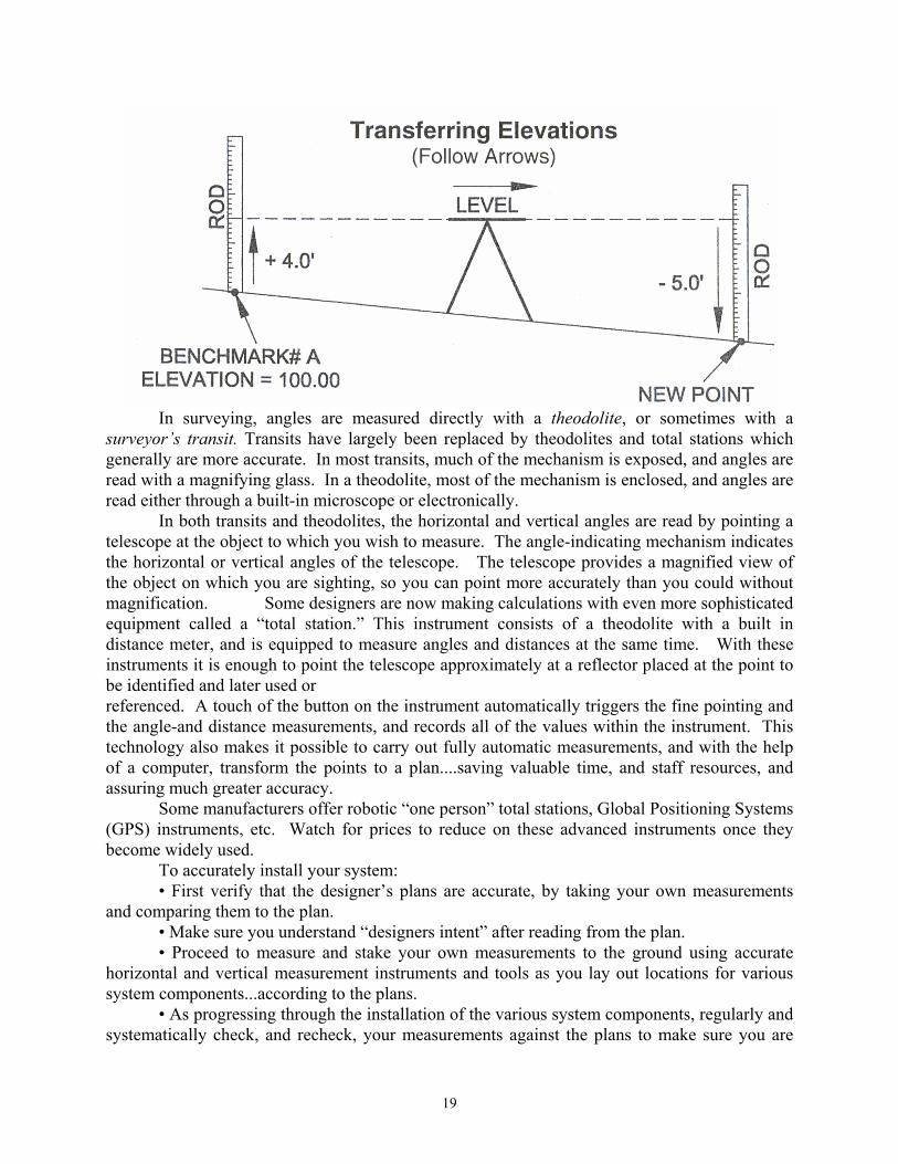
In surveying, angles are measured directly with a theodolite, or sometimes with a surveyor’s transit. Transits have largely been replaced by theodolites and total stations which generally are more accurate. In most transits, much of the mechanism is exposed, and angles are read with a magnifying glass. In a theodolite, most of the mechanism is enclosed, and angles are read either through a built-in microscope or electronically.
In both transits and theodolites, the horizontal and vertical angles are read by pointing a telescope at the object to which you wish to measure. The angle-indicating mechanism indicates the horizontal or vertical angles of the telescope. The telescope provides a magnified view of the object on which you are sighting, so you can point more accurately than you could without magnification. Some designers are now making calculations with even more sophisticated equipment called a “total station.” This instrument consists of a theodolite with a built in distance meter, and is equipped to measure angles and distances at the same time. With these instruments it is enough to point the telescope approximately at a reflector placed at the point to be identified and later used or referenced. A touch of the button on the instrument automatically triggers the fine pointing and the angle-and distance measurements, and records all of the values within the instrument. This technology also makes it possible to carry out fully automatic measurements, and with the help of a computer, transform the points to a plan....saving valuable time, and staff resources, and assuring much greater accuracy.
Some manufacturers offer robotic “one person” total stations, Global Positioning Systems (GPS) instruments, etc. Watch for prices to reduce on these advanced instruments once they become widely used.
To accurately install your system: • First verify that the designer’s plans are accurate, by taking your own measurements
and comparing them to the plan. • Make sure you understand “designers intent” after reading from the plan. • Proceed to measure and stake your own measurements to the ground using accurate
horizontal and vertical measurement instruments and tools as you lay out locations for various system components...according to the plans.
• As progressing through the installation of the various system components, regularly and systematically check, and recheck, your measurements against the plans to make sure you are
19

correct. It will save valuable time, money, help assure an okay at final inspection time, and assure a properly functioning system upon completion.
Transforming the designer’s measurements to the ground and thereby to a final installed product, is one of the most vital steps you will take in installing a septic system. Make sure you do it accurately, with quality equipment, and follow the designer’s plans.
What do you do should you find that your measurements don’t match those on the designer’s plan? Stop and call the designer. Let the designer know you would like to have a “meeting of the minds” to correct any discrepancies. In some cases your designer will be able to clarify his intent, or, in come cases he may file an amended plan. The NHDES does not allow “as built” plans.
by Kenneth Bradley, WASTE, Inc., Concord, NH
20

Choosing Appropriate Fill Sands The most important component of an effluent disposal area (the leaching portion) is the
sand used under it to raise the field to its proper design elevation. To find a supplier for sand that meets NHDES specifications may require you to check out several pits in order to obtain the right material.
Use clean, coarse, bank run sand, free of topsoil, loam or stones larger than six inches in diameter to build up the effluent disposal area. The final six inches immediately below the designed bed bottom elevation must be coarse textured, clean, septic sand with an effective grain size of .25mm to 2.0mm.
Some pits offer “washed” septic sand. Try to use it if available. Septic sand should contain no more than 5% “silt”, or “fine sand”, when a sample is passed through a #200 screen sieve. Fine sand particles or silt will clog the pore spaces between coarse sand grains and will keep effluent from perking through the sand as it is supposed to do. Consider purchasing a set of screen sieves to check the septic sand first. Sand should meet specifications under Env-Ws 1014.10 to be acceptable to the DES Regional Inspector.
Prior to loading your trucks with septic sand, pick up a handful. Does it pack into a ball when squeezed? Does it feel like beach sand or baking flour? Does it turn dusty when you throw it? It shouldn’t; it should be gritty and loose. Almost no fine particles should stick to your palms or fingers. When you wet it and rub it in your hand, it should not stain your fingers brown. Brown stains tell you it has loam in it. Loamy sand or silty sand should never be used under an effluent leaching area. If in doubt about sand quality, call your designer to check it first.
Use extreme care when placing septic sand on the prepared ground surface. First strip out all topsoil, loam, rocks, stumps, wood and leaves from the area under the side slopes, fill extensions and bed area itself during dry weather only. Do not remove the mineral soil under the topsoil horizon. Stockpile the topsoil separately on-site for later use. Scarify the mineral subsoil with the teeth of an excavator before placing the sand on it. Pay careful attention to prevent rainwater sheet flow from entering the excavated bed area. Avoid soil compaction in the prepared surface area by keeping construction equipment and trucks out. Dump the sand outside the prepared area. Cast the sand into place with an excavator or push it onto the prepared area with a small dozer keeping at least one foot of sand under the tracks at all times. No machine compacting is allowed. Adhering to these provisions will assure that the effluent disposal system you build will last a long time given proper use and maintenance.
By Jay Baas, Environmentalist III, DES Subsurface Systems Bureau, Concord, NH
21

Choosing Appropriate Septic Stone “Septic stone” is a specialized product used for constructing effluent disposal systems.
Ask for it by name when you order it from a supplier. It should always be uniformly sized, washed, clean stone aggregate free of silt, stone dust, fines or clay. Pea stone, drainage stone, rip-rap or bank run gravel is not an acceptable substitute for septic stone.
Approved septic stone shall be 1.5 inch stone within a range of .75 to 2.5 inches in diameter. Always check the stone before it is loaded onto your truck or delivered on-site. It should look and feel clean, not dusty, sandy or gritty. At the pit, make sure the loader operator scoops the stone from high in the pile, at least 3 feet up. Stone dust and other “fines” are known to settle to the bottom of the stone pile at the pit and could contaminate your stone if loaded on. Don’t make the mistake of using dirty stone. DES inspectors will reject dirty stone and require you to replace it with the right stone before granting operational approval for your system. If in doubt about stone quality, have your designer check it first.
Use care when placing septic stone on the prepared bed bottom surface. Rake and level the septic sand surface before placing stone on it. Work from outside the bed and cast the stone on with an excavator bucket directly from the truck body if possible. Place the perforated sewer pipe network in the stone at the specified design elevation as you go and level it. Do not use a bucket loader to place the stone. Do not allow trucks or equipment to drive over the prepared bed surface to dump septic stone. Always avoid compacting the in-place stone with vehicles or rubber-tired equipment. Never backfill any system without first getting written approval from a DES Regional Inspector.
After inspection and operational approval by a DES Regional Inspector, first cover the stone with either filter fabric, two inches of hay or untreated building paper as specified on the design before you backfill it. Backfill the bed and fill extensions to a depth of six to 12 inches with bank run sand and at least six inches of topsoil as top cover. Place clean loam on the side slopes to a depth of six inches and seed it as required on plans. Maximum cover over an effluent disposal field should not exceed 18 inches without adding a stack vent. Never use clay as backfill on any part of a system. Remember to stop work and call to the system designer if any changes become necessary or if you encounter a problem during the system installation. That call could save you considerable rework and time later on.
By Jay Baas, Environmentalist III, DES Subsurface Systems Bureau, Concord, NH
22

Site Work and Construction Techniques Onsite wastewater disposal systems (owds) -- “Septic Systems” -- are expected to do two
jobs: First, they must dispose of wastewater. Second, we expect them to treat wastewater so that it is returned to the groundwater safely. All construction should have these two goals firmly in mind. An understanding of the functions and aging processes will be very helpful in reaching these goals.
Our goal in this Chapter is to discuss using good construction techniques to assure successful system installation.
Planning Successful system installation begins long before the excavator arrives. It begins with
plan reading, layout, grade checking -- that is, planning the job. The very first step is to be sure you have a copy of the final approved plan, and of the
construction approval. (I prefer to not take the owner’s stamped plan into the field, as I will mark it up during construction.)
Review this plan, looking for design intent, dimensions, and key specifications. Highlight these points, or make notes or a checklist.
A very important step to make here is to contact local authorities to see if local inspections are required. I do this before bidding, or taking a job. Many town’s now require so-called “bed bottom” inspections. What they actually want to see is properly called the “basal area,” in systems that are built on fill, this area is the prepared, natural soil on which fill is to be placed: The base of the fill.
Other inspections may be called for. Check!!!
Layout Good site and system layout is essential to a successful installation. Time spent here is
paid back several times over. The leaching or disposal portions of the system is laid out, on the plan, with “tie”
dimensions to two permanent or semi-permanent points. These may (or may not) be conveniently near the system. Often the designer will use two points that are well-established, such as boundary corners or survey “hubs.” Pulling tapes through underbrush or slash can be a challenge.
Once the two given points on the plan are established on the ground, by stakes or other markers, lay out the other two corners. Almost all systems are rectangles, so it is convenient to calculate the diagonal of the rectangle. (This is a step I often do in the office, but is easily done in the field with a common calculator.)
Many “old-timers” used the 3-4-5 ratio to establish a right angle. This is: If one leg is 3 feet (or any multiple, say 3x4=12 feet) and the second side is 4 feet (or 4x4=16 feet) the diagonal is 5 feet (or 5x4=20 feet).
23

This is an example of a simple powerful tool called the Pythagorean Theorem. This says that the square of one leg of a right triangle, added to the square of the other leg, equals the square of the diagonal.
It is really simple to “solve” for the diagonal of any rectangle. I would be lost without this powerful tool! In algebra we would say that A² + B² = C² . So C = the square root of A² +B².
Say you have a simple 20'x40'; bed. 20x20 = 400; 40x40=1600, 400+1600=2000. The square root of 2000 = 44.7', rounded off.
The easy way to do this, with a cheap (or free) calculator is: First, clear everything, including memory. The best calculators for this have a “MC” key (memory clear).
Then, enter one side (a), say 20', multiply by itself and enter into memory: 20 x 20 = M+ Do this for the other side:
24

40 x 40 = M+ Then recall the memory, (should be 2000 in the sample!), and hit Square Root ( ).
(one leg = A) A x A = M+ (second leg = B) B x B = M+ (diagonal = C) MR (Memory Recall or Memory Total) Gives the diagonal.
Now, lay out the corners. Two tapes with tenths of feet on one side make this easy. These fiberglass tapes, with inches on one side and tenths on the other, are inexpensive and become valuable tools. I have “stickers” (pointed pins) on mine so I can do this alone.
With tapes at exactly the “long leg” apart, measure one short leg and the diagonal:
Then, repeat:
And check the far side. Measure twice, dig once!
Now you have these four points. Ready to dig? Not yet! When checking the plan, you found (or should have found) Design Intent (see separate
Chapter in this manual on designer’s intent). This is a two-part statement that gives first the elevation of the leaching area bottom, (the real bed bottom) and second, it’s “relationship to grade.”
25

This second is one part of what the plan is really all about. It should say that the bed is so many inches, or feet, above (or below) the original (undisturbed) ground at the high corner.
The design intent is meant to tell you the least you should raise the bed above the original ground (or, less commonly these days, the most you can dig in).
So, the next step is to check this out. Get a reading (“back sight”) on the bench mark, and figure out the height of the instrument (HI).
Then take readings on the four corners. Record these readings! The bed bottom elevation, subtracted from the height of the instrument, should be very close to the design intent. If it varies a lot (more than 6" in my book) you should call the designer.
Yes, I know you’re itching to go. Are we ready yet? I would say, not quite. Having gotten this far, I consider it good practice to establish a ”local control.”
By this I mean several things. One step is to set a personal bench mark. Figure out the correct reading (“foresight”) for the bed bottom. Then, drive a nail in a tree at this reading, and mark it “bed bottom.” It really simplifies future setups.
Even more important, in some cases, is setting “offset” stakes. If layout was a challenge, don’t go through it again. Pull tapes in a straight line to one long leg, falling outside any work area. If the slopes go 15' from the bed, say, pull 25' in a straight line to each uphill corner, and mark the stakes! Or, you could pull tapes to nearby objects and record your own tie points. All this may seem a “pain” now, but will save a lot of time, later.
Site Conditions Ready to go now? Plans in hand, planning and layout done, machinery ready...is the site
ready for you? Most importantly, is the soil ready for you? Since the natural soil must both accept wastewater and perform the final steps of treatment, you need to know this.
Soil 101, super simplified: Soil comes in three broad ranges of texture. Texture means the basic fineness or coarseness of soil. (More exactly it is the ratio of sand, silt, and clay in a soil.) Checking for soil-readiness, as well as many other construction concerns, becomes much more important as a soil becomes finer (more silty or clayey).
The test pit log should give you some clues about texture. But, I believe in checking for myself.
26

--
Sandy soils will not form a ball when squeezed, or, will form a ball that breaks very easily.
Loamy soils will form a ball that can be handled easily, when the soil is moist, but they will not “ribbon.”
Clayey soils will form a ball easily, and can be made to squeeze out into a ribbon when it is at the correct moisture.
Sandy soils can be worked at nearly any time, as they usually drain easily between the sand grains.
Loamy and clayey soils depend on structure in the soil for drainage. This is increasingly more important as the soil gets finer or more clayey. Structure (the little cracks in the soil) is easily damaged or destroyed by construction activities, especially when the soil is moist.
One test that is helpful is to determine if the soil is below the plastic limit. Take a sample, from 12" deep, and see if moisture can be squeezed from it. If not, the soil is below the plastic limit.
Prepare The Site So -- plan in hand, layout done, soil is ready -- and you’ve planned your work. Now it’s
time to work the plan. System design intent is started as “above/below original grade.” This usefully breaks
systems down into two groups - those built above ground, on, or, in fill, and those built below ground (few and far between, these days).
Disposal areas built below ground are built in sandy soils, which require few special preparation techniques. Excavation to the bed bottom elevation, and leveling the bottom, may be all that is necessary. However, sand comes in a broad range of sizes and gradations. It may be desirable to dig out 6" extra and replace this with a coarse select sand (such as concrete sand) to improve bed life. In any case, a level bed bottom is thought to be very important to bed life. You may have to call for local inspection at this time.
Raised Bed Site Preparation Most disposal areas in New Hampshire are likely to be built in fill, as raised beds. Site
preparation for these systems must focus on preparing the soil surface the basal area (often mis-called the bed bottom) -- to receive fill, and ultimately, effluent.
Construction begins with removing stumps and grubbing, followed by topsoil removal. While backhoes and bulldozers may be used, the best choice for most prep work is the hydraulic excavator. This all-purpose tool exerts less ground pressure than rubber-tired machines, and works without moving back and forth, pushing as a dozer does, thus protecting structure.
Some disagreement exists about what constitutes an appropriate amount of material removal during site prep. (Some states say none; even leaving stumps in place!) In New Hampshire, we expect to remove the topsoil layer. Some local inspectors expect to see all roots and large rocks gone. It is my belief that a trace of topsoil and a few rocks and roots, are preferable to removing subsoil, which is often far more permeable than the denser, more compact layers below. Finally, scarifying (loosening) the receiving surface with an appropriate tool - such as excavators teeth--parallel to the slope, should be accomplished. Remember local inspection!
27
Fill Placement After inspection (if necessary), it is time to place fill. At this point, two goals must be
kept in mind - and, they conflict with one another. The first goal is to protect the prepared receiving surface. This means limiting all traffic,
especially truck traffic, from the site. The second goal, in any fill placement, is compaction. If the fill is not adequately
compacted, settlement will take place. If placed on a slope, the side with more fill will settle more -- this is “differential settlement.”
On large fills, good practice would call for an overburden of additional fill -- a “surcharge” -- to be placed on the base, and left in place - for months! This is usually impractical for disposal area construction.
The appropriate technique is to dump fill to the side of the bed, and place it with a dozer. Dump on the uphill side, if on a slope. Place fill in “lifts;” 12" - 18" max. The effect of the pushing fill over the bed area to the slopes, will aid in achieving compaction.
Place fill to construct slopes, and cover slopes with topsoil. I believe this should be done before the actual disposal area is built. Often, the removed topsoil is placed side slope or downslope, and then placed back on the slope.
Fill Selection Fills for raised systems fall into several categories. The main fill is sand; by rule ‘clean
bank run sand, free of topsoil or humus, dredgings or stones greater than 6", except for the first 6" directly beneath the EDA...”, a pretty broad range of material. But this is sand, not onsite material.
Slopes may be covered with a base of heavy soil, that may underlay the topsoil. Topsoil is supposed to be appropriate for seeding. Some inspectors consider only screened topsoil as appropriate.
All other considerations aside, bed life is most affected by the quality of sand placed as the immediate receiving layer -- right under the stone or chambers. The rules specify:
Env-Ws 1021.03 Fill Material. Fill required to raise the effluent disposal area above the seasonal high ground water table or impervious substratum shall be clean bank run sand, free of topsoil or humus, dredgings, or stones more than 6 inches in any dimension, except for the first 6 inches directly beneath the EDA shall consist of:
(a) Medium to coarse textured sand, with an effective size of 0.25 to 2.0 mm, no greater than 5% passing the number 200 sieve, and no particles size larger than 3/4 inch; or
(b) Materials meeting the ASTM C-33 specification.
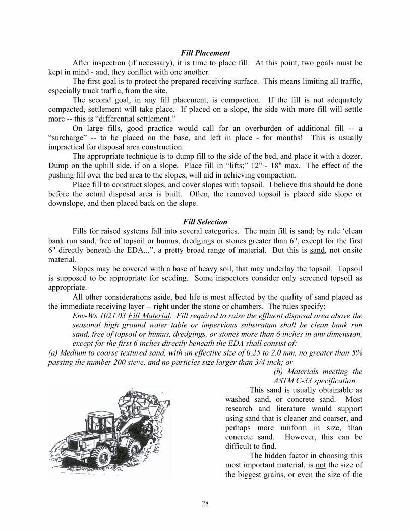
This sand is usually obtainable as washed sand, or concrete sand. Most research and literature would support using sand that is cleaner and coarser, and perhaps more uniform in size, than concrete sand. However, this can be difficult to find.
The hidden factor in choosing this most important material, is not the size of the biggest grains, or even the size of the
28
average grains. It is the size - and amount - of the smallest grains. Why is that? The small grains fill the spaces between the big grains. The gaps are easily bridged by
clogging slimes in the biomat. Bed life can be dramatically shortened. Sand can be checked, in the field by rubbing a moistened sample in your palm. There
should be little residue filling the creases in your skin. Any sand sold as concrete sand may have been tested. For larger jobs, or, where higher-strength wastewater may be encountered, submitting sand sample to a lab for sieve analysis may be desirable.
Install Disposal Area Leach Beds. Until the mid to late 1980's, the majority of disposal areas in New
Hampshire were stone - and - pipe leach beds, with concrete chambers as the main option. Since then, an increasing number of systems have been installed with “proprietary” systems - plastic chambers, large diameter pipes and leaching modules. When space, or fill costs, don’t dictate otherwise, leach beds can be a good alternative - a simple, robust technology.
As discussed before, the selection of the immediate receiving surface is very important. This can’t be emphasized enough. Many systems installed in New Hampshire were placed on whatever sand was available, cheap, and nearby. Failure examination of these systems indicates that the clogging mat was very thin. This is typical in fine-textured sands. Many of these failures occurred in less than ten years.
Many techniques may be used to create the leaching surface. In rule, and on many plans, this is now called the “Effluent Disposal Area” (EDA), or the “bed bottom.” The whole system is now an Effluent Disposal System (EDS). My preference is to slightly overfill the bed bottom, while filling and constructing slopes. With slopes complete and topsoil in place, I will dig out the bed area 6" below the EDS elevation, then place the select sand to the elevation of the bed, and level carefully. This sand will also form the sides of the bed. All this is done with an excavator.
Place the D-Box and carefully level. I find that the “mini” boxes don’t stay level, and prefer a standard size. Plastic D-Boxes are often best placed on a patio tile or other concrete slab.
Placing stone and pipe, again, may be done in a number of ways. In the old days, dumping the stone into the bed and leveling with a dozer, then hand-digging pipes into the stone, was commonly done. Others would dump the stone to the side and cart it in, a bucket at a time. The excavator has changed all that.
After setting the D-Box, lay out the pipe network and connect it up. Support the pipes on short pieces of 4" pipe (or other supports). A good way to use scrap! The excavator can scoop stone directly from the truck and carefully place it over the pipes. Once the pipes are filled to the top, raise the pipes using a shovel and laser, to the exact elevation of the outlet of the D-box. (I usually have the pipes just slightly lower, say 1/8" - so that flow out of the D-box is enhanced.) It is best to do this progressively - bring lines up nearly to the grade, then, finish them to the exact elevation. Once level, add stone to cover lines. With skilled people, this is a quick and nearly labor-free operation. Really!
With the bed in place, (and other components) inspection time is at hand. After state (and local, if required) inspections, backfill follows. A small dozer, or the
excavator may do this. A note on covering the stone: These days, filter fabric is often chosen. It is tough and permanent.
29
Chambers. Concrete chambers have been a successful alternative to leach beds for over 30 years in New Hampshire. They can be driven over (H-20 units) and can be reused. In residential situations, they take up less space, and may save substantial fill. (And, you get a candy cane - always a hit with homeowners.)
The same considerations for fill placement, slopes, and EDA (bed bottom) construction for stone beds apply here. It is even more important to assure levelness of the EDA, as the chambers must be level. Take extra time to insure levelness.
You may have to prepare an access for delivery truck. Alternatively, the excavator may set the units. Be careful!! These rigs are heavy, and can hurt if you are not!
Rule allows the sides of concrete chambers to be covered with filter fabric. I consider that adding 12" of stone, in the “old” way, a valuable addition for low cost. This small strip of stone may add 25% to 50% of additional leaching surface and add significant life to the system, for very low dollars.
Plastic Chambers. Plastic leaching galleries or chambers came into wide use in the 1980's. They were light and easy to install. Experience has revealed a few shortcomings to watch out for, however.
The same considerations in construction of the bed/EDA, above, apply. However, experience has shown that many plastic chamber systems were either crushed, or driven into the sand below - or both. Often, there was nearly no free space in the chambers, when examined at failure.
Much of this damage happened at back fill. As well, settlement into the sand below may have occurred. One must be very careful in back filling these units. Placing the fill with an excavator may be the best technique - spreading fill with a small dozer keeping tracks perpendicular to the units may also be accomplished. Maintain at least 12" cover, tracks to units.
Other Proprietary Units. The growing use of fabric-based systems -- large diameter, fabric wrapped pipes and cuspated plastic/fabric modules -- presents new challenges to the installer. Careful selection of fill sands, effluent receiving sands, and placement techniques become increasingly important. The foot print of these systems is often 1/4 that of a stone bed. All factors - from layout, basal area preparation, fill placement through backfill --are more critical.
These system types are laid out in a variety of distribution patterns. As well, they may be laid to follow the contour, and even may curve, to follow contours. The imaginative installer will need to find ways to install these various systems while maintaining the integrity of the natural receiving soil, and achieving reasonable fill compaction.
Since many of these systems are fed from a D-box in parallel fashion, with the D-box located upslope, careful placement and assurance of D-box levelness is extra critical. Be especially careful during backfill. Numerous apparent failures have been traced to unequal distribution, with small parts of the disposal area getting all the load, and failing locally. Out-of-level D-boxes, and construction damage, are usually to blame.
30
Septic Tanks Installing the tank (or tanks) is not often thought of as difficult -- dig the hole, drop it in,
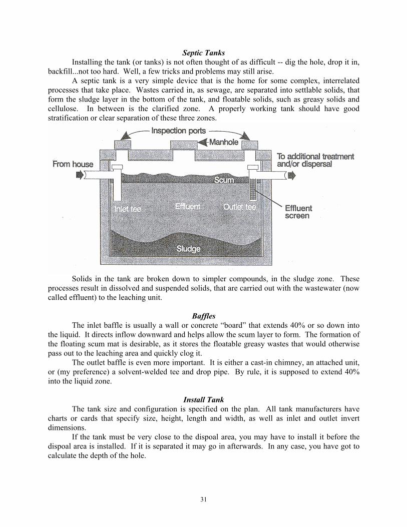
backfill...not too hard. Well, a few tricks and problems may still arise. A septic tank is a very simple device that is the home for some complex, interrelated
processes that take place. Wastes carried in, as sewage, are separated into settlable solids, that form the sludge layer in the bottom of the tank, and floatable solids, such as greasy solids and cellulose. In between is the clarified zone. A properly working tank should have good stratification or clear separation of these three zones.
Solids in the tank are broken down to simpler compounds, in the sludge zone. These processes result in dissolved and suspended solids, that are carried out with the wastewater (now called effluent) to the leaching unit.
Baffles The inlet baffle is usually a wall or concrete “board” that extends 40% or so down into
the liquid. It directs inflow downward and helps allow the scum layer to form. The formation of the floating scum mat is desirable, as it stores the floatable greasy wastes that would otherwise pass out to the leaching area and quickly clog it.
The outlet baffle is even more important. It is either a cast-in chimney, an attached unit, or (my preference) a solvent-welded tee and drop pipe. By rule, it is supposed to extend 40% into the liquid zone.
Install Tank The tank size and configuration is specified on the plan. All tank manufacturers have
charts or cards that specify size, height, length and width, as well as inlet and outlet invert dimensions.
If the tank must be very close to the dispoal area, you may have to install it before the dispoal area is installed. If it is separated it may go in afterwards. In any case, you have got to calculate the depth of the hole.
31
The plan should specify the D-box inlet elevation. Usually, one-tenth of a foot is assumed to be the difference between inlet and outlet elevations. Not all D-boxes have an 0.1 foot drop! Check.
From this elevation, add the pipe run, 0.1 feet per ten foot length. Then, subtract the outlet invert dimension. While all this may be done from the called-out elevations on the plan, it is much easier to do if the D-box is in place. If you have to move the tank, and the pipe run is a different length, you will have to do this anyway.
These calculations may be made several ways. If you use the called-out elevations, simply subtract the tank’s outlet dimension from the outlet invert elevation. You may have to convert to decimal (tenths of feet) here. Say, the outlet is 45" up, divide 45" by 12" (45÷12) to get 3.75. Subtract 3.75 from the outlet elevation to get tank hole bottom.
More commonly, I’ll work from the D-box, and use foresight readings. This is especially true if the tank is not right where the plan called out.
Say I have a reading (foresight) of 4.2 at the D-box inlet invert, and the tank will be 25' away. The effluent line must gain 1/8" per foot in 25'. This is 1% pitch or 0.1' per ten feet - 25' x 1% = 25' x .01 = .25'.
Whatever the effluent length is, in feet, multiply by .01 to get the drop in tenths of feet. You will note that I don’t use inches. This is not just because almost all plans use tenths
of feet, but also because tenths are easier. Calculators love tenths! Using foresights requires working “backwards.” If you’re moving upslope (up the pipe),
you must subtract the readings. In my example, my D-box reading was 4.2' and I gained 0.25' to the tank. This would be
3.95' (4.2'-0.25') if the tank outlet invert was 45", 45" ÷ 12" = 3.75'. The tank hole bottom would be 3.75' deeper, so add: 3.95 + 3.75= 7.70. This is the deepest the tank hole can go.
I will usually add a tenth or two, for comfort here, unless pitches are critical. (This really means shortening the stick or reading - say, to 7.50). But, I will also look at grades -- I don’t particularly like tanks buried 2 or 3 feet, so I’ll raise the tank, if I can, to end up with 6" to 12" of cover. Remember, somebody has to dig these units up to pump them!
A little sand on the bottom of the tank hole can make leveling the hole much easier. If the soil is rocky or is fine textured, (silty or clayey) or frozen sand, backfill is very desirable.
Compaction of the tank back fill -- where the pipes will be laid, in and out, is important --many later service calls are for settled, crushed or separated pipes. Settlement of uncompacted backfill is often the cause. I will place fill with a hoe or excavator, and carefully press it down. Don’t break the tank!
Pipes should enter the tank at nearly a perpendicular to the tank. It is good practice to use SDR 35 or stronger for the effluent line. 90 bends are not usually allowed in this line -- use 2-45 bends to make a 90 .
Tanks usually have cast-in seals, so that the installer only has to push the pipe in. Occasionally, it must be “grouted.” Use a “non-shrink” grout. Waterplug is one good choice. I use structural skin (“blockbond”), a mix of a good mortar with fiberglass. Common premixed mortars are often of inferior quality.
The sewer pipe, to the home, is usually Schedule 40 PVC, but may be SDR26. The section through the wall must be at least schedule 40, or cast iron. A convenient way to transition between pipe types is the rubber connector, such as a “Fernco” coupler. This pipe run, in 4", must be 1/4" per foot. This is the same as 2%, or 0.2' per ten feet.
32
Pipes should be carefully bedded. Bedding the pipe in sand is an easy way to protect them in “cross-country” runs. Be especially careful to compact bedding under and beside the pipes. Pipes tend to crush or deform when the lower part of the pipe can spread outward. The bottom half of the pipe is called the “haunching” area. If the pipe must go under a drive, consider bedding the pipe in pea stone or 3/4" stone.
Under drives, rule calls for lines to be a minumum of SDR 26 or Schedule 40. Rule calls for 48" of cover, or for the line to be insulated. Closed cell foam insulation, at least 1" thick, laid on a level sand cover, works well. Backfill with sand, over the insulation.
Consider the homeowner/pumper, in covering the tank. You’ll not win any fans with a tank buried 2' or more, with rocky soil. Rule calls for access within 6" of grade. I prefer access to grade, but most homeowners don’t care for concrete covers in their lawn.
Many new tanks come without an outlet baffle, to facilitate various configurations. (Some even now come without inlet baffles.) This allows for easy installation of effluent filters.
If the tank requires an outlet baffle, you must use PVC pipe, if you are solvent-welding (“gluing”). Common sewer and drain pipe is usually polyethlene (PE). This pipe is usually black inside, and is not suitable to solvent-weld. SDR 35, 26 and 21, or schedule 40, are PVC; some sewer and drain is still PVC. SDR stands for standard dimention ratio. This is the ratio of wall thickness to pipe diameter. The lower the number, the thicker the pipe. Up to 4" diameter, SDR pipes are the same outside diameter as sewer and drain (S & D).
If you need to install an outlet baffle, measure from the bottom of the tank to the outlet invert (the bottom of the pipe). Multiply by 0.4. Example -- if the measurement is 45", 0.4 x 45" = 18". This is the length of the outlet baffle drop pipe. If it’s not an even amount, round to the nearest inch.
Effluent Filters Effluent filters are a common requirement found on many plans today. They trap some
solids and may provide an additional measure of treatment. As they do this, they clog. Small filters may clog in one year or less, causing a backup, when located in a primary tank. A better choice is to locate the filter in a second compartment of a two-compartment tank, or in a second tank. Filter clogging is greatly reduced in this scenario. I also find it helpful to tie a line, such as parachute cord, to the filter. In the case of a clog, the unit may be submerged. This line will make removal much easier.
Inspections and Approvals The inspection performed by the regional inspector for the NHDES, is basically an
inspection to assure that the installation conforms to the plan, and that site conditions reported on the plan match observed site conditions.
All the components of the system should be in place and visible when you call the inspector, including sewer pipe to house; tank or tanks; effluent line; disposal area components; slopes and topsoil; etc. Don’t forget vents and baffles.
If anything differs from the plan in location, amended plans must be on site for the state inspector. Place 3 stamped, amended plans, in a sealed baggie, in the D-box, or other secure location. Let the inspector know that they are there.
33

What Can Be Amended? It is easier to say what cannot be amended. The heart of the approval is the location and
elevation of the dispoal unit. The leaching unit can’t be moved up, down or sideways from the plan.
Anything else -- house, tank, well, even the D-box within the bed, can be moved. Be careful -- all moves must meet setback requirements. This means both state and local setbacks. It is best to have the designer okay any moves.
If the town you are working in requires local approval of plans before they go to the state, any amended plans will also have to be reviewed and stamped locally, before the state inspector will review and approve the amended plans at inspection. This should have been checked out way back in the pre-planning phase. Some local reviews of plans are because the town has more stringent requirements than the state. Often, these requirements are for greater setbacks. These setback requirements are usually in the zoning regulations. These regulations are not waiverable! Check carefully, and check again, to be sure about local requirements!
A Note On Wells Rule calls for the protective radius of the well to be contained within the lot, or located
on other undevelopable land -- such as road right-of-way, surface water, etc. However, the owner may execute a “release form for protective well radii.” This may be done for the original approval, on the plan, or for the operational approval. This release must be recorded at the county registry of deeds. It will form part of the approval for construction/operation. The designer can help with this.
By Thomas Canfield, Canfield Earth Construction, Rochester, NH
34

Safety on The Construction Site
Assuring the safety of your workers, the property owner, your equipment and you are one of the most important responsibilities you have as the installer of a septic system, or for that matter, while doing any excavation work. SAFETY FIRST!
This Chapter has been broken down into several sections as noted by the subheading. The appendix of this manual also includes several other items which may prove helpful.
Dig Safe New Hampshire state law--expanded effective January 1, 2002--requires a homeowner,
contractor or excavator to notify the appropriate utility companies three days (72 hours) before excavating so they can mark their underground facilities.
You are required to do this if you plan to dig within 100 feet of an underground facility on:
• private property (effective Jan. 1, 2002) • public way (roads) • rights-of-way • on easements • in public streets • or other public place To make it easier for excavators, the following utilities are required to join “Dig Safe”:
gas, electric, telecommunications, cable television and public water companies. Municipal water, sewer and drainage ARE EXEMPT. When planning to dig in any of the above areas, which could affect any of these utilities, here’s one easy number to call toll-free:
1-888-DIG-SAFE, that’s 1-888-344-7233 (You may also notify Dig Safe at 781-721-0047, or by its web site at www.digsafe.com.
However, if using these two alternate methods, allow an extra 24 hours)
Many utilities located in New Hampshire utilize privately owned locating services such as On Target to locate their underground utilities, vs. the utility itself. One such company is Contract Locating Company, a private company started in 1994 that now employs more than 150 locators throughout New England. OT is not Dig Safe.
Once a call comes into the Dig Safe call center, information is dispatched to locators in the field via laptop computers to cover given areas. Most emergency calls are responded to within one hour to one and one-half hours (if a delay of more than one and one-half hour is expected, the contractor will be notified).
Before the OT contractor arrives following your request for utility markings, as contractor you must pre-mark the construction area, identifying the perimeter of the proposed site using the color white. No pre-mark is required on any continuous excavation more than 100 feet in length. OT locates and marks utility owned facilities to the point of demarcation.
35
Here’s the color scheme used: • For electric flag color is red • For communications flag color is orange • For gas, steam or oil, flag color is yellow • For water, flag color is blue The colored flags may also be marked and tagged using such phrases as “no electricity
below,” “fiber optic below,” “electricity in area, not located,” etc. White tip stakes are to show location of the dig area, sign post, tree planting--at
beginning and end of trench. White and blue tipped stakes are for water repair. The “Dig Safe” law calls for an excavator to use non-mechanized equipment when
digging within 18 inches of a marked underground utility. If you damage a utility line, do NOT call Dig Safe first!....contact the affected utility
company directly. Do not attempt repairs to the damaged facility! Wait for utility company to repair line before backfilling.
Your “ticket” for digging issued by Dig Safe will be good 30 days from time of notification. One can renew for another 30 days up to the 27th day of the first permit time.
Respect the law and dig safely. It will be your responsibility if you don’t heed markings. In addition, it should be noted civil penalties have increased to $5,000.
One additional suggestion: Have a camera on hand and take a picture of the utility markings once they are completed. Once you start digging, your only protection is a picture showing the offset stakes.
(For a complete copy of the N. H. Dig Safe Law and Rules, visit Dig Safe on line at www.digsafe.com, or call 1-888-DIG-SAFE. For questions regarding the N. H. Dig Safe Law, contact the New Hampshire Public Utilities Commission at 1-888-397-5444, or (603) 271-6022.)
Construction Site Safety Now that Dig Safe has given us the green light and told us theoretically where utility
lines are located and are to be avoided, the work should be able to start safely. But, what other safety steps can we actually think of before we start digging?
It starts by keeping unnecessary people and equipment away from any work area, by properly marking and taping off the area. Only experienced and trained personnel should be within the work area and operating any equipment. By planning your work site in advance you should be able to minimize any unnecessary movement of equipment once work starts.
Now that we have a complete set of plans, let’s obtain and maintain a log book to: --log the conditions of the day, --record who was at the job site, --record various approval numbers that are obtained (Dig Safe, DES, DOT, etc.), --record the fact that all vehicle inspection reports have been done, --record the fact you made sure you have on your person a laser operator training and
qualification card, and if you are using a red beam laser such as for laying septic pipe, you made certain a “Caution Danger Laser” placard was posted visibly in the area.
All gas cans used on a site should have a UL approved label, whether made of plastic or steel, and have a spark resistant cone in use.
DEALING WITH TRAFFIC: Unless you are working in a quiet subdivision off the traveled way, traffic can become a real hurdle during the construction day. Two words come to
36

mind when dealing with traffic--visibility and separation. We want to become as visible as possible to the motoring public, and separate ourselves from that motoring public. Signs and barricades which warn the public of approaching construction up ahead should be erected. In general, a four-foot diamond shaped sign should be used for traffic more than 45 miles per hour and a three-foot diamond shaped sign of highly visible color should be used if traffic speeds are less than 45 miles per hour.
All traffic controls must conform to the MUTED (Manual on Uniform Traffic Control Devices) published by the U. S. Dept. of Transportation, Federal Highway Administration. Once you have laid out your signage warning motorists of construction ahead, other components of a Work Safety Zone need to be put in place, including signs, transition area, a taper, a buffer, work area and termination. Once signs are laid out, drive the pattern to make sure there is an escape route for the motoring public.
Traffic cones should be used to channel traffic flow around the construction site. These cones must be either 18" or 28" in height, with reflective bands on them when any nighttime work is anticipated.
Again, we have not started digging yet. We must observe any overhead wires, and exercise care to make sure there is provision to prevent any piece of equipment from coming within 10 feet of any overhead wire.
PERSONAL PROTECTIVE EQUIPMENT AND OTHER PRECAUTIONS: Care should be given to all operators and crew on your job site, requiring the wearing of hard hats, safety glasses, steel-toed shoes, hearing protection, gloves and any type of Tyvek fire suit or other protective clothing if working around hazardous sites. If you are a subcontractor on a multi-employer work site, you should obtain the various contractors’ Material Safety Data Sheets, directions to the fire station, police, hospital, etc., as well as their phone numbers.
When using any lifting equipment such as chains or slings, make sure the chains are tagged and the slings and chains are inspected to have the proper weight restriction tags attached.
If you are burying PVC pipe, it is a good idea to install a tracer wire, such as the gas companies use so that plastic pipe can be located in future years.
Inspect all extension cords for fraying and any breaks, and obtain a Ground Fault Circuit Interrupter (GFCI) if you are plugging any electrical appliance such as a drill or saw into an extension cord. Always observe explosion-proof and intrinsically safe work habits for the use of your equipment, and be sure to follow lock-out/tag-out procedures.
Are we ready to dig? Almost. After we have recorded all this information in our log book, have the traffic under control, have gathered all the required MSDS sheets that we and our subcontractor might be using (so that we know what safety precautions to take should there be an accident), then we ought to be ready to begin excavation.
Some Trenching and Excavation Rules to Live By When trenching and excavating, whenever any person is going into a hole, there must be
a Competent Person on site. According to 1926 SubPart P of the OSHA manual, a Competent Person is defined as “one who is capable of identifying existing and predictable hazards in the surroundings, or working conditions that are unsanitary, hazardous or dangerous to employees, and who has authorization to take prompt corrective measures to correct them.” In this way a competent person could be an operator, laborer, or any other person who has received training and who has authorization to take immediate action.
37

Prior to a person climbing into an excavation greater than four-feet where one suspects a hazardous atmosphere could be present, atmospheric tests for hazardous atmosphere must be taken and continually monitored while a person is in the hole. If the hole is greater than five feet, or if there is a possibility of a cave-in, the contractor must slope, shore, or use a trench box to protect any worker in the excavation. The contractor is also required to provide a ladder as a means of access and place enough ladders in a trench so that the employee does not have to travel further than 25-feet to gain access to a ladder.
All spoils piles and any other obstacles (such as the next piece of pipe, compactor, etc.) must be kept at least two-feet from the edge of the trench. Should the top of the trench box be dropped below grade, you need to measure down 18 inches on the box, and slope at 1 1/2 :1 slope back to the original grade to prevent any rolling materials falling into the box.
In dry soil it is allowable to bench up a trench box up to the maximum of two feet off the bottom. Once the trench box is in the ground, the contractor should add a bucket full of soil on either side of the trench box to protect against lateral movement of that trench box.
According to the Competent Persons Guidelines, soils can be classified as solid rock, or A, B, and C soils. “A” soils are those stiff cohesive soils such as clay. “B” soils are the sandy hardpans that we may encounter, and “C” soils are what we are usually in--sands or gravels previously excavated or saturated soils. When using a trench box, the Competent Person must make sure that everyone is familiar with the tabulated data for a trench box which denotes a depth to which that manufactured box can be safely installed to protect from cave in.
A registered professional engineer must stamp the tabulated data for easy cross-reference. Steel plates can also be used on large jobs, but you must provide test certificates to make sure that they provide an H-20 loading for any equipment that may travel over them.
CONFINED SPACE ENTRY: We also must think of confined space and create awareness of hazards associated with confined space entry. A confined space is an enclosed space, having the following characteristics:
1. Limited or restricted means of entry or exit. 2. Large enough for a person to enter. 3. Not designed for continuous employee occupancy. 4. A confined space environment requiring a permit would include one or more of the
following characteristics: a) a known potential to contain a hazardous atmosphere; b) potential for engulfment or entrapment; c) internal configuration that could trap or asphyxiate the entrant; d) a floor that slopes down and tapers to a smaller cross section; and e) contains any other recognized serious safety or health hazards.
Confined spaces may include manholes, sewers, septic tanks, culverts, pump stations, etc., and pits over four feet deep.
Although this chapter is not designed to scare anyone, it is designed to create an awareness of the hazards that can exist in and around our project sites.
Site inspectors, evaluators, permitted designers, and engineers must take care when evaluating test pits. Think before you jump into a test pit using a Munsell book and pocket knife that an accident could be looming.
Many accidents happen every year in New Hampshire in confined spaces, be they due to a fall, oxygen deficiency, toxic vapor, or exposure to an explosion. Never trust your senses to determine if the air in a confined space is safe. You cannot see or smell many toxic gases and
38
vapors, nor can you determine the level of oxygen present, which should be between 19.5 and 21.5 percent.
When testing a confined space, remember that gases have different specific gravities or weights. Examples: methane is lighter than air; carbon monoxide has the same specific gravity as air; and hydrogen sulfide is heavier than air, and therefore settles to the bottom of a confined space.
You may be required to use a rescue retrieval tripod, gas monitor, and a blower. If there is still a presence of a toxic atmosphere, one would have to use an SCBA (self contained breathing apparatus) prior to entering a hole and let’s not forget the importance of working on the buddy system.
WORKING ABOVE GROUND? Remember that anytime we are walking on a surface more than six feet off the ground, we should be mindful of fall protection as required by the OSHA Standard. Remember that body belts were outlawed in January 1998, and any fall protection requires a full body harness with a shock absorbing lanyard attached. There are also numerous Construction Standards for stairways, ladders and scaffolding, which will not be covered in this text.
Whether we are installing a septic tank, working in a large construction site, or just repairing a leaching field, we all must be mindful of safety.
by Kenneth Bradley, WASTE, Inc., Concord, NH
39
Glossary of Terms
BIOMAT: the bacterial layer that forms between the bottom of the EDS and the sand fill or receiving layer which treats and purifies the sewage effluent.
BLACK WATER: all residential wastewater including toilet waste.
CESSPOOL: an underground pit into which raw sewage or untreated wastes are discharged and from which the liquid seeps or leaches into the surrounding soil, no longer a viable option for sewage disposal in New Hampshire.
CHAMBER SYSTEM: an effluent disposal system constructed of preformed, interconnected, open bottom leaching units providing effluent storage space and mechanical support for the soil overburden.
CONSTRUCTION APPROVAL: written approval for construction of a planned or proposed sewage disposal systems under RSA 485-A:32, I.
DESIGN INTENT: a statement of the actual bed bottom elevation of the EDA in relation to an established reference elevation on site, usually the highest original grade contour elevation under the effluent disposal system.
DISTRIBUTION BOX or D-BOX: a small concrete or plastic box from which all pipes lead to disperse equal amounts of effluent throughout a leach field. The D-box serves as a >mail box' for written communications between the DES Regional Inspector and the system installer. Check it often to see when or if you can cover a system.
DO NOT BACKFILL (DNBF): a written inspection report issued by the DES Regional Inspector which prohibits the installer from covering an effluent disposal system before correcting items listed on the DNBF form. The DES Regional Inspector places the DNBF form in the distribution box for the convenience of the installer.
DRY WELL: a sewage disposal area constructed as a covered, underground pit with open-jointed lining, surrounded with septic stone into which settled or other treated wastes are discharged for final disposal into the surrounding soil.
EFFLUENT: liquid sewage which overflows or flows out from a septic tank.
EFFLUENT DISPOSAL AREA or "EDA": a sewage disposal area designed for the final disposal of septic tank effluent.
-40-

EFFLUENT DISPOSAL SYSTEM or "EDS": all the components used to convey and/or treat effluent, including all methods used to distribute effluent into the EDA.
FAILURE: the condition produced when a subsurface sewage or waste disposal system does not properly contain or treat sewage or causes or threatens to cause the discharge of sewage on the ground surface or into adjacent surface or groundwaters.
GREY WATER: residential wastewater that does not include toilet waste.
INVERT ELEVATION: the control elevation measured at the bottom of a pipe.
INSPECTION: means an overview by the department of the effluent disposal system to ensure that the installed system is in compliance with the approved plans and specifications.
MOTTLES: spots of contrasting color in a soil horizon that indicate the seasonal high water table.
OPERATIONAL APPROVAL: written approval to cover and use or operate the constructed sewage disposal system, which is issued only after inspection by an authorized agent of the department. Operational Approval forms are placed in the d-box to inform the installer the system may be covered and backfilled.
PERCOLATION TEST (Perc test): a test hole dug to measure the rate of absorption of water into the soil under partially controlled conditions. The results of the perc test are expressed in the number of minutes it takes water to drop one inch in the hole.
SEASONAL HIGH WATER TABLE: the highest in-ground elevation to which the water table may rise during the wettest season of the year as evidenced by mottles.
SEPTIC DESIGN: a set of plans prepared by a licensed septic system designer, approved by the Dept. of Environmental Services, used to construct a septic system. A septic design contains specific information about site topography, lot lines, soil conditions, a perc test, test pit, water supply and subdivision status.
TEST PIT: a hole dug in the soil with a backhoe or excavator to determine the soil characteristics and profile description. Only a licensed septic system designer may inspect a test pit to determine the seasonal high water table for system replacement or design purposes.
Remember that this is a partial list of definitions will need to know. Other definitions relating to effluent disposal systems can be found in the manual entitled, "Subdivision and Individual Sewage Disposal System Design Rules" published in August 1999.
by Jay Baas, Environmentalist III, DES Subsurface Systems Bureau, Concord, NH
-41-

Some of the State Laws Affecting Design and Installation of Sewage Disposal Systems
485-A:29 Submission and Approval of Plans I. Any person proposing either to subdivide
land, except as provided in RSA 485-A:33, or to construct a sewage or waste disposal system, shall submit 2 copies of such locally approved plans as are required by the local planning board or other local body having authority for the approval of any such subdivision of land, which is subject to department approval, and 2 copies of plans and specifications for any sewage or waste disposal systems which will be constructed on any subdivision or lot for approval in accordance with the requirements of the department as provided in this paragraph. In the event that such subdivision plans which receive final local approval differ from the plans which are reviewed by the department, the person proposing the subdivision shall resubmit those plans to the department for re-approval. The planning board or other local body having final local approval authority shall submit one copy of such plans which receive final local approval to the department for informational purposes with 30 days of granting such final approval. The department shall adopt rules, pursuant to RSA 541-A, relative to the submission of plans and specifications as necessary to effect the purposes of this subdivision. The rules shall specify when and where the plans and specifications are to be submitted, what details, data and information are to be contained in the plans and specifications, what tests are to be required, what standard, guidelines, procedures, and criteria are to be applied and followed in constructing any sewage or waste disposal system, and other related matters. The rules shall also establish the methodology and review process for approval of innovative/alternative wastewater treatment systems and for approval of a plan for operation, maintenance, and financial responsibility for such operations. For any part or parts of the subdivisions where construction or
and Specifications. waste disposal is not contemplated, only the lot lines, property boundaries drawn to scale, and general soil and related data shall be required. The constructed sewage or waste disposal systems shall be in strict accordance with approved plans, and the facilities shall not be covered or placed in operation without final inspection and approval by an authorized agent of the department. All inspections by the department shall be accomplished within 7 business days after receipt of written notification from the builder that the system is ready for inspection. Plans and specifications need not be submitted for subdivision approval for subdivisions consisting of the division of a tract or parcel of land exclusively in lots of 5 or more acres in area. The presence of hydric soils on lots of 5 or more acres in area shall be insufficient, without additional supporting data, to classify these lots as wetlands, or to make such lots unsuitable for sewage or waste disposal systems designed for poorly drained soils. This exemption in no way relieves any person from responsibility for obtaining approval under this chapter for construction of individual or other sewage or waste disposal systems or both in any exempted lots. In such cases, it shall be the responsibility of the sub-divider to provide to the lot purchasers satisfactory assurance as the purchasers may require at the time of sale that lots sold shall be adequate to support individual sewage or waste disposal systems or both in accordance with rules adopted by the department and the requirements of this subdivision.
II. Permitted designers of subsurface sewage disposal systems shall obtain the registry of deeds volume and page numbers for each lot that relates to the septic system application and provide them to the department. The department shall develop and approve an outline of brief instructions for the
-42-
periodic maintenance, care and proper usage of waste disposal systems, including a warning of the potential public health hazard and pollution of public and private water supplies and surface water of the state from improperly maintained sewage and waste disposal systems.
485-A:30 Fees I. Any person submitting plans and
specifications for a subdivision of land shall pay to the department a fee of $80 per lot. Said fee shall be for reviewing such plans and specifications and making site inspections. Any person submitting plans and specifications for sewage or waste disposal systems shall pay to the department a fee of $80 for each system. Said fee shall be for reviewing such plans and specifications, making site inspections, and for the administration of sludge and septage management programs. The fees required by this paragraph shall be paid at the time said plans and specifications are submitted and shall be deposited with the treasurer as unrestricted revenue. For the purposes of this paragraph, the term Αlot≅ shall not include tent sites or travel trailer sites in recreational parks which are operated on a seasonal basis for not more than 9 months per year.
I-a. In addition to fees required under paragraph I, any person submitting plans and specifications for sewage or waste disposal system shall pay to the department a fee of $10 for each system. Said fee shall be for supporting a general-funded position at the department to advocate for and implement long-term septage disposal solutions in partnership with New Hampshire municipalities. The fees required by this paragraph shall be paid at the time said plans and specifications are submitted and shall be deposited with the state treasurer as unrestricted revenue.
II. [Repealed.] III. Any persons submitting plans and
specifications as a re-submission for re-approval (b) Encroachment waiver requests shall appear
on the plans. No application which includes any request for an encroachment waiver shall be accepted by the department unless the application includes a copy of the notice, a list of the names and addresses of the abutters to whom the notice
of such shall not be required to pay any additional fee under RSA 485-A:30, I or I-a if changes to such plans and specifications would not constitute a new subdivision under the provisions of RSA 485-A:2, XIII.
485-A:30-a Notice Requirements; Encroachment Waivers.
I. (a) Any person intending to submit an application for approval of a sewage or waste disposal system, which application will include a request for an encroachment waiver, shall notify the local code enforcement officer or other appropriate designated authority and all abutters as defined in RSA 672:3 that the person intends to file the application. Such notification shall include:
(1) The name and address of the property owner.
(2) Identification of the property for which an encroachment waiver is being requested, including tax map and lot numbers.
(3) Names of abutters, together with applicable tax map and lot numbers.
(4) A description of the specific waivers being requested.
(5) A reasonable facsimile of the plan. (6) Identification of any local code or
ordinance for which a waiver, variance or exception is required, and whether such waiver, variance or exception has been obtained.
(7) Notice that the department is required by law to act on the application within 15 working days of receipt of the application, and that objections to the proposed encroachment waiver may be submitted to the department during the review process or by filing a motion for reconsideration of the decision with the department within 20 days of the department=s decision on the application.
was mailed, and a statement signed by the applicant or property owner certifying that the notices were sent by certified mail to the abutters listed.
II. No construction permit shall be issued for a septic system until the department has received a
-43-

copy of the recorded notice showing that all easements and encroachment waivers associated with the application have been recorded by the property owner in the registry of deeds.
485-A:30-b Protective Well Radii I. All lots, including lots created prior to
August 20, 1989, shall be subject to the following conditions:
(a) Rules adopted under this section concerning such lots shall include provisions allowing abutting lot owners to overlap their respective well radii for their mutual benefit and provisions allowing well radii to extend over property lines onto state and locally-mandated property line setbacks, recorded easements, or land which is permanently dedicated to a use which precludes development.
(b) For private wells serving commercial buildings, the entire protective well radius shall be maintained on one or more of the following: on-lot, on a recorded easement, or land which is permanently dedicated to a use which precludes development, or on state and locally-mandated property line setbacks. For the purposes of this section, the term Αcommercial building≅ shall not include a residence which is also used for commercial purposes unless the total water withdrawal exceeds 600 gallons per day.
(c) For private wells serving buildings other than commercial buildings, if the protective well radius cannot be wholly maintained on an existing lot of record due to the size or other physical
(g) When, for reasons of the condition of the lot or the placement of buildings thereon, the well cannot be installed as shown on the approved plan, the water well contractor shall advise and consult with the property owner, or the property owner=s agent, on the best possible alternative location, considering distance to property boundaries and to the sewage or waste disposal system. Using a standard release form prepared by the department, the water well contractor shall alert the owner to the consequences of the alternate installation, including the potential loss of the protection of any portion of the radius which extends over the property line. The owner, or the owner=s agent, may defer to the designer of the sewage or waste
characteristics of the lot, then the on-lot protective radius shall be maximized to the extent practicable. Subject to the foregoing sentence, the protective well radius shall be maintained on one or more of the following: on-lot, on a recorded easement, on land which is permanently dedicated to a use which precludes development, or on state and locally-mandated property line setbacks.
(d) Any person submitting plans and specifications for a sewage or waste disposal system for a property which is or will be served by an on-lot well, shall show the location or proposed location of the well, or a designated area within which the well will be located, on such plans and shall show the protective radius as specified in the department=s rules.
(e) Whenever the department approves a septic plan with an on-lot well radius which is less than the optimum standard, the department shall notify the applicant of the consequences of such reduced radius and advise the applicant whether special precautions should be taken relative to well installation.
(f) If the well is not installed prior to the sewage or waste disposal system being constructed, then the property owner shall provide the water well contractor with a copy of the approved plan showing the location of the well, and the water well contractor shall ensure, to the best of his ability that the well is installed in accordance with the approved plan.
disposal system or may allow the water well contractor to proceed in the identified alternative location. Prior to installing the well in the identified alternative location, the well contractor shall, using the standard release form, obtain a written acknowledgment, from the property owner, or the owner=s agent, that the consequences are understood. The designer shall prepare an amended plan showing the actual location of the well. The property owner shall forward the amended plan, together with a copy of the signed release form, to the department and the local code enforcement officer or other appropriate designated local official prior to using the well. If the on-lot protective well radius is less
-44-

than the optimum prescribed standard, the owner shall record the release form, upon which the actual protective radius shall be noted, together with a narrative description of the location of the well in the registry of deeds, and a copy of the recorded release form shall be filed with the department.
II. For lots approved under RSA 485-A:29, the rules adopted under this section concerning such lots shall include provisions allowing abutting lot owners to overlap their respective well radii for their mutual benefit by allowing well radii to extend over property lines, onto state and locally-mandated property line setbacks, recorded easements, or land which is permanently dedicated to a use which precludes development. If after a lot is created pursuant to this section, the well cannot be installed as shown on the subdivision plan, then the provisions of RSA 485-A:30-b, I(d), (e), (f), and (g) shall apply.
III. For the purposes of this paragraph, the term Αcluster development≅ means a form of residential subdivision that permits dwelling units to be grouped on sites or lots with dimensions, frontages, and setbacks reduced from conventional requirements, provided that the remaining land area is permanently designated as open space for cluster development. For cluster developments the following provisions shall apply:
(a) Where the sewage waste disposal systems are located off of the individual home lots or the cluster development is served by municipal sewers, the wells and associated protective radii
The department shall give notice in writing to the person submitting the plans and specifications for subdivision of land of its approval or disapproval of such plans and specifications with 30 days of the date such plans and specifications and the required fees are received by the department and shall give notice in writing to the person submitting plans and specifications for sewage or waste disposal systems of its approval or disapproval of such plans and specifications within 15 working days of the date such plans and specifications and the required fees are received by the department. Unless such written disapproval shall be mailed to the person submitting plans and specifications within 30 days
serving those home lots need not be confined to the individual lot which each well serves so long as all wells and their associated protective radii are confined within the tract of home lots and common land permanently designated as open space, and shall not encumber property situated outside of the cluster development except by recorded easement.
(b) Where the home lots are serviced by on-lot sewage or waste disposal systems, wells and their protective radii may be located wholly or partially on common land permanently designated as open space and shall not encumber adjacent lots or property situated outside of the cluster development except by recorded easement. The department shall not approve such off-lot wells and radii unless the lot owner or developer demonstrates to the department=s satisfaction, by means of recorded easements, land use restrictions or other appropriate mechanisms, that the well owner will be able to maintain and service the well in perpetuity and that the area covered by the protective well radius is permanently dedicated to a use which precludes development.
IV. The commissioner shall adopt rules under RSA 541-A providing for protective well radii for private water wells, and for regulation of land use within the radii boundary.
485-A:31 Action on Applications
in the case of plans and specifications for subdivision of land, and 15 working days in the case of plans and specifications for sewage or waste disposal systems from the date of receipt with the required fees by the department, the plans and specifications shall be deemed to have been approved. The department shall send a copy of the approval or disapproval of such plans and specifications to the planning board or board of selectmen of the affected municipality.
485-A:32 Prior Approval; Permits. I. No person shall construct any building from
which sewage or other wastes will discharge or construct a sewage or waste disposal system
-45-

without prior approval of the plans and specifications of the sewage or waste disposal system by the department. Nothing herein shall be construed to modify or lessen the powers conferred upon local authorities by other statutes; provided, however, that in all instances the requirements contained in this chapter shall be considered as minimum.
II. Any person submitting an application and plans for construction approval shall also certify in writing that he has complied with all local government requirements as relate to water supply and sewage disposal which must be complied with prior to application to the department of environmental services in those municipalities where regulations require prior local approval; and, at the same time, a copy of the certification shall be sent to the board of selectmen of the town or the city council of the city.
III. No person required to submit subdivision plans pursuant to paragraph I shall commence the construction of roads within the lot, tract, or parcel proposed to be subdivided, by clearing the land thereof of natural vegetation, placing any artificial fill thereon, or otherwise altering the land, nor shall he do any other act or acts which will alter the natural state of the land or environment, unless the subdivision plan relating thereto has been submitted and approved in accordance with the requirements of this chapter. Nothing in the paragraph shall be construed to prevent the taking of test borings, the digging of test pits, or any other preliminary testing and inspection necessary to comply with the requirements of the department of environmental services relative to information necessary for review and approval of the subdivision plans.
485-A:33 Exemptions. I. No plans and specifications shall be
required whenever the proposed sewage or waste disposal system will be connected to any public
III. In all cases involving inspection of sewage or waste disposal systems in cities or towns which employ a full time health officer and/or building inspector, the department may delegate to such officer or inspector the responsibility for inspecting the proposed system
sewer system operated by any municipality or other government body within the state.
II. No plans and specifications shall be required whenever land is subdivided and the purpose of such subdivision is to correct or conform boundary lines or when land is exchanged between abutters and no building is contemplated on the exchanged land.
III. No plans and specifications shall be required for subdivision whenever land is proposed to be subdivided solely for the purpose of a bona fide gift of a lot or lots, and the person intending to subdivide the land certifies upon forms provided by the department that the proposed subdivision is a gift; provided that this limited exemption shall not relieve the donee of the lot, or lots, of the responsibility, and it shall be the responsibility of such donee to submit plans and specifications in accordance with this chapter in the event that such donee subsequently intends to (1) convey to others for consideration any such lot, or lots, or (2) intends to construct thereon a structure from which sewage or other waste will be discharged.
485-A:34 Soil Testing; Inspections. I. The department shall require soil data
describing soil types and their physical and related characteristics as exist in the proposed subdivision. Such soil data will consist of soils maps and charts as prepared by the U. S. Department of Agriculture, Natural Resources Conservation Service, or equivalent. The data provided by the soils map will supplement the information obtained by percolation tests and such other independent examination as the department may require to establish the adequacy of the proposed sewage or waste disposal facilities.
II. Lot sizes will be in accordance with the type of soil and its ability to absorb wastes without polluting water supplies or adjoining waters.
as required under paragraph I of this section. In cities and towns which do not maintain full time health officers and/or building inspectors, the department may delegate the responsibility for such inspections to any local official deemed qualified by the department to fulfill the
-46-
requirements of paragraph I of this section. All inspections delegated by the department under this paragraph to health officers, building inspectors or any other local officials shall be accomplished within 2 business days after receipt of written notification from the builder that such system is ready for inspection.
IV. The department may reject applications for septic tank disposal systems in those areas where there is already a high concentration of septic tanks on adjacent, contiguous or nearby areas, or if the application is an obvious expansion, addition or annexation to an area which has already reached the maximum allowable concentration of sewage disposal through septic tanks and leaching systems. 485-A:35 Permit Eligibility; Exemption.
I. All applications, plans and specifications submitted in accordance with this chapter for subsurface sewage or waste disposal systems shall be prepared and signed by the person who is directly responsible for them and who has a permit issued by the department to perform the work. The department shall issue a permit to any person who applies to the department, and pays a fee of $40 and who has demonstrated a sound working knowledge of the procedures and practices required in the site evaluation, design, and operation of subsurface sewage or waste disposal systems. The department shall require an oral or written examination or both to determine who may
I. No person shall engage in the business of installing subsurface sewage or waste disposal systems under this subdivision without first obtaining an installer=s permit from the department. The permit holder shall be responsible for installing the subsurface sewage or waste disposal system in accordance with the intent of the approved plan. The department shall issue an installer=s permit to any person who submits an application provided by the department, pays a fee of $40 and demonstrates a sound working knowledge of RSA 485-A:29-35 and the ability to read approved waste disposal plans. The department shall require an oral or written examination or both to determine who may qualify for an installer=s permit. Individuals who have been actively engaged in the business of
qualify for a permit. Permits shall be issued from January 1 and shall expire December 31 of each year. Permits shall be renewable upon proper application and payment of an annual fee of $40. A permit issued to any person may be suspended, revoked or not renewed only for just cause and after the permit holder has had a full opportunity to be heard by the department. An appeal from a decision to revoke, suspend or not renew a permit may be taken pursuant to RSA 541.
II. Any person who desires to submit plans and specifications for a sewage or waste disposal system for the person=s own domicile shall not be required to obtain a permit under this paragraph provided that the person attests to eligibility for this exemption in the application for construction approval. The commissioner shall adopt rules, prepared under the supervision of a professional engineer licensed to practice engineering in the State of New Hampshire, pursuant to RSA 541-A, relative to requiring a permit holder to be a licensed professional engineer with a civil or sanitary designation in order to submit applications for construction approval in certain complex situations. All fees collected pursuant to this paragraph shall be deposited with the state treasurer as unrestricted revenue.
485-A:36 System Installer Permit.
installing systems for at least 12 months prior to January 1, 1980, shall not be required to submit to such examination, but shall be issued a permit upon filing an application and paying the initial fee, if application is made before June 30, 1980. Permits shall be issued from January 1 and shall expire December 31 of each year. Permits shall be renewable upon proper application and payment of an annual fee of $40. The installer=s permit may be suspended, revoked or not renewed for just cause, including, but not limited to, the installation of waste disposal systems in violation of this subdivision or the refusal by a permit holder to correct defective work. The department shall not suspend, revoke or refuse to renew a permit except for just cause until the permit holder has had an opportunity to be heard by the department. An
-47-
appeal from such decision to revoke, suspend or not renew a permit may be taken pursuant to RSA 21-O:14. All fees shall be deposited with the state treasurer as unrestricted revenue.
II. Any person who desires to install or repair a waste disposal system for his own domicile shall not be required to obtain an installer=s permit as provided in paragraph I, provided he complies with rules adopted by the department relative to such systems.
As in effect at November 1, 2002
-48-