On Off Control - FEUP - Faculdade de Engenharia da ...
48
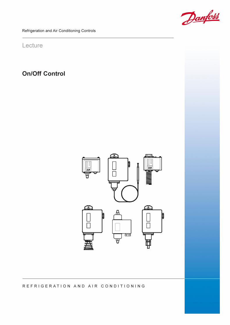
On/Off Control Lecture Refrigeration and Air Conditioning Controls REFRIGERATION AND AIR CONDITIONING
Transcript of On Off Control - FEUP - Faculdade de Engenharia da ...
������������
�������
��������������� ����������������
� � � � � � � � � � � � � � � � � � � � � � � � � � � � � � �

Danfoss A/S (RC-CM/sw), 02 - 2002 RF.5X.A1.02 3
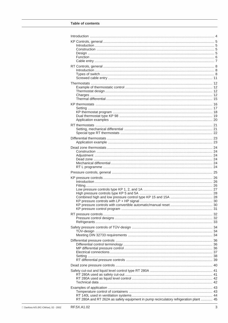
Table of contents
Introduction .................................................................................................................................. 4
KP Controls, general .................................................................................................................... 5Introduction ............................................................................................................................. 5Construction ........................................................................................................................... 5Design .................................................................................................................................... 5Function .................................................................................................................................. 6Cable entry ............................................................................................................................. 7
RT Controls, general .................................................................................................................... 8Introduction ............................................................................................................................. 8Types of switch ....................................................................................................................... 8Screwed cable entry ............................................................................................................. 11
Thermostats ............................................................................................................................... 12Example of thermostatic control ........................................................................................... 12Thermostat design ................................................................................................................ 12Charges ................................................................................................................................ 12Thermal differential ............................................................................................................... 15
KP thermostats .......................................................................................................................... 16Setting .................................................................................................................................. 17KP thermostat program ........................................................................................................ 18Dual thermostat type KP 98 ................................................................................................. 19Application examples ........................................................................................................... 20
RT thermostats .......................................................................................................................... 21Setting, mechanical differential ............................................................................................ 21Special type RT thermostats ................................................................................................ 22
Differential thermostats .............................................................................................................. 23Application example ............................................................................................................. 23
Dead zone thermostats .............................................................................................................. 24Construction ......................................................................................................................... 24Adjustment ........................................................................................................................... 24Dead zone ............................................................................................................................ 24Mechanical differential .......................................................................................................... 24RT L programme .................................................................................................................. 24
Pressure controls, general ......................................................................................................... 25
KP pressure controls .................................................................................................................. 26Introduction ........................................................................................................................... 26Fitting .................................................................................................................................... 26Low pressure controls type KP 1, 2, and 1A ........................................................................ 27High pressure controls type KP 5 and 5A ............................................................................ 28Combined high and low pressure control type KP 15 and 15A ............................................ 28KP pressure controls with LP + HP signal ............................................................................ 30KP pressure controls with convertible automatic/manual reset ............................................ 30KP pressure control program ............................................................................................... 31
RT pressure controls .................................................................................................................. 32Pressure control designs ...................................................................................................... 32Refrigerants .......................................................................................................................... 33
Safety pressure controls of TÜV-design .................................................................................... 34TÜV-design .......................................................................................................................... 34Meeting DIN 32733 requirements ........................................................................................ 34
Differential pressure controls ..................................................................................................... 36Differential control terminology ............................................................................................. 36MP differential pressure control ............................................................................................ 36Electrical connections ........................................................................................................... 37Setting .................................................................................................................................. 38RT differential pressure controls .......................................................................................... 39
Dead zone pressure controls ..................................................................................................... 40
Safety cut-out and liquid level control type RT 280A ................................................................. 41RT 280A used as safety cut-out ........................................................................................... 41RT 280A used as liquid level control .................................................................................... 42Technical data ...................................................................................................................... 42
Examples of application ............................................................................................................. 43Temperature control of containers ....................................................................................... 43RT 140L used in ventilation systems .................................................................................... 44RT 280A and RT 262A as safety equipment in pump recirculatory refrigeration plant ............ 45

4 RF.5X.A1.02 Danfoss A/S (RC-CM/sw), 02 - 2002
Introduction
When a refrigeration system is constantlyloaded, and the load balances the cold outputof the system, adjustment is unnecessary. Inpractice, however, there will always befluctuating loads on the main components ofthe refrigeration plant and the plant capacitywill often be higher than the normal coldrequirement. Therefore, a need for regulationarises.
Regulation can be carried out manually butthat requires a large personnel and is notparticularly accurate, therefore, automaticcontrol is used today. To prevent injury topersonnel and damage to refrigerationequipment, plants must be equipped withsafety controls. Danfoss regulatingequipment covers these requirements. Thefollowing deals with those refrigerationcontrols which regulate in accordance withthe on/off principle.
ON/OFF Control,general
The purpose of on/off control is to keep agiven physical variable, e.g. the ambienttemperature, within certain limits or to changeit according to a predetermined programme.
A control system serves to measure the valueof the controlled variable, compare it with thedesired value, and adjust the control unit, bywhich a possible deviation is reduced.
Thermostats and pressure controls for on/offcontrol are two-position regulators where themanipulated variable can only lead to twoconditions: cut-in or cut-out.
The temperature sequence for a roomcontrolled by a thermostat is shown in fig. 1.The rise in the ambient temperature will notoccur at the same time as the valve opens,as some time will pass before this happens,i.e. the dead time Tt. The dead time is definedas the time which will pass from when thevalve opens until the bulb begins to registerthe temperature increase.
At the measuring point the increase will followan exponential function. The tangent to thestarting point of the curve intersects thetangent to the final value of the curve atTt + Ts.
Ts is denoted the time constant and indicatesthe time it takes for the temperature toincrease to 63% of the final value.
In other words, the time constant is anexpression of the rate at which the controlledvariable changes as a result of a suddenchange of the manipulated variable.
Because of the great difference intemperature the curve of temperature willincrease most rapidly at the beginning, tofade out gradually and approach the finalvalue tangentially.
When the temperature has increased to thepoint A the thermostat will cut-in and thecooling begins. However, it takes some time -τ1 - before the ambient temperature begins tofall.
T1 depends on the following factors amongothers:• Bulb position• Air circulation at the bulb• Sizing of the refrigeration plant.
During cooling the temperature drops to thepoint B where the thermostats cut out therefrigeration system. Because of the coldaccumulated there will, however, be a certainafter-cooling - τ2 - before the temperatureincreases again. The cooling is restarted atthe point A, and a new cycle begins.
td (= the section A to B) denotes the thermaldifferential of the thermostat, whereas tmax
indicates the maximum temperaturefluctuations.
C: TemperatureD: Time

Danfoss A/S (RC-CM/sw), 02 - 2002 RF.5X.A1.02 5
KP Controls, general
Introduction
KP controls are pressure-controlled switchesfor on/off control of refrigeration, freezing,and air-conditioning plant. The KP is basedon entirely new design principles. Themechanical parts of the control have twobalanced positions only. Therefore, thecontact system operates with well-definedcontact pressure. This means that:
• KP has very high contact load both forinductive and ohmic loads
• KP is not sensitive to vibrations andpulsations
• KP has a long mechanical life• KP is free of radio interference, in
accordance with VDE 0875 and CISPR.
Construction The enclosure is a dust-tight mild steel casingprovided with a cover of self-closing ABS-plastic. The grade of enclosure is IP 44 inaccordance with IEC 144 and DIN 40050.
This grade of enclosure is obtained bymounting the control onto a plane board or abracket. The bracket must be placed on thecontrol so that all free holes are covered.
Design
Fig. 4. KP-thermostat Fig. 5.
1. Adjustment setting spindle 2. Differential spindle 3. Main arm18. Locking plate
Fig. 2. KP-thermostat Fig. 3. KP-presssure control
The one function, terminals 1-4, may forexample, cut-in a refrigeration compressor atincreasing pressure/temperature, while thesecond function, terminals 1-2, may cut-in asignal lamp when the refrigerationcompressor has stopped.
KP controls have simple electricalconnections, as both the contact terminalsand the earthing screw are accessible fromthe front. See fig. 5. Thus, several KPcontrols can be mounted close to each other.
KP has very small overall dimensions(84 ∞ 61 ∞ 45 mm), and is of simple androbust design.
KP is fitted with an SPDT switch. See fig. 4.Such a switch has a wide range ofapplication, among other things because themake and break functions can be obtained atincreasing as well as decreasing pressure/temperature. By connecting the threeterminals 1, 2, and 4, two contact functionsare obtained.

6 RF.5X.A1.02 Danfoss A/S (RC-CM/sw), 02 - 2002
KP Controls, general
FunctionThe design principle of the KP controls.
The main spring (7) can by means of theadjustment spindle (1) be adjusted forbalancing the pressure in the bellows.
KP is designed so that the snap action of thecontact system is led to the bellows (9). Thus,this has two balanced positions only. Thebellows is moved only when the cut-in andthe cut-out value is exceeded.
The knife-edge bearing at the tumbler (16)exert two forces on it – on one side thepressure of the bellows (9) minus the force ofthe main spring (7) – on the other side thepull of the differential spring (8).
From the above description it can be seenthat the KP design distinguishes itselfessentially from the design principlespreviously used for mechanical thermostatsand pressure controls.
Contrary to the previous principles, whichwere called “road proportional” or “distanceproportional”, the power transmissionbetween the bellows and the contact systemof the KP is based on the “power proportionalprinciple”.
The following is a description of how theprinciple is put into operation:
Fig. 6 shows a KP control with the contacts 1-4 open, and 2-1 closed. If the pressure in thebellows increases, neither contacts will moveuntil the bellows pressure has reached avalue equal to or higher than that set on themain spring.
When this pressure has been reached themovable parts of the control movemomentary, so that the contact systemchanges to the opposite contact position,where contacts 1-4 are closed, and contacts2-1 are open.See fig. 7.
Generally, on contact systems, when themovable contact hits the fixed one at highspeed, the movable contact will jump back acouple of times. Each time the contacts jumpapart arcing occurs. Consequently thecontact surfaces wiIl melt, and can weldtogether when meeting again.
These very small welds, which occur duringcut-in, are the most frequent cause of failurein a contact system.
The time from the moment when the movablecontact hits the fixed one for the first time,until the cut-in function is established is called“bounce time”. The bounce time for the KPcontact system is less than 100microseconds = 1/10 000 second, which isexceptional. It is 10-50 times less than forcommon contact systems and permits highcontact load combined with long electricaland mechanical life.
The electrical data for the constant systemare:• Alternating current
16 (16) A 400 V a.c.Locked rotor 112 Ai.e.:- 16: maximum ohmic load in amp.- (16): maximum full load current at
inductive load- 400 V: maximum permitted voltage- Locked rotor 112 A: maximum permitted
starting current.
In practice the high contact load means thatsingle phase alternating current motors ofup to 2 hp can be direct started.
• Direct current12 W 220 V d.c. pilot current
Fig. 6 Fig. 7
1. Adjustment setting spindle 2. Differential spindle 3. Main arm 7. Main spring 8. Differential spring 9. Bellows16. Tumbler18. Locking plate20. Contact system

Danfoss A/S (RC-CM/sw), 02 - 2002 RF.5X.A1.02 7
KP Controls, general
Cable entry
KP controls have a soft rubber entry asstandard. See fig. 9. The entry will takecables from 6 to 14 mm diameter.
As accessories Pg 13,5 and Pg 16 cableentries are available, fig. 8.
Fig. 8 Fig. 9

8 RF.5X.A1.02 Danfoss A/S (RC-CM/sw), 02 - 2002
RT Controls, general
Introduction
Types of switch
Fig. 12
Discription
Type of switch normally used for RT. Terminals 1-4 make on increases.Terminals 1-2 make on decreases.Terminal 1 is common.
Single-pole change-over switch with neutral centre position.Terminals 1-4: Make the circuit when the temperature/pressure increases.Terminals 1-2: Make the circuit when the temperature/pressure decreases.The neutral setpoint will be dealt with in the section of dead zonethermostats, page 22.
Single-pole switch breaking two circuits at the same time when the pressure/temperature increases. Momentary contact change-over. Terminals 1-4 and1-2 are cut-out when the pressure/temperature increases.
Single-pole switch making two circuits at the same time when the pressure/temperature increases. Momentary contact change-over. Terminals 1-4 and1-2 are cut-in when the pressure/temperature increases.
Single-pole change-over switch with non-snap action. It gives lessmechanical differential than 17-4030, but the rated capacity is, therefore,lower and the switch must not be used where vibration occurs.
Single-pole switch with the same functions as described for switchNo. 17-4030.The switch is equipped with silver contacts coated with gold.Therefore, it can be used with advantage for small electrical loads as well asin plants where the demand is for exeptional make reability, even after longperiods of intermittent contact load.
Code Nos Fig.
17-4030 13-14
17-4032 15
17-4036 16
17-4034 17
17-0181 18
17-4240 19
Fig 13
Fig 15
Fig 17
Fig 19
Fig 14
Fig 16
Fig 18
Designs and materialsMost RT controls are equipped with switch17-4030 which is an SPDT system (SinglePole Double Throw system). Switch 17-4030can be replaced, without adjusting thecontroller. The switch has a transparentprotective cover over the moving parts.
Replacement systems are also equipped witha protective cover over the contact arm. Thissystem is also available with manual reset onactuation for rising or falling pressure/temperature (max. reset and min. resetrespectively).
Danfoss’ RT controls are characterized by ahoseproof bakelite housing which is equippedwith a steel cover, robust construction, andsmall differentials. Therefore, the control aresuitable for industrial systems.
The RT-control is a pressure or temperature-controlled electric switch which makes orbreaks an electric circuit depending onpressure or temperature variations at thebulb.
Fig. 10. RT thermostat Fig. 11. RT pressure control

Danfoss A/S (RC-CM/sw), 02 - 2002 RF.5X.A1.02 9
RT Controls, general
Type of switch a.c. d.c.
Non-inductive Inductive rating
Full-load LockedCode No. current rotor
17-403010 A 400 V 4 A 400 V 24 A 400 V 12 W 220 V
17-4032
17-403610 A 400 V 3 A 400 V 18 A 400 V 12 W 220 V
17-4034
17-0181 25 VA 24 V 25 VA 24 V
17-4240 10 A 400 V 2 A 400 V 12 A 400 V 12 W 220 V
Rating
Marking
The covers of switches 17-4030 and 17-4032are marked:10 (4) 400 V a.c.12W 220 V d.c.The marking complies with the demands ofVDE 0671 test class �� which prescribes theabove rating in relation to a minimum of100,000 operations.
Fig. 20
Alternating current (a.c.)It should be remembered that the two maindemands are 10 A non-inductive rating and30 A locked rotor. The 4 A inductive rating(or, more correctly, motor rating) is derivedfrom 30 A locked rotor, since the maximumratio between locked rotor/operating currentfor single-phase motors is approx. 7.530 = 4 A7.5
This means that normally motors with anoperating current of 4 A can be connected. Itis permissible to connect motors with a higheroperating current than 4 A, provided that“locked rotor” does not exceed 30 A.

10 RF.5X.A1.02 Danfoss A/S (RC-CM/sw), 02 - 2002
RT Controls, general
Application of two-circuit switches
An RT control with a switch 17-4034 or17-4036 can, for example, be used in pilotcircuits with several RT controllers. When theabove types of switch are used, auxiliaryrelays can be omitted.
The two examples, fig. 21 and fig. 22, showthe wiring diagrams for thermostatic control oftwo deep-freeze stores and one refrigeratedstore, where the three evaporators areconnected to a centrally located compressor.
The thermostats control the opening andclosing of the solenoid valves in the liquidlines, depending on the ambient temperature.
Fig. 21 shows the wiring diagram for RTthermostats with a standard switch 17-4030and auxiliary contacts. Fig. 22 shows thesame system, but in this case the switcheshave been replaced by the two-circuitswitches 17-4034, and the auxiliary contactscan thus be omitted.
Fig. 22
Fig. 21

Danfoss A/S (RC-CM/sw), 02 - 2002 RF.5X.A1.02 11
RT Controls, general
Screwed cable entry All RT controls are equipped with a Pg 13.5nylon cable entry.
The rubber ring of the cable entry consists ofconcentric rings which can be taken out toaccommodate cable diameters of from 6 to14 mm.
The rubber rings are made of Nitril rubber.This gives a good seal, and it can be usedwith plastic cables.
Fig. 23

12 RF.5X.A1.02 Danfoss A/S (RC-CM/sw), 02 - 2002
Thermostats
Example of thermostaticcontrol
In the refrigeration system, fig. 24, a roomthermostat is used to control the temperaturein the refrigerated space. When thetemperature of the refrigerated store roomexceeds the value required, the thermostatmakes the circuit to the compressor motor,and the refrigeration system starts. When thetemperature required is reached, thethermostat breaks the circuit to thecompressor motor, and the refrigerationsystem stops.
Thermostat design Thermostats are temperature-controlledelectrical switches which can break or makean electrical circuit, depending ontemperature variations at the bulb.
A thermostat, fig. 25, consists of the followingmain elements:
The power element which consists of the bulb(29), the capillary tube (28), and the bellowselement (23). The most important parts of themechanical section are the spindle (15), therange spring (12), the knob (5) for adjustingthe spring pressure, and the differentialadjusting nut for adjusting the mechanicaldifferential. The switch (16) is a single-polechange-over switch with momentary contactchange-over.
The power element contains a charge, thepressure of which changes with thetemperature at the bulb. A fixed pressurecorresponds to a given bulb temperature. Ifthe bulb temperature increases, the pressurein the power element increases. Hence thespindle is moved until the pressure on thelower side of the bellows balances thecounter-pressure of the main spring.
Fig. 24
Fig. 25
Charges Depending on the field of application, thecharge of a thermostat can be:I : Vapour fade-out chargeII : Adsorption chargeIII: Partial charge
Vapour fade-out and adsorption charges willbe described overleaf since these chargesare used in our thermostats for refrigerationpurposes.

Danfoss A/S (RC-CM/sw), 02 - 2002 RF.5X.A1.02 13
Vapour fade-out charge
Saturated vapour +some liquid
Vapour pressure curve
Room thermostatsEvaporator thermostats
Thermostats for low temperatures
Thermostats
I. Vapour fade-out charge
A vapour fade-out charge consists of a verysmall amount of liquid and the saturatedvapours of that liquid. This type of chargeutilizes the interdependence between thetemperature and pressure of saturatedvapour.
The pressure of the charge depends on thetemperature at the free liquid surface. As longas liquid remains, a pressure increasecaused by ingress of heat into the liquid willprogress according to the vapour pressurecurve for the saturated vapour of the liquid.From the moment the last drop hasevaporated, the pressure increase will, on theother hand, follow the curve for superheatedvapour. At this point the pressure increase isconsiderably slower since it is now only thethermal expansion of the vapour whichcauses the pressure to increase.
The temperature at which the vapour passesfrom saturated vapour to superheated vapouris called the pressure limiting temperature,denoted t3 in fig. 26.
The advantages of a vapour fade-out chargeare e.g.1. A very short reaction time (a short time
constant). Heat has only to be supplied orgiven off for the respective evaporationand condensation of a very small quantityof liquid.
2. The charge is pressure-limited, i.e. theelement is designed to resist temperatureshigher than the maximum temperaturesetting.
Fig. 26
Small reaction timePressure limited
No capsule sensivityCapillary sensor
The coldest part of the thermostaticelement controls the function
Pressure-temperature curve: Non-linear
It can be seen from the inclination of thevapour pressure curve (fig. 28) that thedifferentials at the lower and upper parts ofthe curve are different when a given pressurevariation Ðp is kept constant. A thermostatwith a vapour fade-out charge has, therefore,smaller mechanical differentials at the upperend of its temperature range than at the lowerend.
Vapour fade-out charges are preferable forthermostats which are to work at lowtemperatures.
In a vapour-filled thermostat the charge willcondense at the coldest point of the powerelement, and the thermostat will regulate thetemperature accordingly. Therefore, to obtainthe regulation required it is a condition thatthe bulb must always be placed colder thanthe rest of the power element.
Fig. 28
+ –
Fig 27.

14 RF.5X.A1.02 Danfoss A/S (RC-CM/sw), 02 - 2002
Thermostats
II. Adsorption charge Adsorption charge is no doubt the mostinteresting one and the charge which is mostuniversally applicable. By using the same twosubstances, e.g. active carbon as adsorbentand CO2 as adsorbate, it is possible toproduce many different pressure-temperaturecurves by varying the ratio between thequantities of the substances.
Some porous substances, adsorbents, havethe capacity of being able to bind moleculesfrom another substance, the adsorbate, intheir microscopic pores. Because of theporosity of the adsorbent, it has a surfacearea of several hundred m2 per gram.
If, in this way, CO2 molecules are bound toactive carbon in a closed container, thepressure is reduced. In the gaseous phase,CO2 is known to participate in the pressureformation by means of its partial pressure.
The capacity of an adsorbent to bind anadsorbate depends on temperature. Whenbinding occurs in a closed system, it alsodepends on the counter-pressure which is setup.
If the adsorbent is heated, it can no longerretain all the gas molecules previouslyretained by it. Some of them will be released,and, together with the other gas moleculeswhich were already free, they will increasethe concentration of gas molecules. Thepressure in the element then increases.
Fig. 31
Fig. 29
Fig. 29 shows a pressure-temperature curvefor an adsorption charge. The S-shape istypical for these curves. When carboncharges are used in power elements, thetemperature range is mostly placedsymmetrically about the turning point tv.Hence, a maximum pressure increase isobtained by means of aminimum quantity of carbon, and hence thesmallest size of bulb. A great advantage ofthe adsorption charge is that a thermostatwith this charge is CROSS AMBIENT, i.e. thebulb can be placed warmer or colder than thethermostat housing.
This is possible because the carbon is alwaysplaced in the bulb. Therefore, the bulb alwayscontrols the thermostatic regulation.
Adsorption charge
Granulated material +superheated gas
Physical mass attraction
Room thermostatsThermostats for high temperatures
Cross ambientSmall bulb
Pressure-temperature curve: Linear
A disadvantage of an adsorption charge isthe capsule sensitivity. This means thatgreater temperature fluctuations at thecapsule may influence the control accuracy.
Capsule sensitiveModerate reaction time
+ –
Fig. 30

Danfoss A/S (RC-CM/sw), 02 - 2002 RF.5X.A1.02 15
Thermostats
Thermal differential The thermal differential is the differential atwhich the system operates. It is alwayshigher than the mechanical differential. Thethermal differential depends on severalfactors:
1. Velocity of medium.The higher the velocity at which the air orliquid pass the sensor, the smaller thethermal differential. Therefore, the sensorshould always be located at a point withgood circulation of the air and the liquidrespectively.
2. Temperature variation rate of medium(temperature variation per time unit).The thermal differential increases with thetemperature variation rate.If the temperature is to be controlled in therange from –5°C to +30°C, to ensure thatthe thermal differential will not beincreased because of too high atemperature variation rate, an RT 4thermostat with an electric heater in thebellows element can be used.
3. Heat transmission to the sensor.The sensor should have optimum contactwith the medium to be temperature-controlled. Difficulties occur especially ifthe sensor is inserted in a pocket, wherethe thermal conduction between sensorand pocket is poor. The application of aheat-conductive compound betweensensor and pocket will, normally, result insatisfactory heat transmission.
Measuring the time constant
To get an idea of what the time constant canbe, measuring has been done on an RT 14with an adsorption charge. The measuringwas done under the following conditions:
The sensor at 10°C was placed in an aircurrent of 20°C. The contact change-over atincreasing temperature was set at 16.3°C.The time constant τ indicates the time intervalfrom the moment the bulb was placed in theair duct, and until contact change-over tookplace.
Fig. 32
Measuring resultsType RT 14
Air velocity m/s 0.1 0.5 1 1.5
sec. τ 205 147 99 73

16 RF.5X.A1.02 Danfoss A/S (RC-CM/sw), 02 - 2002
KP thermostats
KP thermostats are single-pole double-throw(SPDT) temperature-controlled electricalswitches for on/off control. Typical fields ofapplication for KP thermostats are:- large refrigerated cabinets and display
counters- freezing cabinets and display counters- commercial freezing plant- commercial refrigeration plant- air-conditioning plant
KP thermostats The total temperature range is from -50°C to+180°C with independent temperature anddifferential settings. The thermostats can beobtained with vapour fade-out or adsorptioncharge and with the following sensor, seefig. 33.
As standard range setting KP thermostats areprovided with a knob for range setting.
Fig. 33
1a. Vapour charge1b. Adsorption charge2 Capillary tube sensor3. Capillary tube with a coiled
capillary tube sensor4. 3/8 in. cylindrical or double
contact sensor5. 1/4 in. cylindrical sensor6. ø25 mm duct sensor.

Danfoss A/S (RC-CM/sw), 02 - 2002 RF.5X.A1.02 17
Setting
The setting can be seen in fig. 34. Illustratedhere, the range setting is the maximumactuating value, and the differential is to bededucted from this setting to obtain theminimum actuating value. In addition the cut-in and cut-out functions of the thermostat, isdepending on the terminal connectionapplied. If the thermostat is to start and stopa refrigeration compressor (terminals 1-4) thecut-out temperature is equal to the cut-intemperature minus the differential.
All KP thermostats with vapour fade-outcharge are provided with a setting diagram asshown in fig. 35, to be used for the exactsetting of the thermostat.
Example of settingFor temperature control in a deep-freeze box,the KP 61 thermostat should be set so thatwhen temperature increases, the electriccircuit is made at –17°C (startingtemperature), assuming a requirement for acut-out temperature (stopping temperature) of-24°C. The differential (the value to be set onthe differential scale) must be determined. Inthe diagram for KP 61, fig. 35, the cut-intemperature -17°C is read on the range scale(contact change-over when temperatureincreases). On the horizontal scale (contactchange-over on decreases in temperature)the temperature -24°C is read. The solid linesdifferential curve are followed from theintersection point between the lines from -17°C and -24°C. The differential wanted = 6K can be read from the differential scale.Consequently, the thermostat should be setas follows:Range scale: –17°CDifferential scale: 6 K.
Locking the settingThe range setting spindle (1) or thedifferential setting spindle (2) can be lockedby the locking plate (18). See fig. 36.
KP thermostats
Fig. 35 Fig. 36
Fig. 34

18 RF.5X.A1.02 Danfoss A/S (RC-CM/sw), 02 - 2002
KP thermostat program KP thermostats can be divided into threemain groups:1) KP 61-69, which all - with the exception of
KP 62 - are vapour fade-out charged.(KP 62, is available with adsorption chargeand vapour fade-out charge (roomthermostat)).
2) KP 71-77, which all have an adsorptioncharge (cross ambient)
3) KP 98, which is a dual thermostat.
The table in fig. 37 shows the regulatingranges for group one and two. The typedesignation and the code No. are stamped onthe underside of the control, while theapproval, electrical data, and place of originare printed on the scale plate.
KP thermostats
Fig. 37

Danfoss A/S (RC-CM/sw), 02 - 2002 RF.5X.A1.02 19
KP thermostats
Dual thermostattype KP 98
The thermostat has two separate functions:1. As a protection against too high a
discharge gas temperature. After cut-outthe control must be reset manually (max.reset). This function applies to KP 98,code No. 60L1131 and 60L1132.
2a. As a protection against too high an oiltemperature in the compressorcrankcase. After cut-out the control mustbe reset manually (max. reset). Thisfunction applies to KP 98, code No.60L1131.
2b. As a protection against too low an oiltemperature. At too low an oiltemperature a heating element in thecrankcase is cut-in. When the required oiltemperature has been attained, theheating element is cut-out and thecompressor is ready for start. Thisfunction applies to KP 98, code No.60L1132.
The regulating ranges for the control aregiven in the diagram below:
Type Range [°C] Differential [K] Charge Reset Code No.
Oil: +60 to +120 Oil: fixed 14 max.60L1131
HT: +100 to +180 HT: fixed 25 max.KP 98 Adsorption
OIL: 0 to +30 Oil: fixed 12 aut.60L1132
HT: +100 to +180 HT: fixed 25 max.
Fig. 39
Fig. 38
KP 98 is used partly to safeguard against toohigh a discharge gas temperature onrefrigerant compressors, partly to ensureregulation of the oil temperature in thecompressor crankcase.

20 RF.5X.A1.02 Danfoss A/S (RC-CM/sw), 02 - 2002
Application examples In the following a few examples ofapplications for KP thermostats are given. Inan air-conditioning system, fig. 40, it isdesired to protect the pre-heating coil againstbursting due to frost (low outdoortemperature). For this purpose the frost-protection thermostat KP 61 is used. Thisvapour fade-out charged thermostatdistinguishes itself by the fact that the entirecapillary tube is used as a sensor. Thecapillary tube should be formed over thewhole cross section of the duct. If theinjection air is too cold, KP 61 gives a signalto the actuating motor, which closes thedamper, so that only return air is used.
Temperature control of refrigerated displaycounters etc.In many commercial freezing and refrigeratedcounters there is a need for an attractivelydesigned thermostat with a fixed differentialfor temperature control. Often the controlmust be mounted visibly as an integrated partof the counter without spoiling the totalimpression. See fig. 41.
Danfoss’ thermostat programme includes aKP 61 with a top plate, fig. 42, speciallydesigned for surface mounting.
The advantages with this thermostat are:- it can be operated from one side- hand switch STOP/AUTO- simple surface mounting.
Fig. 42
KP thermostats
Fig. 40
Fig. 41

Danfoss A/S (RC-CM/sw), 02 - 2002 RF.5X.A1.02 21
RT thermostats
An RT thermostat is a temperature-controlledelectric switch which makes or breaks anelectrical circuit depending on temperaturevariations at the bulb.Our RT thermostats are characterized by ahoseproof bakelite housing which is equippedwith a steel cover, robust construction, andsmall differentials. Therefore, the controls aresuitable for industrial systems.
Fig. 43 shows the design of an RTthermostat. As mentioned above, the powerelement contains a charge, the pressure ofwhich varies with the temperature at the bulb.The main spring can be set for differentpressures within the setting range. Thepressure in the bellows element counteractsthis pressure. A pressure change in thebellows moves the main spindle until balanceis re-established between the forces. Themovement of the main spindle is transferredto the contact arm of the switch by a guidingknob and a differential adjusting nut so that abreak or make function can be obtained.
Setting,mechanical differential
Fig. 43
By turning the knob, the lowest temperatureat which the switch is to operate is set on therange scale (break or make the circuit).
The mechanical differential is then set byturning the differential adjusting nut.Maximum actuating temperature at the bulb isequal to the actuating temperature + presetmechanical differential. The mechanicaldifferential is set by turning the differentialadjusting nut according to the nomogram fig.45.
Example: Setting of RT 3Range setting = 5°CDifferential required = 2 K
On the nomogram, a setting of the differentialadjusting nut at 4 can be read. Resulting in:- Minimum actuating temperature = 5°C- Maximum actuating temperature
= 5 + 2 = 7°C
Fig. 44
Fig. 45
5. Knob9. Scale19. Differential adjusting nut25. Mounting hole26. Bulb holder30. Bulb pocket31. Capillary tube gland38. Earth terminal
A: Range settingB: Obtained differentialC: Differential setting

22 RF.5X.A1.02 Danfoss A/S (RC-CM/sw), 02 - 2002
RT thermostats
Special typeRT thermostats
Besides covering a large temperature range,there are some types of RT thermostatswhich are suitable for conditions wherespecial demands are made. Of thesethermostats the below types can bementioned:
RT 4 with an electric heater in the bellowselementAs mentioned on page 13 an increased rateof temperature change will increase thethermal differential. To control the ambienttemperature, a small thermal differential is,however, often necessary even if the rate ofair temperature change is high. Theapplication of RT 4 with an electric heater inthe bellows element is recommended for thiskind of system.
The electric heater is heating when therefrigeration compressor is not operating,with the effect that the bellows and thebellows housing are always a little warmerthan the phial.Without this arrangement, the bellows andthe bellows housing would become thecoldest parts of the power element at rapidlyincreasing temperatures, since the mass ofthe bellows housing is larger than that of thephial, and the charge vapours wouldcondense in the bellows and thus not createthe requisite pressure for changing over theswitch.
RT thermostats with small differentialsDanfoss has developed thermostats withsmall differentials. These types are: RT 21,23 and 24 as well as RT 17 and 103. Thetechnical data can be seen in the below table.The thermostats cover a range from –50°C to+45°C.
Nature of controls Type Charge Range [°C] Mechanical differential [K]
5 to 18RT 2 –25 to 15 6 to 20
Brine, surface or 1 to 3RT 23 Adsorption 5 to 22room thermostat 1 to 3
1.4 to 4RT 24 15 to 34 1.4 to 3.5
2.2 to 7RT 17 –50 to –15 1.5 to 5VapourRoom thermostat fade-out 10 to 45 1.3 to 7RT 103 1 to 5
Fig. 46

Danfoss A/S (RC-CM/sw), 02 - 2002 RF.5X.A1.02 23
Differential thermostats
An RT differential thermostat is a single-poleelectric change-over switch, the contactposition of which is controlled by thetemperature difference between the twobulbs of the thermostat.
RT 270 is designed for use in processingplants, ventilation plants, refrigeration andheating plants where it is desired to maintaina fixed temperature difference of from 0°C to15°C between two media.
One sensor temperature is used as areference and the other as an indirectlycontrolled variable. (The directly controlledvariable is the temperature differential).Fig. 47 shows a cross section of an RT 270.
The differential thermostat is equipped withtwo bellows elements: the LT element, thesensor (1) of which is to be placed in themedium with the lowest temperature, and theHT element, the sensor (2) of which is to beplaced in the medium with the highesttemperature.
The range spring (3) has a rectilinearcharacteristic. Within the differential range itcan be set for different temperaturedifferentials by rotating the setting disc (4).The setting indicates the scale value at whichcontact change-over occurs when the spindlemoves downwards. (Contacts 2-1 make thecircuit).
When the differential between the LT and HTbulb temperatures is reduced, the spindle (5)moves downwards and thus actuates thecontact arm (7) of the switch via the upperguiding knob (6).
When the temperature differential betweenHT and LT increases, the switch changesover when the temperature differential hasincreased to the setting plus the fixed contactdifferential of approx. 2 K.
Application example It is desired to maintain a temperature at 5°Cabove another temperature which is assumedto be constant at 12°C. The LT sensor isplaced in the medium with the lowesttemperature (reference temperature) and theHT sensor in the medium with the highesttemperature (controlled temperature). Thethermostat is set for a temperature differentialof 5 K.
It is assumed that at first the controlledtemperature is 14°C. The main spindle thenmoves downwards and closes the contacts1-2 because the actual differential of14 - 2 = 2 K is smaller than the desireddifferential of 5 K.
When the contacts 1-2 are closed, a heatingsystem is cut-in so that the controlledtemperature increases, and the main spindlemoves upwards until the differential betweenthe sensor temperatures is 7 K = settingdifferential plus contact differential.Afterwards the controlled temperature willthen fluctuate between 19°C and 17°C.
If the reference temperature (LT temperature)falls or in creases, the HT temperature fallsand increases proportionately. Thedifferential will continue to fluctuate between7 K and 5 K.
Fig. 48
Fig. 47

24 RF.5X.A1.02 Danfoss A/S (RC-CM/sw), 02 - 2002
Nature of controls Type Charge Range [°C] at low temp. °C at low temp. °C
RT 8L –20 to +12 1.5-4.4 1.5-4.9Brine surface orroom thermostat RT 14L Adsorption –5 to + 30 1.5-5 1.5-5
Air duct thermostat RT 140L + 15 to +45 3-4.5 2-5
VapourRoom thermostat RT 16L 0 to +38 1.5-5 0.7-1.9fade-out
Dead zone thermostats
The RT L thermostats have an adjustabledead zone since they are fitted with a threeposition contact system, code No. 17-4032.
Construction Fundamentally the RT L thermostats areconstructed as the other RT controls but tosatisfy the dead zone function the contactsystem has two contact levers which meshwith two guide rollers, see fig. 49.
Adjustment,fig. 41 and 50 The adjusted scale value corresponds to the
break value of contact 2-3. The required deadzone is found in the diagram for the particularcontrol.
On the lower scale of the diagram theposition in which the setting knob should beset, is read off.
Dead zone The interval of the controlled variable duringwhich the control device is at rest is calledthe dead zone. Looking at fig. 50 the deadzone is the interval where no make function isobtained.
Mechanical differential The interval between the values of thecontrolled variable making the control devicemove is called mechanical differential.
RT L programme RT L controls are available in various designsas shown in the table.
Fig. 49
Fig. 50

Danfoss A/S (RC-CM/sw), 02 - 2002 RF.5X.A1.02 25
Pressure controls, general
A pressure control contains a pressureoperated change-over switch the contactposition of which depends on the pressure inthe bellows. Via the pipe connector thebellows is connected to the pressure in theplant. The fundamental layout is shown in fig.51.
The main spring (12) can be set for differentpressures to balance the pressure on thebellows. On a rise in pressure the bellows isaffected so that the main spindle (15) movesupwards until the spring and bellowspressures are in equilibrium. The movementson the main spindle are then transferred tothe electric contact system.
12. Main spring15. Main spindle16. Contact system (RT)23. Bellows element27. Pipe connector44. Range spindleFig. 51

26 RF.5X.A1.02 Danfoss A/S (RC-CM/sw), 02 - 2002
KP pressure controls
Like the KP thermostats the KP pressurecontrols are single pole electrical switches.
As standard, pressure controls for freon aresupplied with 1/4 in flare, 6mm or 1/4 insolder connection, or with 1 m fixed capillarytube with 1/4 in flare connection. Dependingon the type, the connection must be made onthe suction and/or pressure side of therefrigeration plant.
The controls for ammonia are provided with a1 m loose capillary tube of steel. Generally,KP pressure controls can be used for allfluorinated refrigerants, but those forammonia are made from materials which willtolerate this refrigerant.
KP pressure controls are made in thefollowing basic types:- low pressure controls- high pressure controls- combined high and low pressure controls
Fitting The pressure control can be fitted using oneof the two types of brackets shown in fig. 53.These may be ordered separately. When wallmounting, the plain holes in the back of thecontrol are to be used.
The KP pressure controls can be fitted in anyposition. However, as shown in fig. 52, thecapillary tube is fitted in a way preventingdirect downpiping of oil and refrigerant. In thisway the risk of blocking the bellows iseliminated, and at the same time a correctpressure control is ensured.
Fig. 52
Fig. 53
Introduction

Danfoss A/S (RC-CM/sw), 02 - 2002 RF.5X.A1.02 27
KP pressure controls
Low pressure controlstype KP 1, 2, and 1A
As previously mentioned the KP 1 and 2 areprovided with 1/4 in flare connection, fig. 54,or with 1 m fixed capillary tube, fig. 55.
KP 1A is provided with a 1 m loose capillarytube of steel, fig. 56. The low pressure controlsmust be connected to the suction side.
The function of the control may be, forexample:1) Used to start and stop the compressor,
depending of the pressure in the suctionline. At too low a pressure the compressoris cut-out. When the pressure hasincreased by a value corresponding to thedifferential, the circuit to the compressormotor is made again.
2) Used as a low pressure safety switch. Thepressure control will cut-out thecompressor at too low a suction pressure.The compressor can then for example becontrolled by a room thermostat.
Fig. 54
The range spindle (1), and the differentialsetting spindle (2) can be locked by thelocking plate (18), fig. 57.
The normal function of the low pressurecontrol - cutting out the compressor atdecreasing suction pressures - is shown infig. 58. The electric connection to theterminals of the contact system are alsoshown as well. The cut-in value (terminals 1-4) required is set on the range scale (START)of the control. See fig. 59. The differentialrequired is set on the differential scale,(DIFF). The cut-out value (STOP) (terminals1-2) is then derived from the expression:
STOP = START minus DIFF
KP 1 and 1A are also available in a designwith minimum reset. See fig. 60. A manualreset can be carried out only when thepressure has increased by a value higherthan or equal to the fixed differential. Thescales on KP 1 and 1A reset controls arecalibrated differently from the remaining KPlow pressure controls.
On these reset controls the scale valuecorresponding to the required cut-out value(STOP), while the scale value for theremaining KP low pressure controlscorresponds to the cut-in value (START). KPlow pressure controls with minimum resethave a locking plate on the range spindle, sothat both the cut-in and the cut-out values ofthe control are fixed.
Fig. 55 Fig. 56
Fig. 57
Fig. 58
Fig. 59
Fig. 60

28 RF.5X.A1.02 Danfoss A/S (RC-CM/sw), 02 - 2002
KP pressure controls
High pressure controlstype KP 5 and 5A
KP 5 and 5A are usually connected to thehigh pressure side of the refrigerationcompressor. The usual function of the highpressure control is to cut the current supply tothe compressor motor or relay, when thepressure exceeds that set on the range scale.
KP 5 and 5A can be obtained in two designs:1) With adjustable differential, fig. 61.
In this design the compressor isautomatically cut-in again, when thepressure has fallen by a value equal to orhigher than the differential setting. Theelectric connection of the high pressurecontrol can be seen in fig. 62, and alsohow it is set. The cut-out value (terminals1-4) required is set on the range scale(STOP) of the control. See fig. 63. Thedifferential required is set on thedifferential scale (DIFF), fig. 61. The cut-invalue (START, terminals 1-2) is thenderived from the expression
START = STOP minus DIFF
The locking plate can lock both spindles.Fig. 62Fig. 61
2) With maximum reset-function and fixeddifferential setting (4 bar), fig. 63.This type of pressure control is used as asafety switch and can be manually resetonly when the pressure has fallen by avalue equal to or higher than the fixeddifferential of 4 bar. The pressure control isprovided with a locking plate, whichensures that the range setting is locked.For safety reasons it is often desirable toseal reset controls. This can be done byusing a DIN-standardized sealing screw,see fig. 64. The sealing screw must beordered separately.
Fig. 64
Combined high and lowpressure control type KP15 and 15A
Fig. 63
Fig. 65
1. low pressure setting spindle, LP2. differential setting spindle, LP3. main arm5. high pressure setting spindle, HP
18. locking plate

Danfoss A/S (RC-CM/sw), 02 - 2002 RF.5X.A1.02 29
With maximum resetIt has been possible to work out, practically,the reset function for all KP controls withreset, so that a control will start operatingtogether with the change-over. The setting ofKP 15 and 15A with maximum reset followsthe same procedure as described in thesection concerning controls without reset.When the compressor is cut-out because oftoo high a condensing pressure, the resettingof controls with maximum reset cannot takeplace until the pressure has fallen to approx.4 bar below the cut-out pressure setting onthe high pressure scale. Reset can beperformed only by actuating the maximumreset knob manually. See fig. 67.
KP pressure controls
KP 15 and 15A are combined low and highpressure controls having setting facilities bothon low and high pressure sides. As shown infig. 65, the functions of the low pressure sideand the high pressure side are mechanicallyseparated. This means that both the lowpressure side and the high pressure side areable to cut-in and cut-out the compressor,independently.
For safety reasons, the high pressure side isprovided with an internal scale, while the lowpressure side is provided with an externalscale. KP 15 and 15A exist in the followingdesigns:1) without reset, fig. 662) with maximum reset, fig. 673) with minimum/maximum reset, fig. 68
Fig. 68
High pressure settingThe condensing pressure (~ STOP pressure)is determined according to the requiredworking conditioning of the plant. Thispressure is set by means of the high pressurespindle on the internal HP scale of the control.The cut-in value (START pressure) is thenderived from the expression:START = STOP minus DIFF
where DIFF is the fixed differential of approx.4 bar.
Low pressure settingPressure controls with automatic reset – LP:Set the LP start pressure on the “CUT-IN”scale (range scale).One rotation of the low pressure spindle³ 0.7 bar.Set the LP differential so the “DIFF” scale.One rotation of the differential spindle³ 0.15 bar.The LP stop pressure is the LP start pressureminus the differential.Note! The LP stop pressure must lie aboveabsolute vacuum (p = –1 bar)!If with low stop pressure the refrigerationcompressor will not stop, check to ensure thatthe differential value has not been set toohigh!
Pressure controls with automatic reset – HP:Set the HP pressure on the “CUT-OUT” scale.One rotation of the HP spindle ³ 2.3 bar.Set the HP differential on the “DIFF” scale.One rotation of the differential spindle³ 0.28 bar. The HP start pressure is the HPstop pressure minus the differential.
Pressure controls with manual resetSet the stop pressure on “CUT-OUT” scale(range scale).Low pressure controls can be manually resetwhen the pressure is equal to the stoppressure plus the differential.High pressure controls can be manually resetwhen the pressure is equal to the stoppressure plus the differential.
Start and stop pressures for both the LP andHP sides of the system should always bechecked with an accurate pressure gauge.
Combined high and lowpressure control type KP15 and 15A(cont.)
Fig. 66
Fig. 67
Without resetWhen the compressor is running, terminals A-C are connected. See fig. 65. If the pressureon the HP side exceeds the cut out pressureon the high pressure spindle, or if the suctionpressure on the LP side falls below the cut-out pressure setting, in contact change-overoccurs, so cutting the current to thecompressor motor is cut-out. The compressormotor will restart when the conditions havereturned to normal, i.e:1) either when the suction pressure has
increased by a value equal to or higherthan the differential setting
2) or when the pressure on the condenserside has fallen by a value equal to orhigher than the fixed differential of thecontrol, approx. 4 bar.
As mentioned previously on combined highand low pressure controls the two pressureranges are set separately.

30 RF.5X.A1.02 Danfoss A/S (RC-CM/sw), 02 - 2002
KP pressure controls
With minimum/maximum resetOn KP 15 and 15A with minimum reset thelow pressure scale is calibrated in a waycorresponding to KP 1 and 1A with minimumreset. The STOP value set on the lowpressure scale corresponds to change-overat falling pressures. The cut-out valuerequired on the low pressure side should beset by means of the low pressure spindle.
Cutting-in the compressor motor, which hasbeen stopped because of too low a suctionpressure, cannot take place until theminimum reset knob is actuated, see fig. 68,and not until the pressure has increased by avalue corresponding to the fixed differential of0.7 bar. Setting and restarting after stop onthe high pressure side are described in thesection concerning KP 15 and 15A withmaximum reset.
KP pressure controls withLP + HP signal
On variants of KP 15, KP 15A and 17W withboth LP and HP signal contacts it is possibleto take out two separate signals. The signaltaken will depend on whether the pressurecontrol is to cut out the compressor becauseof too low a suction pressure or too high adischarge pressure.
On HP signal contact mk. D the currentmarking is 50 VA 380 V a.c. / 12 W 220 V d.c.ON LP signal contact mk. B the currentmarking is 16 A 380 V a.c. / 12 W 220 V d.c.(see fig. 71).
Fig. 70 Fig. 71
KP pressure controls withconvertible automatic/manual reset
KP 15 pressure controls with manual resetare available with convertible automatic/manual reset. Convertible automatic/manualreset means that when the unit is installed itis possible to choose between manual resetmode or automatic reset mode on both highpressure and low pressure sides. This facilityis also advantageous when servicing: theinstaller can allow the pressure control tooperate with automatic reset while servicingthe system.
Changeover from one reset function to theother can be performed by turning theeccentric (A) with a screwdriver in the slotprovided (fig. 72).
This function increases flexibility in bothstocking and application, in that the pressurecontrol can be set for four different resetfunctions and thus four different types ofapplication, see table below.
Fig. 72
Low Manual reset Automatic reset Automatic reset Manual resetPressure
High Manual reset Manual reset Automatic reset Automatic resetPressure
et. al.

Danfoss A/S (RC-CM/sw), 02 - 2002 RF.5X.A1.02 31
In fig. 73 is a table of the KP controlprogramme with technical data.
KP pressure controls
KP pressure controlprogram
Fig. 73

32 RF.5X.A1.02 Danfoss A/S (RC-CM/sw), 02 - 2002
RT pressure controls
Pressure control designs The pressure controls are available in threedesigns:1. Low pressure controls which makes the
circuit when the pressure on the suctionside of the system exceeds a preset value,and breaks it when the pressure falls to avalue below the differential setting.
The following types are low-pressurecontrols: RT 1, 1A, 110, 112, 113, 116,121 and 200.
2. High pressure controls which breaks thecircuit when the pressure on the high-pressure side of the system exceeds apreset value, and makes the circuit whenthe pressure falls to a value below thedifferential setting.
The following types are high-pressurecontrols: RT 5, 5A, 6W, 6B, 6S, 6AW,6AB, 6AS, 117 and 118.
The high pressure controls are, normally,supplied without a knob. Instead the mainspindle is covered by a protective cap.Setting is only possible when theprotective cap has been removed.
SettingBy turning the knob, the minimum pressure atwhich the switch is to operate (break or makethe circuit) is set. This value can be read onthe main scale of the control.
Next, the differential is set by rotating thedifferential adjusting nut. Maximum actuatingpressure = minimum actuating pressure +differential setting.
The diagram, fig. 74, shows the number onthe differential scale which corresponds tothe differential required. The diagram appliesto switch 17-4030.
Fig. 74
Fig. 75 Fig. 76
Example:Setting type RT 1 at “7” will result in adifferential of approx. 1.2 bar, while the samesetting on type RT 5A will result in adifferential of approx. 3.0 bar.

Danfoss A/S (RC-CM/sw), 02 - 2002 RF.5X.A1.02 33
RT pressure controls
3. Pressure controls with resetIn those cases where the pressure control isused as a safety cut-out, reset must not beautomatic. Therefore, RT 1 and 1A as well asRT 5 and 5A are available with a reset but sothat reset can only be effected manually afterthe pressure has become normal.
The low pressure controls RT 1 and 1A areavailable in designs with minimum reset (fig.77) which cut-out when the pressure hasfallen to a preset value. Manual reset (41)cannot take place until the pressure in thebellows system has increased to a valuecorresponding to the setting + differential.The factory locked differential adjusting nut(19) has been shortened at the top so that itcannot actuate the arm of the switch whenthe pressure increases. When the pressurefalls, the guiding knob (17) actuates the armof the switch in the usual way, and causes acontact change-over from 1-4 to 1-2.
The scale is calibrated in such a way that thevalue set on the scale corresponds to contactchange-over on decreases in the pressure.
Fig. 77
Fig. 78
The high pressure controls RT 5 and 5A areavailable in designs with maximum reset (fig.78) which cut-out when the pressure hasincreased to a value corresponding to thepressure setting. Manual reset (41) cannot beeffected until the pressure has fallen to avalue which corresponds to the pressuresetting minus the differential. The factorylocked differential adjusting nut (19) is in thiscase used as a guiding knob.
When the pressure increases, the differentialadjusting nut (19) actuates the arm.of theswitch and causes a contact change-overfrom 1-2 to 1-4.
The scale is calibrated in such a way that thevalue set on the scale corresponds to contactchange-over on increases in the pressure,which is quite the opposite of the usual RTcontrols.
Refrigerants All the pressure controls can be used for allfluorinated refrigerants. The RT 1A and 5Adesigns can also be used for ammonia (NH3).

34 RF.5X.A1.02 Danfoss A/S (RC-CM/sw), 02 - 2002
Safety pressure controls of TÜV-design
Today, in West Germany, the TÜV(Technische Überwachungs Verein) exercisesauthority over refrigeration plants. The TÜVdeals especially with safety and, therefore,lays down the following regulations (whichcame into force 1’st December 1974).
A. Accident prevention measures onrefrigeration plants (VBG 20).
B. Instructions and procedures for accidentprevention on refrigeration plants (VBG 20).
TÜV-design Refrigeration plant in operation in Germanyaffected by TÜV’s regulations must beconverted and equipped with safety controlscomplying with DIN 32733 requirements. Thismeans that manufacturers exporting toGermany will have to supply refrigerationplants able to obtain TÜV approval.
Of special interest to Danfoss are TÜVrequirements on high pressure controls withfail-safe bellows elements.
Meeting DIN 32733requirements
TÜV safety pressure controls with fail-safefunctions are covered by three types ofcontrol.- DWK - Druckwächter (pressure control)- DBK - Druckbegrenzer (pressure limiter)- SDBK - Sicherheitsdruckbegrenzer (safetypressure limiter)
These pressure controls must be able to cut-out the refrigeration compressor, when thecut-out pressure is exceeded.A parallel requirement is, that the pressurecontrol must cut-out the refrigerationcompressor if the bellows ruptures.
A practical solution of this problem has beenfound by providing the pressure controls witha bellows element consisting of an externaland an internal bellows. The space betweenthe bellows is evacuated, so that thepressure control will cut-out the compressor,if one of the bellows ruptures.
The cross-sectional drawings show someTÜV approved controls.Please, note the bellows elements with thetwo bellows.
Fig. 79 Fig. 81
Fig. 80 Fig. 82

Danfoss A/S (RC-CM/sw), 02 - 2002 RF.5X.A1.02 35
Regulation Mechanicalrange differential
Pressure DINType 2) Reset
Connection approvals∆Pbar
RT 36 B0∅ 2.5 fixed 0.2 1/4 in. / 6 mm flare manual DBK 4B04091
RT 36S
RT 30AW fixed 0.7 automatic DWK 4B03991
RT 30AB 1∅ 10 1/2 BSP ext.fixed 0.5 manual DWK 4B03891
RT 30 AS
RT 6W 5∅ 25 fixed 3 automatic DWK 4B03791
RT 6B 1/4 in. / 6 mm flare10∅ 28 fixed 1.5 manual DBK 4B03691
RT 6S
RT 6AW 5∅ 25 fixed 3 automatic DWK 4B03791
RT 6AB10∅ 28 fixed 1.5 manual DBK 4B03691
RT 6AS
1) Meets the requirements in VBG 20 dealing with safety equipment and excess pressures.2) W = Wächter (pressure control, B= Begrenzer (pressure control with ext. reset), S = Sicherheitsdruckbegrenzer (pressure control with int. reset):
A bellows rupture will cause the refrigeration plant compressor to stop.
3/8 BSP ext. +∠ 6.5 / ∠ 10 mm
weld nipple
Safety pressure controls of TÜV-design
KP pressure controls with DIN 32733 approval 1)
Low pressure (LP) High pressure (HP) Reset
Regulating Differential Regula- Differential Highrange ting press. Contact DINPressure Type 2)
system approvalsrange∆p ∆p
bar bar bar bar HP
High KP7W 8∅ 28 4∅ 10 aut. SPDT DWK 4B00194
High KP7B 8∅ 28 fixed 4 man. SPDT DBK 4B00394
High KP7S 8∅ 28 fixed 4 man. SPDT DBK 4B00394
KP7BS 8∅ 28 fixed 4 man. SPST DBK/DBK 4B00294
KP7ABS 3) 8∅ 28 fixed 4 man. SPST DBK/DBK 4B00294
SPDT +Dual KP17W 0.2∅ 7.5 0.7∅ 4 8∅ 28 fixed 4 aut. HP and HD DWK 4B00594
signal
KP17W 0.2∅ 7.5 0.7∅ 4 8∅ 28 fixed 4 aut. SPDT DWK 4B00594
KP17B 0.2∅ 7.5 0.7∅ 4 8∅ 28 fixed 4 man. SPDT DBK 4B00494
1) Meets the requirements in VBG 20 dealing with safety equipment and excess pressures.2) W = Wächter (pressure control, B= Begrenzer (pressure control with ext. reset), S = Sicherheitsdruckbegrenzer (pressure control with int. reset):
A bellows rupture will cause the refrigeration plant compressor to stop. A rupture of the outer bellows wiill cause the stop pressure to fall approx. 3 bar under the set value.3) KP 7 ABS can also be used for R 717 (NH3).
RT pressure controls with DIN 32733 approval 1)
The three designs covering DIN 32733requirement are as follows:
DWK - pressure controlThis type of pressure control is used forregulation. The pressure control resets itself,after having cut-out when the pressure hasfallen by a value equal to the differential.
DBK - pressure limiterThe pressure limiter is for use as a safetyswitch. It operates if the pressure increasesto a value higher than the normal workingpressure.
DBK pressure controls are provided withexternal reset and, therefore, they can bereset only when the pressure has fallen by avalue equal to the fixed differential.
SDB - safety pressure limiterThe safety pressure limiter is also for use asa safety switch, just like the DBK types.
The SDBK pressure limiters have internalreset, meaning that the control cannot bereset until the cover has been removed.
TÜV approved pressure controlsDanfoss market the program of pressurecontrols shown in the table. All the controlsare TÜV approved.
The controls are suitable for the followingcategories of refrigeration plants:- Refrigeration plants with fluorinated
refrigerants- Refrigeration plants with ammonia- Refrigeration plants with turbo refrigeration
compressors.

36 RF.5X.A1.02 Danfoss A/S (RC-CM/sw), 02 - 2002
Differential pressure controls
A differential pressure control is a pressurecontrolled electrical switch which makes andbreaks the circuit depending on the differencebetween the pressures in the two oppositeacting bellows elements.
Within the operating range, the functioning ofthe pressure control only depends on the saidpressure difference, where as it is independentof the absolute pressures which act on thebellows. The differential pressure control isused for protecting refrigeration compressorswith forced lubrication, where under anyoperating conditions the oil pressure has to bekept higher than the suction pressure or thecrankcase pressure. Furthermore, thedifferential pressure control can be used for theprotection of filters, pumps, etc.Fig. 83
Differential controlterminology
Differential rangeThe difference in pressure between the “OIL”and the “LP” connections within which thedifferential pressure control can be set tooperate.
Scale readingThe difference that exists between the “OIL”and “LP” pressures at the moment thecontact system changes over when the mainspindle travels down. The downward travelcorresponds to falling differential pressure.
Function rangeThe pressure range on the “LP” connectionwithin which the differential pressure controlis able to operate.
3. LP connection4. LP bellows element5. Setting disc12. Main spring15. Main spindle17. Upper guiding Knob18. Contact system20. Lower guiding Knob24. HP bellows element34. HP connection
Contact differentialThe pressure rise in excess of the setpressure differential which is necessary tomake the contact system change from cut into cut out. See the example in the section“Setting” on page 36.
Release timeThe time the differential pressure controlallows the compressor to run with too low anoil pressure. See the example in the section“Setting” on page 36.
MP differential pressurecontrol
Types MP 54, 55 and 55A are for use assafety controls on pressure-lubricatedrefrigeration compressors. The units will stopa compressor after a certain time in the eventof an oil pressure failure. The MP 54 and 55are for refrigeration plants with fluorinatedrefrigerants like R 12, R 22, R 500 and R502. The MP 55A is for refrigeration plantswithR 717(NH3) and can also be used withfluorinated refrigerants. Types MP 54, 55 and55A have built-in thermal time relay with afixed release time.
Fig. 84

Danfoss A/S (RC-CM/sw), 02 - 2002 RF.5X.A1.02 37
Differential pressure controls
FittingThe differential pressure control can beinstalled in any position. It can be mounteddirect on a wall or on the compressorinstallation panel by using the fitting holes inthe back of the unit. The unit can also beinstalled on a bracket. See “Accessories”.
Bellows element “OIL” is connected to thelubrication system at the point where therequired minimum oil pressure must bemaintained during operation. This willnormally be at the outlet side of the pump orat the discharge from the crankshaftlubrication system.
Bellows element “LP” is connected to thecompressor crankcase. Connection must notbe made to the suction manifold or a similarposition where the pressure can vary fromthe pressure in the crankcase because offlow resistance.
The connection must be made in such a waythat the line to the pressure control cannot beshut off.On R 717(NH3) refrigeration installations andout of consideration for the oil-ammoniamixture viscosity at ambient temperatureslower than approx. +15°C the inside diameterof the connection tube must be at least 4 mm.The weld connection on the MP 55A isdesigned for 04/06 mm steel tube.
Fig. 85
The wiring diagram printed in the cover of theunit shows how the electrical connections areto be made. See fig. 86. Connection terminalS need not necessarily be connected toobtain correct function. Terminal S is for theconnection of a signal lamp which will light upwhen the time relay cuts out the compressorbecause of an oil pressure failure. Ifindication of normal compressor operation isrequired, a signal lamp can be connected inparallel with the motor relay.
Electrical connections If there is a requirement for a heating elementin the crank case oil sump to be cut in duringcompressor standstill periods, an auxiliarycontact in the motor relay or a KP 98 may beused.
As can be seen in fig. 87, the unit containstwo separate electrical circuits. One of theadvantages of this is that the differentialpressure control does not need to be the lastlink in the electrical circuit of the plant. Thecontrol unit (pressure control, thermostat) canbe anywhere in the control circuit, before orafter the differential pressure control.
Fig. 86 Fig. 87

38 RF.5X.A1.02 Danfoss A/S (RC-CM/sw), 02 - 2002
Differential pressure controls
Setting MP 54 has a fixed setting of 0.7 bar differentialpressure and cannot be re-adjusted.
MP 55 and 55ABy inserting a pressure gauge, as shown infig. 88, the lubricating oil pressure (p1) and thepressure in the crankcase (p2) can be read off.The difference between these pressures is theoil pressure available for the lubricationsystem.
The least allowable oil pressure is set byusing the setting disc (3). Turning it upwardsdecreases pressure and vice versa.
NB.: On starting, the oil pressure must rise atleast 0.2 bar over the set value.
ExampleTypes MP 55 and 55A are set at 3 bar = setvalue + fixed contact differential.
If the oil pressure does not reach 3.2 barwithin the release time, current to the coil ofthe motor starter is cut off and thecompressor stops.
Fig. 88
FunctionIf during start the oil fails to reach the setvalue, or if during operation it falls below theset value, the compressor will stop after therelease time has expired. The reset button (4)can be used to cut in the compressor again.Restarting is possible about 2 minutes aftercut out but should not be attempted beforethe reason for the oil pressure failure hasbeen found and the fault corrected.
After restarting the compressor a checkshould be made to see that the differentialpressure control is operating according torequirements.
This check can be carried out by pressing thetest device (5).
When the device is pressed upwards andheld in that position the compressor muststop after the expiration of the release timegiven on the time relay.
The compressor can then be started asdescribed above.
Fig. 89

Danfoss A/S (RC-CM/sw), 02 - 2002 RF.5X.A1.02 39
Differential pressure controls
RT differential pressurecontrols
RT differential pressure controls can bedelivered in two different designs: RT 260Aand RT 262A.
Fig. 90 shows the principle of a RTdifferential pressure control. The bellows (1)and (2) are connected to the LP connection,which is connected to the lower pressure(suction pressure), and the HP connection,which is connected to the higher pressure (oilpressure), respectively. The range spring (3)can be set for different differential pressures,by rotating the setting disc (4).
If the pressure differential between the higherand the lower pressures is reduced, thespindle (5) moves downwards and thusactuates the contact arm of the switchthrough the upper guiding knob.
On increase in the pressure differentialbetween the HP and LP bellows, the switch isactuated to change over when the pressuredifferential has increased to the setting plusthe fixed contact differential setting.
SettingThe setting disc (4) can be turned with ascrewdriver so that the differential pressurecontrol can be set to make the switchchange-over (break or make) at differentrequired differential pressures. The settingcan be read on the main scale.
Contact position. Terminals 1-4If the differential pressure falls below thesetting, the switch breaks the circuit. Theswitch makes the circuit again when thedifferential pressure has increased to thesetting + the fixed contact differential.
ExampleDifferential pressure setting = 2 bar (RT260A). When the pressure falls below thesetting, the switch breaks the circuit.Differential pressure setting + contactdifferential = 2 + 0.3 = 2.3 bar.At this value the switch makes the circuitagain.
Contact position. Terminals 1-2If the differential pressure falls below thesetting, the switch makes the circuit. Theswitch breaks the circuit again when thedifferential pressure has increased to thesetting + the fixed contact differential.
ExampleDifferential pressure setting = 2 bar(RT 260A). When the pressure falls below thesetting, the switch makes the circuit.Differential pressure setting + contactdifferential = 2 + 0.3 = 2.3 bar.At this value the switch breaks the circuit.
Fig. 90
1. LP bellow element2. HP bellow element3. Main spring4. Setting disc5. Main spindle6. Upper guiding knob7. Contact arm
Fig. 91

40 RF.5X.A1.02 Danfoss A/S (RC-CM/sw), 02 - 2002
Dead zone pressure controls
The pressure controls type RT L are controlswith an adjust able dead zone, because theyare equipped with a change-over switch,code No. 17-4032.
DesignIn principle, the RT L pressure controls arebuilt up like the other RT controls, but in orderto comply with the dead zone function, theswitch has two contact arms which engagetwo guiding knobs, see fig. 92.
Setting, fig. 92 and table below.The set scale value corresponds to the breakvalue of contacts 1-4. The dead zonerequired is found in the diagram for thecontrol in question. On the lower scale of thediagram it is then possible to read theposition to which the knob is to be turned.
Max. neutralNature of controls Type Range Differential zone
RT 1 AL –0.8 ∅ +5 bar fixed 0.2 bar 0.2 ∅ 0.9 barLow pressure controls RT 200 L 0.2 ∅ 6 bar fixed 0.25 bar 0.25 ∅ 0.7 bar
RT 5 AL 4 ∅ 17 bar fixed 0.35 bar 0.35 ∅ 1.4 barHigh pressure control RT 117 L 10 ∅ 30 bar fixed 1.0 bar 1.5 ∅ 3.5 bar
Fig. 92
RT L pressure control rangeRT L controls can be obtained in differentthermostat and pressure control designs asshown in the above table. They are alsoavailable with gold plated contacts.
Dead zoneThe interval of the controlled variable wherethe control unit is idle is called the dead zone.From the table it can be seen that the deadzone is the interval without a make function.
Mechanical differentialThe interval between the values of thecontrolled variable which makes the controlunit move is called the mechanicaldifferential.

Danfoss A/S (RC-CM/sw), 02 - 2002 RF.5X.A1.02 41
Safety cut-out and liquid level control type RT 280A
RT 280A used as safetycut-out
RT 280A is the designation of a safety cut-outwhich has been designed primarily for use asa protection against too high a liquid levele.g. in separators or pump receivers inrefrigeration plants with pump circulation.
The regulation principle is anon/off controlbased on the thermal conduction differencebetween the liquid and vapour phases of arefrigerant.
In principle, the RT 280A is-built like adifferential pressure control, but the lowerbellows system is here in the form of athermal element with the sensor surroundedby an electric heater.
When RT 280A is used as a safety cut-out,the thermal bulb is mounted in the tank sideat the desired maximum level, fig. 95.
The upper bellows system, which is apressure element, is connected in such a waythat the reference pressure corresponds tothe pressure in the tank. The control switch isconnected to the compressor motor starter sothat the compressor will be cut-out as soonas the sensor is surrounded by the liquid inthe tank, which is at maximum level.
When the level drops again, more heat istransferred from the electric heater to thesensor, and the compressor is cut in again.
Fig. 95
Fig. 94

42 RF.5X.A1.02 Danfoss A/S (RC-CM/sw), 02 - 2002
Safety cut-out and liquid level control type RT 280A
RT 280A/RT 281A used asliquid level control
When RT 280A or RT 281A is used as aliquid level control, the switch has to send itsimpulses to a solenoid valve in the liquid inletwhich then opens and closes to the liquidsupply accordingly.
RT 280A and RT 281A can also be used as aliquid level control in cases where a leveldifferential of ±40 mm can be permitted, fig.96.
Among other factors, the liquid leveldifferential depends on the design of thesystem and the refrigerant rate of levelvariation. The differential will, normally, beconsiderably smaller.
Technical data RT 280A has the following technical data:
RefrigerantsR 12, R 22, R 502 and R 717(NH3)
Temperature range RT 280A RT 281AR 12: –50°C to 10°C –R 22 and R 717(NH3):–50°C to 0°C –30/20R 502: –65°C to –5°C –30/20
Power elementAdsorption charge2 m capillary tubeMaximum permissible bulb temperature+60°C
Thermal bulbElectric heater for 24 V d.c. and a.c. (10 W).The electric heater must be constantly cut-inwhen the system is operating. The bulb isequipped with a 1.5 m cable.
Type of switchA single-pole change-over switch (SPDT)17-4030.
Fig. 96

Danfoss A/S (RC-CM/sw), 02 - 2002 RF.5X.A1.02 43
Examples of application
Examples of the application of RTthermostats and pressure controls.
Temperature control ofcontainers
Fig. 97
In the temperature control of containers forrefrigeration and freezing purposes, RTthermostats are often used for regulation andalarm.
1. Freezing
When a container is used for freezing, thefreezing compartment temperature iscontrolled by RT 7 (–25°C to +15°C) e.g.–20°C to –17°C. Another RT 7 thermostat isused for actuating the alarm at too high atemperature e.g. –14°C. The alarm may beby signal lamp. (Connection of thermostats isshown in fig. 98).
2. RefrigerationFor refrigeration for example at +2 C to +5°C,an RT 14L thermostat with a dead zone isused for temperature control (see fig. 99). Attoo high a temperature the compressor(terminals 1-4 closed) is cut-in. If the ambienttemperature is lower than the temperaturerequired in the container, it may be necessaryto cut-in the electric heaters (terminals 1-2closed) to maintain the temperature requiredfor the refrigerated compartment.Another RT 14L is used as a safetythermostat, giving a signal if the temperatureis higher or lower than the interval required.The compressor is protected on the highpressure side by an RT 5 pressure controlwhich cuts out the compressor at excessivepressure. An RT 1 pressure control is usedon the suction side, this control breaking thecircuit to the compressor motor at too low asuction pressure.
Fig. 98
Fig. 99

44 RF.5X.A1.02 Danfoss A/S (RC-CM/sw), 02 - 2002
RT 140L used inventilation systems
Fig. 100 shows a ventilation system in whichRT 140L is used as control unit for twosolenoid valves for the heating and coolingsurfaces in the ventilation duct.
Operating principle (fig. 101)The regulating thermostat type RT 140L (3)makes the circuit at too high a temperatureby closing contacts 1-4 so that the solenoidvalve (4) to the cooling surface (water)opens. For a suitable temperature interval(max. 5.5°C) the thermostat switch remains inthe neutral position, and none of the solenoidvalves are actuated. At too low a temperaturethe contacts 1-2 are closed so that thesolenoid valve (5) to the heating surface(water) is actuated.
The safety thermostat type RT 140 (2),normally, remains with the contacts 1-4closed. In this position, the motor starter (1) iscut-in, with the actuator motor (6) turned toone extreme position, resulting in the damperbeing open. If the temperature falls below thethermostat setting, contacts 2-1 are closed,and the motor starter is cut-out. At the sametime, the actuator motor turns to the oppositeextreme position and the air damper isclosed.
Examples of application
Fig. 100
Fig. 101
NOTE: Fig. 101 does not show how the motorstarter is cut out.

Danfoss A/S (RC-CM/sw), 02 - 2002 RF.5X.A1.02 45
Examples of application
RT 280A and RT 262Aused as safety equipmentin a pump recirculatory re-frigeration plant
In large cold stores, a refrigeration plant witha separator is often used. The normal liquidlevel in the separator is controlled by theelectronic liquid level control type 38E. RT280A is used as a protection against too higha liquid level. RT 280A breaks the circuit tothe compressor when the sensor issurrounded by liquid.
It is necessary to maintain a fixed minimumliquid level in the separator to protect thecirculation pump against cavitation. Ifcavitation occurs, the circulation pump shouldbe stopped as soon as possible.
Fig. 102 shows a section of a piping layoutdiagram for a pump system with two pumps,one of which is used as a spare.
The differential pressure control RT 262A is,in this case, installed for use as a safety cut-out for the circulation pump and is connectedto its suction and high pressure sides. RT262A is very suitable for this applicationbecause of the small differential of thecontrol, 0.1 bar.
RT 262A may be combined with a timingrelay with manual reset. When the pump isstarted, a sufficiently high pressure must bebuilt-up on the high pressure side in asuitable time. Failing this, the pump motor isstopped by the timing relay breaking thecircuit.
Fig. 102

46 RF.5X.A1.02 Danfoss A/S (RC-CM/sw), 02 - 2002

Danfoss A/S (RC-CM/sw), 02 - 2002 RF.5X.A1.02 47

48 RF.5X.A1.02 Danfoss A/S (RC-CM/sw), 02 - 2002