On Numerical Methods for Radiative Heat Transfer · · 2017-09-13On Numerical Methods for...
116
On Numerical Methods for Radiative Heat Transfer by Professor Bengt Sundén, Department of Energy Sciences, Lund University
Transcript of On Numerical Methods for Radiative Heat Transfer · · 2017-09-13On Numerical Methods for...
On Numerical Methods for Radiative Heat Transfer
by
Professor Bengt Sundén,
Department of Energy Sciences, Lund University

Background
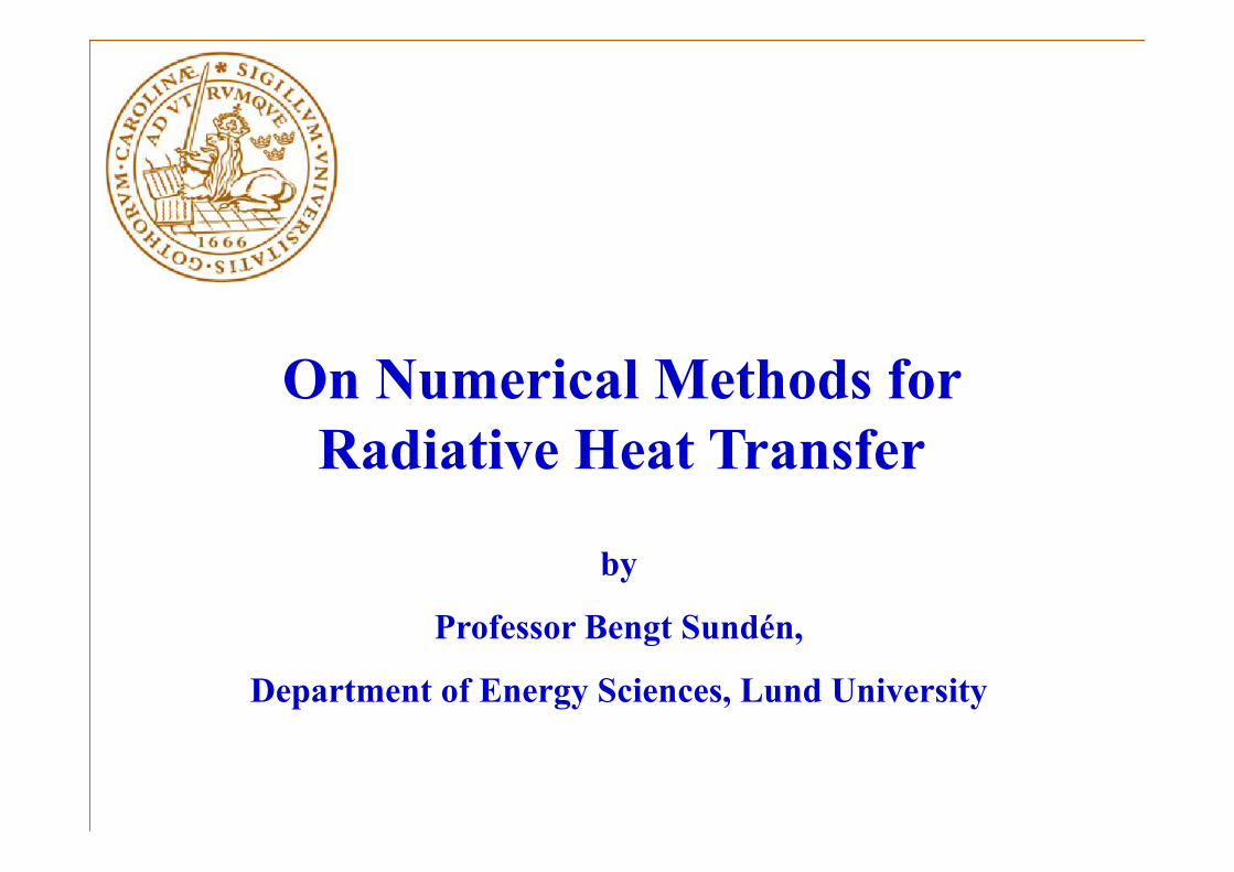
A principle sketch of the heat transfer mechanisms for a combustor liner for a gas turbine engine
Luminous radiation from soot particles Non-luminous radiation from gases

• Inhomogeneous medium• High temperature• High heat flux
Another Combustor
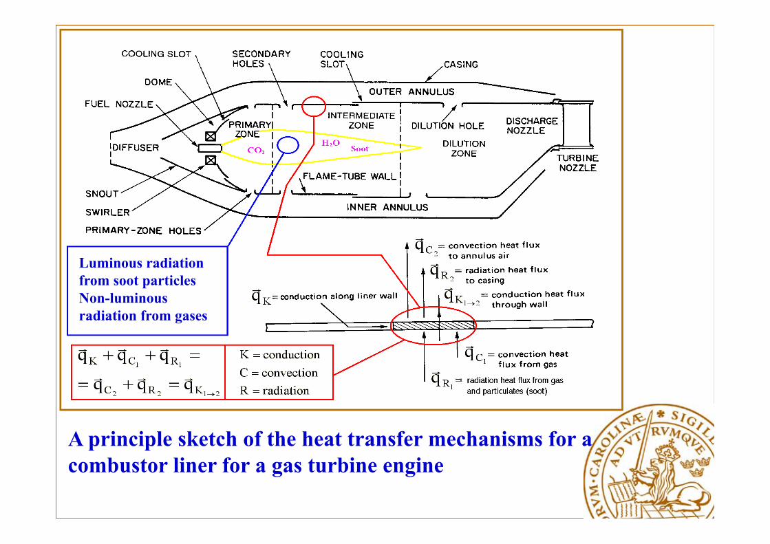
Sketch of grate furnace for biofuels combustion

Combustion zones in a grate furnace
Thermal Radiation – Radiative Heat Transfer
• Radiation without participating media» Surface radiation> Surface phenomena> No change in radiation intensity> Basic radiation quantity – emissive power> Analysis simple
Thermal Radiation – Radiative Heat Transfer
• Radiation with participating media» Gas and particle radiation> Volumetric phenomena> Change in radiation intensity> Basic radiation quantity – intensity of radiation> Analysis complex

Participating MediaCharacterization of the participating medium
• Absorption: attenuation of intensity→ absorption coefficient κ
• Emission: augmentation of intensity → absorption coefficient κ
• Scattering → sca ering coefficient σs, scattering albedo ω and scattering phase function ϕ- in-scattering: augmentation of intensity- out-scattering: attenuation of intensity

Radiation Parameters
• Extinction coefficient: β = κ + σsabsorption coefficient plus scattering coefficient
• Optical thickness:
• Scattering albedo: ω =
Radiative Heat Transfer Related to Combustion
What we need: radiation properties of combustion gases, coal and fly ash particles, small soot particlesSoot particles are produced in fuel-rich flames as a result of incomplete combustion of hydrocarbon fuels.Electron microscope studies show that soot particles are generally small and spherical of sizes 50 – 800 Å (0.005-0.08 μm). Volume fractions (fv) of soot in diffusion flames of hydrocarbons: 10-4 – 10-6
%
General considerations - 1
• Surface-to-surface radiation- no participating media → net exchange formulation based on radiosities, configuration factors (view factors) and surface properties: the general theory outlined in course MMV031 Heat Transfer – textbook ”B. Sunden, Introduction to Heat Transfer, WIT Press, UK, 2012”
General considerations - 2
• Radiation in participating media →Total Radiation Transfer Equation (RTE) –coupling with general energy equation for a fluid flow
RTE and how to solve it will be presented and exemplified
General considerations - 3
• Radiation in participating media →Simplified methods available for idealized cases – MMV031 Heat Transfer – Textbook ”B. Sunden, Introduction to Heat Transfer, WIT Press, UK, 2012”
Basic Features of Thermal Radiation Heat Transfer
Thermal radiation
4B TE
Stefan-Boltzmann’s law
81067.5 W/m2K4
Thermal Radiation
4TEg
gray body
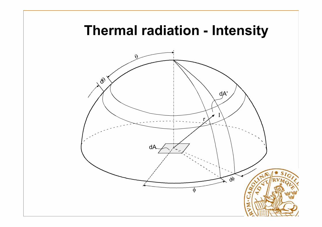
Thermal radiation - Intensity
d
Ir
dA
dA'
d
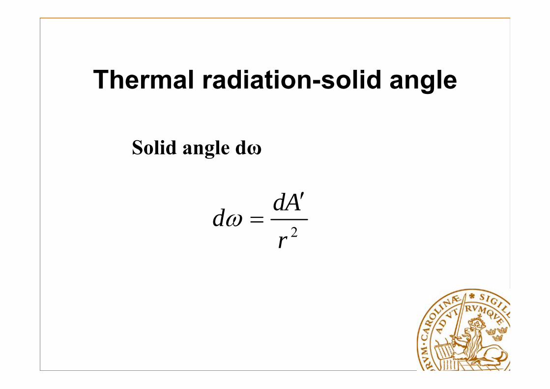
Thermal radiation-solid angle
2rAdd
Solid angle dω
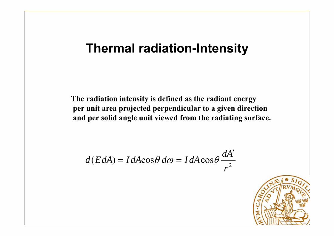
Thermal radiation-Intensity
2coscos)(
rAddAIddAIdAEd
The radiation intensity is defined as the radiant energyper unit area projected perpendicular to a given directionand per solid angle unit viewed from the radiating surface.
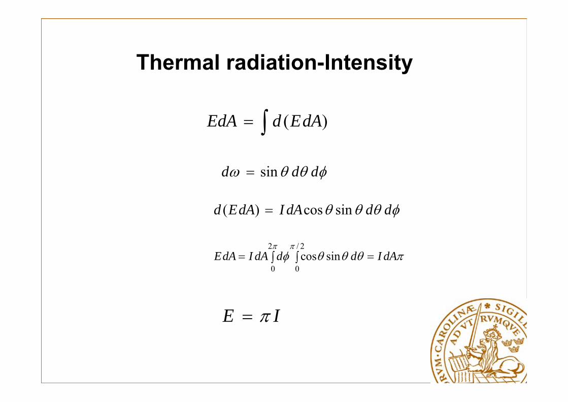
Thermal radiation-Intensity
)( dAEdEdA
ddd sin
dddAIdAEd sincos)(
2/
0
2
0sincos
dAIdddAIdAE
IE
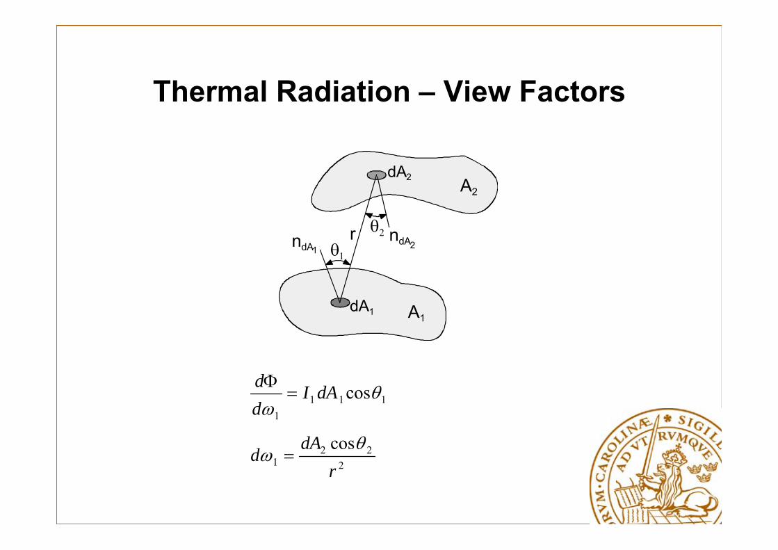
Thermal Radiation – View Factors
A2
A1dA1
dA2
ndA1ndA2
r
1111
cos
dAIdd
222
1cosr
dAd

Thermal Radiation – View Factors
,
1 2
21 21221
1coscos
A AAA dAdA
rI
11111AIAEA
121 12 AAA F
1 2
21221
112
coscos1
A A
dAdArA
F
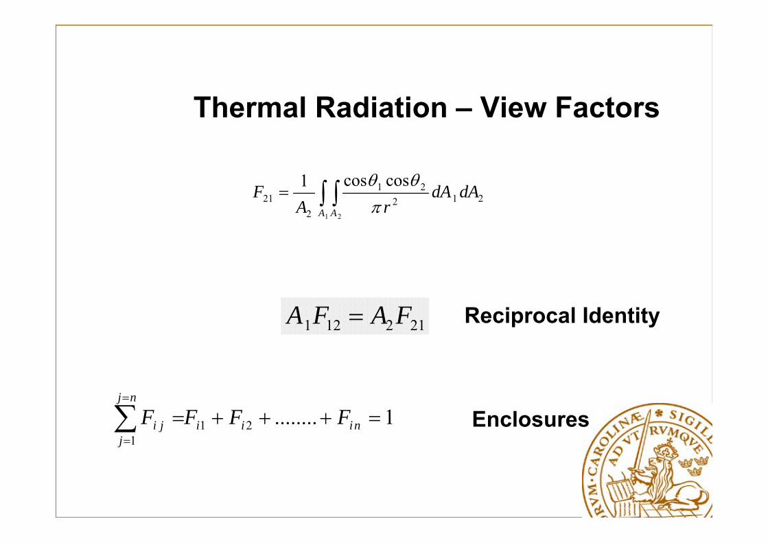
Thermal Radiation – View Factors
1 2
21221
221
coscos1
A A
dAdArA
F
212121 FAFA
1........211
niii
nj
jji FFFF
Reciprocal Identity
Enclosures

Thermal Radiation- Exchange Black Surfaces
Gi
Ji
i
k
iiii GJAQ
ii EJ ,B
k
ikkik
ikkkii FJAFJAGA

Thermal Radiation- Exchange Black Surfaces
)( k
kikiii JFJAQ
)()( ,B,B k
kikiik
kikiii EEFAJJFAQ
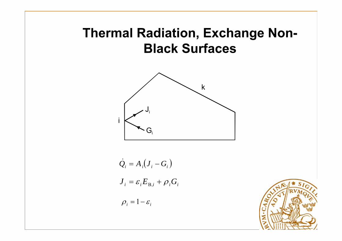
Thermal Radiation, Exchange Non-Black Surfaces
Gi
Ji
i
k
iiii GJAQ
iiiii GEJ ,B
ii 1

Thermal Radiation, Exchange Non-Black Surfaces
)(1 ,B ii
i
iii JEAQ
k
kikiii JJFAQ )(
Thermal Radiation, Exchange Non-Black Surfaces
Surface to Surface Radiative Heat Exchange ends up in a system of equations to be solved as radiosities are not known a priori, i.e., the equations on previous slide
Participating media
Elementary gases like H2, O2 and N2 emit almost nothermal radiation and are almost transparent ( = 1) forradiative transfer.
In engineering applications CO2 and H2O-steam are most important as these are good emitters and usually are present in high concentrations.CO, SO2 and CH4 are also good emitters but are usually present in small concentrations only.
Particles like soot may also contribute in the radiative exchange
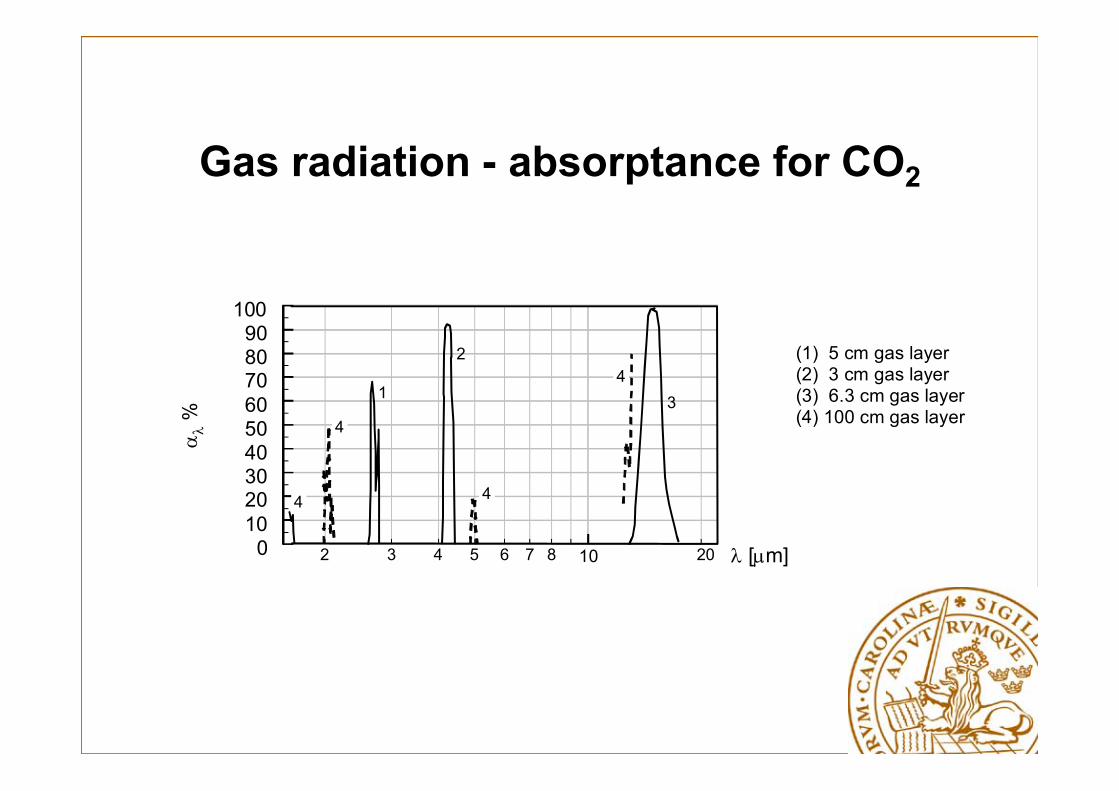
Gas radiation - absorptance for CO2
102 3 4 5 6 7 8 200102030405060708090
100
%
4
4
4
431
2
[m]
(1) 5 cm gas layer(2) 3 cm gas layer(3) 6.3 cm gas layer(4) 100 cm gas layer
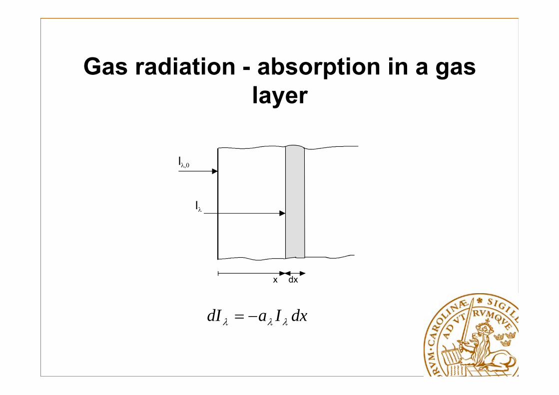
Gas radiation - absorption in a gas layer
x dx
I
I
dxIadI

Gas Radiation - absorption in a gas layer
a depends on pressure and temperature
If pressure and temperature are uniform, i.e., constant in the gas layer one has
,0a xI I e
Beer's law
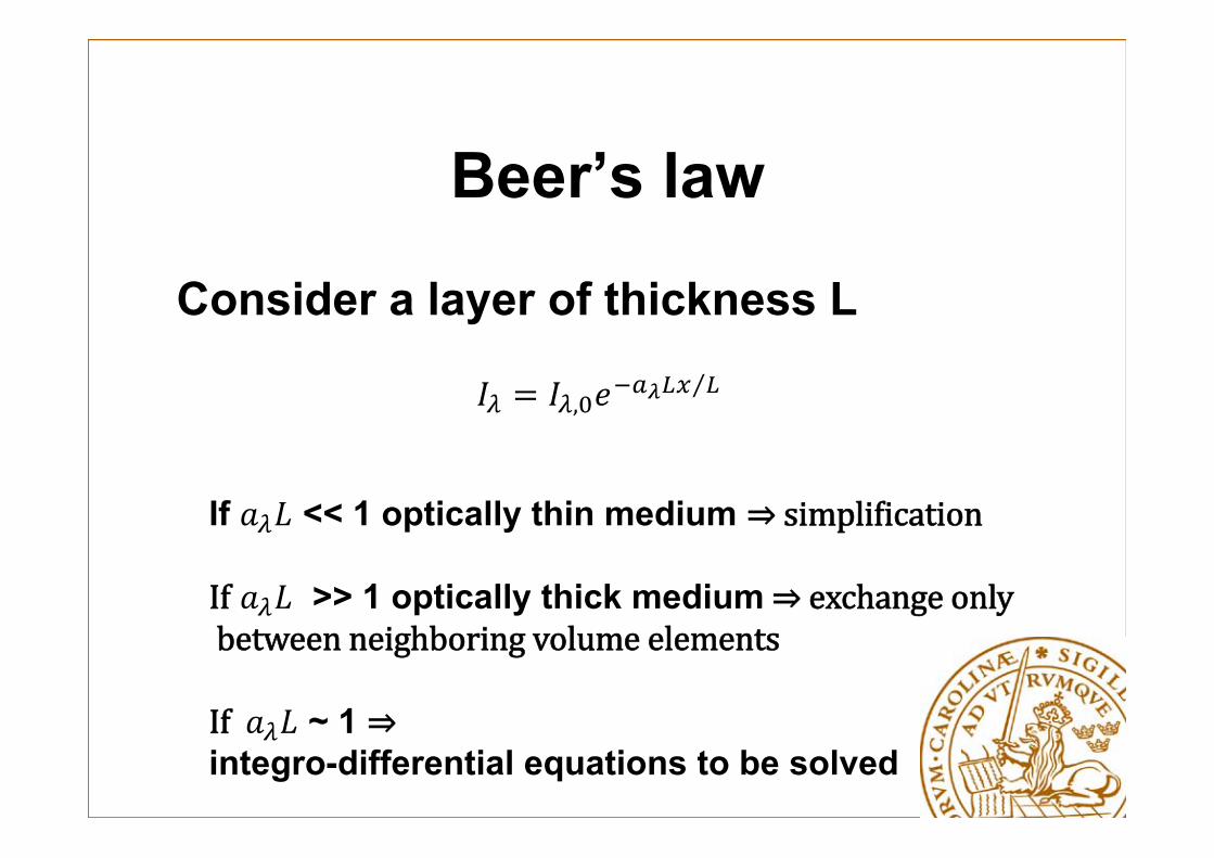
Beer’s law
Consider a layer of thickness L
,⁄
If << 1 optically thin medium ⇒simpli ication
If >> 1 optically thick medium⇒exchangeonlybetweenneighboringvolumeelements
If ~ 1 ⇒integro-differential equations to be solved
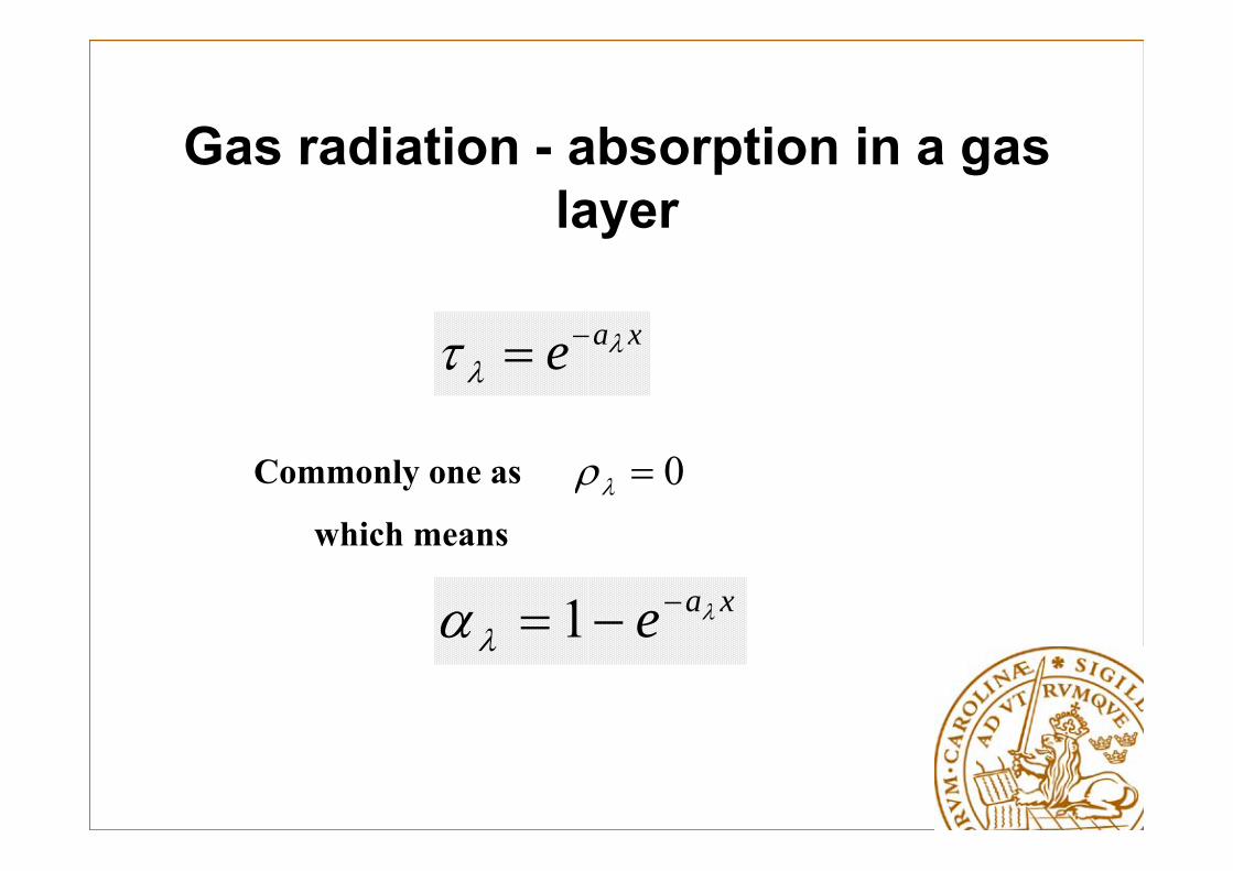
Gas radiation - absorption in a gas layer
xae
0Commonly one as
which means
xae
1
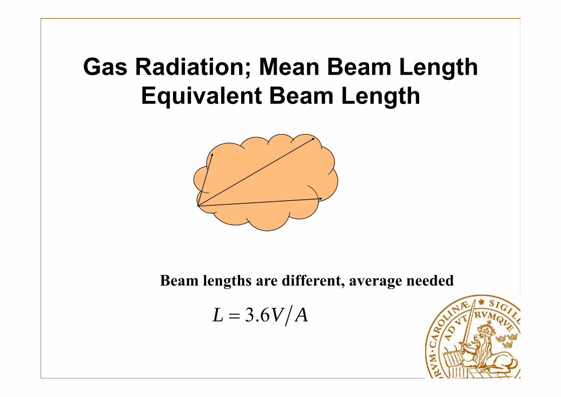
Gas Radiation; Mean Beam Length Equivalent Beam Length
AVL 6.3
Beam lengths are different, average needed

Gas Radiation, emittance for CO2
,
0.01
0.1
500 1000 1500 2000 2500
0.3
0.05
0.003
0.005
0.03
pCO2L = 105 Pa m6x104
3x10⁴
10 4
6x10³
3x10 3
1000
600
300100
60
30
Temperature [ K ]
2COε

Gas Radiation - emittance for CO2, pressure correction
pCO2L=8x10⁴ Pa m
3x10⁴
1.5x10⁴
8x10³
4x10³
1.5x10³
600
0.05 0.08 0.1 0.2 0.3 0.5 0.8 1.0 2.0 3.0 5.0
2.0
1.5
1.0
0.8
0.5
0.6
0.4
0.3
Total pressure atm
2COC

Gas Radiation; Heat Exchange between a Gas and a Chamber with Black Surfaces
emitted gas radiation – absorbed wall radiation
AQ

Radiative Exchange between a Gas and a Chamber with Black Surfaces
4wwg
4ggg )()( TTTT
AQ
OHCOwg 22)(T
)( gg T is determined at Tg
depends on both Tg and Tw
Detailed Analysis of Radiative Exchange in Participating Media
• Overall aim is to enable accurate heat load calculations
• Key is the so-called radiative transfer equation (RTE), plus
• Determine absorption coefficients for gases
• Determine scattering coefficients of particles

Radiation in Gases
•Gases, depending on the molecular structure,absorb and emit photons in some Vibration and/or Rotation bands. Each band consists of some absorption lines.
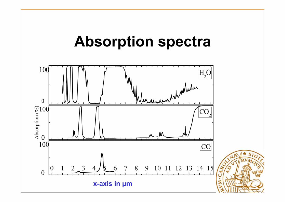
Absorption spectra
H2O
0
100
A
bsor
ptio
n (%
)
CO2100
0
0 1 2 3 4 5 6 7 8 9 10 11 12 13 14 15
CO100
0x-axis in μm

Importance and specifications
The products in combustion consist of gases such as carbon dioxide, water vapor, carbon monoxide etc., and in some cases consist of particles like soot, droplets, fly ash,…
The Importance of gas radiation in industry was recognized in the 1920,
The accurate prediction of radiative transfer problem not only depends on the solution method of the Radiative Transfer Equation (RTE), but also depends on models for determining the radiative properties!
General statements
• Empirical (analytical) models, preliminary design (50 - 100 K, deviation)
• Numerical models (CFD), detailed design
• Empirical models could give better results if parameters are tuned properly (by using, e.g., CFD)
• Many numerical models do not include soot
• Pressure and fuel type are important (soot formation)
• Empirical models use a luminosity factor to take care of the influence of soot
S1 0 0
Uj
h
Y
k
j
j j jt xS
U
x x
2 23 3
j kt ij ij
i j i k
U UP kx x x x
,R j
j
qPt x
kP
1 1 2 2kf C P f Ck k
2 /t f C k
t
/ /t tPr Pr
/ /t tSc Sc
/t k
/t
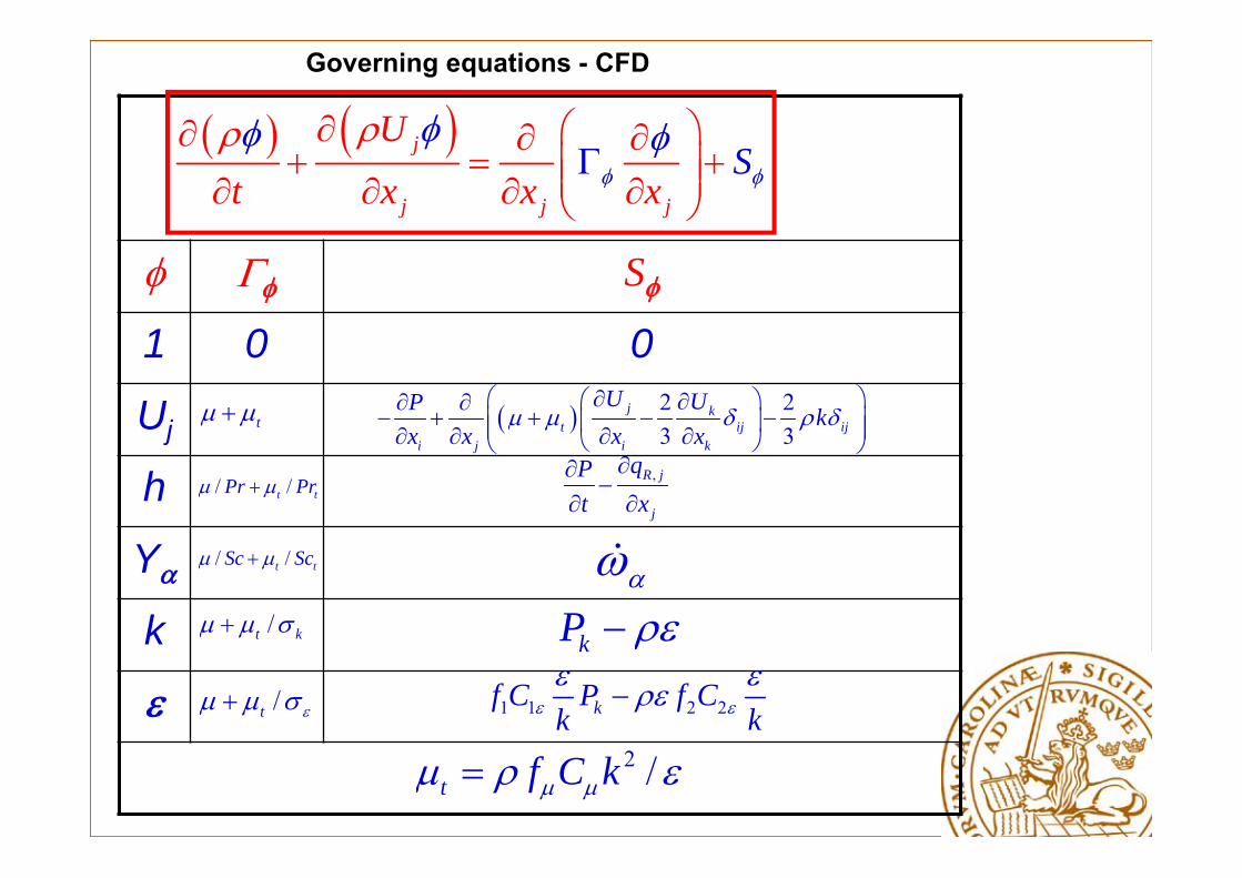
Governing equations - CFD
RTE-radiative transfer equation
•Will provide source term in energy equation
• Radiation may be important depending on pressure and fuel used in the combustion chamber
• Good predictions of the RTE will give better predictions of the temperature and flow fields and accordingly heat load calculations
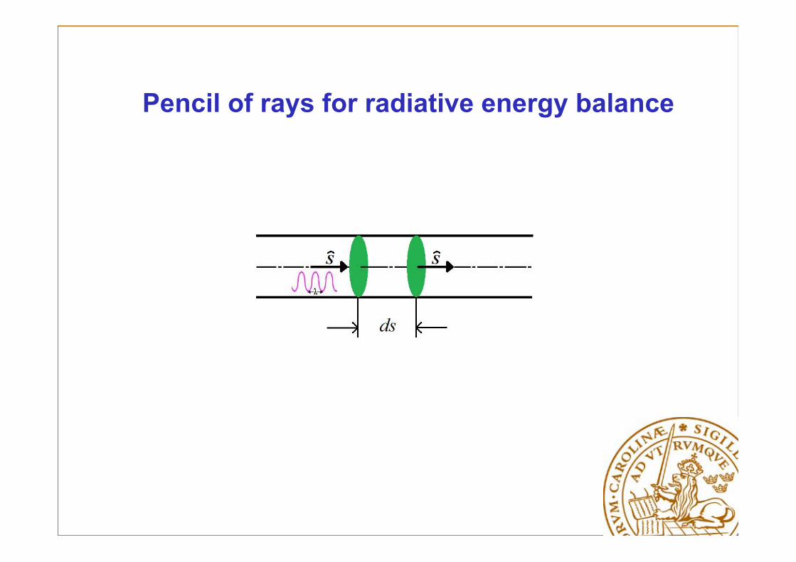
Pencil of rays for radiative energy balance
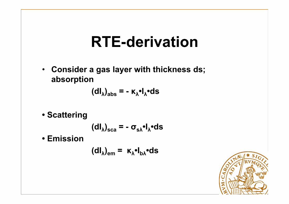
RTE-derivation• Consider a gas layer with thickness ds;
absorption(dIλ)abs = - κλ•Iλ•ds
• Scattering(dIλ)sca = - σsλ•Iλ•ds
• Emission(dIλ)em = κλ•Ibλ•ds
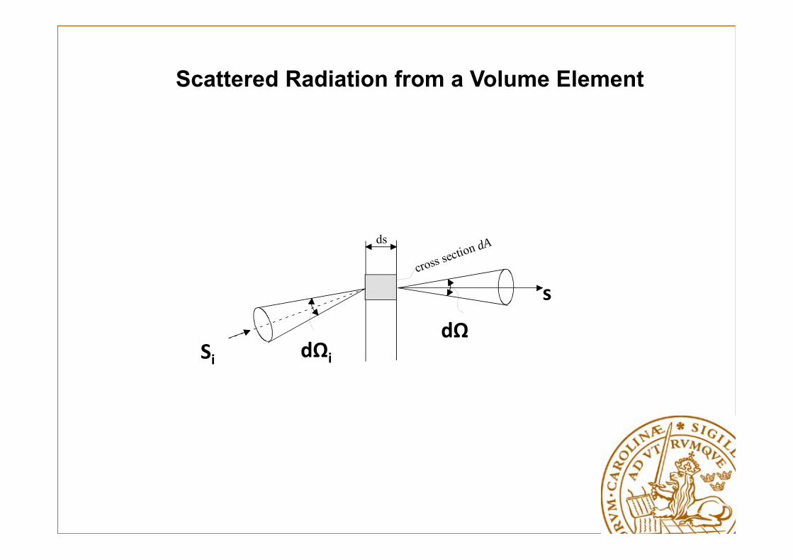
cross section dAds
s
SidΩ
dΩi
Scattered Radiation from a Volume Element
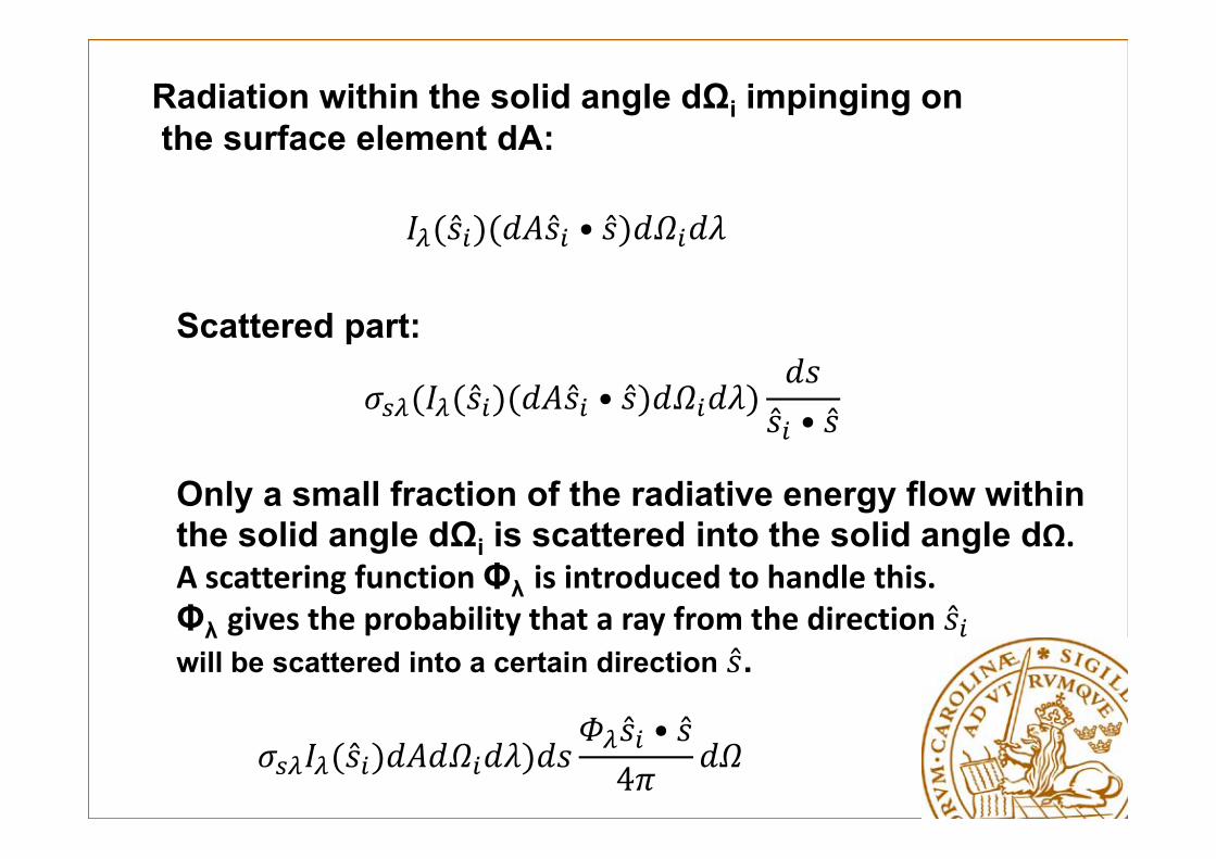
Radiation within the solid angle dΩi impinging onthe surface element dA:
•
Scattered part:
• •
Only a small fraction of the radiative energy flow within the solid angle dΩi is scattered into the solid angle dΩ.A scattering function Φλ is introduced to handle this.Φλ gives the probability that a ray from the direction will be scattered into a certain direction .
• 4

4ˆˆ ˆ ˆ( ) = ds ( ) ( ,s)
4s
i sca i i idI s I s s d
By integrating the previous equation overall incident directions, the total in-scattered radiative energy into a solid angle dΩ becomes
For isotropic scattering, Φλ = 1

Pencil of rays for radiative energy balanceEnergy Balance for thermal radiation propagating in a direction s
Out - In = emission-absorption-scattering (away) + all in scattering

• Energy Balance for thermal radiation propagating in a direction s
4ˆˆ ˆ ˆ ˆ ˆ ˆ( , , ) I ( , , ) ( , ) ( , , ) ( , , ) ( ) ( ,s)
4s
b s b i i iI s ds s t dt s s t I s t ds I s s t ds I s s t ds I s s d ds
By introducing c = ds/dt one can find
4
1 1 ˆ
ˆ ˆ ˆ( ) ( , )4
b
si i i
I I I I I Ic t s c t
I d
s
s s s

Radiative Transfer Equation, RTE (omitted transient term)
4
ˆ ˆ ˆ ˆ( ) ( , )4
sb i i i
dI I I I I dds
s s s s
βλ = κλ + σsλ

Divergence of the Radiative Heat Flux
yx zqq q dxdydz dV
x y z
q
( , , )x y zq q qq
Net heat flux into volume element

Divergence of radiative heat flux
4 4 4 4
ˆ ˆ ˆ ˆ ˆ4 ( ) ( ) ( , )4
sb i i iI d I I d I d d
s s s s s
4
ˆI d
q s
4
ˆ ˆ( , ) 4i d
s s

Divergence of radiative heat flux
s
4
4 4b bI I d I G
q
with
where Gλ is the irradians
For a gray medium κλ = κ
4 2 4
4
4 4T Id n T G
q

The Complete Energy Equation
pT T T Tc u v wt x y z
q
conduction radiation radiationk T q q q q
radiationq according to previous slide
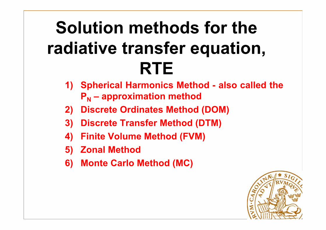
Solution methods for the radiative transfer equation,
RTE1) Spherical Harmonics Method - also called the
PN – approximation method2) Discrete Ordinates Method (DOM)3) Discrete Transfer Method (DTM)4) Finite Volume Method (FVM)5) Zonal Method6) Monte Carlo Method (MC)
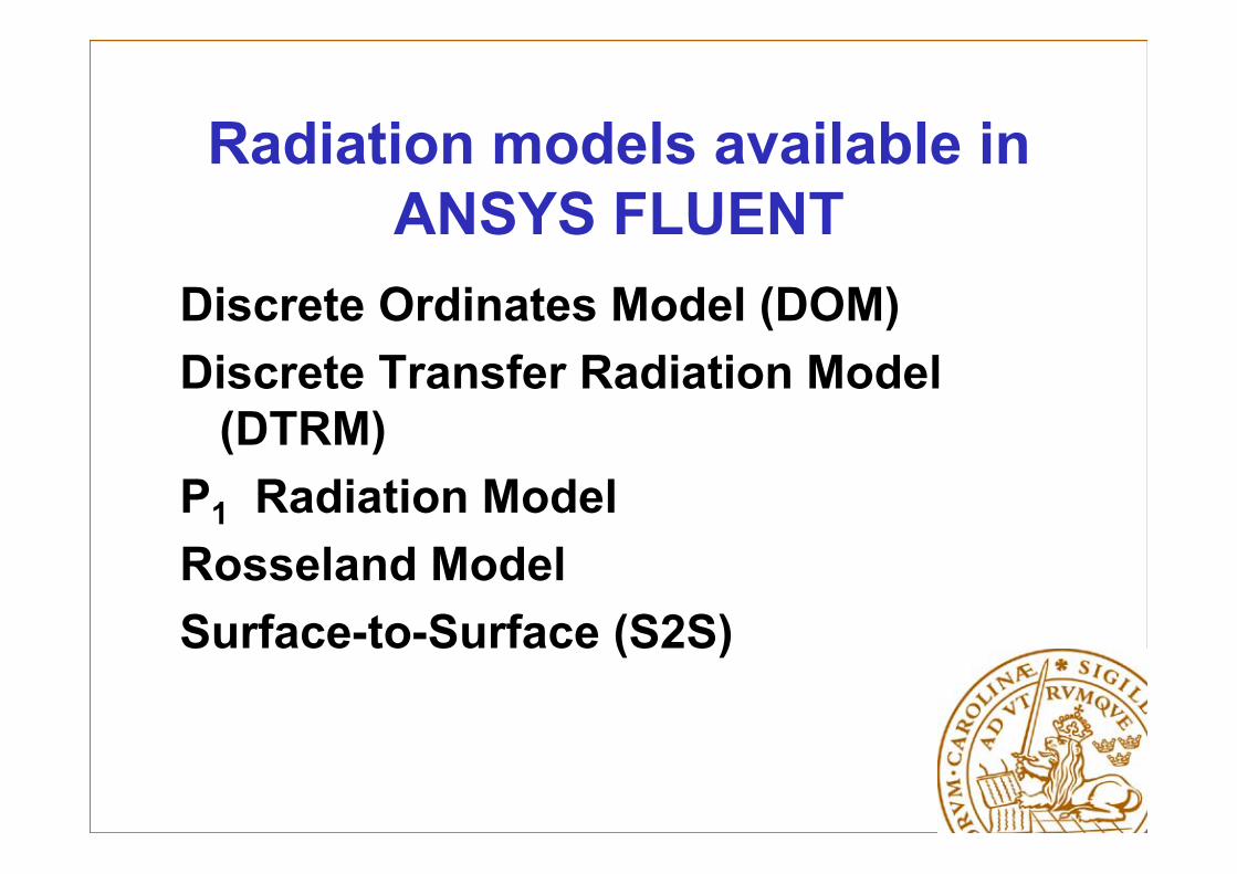
Radiation models available in ANSYS FLUENT
Discrete Ordinates Model (DOM)Discrete Transfer Radiation Model
(DTRM)P1 Radiation ModelRosseland ModelSurface-to-Surface (S2S)

Radiation models – general advices for selection
• Low computational effort with reasonable accuracy: P1
• Accuracy: DTRM and DOM• Optical thin media: DTRM and DOM• Optical thick media: P1
• Scattering: P1 and DOM• Localized heat sources/sinks: DTRM,
DOM with large number of rays or ordinates

RTE coupling with Energy Equation
Energy equation
RTE
NS-equations
2 44R RS divq n T G
Species equations

Radiative Transfer Equation (RTE)
iiis
sb dsssIIIIsI
tI
c
)ˆ,ˆ()ˆ(4
1
4
Solution of RTE requires the absorption coefficient ()
and scattering coefficient s

Brief descriptions of methods to solve the RTE

Rosseland ModelIf the participating medium is optically thick, it is possible to simplify the numerical simulations by means of the so-called
Rosseland approximation.Instead of solving an equation for G (the irradiance), it is possible
to assume a theoretical value prescribed by the black body expression and then to group the consequent radiation terms in
some modified transport coefficients for the energy eqution:
16

Differential Approximation (PN)• The basic idea is that the intensity in a participating
medium can be represented as a rapidly converging series whose terms are based on orthogonal spherical harmonics. Usually a small number is adequate (P1, P3, ...). For the P1 approximation only zeroth and first order moments of the intensity are considered.
• Essentially the deviation of the local intensity from its local mean value is expressed in terms of local gradients. This allows derivation of a diffusion expression for the radiation flux and consequently the derivation of an advection-diffusion equation for the local mean intensity.

The P1 radiation modelThe directional dependence in the RTE is integrated outRTE becomes easy to solve with limited CPU demandEffects of scattering by particles, droplets and soot can
be includedWorks well where the optical thickness is large (e.g.,
combustion)The limitations are: All surfaces are assumed to be
diffuse, less accurate for small optical thickness, may overpredict the radiative fluxes from localized heat sources and sinks.

The P1 radiation model• The P1, model solves an advection-diffusion
equation for the mean local incident radiation (irradiance) G
• Consequently the gradient of the radiation flux can be directly substituted into the energy equation to account for heat sources or sinks due to radiation
4
• 4 0
Hottel’s zonal method• The equations for emitting and absorbing media
can be easily solved and find the conditions leading to a uniform temperature distribution within a medium being bounded by infinite parallel black walls.
• Then it is always possible to subdivide the generic domain into isothermal zones of appropriate shape such that the constant stepwise profile approximates the actual solution. The analysis, i.e., Hottel’s method, allows to recover the consistent thermal fluxes at the boundaries of the arbitrary zones.
Discrete Ordinates Model (DO or DOM)• The RTE is solved for a discrete number of finite
solid angles• The method is conservative which means that
heat balance is achieved even for coarse discretization
• Accuracy is increased by using a finer discretization
• Accounts for scattering, semi-transparent media, specular surfaces and wavelength-dependent transmission using banded-gray option
• CPU intensive

Angular discretization - DOM

Discrete Transfer Radiation Model (DTRM or DTM)
• It assumes that radiation leaving a surface element within a specified range of solid angles can be approximated by a single ray.
• It uses a ray-tracing technique to integrate radiant intensity along each ray.
• Relatively simple model• Accuracy can be increased by increasing the
number of rays• Can be applied to a wide range of optical
thicknesses• It assumes that all surfaces are diffuse• Effect of scattering not included• CPU intensive if a large number of rays are used

DTRM-Ray arriving at an surface element Q
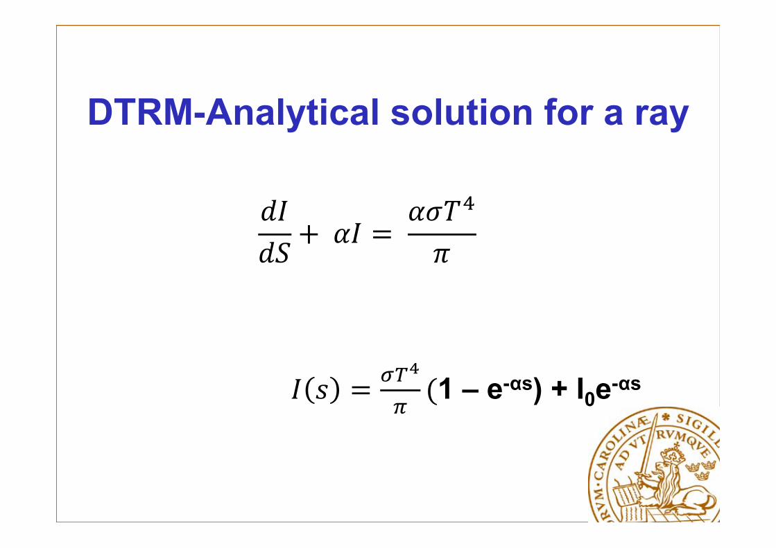
DTRM-Analytical solution for a ray
1 – e-αs) + I0e-αs
DTRM
• The method as it was originally proposed consists of determining the intensity for each of N (Nφ x Nθdiscretized angles) rays arriving at each surface element Q in an enclosure as shown in previous Fig.
• The ray and its associated solid angles are equally distributed over the surface of a hemisphere centred over the receiving element, rather than being chosen and weighted through a quadrature technique as for the DOM.

• Radiative Properties of Gases
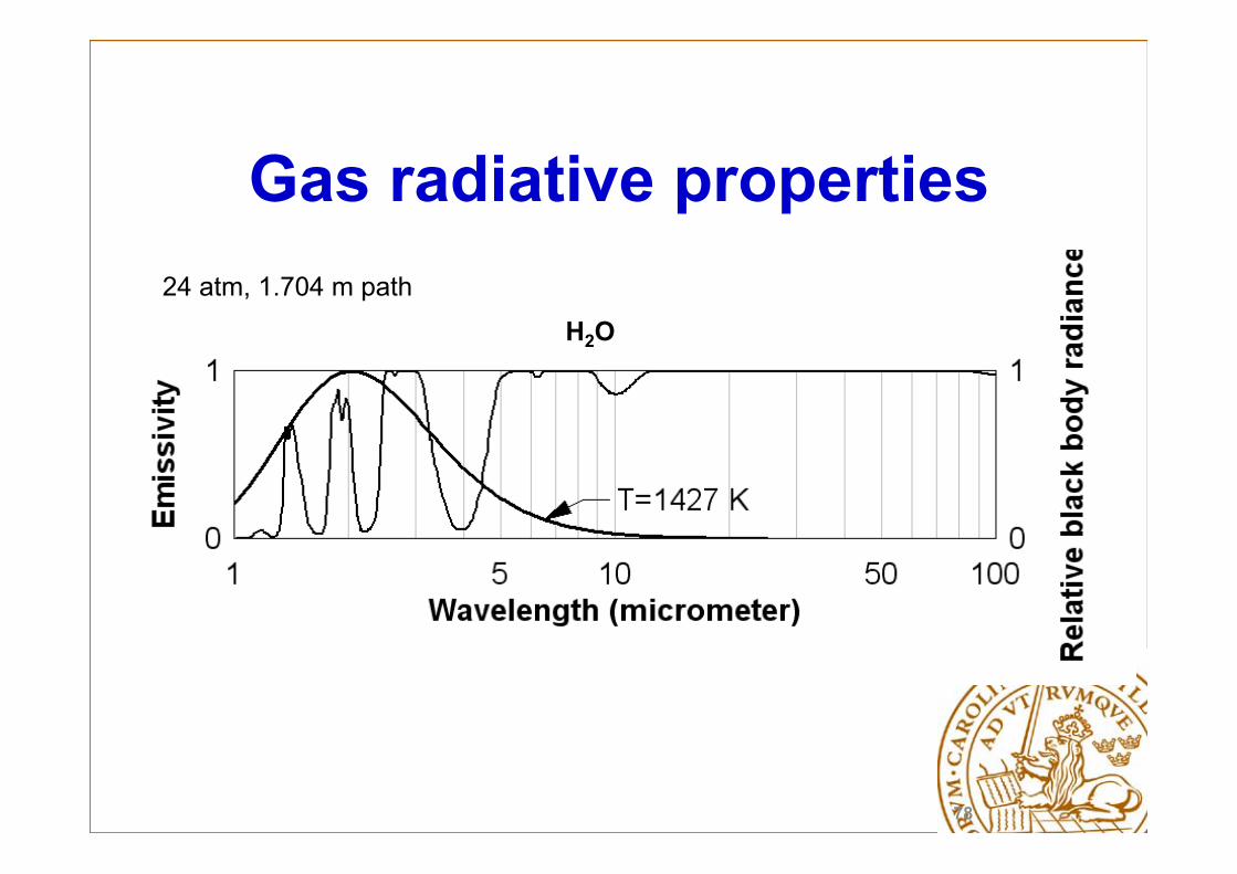
Gas radiative properties
H2O24 atm, 1.704 m path
78
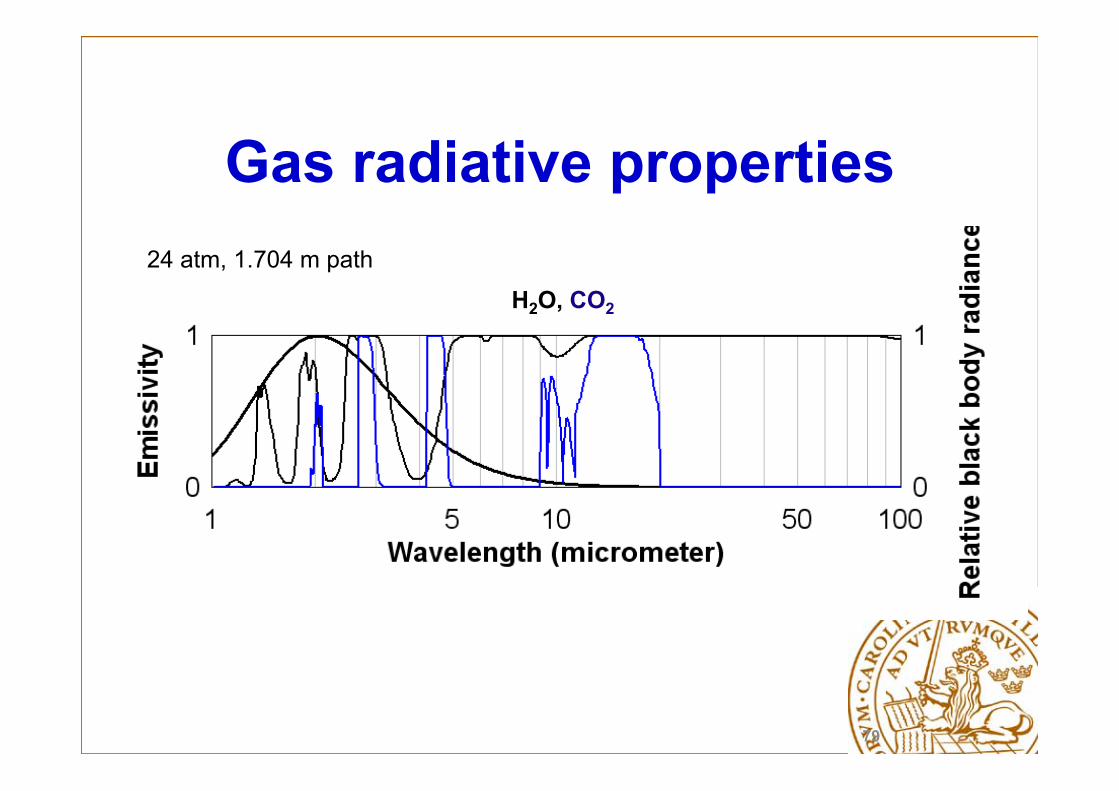
Gas radiative properties
H2O, CO2
24 atm, 1.704 m path
79

H2O, CO2, CO
Line overlapping and broadening
24 atm, 1.704 m path
4,3 µm
4,7 µm
6,3 µm
80

H2O, CO2, CO
Gas radiative properties
24 atm, 1.704 m path
81

Importance of CO
Position c, 24 atm
24 atm, 1.704 m path
82

On importance of CO
•CO radiation can make substantial contribution to radiation in combustion environments with high CO concentration
•The CO contribution to the total radiative heat flux increases with decreasing pressure
•The line overlapping between radiative species decreases as pressure decreases
83

Models for radiative properties: importance and specifications
Modelling of radiative properties in the infrared region with sufficient accuracy,
Compatibility with selected RTE solver,
Capability to handle non-homogeneous cases,
Small database,
Low computational efforts.

Radiative Properties of Gases
• Line-By-Line (LBL)• Gray Gas (GG) models• Spectral models; Statistical Narrow
Band Models (SNB) (with a correlated k-distribution method (CK)), Wide Band models (WB), Weighted-Sum-of-Gray-Gases (WSGG), Spectral-Line-Weighted-sum-of-gray-gases (SLW), Wide Band Correlated k-model (WBCK)
Prediction of Radiation in Gases
• Empirical - Based on measurements of Total Emissivity • Less sophisticated, more engineering approaches
• Line by line calculations (Spectroscopic databases)
• Numerical Band models (Narrow bands, Wide bands, ..)
• Correlation models (Weighted Sum of Grey Gases, …)
EWBM (exponential wide band model)
Advantages: Experimental base and wide range of application,
Small database and fairly less computational efforts,
Possibility for utilization in nonhomogeneous mixtures.
Deficiencies: Calculates band absorptance and band transmissivity,
Can not be used in reflective walls and scattering media,
Low accuracy.
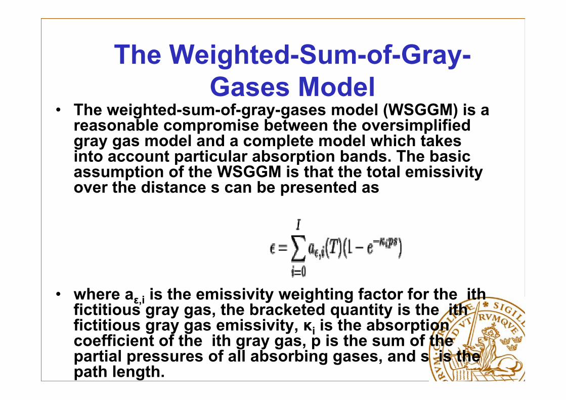
The Weighted-Sum-of-Gray-Gases Model
• The weighted-sum-of-gray-gases model (WSGGM) is a reasonable compromise between the oversimplified gray gas model and a complete model which takes into account particular absorption bands. The basic assumption of the WSGGM is that the total emissivity over the distance s can be presented as
• where aε,i is the emissivity weighting factor for the ithfictitious gray gas, the bracketed quantity is the ithfictitious gray gas emissivity, κi is the absorption coefficient of the ith gray gas, p is the sum of the partial pressures of all absorbing gases, and s is the path length.
Spectral-Line-Weighted-sum-of-gray-gases-model (SLW)
• The SLW might be regarded as an improved WSGG model, obtained from line-by-line spectra of the absorbing species.
• SLW-x where x is the number of gray gases considered.
Wide Band Correlated-k model (WBCK)
• WB models yield transmittances and cannot be easily coupled to differential solutions methods of the RTE.
• WBCK gives an absorption coefficient for each spectral interval. The weight of each spectral interval is calculated from the blackbody fraction of the interval.
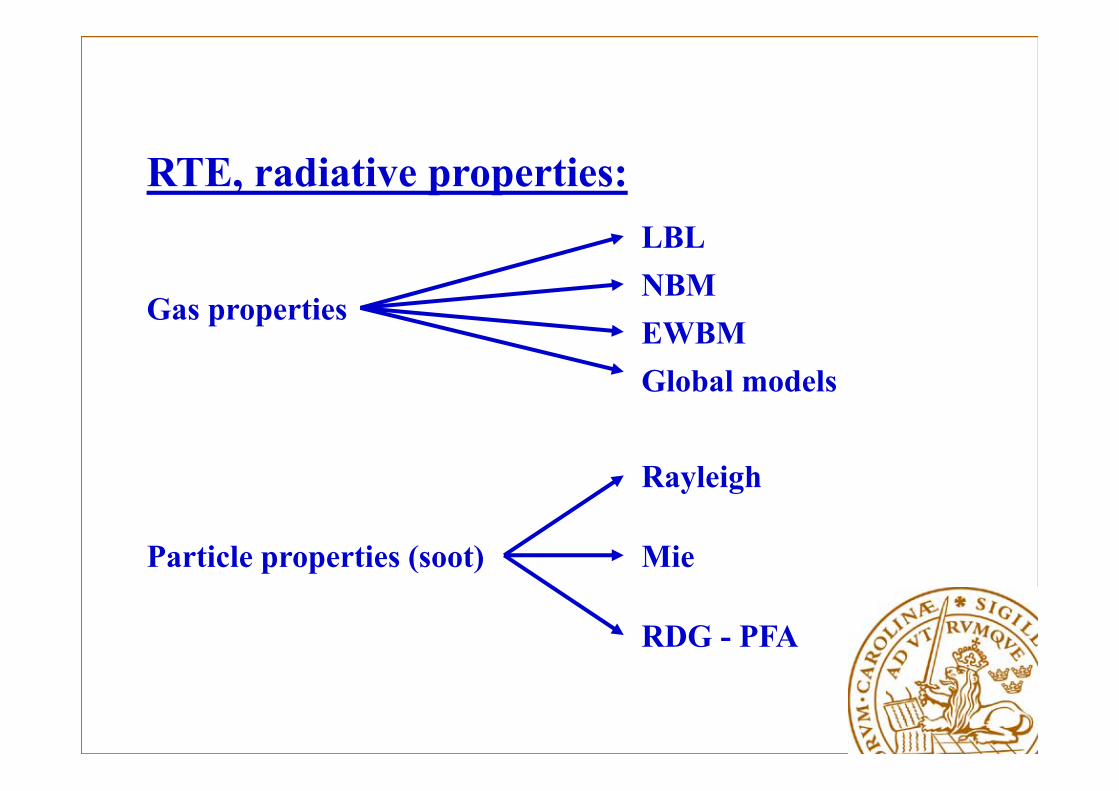
RTE, radiative properties:
Gas properties
Particle properties (soot)
Rayleigh
Mie
RDG - PFA
LBLNBMEWBMGlobal models
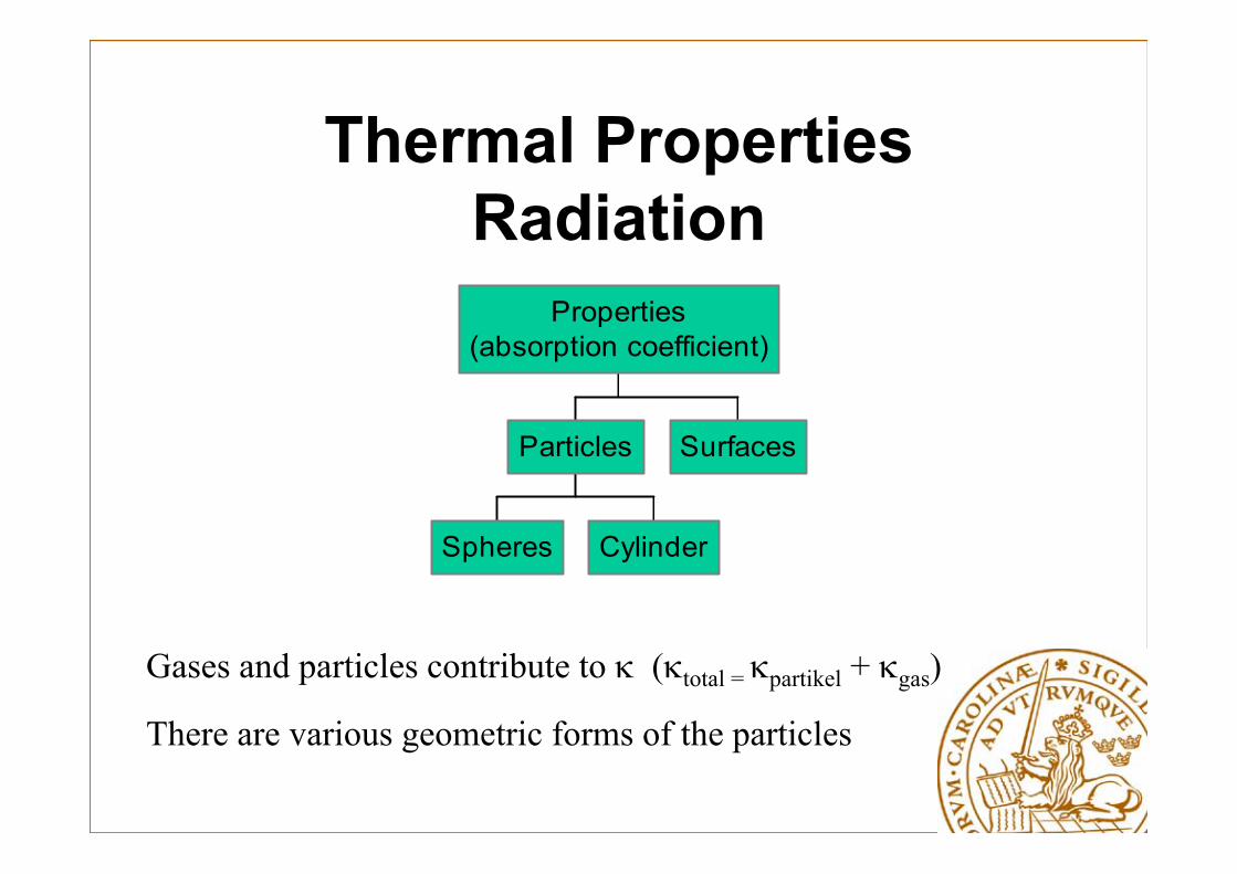
Thermal Properties Radiation
Spheres Cylinder
Particles Surfaces
Properties(absorption coefficient)
Gases and particles contribute to (total = partikel + gas)
There are various geometric forms of the particles
Type of Particles
Analysis of ash samples from cyclones and Electro-Static Precipitator (ESP) in a grate biomass boiler, fueled by bark and wood chips, shows:
• The fly-ash and char are the main particles, and
• The ratio of fly-ash and char to total amount of ash is 0.72 and 0.28, respectively.
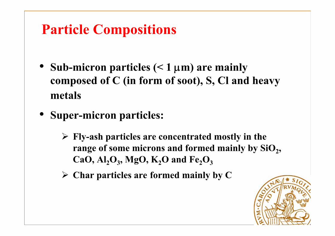
Particle Compositions
• Sub-micron particles (< 1 m) are mainly composed of C (in form of soot), S, Cl and heavy metals
• Super-micron particles:
Fly-ash particles are concentrated mostly in the range of some microns and formed mainly by SiO2, CaO, Al2O3, MgO, K2O and Fe2O3
Char particles are formed mainly by C
Study of effects of particles on radiative heat transfer in biomass boilers
• Determining types and amounts of particles.
• Prediction of non-gray radiative properties and accurate phase functions, and
• Evaluation of particle effects on radiative heat transfer by designated test cases.
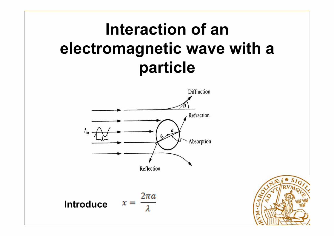
Interaction of an electromagnetic wave with a
particle
Introduce
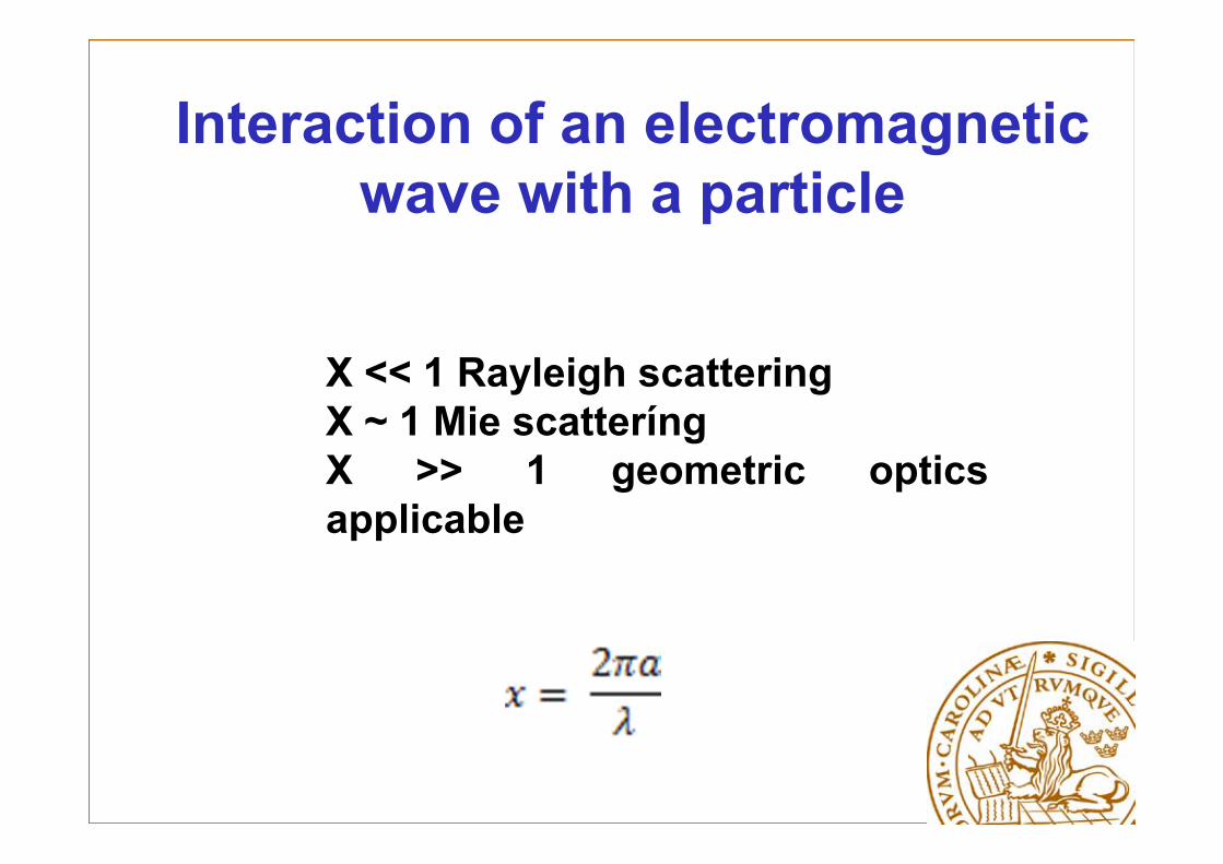
Interaction of an electromagnetic wave with a particle
X << 1 Rayleigh scatteringX ~ 1 Mie scatteríngX >> 1 geometric opticsapplicable
98/21
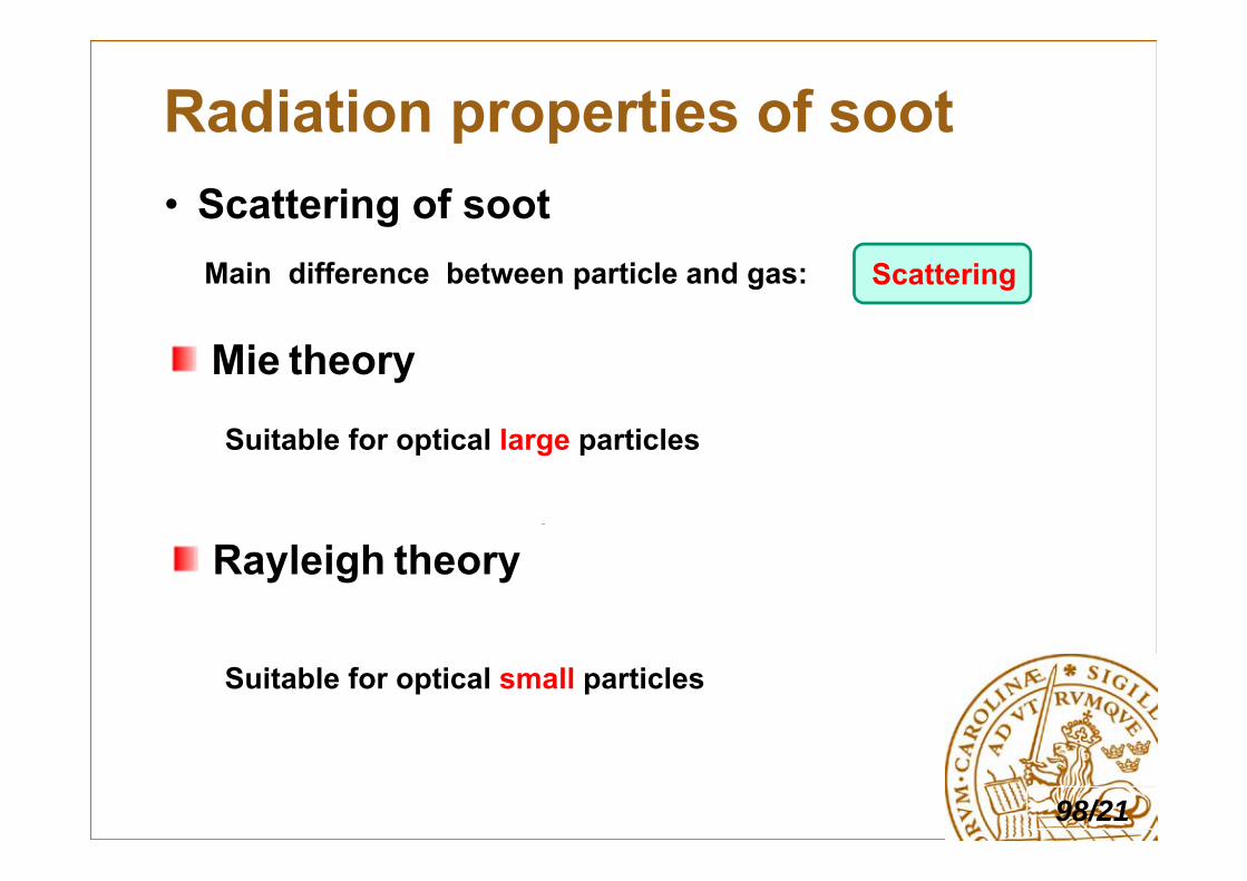
• Scattering of soot
Radiation properties of soot
μm
Main difference between particle and gas: Scattering
Mie theory
Rayleigh theory
Suitable for optical large particles
Suitable for optical small particles

Selected Methods
• Using measured data and statistical methods
• Investigation of composition of particles,• Applying the Mie scattering theory,
• Summarizing the data from the Mie calculations by using statistical distributions.
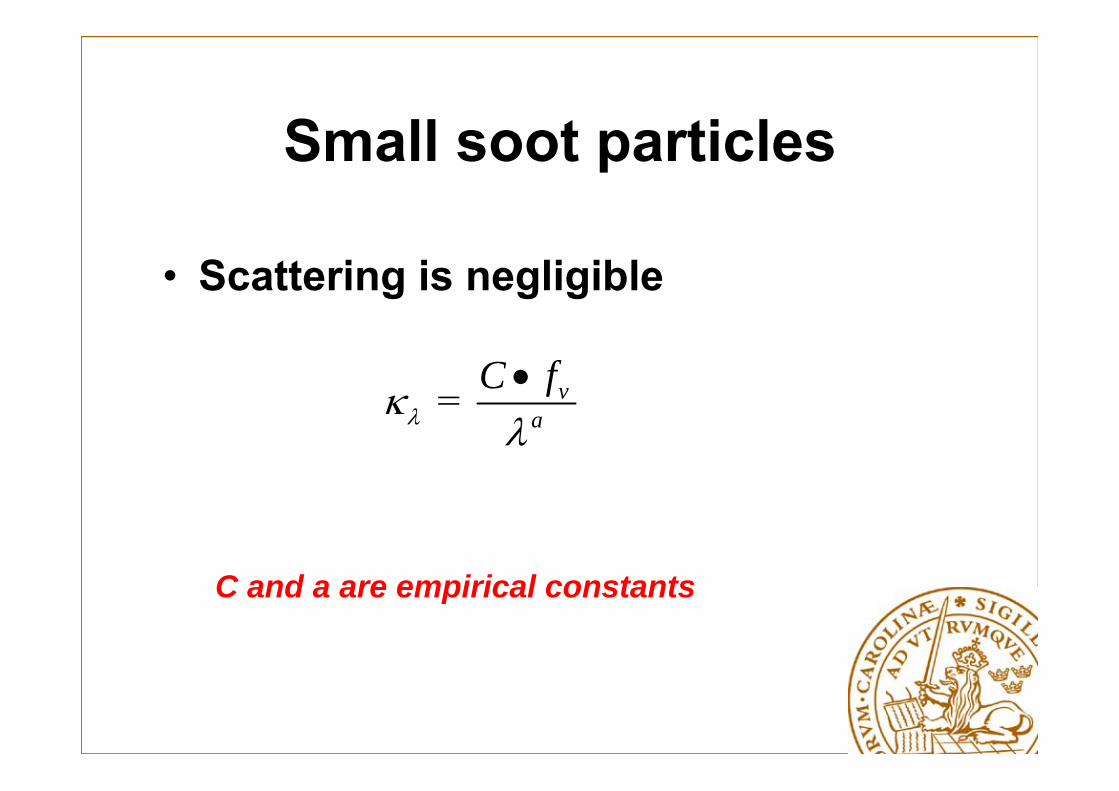
Small soot particles
• Scattering is negligible
= va
C f
C and a are empirical constants
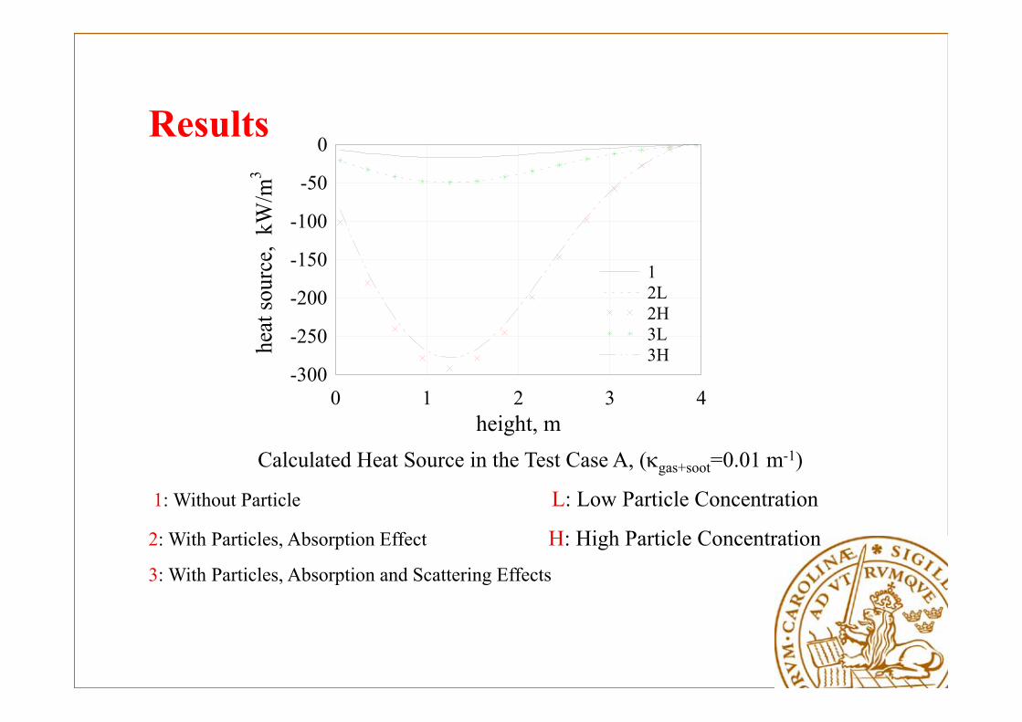
Results
height, m
heat
sour
ce,
kW/m
3
0 1 2 3 4-300
-250
-200
-150
-100
-50
0
12L2H3L3H
Calculated Heat Source in the Test Case A, (gas+soot=0.01 m-1)
1: Without Particle L: Low Particle Concentration
2: With Particles, Absorption Effect H: High Particle Concentration3: With Particles, Absorption and Scattering Effects

On Solution of the RTE
• Different radiation models will give different results
• Some radiation models are better suited for different situations, see next table
• Good if solution method of RTE is compatible with that of other equations
• Be able to handle scattering (due to soot agglomerates)
• Be able to handle spectral calculations
• Be able to handle complex geometries
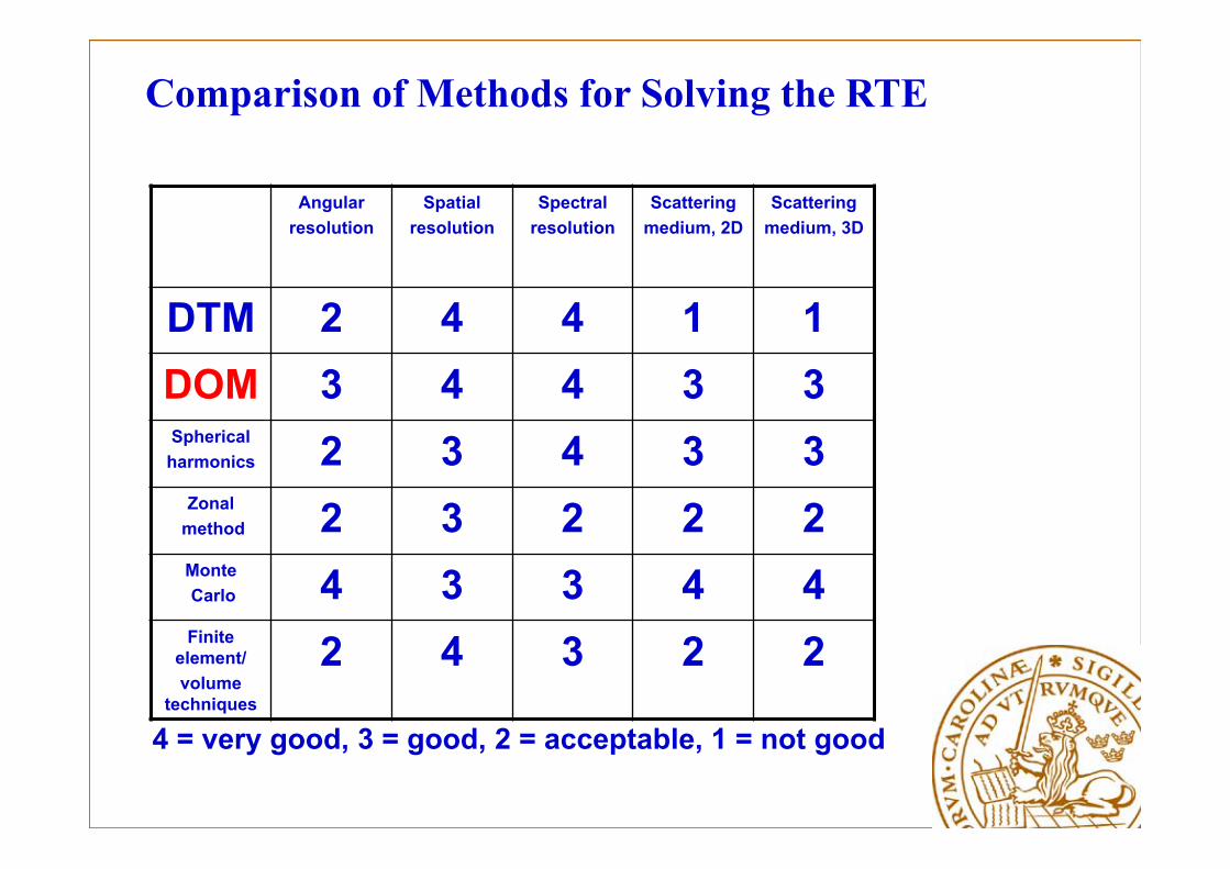
Comparison of Methods for Solving the RTE
Angular resolution
Spatialresolution
Spectral resolution
Scattering medium, 2D
Scattering medium, 3D
DTM 2 4 4 1 1DOM 3 4 4 3 3Spherical harmonics 2 3 4 3 3
Zonalmethod 2 3 2 2 2MonteCarlo 4 3 3 4 4Finite
element/volume
techniques
2 4 3 2 2
4 = very good, 3 = good, 2 = acceptable, 1 = not good
Applications of Radiative Heat Transfer with Participating Media
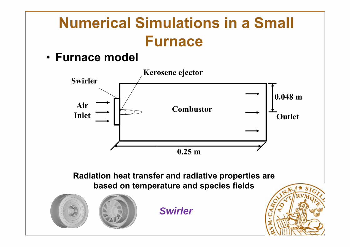
• Furnace model
Numerical Simulations in a Small Furnace
μm
Radiation heat transfer and radiative properties are based on temperature and species fields
Combustor
0.25 m
AirInlet
SwirlerKerosene ejector
0.048 m
Outlet
Swirler

• Volume flow rate of air 31.6 m3/h • Volume flow rate of kerosene 6.6 litre/h• DOM (the so-called S8 model was used)• SNB for CO2 and H2O

Results
9/16
Flow field - Fluent results
The flow in the furnace is very non-homogeneous and complex as it passes the swirler
a) Temperature b) Pressure (+101325Pa)
c) Mole fraction of H2O
d) Mole fraction of CO2

Numerical Simulation in a Small Furnace
a) With scattering b) Without scattering
• Soot radiation contribution(a)
W/m
(b)
W/m
Participating media are gases H2O, CO2, CO and soot

Numerical Simulation in a Small Furnace
a) Radiative Heat Flux b) Radiation Contribution
• Soot radiation contribution
0.00 0.05 0.10 0.15 0.20 0.25 0.3005
10152025303540
z (m)
Rad
iatio
n he
at fl
ux (k
w/m
2 )
Two gases Three gases Soot-With scattering Soot-Without scattering
(a)
0.00 0.05 0.10 0.15 0.20 0.25 0.300
5
10
15
20
25
30
35
Rad
iatio
n C
ontri
butio
n (%
)
z (m)
Soot-With scattering Soot-Without scattering
(b)
Soot has a big influence on the radiative heat fluxScattering has no influence on the radiative heat flux
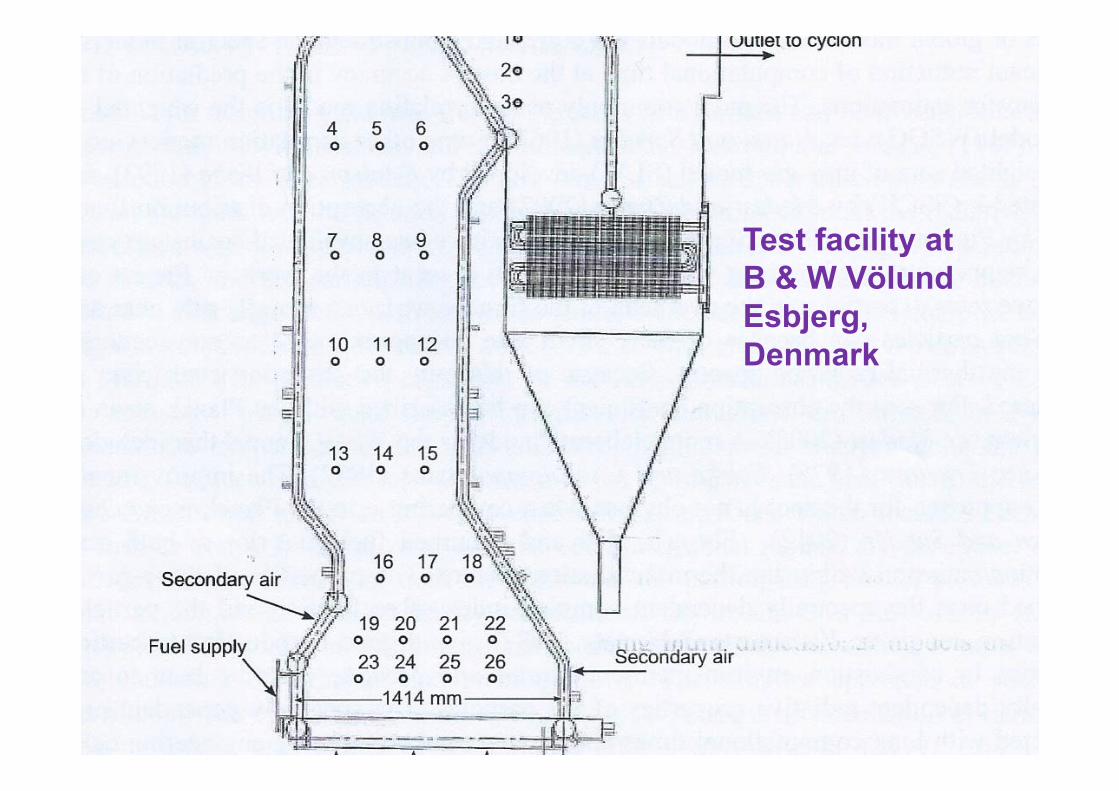
Test facility atB & W VölundEsbjerg, Denmark
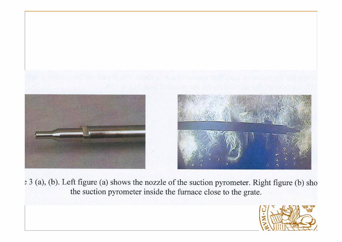

Pellets in the tests
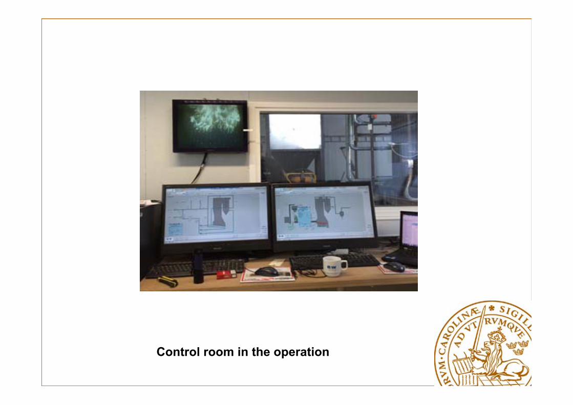
Control room in the operation
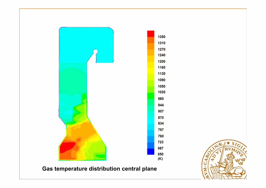
Gas temperature distribution central plane
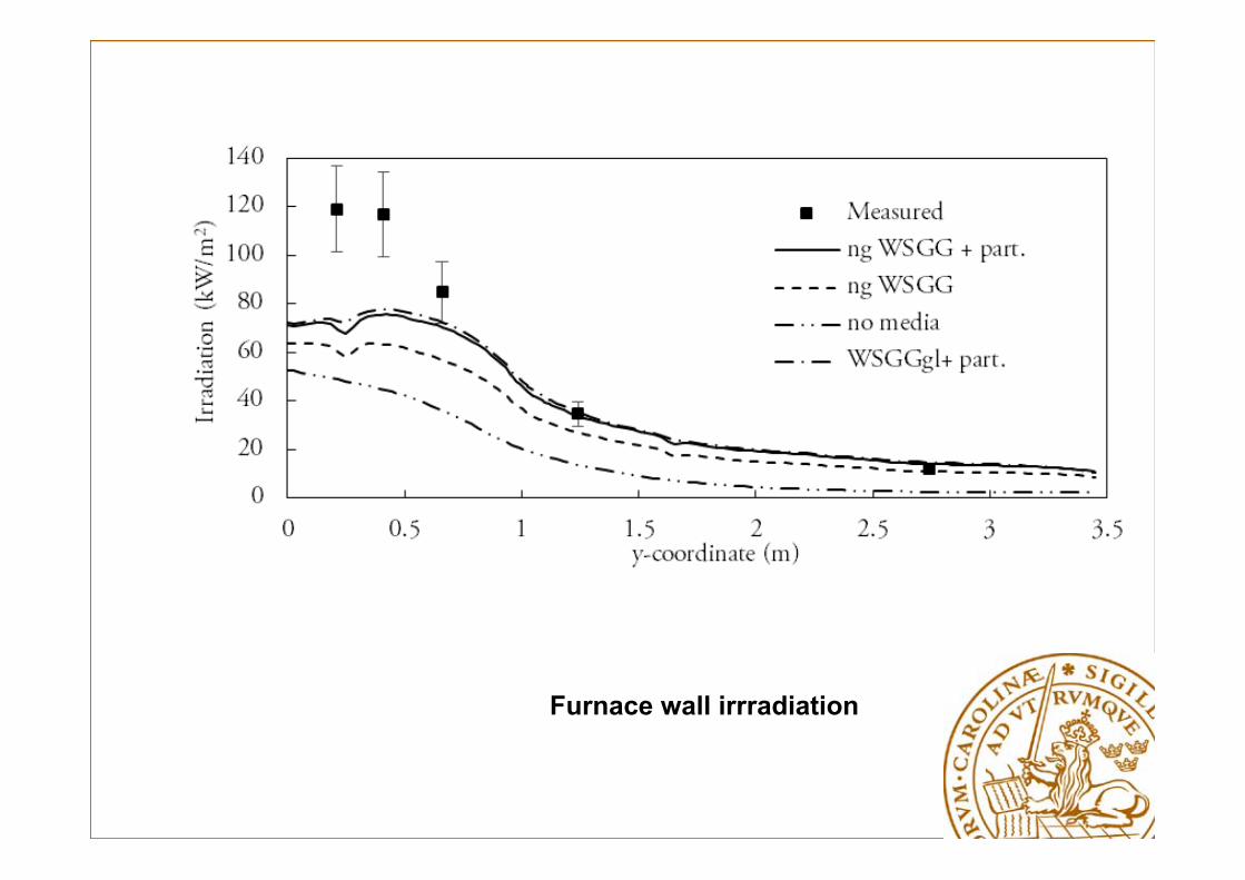
Furnace wall irrradiation