On mechanical modeling of composite materials
20
On mechanical modeling of composite materials Etienne Bonnaud Doctoral thesis no. 75, 2010 KTH Engineering Sciences Solid Mechanics Royal Institute of Technology SE-100 44 Stockholm, Sweden
Transcript of On mechanical modeling of composite materials
On mechanical modeling of composite materials
Etienne Bonnaud
Doctoral thesis no. 75, 2010
KTH Engineering Sciences Solid Mechanics
Royal Institute of Technology SE-100 44 Stockholm, Sweden
TRITA HFL-0494 ISSN 1654-1472 ISRN KTH/HFL/R-10/09-SE Akademisk avhandling som med tillstånd av Kungliga Tekniska Högskolan i Stockholm framlägges till offentlig granskning för avläggande av teknisk doktorsexamen fredagen den 1:a oktober kl. 10.15 i sal E3, Kungliga Tekniska Högskolan, Osquars Backe 14, Stockholm.
2
Preface The work presented in this thesis was carried out at the Department of Solid Mechanics, Royal
Institute of Technology (KTH), Stockholm, Sweden in four distinct occurrences stretching from
May 1997 to May 2010.
During the first part of this thesis, between May 1997 and September 2000, I was employed at
KTH as a full-time doctoral student; my supervisor, Assoc. Prof. Jonas Neumeister, is
acknowledged for initiating the first two research projects of this thesis and for guiding me
through problems related to elasticity and fiber failures in composite materials.
In January 2005, after working a few years in the industry, I initiated an industrial research project
between KTH and Infineon Technology Sweden AB. This project dealt with the mechanical
behavior of solder joints. At that time, I became an industrial doctoral student under the
supervision of Prof. Peter Gudmundson. My former Swedish and German Infineon managers
Håkan Sjödin and Heinz Pape, respectively, are gratefully acknowledged for actively supporting
and financing this project, which nonetheless abruptly ended in March 2006 when Infineon
Technology closed down its activity in Sweden and laid off all the employees.
In September 2006, after working a few months at Sony Ericsson Mobile Communication AB, I
initiated another industrial research project with KTH dealing with the mechanical behavior of
polymers. Again, I became an industrial doctoral student but this time under the supervision of
Assoc. Prof. Jonas Faleskog. This project appeared to be much more intricate than expected and I
am grateful for the many hours spent discussing the implementation of large strain plasticity in
Finite Element programs. The enthusiastic support of my former manager at Sony Ericsson, Leif
Brunström, was greatly appreciated but unfortunately could not prevent the project to suddenly
end when Sony Ericsson closed down its development activity in Stockholm and laid off all the
employees in February 2009.
As a result, I came back to KTH in March 2009 where I was offered a position as a full-time
doctoral student in order to complete the Sony Ericsson polymer project and to apply some of the
3

results to paper mechanics. Prof. Sören Östlund and Assoc. Prof. Mikael Nygårds are greatly
acknowledged for allowing this financial support through BiMaC Innovation.
I am also indebted to Assoc. Prof. Bengt Sundström and Prof. Mårten Olsson for the numerous
Solid Mechanics related questions I have asked them over the years and that they always answered
patiently and accurately. Finally I would like to thank Hans Öberg for help with experiments and
Bengt Möllerberg for specimen manufacturing.
Last but not least I want to thank my present and former colleagues at KTH, Infineon and Sony
Ericsson for all the nice moments we have shared during these thirteen years.
Stockholm, June 2010.
Etienne Bonnaud
4
List of appended papers
Paper A: Etienne Bonnaud and Jonas Neumeister, “Proper Boundary Conditions and Stress
Solutions for Infinitely Layered Media with General Orthotropic Layers,” Report 238, Department
of Solid Mechanics, Royal Institute of Technology, Stockholm. Subsequently published in a
shortened version: ”Proper Boundary Conditions for Infinitely Layered Orthotropic Media,” 2000,
Journal of Applied Mechanics, vol. 67, pp. 629-632.
Paper B: Jonas Neumeister and Etienne Bonnaud, “Dynamical Effects on the Burst Size
Distribution and Universality in Fiber Bundles,” Report 285, Department of Solid Mechanics,
Royal Institute of Technology, Stockholm.
Paper C: Etienne Bonnaud and Jonas Neumeister, “Inertia and Damping Effects on the Damage
Dependent Burst Size Distribution of Fiber Bundles,” 2001, Physics Letters A, vol. 290, pp. 261-
269.
Paper D: Etienne Bonnaud, “Issues on Viscoplastic Characterization of Lead-Free Solder for
Drop Test Simulations,” Report 487, Department of Solid Mechanics, Royal Institute of
Technology, Stockholm.
Paper E: Etienne Bonnaud and Jonas Faleskog, “Explicit, Fully Implicit and Forward Gradient
Numerical Integration of a Hyperelasto-Viscoplastic Constitutive Model for Amorphous Polymers
Undergoing Finite Deformation,” Report 492, Department of Solid Mechanics, Royal Institute of
Technology, Stockholm.
Paper F: Mikael Nygårds and Etienne Bonnaud, “Network Modeling of Paper Materials: a
Micromechanical Model to Investigate the Influence of Fiber Properties,” Report 493, Department
of Solid Mechanics, Royal Institute of Technology, Stockholm.
5

Introduction
1. Background
As the name implies, composite materials are made up of different constituents: in their simplest
form, a stiffer reinforcement surrounded by a softer matrix. Such combinations allow to achieve
overall properties which are at least the sum of the individual properties.
Natural composite materials have existed in numerous forms for a long time. Wood, for example,
consists of cellulose fibers (strong in tension) embedded in a lignin matrix (resisting compression).
Manufactured composite materials appear early in mankind history mainly for construction
purposes but have recently been the focus of intensive scientific research. As a result, industrial
composite materials are now extensively used in several applications such as vehicles, sport
equipments and microelectronics.
Usually, distinction is made between microcomposites, like alloys, where two different phases are
finely dispersed into one another and macrocomposites, like metal reinforced concrete beams,
made up of two distinct materials. In the following only macrocomposites will be considered.
A very large variety of composite materials can be designed depending, among others, on the
matrix material, the reinforcement material and the reinforcement shape. Over the years, three
main matrix material groups have emerged: polymer resins, metals and ceramics.
Among polymer resins, due to their relatively simple manufacturing processes, thermosetting
polymers are today predominantly used. For numerous every day applications, simpler and
cheaper resins (like polyester and epoxy resins) are sufficient, whereas for more specific
applications, where chemical resistance, higher temperature or fire resistance is a concern, more
advanced and more expensive resins (like vinylester, polyimids and phenolic resins) are necessary.
Nonetheless, and despite the necessity of high pressure and high temperature during injection,
thermoplastic polymers are becoming more and more popular for applications where toughness
matters: several sailing boat constructors have for example begun to manufacture hulls in
polypropylene.
Relatively light metal matrices are of interest for applications where high loadings need to be
sustained but for which, weight and toughness are a concern. Possible candidates are for example
6

aluminum and tin. By reinforcing metal matrices, increased yield, tensile, creep or fatigue
strengths can be achieved.
Finally, ceramic matrices (like for instance silicon carbide: SiC) are almost exclusively used in
high technology applications within the nuclear or space industry, where very high temperature
resistance is of interest; they are unfortunately relatively expensive to manufacture.
In order to provide a strengthening effect, reinforcement materials should obviously have a
relatively higher stiffness and strength than the matrix material. A new trend for low cost
composites is to use vegetal fibers (like linen, hemp or wood) which apart from being cheap are
also ecological and biodegradable; nonetheless for more technically advanced applications, glass,
aramid (Kevlar), carbon, metal and ceramic are still most widely used. The shape of reinforcement
can vary a lot and mainly depends on the sought mechanical properties: particles, short fibers
(whiskers) aligned or randomly dispersed, aligned long fibers or long fibers woven in a roving; see
Fig. 1 where different types of reinforcement are illustrated (reproduced from [1]).
a) b) c)
Figure 1: Schematic illustration of different reinforcements, a) particles, b) whiskers, c) long fibers.
To summarize, three main groups of materials (metals, ceramics and amorphous) are commonly
used to manufacture composites and can serve both as matrix material and as reinforcement
material, either in connection with another material from the same group (steel fibers in aluminum
7
matrix, glass fibers in polymer matrix) or with a material from another group (ceramic particles in
a metal matrix).
One of the main reasons behind the development of composites is the possibility to produce
materials combining low weight and high stiffness. As already mentioned, reinforcement materials
are stiffer than matrix materials but they also happen to have higher density. In order to achieve
high stiffness while keeping low weight, stiffness is only enhanced in the directions where it
matters. Assuming known in advance, both intensities and directions of the loads to be
experienced by the composite material allows, at the conception stage, to accordingly place the
right amount of reinforcement material in the right directions. This concept is precisely the ground
for a noteworthy group among long fiber reinforced composites: laminates in which plies or
laminae (where fibers are all aligned in the same direction) are glued together at angles determined
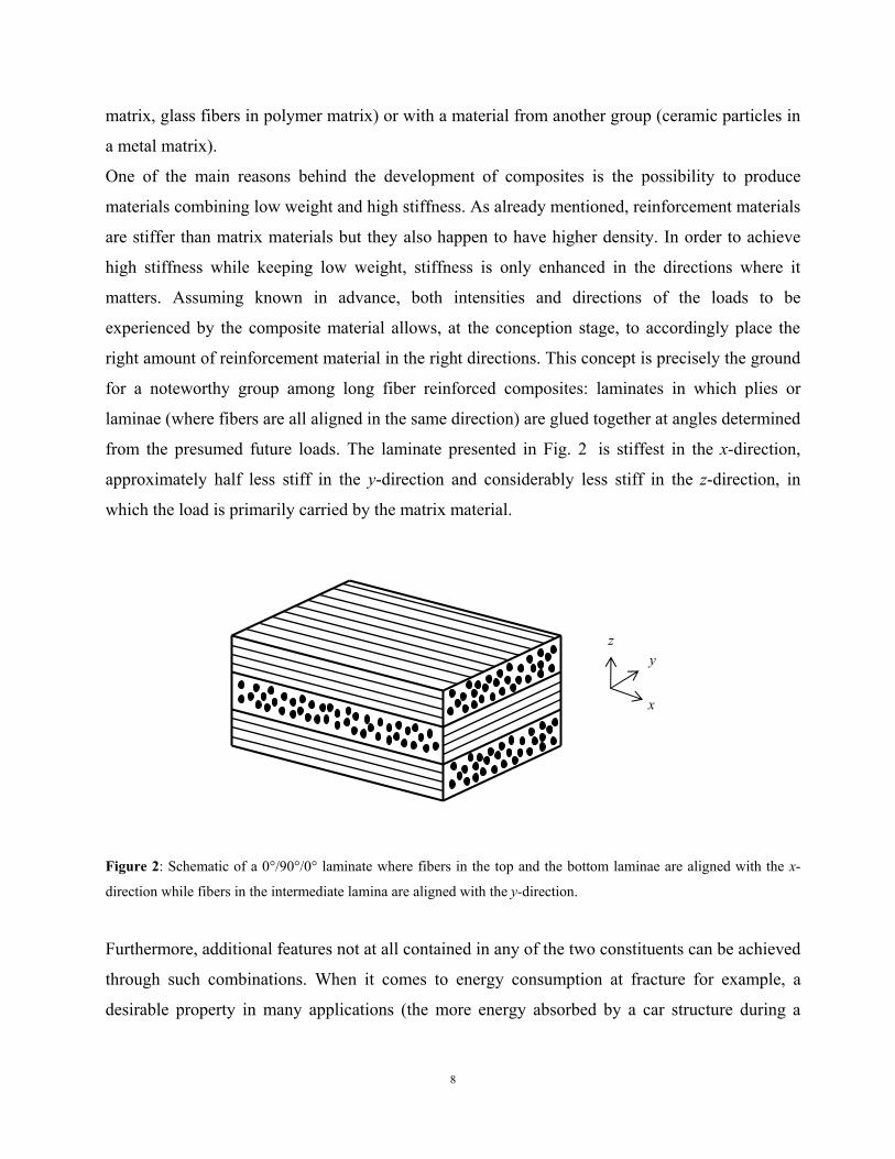
from the presumed future loads. The laminate presented in Fig. 2. is stiffest in the x-direction,
approximately half less stiff in the y-direction and considerably less stiff in the z-direction, in
which the load is primarily carried by the matrix material.
zy
x
Figure 2: Schematic of a 0°/90°/0° laminate where fibers in the top and the bottom laminae are aligned with the x-
direction while fibers in the intermediate lamina are aligned with the y-direction.
Furthermore, additional features not at all contained in any of the two constituents can be achieved
through such combinations. When it comes to energy consumption at fracture for example, a
desirable property in many applications (the more energy absorbed by a car structure during a
8

collision, the less violent its impact for the driver), energy is not only consumed by fibers and
matrix fracture but also by fiber debonding and delamination.
Averaged mechanical properties are often sufficient when evaluating strains and displacements at
the laminate level. However, stress responses require a more detailed level of refinement meaning
that properties need to be averaged at more internal levels. In a composite panel for example,
possible levels are: laminate, lamina, woven roving, bundle of fibers, individual fiber and resin
levels. Studying failure initiation in a laminate is a typical case when detailed stress fields are
essential. The main concern is to assess stresses in levels where failure is likely to occur and once
a constituent has broken to evaluate the consequences at other levels, e.g. the laminate level. The
study of the mechanics of composites therefore involves a two way analysis: global loading results
in local stresses and possible damage, which in turn affects the global behavior of the laminate.
However a fully comprehensive mechanical model for fiber composites would contain a huge
number of parameters, namely all pertinent properties of each constituent and all pertinent
properties of each interface between different levels. Studying composite structures must therefore
be restricted to certain aspects, for example applying a load at a given level and investigating the
response at the level immediately below. Again, the common approach is to study separately the
different phenomena involved by isolating certain components of a certain level. Eventually, such
studies will lead to a better understanding of the overall behavior.
9
2. Summary of the appended papers
The work presented in this thesis touches upon different aspects of the mechanical behavior of
composite materials. The first article presents a new method to calculate stresses and strains in a
laminate. The second and third articles deal with fiber failures. The fourth and fifth articles focus
on matrix behavior (metallic matrix and polymer matrix). Finally, the sixth article is an application
of the polymer matrix model to paper material.
Paper A
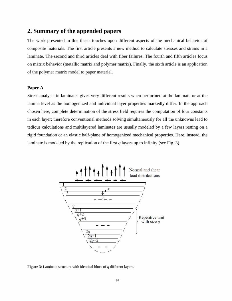
Stress analysis in laminates gives very different results when performed at the laminate or at the
lamina level as the homogenized and individual layer properties markedly differ. In the approach
chosen here, complete determination of the stress field requires the computation of four constants
in each layer; therefore conventional methods solving simultaneously for all the unknowns lead to
tedious calculations and multilayered laminates are usually modeled by a few layers resting on a
rigid foundation or an elastic half-plane of homogenized mechanical properties. Here, instead, the
laminate is modeled by the replication of the first q layers up to infinity (see Fig. 3).
Figure 3: Laminate structure with identical blocs of q different layers.
10
As there of course does not exist any laminate of infinite extent, this again is an approximation but
which appears to be better than the previously mentioned ones. Say that stresses are to be
calculated in a 100 layers composite. The layers of main interest are the ones close to the loaded
region where stresses are likely to be high. Usual methods would take into account the first two
layers and approximate or even disregard the influence of the 98 others. Here, the 100 layers are
all exactly modeled as layers and only the boundary conditions on the 100th differ from reality.
According to the Saint Venant’s principle, the further from the region of interest approximations
are made, the less they matter, which obviously makes an approximation on the 100th layer better
than an approximation on the second layer. Furthermore this method allows to reduce the number
of unknowns to four, namely the four coefficients characterizing the first layer onto which loads
are applied. Coefficients in other layers of interest can subsequently be determined by simple
matrix multiplication. Stress results from the multilayered model are presented and compared to
stresses from the homogeneous material [2].
Paper B and Paper C
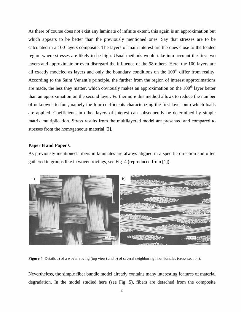
As previously mentioned, fibers in laminates are always aligned in a specific direction and often
gathered in groups like in woven rovings, see Fig. 4 (reproduced from [1]).
a) b)
Figure 4: Details a) of a woven roving (top view) and b) of several neighboring fiber bundles (cross section).
Nevertheless, the simple fiber bundle model already contains many interesting features of material
degradation. In the model studied here (see Fig. 5), fibers are detached from the composite
11

structure, clamped at both ends and submitted to the same increasing load. All intact fibers are
furthermore assumed to carry an equal load throughout the degradation process (true global load
sharing assumption).
Figure 5: Fiber bundle model with mass attached and viscous damper . Applied displacement and measured force
are noted and , respectively.
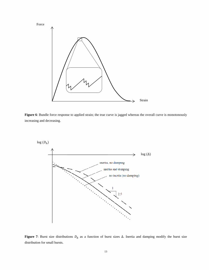
Noticeable is that fibers usually break in small groups called bursts: the force lost in a newly
broken fiber overloads the remaining ones and possibly causes the rupture of further weak fibers
(see Fig. 6). Burst occurrences during the failure process obviously depend on the fibers
themselves through their statistical strength distribution. What however does not depend on the
fiber strength distribution is the mutual relation between bursts of different sizes Δ summed up
over the entire failure process . The burst size distribution is therefore said to be universal as its
shape is independent of the fiber properties. Moreover, in an assumed massless bundle, this
distribution follows a power law that gives a straight line in a log-log diagram, see [3] for details.
Here, in an attempt to improve modeling of damage progression, additional effects as inertia and
damping are taken into account. Their consequences on burst size distributions are investigated:
distributions are shown to remain universal but with notably altered shapes for small burst sizes
(see Fig. 7).
Inertia increases the number of large bursts to the detriment of small ones; combined inertia and
damping are shown to render an intermediary case between the ones with and without inertia.
Nevertheless, all distributions approach a straight line of same slope for larger burst sizes.
12
Force
Strain
Figure 6: Bundle force response to applied strain; the true curve is jagged whereas the overall curve is monotonously
increasing and decreasing.
Figure 7: Burst size distributions as a function of burst sizes Δ. Inertia and damping modify the burst size
distribution for small bursts.
log
log Δ
13
Paper D
In order to characterize the global mechanical behavior of composites, knowledge of the
mechanical behavior of the matrix is essential: as being the interface with the surroundings, the
matrix material is naturally the first to experience loads or impacts.
The first step in experimentally characterizing materials and particularly metals is usually to
conduct a tensile test. As simple as it is, this test gives important information about the elastic and
the plastic behavior. For metals featuring little viscosity, the transition between the elastic and the
plastic regimes is easy to establish. The constant slope of the elastic part of the curve gives the
elasticity modulus and the not necessary constant slope of the plastic part of the curve gives the
elasto-plastic modulus; this modulus is generally associated to hardening (isotropic and/or
kinematic). When viscosity effects are not negligible (as for soft metals or metals relatively close
to their fusion temperature) it is difficult to establish a clear elastic-plastic transition and more
advanced numerical methods to estimate material parameters are necessary. Furthermore, in that
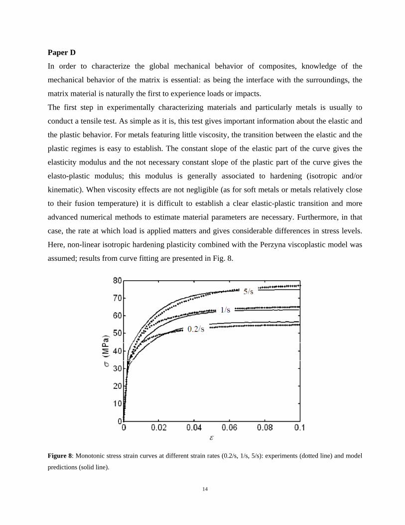
case, the rate at which load is applied matters and gives considerable differences in stress levels.
Here, non-linear isotropic hardening plasticity combined with the Perzyna viscoplastic model was
assumed; results from curve fitting are presented in Fig. 8.
Figure 8: Monotonic stress strain curves at different strain rates (0.2/s, 1/s, 5/s): experiments (dotted line) and model
predictions (solid line).
14
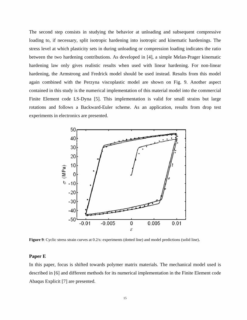
The second step consists in studying the behavior at unloading and subsequent compressive
loading to, if necessary, split isotropic hardening into isotropic and kinematic hardenings. The
stress level at which plasticity sets in during unloading or compression loading indicates the ratio
between the two hardening contributions. As developed in [4], a simple Melan-Prager kinematic
hardening law only gives realistic results when used with linear hardening. For non-linear
hardening, the Armstrong and Fredrick model should be used instead. Results from this model
again combined with the Perzyna viscoplastic model are shown on Fig. 9. Another aspect
contained in this study is the numerical implementation of this material model into the commercial
Finite Element code LS-Dyna [5]. This implementation is valid for small strains but large
rotations and follows a Backward-Euler scheme. As an application, results from drop test
experiments in electronics are presented.
Figure 9: Cyclic stress strain curves at 0.2/s: experiments (dotted line) and model predictions (solid line).
Paper E
In this paper, focus is shifted towards polymer matrix materials. The mechanical model used is
described in [6] and different methods for its numerical implementation in the Finite Element code
Abaqus Explicit [7] are presented.
15
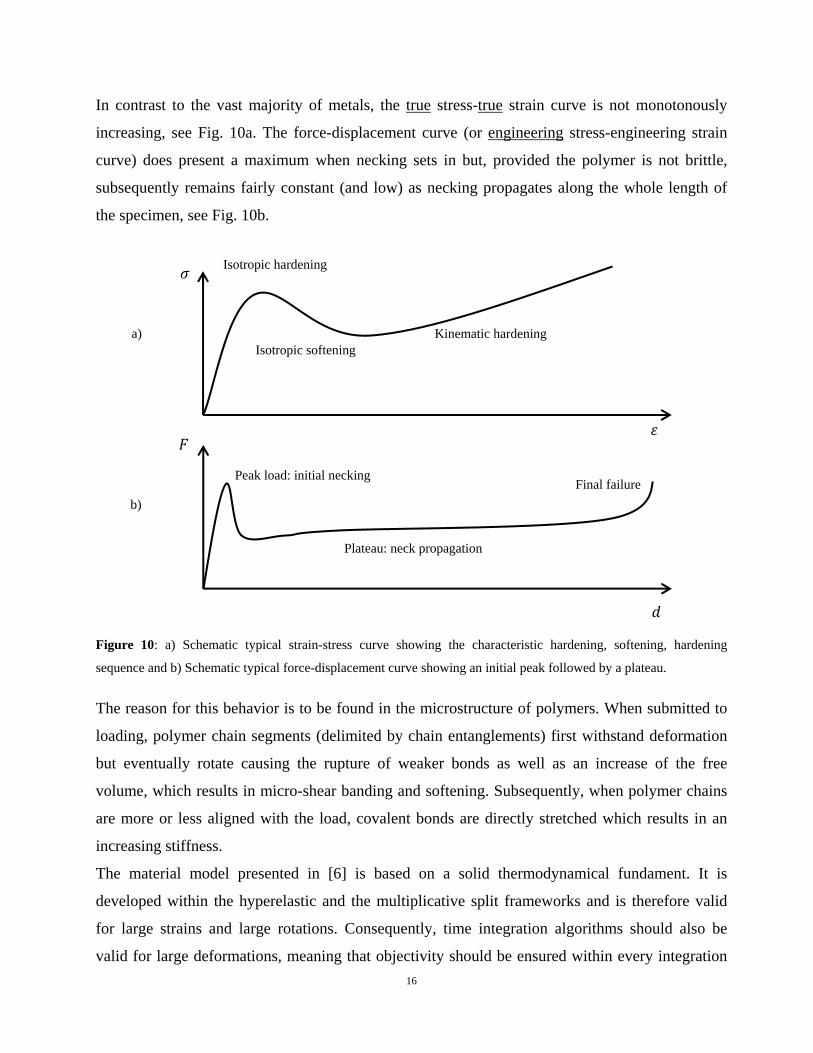
In contrast to the vast majority of metals, the true stress-true strain curve is not monotonously
increasing, see Fig. 10a. The force-displacement curve (or engineering stress-engineering strain
curve) does present a maximum when necking sets in but, provided the polymer is not brittle,
subsequently remains fairly constant (and low) as necking propagates along the whole length of
the specimen, see Fig. 10b.
Figure 10: a) Schematic typical strain-stress curve showing the characteristic hardening, softening, hardening
sequence and b) Schematic typical force-displacement curve showing an initial peak followed by a plateau.
Isotropic hardening
Isotropic softening Kinematic hardening
Peak load: initial necking
Plateau: neck propagation
Final failure
a)
b)
The reason for this behavior is to be found in the microstructure of polymers. When submitted to
loading, polymer chain segments (delimited by chain entanglements) first withstand deformation
but eventually rotate causing the rupture of weaker bonds as well as an increase of the free
volume, which results in micro-shear banding and softening. Subsequently, when polymer chains
are more or less aligned with the load, covalent bonds are directly stretched which results in an
increasing stiffness.
The material model presented in [6] is based on a solid thermodynamical fundament. It is
developed within the hyperelastic and the multiplicative split frameworks and is therefore valid
for large strains and large rotations. Consequently, time integration algorithms should also be
valid for large deformations, meaning that objectivity should be ensured within every integration 16
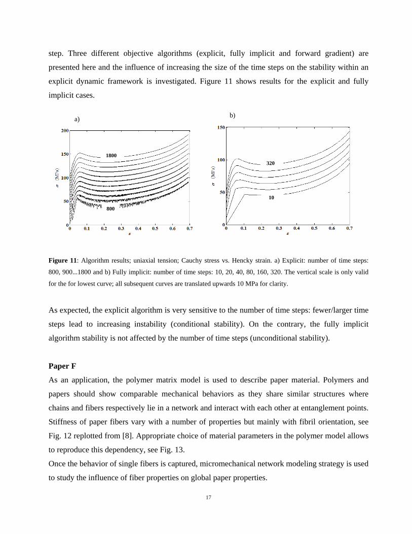
step. Three different objective algorithms (explicit, fully implicit and forward gradient) are
presented here and the influence of increasing the size of the time steps on the stability within an
explicit dynamic framework is investigated. Figure 11 shows results for the explicit and fully
implicit cases.
b) a)
1800 320
10
800
Figure 11: Algorithm results; uniaxial tension; Cauchy stress vs. Hencky strain. a) Explicit: number of time steps:
800, 900...1800 and b) Fully implicit: number of time steps: 10, 20, 40, 80, 160, 320. The vertical scale is only valid
for the for lowest curve; all subsequent curves are translated upwards 10 MPa for clarity.
As expected, the explicit algorithm is very sensitive to the number of time steps: fewer/larger time
steps lead to increasing instability (conditional stability). On the contrary, the fully implicit
algorithm stability is not affected by the number of time steps (unconditional stability).
Paper F
As an application, the polymer matrix model is used to describe paper material. Polymers and
papers should show comparable mechanical behaviors as they share similar structures where
chains and fibers respectively lie in a network and interact with each other at entanglement points.
Stiffness of paper fibers vary with a number of properties but mainly with fibril orientation, see
Fig. 12 replotted from [8]. Appropriate choice of material parameters in the polymer model allows
to reproduce this dependency, see Fig. 13.
Once the behavior of single fibers is captured, micromechanical network modeling strategy is used
to study the influence of fiber properties on global paper properties.
17

Figure 12: Experimental uniaxial tension test of single fibers with different fibril angles.
Figure 13: Computed uniaxial tension test of single fibers with different fibril angles.
18

3. Conclusions
A complete model for composite materials would involve so many different aspects and
phenomena that it would be very difficult to handle. Consequently, analyses are restricted to
investigations of certain behaviors at particular levels.
The influence of elastic properties of (infinitely) many layers on detailed stresses is investigated
analytically and the method is shown to reduce to the computation of only four coefficients.
Statistical analysis of fiber bundles results in very predictable behaviors, which can be described
with only two parameters. The behavior of matrix material is modeled analytically and
implemented in Finite Element codes for numerical simulations. Here, the number of parameters
is only an experimental concern and barely affects the computational running time; high number
of material parameters is therefore generally preferred as it leads to increased accuracy.
Hopefully, such findings will facilitate forthcoming efforts to improve material description of
composite materials.
References [1] Hull, D., Clyne, T.W., 1981, An Introduction to Composite Materials, Cambridge Solid State
Science Series.
[2] Bjarnehed, H.L., 1991, “Rigid Punch on Stressed Orthotropic Half-Plane with Partial Slip,”
Journal of Applied Mechanics, vol. 58, no. 1, pp. 128-133.
[3] Hemmer, P.C., Hansen, A., 1992, “The Distribution of Simultaneous Fiber Failures in Fiber
Bundles,” Journal of Applied Mechanics, vol. 59, pp. 909-914.
[4] Ottosen, N.S., Ristinmaa, M., 2005, The Mechanics of Constitutive Modelling, Elsevier,
Oxford.
[5] LS-Dyna Keyword User's Manual, Livermore Software Technology Corporation, Version 970,
2003.
19
20
[6] Anand, L., Gurtin, M.E., 2003, “A Theory of Amorphous Solids Undergoing Large
Deformations, with Application to Polymeric Glasses,” International Journal of Solids and
Structures, vol. 40, pp. 1465-1487.
[7] Abaqus, 2009, Abaqus Manuals, Simulia, 6.9 edition.
[8] Page, D., El-Hosseiny, F., 1983, “Mechanical Properties of Single Wood Pulp Fibers. Part VI.
Fibril Angle and the Shape of the Stress-Strain Curve,” Journal of Pulp and Paper Science, vol. 9,
pp. 99-100.