On Localized Vapor Pressure Gradients Governing ... · On Localized Vapor Pressure Gradients...
16
On Localized Vapor Pressure Gradients Governing Condensation and Frost Phenomena Saurabh Nath and Jonathan B. Boreyko* Department of Biomedical Engineering and Mechanics, Virginia Tech, Blacksburg, Virginia 24061, United States * S Supporting Information ABSTRACT: Interdroplet vapor pressure gradients are the driving mechanism for several phase-change phenomena such as con- densation dry zones, interdroplet ice bridging, dry zones around ice, and frost halos. Despite the fundamental nature of the underlying pressure gradients, the majority of studies on these emerging phenomena have been primarily empirical. Using classical nucleation theory and Becker−Dö ring embryo formation kinetics, here we calculate the pressure field for all possible modes of condensation and desublimation in order to gain fundamental insight into how pressure gradients govern the behavior of dry zones, condensation frosting, and frost halos. Our findings reveal that in a variety of phase-change systems the thermodynamically favorable mode of nucleation can switch between condensation and desublimation depending upon the temperature and wettability of the surface. The calculated pressure field is used to model the length of a dry zone around liquid or ice droplets over a broad parameter space. The long-standing question of whether the vapor pressure at the interface of growing frost is saturated or supersaturated is resolved by considering the kinetics of interdroplet ice bridging. Finally, on the basis of theoretical calculations, we propose that there exists a new mode of frost halo that is yet to be experimentally observed; a bimodal phase map is developed, demonstrating its dependence on the temperature and wettability of the underlying substrate. We hope that the model and predictions contained herein will assist future efforts to exploit localized vapor pressure gradients for the design of spatially controlled or antifrosting phase-change systems. ■ INTRODUCTION Anyone who has put a lid on a coffee cup and looked at the droplets condensing underneath has observed an annular dry zone around each droplet where no new droplets appear. One possible mechanism for these apparent dry zones surrounding condensing droplets is the cooperative diffusion governing dropwise condensation, in which the out-of-plane diffusion of vapor toward the substrate is coupled with an in-plane exchange of vapor between droplets. 1 The in-plane pressure gradients are due to the diversity of droplet sizes on the condensing surface, as nanometric droplets exhibit highly supersaturated vapor pressures resulting from their curvature whereas micrometric droplets are approximately saturated. Therefore, when smaller droplets are proximal to a larger droplet, the in-plane pressure gradient driving the evaporation of these smaller droplets can dominate the out-of-plane differential driving their growth, creating a dry zone around the large droplet. 2 Another mechanism for dry zones is that nucleation itself can be suppressed around pre-existing droplets because the critical vapor pressure to form an embryo is larger than the (nearly saturated) equilibrium pressure over large droplets. 3,4 While the case of all-liquid droplets requires disparities in droplet size to produce interdroplet pressure gradients, an ice droplet exhibits a lower pressure than a supercooled liquid droplet even when both droplets are the same size. This inherent pressure differential between frozen droplets and liquid droplets is because ice has a lower saturation vapor pressure than supercooled water at the same temperature. 5 Ice is therefore a humidity sink for both nanometric (super- saturated) liquid droplets and larger (saturated) liquid droplets. As an ice droplet siphons water vapor from neighboring liquid droplets, this harvest of water molecules manifests itself as ice bridges growing from the frozen droplet toward the evaporating liquid droplets. 6−8 The liquid droplets being harvested will freeze as soon as the ice bridges connect; these newly frozen droplets will in turn grow ice bridges to the next row of supercooled condensate, thus propagating frost across the surface. Interdroplet ice bridging is now thought to be the dominant mechanism for condensation frosting on hydro- phobic 7−9 and superhydrophobic 7,10−14 surfaces chilled be- neath the dew point because only a single droplet needs to freeze due to heterogeneous nucleation for the chain reaction of ice bridges to occur. Very recently, we showed that a stable dry zone can exist around a frozen droplet when the nucleation sites for supercooled condensation are sufficiently sparse and/or the Received: April 18, 2016 Revised: June 27, 2016 Published: July 27, 2016 Article pubs.acs.org/Langmuir © 2016 American Chemical Society 8350 DOI: 10.1021/acs.langmuir.6b01488 Langmuir 2016, 32, 8350−8365
Transcript of On Localized Vapor Pressure Gradients Governing ... · On Localized Vapor Pressure Gradients...

On Localized Vapor Pressure Gradients Governing Condensation andFrost PhenomenaSaurabh Nath and Jonathan B. Boreyko*
Department of Biomedical Engineering and Mechanics, Virginia Tech, Blacksburg, Virginia 24061, United States
*S Supporting Information
ABSTRACT: Interdroplet vapor pressure gradients are the drivingmechanism for several phase-change phenomena such as con-densation dry zones, interdroplet ice bridging, dry zones around ice,and frost halos. Despite the fundamental nature of the underlyingpressure gradients, the majority of studies on these emergingphenomena have been primarily empirical. Using classicalnucleation theory and Becker−Doring embryo formation kinetics,here we calculate the pressure field for all possible modes ofcondensation and desublimation in order to gain fundamentalinsight into how pressure gradients govern the behavior of dryzones, condensation frosting, and frost halos. Our findings revealthat in a variety of phase-change systems the thermodynamicallyfavorable mode of nucleation can switch between condensation anddesublimation depending upon the temperature and wettability of the surface. The calculated pressure field is used to model thelength of a dry zone around liquid or ice droplets over a broad parameter space. The long-standing question of whether the vaporpressure at the interface of growing frost is saturated or supersaturated is resolved by considering the kinetics of interdroplet icebridging. Finally, on the basis of theoretical calculations, we propose that there exists a new mode of frost halo that is yet to beexperimentally observed; a bimodal phase map is developed, demonstrating its dependence on the temperature and wettability ofthe underlying substrate. We hope that the model and predictions contained herein will assist future efforts to exploit localizedvapor pressure gradients for the design of spatially controlled or antifrosting phase-change systems.
■ INTRODUCTION
Anyone who has put a lid on a coffee cup and looked at thedroplets condensing underneath has observed an annular dryzone around each droplet where no new droplets appear. Onepossible mechanism for these apparent dry zones surroundingcondensing droplets is the cooperative diffusion governingdropwise condensation, in which the out-of-plane diffusion ofvapor toward the substrate is coupled with an in-plane exchangeof vapor between droplets.1 The in-plane pressure gradients aredue to the diversity of droplet sizes on the condensing surface,as nanometric droplets exhibit highly supersaturated vaporpressures resulting from their curvature whereas micrometricdroplets are approximately saturated. Therefore, when smallerdroplets are proximal to a larger droplet, the in-plane pressuregradient driving the evaporation of these smaller droplets candominate the out-of-plane differential driving their growth,creating a dry zone around the large droplet.2 Anothermechanism for dry zones is that nucleation itself can besuppressed around pre-existing droplets because the criticalvapor pressure to form an embryo is larger than the (nearlysaturated) equilibrium pressure over large droplets.3,4
While the case of all-liquid droplets requires disparities indroplet size to produce interdroplet pressure gradients, an icedroplet exhibits a lower pressure than a supercooled liquiddroplet even when both droplets are the same size. This
inherent pressure differential between frozen droplets andliquid droplets is because ice has a lower saturation vaporpressure than supercooled water at the same temperature.5 Iceis therefore a humidity sink for both nanometric (super-saturated) liquid droplets and larger (saturated) liquid droplets.As an ice droplet siphons water vapor from neighboring liquiddroplets, this harvest of water molecules manifests itself as icebridges growing from the frozen droplet toward the evaporatingliquid droplets.6−8 The liquid droplets being harvested willfreeze as soon as the ice bridges connect; these newly frozendroplets will in turn grow ice bridges to the next row ofsupercooled condensate, thus propagating frost across thesurface. Interdroplet ice bridging is now thought to be thedominant mechanism for condensation frosting on hydro-phobic7−9 and superhydrophobic7,10−14 surfaces chilled be-neath the dew point because only a single droplet needs tofreeze due to heterogeneous nucleation for the chain reaction ofice bridges to occur.Very recently, we showed that a stable dry zone can exist
around a frozen droplet when the nucleation sites forsupercooled condensation are sufficiently sparse and/or the
Received: April 18, 2016Revised: June 27, 2016Published: July 27, 2016
Article
pubs.acs.org/Langmuir
© 2016 American Chemical Society 8350 DOI: 10.1021/acs.langmuir.6b01488Langmuir 2016, 32, 8350−8365

freezing event occurs during the early growth of thecondensate.2 Under these conditions, the droplets are smalland sparse such that the liquid droplets being harvested by afrozen droplet will completely evaporate before the ice bridgescan connect.2 Therefore, it is evident that the pressure gradientbetween ice and water can be used for the dual purposes ofspreading frost and creating dry zones, depending upon theconditions of the system. In addition to using ice, it is alsopossible to create dry zones around humidity sinks by utilizinghygroscopic liquids such as salty water,15−17 nectar,18 andglycols19 in conjunction with the growth of condensation and/or frost. However, in these cases the depression in vaporpressure of the hygroscopic droplet(s) with respect tocondensation/frost decays to zero as the hygroscopic dropletsbecome increasingly diluted with the harvested water vapor.Though the saturation vapor pressure of ice is always lower
than water under isothermal conditions, interestingly thispressure gradient can flip when considering the initial freezingof a supercooled liquid droplet. During the first stage offreezing, known as recalescence, the rapid (∼10 ms) formationof an ice-crystal scaffold causes the droplet to quickly heat up toapproximately 0 °C as a result of the sudden input of latentheat.20 Until this latent heat is dumped into the ambientatmosphere via evaporation and into the substrate byconduction, the freezing droplet is warmer than its supercooledliquid neighbors. This can be sufficient to elevate its vaporpressure above that of the water droplets. Indeed, the pressureincrease induced by recalescence can cause vapor to emanatefrom the frozen droplet such that satellite droplets nucleate onthe substrate around the droplet, which subsequently freezeover via interdroplet ice bridging to form what is known as afrost halo.20,21
It should now be clear that localized, interdroplet vaporpressure gradients are responsible for a variety of emergingphase-change phenomena such as dry zones, condensationfrosting, and frost halos. However, to date most reports onthese topics have been primarily experimental, and muchremains to be understood regarding the thermodynamics of thepressure gradients driving these phenomena. For example, tomodel the pressure difference between nucleating droplets andpre-existing droplets, one must calculate the critical vaporpressure required for embryo nucleation. Yet reports that havequantified the supersaturation required for nucleating liquid orice embryos have produced contradictory results that do notagree with each other (Supporting Information Figures S1 andS2).22−25 To complicate matters even further, these previousstudies estimating nucleation pressures used single values forthe kinetic constant of nucleation (I0 ∼ 1029 m−2s−1) and thecritical embryo formation rate for nucleation to occur (Ic ∼ 104
m−2s−1),26,27 despite their exact values being uncertain with I0/Ic spanning at least 3 orders of magnitude.22,28 To additionallyestimate the supersaturation required to grow an embryo onpre-existing ice (i.e., frost growth), the study by Na and Webb25
applied the same value of I0/Ic ∼ 1025 used for nucleation on adry surface, but this assumption that the ratio is the same for anice substrate is highly questionable. Indeed, there is a sharpdisagreement in the literature regarding whether the vaporpressure required for frost growth is to be consideredsaturated23,29−33 or supersaturated.25,34−36 Considering thatthe emerging phenomena discussed above are typically drivenby highly sensitive in-plane pressure gradients (i.e., extremelysmall relative to the out-of-plane pressure gradients), animproved understanding of the pressure field around nucleating
and pre-existing water and ice droplets on the substrate isrequired to accurately model these systems.Here, we utilize a synergistic blend of classical nucleation
theory, quasi-steady diffusive growth models, and experimentalresults to develop a comprehensive model of the contrastingvapor pressures around nucleating and pre-existing water/icedroplets and how they govern various condensation and frostphenomena. First, we calculate the critical pressure for embryoformation on a dry substrate as a function of temperature,surface wettability, and embryo formation rate. In contrast toNa and Webb’s assertion that condensation is alwaysthermodynamically favorable compared to desublimation,25
here we show that the preferred mode of embryo nucleationcan switch between condensation and desublimation, depend-ing upon the temperature and wettability of the surface. Byvarying the value of the I0/Ic ratio by 3 orders of magnitude forall calculations, it is concluded that the uncertainty in this ratiocan appreciably affect the nucleation pressures for some of theparameter space. Using recent measurements of the kinetics ofinterdroplet ice bridging7 in conjunction with the binodalcurves of saturated water and ice,5 we demonstrate that thevapor pressure at the interface of growing frost must be(approximately) saturated, in contrast to recent models positingsupersaturation. We then contextualize our model to emergingphase-change phenomena to show how the calculated pressurefield can be used to predict and control the behavior of dryzones, interdroplet frost growth, and frost halos. It is our hopethat this theoretical framework can guide the design andanalysis of future experiments seeking to control the growth ofcondensation and frost on surfaces.
■ MODEL FORMULATION
Saturation Vapor Pressure. The primary mechanism forlocal vapor pressure gradients in a vapor−water−ice system isthe difference in the saturation vapor pressures of water versusice. The Clausius−Clapeyron equation shows how thesaturation pressure (ps) between two phases i and j relates tothe absolute temperature (T) and the change in specificenthalpy associated with phase-change (hij(T)). This is given by
=p
T
h T
RT
d ln
d
( )s ij2 (1)
where R is the universal gas constant. This relation can beintegrated to obtain the saturated vapor pressures of water orice at different temperatures using the vapor pressure at thetriple point (pt = 611.657 ± 0.01 Pa, Tt = 273.16 K) as aboundary condition.37 Also, the latent heat in eq 1 needs to betaken as a function of temperature. In a seminal review paper,Murphy and Koop discuss how the variation of molar heatcapacity with temperature affects the latent heat at subzerotemperatures and in turn the saturation pressures.5 Incorporat-ing these variations of hij with temperature, we have plotted thesaturation pressure of vapor over water or ice in Figure 1. Thesaturation vapor pressure over ice is lower than that over waterfor all temperatures below 0 °C. By itself, this is sufficient tocreate a vapor pressure gradient in a vapor−water−ice systemthat can cause vapor to flow preferentially from water towardice. There are, however, other factors that can significantlyinfluence the pressure differential and in some cases evenreverse its direction altogether, which we discuss in thefollowing sections.
Langmuir Article
DOI: 10.1021/acs.langmuir.6b01488Langmuir 2016, 32, 8350−8365
8351

Supersaturation: Nucleation on a Dry Substrate. Thesaturation pressure of vapor over water or ice at a giventemperature, by definition, is the pressure at which the water/vapor or ice/vapor phases have the same chemical potential andare therefore in thermodynamic equilibrium. However, forphase-change processes such as condensation and desublima-tion to occur, they often require vapor pressures that exceed thesaturation pressure, known as supersaturation. The super-saturation of water vapor is thermodynamically metastable upto a certain limit because condensation and desublimation bothinvolve nucleation, that is, the creation of new interfaces thatare energetically costly.28,34 The amount of free enthalpyrequired for nucleation is dependent on whether the nucleationevent is homogeneous or heterogeneous. Homogeneousnucleation has been addressed in considerable depth in thefields of cloud physics and atmospheric sciences.38,39 For thisreason and also because the phenomena of dry zones, icebridging, and frost halos are generally intrinsic to substrates, welimit ourselves here to the case of heterogeneous nucleation.Note that in the present discussion we have not considered thenoncontinuum transport effects that have been studied inprevious works,40−42 which if considered would not change theformulation but use a different value of surface tension. We willfirst consider the case of new water/ice embryos nucleating ona dry portion of the substrate.Consider an embryo of radius of curvature r that nucleates
upon a substrate exhibiting a wall temperature Tw (Figure 2a)such that the saturation vapor pressure corresponding to thewall temperature would be ps,w. Recall from Figure 1 that thissaturation pressure will be slightly larger for liquid embryos(psl,w) versus ice embryos (psi,w). Because we are restrictingourselves to the cases of condensation or desublimation, it is anecessary but not sufficient condition that the surface isbeneath the dew point (p∞ > psl,w, for condensation) or beneath
the frost point (p∞ > psi,w, for desublimation) for nucleation tooccur, where p∞ is the partial pressure of water vapor in theambient atmosphere. The size of nucleating embryos is typicallyof order r ∼ 1 nm28 such that conductive losses are negligible,and it can be assumed that Td ≈ Tw, where Td is thetemperature inside the droplet near its liquid−vapor interface.Figure 2b shows the p−T diagram corresponding to the
nucleation process. When the temperature of the substrate is
fixed at Tw, the vapor pressure at the wall can increase along thedT = 0 path until nucleation occurs at a supersaturated vaporpressure: pn,w > ps,w (vertical arrows in Figure 2b). The criticalsupersaturation required for embryo formation can therefore beformulated as
=−p p
pSSD n w s w
s w
, ,
, (2)
where SSD is the abbreviation for the supersaturation degreeand SSD > 0 indicates supersaturation. To avoid confusion interminology, note that SSD describes the metastable super-saturation of water vapor that occurs locally at the surface toovercome the nucleation energy barrier.23,25 This is funda-mentally different from another commonly used supersatura-tion ratio, S = p∞/ps,w, that quantifies the diffusive growth rateand nucleation density of condensation/frost on a given surfacebut cannot comment on nucleation energy barriers.43−45
Therefore, SSD, rather than S, is the proper context fordiscussing supersaturation in the present work. The specificGibbs free energy change associated with the nucleation of thesupersaturated water vapor molecules can be written as34
Δ = −gRT
v
p
plnw n w
s w
,
, (3)
where v is the molar volume of water (for condensation) or ice(for desublimation).Instead of increasing the vapor pressure at a fixed wall
temperature, an alternate path to nucleation is cooling the wallwhile holding the vapor pressure constant at pw, with Ts,w beingthe saturation temperature corresponding to pw. For an initiallydry surface, the wall temperature can be decreased beneath Ts,walong the dP = 0 path until nucleation occurs at the criticaltemperature Tn,w < Ts,w (horizontal arrows in Figure 2b). ΔT =
Figure 1. Saturation pressure of vapor with respect to supercooledwater (blue line, right y axis) or ice (black line, right y axis) as afunction of temperature. Note that the difference in vapor pressurebetween saturated water and ice (red line, left y axis) peaks atapproximately Δp ≈ 27 Pa at −12 °C, as denoted by the dotted lines.Analytical expressions for these curves are available in the SupportingInformation (eqs S1− S4).
Figure 2. (a) Schematic of an embryo nucleating on a substrate bycondensation or desublimation at a supersaturated vapor pressure(pn,w). (b) p−T diagram showing the extent of supersaturation (orsubcooling) required to nucleate an embryo of water or ice.
Langmuir Article
DOI: 10.1021/acs.langmuir.6b01488Langmuir 2016, 32, 8350−8365
8352

Tn,w − Ts,w may therefore be looked upon as the degree ofsubcooling required for nucleation. Combining eqs 1 and 3, wecan relate the change in specific Gibbs free energy uponnucleation to the degree of subcooling as
Δ =Δ
gh
vT
Tij
n w, (4)
Of course, the critical p−T curve at which nucleation firstoccurs is path-independent: pn,w(Tw) ≡ Tn,w(pw).Now that the specific free enthalpy change upon nucleation
is known as a function of pn,w and Tw (eq 3), it is possible toestimate pn,w as an analytical expression in Tw provided that thevalue of Δg could be independently solved using an additionalrelation. Such an expression can be obtained by equating thechange in specific Gibbs energy (Δg) to the total Gibbs energy(ΔG). For an embryo of volume V, ΔG can be expressed as asummation of the negative change in energy inherent tosupersaturated vapor becoming liquid (or ice) and the positiveenergy barrier associated with the creation of the interfaces(liquid−solid and liquid−vapor interfaces for condensation andice−solid and ice−vapor for desublimation)34
σ σ σΔ = Δ + + −G V g A A ( )ij ij jk jk ik (5)
where i, j, and k are the three different phases (vapor, water orice, and the solid substrate) and Aij and σij represent the
interfacial area and surface tension between phases i and j.Assuming that the nucleating embryo exhibits a uniformspherical-cap shape, the critical radius of curvature wherenucleation is stable can by found by solving for ∂ΔG/∂r = 0:
σ* = −
Δ r
g
2 ij
(6)
Young’s relation can be used to collapse the three surfacetension terms down to a single dimensionless variable,46 oftendenoted as m
θσ σ
σ= =
−m cos jk ik
ij (7)
where θ is the intrinsic contact angle of the water (or ice) withthe smooth substrate. A point rarely mentioned in thenucleation literature is the chemical limit of hydrophobicityon smooth surfaces of around θmax ≈ 120°.47 Though ourcalculations assume a smooth substrate, they should generallyapply even for rough surfaces because the length scale ofsurface roughness tends to be larger than the size of nucleatingembryos (r ∼ 1−10 nm). Therefore, we restrict our parameterspace here to 0° ≤ θ ≤ 120°.By combining eqs 5−7, we obtain the critical change in free
energy required for nucleating an embryo:
Figure 3. Supersaturation degree (SSD) required for (a) condensation or (b) desublimation embryos to nucleate on a substrate as a function ofsurface temperature (Tw) for different surface wettabilities (θ = 30, 60, 90, and 120°) and embryo formation rates (I* = 1024 and 1027). All curveswere obtained by solving for eq 2 in conjunction with eq 10. The gray region depicting the SSD corresponding to θ = 30° is not visible because of itsextremely low variation with I*. (c) and (d) represent the SSD required for condensation and desublimation, respectively, as a function of wettability(θ) for different surface temperatures (Tw = 0, −10, −20, and −30 °C) and embryo formation rates (I* = 1024 and 1027). Although qualitativelysimilar, note that the SSD for desublimation is roughly 3 times greater than the corresponding condensation SSD requirement over the entireparameter space.
Langmuir Article
DOI: 10.1021/acs.langmuir.6b01488Langmuir 2016, 32, 8350−8365
8353

π σΔ * =
Δ + −G
gm m
43
(2 )(1 )ij3
22
(8)
Using the Becker−Doring exponential relationship of theembryo formation kinetics,27 we can solve for ΔG*independently of eq 8 as a function of the surface temperatureand embryo formation rate
= − Δ⎛⎝⎜
⎞⎠⎟I I
GkT
expw
0(9)
where I is the embryo formation rate, I0 is the kinetic constant,and k = 1.38 × 10⁻²³ J/K is the Boltzmann constant. Thecritical change in free energy ΔG* corresponds to theminimum value of the embryo formation rate required fornucleation to first occur, I = Ic. Thus, by combining eqs 3, 8,and 9, the critical supersaturation pn,w required for embryoformation is finally obtained:
π σ= + −
⎛
⎝
⎜⎜⎜
⎞
⎠
⎟⎟⎟( )p p
vRT kT
m mexp43 ln
(2 )(1 )n w s ww
ij
wII
, ,
32
c
0
(10)
Note that ps,w, σij, and v are all purely functions oftemperature; these functions are well- known for both liquidwater and ice (eqs S1−S6 in the Supporting Information).Therefore, pn,w is now a semianalytical expression in m, I*, andTw, where m = cos θ and I* = I0/Ic. It is generally agreed in theliterature that the value of Ic ∼ 104 m−2 s−1 found forhomogeneous nucleation is also valid for heterogeneousnucleation on dry substrates, for both the condensation anddesublimation modes.20,25−27,48 The value of the kineticconstant, I0, is actually a weak function of Tw, Pn,w, and σijand is thought to vary from I0 ∼ 1028 to 1031 m−2 s−1.22,28,34
Many works choose I0 ∼ 1029 m−2 s−1 as a fixed constant forboth condensation and desublimation;23,25,48 here, we use thefull span of I0 ∼ 1028 to 1031 m−2 s−1 to vary I* by 3 orders ofmagnitude: I* = 1024−1027.
Figure 3 shows the supersaturation degree required forcondensation and desublimation as a continuous function oftemperature for four different values of θ and also as acontinuous function of wettability for four different values of Twwhile varying I* over 3 orders of magnitude for all cases. Toour knowledge, we are the first to present SSD as a function ofTw and I* in addition to θ; other reports simply present SSD vsθ for a fixed value of Tw (typically 0 °C) and I* (typically1025).23,25,48 It can be seen that the degree of supersaturationrequired for embryo formation is much larger for hydrophobicsurfaces (for θ = 120° and Tw spanning 0 to −30 °C, SSD ≈ 3−5 for condensation and SSD ≈ 8−15 for desublimation) thanfor hydrophilic surfaces (SSD → 0 as θ → 0°). It follows thatfor a chemically heterogeneous surface exhibiting bothhydrophobic and hydrophilic features, nucleation events willpreferentially occur within the hydrophilic patterns, which canbe exploited to increase condensation heat transfer,45,49,50
enhance water harvesting,51−53 or control icing/frostingbehavior.2,54,55 Note that in reality, though, no surface isperfectly smooth and chemically homogeneous everywhere. Assuch, even a chemically functionalized smooth surface hasintrinsic defects that expose high-surface-energy sites beneaththe coating. Hence, condensation can initiate at these sites at asignificantly lower SSD even for hydrophobic substrates.2,56 InFigure 3, we also see that for a fixed wettability the value of SSDdecreases with increasing temperature, with the effect beingmore pronounced on hydrophobic surfaces. This is because athigher temperatures the specific Gibbs energy required fornucleation is lower. Consequently, the supersaturation require-ment for nucleation is also lower. However, for two substratesat the same temperature, the one that is hydrophobic wouldhave a higher energy barrier and therefore a higher SSDrequirement for nucleation.Figure 3 also demonstrates how a variance in I* by 3 orders
of magnitude can moderately affect the SSD estimations ofboth condensation and desublimation. For instance, desubli-mation SSD values can vary by more than 18% at Tw = −30 °Cfor θ = 120° and I* = 1024−1027. This effect is more severe onhydrophobic surfaces, especially at colder temperatures. Onlythe condensation SSD values for hydrophilic surfaces remain
Figure 4. (a) Nucleation pressure (pn,w, eq 10) required for condensation (blue lines) and desublimation (black lines) as a function of θ for differentwall temperatures (Tw = 0, −10, −20, and −30 °C) and embryo formation rates (I* = 1024 and 1027). The red dotted line is the locus of theintersection points of pn,w for the desublimation and condensation curves for wall temperatures ranging continuously from 0 to −30 °C, wheredesublimation is favored to the left and condensation to the right. (b) Phase diagram for the preferred mode of nucleation for any surfacetemperature and wettability, where supercooled condensation is thermodynamically favorable in the phase space above the critical line anddesublimation is favorable below.
Langmuir Article
DOI: 10.1021/acs.langmuir.6b01488Langmuir 2016, 32, 8350−8365
8354
fairly constant. Therefore, we suggest that it could be fruitful forfuture works to remeasure the embryo formation ratesstandardized by Volmer and Flood in 193426 and Becker andDoring in 193527 using modern equipment. Also, note that thevalue of Ic measured by Volmer and Flood was forhomogeneous nucleation, so modern measurements of Iccould benefit from explicitly characterizing heterogeneousnucleation on a substrate instead of simply applying the rateobtained from homogeneous nucleation. One final observationfrom Figure 3 is that the desublimation mode SSD is alwayshigher than the condensation mode SSD, in agreement with Naand Webb.25 Recall that an alternate way to conceptualizesupersaturation is to quantify the subcooling degree requiredfor nucleation; this analogous representation can be seen inFigure S3 in the Supporting Information.Because the SSD of condensation is always less than for
desublimation, it would appear tempting to assume thatcondensation is always the dominant mode of nucleation.Previously, Sanders23 and Na25 have argued that for vaporpressures below the condensation SSD there is no nucleation,for pressures greater than condensation SSD but less thandesublimation SSD, condensation is the favored mode ofnucleation, and for pressures greater than desublimation SSD,both modes of nucleation are possible. However, recall that thepressure curve for saturated water is slightly larger than thecurve for saturated ice (cf. Figure 1), so the SSD being largerfor desublimation does not necessarily mean that pn,w itself isalways larger. Indeed, here we show for the first time that thepressure required for desublimation can be less than that forcondensation if the substrate is hydrophilic enough. Figure 4ashows pn,w versus θ for several different temperatures, and it canbe seen that pn,w is actually lower for desublimation comparedto condensation when θ is beneath a critical value that dependsupon Tw (red line). This can also be shown by plotting pn,wversus Tw instead, which is depicted in Figure S4 (SupportingInformation). By solving for the intersection point of pn,wbetween the condensation and desublimation curves for anygiven surface temperature and wettability, a θ−Tw phase map iscreated in Figure 4b whereas complementary pn,w−Tw andpn,w−θ phase maps are provided in Supporting InformationFigure S5. It can be concluded that the preferred mode ofnucleation for chilled substrates is liquid condensation forhydrophobic or moderately hydrophilic substrates. However,desublimation becomes thermodynamically favorable forsufficiently hydrophilic surfaces, especially at colder temper-atures. Note that for a given surface a direct comparison of theSSD for condensation versus desublimation becomes compli-cated by the fact that the contact angle of ice is slightly largerthan that for water.23 Therefore, the Tw−θ phase diagram inFigure 4 serves as a conservative limit, and in reality the red linewill be shifted lower by a small amount.Supersaturation: Pre-existing Water Droplet. The
vapor pressure about the interface of a pre-existing waterdroplet is also supersaturated. However, the extent ofsupersaturation depends on the curvature of the droplet andits temperature at its liquid−vapor interface (Td). In theprevious section, we assumed that conductive losses across thedroplet were negligible such that Td ≈ Tw. However, this is notalways true for pre-existing droplets, which at sufficiently largesizes and/or heat fluxes can exhibit ΔTcond = Td − Tw = Qdθ/(4πrsin θkw) across the bulk of the droplet, where Qd is the rateof heat transfer (in watts) and kw is the thermal conductivity ofwater (in W/m·K).57,58 Thus, for a given droplet size, Td can be
calculated if the wall temperature, wettability, and heat transferrate are all known.Once the temperature at the interface of the droplet is
calculated, the supersaturated vapor pressure can be foundusing the Kelvin−Laplace equation
σΔ = − = −gr
RTv
p
p2
lnd a d
s d
,
, (11)
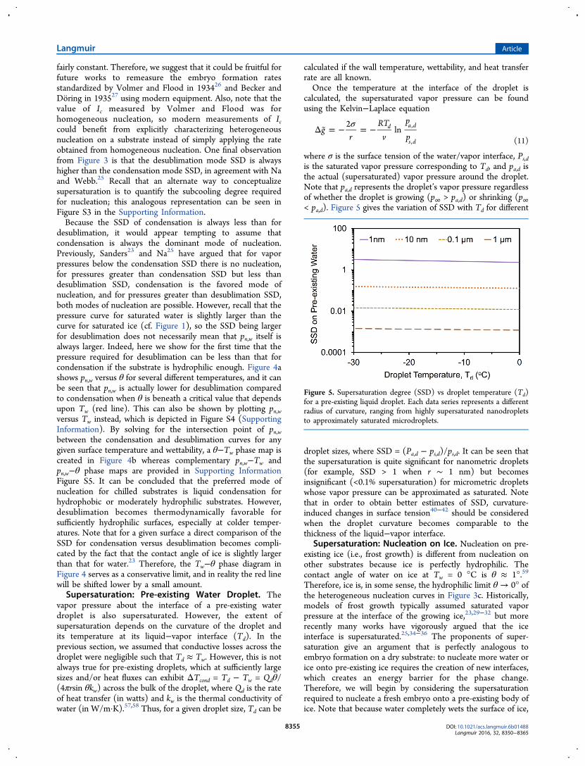
where σ is the surface tension of the water/vapor interface, Ps,dis the saturated vapor pressure corresponding to Td, and pa,d isthe actual (supersaturated) vapor pressure around the droplet.Note that pa,d represents the droplet’s vapor pressure regardlessof whether the droplet is growing (p∞ > pa,d) or shrinking (p∞< pa,d). Figure 5 gives the variation of SSD with Td for different
droplet sizes, where SSD = (Pa,d − ps,d)/ps,d. It can be seen thatthe supersaturation is quite significant for nanometric droplets(for example, SSD > 1 when r ∼ 1 nm) but becomesinsignificant (<0.1% supersaturation) for micrometric dropletswhose vapor pressure can be approximated as saturated. Notethat in order to obtain better estimates of SSD, curvature-induced changes in surface tension40−42 should be consideredwhen the droplet curvature becomes comparable to thethickness of the liquid−vapor interface.
Supersaturation: Nucleation on Ice. Nucleation on pre-existing ice (i.e., frost growth) is different from nucleation onother substrates because ice is perfectly hydrophilic. Thecontact angle of water on ice at Tw = 0 °C is θ ≈ 1°.59
Therefore, ice is, in some sense, the hydrophilic limit θ → 0° ofthe heterogeneous nucleation curves in Figure 3c. Historically,models of frost growth typically assumed saturated vaporpressure at the interface of the growing ice,23,29−32 but morerecently many works have vigorously argued that the iceinterface is supersaturated.25,34−36 The proponents of super-saturation give an argument that is perfectly analogous toembryo formation on a dry substrate: to nucleate more water orice onto pre-existing ice requires the creation of new interfaces,which creates an energy barrier for the phase change.Therefore, we will begin by considering the supersaturationrequired to nucleate a fresh embryo onto a pre-existing body ofice. Note that because water completely wets the surface of ice,
Figure 5. Supersaturation degree (SSD) vs droplet temperature (Td)for a pre-existing liquid droplet. Each data series represents a differentradius of curvature, ranging from highly supersaturated nanodropletsto approximately saturated microdroplets.
Langmuir Article
DOI: 10.1021/acs.langmuir.6b01488Langmuir 2016, 32, 8350−8365
8355

it would be appropriate to adapt a 2D nucleation model in thiscase.Analogous to a dry substrate, nucleation occurring on pre-
existing ice could occur in either the condensation mode ordesublimation mode. Consider an ice droplet of temperature Tiresting on a substrate of temperature Tw. Note that thetemperature Ti of the so-called ice droplet could equally applyto that of a sheet of ice; our droplet terminology here is simplydue to the fact that we are often dealing with recently frozencondensate. For sufficiently large ice droplets/sheets, thetemperature at the ice/vapor interface (Ti) is larger than thewall temperature and could be estimated in the same manner asin the previous section. Assuming that the embryo nucleatingon the ice manifests itself in the shape of a monolayer-thickdisk,25 the total Gibbs energy change for embryo formation is
π π σΔ = Δ +G r a g ar2d d ij2
(12)
where a ≈ 1 Å and rd are the thickness and width of the diskand σ i j is the surface tension of the liquid−vapor(condensation) or ice−vapor (desublimation) interface. Notethat because the “substrate” itself is already composed of ice,the only new interfacial area that had to be considered in eq 12was the sides of the disk embryo. Although it is true that acondensing embryo will replace an ice−vapor interface with anice−liquid liquid−vapor dual interface, these are energeticallyequivalent according to Young’s eq (eq 7) when θ ≈ 0°, whichis the case for water on ice. By setting ∂ΔG/∂rd = 0 to solve forthe critical size of a stable embryo (rd*), the critical Gibbs freeenergy for nucleation is obtained:
σ* = −
Δ r
gdij
(13)
πσΔ * = −
Δ G
a
gij
2
(14)
Using eqs 3, 9, and 14 and replacing Tw by Ti and ps,w by ps,i, wecan write the critical supersaturation pressure for nucleation onpre-existing ice (pn,i) as an analytical expression in Ti
πσ=
*
⎛⎝⎜⎜
⎞⎠⎟⎟p p
N v a
R T Iexp
lnn i s ia ij
i, ,
2
2 2(15)
where Na is Avogadro’s number. Note that this disk embryomodel does not consider the energetics of the quasi-liquid meltlayer that can exist at an ice interface when p∞ is sufficientlylarge.33,59
Before eq 15 can be used, a value for I* = I0/Ic needs to bechosen for the case of nucleation onto an ice substrate. Na andWebb25 used the same values of I0 ∼ 1029m−2s−1 and Ic ∼ 104
m−2s−1 as for the case of nucleation onto a dry substrate but donot provide any justification for doing so.25 In Figure 6, weshow the implications of using the same I* values for ice aswere used for dry surfaces (I* ranging from 1024 to 1027). First,this shows that even on pre-existing ice there is a change in thepreferred nucleation mode between condensation and desu-blimation, with the inflection point denoted by the intersectionof Pn,i. Also note that despite the fact that ice is perfectlyhydrophilic the nucleation pressure is supersaturated for all icetemperatures. This is in sharp contrast to what we obtainedfrom our 3D nucleation model for nucleation on a dry, smoothsurface, where the nucleation pressure becomes saturated (SSD→ 0) as θ → 0° (cf. Figure 3). Though this may be true for the
specific case of nucleation on ice, it is extremely important thatthe choice of I* for an ice substrate is further scrutinized beforeproceeding any further with this model. In the Results sectionbelow, we will probe this question with our experimentalfindings to reveal that the saturated curves (dotted lines inFigure 6) are in fact the most accurate representation of thenucleation pressures for frost growth. In this case, note that thedesublimation is now always the favored nucleation mode onpre-existing ice.
■ EXPERIMENTAL METHODSFour inch silicon wafers (Silicon Quest) were silanized withtrichloro(1H,1H,2H,2H-perfluorooctyl) silane (Sigma-Aldrich) byvapor deposition in a covered-glass Petri dish that was placed on ahot plate set to 70 °C for 1 h. The contact angles were measured witha rame-hart 590 goniometer using the shrink−swell method. Thereceding angle was measured as θr = 89 ± 1°, and the advancing anglewas θa = 113 ± 1°.
Condensation Dry Zones. A freshly prepared hydrophobicsurface was thermally bonded to a Peltier stage (Linkam ScientificPE120) and placed under a top-down optical microscope (NikonEclipse LV150) connected to a digital camera (Phantom v711). Theambient temperature was T∞ = 24.0 °C, and the relative humidity wasH = 26%, which corresponds to a dew point of TDP = 3.3 °C. Thesample was cooled to Tw = −10 °C to observe the growth ofsupercooled condensation.
Interdroplet Ice Bridging. Under the same atmosphericconditions as for the condensation dry zone experiments (T∞ =24.0 °C, H = 26%), the silanized sample was bonded to the Peltier
Figure 6. (a) Schematic of a nucleation process on pre-existing ice. (b)Vapor pressure required for nucleation on pre-existing ice as a functionof the ice temperature (eq 15). Blue/black lines represent the pressureto nucleate water/ice on ice when I* = 1024 (solid lines), I* = 1027
(dashed lines), or under saturated conditions (dotted lines). Assumingsupersaturated conditions, condensation becomes the favorable modeof nucleation on ice above a critical temperature (Ti > −6 °C for I* =1024 or I* = 1027), whereas desublimation always exhibits a lower Pn,ifor nucleation occurring under approximately saturated conditions.Note that the range of temperatures depicted here was intentionallyconstrained to better visualize the intersecting pn,i curves; seeSupporting Information Figure S6 for the full parameter space.
Langmuir Article
DOI: 10.1021/acs.langmuir.6b01488Langmuir 2016, 32, 8350−8365
8356

stage under the top-down optical microscope. The sample was cooledto Tw = −10 °C to grow supercooled condensate. Once freezing wasinitiated in at least one of the condensate droplets (often at the edgesof the silicon wafer), interdroplet ice bridges propagated across thepopulation of supercooled condensate, which was recorded with adigital camera.Dry Zones around a Frozen Droplet. A freshly prepared
hydrophobic surface was thermally bonded to a Peltier stage enclosedinside a rame-hart custom-made humidity chamber. The air temper-ature inside the chamber was Tw = 17.4 °C, and the relative humiditywas set to H = 21%, which corresponds to a dew point of TDP = −5.2°C. A 10 μL droplet of distilled water was deposited on the samplewith the Peltier stage set to Tw = −2.5 °C. The Peltier stage was thencooled to Tw = −12.5 °C, at which point the deposited droplet frozeby heterogeneous nucleation (after about 10 min) while thesurrounding condensate was still unfrozen. Immediately after thedeposited droplet froze, the surrounding condensate evaporated to acertain extent and an annular dry zone was observed.Estimation of Thermal Losses. The thickness of our silicon wafer
samples was tsilicon ≈ 550 μm, and that of the silane monolayer was tsilane≈ 1 nm. The thermal conductivities of silicon and a silane monolayerare known to be ksilicon = 150 W/m·K and ksilane = 0.2 W/m·K,respectively.58 For our experimental conditions, the typical velocity ofvapor was vv ∼ D(p∞ − ps,w)/(ρv RTwζ) ∼ 1 cm/s, where D and ρv arethe diffusivity and density of water vapor, R is the water vapor gasconstant, Tw is the temperature of the substrate, p∞ is the vaporpressure at the boundary layer, ps,w is the saturation vapor pressurecorresponding to the wall temperature, and ζ is the boundary layerthickness.60 For the experimental conditions described above, whereTw = −10 °C and p∞ = 776 Pa, we obtain vv ≈ 3.9 cm/s, whichcorresponds to a low heat flux of q = ρvvvhl,v ≈ 0.56 kW/m2. Thesurface coverage of droplets in dropwise condensation typicallyplateaus around 65%, such that the average heat flux flowing throughthe condensate can be estimated as qd ≈ 0.87 kW/m2. The amount ofheat flux flowing through each droplet can be estimated as Qd = qdπr
2
sin2 θ (in Watts) where r is the radius of curvature and θ is the contact
angle of the drop. The temperature drop across the silicon wafer wasestimated to be ΔTsilicon = Qdtsilicon/(πr
2ksilicon sin2 θ) ≈ 0.003 °C and
the temperature drop across the silane coating was ΔTsilane = Qdtsilane/(πr2ksilane sin
2 θ) ≈ 4.3 × 10⁻⁶ °C. Furthermore, the thermal loss dueto conduction through a micrometric droplet (r = 10 μm and θ ≈ 90°)was estimated as ΔTcond = Qdθ/(4πrkw sin θ) ≈ 0.006 °C. Therefore,because the thermal losses across the substrate, the coating, and thedrop in our system are extremely small, we can assume the droplettemperature to be the same as the temperature at which the Peltierstage was set; that is, Td ≈ Tw for our experiments on the condensationdry zone, interdroplet ice bridging, and dry zones around a frozendroplet.
■ RESULTS AND DISCUSSIONIn the previous section, a model was developed to calculate thevapor pressure field surrounding nucleating or pre-existingwater/ice droplets on a substrate. For a surface containingcondensate droplets of varying sizes or for mixed-mode phasechange systems where supercooled condensate and ice dropletscoexist on a surface, this pressure field will contain localized(interdroplet) pressure gradients that can generate a variety ofinteresting phase-change phenomena. In this section, wecontextualize our model to analyze how these pressuregradients control the behavior of various phenomena such asdry zones, ice bridging, and frost halos.
Condensation Dry Zones. As condensation grows on asubstrate cooled beneath the dew point, vacant spaces formaround nucleating droplets that remain dry (Figure 7a). In anall-liquid condensing system, these dry zones are driven solelyby the difference in supersaturation degree (SSD) betweendroplets of disparate sizes. There exist some rigorouscomputational studies that have solved for the heat transfercoefficients and droplet growth by numerically solving thetransport equations.40,41 Here, we show by simple scaling
Figure 7. (a) Experimental micrograph of droplets condensing on a smooth hydrophobic surface at Tw = −10 °C and p∞ = 776.3 Pa. Theintermediate space between five groups of droplets (A−E, outlined in orange circles) is initially dry, but an increase in their edge-to-edge separationafter coalescence results in the nucleation and growth of a fresh condensate droplet that now lies just outside the dry zone. The scale bar represents20 μm. (b) Schematic of a daughter droplet’s water vapor being harvested by a nearby mother droplet, while at the same time the daughter droplet isbeing fed by the ambient atmosphere. (c) Theoretical model of the nondimensionalized dry zone length, δCr* = δ Cr/ζ (eq 19), around asupersaturated daughter drop surrounded by four saturated mother drops on a θ = 90° substrate (n = 4, β = 0.5). For a fixed ambient pressure p∞ =1169.7 Pa (T∞ = 20 °C, H = 50%), δCr* decays with increasing size of the daughter drop. (d) For a fixed daughter droplet size, r = 100 nm, δ Cr* is nowplotted vs wall temperature for various ambient pressures.
Langmuir Article
DOI: 10.1021/acs.langmuir.6b01488Langmuir 2016, 32, 8350−8365
8357

arguments how we can estimate the dry zone length betweendroplets over a wide parameter space. Consider a motherdroplet exhibiting a radius of curvature rm = 10 μm and atemperature Td at its liquid−vapor interface. Recall from theprevious section that for low heat fluxes this temperature couldbe approximated by the wall temperature, Td ≈ Tw, whereas forhigh heat fluxes the conductive losses would have to beconsidered. Because of its large radius of curvature, the vaporpressure over this mother droplet would be approximatelysaturated, pd ≈ ps,d, because the SSD is negligible formicrometer-sized droplets (eq 11 and Figure 5). Now considera daughter droplet adjacent to the mother droplet that exhibitsa smaller radius of curvature, r < rm, and therefore exhibits alarger vapor pressure, pa,d > ps,d.This in-plane pressure gradient between the daughter and
mother droplet will facilitate the evaporation of the daughterdroplet (Figure 7b)
δ ∼ ∼
−m J A
DRT
p pAl e l e
d
a d s d, ,
, ,
(16)
where ml,e and Jl,e are the mass flow rate and mass flux of theevaporative vapor emanating from the daughter droplet, A∥ isthe in-plane projected area of the daughter drop, D is thediffusivity of water vapor in air, R = 461.5 J/kg·K is the gasconstant of water vapor, and δ is the edge-to-edge separationbetween the mother droplet and the daughter droplet.However, such a daughter drop in general is surrounded by
multiple mother droplets and the total evaporative flux is asummation of all of the individual in-plane mass fluxes. Let n bethe number of closet neighbors where δ1, δ2, δ3,..., δn representthe edge-to-edge distances of the mother droplets from thedaughter droplet:
∑δ δ δ δ
δ
∼
− + + + +
=
−
⎛⎝⎜
⎞⎠⎟m
DRT
p p A
DRT
p pn
A
( )1 1 1
...1
( )
l ed
a d s dn
da d s d
, , ,1 2 3
, ,
(17)
where
δ δ δ δ δ= + + + +
⎛⎝⎜
⎞⎠⎟
n 1 1 1...
1
n1 2 3
such that δ is the harmonic mean of δ1, δ2, δ3,..., δn. Note thatwe need to consider only those mother droplets that are theclosest neighbors. Droplets that have a significantly larger valueof δ have negligible effect on the evaporative flux because thepressure gradient scales as δ−1.For a condensing surface such as this one, the ambient vapor
pressure exceeds the supersaturated pressure of the daughterdroplet (p∞ > pa,d), so the daughter droplet will also be growingas a result of the out-of-plane diffusion of water vapor towardthe substrate
ζ ∼ ∼
−⊥
∞⊥m J A
DRT
p pAl c l c
d
a d, ,
,
(18)
where ml,c and Jl,c now represent the influx of vapor into thecondensing daughter droplet, A⊥ is the out-of-plane projectedarea of the daughter droplet, and ζ is the thickness of theconcentration boundary layer (Figure 7b).
How should we estimate the length of a dry zone around amother droplet? By definition, any droplet that can nucleatewithin the dry zone must exhibit a net outflux of vapor (∑ml,e >ml,c) such that the region would appear to remain dry from amicroscopic point of view. Also by definition, dropletsnucleating outside of the dry zone must be free to grow(∑ml,e < ml,c). Therefore, the periphery of the dry zone must bedefined as the critical distance (δ Cr) from the mother dropletswhere the net in-plane outflux and out-of-plane influx areperfectly balanced (∑ ml,e ∼ ml,c)
δδζ
β* =
∼−
−∞
np p
p pCrCr a d s d
a d
, ,
, (19)
where β = A∥/A⊥ is a geometric prefactor that takes intoaccount the ratio of the in-plane and out-of-plane projectedareas. Following a spherical cap approximation for a droplet,
βθ θ
πθ
πθ π
θπ
θπ
θ π=
− <
+ >
⎜ ⎟⎧⎨⎪⎪
⎩⎪⎪
⎛⎝
⎞⎠cosec
sin 22
, if2
sin 22
, if2
2
(20)
Note that this flux balance approach was first developed byGuadarrama-Cetina et al. to calculate the dry zone around asalty water droplet16 and very recently has been employed byBoreyko et al. to estimate the dry zone around liquid dropletsand ice droplets for a narrow parameter space.2 However, theprevious works had not accounted for the multidroplet effect(n) or the geometric factor (β). The value of β lies between 0and 1, and for θ = π/2, β = 1/2. Because β decreases as θdecreases, this means that the dry zone length on a hydrophilicsubstrate should be substantially smaller than that on ahydrophobic substrate at the same temperature under ambientconditions. Also we see that as θ → 0, β → 0, which implies adry zone length of zero corresponding to filmwise condensationin the hydrophilic limit. The dry zone length increases if thereare multiple nearest neighbors, which is expected becauseincreasing the number of mother droplets is equivalent toincreasing the number of humidity sinks in the system, whichwould increase the net evaporative flux.We now apply eq 19 to a systematic variation of wall
temperatures and sizes of daughter droplets to gain a breadth ofunderstanding of dry zone behavior. Keeping ζ on the left-handside of eq 19 serves the dual purposes of nondimensionalizingthe equation while also rendering the calculation valid for anypossible value of ζ. For a purely diffusive system whereconvective effects are negligible, the concentration boundarylayer thickness ζ can be estimated to within an order ofmagnitude as
ζζ
α∼
−∞
⎡⎣⎢⎢
⎤⎦⎥⎥
D
g T T4 ( )h
w
3/21/3
(21)
where ζh ∼ Ls(gα(T∞ − Tw)Ls3/ν2) −1/5 is the hydrodynamic
boundary layer, α and ν are the volumetric thermal expansioncoefficient and kinematic viscosity of air, and Ls is thecharacteristic length scale of the condensing surface.61 For atypical surface of Ls ≈ 8 cm (also as used in our experiment)and for (T∞ − Tw) as high as 50 °C, the concentrationboundary layer thickness scales as ζ ∼ 1 mm. Note that ζ isindependent of the externally imposed supersaturations andthus a constant in purely diffusive systems.
Langmuir Article
DOI: 10.1021/acs.langmuir.6b01488Langmuir 2016, 32, 8350−8365
8358

This analysis assumed that embryos are able to nucleate nearthe mother droplet in the first place such that a flux balancedefines the dry zone. Immediately after nucleation, condensingdroplets will quickly grow to exhibit a larger radius of curvaturecompared to freshly nucleating droplets; therefore, a dry zoneshould exist around every droplet growing on the surface. Aninteresting observation here is that immediately after acoalescence event occurs on a condensing surface, theinterdroplet distance between the merged droplet and itsneighbors tends to increase. Therefore, if the dry zones aroundneighboring droplets were initially overlapping to a smallextent, a coalescence event is often capable of triggering freshnucleation/growth events on the surface. In the first frame ofFigure 7a, no droplets grow in the intermediate space betweenadjacent mother droplets, which means that the edge-to-edgeseparation between the mother droplets must be smaller than2δCr to promote overlapping dry zones. In the second frame,several pairs of mother droplets have coalesced, increasing theiredge-to-edge separation beyond 2δCr and promoting thenucleation and growth of fresh condensate.On a multidroplet condensing surface, a daughter droplet can
successfully grow only at a location where δexp ≳ δCr. Thedaughter droplet in Figure 7a is successfully growing at alocation that is δA = 12.3 μm, δB = 25.4 μm, δC = 26 μm, δD =21.7 μm, and δE = 39.1 μm away from its nearest-neighbormother droplets labeled A−E, respectively. This yields δexp =21.7 μm. By using eq 19 with ζ ≈ 1 mm and considering an r =100 nm daughter droplet, we obtain a theoretical dry zonelength δCr = 18.9 μm that explains why the daughter droplet issuccessfully growing just outside of this length scale. Note thateven if we choose to exclude the farthest neighbor E from ourcalculations, because δE is more than three times the nearest-neighbor distance δA, we see that δexp ≳ δCr holds. This isbecause for four droplets, δ exp = 19.5 μm and the theoretical δCr= 15.1 μm. This shows the robustness of our proposed model,which captures the effect of interacting pressure fields in amultidroplet system on dry zone lengths. However, the modelis based on simple scaling arguments and more importantly onthe continuum limit where fluxes are governed by eqs 16 and
18. A computational model in this regard40,41 can help shedmore light on the noncontinuum transport effects on dry zonesin the very early stages of nucleation when r ∼ 1−10 nm.In Figure 7c, the length of the nondimensionalized dry zone,
δ Cr* = δCr/ζ, exhibits a power-law slope of −1 as the daughterdroplet increases in size beyond 100 nm. This reveals thatdroplets within the dry zone will evaporate at an acceleratingrate as they disappear. In Figure 7d, δCr* is plotted as a functionof the substrate temperature when the radius of the daughterdrop is fixed at r = 100 nm. For a given p∞, the magnitude ofδ Cr* increases with wall temperature, which is logical given theexponential increase in vapor pressure with temperature, whichserves to increase the interdroplet pressure gradient withrespect to the out-of-plane gradient. It follows that δCr* → ∞ asp∞ approaches the supersaturated vapor pressure at theinterface of the daughter drop. Figure 7d also illustrates howfor a fixed radius of the daughter drop, δCr* decreases withincreasing p∞ because of the out-of-plane pressure gradientbecoming more dominant over the in-plane gradient.Finally, we should mention that a second type of dry zone is
also possible, in which nucleation itself is not possible as aresult of the elevated pressure required for nucleation (Pn,w)relative to the saturation pressure of the large mother droplet(ps,d). Here, we focused on the flux dry zone because it hasoften been ignored in recent works that have exclusivelyconsidered the nucleation dry zone.4,17−19,61 Both dry zones areof course possible, with the outer perimeter of the absolute dryzone being defined by whichever is larger. A detailed analysis ofthe competition between nucleation dry zones and flux dryzones, particularly for r ∼ 1−10 nm droplets, is outside thescope of the present work and will be the primary focus of afuture investigation.Also note that in the present discussion as well as in the
subsequent sections we do not consider the effects ofnoncondensable gases in the system. It is well known thatnoncondensable gas concentrates at the condensing surface,thereby increasing the vapor diffusion resistance and thecondensation heat transfer coefficient. However, how exactly
Figure 8. (a) Experimental and schematic depiction of the two different regimes of ice bridging that occur between a frozen droplet and asupercooled liquid droplet. Experiments were performed at Tw = −10 °C and p∞ = 776.3 Pa; time stamps are in seconds, and the scale bar represents20 μm. (b) Theoretical difference between the saturation vapor pressure of water and the pressure required to nucleate on ice plotted with respect totemperature for different values of I* (eq 15). The blue and black lines represent the condensation and desublimation modes of nucleation on ice,respectively. The gray line tracks the inflection points where the change in the favorable mode of embryo nucleation on ice occurs for different I*values. The solid line corresponds to I* = 1025, as used by Na et al.25 for nucleation on ice. This gives a negative value of ps,l − pn,i for Tw > − 15 °C,which is implausible given that ice bridging occurs at warmer temperatures. The dotted line represents I* = 1035, which is the lowest value of I* thatallows for ice bridging up to Tw = −10 °C. The I* = 10219 curve (dotted and dashed) corresponds to the minimum value of ps,l − pn,i = 264.6 Painferred from experimental measurements of bridge growth rates at Tw = −10 °C as obtained previously by Boreyko and Collier7 and correlated withour diffusive scaling model (eq 25). Finally, I* → ∞ (dashed) corresponds to saturated conditions at the growing ice interface (pn,i ≈ ps,i), which wesuggest is the best approximation.
Langmuir Article
DOI: 10.1021/acs.langmuir.6b01488Langmuir 2016, 32, 8350−8365
8359

that would influence dry zone lengths is a nontrivial problemand requires further investigation.Interdroplet Ice Bridging. From this point onward, we
analyze the more complex case of multiphase systems wheresupercooled liquid droplets and frozen ice droplets coexist on asubfreezing substrate. Recall that interdroplet ice bridging fromfrozen droplets to neighboring liquid droplets is the dominantmechanism for the condensation frosting of surfaces chilledbeneath the dew point.7,8 Because of the depressed vaporpressure of ice relative to water, the water molecules growing anice bridge are being harvested from the liquid droplet that thebridge is growing toward.Whether an individual ice bridge is able to freeze its targeted
droplet can be predicted by considering the limiting case of thebridge connecting to the liquid droplet just before it hascompletely evaporated.7 At this critical limit, the mass of thecompleted ice bridge, mbridge, equals the mass of the liquiddroplet being harvested, ml. Also, under this limiting condition,the length of the ice bridge L attains its maximum possiblevalue Lmax, which is equal to the distance between the edge ofthe frozen droplet and the center of the liquid droplet. Weconsider the case of a pair of identical droplets, one frozen andthe other unfrozen. The mass of the liquid droplet beingharvested scales as ml ∼ ρld
3, where d is the initial (projected)diameter of the liquid droplet prior to harvesting. The mass ofthe ice bridge scales as mbridge ∼ ρiLmaxd
2. Equating the requiredmass for a completed ice bridge with the mass of the liquiddroplet being harvested therefore predicts that if Lmax < d thenan ice bridge can connect to the liquid droplet being harvestedand if Lmax > d then it cannot and the droplet completelyevaporates (Figure 8a). This mass scaling is only a goodapproximation for a single-pair interaction of droplets that areapproximately equal in size. Also, this model is valid only fordroplets with large contact angles, but this restriction isappropriate given that interdroplet frost growth typically occurson hydrophobic and superhydrophobic surfaces. On sufficientlyhydrophilic surfaces, the supercooled condensate tends to growas a uniform film of water, which freezes over all at once.62
Here, we focus on the former case of interdroplet frost growthwhere Lmax < d.How can the interdroplet pressure gradient be related to the
growth rate of an ice bridge? Consider a liquid droplet adjacentto another droplet that has frozen over at some initial time t0 =0; the in-plane mass flux of the evaporating liquid droplet scalesas
δ ∼ ∼
−m J A
DRT
p pAl e l e
w
s l n i, ,
, ,
(22)
where ps,l is the saturation pressure of the (presumablymicrometric) liquid droplet, pn,i is the unknown vapor pressureadjacent to the interface of the ice droplet and growing icebridge, δ is the edge-to-edge interdroplet separation, and A∥ isthe in-plane projected area of the liquid droplet, and it ispresumed that the droplet temperatures are approximatelyequal to the wall temperature. The in-plane mass flux of vaporgrowing the ice bridge is
ρ ∼m v Ai c i b, (23)
where vb is the in-plane growth rate of the bridge and A∥ is thein-plane projected area of the frozen droplet. By conservationof mass, ml,e ∼ mi,c. When the frozen droplet and (initial) liquid
droplet are approximately the same size, equating eqs 22 and 23yields the following characteristic velocity of ice bridge growth:
ρ δ∼
−v
DRT
p pb
i w
s l n i, ,
(24)
Recall that the pressure differential ps,l − pn,i is a function oftemperature, so eq 24 reveals that vb should simply scaleinversely with δ while also exhibiting a more analyticallycomplex dependence on Tw. An interesting observationregarding eq 24 is that the partial pressure of water vapor inthe ambient atmosphere (P∞) does not appear to have anyeffect on the propagation speed of the ice bridge, which islogical given that the bridge is entirely fueled by the liquiddroplet.7 However, note that extremely large values of P∞would serve to reduce the net evaporation rate of the liquiddroplet being harvested by an ice droplet/bridge such that therule in which bridging fails for Lmax > d may eventually breakdown.The choice of time-independent δ as the length scale over
which the pressure gradient acts during bridging merits a briefdiscussion. Although it is true that the absolute distancebetween the liquid and ice decreases over time during bridging,conservation of mass mandates that the vapor harvested fromthe liquid droplet is flowing toward the ice through a projectedarea of d2. Consequently, the vast majority of vapor flowsbeyond the tapered tip of the ice bridge before depositingsomewhere further down the ice bridge. Because this model isrestricted to the scenario of short interdroplet distances wherebridges are always successful (Lmax < d), the majority of thevapor will therefore deposit somewhere very close to the baseof the bridge near the original perimeter of the ice droplet suchthat the pressure gradient can be held as constant to within anorder of magnitude. By extension, the constant pressuregradient in eq 24 necessitates that vb is approximately constantover time for bridging between a given pair of isothermaldroplets (i.e., for a fixed choice of δ and Tw). This can berepresented as vb = dx/dt, where vb is time-independent, x(t) isthe evolving length of the growing ice bridge with boundarycondition x(0) = 0, and x(τ) = L at the point of connection attime t = τ. The final length of a completed ice bridge relative tothe interdroplet spacing can vary slightly, ranging from L → δfor Lmax ≪ d (where evaporation is negligible) up to L → Lmaxat the critical limit of Lmax → d.Recall that it remains an open question as to whether the
vapor pressure at the interface of growing frost is saturated orsupersaturated. This issue is difficult to settle for the moreconventional case of a macroscopic sheet of ice growing out ofplane on a substrate because matching the experimentallymeasured growth rates with a theoretical model can besimultaneously accomplished by assigning a supersaturatedvapor pressure to the model or by modifying the diffusionresistance factor, which is a function of the porosity/density ofthe ice sheet used in the model.63 Here, we will demonstratethat the phenomenon of interdroplet ice bridging can resolvethis long-standing question of the vapor pressure required togrow ice.Over the past several years, it has been repeatedly observed
that ice droplets are able to grow ice bridges by siphoning watervapor from neighboring liquid droplets over a wide range ofsubfreezing surface temperatures, surface wettabilities, andambient vapor pressures.2,7−14 It should be emphasized that theambient water vapor is not contributing appreciably to the
Langmuir Article
DOI: 10.1021/acs.langmuir.6b01488Langmuir 2016, 32, 8350−8365
8360

growth of these interdroplet ice bridges because bridge growthis in-plane and exactly in the direction of the liquid dropletbeing harvested.7 Therefore, it can be asserted with extremeconfidence that the vapor pressure around the ice droplets (andbridges) must be lower than the vapor pressure around theliquid droplets; otherwise, this source-sink behavior would beimpossible. Previous reports have observed interdroplet icebridging across populations of microscopic or even macro-scopic condensate droplets;7,8 recall from Figure 5 that liquiddroplets of this size exhibit a saturated vapor pressure.However, when using Na’s assumption of I* = 1025 to estimatethe vapor pressure around growing frost,25 ps,l − pn,i is negativefor all temperatures Tw > −15 °C (Figure 8b, solid line), whichimplies that interdroplet ice bridging is impossible above −15°C. This is in contrast to the findings of Boreyko and Collier,where interdroplet ice bridging was readily observed at Tw =−10 °C.7
Therefore, we now have experimental evidence that I* ∼1025 is not a good assumption when considering nucleation onice. To satisfy the criteria ps,l − pn,i > 0 at Tw = −10 °C, thelowest possible value of the embryo kinetics is ICr* ∼ 1035
(dotted line in Figure 8b). This corresponds to a maximumpossible SSD over ice of SSDCr ≈ 0.1 at Tw = −10 °C. Byreferring to experimentally measured bridge growth rates (vb,exp= L(τ)exp/τexp), interdroplet spacings (δexp), and wall temper-atures (Tw,exp) previously obtained from Boreyko and Collier,7
the vapor pressure difference driving the growth of interdropletfrost growth can be estimated as
δρ
− =⎛
⎝⎜⎜⎞⎠⎟⎟p p
RT
Dvs l n i exp
i w expb exp, ,
,,
(25)
At Tw = −10 °C, experimental measurements used in eq 25predict a pressure differential of ps,l − pn,i = 21.8 Pa,corresponding to the experimentally obtained minimum bridgegrowth rate of vb = 0.4 μm/s for an average δexp = 9.8 μm. Thiscorresponds to I* ∼ 10219 (Figure 8b, dashed and dotted line)and SSD = 0.018. For I0 = 1029 m−2 s−1, it follows that Ic =10−190 m−2 s−1. Such a small value of Ic means that thethreshold rate at which embryos spontaneously nucleate isessentially zero. Correspondingly, for Ic → 0, we have pn,i → ps,isuch that the vapor pressure at the interface of the growing ice
can be considered to be saturated for all intents and purposes(dashed line in Figure 8b). This is also consistent with ourobservation that for heterogeneous nucleation on a substrate,SSD → 0 in the hydrophilic limit θ → 0 (Figure 3). Thus, wepropose that the vapor pressure adjacent to growing frost isapproximately saturated, in agreement with an extremely recentwork that used laser confocal microscopy and differentialinterference contrast microscopy to observe that the equili-brium pressure of ice is indeed aligned with the saturationcurve.33
Dry Zone around Frozen Droplets. During condensationfrosting, where ice bridges grow across a population ofsupercooled condensate, it is possible to observe individualice bridges failing to connect for interdroplet distances beyondthe threshold value (Lmax > d). These local incidents ofcomplete evaporation of the condensate serve to slightly retardthe velocity of the global freeze front. However, it has beenreported that bridging is typically successful for nearly all of thedroplets on a hydrophobic surface.7,8 Even for a jumping-droplet superhydrophobic surface exhibiting maximal inter-droplet separations,64 ice bridges are still able to propagateacross roughly one-third of the droplets.7 Very recently, wedemonstrated that interdroplet ice bridging can be completelysuppressed when the freezing event occurs at an early point inthe growth of condensation, particularly when using chemicalpatterns that maximize the interdroplet separations.2 In thisscenario, all water droplets neighboring the piece of icecompletely evaporate, leaving a stable dry zone around the iceanalogous to the dry zone around liquid droplets.Figure 9a shows an example of such a dry zone. Instead of
using the chemical micropatterns and triggered freezingtechniques from before,2 here a Peltier stage enclosed in ahumidity chamber was employed. A dry zone around a singleice droplet is easily obtained by depositing a water droplet ontoa smooth hydrophobic surface bonded to a Peltier stage,freezing the droplet by bringing the Peltier stage to a chilledtemperature while keeping the chamber dry, and thenincreasing the humidity to allow supercooled condensation toform on the surface.The plateau dry zone length around a frozen droplet, δCr, can
be predicted by balancing the fluxes of a liquid droplet at theborder of the dry zone. This is analogous to the model used
Figure 9. (a) Experimental micrograph of a dry zone of length δCr = 354 μm between ice and supercooled condensation, where no condensation orfrost can grow. Here Tw = −12.5 °C, T∞ = 17.4 °C, H = 21%, and p∞ = 417.5 Pa. (b) Theoretical nondimensionalized dry zone length, δCr* = δCr/ζ(eq 26), as a function of wall temperature when the ice is considered to be saturated (solid red line) or supersaturated (solid and dotted black lines)on a hydrophobic substrate with β = 0.5. Droplets nucleating outside of the dry zone (white region) will exhibit net growth, and droplets nucleatingwithin the dry zone (shaded regions) will evaporate. Daughter droplets were assumed to be of size r ∼ 100 nm, and the ambient conditions weretaken to be T∞ = 20 °C and H = 50%, corresponding to p∞ = 1169.7 Pa. (c) Variation of theoretical δCr* with ambient vapor pressure for severaldifferent substrate temperatures. Here, the ice is considered to be saturated, and the size of the liquid droplet is still r ∼ 100 nm.
Langmuir Article
DOI: 10.1021/acs.langmuir.6b01488Langmuir 2016, 32, 8350−8365
8361

above for liquid dry zones. A daughter drop at the periphery ofthe dry zone is surrounded on one side by water drops and onthe other side by a single frozen drop. With this configuration,the in-plane evaporative flux is caused by the difference insaturation pressures between water and ice (cf. Figure 1). For agrowing ice droplet with vapor pressure pn,i and a liquid dropletof pressure pa,d, the nondimensionalized dry zone length can beobtained:
δδζ
β* = ∼−
−∞
p p
p pCrCr a d n i
a d
, ,
, (26)
As always, note that pa,d will be supersaturated for nanometricdroplets and saturated (pa,d ≈ ps,d) for larger droplets (Figure5). Inspired by the interdroplet ice bridging analysis performedin the previous section, we suggest that the vapor pressurearound the ice droplet is approximately saturated, pn,i ≈ ps,i (I*→ ∞). However, here too we can test the validity of theassumption of supersaturated frost growth based on I* valuesranging from 1024 to 1027 (as used in heterogeneousnucleation) by comparing their predicted dry zone lengthswith experiments.In Figure 9a, the dry zone between the ice droplet and visible
microscopic condensate is measured to be δCr = 354 μm for theexperimental conditions of Tw = −12.5 °C and p∞ = 417.5 Pa.Using eq 26 for β = 0.5 and saturated conditions about the icedroplet at Tw = −12.5 °C, the experimentally observed dry zonelength corresponds to a boundary layer thickness of ζ = 4.3mm. This agrees with our theoretical estimation of ζ ∼ 1 mm(eq 21) to within its order of magnitude.2,61 For I* = 1024,there should be no dry zone at all because pn,i > pa,d. For I* =1027, the experimentally observed dry zone length of δCr = 354μm corresponds to a boundary layer thickness of ζ = 171.9 mm,which is an implausible 2 orders of magnitude higher than thepredicted ζ ∼ 1 mm. This further supports our hypothesis thatthe vapor pressure at the interface of growing ice is notsupersaturated to any appreciable extent.Figure 9b depicts the dimensionless dry zone length as a
function of wall temperature for a fixed value of p∞. The vaporpressure of the daughter droplet corresponds to r ∼ 100 nm(Condensation Dry Zones section). The δCr* variation withtemperature shows a trend similar to that of the saturationpressure difference between water and ice as observed in Figure1. This is because the low degree of supersaturation on the
liquid droplet of r ∼ 100 nm is not sufficient to change thenature of the inherent difference in the saturation pressures,though it does shift the peak closer to 0 °C. In addition todepicting the dry zone lengths, Figure 9b can also beconsidered to be a phase map describing the behavior of thesurface on either side of the dry zone calculated on the basis ofthe saturation vapor pressure of ice (red line). Condensatedroplets located at some value δ < δCr will evaporate, butdroplets located at δ > δCr will be free to grow. When I* = 1027
or I* = 1024 is chosen (black lines), the graph reveals that thereshould be no dry zone for Tw > −13.5 °C or Tw > −12 °C,respectively. This is obviously incorrect, given the large dryzone experimentally observed at Tw = −12.5 °C, providingmore evidence for the saturated ice hypothesis.Figure 9c depicts δCr* as a function of P∞ for various values of
Tw. It is still assumed that the liquid droplet is of size r ∼ 100nm and the ice is assumed to be saturated, pn,i ≈ ps,i. Asexpected, drier ambient environments correspond to larger dryzones as the in-plane pressure gradient becomes moredominant. As mandated by eq 26, it can be seen that δCr*exhibits asymptotic behavior as p∞ → pa,d. This asymptoticbehavior of δCr* occurs at higher values of p∞ for highersubstrate temperatures as pa,d increases exponentially withtemperature. In Figure 9b, we saw that for a given p∞ the samedry zone length can be observed for two different temperaturesbefore and after the peak (around Tw ≈ −7.5 °C). This is whywe see the 0 °C curve in Figure 9c intersecting with the curvescorresponding to −10, −20, and −30 °C at ambient pressureswhere the 0 °C curve exhibits the same dry zone lengths thatthey exhibit.
Frost Halos. For the isothermal case of all dropletsexhibiting the same approximate temperature as the chilledsubstrate, it seems nearly universal that the vapor pressure ofthe ice droplets is lower than that of the supercooled liquiddroplets. This leads to the ice bridging and dry zone behaviorsthat have already been discussed here. But is it possible toinvert this pressure gradient? A keen observation by Jung et al.has revealed that pi > pl is indeed possible during the initialfreezing of a supercooled droplet, causing vapor to be rapidlyexpelled from the freezing droplet and condense on thesubstrate around the droplet.20 Once the droplet has finishedfreezing, it grows bridges to freeze the surrounding ring ofsatellite condensation, hence the term frost halo.20,21 Here, weapply our vapor pressure model to the context of frost halos to
Figure 10. (a) Schematic of a supercooled droplet after its initial stage of freezing, where the droplet temperature and vapor pressure are rapidlyincreased to Ti ≈ 0 °C and Pi,0 ≈ 611 Pa, respectively. (b) Difference between the vapor pressure of the freezing droplet and the pressure required tonucleate an embryo on the substrate, calculated from eq 10 and plotted as a function of the substrate wettability. Blue and black curves correspond tothe nucleation pressure for condensation versus desublimation; positive values correspond to when nucleation is possible. (c) Phase map thatpredicts when desublimation halos (red region), condensation halos (blue), or no halos (white) should form around a freezing droplet, as a functionof the surface temperature and wettability.
Langmuir Article
DOI: 10.1021/acs.langmuir.6b01488Langmuir 2016, 32, 8350−8365
8362
gain some fundamental insights regarding the phase spacewhere the phenomenon can occur.Inspired by the observations of the frost halo, Figure 10a
depicts a droplet that has just finished the initial recalescentstage of freezing where a thin shell of ice surrounds the droplet.Because of the latent heat deposited during first-stage freezing,the temperature of the droplet rapidly increases from Td ≈ Twup to Ti ≈ 0 °C. Note that the duration of time where Ti ≈ 0°C can range from fractions of a second to tens of seconds,depending on the thermal conductivity of the underlyingsubstrate. This heat transfer time scale must be larger than thevapor diffusion time scale in order for the halo effect to bepossible.20,65 As justified above, let us assume that the vaporpressure around this recalescent droplet corresponds to thesaturation pressure of ice: pi,0 ≈ (ps,i)T=0 °C = 611.2 Pa.Therefore, the nucleation of embryos on the substrate aroundthe freezing droplet should be possible when
π σ> + −
⎛
⎝⎜⎜⎜
⎞
⎠⎟⎟⎟( )
p pv
RT kTm mexp
43 ln
(2 )(1 )i s ww
ij
wII
,0 ,
32
0
(27)
where the right-hand side of the equation corresponds to thecritical pressure pn,w required for nucleation (cf. eq 10).In Figure 10b, we show where pi,0 − pn,w attains a positive
value (thus fulfilling the criteria for nucleation) as a function ofθ for multiple values of Tw. Both the condensation (blue lines)and desublimation (black lines) modes of nucleation areconsidered, where the preferred mode corresponds towhichever curve exhibits a lower value of pn,w (and hence alarger value of pi,0 − pn,w) for given values of θ and Tw. Figure10b reveals that for a given surface temperature there exists acritical contact angle above which nucleation cannot occur; thiscritical θ corresponds to where each curve intercepts the x axis.These findings suggest that the halo effect should be suppressedfor sufficiently hydrophobic surfaces (aside from surfacedefects), particularly for wall temperatures approaching Tw →0 °C. As a validation of our theoretical predictions, we compareour findings with the experimental conditions where Jung et al.observed frost halos.20 In their experiments, Tw = −14.5 °C andθ ≈ 72°. For a surface temperature of Tw = −14.5 °C, ourmodel predicts that the largest contact angle surface where thehalo effect can be observed should correspond to 86° < θmax <90° for 1024 < I* < 1027. Therefore, their observation of halosforming for a surface wettability of θ = 72° is in agreement withour model.By calculating the critical wettability for every possible wall
temperature, a complete phase map was constructed as shownin Figure 10c. The blue and black lines represent the critical Tw− θ curves beneath which condensation and desublimation canoccur, respectively. In other words, beneath these critical curvesthe pi,0 > pn,w condition for nucleation is fulfilled. To determinewhich mode of nucleation is favorable, the critical Tw − θ curvefrom Figure 4b is added to the phase map (red lines), wherethe condensation mode is favored above the curve anddesublimation is favored below. By considering these criticalcurves in conjunction with each other, the phase map cantheoretically predict whether no halo, a condensation halo, or adesublimation halo should occur upon the freezing of asupercooled droplet. It should be noted that the experiments ofJung et al. were over a narrow parameter space that
demonstrated only a condensation halo,20 so the predictionof a desublimation halo has yet to be experimentally validated.
■ CONCLUSIONSWe have developed a comprehensive model to calculate thepressure field of water vapor over a substrate exhibitingcondensation, ice, and/or frost, which has been used to makepredictions and phase maps for phenomena including dryzones, interdroplet frost growth, and frost halos. Key findingscan be summarized as follows.(1) The supersaturation degree (SSD) required for
nucleation on a substrate was calculated as a function ofsurface temperature and wettability. Although we agree with aprevious report that SSD is always higher for desublimationthan for condensation,25 by considering the SSD in conjunctionwith the difference in saturation pressure between water and icewe showed that desublimation can actually be the thermody-namically favorable mode of nucleation at sufficiently lowsurface temperatures and wettabilities. This is in contrast toprevious reports that stated that condensation is always thefavored mode of nucleation.(2) The SSD around pre-existing droplets can be calculated
for liquid droplets using the Kelvin−Laplace equation and forfrost by considering the free energy required to nucleate a disk-shaped embryo on top of the ice. Unlike with a dry substrate,the kinetics of embryo formation on ice are not known andtherefore the extent of supersaturation required to grow frosthas been a long-standing debate. Here, we used experimentalmeasurements of interdroplet ice bridging, which are highlysensitive to vapor pressure, to demonstrate that the vaporpressure at the ice-vapor interface must be approximatelysaturated. This also suggests that desublimation on ice shouldalways be the thermodynamically favorable mode of nucleation.Although the growing frost considered here was in the contextof ice bridges, we expect that our finding of saturated vaporconditions should extend to more general cases such asmacroscopic frost sheets.(3) Annular dry zones around droplets can materialize even
for surfaces cooled well beneath the dew point. Forcondensation, these dry zones are due to the depressed (i.e.,saturated) vapor pressure of larger pre-existing droplets withrespect to the supersaturated pressure of smaller, recentlynucleated droplets. Dry zones can also form between an icedroplet and the surrounding supercooled condensation as aresult of the decreased saturation pressure of ice with respect toliquid water at the same temperature. The steady-state length ofa dry zone was estimated by considering droplets at theperimeter of the dry zone, where the out-of-plane influx ofvapor from the ambient atmosphere matches the in-planeoutflux of vapor toward the droplet acting as a humidity sink.(4) Interdroplet ice bridging between a frozen condensate
and a neighboring liquid condensate has been known to be theprimary mechanism of in-plane frost growth on nonwettingsurfaces for several years,7,8 but a fundamental understanding ofthe bridging kinetics is lacking. Here, by using our pressure fieldmodel in conjunction with diffusive scaling arguments, weobtained an analytical expression for the effective growthvelocity of ice bridging.(5) A phase map was created to model the recently reported
frost halo effect,20 where the rapid increase in temperature andvapor pressure of a freezing droplet can illicit a ring ofnucleation on the surrounding substrate. We find that threeregimes are possible depending on the temperature and
Langmuir Article
DOI: 10.1021/acs.langmuir.6b01488Langmuir 2016, 32, 8350−8365
8363

wettability of the substrate: no halo, a condensation halo, or adesublimation halo. To our knowledge, this is the first mentionof a desublimation halo being possible, which we hope willinspire experimental validation.It is now clear that dry zones, ice bridges, and frost halos are
all governed by localized in-plane pressure gradients, such thatthese phenomena need to be simultaneously examined fromboth fundamental and experimental perspectives. Indeed, justas this fundamental study was inspired by recent experimentsdemonstrating these emerging phase-change phenomena, wehope that this model in turn will inspire the design of futureexperiments that can fully exploit these vapor pressuregradients to gain an unprecedented level of control overcondensation and frost formation on surfaces.
■ ASSOCIATED CONTENT
*S Supporting InformationThe Supporting Information is available free of charge on theACS Publications website at DOI: 10.1021/acs.lang-muir.6b01488.
Overview of the article’s nomenclature and eqs S1−S6and Figures S1−S6 as mentioned in the text (PDF)
■ AUTHOR INFORMATION
Corresponding Author*E-mail: [email protected].
NotesThe authors declare no competing financial interest.
■ ACKNOWLEDGMENTS
We thank Caitlin Bisbano for helping with the dry zoneexperiment in the humidity chamber. We also acknowledgestartup funds from the Department of Biomedical Engineeringand Mechanics at Virginia Tech.
■ REFERENCES(1) Schafle, C.; Bechinger, C.; Rinn, B.; David, C.; Leiderer, P.Cooperative evaporation in ordered arrays of volatile droplets. Phys.Rev. Lett. 1999, 83, 5302−5305.(2) Boreyko, J. B.; Hansen, R. R.; Murphy, K. R.; Nath, S.; Retterer,S. T.; Collier, C. P. Controlling condensation and frost growth withchemical micropatterns. Sci. Rep. 2016, 6, 19131.(3) Schafle, C.; Leiderer, P.; Bechinger, C. Subpattern formationduring condensation processes on structured surfaces. Europhys. Lett.2003, 63, 394−400.(4) Leach, R. N.; Stevens, F.; Langford, S. C.; Dickinson, J. T.Dropwise condensation: experiments and simulations of nucleationand growth of water drops in a cooling system. Langmuir 2006, 22,8864−8872.(5) Murphy, D. M.; Koop, T. Review of the vapour pressures of iceand supercooled water for atmospheric applications. Q. J. R. Meteorol.Soc. 2005, 131, 1539−1565.(6) Dooley, J. B. Determination and characterization of icepropagation mechanisms on surfaces undergoing dropwise condensa-tion. Ph.D. thesis, Texas A&M, 2010.(7) Boreyko, J. B.; Collier, C. P. Delayed frost growth on jumping-drop superhydrophobic surfaces. ACS Nano 2013, 7, 1618−1627.(8) Guadarrama-Cetina, J.; Mongruel, A.; Gonzalez-Vinas, W.;Beysens, D. Percolation-induced frost formation. Europhys. Lett.2013, 101, 16009.(9) Petit, J.; Bonaccurso, E. General frost growth mechanism on solidsubstrates with different stiffness. Langmuir 2014, 30, 1160−1168.
(10) Chen, X.; Ma, R.; Zhou, H.; Zhou, X.; Che, L.; Yao, S.; Wang, Z.Activating the microscale edge effect in a hierarchical surface forfrosting suppression and defrosting promotion. Sci. Rep. 2013, 3, 2515.(11) Boreyko, J. B.; Srijanto, B. R.; Nguyen, T. D.; Vega, C.; Fuentes-Cabrera, M.; Collier, C. P. Dynamic defrosting on nanostructuredsuperhydrophobic surfaces. Langmuir 2013, 29, 9516−9524.(12) Hao, Q.; Pang, Y.; Zhao, Y.; Zhang, J.; Feng, J.; Yao, S.Mechanism of delayed frost growth on superhydrophobic surfaces withjumping condensates: more than interdrop freezing. Langmuir 2014,30, 15416−15422.(13) Kim, A.; Lee, C.; Kim, H.; Kim, J. Simple approach tosuperhydrophobic nanostructured Al for practical antifrostingapplication based on enhanced self-propelled jumping droplets. ACSAppl. Mater. Interfaces 2015, 7, 7206−7213.(14) Zhao, Y.; Yang, C. Retarded condensate freezing propagation onsuperhydrophobic surfaces patterned with micropillars. Appl. Phys.Lett. 2016, 108, 061605.(15) Williams, R.; Blanc, J. Inhibition of water condensation by asoluble salt nucleus. J. Chem. Phys. 1981, 74, 4675−4677.(16) Guadarrama-Cetina, J.; Mongruel, A.; Gonzalez-Vinas, W.;Beysens, D. Frost formation with salt. Europhys. Lett. 2015, 110,56002.(17) Guadarrama-Cetina, J.; Narhe, R. D.; Beysens, D. A.; Gonzalez-Vinas, W. Droplet pattern and condensation gradient around ahumidity sink. Phys. Rev. E 2014, 89, 012402.(18) Biswas, S.; Chakrabarti, A.; Chateauminois, A.; Wandersman, E.;Prevost, A. M.; Chaudhury, M. K. Soft lithography using nectardroplets. Langmuir 2015, 31, 13155−13164.(19) Sun, X.; Damle, V. G.; Uppal, A.; Linder, R.; Chandrashekar, S.;Mohan, A. R.; Rykaczewski, K. Inhibition of condensation frosting byarrays of hygroscopic antifreeze drops. Langmuir 2015, 31, 13743−13752.(20) Jung, S.; Tiwari, M. K.; Poulikakos, D. Frost halos fromsupercooled water droplets. Proc. Natl. Acad. Sci. U. S. A. 2012, 109,16073−16078.(21) Boinovich, L.; Emelyanenko, A. M. Role of water vapordesublimation in the adhesion of an iced droplet to a super-hydrophobic surface. Langmuir 2014, 30, 12596−12601.(22) Fletcher, N. H. Physics of Rain Clouds; Cambridge UniversityPress: Cambridge, U.K., 1962.(23) Sanders, C. T. The influence of frost formation and defrostingon the performance of air coolers. Ph.D. thesis, Delft University ofTechnology, 1974.(24) Piucco, R. O.; Hermes, C. J. L.; Melo, C.; Barbosa, J. R. A studyof frost nucleation on flat surfaces. Exp. Therm. Fluid Sci. 2008, 32,1710−1715.(25) Na, B.; Webb, R. L. A fundamental understanding of factorsaffecting frost nucleation. Int. J. Heat Mass Transfer 2003, 46, 3797−3808.(26) Volmer, M.; Flood, H. Tropfchenbildung in Dampfen. Z. Phys.Chem. A 1934, 170, 273−285.(27) Adamson, A. W.; Gast, A. P. Physical Chemistry of Surfaces, 6thed.; Wiley, 1997.(28) Carey, V. P. Liquid-Vapor Phase-Change Phenomena, 2nd ed.;CRC Press, 2007.(29) Brian, P. L. T.; Reid, R. C.; Shah, Y. T. Frost deposition on coldsurfaces. Ind. Eng. Chem. Fundam. 1970, 9, 375−380.(30) Jones, B. W.; Parker, J. D. Frost formation with varyingenvironmental parameters. J. Heat Transfer 1975, 97, 255−259.(31) Gall, R. L.; Grillot, J. M.; Jallut, C. Modelling of frost growth anddensification. Int. J. Heat Mass Transfer 1997, 40, 3177−3187.(32) Lee, K. S.; Jhee, S.; Yang, D. K. Prediction of the frost formationon a cold flat surface. Int. J. Heat Mass Transfer 2003, 46, 3789−3796.(33) Asakawa, H.; Sazaki, G.; Nagashima, K.; Nakatsubo, S.;Furukawa, Y. Two types of quasi-liquid layers on ice crystals areformed kinetically. Proc. Natl. Acad. Sci. U. S. A. 2016, 113, 1749−1753.(34) Fletcher, N. H. The Chemical Physics of Ice; CambridgeUniversity Press: Cambridge, U.K., 1970.
Langmuir Article
DOI: 10.1021/acs.langmuir.6b01488Langmuir 2016, 32, 8350−8365
8364

(35) Na, B.; Webb, R. L. New model for frost growth rate. Int. J. HeatMass Transfer 2004, 47, 925−936.(36) Cheikh, A. E.; Jacobi, A. A mathematical model for frost growthand densification on flat surfaces. Int. J. Heat Mass Transfer 2014, 77,604−611.(37) Guildner, L. A.; Johnson, D. P.; Jones, F. E. Vapor pressure ofwater at its triple point: highly accurate value. Science 1976, 191,1261−1261.(38) Sassen, K.; Dodd, G. C. Homogeneous nucleation rate forhighly supercooled cirrus cloud droplets. J. Atmos. Sci. 1988, 45, 1357−1369.(39) Peter, T.; Marcolli, C.; Spichtinger, P.; Corti, T.; Baker, M. B.;Koop, T. When dry air is too humid. Science 2006, 314, 1399−1402.(40) Mendoza, H.; Carey, V. P. A DSMC model on droplet clustersto explore the limiting factors of modified surfaces promotingenhanced dropwise condensation. ASME International MechanicalEngineering Congress and Exposition, 2015; p V08AT10A035.(41) Mendoza, H.; Beaini, S.; Carey, V. P. An exploration oftransport within micro and nano droplet clusters during dropwisecondensation of water on nanostructured surfaces. ASME InternationalMechanical Engineering Congress and Exposition, 2011; pp 589−600.(42) Bruot, N.; Caupin, F. Curvature Dependence of the Liquid-Vapor Surface Tension beyond the Tolman Approximation. Phys. Rev.Lett. 2016, 116, 056102.(43) Miljkovic, N.; Enright, R.; Nam, Y.; Lopez, K.; Dou, N.; Sack, J.;Wang, E. N. Jumping-droplet-enhanced condensation on scalablesuperhydrophobic nanostructured surfaces. Nano Lett. 2013, 13, 179−187.(44) Preston, D. J.; Mafra, D. L.; Miljkovic, N.; Kong, J.; Wang, E. N.Scalable graphene coatings for enhanced condensation heat transfer.Nano Lett. 2015, 15, 2902−2909.(45) Olceroglu, E.; McCarthy, M. Self-organization of microscalecondensate for delayed flooding of nanostructured superhydrophobicsurfaces. ACS Appl. Mater. Interfaces 2016, 8, 5729−5736.(46) Young, T. An essay on the cohesion of fluids. Philos. Trans. R.Soc. London 1805, 95, 65−87.(47) Quere, D. Non-sticking drops. Rep. Prog. Phys. 2005, 68, 2495−2532.(48) Hermes, C. J. L.; Piucco, R. O. P.; Melo, C.; Barbosa, J. R. Astudy of frost growth and densification on flat surfaces. Exp. Therm.Fluid Sci. 2009, 33, 371−379.(49) Ghosh, A.; Beaini, S.; Zhang, B. J.; Ganguly, R.; Megaridis, C. M.Enhancing dropwise condensation through bioinspired wettabilitypatterning. Langmuir 2014, 30, 13103−13115.(50) Hou, Y.; Yu, M.; Chen, X.; Wang, Z.; Yao, S. Recurrent filmwiseand dropwise condensation on a beetle mimetic surface. ACS Nano2015, 9, 71−81.(51) Garrod, R. P.; Harris, L. G.; Schofield, W. C. E.; McGettrick, J.;Ward, L. J.; Teare, D. O. H.; Badyal, J. P. S. Mimicking a Stenocarabeetle’s back for microcondensation using plasmachemical patternedsuperhydrophobic-superhydrophilic surfaces. Langmuir 2007, 23,689−693.(52) Thickett, S. C.; Neto, C.; Harris, A. T. Biomimetic surfacecoatings for atmospheric water capture prepared by dewetting ofpolymer films. Adv. Mater. 2011, 23, 3718−3722.(53) Bai, H.; Wang, L.; Ju, J.; Sun, R.; Zheng, Y.; Jiang, L. Efficientwater collection on integrative bioinspired surfaces with star-shapedwettability patterns. Adv. Mater. 2014, 26, 5025−5030.(54) Mishchenko, L.; Khan, M.; Aizenberg, J.; Hatton, B. D. Spatialcontrol of condensation and freezing on superhydrophobic surfaceswith hydrophilic patches. Adv. Funct. Mater. 2013, 23, 4577−4584.(55) Van Dyke, A. S.; Collard, D.; Derby, M. M.; Betz, A. R. Dropletcoalescence and freezing on hydrophilic, hydrophobic, and biphilicsurfaces. Appl. Phys. Lett. 2015, 107, 141602.(56) Enright, R.; Miljkovic, N.; Al-Obeidi, A.; Thompson, C. V.;Wang, E. N. Condensation on superhydrophobic surfaces: the role oflocal energy barriers and structure length scale. Langmuir 2012, 28,14424−14432.
(57) Enright, R.; Miljkovic, N.; Dou, N.; Nam, Y.; Wang, E. N.Condensation on superhydrophobic copper oxide nanostructures. J.Heat Transfer 2013, 135, 091304.(58) Miljkovic, N.; Enright, R.; Wang, E. N. Modeling andoptimization of superhydrophobic condensation. J. Heat Transfer2013, 135, 111004.(59) Fletcher, N. H. Structural aspects of the ice-water system. Rep.Prog. Phys. 1971, 34, 913.(60) Parneix, C.; Vandoolaeghe, P.; Nikolayev, V. S.; Quere, D.; Li, J.;Cabane, B. Dips and rims in dried colloidal films. Phys. Rev. Lett. 2010,105, 266103.(61) Medici, M. G.; Mongruel, A.; Royon, L.; Beysens, D. Edgeeffects on water droplet condensation. Phys. Rev. E 2014, 90, 062403.(62) Zhang, Q.; He, M.; Zeng, X.; Li, K.; Cui, D.; Chen, J.; Wang, J.;Song, Y.; Jiang, L. Condensation mode determines the freezing ofcondensed water on solid surfaces. Soft Matter 2012, 8, 8285−8288.(63) Lee, Y. B.; Ro, S. T. Analysis of the frost growth on a flat plateby simple models of saturation and supersaturation. Exp. Therm. FluidSci. 2005, 29, 685−696.(64) Boreyko, J. B.; Chen, C. H. Self-propelled dropwise condensateon superhydrophobic surfaces. Phys. Rev. Lett. 2009, 103, 184501.(65) Marin, A. G.; Enriquez, O. R.; Brunet, P.; Colinet, P.; Snoeijer, J.H. Universality of tip singularity formation in freezing water drops.Phys. Rev. Lett. 2014, 113, 054301.
Langmuir Article
DOI: 10.1021/acs.langmuir.6b01488Langmuir 2016, 32, 8350−8365
8365