Three-component coupling reactions in ionic liquids: a facile synthesis of a -aminonitriles

On Design of a Coupling Component for Parallel Multimodeling
Dali Wang, Michael Harmon, Michael W. Berry
Department of Computing Science
The University of Tennessee
Knoxville, TN 37966
dwang, mharmon, [email protected]
Eric Carr, Louis J. Gross
The Institute for Environmental Modeling
The University of Tennessee
Knoxville, TN, 37996
carr,[email protected]
Abstract
A component-based simulation framework is a fa-vorable choice for many multi-scale simulations, whichrequires dedicated coupling to support flexible data com-munication/exchange between components, computa-tional parallelism and on-demand dynamic load balanc-ing. In this paper, authors first present the considera-tions in the course of design and implementation of acoupling component to support integrated parallel mul-timodeling. Then, authors use an integrated ecologicalmodeling case, as a part of the Across Trophic LevelSystem Simulation (ATLSS) for the ecological restora-tion projects in the Everglades of South Florida, todemonstrate the practical application of such compo-nent in real-world simulations. In the case study, weillustrated the internal data flow between the ecologicalmodels and the performance enhancement of the inte-grated simulation via the coupling component.
1 Introduction
Component-Based Architectures represents a ma-jor shift in the current IT industry from the tradi-tional software development paradigm. Evolved fromobject management approaches, the component model(such as Component Object Model (COM) and Inter-face Definition Language (IDL)) enables a plug andplay, solution integration alternative to the custom-development oriented, design, code, and test develop-ment methodology. Parallel to the situation in IT in-
dustry, scientific computing community also has hugedemand on software integration on high performancecomputational platform. As the understanding of sys-tem processes has increased, scientific computer mod-els have become more sophisticated, which may requirehigh performance computing [1, 2]. This is particu-larly true of situations in which the management ac-tions have implications at multiple spatial and tempo-ral scales, for which multimodels, utilizing linked setsof models of different mathematical form, are appro-priate [8]. Therefore it is not surprise to see that sci-entific computing community to transform the solutiondevelopment life cycle processes to gain the promisedbenefits of component-based architecture: shorter timeto solution, lower risk, modular and adaptive systems.Authors think that major tasks towards component-based parallel simulations include: 1) uniform inter-face design and 2) efficient data exchange. There areseveral ongoing projects which are targeting uniforminterface design, including Common Component Archi-tecture Project (www.cca-forum.org) and Earth Simu-lation Modeling Framework (www.esmf.ucar.edu). Butthere is relatively rare reports on the design of ef-ficient data exchange on high performance computa-tional platforms via reconsidering communication pro-tocols, data structures, and message-passing interface(MPI) functionality encapsulation.
In this research, a component-based parallel simula-tion framework was first presented to demonstrate therole of coupling component in the context of integrateparallel mutlimodeling. After that, several necessaryconsiderations were analyzed in the design and imple-mentation of a coupling component. Finally, we use
1

a practical ecological multimodeling package to illus-trate how the coupling component developed enhancethe overall simulation performance.
2 General simulation framework for
component-based parallel multi-
modeling
The generic parallel simulation framework we devel-oped consists of several basic components, includingindividual models, coupling component, and a simula-tion driver. We describe herein the structure and func-tionality of each components, and later use an ecosys-tem modeling package to demonstrate the detailed dataflow via coupling component.
2.1 Simulation driver
The simulation driver controls the simulation frame-work. The main tasks of the simulation driver areto (i) instantiate the model and coupling components,and (ii) create separate communication domains forboth parallel computations (if necessary) and data ex-changes via coupling component.
2.2 Individual model component
In the simulation framework, an individual modelis essentially a wrapper for each existing model (se-quential or parallel), which with three functions: ini-tialization, simulation and finalization. The initializa-tion function is designed to start necessary I/O op-erations, set up initial variables for simulation, as wellas reconfigure its internal message-passing communica-tor if parallel computation is required. The simulationfunction carries out all computation tasks, as well asinvokes communication functionality provided by cou-pling component for data exchange. The finalizationfunction is used to close I/O operations and deallo-cate memory. A master-slave computational scheme isadopted in all parallel model component in which I/Ooperations are handled by the master process only toachieve high performance computing on all slave (com-putational) processes.
2.3 Coupling component
Coupling component is another essential part ofintegrated simulations. Coupling component is de-signed to enable efficient, reliable data exchange be-tween individual model components using flexible dataexchange protocols and appropriate data preparation
procedures. In parallel multimodeling, it is essentialto implement the capability of a multi-way exchangeof information between individual model componentsrunning on separate processors(or communicators inan MPI term). This allows individual model compo-nents to exchange and share information. The couplingcomponent also functions as a repository for transfer-ring data from one model component to another. Aseparate dedicated processor will serve as a managingdepot for all data, effectively removing the burden ofinformation management and data broadcasting fromthe processors that run individual model simulations.Each individual model component uses an ExchangeObject (an object inside coupling component) whichis a generic construct containing the data that will betransferred through the lifecycle of the simulation. TheExchange Object also acts as a communicating agent,encapsulating the MPI communication operations be-hind a simple API. See the following section for the de-sign considerations of our coupling component, calledas Coupler.
3 Structure and functionality of cou-
pling component
The main functionality of our Couper are 1) tolink the model component by providing efficient datacommunication channels (via Exchange Object); 2) toexpedite the data exchange between model compo-nents by providing uniform data processing interfaces(via dataprocessing object); 3) to enhance the simula-tion throughout by providing intermediate data repos-itory/buffers.
3.1 Data exchange operations
One of the major design objectives of the Coupleris to manage the information from each model compo-nent and provides multi-way communication and trans-fer of data. Therefore, each model component will hasthe ability to decide when to communicate with theCoupler at any point during execution. This can beachieved via its communicating objects (Exchange Ob-ject), which adheres to a simple protocol for the pur-pose of passing data and messages. Technically, theCoupler accomplishes this by using a request and re-sponse communication cycle. A typical interaction willfirst involve an Exchange Object making a request tothe Coupler. The Coupler reacts by dispatching therequest and sending a response to continue the opera-tion to the calling Exchange Object. Valid operationsdepend on the execution state of the Coupler. If anerror is encountered, an invalid operation is requested
2

or parameters are invalid, the Coupler will inform therequesting Exchange Object of the problem in its re-sponse to the initial request. There are several responsecodes defined that are returned to the requesting objectin the response from the Coupler.
The Coupler has four execution modes: Registra-tion, Running, Suspended, and Shutdown. Each ex-ecution mode has an associated subset of valid oper-ations. Upon instantiated by the simulation driver,Coupler enters registration mode. It will remain in reg-istration mode until all of the Exchange Objects haveissued a register request to the Coupler. In the reg-istration state, the Coupler will only accept requestsfor registration. After registration has completed, theCoupler moves into a running state. In this mode, itwill accept any request except for a registration or aresume request. From the running state, the Couplermay enter either the Suspended state or the Shutdownstate. The Suspended state halts all communicationrelated to data transfers to and from the Coupler. TheCoupler will return to the Running state once a resumerequest has been received. It is not necessary for the re-sume request to come from the same Exchange Objectthat ordered the suspend request. The Shutdown stateis the final state of the Exchange. Once the Couplerenters the Shutdown state it cannot exit and return toanother state. The Shutdown state can only be enteredinto from the Running state. The valid operation forthe running mode are listed as following.
1. Register: The operation makes a request to al-low communication to begin taking place betweenthe calling Exchange Object and the Coupler;
2. Put: The operation moves data contained in anExchange Object to the Coupler;
3. Get: The get operation moves data from the Cou-pler to the requesting models Exchange Object;
4. Probe: The operation allows an Exchange Ob-ject to scan the data repository (within the cou-pler) for data without actually requesting it to betransferred;
5. Halt: The operation temporarily prohibits theCouplers ability to send and receive transmissionsrelated to data operations, including Put, Getand Probe;
6. Resume: The operation returns the Coupler fromthe Suspended state to the Running state;
7. Shutdown: The operation initiates the shutdownsequence of an Exchange Object.
Figure 1. Sequence diagram of valid opera-tions for the Running mode of a Coupler
Fig.1 illustrates the execution sequence for valid op-erations for the Running mode of the Coupler.
3.2 Data preparation
Difficulties in integrated simulation also stem fromthe mismatches in data format and complexity associ-ated each individual model components. For example,model components may use different computationalmeshes and adopt different timesteps. A convenientsolution to the problems is to design data conversion li-brary to expedite the data conversion between differentmeshes, and to define common virtual data handlinginterface which allow user to implement the actual al-gorithms for data aggregation, selection and/or filter-ing between any individual model component (Section4.3.1 presents a good sample.). It is also a good idea toprovide data buffers for individual model componentswhich involve with data exchange procedure, thereforethose intermediate data can be queued and placed intothe Exchange Object for transmission when it is re-quested. Individual model components write their ini-tial exchange data to a buffer along with other rele-vant information such as a timestamp associated withthe data. When the communication cycle is reached,an data object is removed from this buffer, placed intothe Exchange Object, and deposited into the Coupler.
3.3 Data repository and internal bufferingof the Coupler
Buffering of the model data helps average the in-herent differences present in computational speed be-tween individual model component. Beside the ex-tra buffers used in the course of data preparation (see
3
above section 3.2), the Coupler has an internal buffer-ing mechanism that allows data from any model to bedeposited into it as soon as the data becomes availableand, assuming the data has been deposited, extractedas needed by individual components.
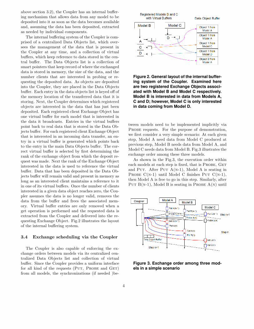
The internal buffering system of the Coupler is com-prised of a centralized Data Objects list, which over-sees the management of the data that is present inthe Coupler at any time, and a collection of virtualbuffers, which keep reference to data stored in the cen-tral buffer. The Data Objects list is a collection ofsmart pointers that keep record of where the exchangeddata is stored in memory, the size of the data, and thenumber clients that are interested in probing or re-questing the deposited data. As objects are depositedinto the Coupler, they are placed in the Data Objectsbuffer. Each entry in the data objects list is keyed off ofthe memory location of the transferred data that it isstoring. Next, the Coupler determines which registeredobjects are interested in the data that has just beendeposited. Each registered client Exchange Object hasone virtual buffer for each model that is interested inthe data it broadcasts. Entries in the virtual bufferspoint back to real data that is stored in the Data Ob-jects buffer. For each registered client Exchange Objectthat is interested in an incoming data transfer, an en-try in a virtual buffer is generated which points backto the entry in the main Data Objects buffer. The cor-rect virtual buffer is selected by first determining therank of the exchange object from which the deposit re-quest was made. Next the rank of the Exchange Objectinterested in the data is used to reference the virtualbuffer. Data that has been deposited in the Data Ob-jects buffer will remain valid and present in memory aslong as an interested client maintains a reference to itin one of its virtual buffers. Once the number of clientsinterested in a given data object reaches zero, the Cou-pler assumes the data is no longer valid, removes thedata from the buffer and frees the associated mem-ory. Virtual buffer entries are only removed when aget operation is performed and the requested data isextracted from the Coupler and delivered into the re-questing Exchange Object. Fig.2 illustrates the layoutof the internal buffering system.
3.4 Exchange scheduling via the Coupler
The Coupler is also capable of enforcing the ex-change orders between models via its centralized cen-tralized Data Objects list and collection of virtualbuffer. Since the Coupler provides a uniform interfacefor all kind of the requests (Put, Probe and Get)from all models, the synchronizations (if needed )be-
Figure 2. General layout of the internal buffer-ing system of the Coupler. Examined here
are two registered Exchange Objects associ-
ated with Model B and Model C respectively.Model B is interested in data from Models A,
C and D; however, Model C is only interestedin data coming from Model D.
tween models need to be implemented implicitly viaProbe requests. For the purpose of demonstration,we first consider a very simple scenario: At each givenstep, Model A need data from Model C produced atprevious step, Model B needs data from Model A, andModel C needs data from Model B. Fig.3 illustrates theexchange order among these three models.
As shown in the Fig.3, the execution order withineach models at each step is fixed, that is Probe, Getand Put. After Put A(n-1), Model A is seating inProbe C(n-1) until Model C finishes Put C(n-1),then Model A is free to go in this step. Similarly, afterPut B(n-1), Model B is seating in Probe A(n) until
Figure 3. Exchange order among three mod-
els in a simple scenario
4

Figure 4. Exchange order among three mod-els in another scenario, in which the execu-
tion orders of Model B and C are not con-
trolled. The changed operations are high-lighted.
Model A finishes Put A(n), and Model C is seating inProbe B(n) until the Model B finishes Put B(n).
Now we consider another scenario: Model B andC are same models with different parameters, bothof them need and change the data from Model A.And the execution order of Model B and C shouldnot be controlled. Fig.4 illustrates the exchange orderamong these three models. In detail, we made followingchanges comparing to Fig.3:
1. Model A: (i) change Probe C(n-1) to ProbeB(n-1) and C(n-1), this operation checks theavailability of B(n-1) and C(n-1); (ii) change GetC(n-1) to Get B(n-1) or C(n-1), this operationget the newer data between B(n-1) or C(n-1);
2. Model B: (i) change Probe A(n) to ProbeA(n) or C(n), this operation check the availabil-ity of either A(n) or C(n), if A(n) is exist, changeits tag to C(n); (ii) change Get A(n) to GetC(n), this operation get the actual data A(n) sincethe tag of A(n) is now C(n);
3. Model C: (i) change Probe B(n) to ProbeA(n) or B(n), this operation check the availabil-ity of either A(n) or B(n), if A(n) is exist, changeits tag to B(n).
4 A case study: Component-based
Ecological Multimodeling Package
In this section, we present an integrated ecosystemmulti-modeling package, Across Trophic Level System
Simulation (ATLSS), to demonstrate the working pro-cedure, the internal data flow and the performanceenhancements of the Coupler. ATLSS has been de-signed to assess the effects on key biota of alternativewater management plans for the regulation of waterflow across the Everglades landscape. The concep-tual model for ATLSS is based on the trophic struc-ture of consumption, who eats who, across the land-scape. Organisms are related energetically as mem-bers of a food chain – a series of organisms that eatone another. (See www.atlss.org for more informa-tion). Although the models within ATLSS use vari-ous modeling approaches to simulate different species,the software structure of each model is similar: eachconsists of three components - the Landscape library,Date library and Model engine. All models withinATLSS use a landscape library to handle the spatialpatterns (maps) of ecosystem components generally de-rived from a geographic information system (GIS). InATLSS, a Date library provides a set of functions formanipulating dates. Those functions include settingand retrieving dates, incrementing and decrementingdates by a specified time interval, taking the differenceof two dates, determining whether one date is laterthan another, and computing the day of year of a givendate. The Model engine of each ATLSS model executesthree phases: initialization, computation and finaliza-tion. In the process of initialization, the model usesconfiguration files to find appropriate input files (eco-logical parameters and geoinformation data). All out-puts are produced in the finalization phase, which in-cludes several geo-information datasets created by theLandscape library. Especially, the integrated simula-tion of two tightly ecological models, Parallel AcrossLandscape Fish model (PALFISH) and Spatially Ex-plicit Species Index model for Wading Bird (SESIWB),is presented.
4.1 The description of two ecological mod-els: PALFISH and SESIWB
PALFISH is a parallel, age-structured populationmodel for freshwater fish functional groups in SouthFlorida. PALFISH includes two main subgroups (smallplanktivorous fish and large piscivorous fish), struc-tured by size. In the complex integrated system ofATLSS, PALFISH is an important link to the higherlevel landscape models, since it provides a food base forseveral wading bird models. The study area for PAL-FISH modeling contains approximately 111,000 land-scape cells, with each cell 500m on a side. Each land-scape cell has two basic types of area: marsh and pond.The fish population simulated by PALFISH is size-
5

structured and is divided into two functional groups:small and large fishes. Both of these groups appearin each of the marsh and pond areas. Each functionalgroup in each area is further divided into several fishcategories according to age, and each age class has 6size classes. The fish population in each cell is sum-marized using the total fish density (or biomass den-sity) within that cell. Each cell, as an element of thelandscape matrices, contains an array of floating-pointnumbers representing individual fish density of variousage classes. The length of the array corresponds tothe number of age classes for that functional group.In PALFISH, spatial and temporal fluctuations in fishpopulations are driven by a number of factors, espe-cially the water level. Fluctuations in water depth,which affect all aspects of the trophic structure in theEverglades area, are provided through an input hy-drology data file for each timestep throughout the ex-ecution of the model. Major concerns associated withPALFISH include its long runtime. The average run-time of PALFISH is around 2-3 hours (using all proces-sors of the 14-CPU 400 MHz Sun Enterprise 4500) fora typical 31-year simulation (See [7, 5, 4] for more in-formation on the parallel implementation and perfor-mance of PALFISH.
SESIWB is one of a family of landscape-based,spatially explicit species index (SESI) models, devel-oped to assess the impact of management scenarioson habitat conditions of different species in SouthFlorida. They provide a relatively easy method of com-paring species responses to environmental conditionsthan more complex approaches such as process mod-els, size-structured population model and individual-based models. Currently, SESIWB produces an indexmap of the annual quality of foraging-conditions forlong-legged wading birds. The stand-alone SESIWBmodel uses topographic and hydrological data pro-vided by the South Florida Water Management Dis-trict (SFWMD) and vegetation data provided by theFlorida Gap Analysis project. The spatial resolution ofthe SFWMD data is 3.2 km by 3.2 km (2 by 2 miles).The outputs of SESIWB include a visual representa-tion of the landscape with color-coded values assignedto each cell and a time series of the mean overall indexattained each year under each hydrologic scenario (see[3] for more information on SESIWB). An integratedsimulation allow us to investigate is whether the ad-dition of complexity in linking the complete ALFISHdynamic to SESIWB produces more accurate projec-tions of wading bird forging condition than SESIWBwould provide alone.
Figure 5. General configuration for the inte-grated simulation
4.2 Computational Platform and software
The computational platforms used in this researchis a Sun Microsystem Enterprise 4500 symmetricmultiprocessor (SMP) configured with 14 400MHzSun Ultra Sparc II processors, which is a part ofthe Scalable Intercampus Research Grid (or SInRG,icl.cs.utk.edu/sinrg) at the University of Tennessee,Knoxville. Each processor has a 16KB instructioncache and a 16KB data cache on chip, plus an 8MBexternal cache for high performance computation. Theentire system has 10 GB main memory and is con-nected via a 3.2 GB/s system bus. The total stor-age capacity of this system is 1.5 Terabytes. An im-plementation of the MPI standard library, LAM-MPI(www.lammpi.org), was selected to support message-passing in the parallel implementations.
4.3 Data exchange between PAL-FISH/SESIWB models
The general configuration for two parallel ecologi-cal models is demonstrated in Fig. 5. The simulationdriver instantiates three components (i.e. PALFISH,SESIWB and the Coupler), and three MPI communica-tors; among these communicators, two are mainly usedfor model simulation, while the other is used to supportdata exchange. There are process overlaps betweenthese communicators (i.e., P0 and P2), which can beused to move data from one communicator (PALFISHor SESIWB domain) to another (Exchange domain).
6

Figure 6. data exchange code segments in
the integrated simulation
4.3.1 Data preparation
PALFISH generates detailed fish densities (in 65 ageclasses, each with 6 size classes for each 500m by 500mspatial cell. The time step of PALFISH is 5 days, pro-ducing over 450 GB for a typical 35-year simulationusing single precision floating-point computation. Onthe other hand, SESIWB utilizes much coarser infor-mation on fish densities, ignoring most size/age dif-ferences, on a 1-day time step. Currently, a binningfunction is used to classify the fish information into8 groups, each having ecological significance to long-legged wading birds. In the PALFISH simulation, allcomputational processors execute the binning functionon their own partial landscape, and then send thosedata to the master processor. The master processor,in turn, push those data (along with timestamps andother meta information) into its own data buffers fortransmission.
4.3.2 Data exchange implementation
Fig.6 illustrates code sections responsible for dataexchange as implemented with the PALFISH andSESIWB code are .
Figure 7. Example model result of SESIWB
and PALFISH. (A) illustrates foraging condi-
tion index value from SESIWB for a singleyear, and makes use of daily results such as
those illustrated in (B). PALFISH output for
a given day is summarized by fish densitymaps as in (B), which is for April 1 of the year
used in (A). Thus, right graphic represents asingle time-slice of results that are combined
to produce left graphic.
4.4 Selected model outputs
Fig. 7 presents model results from the PAL-FISH/SESIWB integrated model. Fig. 7 (A) showsthe output for one year of the SESIWB using a partic-ular hydrologic scenario.The foraging condition indexvalues (ranging from 0 to 1, with 1 indicating opti-mal foraging conditions) provide a method to comparewading bird foraging conditions spatially for any onescenario, as well as between different scenarios for aparticular simulation period. Fig. 7 (B) shows outputfor the ALFISH model, using the same hydrologicalscenario, of the fish densities on April 1 of the samedata year. Data similar to those shown in the Fig.7 (B), produced by PALFISH throughout the breedingseason, are used by the SESIWB to produce the resultsin Fig. 7 (A).
4.5 Performance enhancement via thecoupling component
In this section, we presents results to evaluate theperformance enhancement via the Coupler. We firstdescribe an approach using static exchange routines,which is our first implementation to support the dataexchange between PALFISH and SESIWB.
7
4.6 Static exchange approach
It is also possible to adopt static point-to-pointmessage-passing primitives, provided by MPI, tostrictly synchronize the simulation progress betweenthe two components. [9]. The exchange communica-tion cycle of this simulation requires the deposit trans-fers from PALFISH to be followed by extractions toSESIWB. The cycle repeats until the simulation hascompleted. This approach forces a model to block andwait if the exchange process has not reached the por-tion of the communication cycle with which it inter-acts. The performance of this kind of simulation pro-vide basic information against which we can comparethe performance of the Coupler.
4.7 Performance comparison
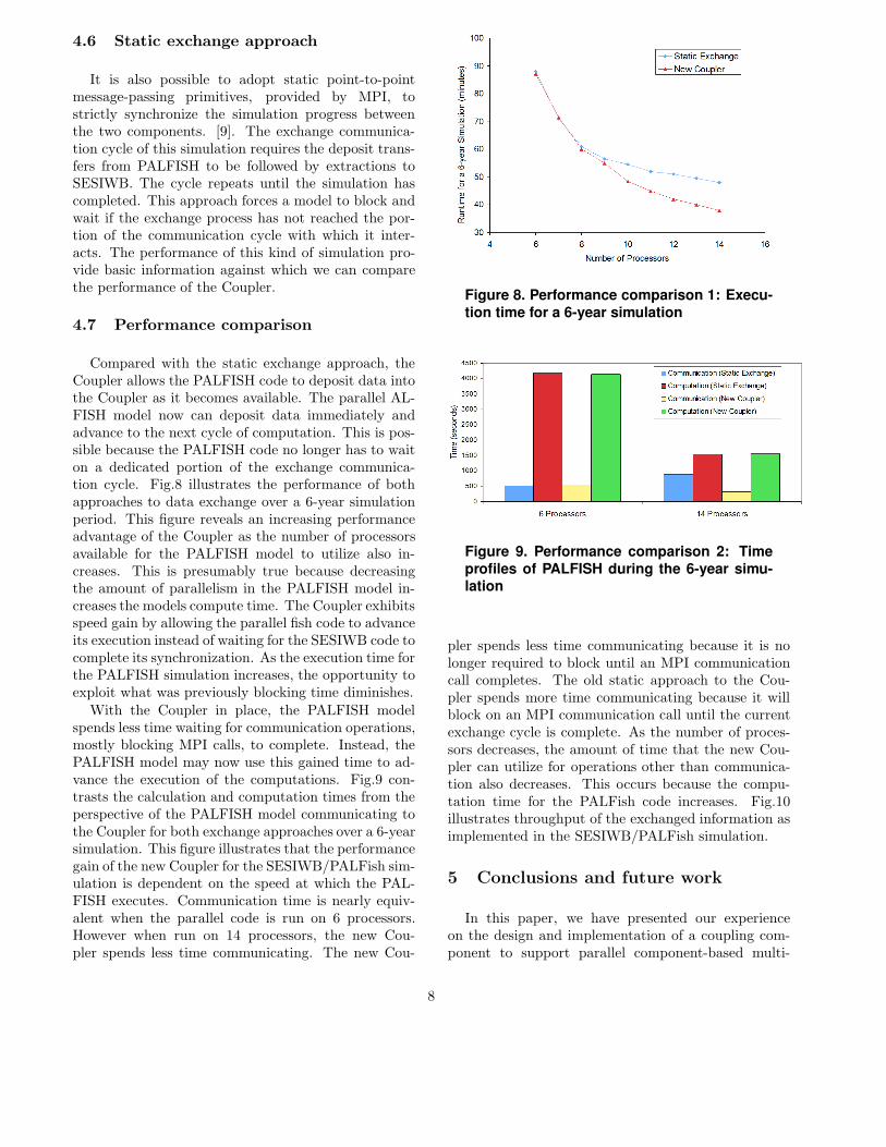
Compared with the static exchange approach, theCoupler allows the PALFISH code to deposit data intothe Coupler as it becomes available. The parallel AL-FISH model now can deposit data immediately andadvance to the next cycle of computation. This is pos-sible because the PALFISH code no longer has to waiton a dedicated portion of the exchange communica-tion cycle. Fig.8 illustrates the performance of bothapproaches to data exchange over a 6-year simulationperiod. This figure reveals an increasing performanceadvantage of the Coupler as the number of processorsavailable for the PALFISH model to utilize also in-creases. This is presumably true because decreasingthe amount of parallelism in the PALFISH model in-creases the models compute time. The Coupler exhibitsspeed gain by allowing the parallel fish code to advanceits execution instead of waiting for the SESIWB code tocomplete its synchronization. As the execution time forthe PALFISH simulation increases, the opportunity toexploit what was previously blocking time diminishes.
With the Coupler in place, the PALFISH modelspends less time waiting for communication operations,mostly blocking MPI calls, to complete. Instead, thePALFISH model may now use this gained time to ad-vance the execution of the computations. Fig.9 con-trasts the calculation and computation times from theperspective of the PALFISH model communicating tothe Coupler for both exchange approaches over a 6-yearsimulation. This figure illustrates that the performancegain of the new Coupler for the SESIWB/PALFish sim-ulation is dependent on the speed at which the PAL-FISH executes. Communication time is nearly equiv-alent when the parallel code is run on 6 processors.However when run on 14 processors, the new Cou-pler spends less time communicating. The new Cou-
Figure 8. Performance comparison 1: Execu-
tion time for a 6-year simulation
Figure 9. Performance comparison 2: Time
profiles of PALFISH during the 6-year simu-lation
pler spends less time communicating because it is nolonger required to block until an MPI communicationcall completes. The old static approach to the Cou-pler spends more time communicating because it willblock on an MPI communication call until the currentexchange cycle is complete. As the number of proces-sors decreases, the amount of time that the new Cou-pler can utilize for operations other than communica-tion also decreases. This occurs because the compu-tation time for the PALFish code increases. Fig.10illustrates throughput of the exchanged information asimplemented in the SESIWB/PALFish simulation.
5 Conclusions and future work
In this paper, we have presented our experienceon the design and implementation of a coupling com-ponent to support parallel component-based multi-
8

Figure 10. Performance comparison 3: Ex-change throughput of the couping compo-
nent
modeling, which, we believe, is an favorable approachto integrate software models from a verity of scien-tific computing research fields and to take advantageof the computing capacity provided by today’s high-performance computers. In this paper, we also use anintegrated ecological modeling, a part of ATLSS forSouth Florida Everglades Ecosystem Restoration, to il-lustrate the internal data flow and to demonstrate theassociated performance enhancement via the couplingcomponent. It is obvious that a better design and im-plementation of the coupling component will not onlyincrease the performance of the integrated multimod-ling simulation, but the key element for scalable large-scale component-based simulations.
Future work includes the development of a man-agement system to monitor and control the data ex-change traffic through the coupling component, so that,user can better ”steer” the integrated simulations. Inthe course of large-scale integrated simulations withmany individual components, it is maybe necessaryto develop a hierarchically-structured coupling compo-nent for better data exchanges and preparations. Ul-timately, affiliated databases may also be needed forbetter management of those exchange data objects. Inaddition, a monitoring system attached to the cou-pling component will act as a useful utility for per-formance monitoring and visualization of component-based integrated simulations. As far as the applicationto ecological multimodel, continuous efforts will focuson further development of data preparation functionsfor integration with other individual model components(such as vegetation model and fire model), a spatialoptimal control component and an Geographic Infor-mation System (GIS) enabled management component[10] as well as affiliated grid service modules [6].
Acknowledgments
This research has been supported by the NationalScience Foundation under grants No.̃IIS-0427471 tothe University of Tennessee. This research used theresources of the Scalable Intracampus Research Grid(SInRG) Project at the University of Tennessee, sup-ported by the National Science Foundation CISE Re-search Infrastructure Award EIA-9972889. For ATLSSmodel development, we appreciate the support of theU.S. Geological Survey, through Cooperative Agree-ment Number 1445-CA09-95-0094 with The Universityof Tennessee.
References
[1] Craig, A., R. Jacob, B. Kauffman, T.Bettge, J. Larson, E. Ong, C. Ding, and H.He, 2005, The new extensible, high-performanceparallel coupler for the Community Climate Sys-tem Model, The International Journal of High Per-formance Computing Applications, Vol. 19, No. 3,pp. 309-328.
[2] Wang, D., M. Berry, L. Gross, 2006, OnParalelization of Spatially-explicit Structured Eco-logical Model for Integrated Ecosystem Modeling,The International Journal of High PerformanceComputing Applications, (accepted) .
[3] J. Curnutt, E. Comiskey, M. Nott and L.Gross, 2000, Landscape-based spatially explicitspecies index models for Everglade restoration,Ecological Applications, Vol. 10,pp.1849-1860
[4] Wang,D., Gross,L., Carr,E., Berry, M.,Design and Implementation of a Parallel FishModel for South Florida, 2004. Proceedingsof the 37th Annual Hawaii International Con-ference on System Sciences (HICSS’04). also athttp://csdl.computer.org/comp/proceedings/hicss/-2004/2056/09/205690282c.pdf
[5] Wang, D., Berry, M., Gross, L., A ParallelStructured Ecological Model for High End SharedMemory Computers, First International Work-shop on OpenMP, 2005, Lecture Notes in Com-puter Science (in press)
[6] Wang,D., Carr,E., Palmer,M., Berry,M.,Gross,L., 2005. A Grid Service Module for Nat-ural Resource Managers, Internet Computing, 9:1.pp.35-41.
9

[7] Immanuel,A., Berry,M, Gross,L.,Palmer,M., Wang,D.,2005. A parallel Im-plementation of ALFISH: CompartmentalizationEffects on Fish Dynamics in the Florida Ever-glades, Simulation Practice and Theory, 13:1,pp.55-76.
[8] Wang, D., Carr, E., Gross, L., Berry, M.,2005, Toward Ecosystem Modeling on ComputingGrids,Computing in Science and Engineering, 9:1,pp44-52.
[9] Wang, D., Carr, E., Comsikey, J., Gross,L., Berry, M., 2005, A Parallel Simualtion Mod-eling Framework for Integrated Ecosystem Model-ing,IEEE Transaction on Parallel and DistributedSystems, (in review).
[10] Wang, D., Carr, E., Comsikey, J., Gross,L., Berry, M., 2005, A GIS-enabled Distrib-uted Simulation Framework for High performanceEcosystem Modeling, ESRI International UserConference, June 1-5, 2006, (in review).
10