On design and modelling of a 10 MW medium speed drivetrain ... · Gear design: ISO 6336-2, 3, 6...
21
EERA DeepWind'19, Trondheim, 16 - 18 January 2019 On design and modelling of a 10 MW medium speed drivetrain for bottom fixed offshore wind turbines Shuaishuai Wang, Amir R. Nejad, Torgeir Moan Department of Marine Technology Norwegian University of Science and Technology January 16, 2019
Transcript of On design and modelling of a 10 MW medium speed drivetrain ... · Gear design: ISO 6336-2, 3, 6...
EERA DeepWind'19, Trondheim, 16 - 18 January 2019
On design and modelling of a 10 MW
medium speed drivetrain for bottom
fixed offshore wind turbines
Shuaishuai Wang,
Amir R. Nejad, Torgeir Moan
Department of Marine Technology
Norwegian University of Science and Technology
January 16, 2019
2
Outline
Introduction
Methodology
Drivetrain design
Drivetrain modelling
Model comparison
Concluding remarks
3
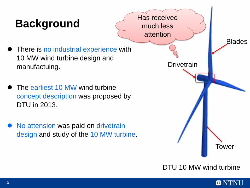
Background
DTU 10 MW wind turbine
Blades
Drivetrain
Tower
Has received
much less
attention
There is no industrial experience with
10 MW wind turbine design and
manufactuing.
The earliest 10 MW wind turbine
concept description was proposed by
DTU in 2013.
No attension was paid on drivetrain
design and study of the 10 MW turbine.
4
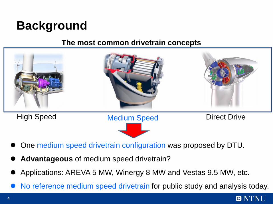
Background
High Speed Medium Speed Direct Drive
The most common drivetrain concepts
One medium speed drivetrain configuration was proposed by DTU.
Advantageous of medium speed drivetrain?
Applications: AREVA 5 MW, Winergy 8 MW and Vestas 9.5 MW, etc.
No reference medium speed drivetrain for public study and analysis today.
5
Motivation
To provide a baseline medium speed drivetrain for
DTU 10 MW RWT.
The baseline model could be used as a reference
model for multi-megawatt scale offshore wind turbines.
Objective
To establish a detailed drivetrain numerical model for
dynamic and reliability analysis.
To provide all modelling parameters to support public
researh studies.
6
Outline
Introduction
Methodology
Drivetrain design
Drivetrain modelling
Model comparison
Concluding remarks
7
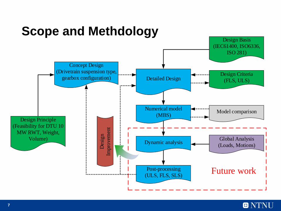
Numerical model
(MBS)
Detailed Design
Dynamic analysis
Post-processing
(ULS, FLS, SLS)
Design Criteria
(FLS, ULS)
Design Basis
(IEC61400, ISO6336,
ISO 281)
Model comparison
Global Analysis
(Loads, Motions)
Concept Design
(Drivetrain suspension type,
gearbox configuration)
Desi
gn
Impro
vem
ent
Design Principle
(Feasibility for DTU 10
MW RWT, Weight,
Volume)
Future work
Scope and Methdology
8
Outline
Introduction
Methodology
Drivetrain design
Drivetrain modelling
Model comparison
Concluding remarks
9
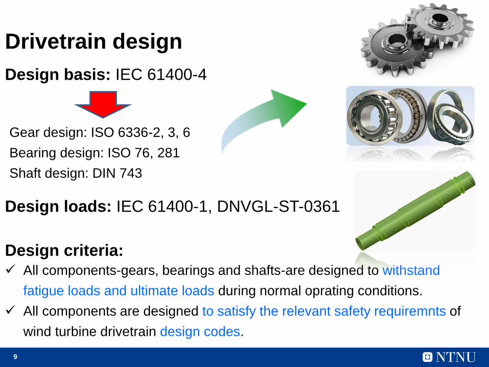
Drivetrain design
Design basis: IEC 61400-4
Gear design: ISO 6336-2, 3, 6
Bearing design: ISO 76, 281
Shaft design: DIN 743
Design loads: IEC 61400-1, DNVGL-ST-0361
Design criteria: All components-gears, bearings and shafts-are designed to withstand
fatigue loads and ultimate loads during normal oprating conditions.
All components are designed to satisfy the relevant safety requiremnts of
wind turbine drivetrain design codes.
10
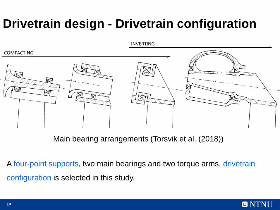
Drivetrain design - Drivetrain configuration
Main bearing arrangements (Torsvik et al. (2018))
A four-point supports, two main bearings and two torque arms, drivetrain
configuration is selected in this study.
11
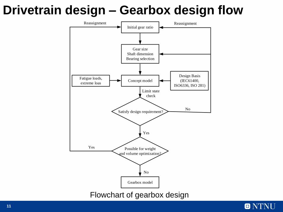
Drivetrain design – Gearbox design flowInitial gear ratio
Gear size
Shaft dimension
Bearing selection
Concept modelFatigue loads,
extreme loas
Design Basis
(IEC61400,
ISO6336, ISO 281)
Limit state
check
Satisfy design requirement?No
Reassignment
Yes
Possible for weight
and volume optimization?
Reassignment
Yes
No
Gearbox model
Flowchart of gearbox design
12
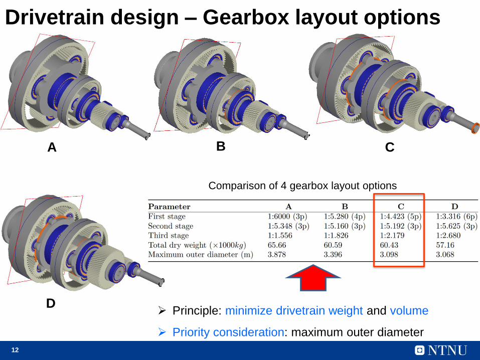
Drivetrain design – Gearbox layout options
Comparison of 4 gearbox layout options
A B C
D Principle: minimize drivetrain weight and volume
Priority consideration: maximum outer diameter
13
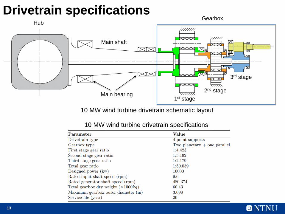
Drivetrain specificationsHub
Main shaft
Gearbox
1st stage
2nd stage
3rd stage
Main bearing
10 MW wind turbine drivetrain specifications
10 MW wind turbine drivetrain schematic layout

14
Outline
Introduction
Methodology
Drivetrain design
Drivetrain modelling
Model comparison
Concluding remarks
15
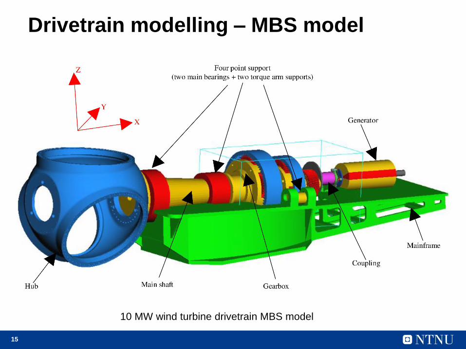
Drivetrain modelling – MBS model
10 MW wind turbine drivetrain MBS model
16
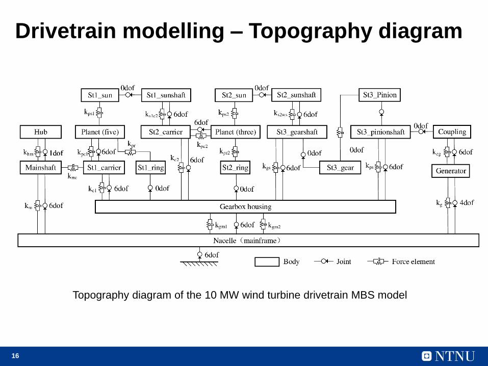
Drivetrain modelling – Topography diagram
Topography diagram of the 10 MW wind turbine drivetrain MBS model
17
Outline
Introduction
Methodology
Drivetrain design
Drivetrain modelling
Model comparison
Concluding remarks
18
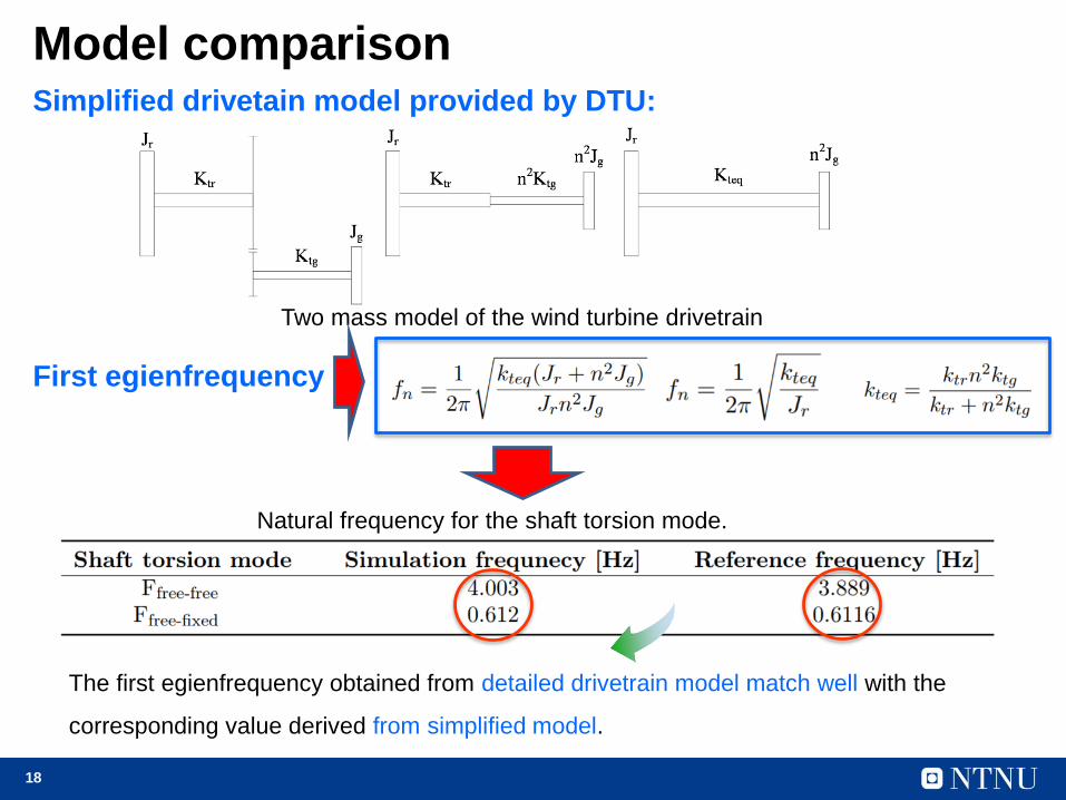
Model comparison
Two mass model of the wind turbine drivetrain
Simplified drivetain model provided by DTU:
Natural frequency for the shaft torsion mode.
First egienfrequency
The first egienfrequency obtained from detailed drivetrain model match well with the
corresponding value derived from simplified model.

19
Outline
Introduction
Methodology
Drivetrain design
Drivetrain modelling
Model comparison
Concluding remarks
20
Concluding remarks
A four-point supports drivetrain configuration and a two planetary
stages + one parallel stage gearbox strucutre is designed for DTU 10
MW wind turbine.
Four gearbox layout options are provided and compared and one
optimized option is finally selected with compromised consideration of
volume, weight and load sharing performance principles.
A high fidelity numerical drivetain model is developed using MBS
method.
Model comparison is conducted, and the rationality of the developed
drivetrain model is initially verified.
21
Thanks