
ON DEMAND BANDWIDTH ALLOCATION USING PMP MODE FOR WIMAX...
126
ON DEMAND BANDWIDTH ALLOCATION USING PMP MODE FOR WIMAX NETWORK SUN ZHEN TAO (WGA060048) FACULTY OF COMPUTER SCIENCE & INFORMATION TECHNOLOGY UNIVERSITY OF MALAYA KUALA LUMPUR MAY 2010
Transcript of ON DEMAND BANDWIDTH ALLOCATION USING PMP MODE FOR WIMAX...

ON DEMAND BANDWIDTH ALLOCATION USING PMP MODE FOR
WIMAX NETWORK
SUN ZHEN TAO (WGA060048)
FACULTY OF COMPUTER SCIENCE &
INFORMATION TECHNOLOGY UNIVERSITY OF MALAYA
KUALA LUMPUR
MAY 2010

ON DEMAND BANDWIDTH ALLOCATION USING PMP MODE FOR
WIMAX NETWORK
SUN ZHEN TAO
DISSERTATION SUBMITTED IN FULFILLMENT OF THE
REQUIREMENTS FOR THE DEGREE OF MASTER OF COMPUTER SCIENCE
FACULTY OF COMPUTER SCIENCE &
INFORMATION TECHNOLOGY UNIVERSITY OF MALAYA
KUALA LUMPUR
MAY 2010

III
UNIVERSITI of MALAYA ORIGINAL LITERARY WORK DECLARATION
Name of Candidate: Sun ZhenTao (I.C/Passport No: G32245576) Registration/Matric No: WGA060048 Name of Degree: MASTER OF COMPUTER SCIENCE Title of Project Paper/Research Report/Dissertation/Thesis (“this Work”):
ON DEMAND BANDWIDTH ALLOCATION USING PMP MODE FOR WIMAX NETWORK
Field of Study: DATA COMMUNICATION & COMPUTER NETWORKING
I do solemnly and sincerely declare that:
(1) I am the sole author/writer of this Work; (2) This Work is original; (3) Any use of any work in which copyright exists was done by way of fair
dealing and for permitted purposes and any excerpt or extract from, or reference to or reproduction of any copyright work has been disclosed expressly and sufficiently and the title of the Work and its authorship have been acknowledged in this Work;
(4) I do not have any actual knowledge nor do I ought reasonably to know that the making of this work constitutes an infringement of any copyright work;
(5) I hereby assign all and every rights in the copyright to this Work to the University of Malaya (“UM”), who henceforth shall be owner of the copyright in this Work and that any reproduction or use in any form or by any means whatsoever is prohibited without the written consent of UM having been first had and obtained;
(6) I am fully aware that if in the course of making this Work I have infringed any copyright whether intentionally or otherwise, I may be subject to legal action or any other action as may be determined by UM.
Candidate’s Signature Date: Subscribed and solemnly declared before,
Witness’s Signature Date:
Name: Mr. Abdullah Gani, Designation: Supervisor

IV
Acknowledgements
I would like to express my heart felt appreciation to Mr. Abdullah Gani, my supervisor,
for his continuous encouragement and guidance throughout this research project and for
his invaluable suggestions and contributions on how to conduct the experiment and
presentation of this thesis.
I would like to give my deepest gratitude to Dr. Omar Zakara, Dr. Rosli Salleh and the
members of the laboratory, namely Li Xichun, Qihan, Zuo Yangping and Yang Lina for
their friendship and help throughout my time with them. A special thank goes to Mr.
Mohd Ezuan Bin Amom, Technician of the Department of Computer System and
Technology, who gave me a lot of help; and Zheng Weibo, who is studying in UM now,
who gave me suggestion to finish my thesis.
I wish to thank a long listing of staff members in office of Faculty of Computer Science
and Information Technology for their help and everlasting friendship. I wish to thank all
the friends that I had known while I was studying here in the University of Malaya, for
their companionships. I wish I could list and mention them all here, but I am sure they
are in my thoughts forever.
Nonetheless, my deepest and sincere gratitude also goes to my family members, they
have given me strong support to continue my master study.

V
Abstract
Bandwidth allocation is always an important element in both fixed and wireless
networks. Despite this, IEEE 802.16e-2005 does not propose any bandwidth allocation
algorithm or mechanism to support (Worldwide Interoperability For Microwave Access)
WiMAX network which includes both uplink (UL) and downlink (DL) directions. Thus,
most of the researches are focusing in this area. In order to satisfy the users and multi-
type services flow, the total capacity of WiMAX system must be optimized. In this
thesis, a new bandwidth allocation mechanism for WiMAX network, called On Demand
Bandwidth Allocation (ODBA) is proposed. The proposed mechanism has the
management module in Subscribe Station (SS), for the purpose of on demand
management of UL bandwidth. This includes UL bandwidth allocation and service flow
schedule; and DL bandwidth allocation and service flow scheduling by Base Station
(BS). The model was implemented and evaluated using OMNeT++ simulator and the
results showed that the ODBA mechanism has a great potential to improve Quality of
Service (QoS) of WiMAX system. The performance of ODBA is better than other
algorithm in queuing delay time, scheduled probability and throughput.
Key Word: WiMAX, 802.16e, Downlink, Uplink, Schedule, Bandwidth Allocation, Service Flow.

VI
Table of Contents Acknowledgements………………………………………………………IV
Abstract…………………………………………………………………V
Table of Contents...……………………………………………………VI
List of Figures...………………………………………………………VIII
List of Tables……………………………………………………………IX
List of Abbreviations...……………………………………………….…X Chapter 1: Introduction ....................................................................................1
1.1 Background ........................................................................................................1 1.2 Motivation..........................................................................................................3 1.3 Statement of Problems .......................................................................................5 1.4 Statement of Objectives .....................................................................................6 1.5 Proposed Solution ..............................................................................................8 1.6 Scope..................................................................................................................9 1.7 Thesis Layout ...................................................................................................10
Chapter 2 WiMAX Overview ..........................................................................12
2.1 IEEE 802.16e-2005 Standard Overview..........................................................12 2.2 Introduction WiMAX Network Technology.....................................................14
2.2.1 WiMAX System.....................................................................................14 2.2.2 WiMAX Key Technology......................................................................17 2.2.3 WiMAX Application..............................................................................19
2.3 Physical Layer Description .............................................................................20 2.3.1 Physical Layer Features .........................................................................21 2.3.2 OFDM/OFDMA Feature........................................................................22 2.3.3 TDD Features ........................................................................................24
2.4 MAC Layer Description..................................................................................27 2.4.1 IEEE 802.16e-2005 MAC Layer Character ...........................................27 2.4.2 Quality of Service (QoS) Support ..........................................................29 2.4.3 MAC layer scheduling mechanism .......................................................31
2.5 Related Research.............................................................................................33 Chapter 3 Requirement of Bandwidth Allocation..........................................41
3.1 Generic concepts of bandwidth allocation ........................................................41 3.2 Bandwidth Allocation Techniques....................................................................43 3.3 Classical Algorithm Review .............................................................................48 3.4 Comparison of the Related Research ................................................................51 3.5 Conclusion ........................................................................................................53
Chapter 4 Model Design....................................................................................54
4.1 Bandwidth Allocation Model Requirements.....................................................54
VII
4.1.1 Ranging ..................................................................................................55 4.1.2 Service Flow Management of WiMAX System ....................................56 4.1.3 QoS Parameters Class ............................................................................58
4.2 Model Characteristics .......................................................................................60 4.3 Model Integration..............................................................................................62 4.4 Conclusion ........................................................................................................66
Chapter 5 Simulation.........................................................................................67
5.1 Test-Bed Tools ..................................................................................................67
5.1.1 OMNeT++ Module ...............................................................................68 5.1.2 NED Language.......................................................................................69 5.1.3 OMNeT++ Simulation Programs...........................................................70
5.2 Simulation ........................................................................................................71 5.2.1 Test-Bed Design.....................................................................................71 5.2.2 WiMAX Simulation Process..................................................................74 5.2.3 Simulation Data Design .........................................................................78
5.3 Performance Metrics .........................................................................................80 Chapter 6 Data Analysis and Discussion .........................................................83
6.1 Introduction.......................................................................................................83 6.2 Scheduled Probability (SP) ...............................................................................84
6.2.1 UL Service Flow Scheduled Probability (SP)........................................85 6.2.2 Comparison of UL Scheduled Probability (SP) .....................................86 6.2.3 DL Service Flow Scheduled Probability (SP)........................................87 6.2.4 Comparison of DL Scheduled Probability (SP) .....................................88
6.3 Queuing Delay Time.........................................................................................90 6.3.1 Different Service Flow Queuing Delay Time ........................................90 6.3.2 Comparison of ODBA And Others Scheduling Algorithm ...................91
6.4 Throughput........................................................................................................93 6.4.1 Peak Throughput ....................................................................................93 6.4.2 Average Throughput ..............................................................................98
Summary .................................................................................................................99 Chapter 7 Conclusion ......................................................................................100
7.1 Evaluation on Our Research Objective Achievement.....................................100 7.2 Significance and Contribution ........................................................................101 7.3 Advantages and Disadvantages.......................................................................102
7.3.1 Advantages...........................................................................................103 7.3.2 Disadvantages ......................................................................................103
7.4 Proposed Future Works...................................................................................103 7.5 Conclusion ......................................................................................................104
Appendix A:.......................................................................................................106 Appendix B:.......................................................................................................107 Appendix C:.......................................................................................................112 References..........................................................................................................113

VIII
List of Figures
2.1 WiMAX Network Infrastructure ....................................................15 2.2 WiMAX OFDMA Frame Structure ................................................25 2.3 IEEE 802.16e MAC Structure..........................................................28 3.1 OFDMA Sub-Carrier Structure .......................................................42 4.1 Dynamic Service Flow Addition request by BS or SS.....................57 4.2 WiMAX System Simple Communication Process...........................60 4.3 WiMAX BS Structure of ODBA .....................................................63 4.4 WiMAX SS Structure of ODBA......................................................64 5.1 Submodules and Parent Module Connection ...................................68 5.2 Simple and Compound models ........................................................69 5.3 Simulation Building and Running Process ......................................71 5.4 Topology of PMP Mode WiMAX Simulation .................................72 5.5 Topology of BS Module...................................................................73 5.6 Topology of bsMAC Module ...........................................................73 5.7 Topology of SS Module ...................................................................74 5.8 Topology of ssMAC Module ...........................................................74 5.9 OMNeT++ Simulator (*.vec) File .................................................. 80 5.10 OMNeT++ Off-line Tool Plove........................................................81 5.11 Simulation Inspector Content...........................................................82 5.12 Simulation Snapshot File Content....................................................82 6.1 UL Service Flow SP With ODBA....................................................85 6.2 Comparison SP of UL Direction With ODBA And Without............86 6.3 DL Service Flow SP With ODBA....................................................88 6.4 Comparison of DL SP With ODBA and Without.............................89 6.5 Different Service Flow Queuing Delay Time With ODBA .............90
6.6 Average Queuing Delay Time of Different SF With ODBA ...........91 6.7 Compared ODBA And Others Alogorithm .....................................92
6.8 ODBA Uplink Throughput ..............................................................93 6.9 ODBA Downlink Throughput..........................................................94
6.10 DL/UL Peak Throughput With Different DL/UL Ratio...................95 6.11 DL Peak Throughput Performance ..................................................96
6.12 UL Peak Throughput Performance ..................................................96 6.13 Average Throughput of Different Algorithm ...................................98

IX
List of Tables
2.1 Basic Characteristics of IEEE 802.16-2004 and IEEE 802.16e.......13 2.2 WiMAX Network PHY Layer Key Features ...................................22 2.3 Parameters of OFDM and OFDMA.................................................24 2.4 WiMAX Service Flow and Quality of Service ...............................31 3.1 SOFDMA Key Physical Parameters ................................................44 3.2 WiMAX Support Adaptive Modulation and Coding .......................45 3.3 WiMAX Mainly Parameters For Performance ................................46 3.4 Optimized WiMAX System Performance ......................................47 3.5 Related Research Algorithm (Scheme) Comparison .......................52 4.1 Different ranging Coded and Function ............................................56 4.2 A Service Flow QoS Parameters Class Relation..............................59
5.1 Simulation Data Value......................................................................79 5.2 Parameters of Different Service Flow..............................................80

X
List of Abbreviations 16QAM 16 Quadrature Amplitude Modulation 64QAM 64 Quadrature Amplitude Modulation ABAS Adaptive Bandwidth Allcoation Scheme AC Admission Control ACK Acknowledge AIS Air Interface Standard AMC Adaptive Modulation and Coding ASR Adaptive Split Ratio ATM Asynchronous Transfer Mode BE Best Effort BER Bit Error Rate BPSK Binary Phase Shift keying BS Base Station BM Bandwidth Management CDMA Coding Division Multiple Accessing CP Cyclic Prefix CPS Common Part Sub-layer CQICH Channel Quality Information Channel CS Service-Specific Convergence Sub-layer DCD Downlink Channel Description DL Downlink EDF Earlist Deadline First ertPS External Real-Time Polling Service FBSS Fast Base Station Switching FCH Frame Control header FDD Frequency Division Duplex FEC Forward Error Correction FFT Fast Fourier Transform HAD Half Duplex Allocation HARQ Hybird Automatic Retransmitted reQuest HO Hand Over HRN Highest Response ratio Next HUF Highest Urgency first LDP Later Deadline Preemption LMA Location Area Management MAC Media Access Control MAN Metropolitan Area Network MDHO Macro Diversity Hand Over MIMO Multi-IN Multi-Out MMPP Markov Modulated Poisson Process MPLS Multi-Protocol label Switching NLOS Non Line of Sight nrtPS Non-Real Time Polling Service ODBA On Demand Bandwidth Allocation OFDM Orthogonal Frequency Division Multiplexing OFDMA Orthogonal Frequency Division Multiple Access PDA Personal Digital Assistant

XI
PDFPQ Preemptive Deficit Fair Priority Queue PDU Protocol Data Unit PER Packet Error Rate PHY Physical PMP Point to Multi-Point QoS Quality of Service QPSK Quadrature Phase Shift Keying RR Round Robin RRMF Round Robin with Multiple Feed back RTG Receive/Transmit Transition Gaps rtPS Real-Time Polling Service SDU Service Data Unit SDUs Signal Distribution Units SF Service Flow SFM Service Flow Management SINR Signal-to-Interference and Noise Ratio SOFDMA Scalable Orthogonal Frequency Division Multiply Access SP Scheduled Probability SS Subscribe Station SSL Security Sub-layer TDD Time Division Duplex TDMA Time division Multiple Access TTG Transmit/Receive Transition Gaps UBAR Uplink Bandwidth Allocation and Recovery UCD Uplink Channel Description UGS Unsolicited Grant Service UL Uplink ULBM Uplink Bandwidth Management VLAN Virtual Local Area Network WiFi Wireless Fidelity WiMAX Worldwide Interoperability for Microwave Access
Chapter 1: Introduction
1
CHAPTER 1
Introduction
1.1 Background The aim of this thesis is to address the bandwidth allocation problem in the (Worldwide
Interoperability for Microwave Access) WiMAX network based on IEEE 802.16e-2005.
The WiMAX radio technology is developed based on wireless transmission platform.
This technology replaces the broadband cable networks and it supports mobile
broadband wireless access. The main advantage of WiMAX network is its capability of
providing high-speed broadband wireless connectivity at low cost.
The initial development of WiMAX is based on the IEEE 802.16-2004 standard
broadband wireless technology, with the objective to reunify the fixed wireless access
air interface. With the advanced development, the second generation of WiMAX is
developed, based on IEEE 802.16e-2005, aiming to support the mobile standards and
mobile station users. However, it encounters the lack of support from past studies.
The WiMAX technology developed based on IEEE 802.16e-2005, is capable of
providing network access to buildings through the external antennas which are
connected to radio base stations. The frequency bandwidth coverage is within the range
from 2 to 66 GHz. This technology operates in two operational modes, defined by the
MAC layer - Point to Multi-point (PMP) and Mesh Mode.
PMP is a centralized architecture where all the traffics between Subscriber Station (SS)
and base station, are controlled by a Base Station (BS). As compared to PMP, Mesh
Chapter 1: Introduction
2
Mode operates where traffic can be routed directly between SS and SS or between SS
and BS. PMP mode mainly applies in WiMAX, where all the data traffics are controlled
by the operating BS.
Traffic direction is used to distinguish two types of data channels: uplink (UL) channel
where the data is sent from the SS to the BS, and downlink (DL) channel where the
burst data is sent from BS to all SS. In both modes, MAC layer is designed to support
quality of service (QoS) in order to enhance the performance parameters in terms of
bandwidth utilization, latency, jitter and reliability to the end users. Besides that strong
QoS is also supported through classification of different service flows and through UL
scheduling for fixed-size real-time service flows.
The five types of service classes defined are: Unsolicited Grant Service (UGS), real-
time Polling Service (rtPS), external real-time Polling Service (ertPS), non-real-time
Polling Service (nrtPS) and Best Effort (BE). The first three classes are used for real-
time fixed-size and non-fixed packet size.
WiMAX can be utilized to implement the last ‘mile’ function for the wireless network.
There are abundance of studies about the efficiency bandwidth utility and its
improvement in recent years. There are also many studies on the implementation of the
WiMAX wireless network support mobile station. However, there is still lack of
research carried out in regards to the bandwidth allocation based on MAC layer of BS
and SS.
Even though some algorithms about various data stream mode and sharing resources of
wireless bandwidth in WiMAX network are available, but there is still lack of research

Chapter 1: Introduction
3
on multiple service flow access control and bandwidth allocation for WiMAX network.
IEEE 802.16e-2005 standard does not suggest any algorithm or mechanism based on
both of these important elements.
1.2 Motivation Bandwidth allocation is always an important element in both fixed and wireless network.
Despite this, IEEE 802.16e-2005 does not have a bandwidth allocation algorithm or
mechanism for supporting WiMAX network presently. Thus, most of the research
initiatives are focusing in this area.
A good algorithm or mechanism is essential to meet the WiMAX QoS demand. The
design must take into consideration the adaptive MAC and physical layer, and translate
the bandwidth of request to appropriate slots number to meet the bandwidth demand
which can guarantee QoS for every SS. Besides, the requirement of the service class
must also be satisfied for the requirements of QoS parameters, such as minimum
reserved rate, priority and maximum latency. The allocation algorithm and mechanism
should serve the service fairly to avoid the starvation of low priority service classes.
Quality-of-Service (QoS) poses as a problem in bandwidth allocation research. IEEE
802.16e-2005 standard defines a relatively complete QoS mechanism in MAC layer, but
it does not provide a guaranteed QoS for wireless resource allocation and demands,
under the multi-user and high upload bandwidth environment. Hence, the problems of
meeting and guaranteeing WiMAX QoS for different users, different uplink and
downlink services need to be solved as well.
Chapter 1: Introduction
4
Guaranteeing QoS of WiMAX network has become a challenging problem due to
satisfying the requirements of different users for different services flow for bandwidth
allocation. IEEE 802.16e-2005 developer is providing different types of service to
guarantee the QoS, but it does not give a specified algorithm or mechanism which can
guarantee the bandwidth allocation for high bandwidth transmission, high capacity,
more service requirement, in consideration of the background of users.
With the rapid development of Internet, the services of multimedia data communication
offered to the consumer market needs to be improved tremendously. As the density of
data (data throughput and coverage) is at a sustained growth rate, the fixed broadband
wireless network access system performance and scalability have become a major
concern.
In order to meet the demand of the rapid growth rate of both users and services required
numbers, the total capacity (including the number of users, data rate and coverage) of
the WiMAX system must be optimal and is able to be extended on-demand.
The physical layer of IEEE 802.16e-2005 provides a number of optimization techniques
and MAC layer contributes to a large amount of bandwidth allocation and QoS rules,
but there are still some issues requiring further research and improvement.
Chapter 1: Introduction
5
1.3 Statement of Problems
In WiMAX network, SS generates bandwidth request message according to its QoS to
the BS. BS utilizes the request-response mechanism for bandwidth allocation. As BS
collects each bandwidth request from the SS through TDD (Time Division Duplex)
method, based on the specified stage of usable bandwidth resource allocation for each
SS, bandwidth resources can be used efficiently in the wireless network environment.
Besides efficiency, flexibility of the resource allocation is also crucial to meet the burst
service flow and required capacity. In order to satisfy the users and multi-type services,
the total capacity of WiMAX system (including subscribers, data rate of support and
coverage) must be optimal and the good coverage of network is required to support new
connections.
IEEE 802.16e-2005 standard provides many optimization techniques of WiMAX
system, however, it does not outline a good mechanism for both system throughput and
different service flow fairness. Bandwidth limitation is one of the main problems which
is limiting the network expandability, due to the usage of many broadband wireless
access systems in a limited bandwidth network, causing resource starvation. A further
study is required on how to utilize the bandwidth resource efficiently, to improve the
throughput and fairness for WiMAX system.
As a background to the technology, currently, WiMAX network supports five types of
service flow: UGS, rtPS, nrtPS, BE and ertPS. The different type service flows are
utilized to meet the demand of various applications and to enhance the network quality
requirements. Both BS and SS of WiMAX, support different treatment of bandwidth
request for various data flow. As the BS periodically polling each SS, and provides data

Chapter 1: Introduction
6
flow service to the corresponding UGS, ertPS and rtPS, all these three type of service
flows will drop out of the bandwidth competition process. However, nrtPS and BE are
allowed to participate in the competition. When BS does not have enough bandwidth,
the nrtPS and BE service will gain bandwidth resource automatically through the
competition.
Another problem in the WiMAX network is due to the (Media Access Control) MAC.
The details of scheduling and threshold management in MAC layer are
incomprehensive, which will restrict the increase in system capacity and network
expansion. As WiMAX MAC layer is facing to the connection layer, the data flows of
the MS include inner non demand connections, mapping connections, and correlation
connections with Service Flow (SF).
IEEE 802.16e-2005 standard does not offer an algorithm or mechanism for bandwidth
allocation and scheduling strategy such as access control, resources reserve, flow
control and group scheduling. These factors have formed as issues for the developers to
resolve. The IEEE 802.16e-2005 standard does not suggest the methodology of
scheduling the network resources to meet different request effectively, and also the
suitable bandwidth utilization to achieve the WiMAX construction requirements.
1.4 Statement of Objectives This thesis aims to implement an on demand bandwidth allocation mechanism by
focusing on the MAC layer for WiMAX network. In this thesis, the bandwidth
allocation process of WiMAX PMP mode is investigated, the application of bandwidth
request in different service flows will also be studied.

Chapter 1: Introduction
7
Whenever there are changes of available bandwidth due to many configuration
parameters, the performance between the BS and Subscriber Stations (SSs) will differ.
In order to solve this issue, this dissertation will cover a proposal of bandwidth
allocation, which is a new, accurate and on demand mechanism.
The objectives of the research are stated as follows:
1) To study the basic concept and characteristics of WiMAX network, and WiMAX
system physical layer and MAC layer features. This can build up a strong basic
knowledge for implementing bandwidth allocation method in WiMAX network.
2) To study bandwidth allocation algorithm and mechanism. Through studying the
existing algorithm and mechanism, the advantages of the mechanism and
algorithm for bandwidth allocation will be realized. This can build up a strong
sense in the bandwidth allocation technology.
3) To study the design requirements of a new bandwidth allocation model. Through
comparison of the related research, and according to the characteristics of
WiMAX system, a clear idea for design of the new bandwidth allocation
mechanism can be generated.
4) To design a new mechanism model for the on demand bandwidth allocation. A
new mechanism which has on demand bandwidth allocation strategy for the
WiMAX network will be designed and developed.
5) To evaluate the model and test the mechanism by OMNeT++ simulation tools. The
mechanism model will be evaluated based on its simulation result, and its
contribution will still be discussed. Based on the findings, the advantages and
disadvantages of the new mechanism can be identified.

Chapter 1: Introduction
8
1.5 Proposed Solution
Based on the analysis of different service flows in different QoS demands, an On
Demand Bandwidth Allocation (ODBA) is proposed. The ODBA consists of a new
mechanism for bandwidth allocation of WiMAX network. The ODBA mechanism will
be developed in accordance to the different link direction, which adopts different
scheduling scheme. Three strategies are proposed in the mechanism to improve the QoS
and fairness of WiMAX.
Firstly, in BS, it will decrease the power usage and resource wastage by sending
response message. As SS, it will decrease the UL bandwidth wastage by SS sending
different service flow bandwidth request message. This is achieved by adopting the
classification bandwidth management strategy. For all of the service flows, the UL
bandwidth request is allocated by SS, while the DL bandwidth is allocated by BS. The
BS allocates sub-carriers for DL/UL, based on the DL/UL total used bandwidth
proportion. This can definitely improve the sub-carriers utilization fairness. With this
strategy, the different SS fairness of bandwidth utilization can be improved as well.
The second strategy is by using the classified scheduling scheme to improve QoS of
WiMAX. With this, the UL service flows are scheduled by SS, while the DL service
flows are scheduled by BS. The objective of this strategy is to improve the efficiency,
so that the BS does not need to perform scheduling and bandwidth allocation and SS
does not require send bandwidth request message to BS for nrtPS and BE service flow
again. The result of this strategy shows that the bandwidth utilization is more efficient
and improved, and it prevents the potential starvation of lower priority service flow. It
avoids the interference of both nrtPS and BE bandwidth request, participating in the
competition, which can greatly improve the fairness of different service flow.

Chapter 1: Introduction
9
The last strategy is by utilizing dynamic adjust modulation and coding based on
different service flow and channel quality. The adoption of this strategy is accordance
with the HARQ probability in selecting the Adaptive Modulation and Coding (AMC)
state. This can improve the throughput of WiMAX, and increase the ratio of data
transmission.
With the ODBA mechanism, the interference of different sub-carriers and sub-channels
will be reduced as well. The parameter of multi-service flow fairness will be taken into
consideration while increasing the network throughput. With this new scheme, a
bandwidth allocation mechanism for WiMAX network is achievable.
1.6 Scope This thesis focuses on the selection of bandwidth allocation methodology, which has
higher efficiency and fairness in the MAC layer based on the PMP model in the
WiMAX network. The bandwidth allocation process of the WiMAX PMP mode and the
bandwidth request applying process of different service flows will also be analyzed.
The ODBA mechanism is proposed, mainly based on the bandwidth allocation, by
testing it in the PMP mode of WiMAX network. The methodology adopted for this
research is only used in situation of fixed subscribe users. The brief scopes of this
research are as following:
IEEE802.16e-2005 standard
PMP WiMAX network
Bandwidth Allocation
MAC layer
On Demand Bandwidth Allocation Characteristics

Chapter 1: Introduction
10
1.7 Thesis Layout There are 7 chapters in this thesis, which are organized as the following:
Chapter I: This chapter briefly describes the WiMAX network background, and the
motivation factor in carrying out this research. Some existing problems of the current
bandwidth allocation on the WiMAX network are highlighted. Subsequently, a proposal
of the solution from the research is designed.
Chapter II: WiMAX network overview. This chapter aims to provide substantial
amount of information for the readers to understand the research subject matter, and the
bandwidth allocation problems on WiMAX network are discussed. The problems are
researched according to the past research materials which summarize the disadvantages
of the existing mechanism and algorithm.
Chapter III: This chapter is a continuation from the previous chapter. It analyses in
detail the problems of bandwidth allocation faced by the WiMAX Networks, which will
be clarified in later part of this thesis. We will describe the methodology of our research,
on how to solve the current problem faced in WiMAX system.
Chapter IV: In this chapter, a newly designed model features and scheduling
mechanism will be discussed in details, for the implementation of an on demand
bandwidth allocation mechanism. We will propose a new mechanism ODBA in this
section.
Chapter V: This chapter will introduce the basic concept about OMNeT++, and how to
use OMNeT++ tools to do the simulation. We will configure the simulation
environment to get the result of WiMAX network with the new designed mechanism.

Chapter 1: Introduction
11
It will provide the key data about our simulation and present the performance of our
research metrics.
Chapter VI: This chapter will present the simulation results, using both illustration and
tabulation to show the simulation details results. We will discuss the results of the
simulation with the objective statements and evaluation of the data collected from the
simulation to ascertain the validity. Statistical tools are utilized to output the analysis of
results. Numerous graphs are drawn with complete caption and substantial explanations.
Chapter VII: This chapter summarizes the entire research objective achievement,
which will conclude with what the advantages and disadvantages of the research are.
Future work will be proposed, based on the current research done and results gained.

Chapter 2: WiMAX Overview and Bandwidth Allocation Issues
12
CHAPTER 2
WiMAX Overview
This chapter aims to present substantial amount of materials for research, and to
highlight the issues which are under consideration. The first section introduces an
overview of IEEE 802.16e-2005 standard. The second section will describe an overview
of the WiMAX network technology. The third section will present the architectures and
characteristics of the physical layer which will cover the research areas of this thesis.
The MAC layer features will be discussed in the fourth section, which includes the
requirements of bandwidth allocation algorithm, as well as the mechanism of QoS
support. The last section will present the problems of the existing algorithm or
mechanism for bandwidth allocation in WiMAX network.
2.1 IEEE 802.16e-2005 Standard Overview In the IEEE 802.16-2004 standard, it is specified that OFDM (Orthogonal Frequency
Division Multiplexing) is the only transmission method for NLOS (Non Line Of Sight)
connections. The OFDM signal is made up of many orthogonal carriers, and every
individual carrier is digitally modulated with a relatively slow symbol rate. This method
has distinct advantages in multi-path propagation because more time is required to
transmit a symbol compared to the single carrier method at the same transmission rate.
Adding a guard interval to every symbol ensures that multi-path propagation does not
disrupt radio transmission. The simultaneous and parallel transmission of multiple
symbols also makes it possible to use error correction to reconstruct the contents of
faulty carriers. These characteristics result in a stable connection with very low Bit

Chapter 2: WiMAX Overview and Bandwidth Allocation Issues
13
Error Rate (BER). The (Binary Phase Shift Keying) BPSK, (Quadrature Phase Shift
Keying) QPSK, (16 Quadrature Amplitude Modulation) 16QAM, and (64 Quadrature
Amplitude Modulation) 64QAM modulation modes are used, and the modulation is
adapted to the specific transmission requirements. This makes transmission rates of up
to 75 Mbits per second possible.
The IEEE organization allowed the IEEE 802.16e-2005 amendment to the existing
IEEE 802.16-2004 standard in December 2005. The IEEE 802.16e-2005 standard is a
further development of 802.16-2004, and it is a further expansion of WiMAX in the
frequency range up to 6 GHz with the objective of allowing mobile applications and
even roaming. This standard includes all the features of IEEE 802.16-2004 as well as
additional functionality. The number of carriers can vary over a wide range depending
on permutation zones and FFT (Fast Fourier Transform) base (128, 512, 1024, 2048).
There are about more than 150 WiMAX trials afoot in Europe, Asia, Africa and North
and South America now (Mobile WiMAX –Part I, 2006). Unchallenged, WiMAX
wireless network has proven to be lower cost than fixed cable services. The FCH
(Frame Control Header) content has been shortened and modified for FFT size 128.
This amendment adds the features and attributes to the standard necessary to support
mobility.
Table 2.1:Basic Characteristics of IEEE 802.16-2004 and IEEE 802.16e
Parameters 802.16-2004 802.16e
Frequency Band 2GHz~11GHz 2GHz~11GHz for fixed 2GHz~6GHz for mobile WiMAX
MAC architecture PMP, mesh PMP, mesh Transmission scheme Single carrier Single carrier, Multiple subcarriers
FFT 256 or 2048 128, 512, 1024, 2048 (256) Modulation QPSK, 16 QAM, 64QAM QPSK, 16QM, 64QAM
Multiplexing OFDM OFDMA Application Fixed NLOS Fixed and mobile NLOS
The basic characteristics of the IEEE 802.16-2004 and IEEE 802.16e-2005 standards
are summarized in Table 2.1. These standards support a variety of design options such

Chapter 2: WiMAX Overview and Bandwidth Allocation Issues
14
as Wireless-MAN-SCa which is a single-carrier based physical layer and Wireless-
OFDMA (Orthogonal Frequency Division Multiple Access) which is an OFDMA-based
physical layer. These designs for MAC operation have many choices in architecture,
frequency band and duplex.
2.2 Introduction of WiMAX Network Technology WiMAX system can cater for both fixed wireless and mobile wireless alternatives, as
compared to conventional DSL and cable Internet. It is described in IEEE 802.16-2004
Wireless Metropolitan Area Network (MAN) standard.
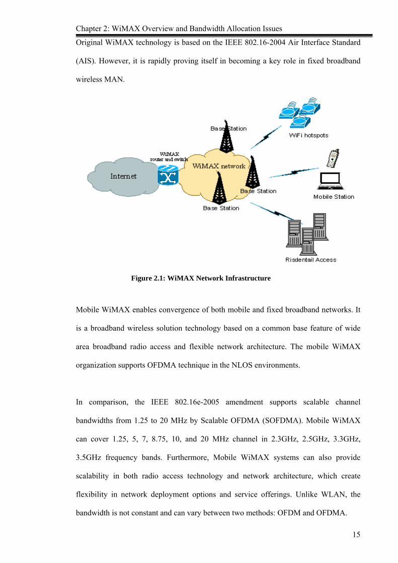
2.2.1 WiMAX System Typically, a WiMAX system consists of two parts: Base Station (BS) and Subscriber
Station (SS) (Figure 2.1). BS consists of outdoor electronics and a tower which can
cover up to 50 km in theory. However, one BS in normal practical consideration can
only cover up to 10 km radius usually. Thus, any wireless node within the coverage area
would be able to access the internet.
SS is a WiMAX receiver, which can either be either a fixed wireless broadband or
mobile broadband terminal, such as residential access, laptop, mobile phone and PDA
(Personal Digital Assistant). A WiMAX BS can be connected to several other BSs using
high speed microwave link which is also known as backhaul. The WiMAX roaming can
be achieved and connections can be maintained on the move, using this link. WiMAX
supports many protocols like ATM (Asynchronous Transfer Mode), IPv4 Ethernet, Ipv6
Ethernet, WiFi (Wireless Fidelity) and VLAN (Virtual Local Area Network), which
makes WiMAX a preferred choice for many types of services from data to voice.
Chapter 2: WiMAX Overview and Bandwidth Allocation Issues
15
Original WiMAX technology is based on the IEEE 802.16-2004 Air Interface Standard
(AIS). However, it is rapidly proving itself in becoming a key role in fixed broadband
wireless MAN.
Figure 2.1: WiMAX Network Infrastructure
Mobile WiMAX enables convergence of both mobile and fixed broadband networks. It
is a broadband wireless solution technology based on a common base feature of wide
area broadband radio access and flexible network architecture. The mobile WiMAX
organization supports OFDMA technique in the NLOS environments.
In comparison, the IEEE 802.16e-2005 amendment supports scalable channel
bandwidths from 1.25 to 20 MHz by Scalable OFDMA (SOFDMA). Mobile WiMAX
can cover 1.25, 5, 7, 8.75, 10, and 20 MHz channel in 2.3GHz, 2.5GHz, 3.3GHz,
3.5GHz frequency bands. Furthermore, Mobile WiMAX systems can also provide
scalability in both radio access technology and network architecture, which create
flexibility in network deployment options and service offerings. Unlike WLAN, the
bandwidth is not constant and can vary between two methods: OFDM and OFDMA.

Chapter 2: WiMAX Overview and Bandwidth Allocation Issues
16
In the normal OFDM mode, 200 carriers are available for data transmission and both
TDD (Time Division Duplex) and FDD (Frequency Division Duplex) methods are used.
In the OFDMA mode, various subscribers can be served simultaneously by assigning
every subscriber a specific carrier group (sub-channelization) that carries the data
intended for the subscriber. The number of carriers is also increased. Mobile WiMAX
network has some salient features support as listed below:
High Speed Data Rates: Mobile WiMAX technology support peak DL data rates
up to 73 Mbps and peak UL data rates up to 28 Mbps per sector in a 10 MHz
channel
Built-in Quality of Service (QoS): IEEE 802.16 MAC architecture support
different service flows map to DiffServ code points or MPLS (Multiprotocol Label
Switching) flow labels, so that it can optimise bandwidth scheduling and resource
allocation.
Support Mobility: WiMAX mobility solution mainly aims to allow service
providers to reach nomadic and mobile customers equipped with portable devices
and allow outdoor roaming across geographical areas of coverage. Services can
provide seamless data handoff as the subscriber moves between different radios
technology, thus, allowing users to satisfy a variety of access needs.
Cost effective: WiMAX network build cost is far less as compared to fixed cable
network.
Additionally, WiMAX has many advantages such as open standard approach and
healthy structure. There are hundreds of companies which have already contributed to
the development of the technology. Many companies have also announced product
plans for this technology, the broad industry participation and worldwide adoption
Chapter 2: WiMAX Overview and Bandwidth Allocation Issues
17
which will ensure cost-efficiency. With its architecture, performance advantages and
wide industry support, the Mobile WiMAX is well-positioned to be a key technology in
the future broadband wireless network.
2.2.2 WiMAX Key Technology
*HARQ
Due to improved spectrum efficiency, HARQ (Hybrid Automatic Retransmitted
request) technology can markedly improve throughput of system. At the same time, the
retransmission benefited from the merger, will help to expand the coverage of the
system. With WiMAX technology usage in such condition, the fading of the wireless
channel is very obvious. The adoption of TCP/IP protocol on an unstable but quality
wireless channel has lower efficiency.
Thereby, WiMAX adopts a HARQ mechanism technology in link layer, to reduce error
information to network layer, and to greatly enhance throughput of system. In
IEEE802.16e-2005 protocol, HARQ is an optional method in MAC. HARQ functions
and related parameters are confirmed and negotiated by SBC message in access or re-
access network processing. HARQ is based on each individual connection, whether or
not the service has HARQ function, with a confirmation by DSA/DSC message.
*AMC
AMC (Adaptive Modulation Coding) is an effective mechanism in WiMAX network. It
can enhance maximum size of throughput in a time-varying channel. Due to WiMAX
supports modulation and forward error correction (FEC) schemes, the AMC algorithm

Chapter 2: WiMAX Overview and Bandwidth Allocation Issues
18
can utilize the highest modulation and coding scheme on each receiver. This is
supported by the Signal-to-Interference and Noise Ratio (SINR) at the subscribe station.
*MIMO
MIMO (Multi-In Multi-Out) is the key technology to the future mobile communications
network. MIMO technology mainly has two forms, namely, spatial multiplexing and
space-time coding. These two forms have been applied in the WiMAX protocol. MIMO
is an optional scheme in WiMAX, combined with adaptive antenna arrays (AAS) and
MIMO technology, can significantly improve system capacity, throughput and spectrum
efficiency, and also enhance the ability to fast fading and extend coverage range, to get
the best performance in different environment.
* Sleep and Idle Mode
IEEE 802.16e-2005 protocol adapts to the characteristics of mobile WiMAX system -
adopt sleep and idle mode. Sleep mode is aimed at reducing energy consumption and
reduce the use of air resources, in serving BS. Sleep mode is a suspend service state in
the pre-specified period in MS. In this state, the MS is at the unavailable state.
Idle mode provides a longer “up” power than Sleep mode for the MS. When entering
the idle mode, MS only receives data of downlink broadcast periodically in discrete
intervals. The difference between idle mode and Sleep mode is that, when in the idle
mode condition, MS is operational or in service connection. Meanwhile, at sleep mode,
the BS is without any connection.
In short, the MS does not require handover when it is through BS, in idle mode; in
reverse, in sleep Mode, MS needs handover, thereby all of the consumptions in both MS
and BS in idle mode are smaller than in sleep mode.

Chapter 2: WiMAX Overview and Bandwidth Allocation Issues
19
*Handover Mode
IEEE 802.16e-2005 standard provides a mandatory switch model, referred to as HO
(handover), namely, hard switch. In addition, it also provides two switch-selectable
modes: MDHO (Macro diversity handover) and FBSS (Fast BS Switching). Switching
can be initiated by MS decision, as well as by BS. During the FBSS, MS only
communicates with anchor BS, while during the MDHO, MS can send and receive data
between different BS.
2.2.3 WiMAX Application
Based on the above characteristics, WiMAX forum provides 5 types of application
definition to WiMAX technology, namely, Fixed, Nomadic, Portable, Simple Mobile
and Full Mobile.
Fixed: In WiMAX network, the most basic service class is fixed access service,
including user access internet, transmission service and WiFi hotspots backhaul.
Nomadic: Nomadic service is the next phase of fixed access network in WiMAX.
Terminals can access to a network from different places; during each session
connection, the user terminal can only access a network by station method; while
accessing two different networks, the data transmitted will not be retained. Both
nomadic and its subsequent applications support roaming technique, and should
have power management features of terminal.
Portable:Under this environment, terminal can be a seamless handover, and do not
intermit the connection. Portable WiMAX is an extended application based on
nomadic WiMAX. In this phase the terminal can be handover in different BS.
When terminal stops to move, the portable WiMAX application will be in the same

Chapter 2: WiMAX Overview and Bandwidth Allocation Issues
20
state as fixed and nomadic WiMAX. However, when terminal is in switching
handover state, user will have a lesser time frame for service break (less than 2s) or
delay. After the terminal finishes the switching process, the TCP/IP protocol will
automatically update the currently IP address, or re-built IP address.
Simple Mobility: The terminal may move at speeds up to 60 km/h with short
interruptions (no more than 1 second) during handoff. In the process of switching,
packet loss will be controlled within a certain range. In the worst case, TCP / IP
session will not be interrupted, but the application layer service may experience
certain disruption. After the completion of switching, QoS will be at the
reconstruction of the initial level. Simple mobile and full mobile networks need to
support full-sleep mode and idle mode. Mobile Data Services is the major
applications in the mobile environment, which are inclusive of mobile E-mail,
streaming media, video telephony, mobile gaming, mobile VoIP (MVoIP) etc.
Hence, they are the services which occupy the highest radio resources.
Full Mobility: Under this application, WiMAX can support user up to 120km/h
mobility and seamless handoff (less than 50 ms latency and one percent packet
loss). When user does not connect to any network, it will require lower power
consumption.
2.3 Physical Layer Description
The WiMAX physical layer can support high-speed data, video, and multimedia
communications. It is based on the IEEE 802.16-2004 and IEEE 802.16e-2005
standards. Although the two standards are different due to the inherent in their purpose
and applications, but some of the basic constructs are very similar.

Chapter 2: WiMAX Overview and Bandwidth Allocation Issues
21
2.3.1 Physical Layer Features WiMAX Forum according to IEEE802.16e-2005 standard defines the air interface of
WiMAX system in Physical (PHY) layer. WiMAX system can use both Orthogonal
Frequency Division Multi-plexing (OFDM) and Orthogonal Frequency Division Multi-
plexing Access (OFDMA) modulation technology, to effectively provide multi-path
access in Non-Line-of-Sight (NLOS) environment. Thus, WiMAX will choose
appropriate bandwidth at 1.25~20MHz, according to the frequency resource and service
flow demand. WiMAX Physical layer adopt to TDD mode, to choose proportion frame
for Uplink and Downlink direction according to the different service demand.
Mobile WiMAX system is suitable for Adaptive Antenna System (AAS) and Multi-
input Multi-output (MIMO) technique by OFDMA and TDD mode. These mechanisms
are able to increase system capacity and wireless transmission power. WiMAX also
adopts to multiple sub-channel and automatic adaptive modulation technology,
depending on different wireless transmission conditions, to select the optimal sub-
channel and coding modulation methods. Downlink can support QPSK, 16QAM
.64QAM, whereas Uplink can support QPSK, 16QAM, optional 64QAM for guaranteed
transmission QoS and throughput. Otherwise, WiMAX system utilizes Hybrid
Automatic Repeat reQuest (HARQ) scheme to achieve quick response and correction
retransmission error mechanism. WiMAX network PHY layer main technology is
illustrated as follows (Table 2.2):
Table 2.2: WiMAX Network PHY Layer Key Features
Technique Parameter WiMAX Frequency Range (GHz) 2~6 System bandwidth (MHz) 1.25~20 Sub-carriers 128, 512, 1024, 2048(OFDMA) Multi-access mode OFDM/OFDMA Full-duplex mode TDD Modulation mode QPSK, 16QAM, 64QAM Mobility Low speed ( <120km/h) Data rate (Mbit/s) <73 (10M bandwidth)
Chapter 2: WiMAX Overview and Bandwidth Allocation Issues
22
2.3.2 OFDM/OFDMA Feature Orthogonal Frequency Division Multiplexing (OFDM) is a multi-subcarriers
technology. This technology is divided into several orthogonal sub-channels, which
convert the high-speed data information into parallel low-speed sub-data flow,
modulated to each channel for transmission. In receiver end, it can separate the
orthogonal superposition of signal through the relevant technology, however, there is no
interference between sub-channels. As each signal bandwidth of sub-channel is with
less channel bandwidth, so each related channel can be regarded as flatness failure fall,
thereby, can eliminate symbol interference between each channel. These channels can
be equalized easily because the sub-channel bandwidth is only a small part of the whole
channel bandwidth. OFDM system has the following advantages:
Strong ability for Anti-multi-path interference and frequency selective decline;
Low complexity of equilibrium;
High frequency of spectrum utilization efficiency which is nearly doubled than
FDM system. This is very important in the limited spectrum resource of the
wireless network environment;
Low computational complexity, which is suitable for high speed transmission.
However, the OFDM has the distinct disadvantage: vulnerable frequency deflection
influence.
Orthogonal Frequency Division Multiple Access (OFDMA) is a multi-user access
technology based on OFDM. For OFDM systems, the common multiplexing method is
OFDM – TDMA (Time Division Multiple Access). OFDM system allocates all sub-
carriers to one user for each time gap. However for OFDMA system, all sub-carriers are

Chapter 2: WiMAX Overview and Bandwidth Allocation Issues
23
divided into each separate channel, which are composed by several sub –carriers. The
system is able to allocate resources by two dimensions - time gap and sub-channel.
Therefore, the size of distribution resources is much smaller as compared to OFDM-
TDMA, hence, the flexibility will be improved greatly.
Due to the flexibility of OFDMA which is able to allocate sub-carrier to multiple users,
and adjust the system resources allocation according to the quality of channel states, it is
more suitable to be used for frequency selective fading channel. As compared to the
traditional OFDM - TDMA method, OFDMA have the following advantages:
Through the variable FFT sizes, it supports multiple channels bandwidth.
When using OFDMA, possible frequency reuse coefficient is 1.
Higher spectrum efficiency can be allocated in sub-carrier level, with maximum
flexibility.
OFDMA sub-carrier allocation is not a necessary adjacent connect in sub-channel.
As sub-carrier is orthogonal, so it is not necessary for strict control power.
Table 2.3: Parameters of OFDM and OFDMA
Parameter Fixed WiMAX Mobile WiMAX Scalable OFDM-PHY OFDMA-PHY
FFT size 256 128 512 1,024 2,048 Number of used data subcarriers 192 72 360 720 1,440Number of pilot subcarriers 8 12 60 120 240 Number of null/guard band subcarriers 56 44 92 184 368 Cyclic prefix of guard time(Tg/Tb) 1/32,1/16,1/8,1/4 Over sampling rate (Fs/BW) 8/7 28/25 Channel bandwidth(MHz) 3.5 1.25 5 10 20 Subcarrier frequency spacing(KHz) 15.625 10.94 Useful symbol time(ms) 0.064 0.0914 Grard time assuming 1/8(ms) 0.008 0.0114 OFDM symbol duration(ms) 0.072 0.1029 Number of OFDM symbols in 5 ms frame 0.069 0.048

Chapter 2: WiMAX Overview and Bandwidth Allocation Issues
24
2.3.3 TDD Features IEEE 802.16e-2005 Physical layer supports TDD (Time Division Duplex), Full and
Half-Duplex FDD (Frequency Division Duplex) operation. The first release of Mobile
WiMAX certification profiles only include TDD mode. With ongoing releases, FDD
profiles are considered by the WiMAX Forum. Eventhough TDD is not a requirement in
system-wide synchronization, but, it is still the preferred duplexing mode for the
following reasons:
TDD only requires a single channel for both downlink and uplink section, and
providing greater flexibility for adaptation to vary global spectrum allocations.
FDD requires a pair of channels to allocate bandwidth for WiMAX network, which
utilizes more bandwidth resource as compared to TDD.
TDD adjusts downlink and uplink ratio for efficient support asymmetric network,
according to the different conditions and QoS demand of service flow. As reversed,
FDD always has a fixed and general ratio which equal DL and UL bandwidths on
downlink and uplink direction.
TDD enables channel to be more efficient. Furthermore, it has better support of DL
and UL adaptation MIMO and other closed loop advanced antenna technologies.
WiMAX network designs for TDD implementations are less complex and therefore,
incur lower cost. OFDMA frame structure for a Time Division Duplex (TDD) is
designed in a way that each frame can be divided into UL and DL sub-frames
separately, to prevent UL and DL transmission collisions by Transmit/Receive and
Receive/Transmit Transition Gaps (TTG and RTG respectively) in a frame. The
OFDMA frame structure based on TDD is illustrated in Figure 2.2.

Chapter 2: WiMAX Overview and Bandwidth Allocation Issues
25
Figure 2.2: WiMAX OFDMA Frame Structure (Mobile WiMAX Part 1, 2006)
WiMAX OFDMA frame with TDD mode includes some features which can be used for
optimal WiMAX system operation as stated below:
Preamble: The preamble is located in the first OFDMA symbol of the UL and DL
frame. In the preamble symbol, it is structurally to include two types of preamble-
long preamble for DL sub-frame and short preamble for UL sub-frame. Long
preamble consists of two symbols. The first symbol which appears once every four
sub-carriers and the second symbol appear once in every two sub-carriers. Short
preamble consists of one symbol only which appears once in every two sub-carriers.
If DL sub-frame transmits multiple data burst, then the middle symbol which
between each burst data, will still be a short preamble. The preamble is used for two
reasons:
♦ It is the start frame of every link for synchronous and channel estimation
between transmitter and receiver.
♦ Preamble carriers number to be used for indication which one of the three
segments of the zone is used. There are 3 segments in preamble carrier - 0, 1, and

Chapter 2: WiMAX Overview and Bandwidth Allocation Issues
26
2. Segment 0 means that carrier 0, 3, 6 … to be used, Segment 1 means that
carriers 1, 4, 7 … to be used, Segment 2 indicates that carriers 2, 5, 8 … are to be
used.
Frame Control Header (FCH): The FCH follows the long preamble. It consists of
one symbol, and provides the frame configuration information, such as usable sub-
channels, MAP message coding scheme and some other transmission parameters.
Every segment must contain a frame control header (FCH) field which is QPSK
modulation and two OFDMA symbols long.
DL Bursts: DL Bursts contains MAC PDU (Protocol Data Unit) and some radio
messages, such as the DL - MAP, UL - MAP, DCD (Downlink Channel
Description), UCD (Uplink Channel Description). A complete PDU should be used
by MAC header of 48 bits, Payload of MAC and cyclic redundancy check CRC
component.
DL-MAP and UL-MAP: The MAP - both DL and UL, provides sub-channel
allocation and other control information. The DL-MAP is transmitted in every
segment, and it contains at least one FCH. The UL-MAP is transmitted by the first
DL burst and it contains information about the location of the UL burst.
UL Ranging: The UL sub-frame includes preamble and UL PDU information, for
example, ranging message. The UL ranging process is based on the SS, send request
message to BS for perform closed-loop time, frequency, and power adjustment as
well as bandwidth requests.
Uplink ACK (Acknowledge): It feedbacks Down Link HARQ (Hybrid Automatic
Repeat reQuest) acknowledgement

Chapter 2: WiMAX Overview and Bandwidth Allocation Issues
27
UL CQICH: The UL CQICH (Channel Quality Information Channel) is allocated to
SS for feedback channel state information. CQICH_ID with SS is a one-to-one
relationship, in order for BS to identify which CQICH to be allocated to the specific
SS
2.4 MAC Layer Description WiMAX MAC protocol supports PMP and mesh network deployment, it provides a
standard service independent interface to the PHY Layer, and each SS creates more
connections upon entering the network. The MAC layer performs link adaptation and
HARQ (Hybird Automatic Retransmitted reQuest) and AMC (Adaptive Modulation and
Coding) functions to maintain the target PER (Packet error rate). It also handles network
entry for MSs that enter and leave the internet, and standard tasks associated with
protocol data unit (PDU) creation. The MAC layer supports asynchronous transfer mode
(ATM) cell and packet based network layers.
2.4.1 IEEE 802.16e-2005 MAC Layer Character In IEEE 802.16e-2005 MAC system (Figure 2.3), it illustrates the connections and data
services flow to transmit various control signal and user data between the BS and MS.
At one end, the system utilizes the service flow to provide the QoS parameters
(including rate and delay difference.) for different quality requirements, in order to
provide better service. At the other end, the MAC layer utilizes the connecting service
to realize the resource management. During the connections, the system realizes the
transmission, through the correlation between service flow and network connection for
the upper and downward service requirements and MAC layer.

Chapter 2: WiMAX Overview and Bandwidth Allocation Issues
28
Figure 2.3: IEEE 802.16e MAC Structure
In order to provide efficient channel access control mechanism, the MAC layer is
defined by IEEE 802.16e-2005 protocol for control mechanisms, mainly includes
service, access control part convergence, ranging, link scheduling, and optional
automatic retransmission mechanism. IEEE 802.16e-2005 MAC layer is divided into
three sub-layers from high to low:
CS (Service—Specific Convergence Sub-layer) Located at the top of the MAC
CPS. The MAC SAP obtains service provided by MAC CPS and it provides services for
the upper layer by CS SAP. It provides the following functions:
Gain PDU (Protocol Data Unit) from upper layer
To classify the upper PDU and to the corresponding MAC layer connection
According to the classified result to specified upper PDU operating (such as
PHS head compression)
Will be sent CS PDU to the relevant MAC SAP
Received CS PDU by peer entities sent

Chapter 2: WiMAX Overview and Bandwidth Allocation Issues
29
For received peer entities CS PDU to unzip and reconstruction package head.
CPS (Common Part Sub-layer) provides MAC layer core functions, such as
system access、initialization、bandwidth allocation or request、connection、and keep
or release etc.
SSL (Security Sub-layer) is an independent safety sub-layer which provides
certification, key exchange and encryption.
The IEEE802.16-2004 standard was developed from the outset for the delivery of
broadband services including voice, data, and video. The MAC layer is based on the
time-proven DOCSIS standard and can support burst data traffic with high peak rate
demand. Simultaneously, it also supports streaming video and latency-sensitive voice
traffic over the same channel. The resource allocated to one terminal by the MAC
scheduler can vary from a single time slot to the entire frame, thus providing a very
large dynamic range of throughput to a specific user terminal at any given time.
Furthermore, since the resource allocation information is conveyed in the MAP
messages at the beginning of each frame, the scheduler can effectively change the
resource allocation on a frame-by-frame basis to adapt to the burst nature of the traffic.
2.4.2 Quality of Service (QoS) Support
Mobile WiMAX MAC (Media Access Control) layer can provide service QoS demand
via vary data service flows. As Mobile WiMAX network has fast air interface,
flexibility resource allocation mechanism, and asymmetric capability of both Downlink
and Uplink, it can well support QoS requirements of broad data services. Prior to the
data transmission, firstly, Base Station and Subscriber Station need to establish a

Chapter 2: WiMAX Overview and Bandwidth Allocation Issues
30
connection between the peer MACs which is a unidirectional logical link. It performs
ordering and scheduling of the packet which will be transmitted on the outbound MAC
interface, according to the QoS parameters. Thus, it can provide exact service flow
control over the air interface. Both DL and UL data service flows are based on QoS
demand, thus MAC messages can manage the different data service flow dynamically.
Mobile WiMAX supports vary data services flow with different QoS requirements. In
order to have the best controlled bandwidth allocation of the mobile WiMAX network,
IEEE 802.16e-2005 standard defines the following 5 types of service flow:
UGS (Unsolicited Grant Service)
Unsolicited Grant Service (UGS) supports real-time connection with fixed length, such
as voice over internet protocol (VoIP) with no silence inhibition. The QoS parameters
include tolerated jitter, minimum reserved traffic rate and maximum latency.
rtPS (Real-Time Polling Service)
Real-Time Polling Service (rtPS) supports variable length real-time connections, like
Moving Picture Experts Group (MPEG) video. The QoS parameters include maximum
latency, minimum reserved traffic rate, maximum sustained traffic rate and traffic
priority.
ertPS (Extended Real-Time Polling Services)
Extended Real-Time Polling Services (ertPS) supports real-time connection with
combined UGS and rtPS characters, like voice over internet protocol (VoIP) with mute
inhibition. The QoS parameters include maximum latency, tolerated jitter, minimum
reserved traffic rate, maximum sustained traffic rate and traffic priority.
nrtPS ( Non-Real Time Polling Service)

Chapter 2: WiMAX Overview and Bandwidth Allocation Issues
31
Non-Real-Time Polling Service (nrtPS) supports non real-time connection, like File
Transfer Protocol (FTP). The QoS parameters include minimum reserved traffic rate,
maximum sustained traffic rate and traffic priority.
BE (Best Effort)
Best Effort (BE) service for best effort traffic, like Hypertext Transfer Protocol (Email).
No demand of QoS necessary.
The different SF has the different QoS demand. This is summarized in Table 2.4.
Table 2.4 : WiMAX Service Flow and Quality of Service
Service Flow types QoS Demand Parameters UGS
(Unsolicited Grant Service) Tolerated Jitter Minimum Reserved Rate
ertPS (Extended Real-Time Polling Services)
Tolerated Jitter Maximum Latency Minimum Reserved Rate Maximum Sustained Rate Traffic Priority
rtPS (Real-Time Polling Service)
Maximum Latency Minimum Reserved Rate Maximum Sustained Rate Traffic Priority
nrtPS ( Non-Real Time Polling Service)
Minimum Reserved Rate Maximum Sustained Rate Traffic Priority
BE (Best Effort) Minimum Reserved Rate Traffic Priority
2.4.3 MAC layer scheduling mechanism The BS depends on the uplink and downlink scheduler to achieve the scheduling of
efficient data flow services. Based on the Uplink upward direction, Uplink scheduler
controls the Uplink wireless channel distribution and utilization, and it decides which
wireless bandwidth is for the users. In Downlink direction, Downlink scheduler controls
the Downlink bandwidth allocation of resources utilization, and decides the way to
distribute and limit the resources. This shall also satisfy the different service flows and
demand of QoS.

Chapter 2: WiMAX Overview and Bandwidth Allocation Issues
32
Uplink scheduler
IEEE standard 802.16e-2005 MAC layer Uplink wireless resource allocation is mainly
used for all of MS Uplink wireless resource allocation management within the scope of
the BS. Periodic radio UL-MAP is utilized to control all the uplink-channel access of
the terminal. Uplink wireless resource allocation consists of two processes: measure
distribution range and Uplink scheduling process. The process of measure distribution
range allocates suitable bandwidth range to competing windows in uplink bandwidth
sources; the Uplink scheduling process will allocate the bandwidth reasonably to the
registered users.
Uplink Wireless resource is allocated by the specific Uplink upward scheduling
algorithm of the Uplink scheduler. The uplink scheduler mechanism quality is the key
factor in the Uplink channel utilization. The QoS parameters and channel quality
parameters of scheduling are connected using the Uplink scheduling algorithm
reasonable distribution and transmission bandwidth for each terminal. The distribution
results through UL-MAP will notify all radio terminals. This is performed by the Uplink
scheduler according to various terminal bandwidth requests. The terminal scheduler will
grant Uplink bandwidth to each service flow correspondence Uplink connection to
ensure the quality of service.
Downlink scheduler
The BS Downlink scheduler performs downward data queue through CS (Convergence
Sub-layer) maintenance. According to IEEE 802.16-2004 agreement, the classification
of the PDUs (Protocol Data Units) of up-layer will be transmitted according to a set of
matching CS layer rules. The SDUs (Signal Distribution Units) at the MAC layer

Chapter 2: WiMAX Overview and Bandwidth Allocation Issues
33
mapping will be generated to the corresponding transmit connection, and will add to the
corresponding data queue. The Downlink scheduler will combine the current system
total bandwidth capacity to allocate the bandwidth for each downlink service flow based
on the service flow parameters and the data queue.
The downlink scheduler wireless resources allocation is based on the frequency domain,
time domain and the users. In time domain, the downlink scheduler needs to have
choice when sending the data. While in frequency domain, the downlink scheduler
needs to choose to send data in the choice of channels. In the user domain, downlink
scheduler bandwidth allocation must satisfy the requirements of the service flow QoS.
In our research, the scheduling algorithm does not take into consideration of the
dynamic selection channels in frequency domain, and the channels that have similar
transmission power. In order to simplify the scheduling algorithm, the Downlink
scheduler will only emphasis on the time gap, and choice of the service flow required to
decide the volume of data transmitted for this service flow. The scheduler downlink is
designed under certain challenges: under the condition of the fairness to satisfy service
flow quality of the QoS requirements, and to improve the system throughput. In
addition, it needs to take into consideration of the process scheduling in a frame for
completion, to achieve simplicity and efficiency.
2.5 Related Research Numerous researches have been conducted with the objective to improve the
performance of WiMAX bandwidth allocation. Some proposed research works will be
discussed in this section.
Chapter 2: WiMAX Overview and Bandwidth Allocation Issues
34
Garssian model and Chernoff bound method are applied for aggregated traffic in large
network (Wang, et al., 2006). The objective of this research is to analyze the upper
bound blocking probability above the packet level for all types of traffic in WiMAX
network. The result shows that this methodology can be used as approximate blocking
probability when network is large. Furthermore, it is more efficient in numerical
computing, as compared to Erlang B formula. The lack of efficiency in Erlang B
formula is due to the fact that the connection/ burst duration for fractal traffic (rtPS,
nrtPS and BE) is not an exponential distribution. Hence, the Markov Chain method can
not be used to analyze the performance. Another important result shows that Garrsian
model is not suitable to be used for network bandwidth allocation.
Another research carried out is the adoption of UBAR (Uplink Bandwidth Allocation
and Recovery) protocol (Chou & Lin, 2007). In this protocol, the proportional fair
scheme is employed to utilize the bandwidth efficiently. It also adopts the timeout-based
UL-MAP retransmission scheme with uplink bandwidth reallocation algorithms to
simultaneously solve three bandwidth waste problems. UBAR has the following
beneficial characteristics:
a) UBAR adopts the differentiated admission control scheme which higher priority
service flows can reserve larger guaranteed transmission rate ratios than lower
priority ones.
b) UBAR provides isolation among admitted service flows while utilizing bandwidth
resources as efficiently as possible.
c) UBAR adopts a timeout-based UL-MAP retransmission scheme to ensure that the
idling UL-subframe problem will never occur.
d) UBAR employs the bandwidth recovery scheme. Once a polled SS does not
respond to the UL-MAP or stops sending padding MPDUs, the unused channel

Chapter 2: WiMAX Overview and Bandwidth Allocation Issues
35
time may be recovered or shared with other non-transmitted over-demanded SS.
In the research conducted by (Andrew & Claudio, 2007), sufficient conditions are
generated for a set of scheduled grants, which are to be allocated, in order to prevent the
overlapping of transmission of each half-duplex SS with its reception. From the
research, a grant allocation algorithm – Half-Duplex Allocation (HDA), is proposed, to
ensure a consistent and feasible grant allocation and sufficient conditions are met. The
research shows that from the application of HAD, the delay of real-time and non real-
time interactive traffic for both SS and half-duplex, and full-duplex SS are almost
equivalent.
Another critical research by Chiang & Liao (2007) states the adaptive bandwidth
allocation and uplink and downlink channels in Time Division Duplex (TDD), based on
IEEE 802.16 protocol. An Adaptive Bandwidth Allocation Scheme (ABAS) is proposed,
which adjusts the bandwidth ratio according to the current traffic profile. This is
important due to the fact that negative impact of improper bandwidth ratio on the
performance of TCP. The results show that through the application of ABAS, the
aggregate throughput is higher.
In (Patrick, 2007), conducted a research on the power and bandwidth allocation
problems for the downlink. This research studies the power allocation to a vary channel
continuously, however, it is necessary to provide the bandwidth allocation in discrete
units (number of sub-carriers). A practical algorithm is proposed which is able to
increase the efficiency by varying the resources in the bandwidth dimension in addition
to the power dimension.

Chapter 2: WiMAX Overview and Bandwidth Allocation Issues
36
In a research related to QoS management, the Preemptive Deficit Fair Priority Queue
(PDFPQ) scheduling architecture is introduced by Safa & Artail, (2007). This is an
extension of the DFPQ scheduling technique introduced in previous research. Through
PDFPQ, the QoS requirements of real time polling service (rtPS) flow class is enhanced
and the delay and throughput are improved as well.
The first research conducted to evaluate the performance of several packet scheduling
schemes, is carried out by Lin & Chou (2008). The research proposed a new model,
which is able to provide better packet scheduling to various applications. The new RIO
scheduling scheme is best when the system requires the best throughput performance in
this network transport environment, despite its worse throughput in higher bottleneck
link. Another result shows that WFQ can be used to automatically assign suitable
weight for different service flows according to their priority, even though it is not the
best scheduling scheme available.
In a study conducted by Lin & Wu (2008), it was found that the mobile WiMAX
systems developed based on IEEE 802.16e-2005 standard, provide high data rate for the
mobile wireless network. However, the real-time applications are impacted negatively
due to the instability of the long distance and air interferences. This research proposes
the Highest Urgency First (HUF) algorithm which is modulation-aware, while further
satisfying the latency guarantee, service differentiation and fairness.
A Location Area Management (LMA)-based MBS handover is proposed by Lee &
Kwon (2008). Those objectives are to deal with both the bandwidth utilize and service
disruption problems. From the results of the quantifiable analytical model, it shows that

Chapter 2: WiMAX Overview and Bandwidth Allocation Issues
37
this proposed scheme is able to improve the bandwidth efficient multicast delivery with
an insignificant increase of the average service disruption.
Camargo (2008) analyzed the impact caused by overhead on the bandwidth allocation
mechanism of WiMAX networks. The number of SS that can be served by each BS and
the influence of adaptive modulation and coding configuration are discussed in this
research. During the evaluation, time variant physical conditions of the wireless channel
were considered as the physical impairment in the broadband wireless access network
design. The results show that the control messages used and the redundant information
inserted by AMC (in VoIP transmission with background traffic) are affected by the
overhead.
An adaptive channel split ratio of uplink to downlink capacities is researched by Chiang
& Liao (2009). The focus of this research is on BE scheduling service, aiming to
provide efficient service for many existing Internet applications, for example Web
browsing, FTP and P2P file sharing. An Adaptive Split Ratio (ASR) scheme is
developed based on the research and it is able to adjust the downlink to uplink capacity
ratio adaptively according to the current traffic profile, wireless interference and
transport layer parameters. The unique point of the scheme is its capability to cooperate
with the BS scheduler to throttle the TCP source when acknowledgements are
transmitted inconsistently, thus preventing either direction from becoming the
bottleneck. Results show that ASR is capable of generating higher aggregate throughput
and better adapt to network dynamics.
The performance of the different polling mechanisms was evaluated and it was found
that an optimal unicast and contention-based mixed polling mode for nrtPS proposed
Chapter 2: WiMAX Overview and Bandwidth Allocation Issues
38
could allocate the bandwidth more efficiently and better performance can be achieved
(Yin & Pujolle, 2008). Simulation models were used to analyse the performance of
different polling mechanisms. Results show that the all-unicast polling mechanism
performs well in low load conditions but works poorly in high load conditions since it
takes too much bandwidth for unicast polling.
An important research later deadline preemption (LDP) algorithm was carried out by
Liang & Shao (2008). The research results in the development of a new packet
scheduling algorithm for WiMAX systems running time division duplex (TDD) mode.
The performance of the bandwidth and fairness of the proposed algorithm is compared
with other algorithms. Results show that the new algorithm not only outperforms other
algorithms in terms of higher throughput in dynamic bandwidth allocation, but also a
guaranteed QoS support for better fairness.
Liu & Chen (2008), carried out a research on the utilization of contention-free period to
allocate slots for bandwidth request. From this study, a new scheme is proposed, which
is able to lower the delay and improve the QoS performance for ertPS flows as the
number of stations increase. However, this proposal does not have a precise algorithm
to calculate the suitable contention-free period and is only estimated to be half of the
contention period only.
Kim & Yeom (2007), initiated a research, which proposed a new uplink scheduling
scheme for best-effort TCP traffic in WiMAX networks. The unique element of this
proposal is that it does not require any bandwidth request process for allocation. It only
estimates the amount of bandwidth required for a flow based on its current sending rate.
Results show that the proposed scheme is effective to allocate bandwidth for TCP flows.

Chapter 2: WiMAX Overview and Bandwidth Allocation Issues
39
A research has been carried out on the performance of dynamic bandwidth allocation in
broadband wireless networks under dynamic arrival process and channel SNR is
evaluated, using queuing analysis framework (Fathi & Taheri, 2009). The transmission
rate is adjusted adaptively in each frame time according to channel quality using
adaptive modulation and coding rate, with the objective of obtaining multi-user
diversity gain. The arrival process modeled by the Markov Modulated Poisson Process
(MMPP) is considered to be the traffic source. Besides, the QoS parameters are also
evaluated under several allocated bandwidth to a single queue in the case.
The performance of three types of WiMAX connections namely UGS, rtPS and nrtPS
are evaluated in a research by Ghazal & Mokdad (2008). In this study, different levels
of priority and blocking probability are assigned to each class of service. This
evaluation is carried out based on analytical model for evaluating admission control
(AC) for the previous mentioned classes in WiMAX network.
A novel control mechanism has been developed to investigate the bandwidth allocation
problem in relation to the QoS support in a WiMAX environment (Marchese &
Mongelli, 2007). This research is carried out with the presence of heterogenous traffic
trunks.

Chapter 2: WiMAX Overview and Bandwidth Allocation Issues
40
Conclusion:
In the preceding sections, we presented materials of WiMAX networks with the
intention to provide better insights into the subject matters. We first outlined the account
of history and followed by the discussion on architecture, and characteristics. Some
possible applications available within the WiMAX networks were also discussed to
indicate its applicability to the real world. We also provided descriptions of several key
parameters in WiMAX PHY and MAC layer.
At the end of this chapter it has indicated that many researches were carried out on the
scheme, algorithm and mechanism. However, with the rapidly growing and changing
features of WiMAX networks, there are still many challenges that need to be addressed.
For instance, in order to offer better network performance, new scheme or algorithm for
WiMAX network needs to be carried out. This would be our premise in undertaking this
research work.
In the following chapter, we will discuss the basic theoretical framework of bandwidth
allocation, and bandwidth allocation characters.

Chapter 3: Requirement Of Bandwidth Allocation
41
CHAPTER 3
Requirement of Bandwidth Allocation
In the previous chapter, an overview of WiMAX network was presented which
discussed the bandwidth allocation and some challenges faced. In this chapter, the
bandwidth allocation technique will be introduced and elaborated. In this chapter, as
overview of WiMAX network bandwidth allocation will be presented. The first section
presents generic concepts of bandwidth allocation. In the second section, the bandwidth
allocation techniques will be introduced. There are four classical schedule algorithms of
WiMAX bandwidth allocation, and these algorithms will be reviewed in section three.
In section four, the advantages and disadvantages of related past research will be
evaluated. The related past researches include the reviews of some algorithms and
mechanisms, which have been identified in the previous chapter. The algorithms
proposed in the researches claimed to be able to improve the QoS performance of
bandwidth allocation in WiMAX system. A brief conclusion will be given in the last
section of this chapter.
3.1 Generic concepts of bandwidth allocation Bandwidth allocation is based on symbol and channel in WiMAX network. At present,
OFDMA has been widely studied, and has become the main multiple-access scheme of
both downlink and uplink direction in WiMAX.
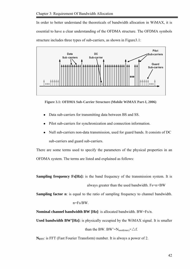
Chapter 3: Requirement Of Bandwidth Allocation
42
In order to better understand the theoreticals of bandwidth allocation in WiMAX, it is
essential to have a clear understanding of the OFDMA structure. The OFDMA symbols
structure includes three types of sub-carriers, as shown in Figure3.1:
Figure 3.1: OFDMA Sub-Carrier Structure (Mobile WiMAX Part-I, 2006)
Data sub-carriers for transmitting data between BS and SS.
Pilot sub-carriers for synchronization and connection information.
Null sub-carriers non-data transmission, used for guard bands. It consists of DC
sub-carriers and guard sub-carriers.
There are some terms used to specify the parameters of the physical properties in an
OFDMA system. The terms are listed and explained as follows:
Sampling frequency Fs[Hz]: is the band frequency of the transmission system. It is
always greater than the used bandwidth. Fs=n×BW
Sampling factor n: is equal to the ratio of sampling frequency to channel bandwidth.
n=Fs/BW.
Nominal channel bandwidth BW [Hz]: is allocated bandwidth. BW=Fs/n.
Used bandwidth BW’[Hz]: is physically occupied by the WiMAX signal. It is smaller
than the BW. BW’=Nused(max)× f.△
NFFT: is FFT (Fast Fourier Transform) number. It is always a power of 2.
Chapter 3: Requirement Of Bandwidth Allocation
43
f:△ is sub-carrier spacing which is the distance between two adjacent physical OFDM
carriers. f=Fs/N△ FFT
Tb: is a valid symbol time.
Tg: is cyclic prefix (CP) time. It is equals guard period ratio/interval G multiply Tb.
Ts: is the complete OFDM symbol time consists of useful symbol time Tb and cyclic
prefix time Tg.
Nused: is used as sub-carriers number for data transmission.
DC sub-carrier: is not used for data transmission.
Pilot carriers: are used to synchronize for the SS to the BS.
3.2 Bandwidth Allocation Techniques According to IEEE 802.16-2004 protocol, OFDM physical layer adopts 256 sub-carriers
and the OFDMA physical layer adopts 2048 sub-carriers. The channel frequency of
these is in the range from 1.25MHz to 20MHz.
The OFDMA physical layer features are modified in IEEE 802.16e-2005 standard,
which now can support four types of different sub-carriers, the numbers separated are:
128 512 1024 and 2048. The common characteristics that distinguish this technology
from the previous are fixed sub-carrier spacing and directly proportional signal
bandwidth and the sub-carrier number. This technology is also called extensible
OFDMA, namely SOFDMA (Scalable OFDMA). By adopting this technique, the
system is flexible in adapting channel bandwidth changes in the mobile environment.
The biggest distinction between SOFDMA and OFDMA is the changes of FFT size
supported. SOFDMA symbol is based on the concept of OFDMA. WiMAX PHY makes
use of TDD mode and it requires system synchronization. However, the sub-carrier
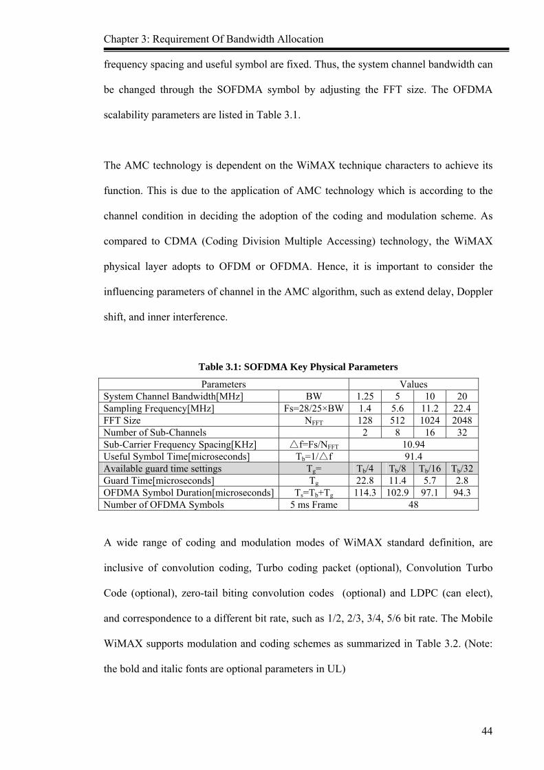
Chapter 3: Requirement Of Bandwidth Allocation
44
frequency spacing and useful symbol are fixed. Thus, the system channel bandwidth can
be changed through the SOFDMA symbol by adjusting the FFT size. The OFDMA
scalability parameters are listed in Table 3.1.
The AMC technology is dependent on the WiMAX technique characters to achieve its
function. This is due to the application of AMC technology which is according to the
channel condition in deciding the adoption of the coding and modulation scheme. As
compared to CDMA (Coding Division Multiple Accessing) technology, the WiMAX
physical layer adopts to OFDM or OFDMA. Hence, it is important to consider the
influencing parameters of channel in the AMC algorithm, such as extend delay, Doppler
shift, and inner interference.
Table 3.1: SOFDMA Key Physical Parameters
Parameters Values System Channel Bandwidth[MHz] BW 1.25 5 10 20 Sampling Frequency[MHz] Fs=28/25×BW 1.4 5.6 11.2 22.4FFT Size NFFT 128 512 1024 2048Number of Sub-Channels 2 8 16 32 Sub-Carrier Frequency Spacing[KHz] f=Fs/N△ FFT 10.94 Useful Symbol Time[microseconds] Tb=1/ f△ 91.4 Available guard time settings Tg= Tb/4 Tb/8 Tb/16 Tb/32Guard Time[microseconds] Tg 22.8 11.4 5.7 2.8 OFDMA Symbol Duration[microseconds] Ts=Tb+Tg 114.3 102.9 97.1 94.3Number of OFDMA Symbols 5 ms Frame 48
A wide range of coding and modulation modes of WiMAX standard definition, are
inclusive of convolution coding, Turbo coding packet (optional), Convolution Turbo
Code (optional), zero-tail biting convolution codes (optional) and LDPC (can elect),
and correspondence to a different bit rate, such as 1/2, 2/3, 3/4, 5/6 bit rate. The Mobile
WiMAX supports modulation and coding schemes as summarized in Table 3.2. (Note:
the bold and italic fonts are optional parameters in UL)

Chapter 3: Requirement Of Bandwidth Allocation
45
Table 3.2: WiMAX Support Adaptive Modulation and Coding
DL UL Modulation QPSK, 16QAM, 64QAM QPSK, 16QAM, 64QAM CC ½, 2/3, 3/4, 5/6 1/2, 2/3, 5/6
CTC 1/2, 2/3, 3/4, 5/6 1/2, 2/3, 5/6 Code Rate Repetition ×2, ×4, ×6 ×2, ×4, ×6
The combinations of system bandwidth and sub-carriers, various code rate and
modulations, and other key parameters as listed in Table 3.3 (Mobile WiMAX-Part I,
2006), provide a good support for WiMAX networking. The optional 64QAM data rates
are highlighted in the Table 3.3, and they include system bandwidth 5MHz and 10MHz,
and main parameters for performance.
WiMAX system is also able to support different zone types for DL and UL directions,
which are described in the following:
DL-PUSC (Downlink Partial Usage of Sub-Channel): This zone must be the first DL
zone type. It only uses groups of sub-channels and does not use all the
logical sub-channels.
DL-OPUSC (Downlink Optional Partial Usage Sub-Channel): is a special form of a
PUSC zone, its description by one bit in the DL_MAP.
DL-FUSC (Downlink Full Usage of Sub-Channel): can distribute all bursts over the
complete frequency range. It does not use any segments.
UL-PUSC (Uplink Partial Usage Sub-Channel): same DL_PUSC.
UL_OPUSC (Uplink Optional Partial Usage Sub-Channel): same DL_OPUSC.
UL_FUSC (Uplink Full Usage Sub-Channel): same DL_FUSC.
An optimized WiMAX system can improve throughput by 20% to 30%, with the
DL/UL useful symbols ratio of 28:9 and 22:15 respectively (Mobile WiMAX Part I,
2006). There are 11 symbols of system in total for a conservative estimation of

Chapter 3: Requirement Of Bandwidth Allocation
46
overhead. For WiMAX network, it is assumed that the WiMAX system is working
based on a TDD mode with a 10 MHz channel bandwidth, SIMO (Single-Input
Multiple-Output) and MIMO (Multiple-Input Multiple-Output) antenna configurations.
The performance of this assumption is summarized in Table 3.4:
Table 3.3: WiMAX Mainly Parameters For Performance
Table 3.4: Optimized WiMAX System Performance
Cases DL: 28 data symbols UL: 9 data symbols
DL: 22 data symbols UL: 15 data symbols
Antenna Link Sector Throughput
Spectral Efficiency
Sector Throughput
Spectral Efficiency
DL 8.8 Mbps 1.19 bps/Hz 6.6 Mbps 1.07 bps/Hz SIMO UL 1.38 Mbps 0.53 bps/Hz 2.20 Mbps 0.57 bps/Hz DL 13.60 Mbps 1.84 bps/Hz 10.63 Mbps 1.73 bps/Hz MIMO UL 1.83 Mbps 0.70 bps/Hz 3.05 Mbps 0.79 bps/Hz

Chapter 3: Requirement Of Bandwidth Allocation
47
Based on IEEE 802.16e-2005 frame structure as discussed in details (in Chapter 2), it is
known that the required spending of the DL direction includes:
- Preamble, FCH (Frame Control Header), DL_MAP and UL_MAP, total about 3
OFDM symbols;
- UL direction required spending include ACK (Acknowledge), CQI (Channel
Quality Indicator) and Ranging, total about 2 OFDM symbols; and
- TTG (Transmit/receive Transition Gap) and RTG (Receive/transmit Transition
Gap) total about use 1 OFDM symbol.
Thus, only one frame is used to transmit useful data information with maximum 44
OFDM symbol. In conclusion, it is possible to obtain the normal WiMAX academic
calculation formula of WiMAX network throughput B as illustrated below:
B = (Nused - NPilots) × Mr × Cr / Ts (1)
Nused refers to used sub-carriers number for data transmission,
NPilots refers to the pilots number used for synchronization for SS to BS,
Mr: is modulation state. (BPSK=1, QPSK=2, 16QAM=4, 64QAM=6)
Cr: is coding rate. (e.g: 1/2, 2/3, 3/4, 5/6)
Mr × Cr: refers to each sub-carrier carries bit in each symbol.
Ts: is overall symbol time.(Ts=Tb+Tg)
Thus, the formula can be changed to:
B = (Nused - NPilots) × Mr × Cr / (Tb+Tg)
= (Nused - NPilots) × Mr × Cr / ((1+CP) × (NFFT/(n×BW)) (2)
BW refers to system bandwidth
CP refers to the available guard time settings parameters (e.g:1/4, 1/8, 1/16, 1/32),

Chapter 3: Requirement Of Bandwidth Allocation
48
n: means sampling factor. This value is set according to the following rules: for channel
bandwidth as 1.25/1.5/2/2.75 MHz integer times, then n = 28/25; for channel bandwidth
is different from the provisions, then n = 8/7.
NFFT: total sub-carriers number. (10 MHz= 1024, 5 MHz = 512)
When both DL and UL have service flow transmission, then DL and UL direction
throughput is RDL and RUL respectively:
BDL = (Nused - NPilots) × Mr × Cr / ((1+CP) × (NFFT/(n×BW)) × (DL/(DL+UL)) (3)
BUL = (Nused - NPilots) × Mr × Cr / ((1+CP) × (NFFT/(n×BW)) × (UL/(DL+UL)) (4)
DL/(DL+UL): means that DL used sub-carriers occupy all data sub-carriers percent
UL/(DL+UL): means that UL used sub-carriers occupy all data sub-carriers percent
3.3 Classical Algorithm Review
According to the wireless packet scheduling strategy, the end-to-end operations must
take into considerations factors like the quality requirements and the priority and latency
of service flow requirements under the condition of the principle for both the throughput
maximization and fairness. Thereby, some famous algorithms will be discussed in the
following section.
RR (Round Robin) Algorithm
RR polling scheduling is introduced to ensure all users within the area have sufficient
time to communicate within the wireless resources, in accordance with the order of a
circular. The users who are nearby the border will get lower throughput, as compared to
the users who are near to the BS. Hence, the QoS for the users is not completely fair.
The algorithm execution is according to the following rules:
i. Every user with a corresponding cached queue, to preach data storage;

Chapter 3: Requirement Of Bandwidth Allocation
49
ii. In scheduling, the non-empty queue in circulation service in the form of data
transmission;
iii. In a queue before receiving services again, all other non-empty queue must have
been served; unless only has a non-empty queue, otherwise a queue may not accept
services continuously;
iv. Scheduling algorithm can transmit more packets at any one time.
RR scheduling from the fair distribution of resources, guarantees all the users to occupy
the same time to communicate, so it not only ensures the long-term equity, but also
ensures the fairness in short-term between different users.
The loop hole of RR algorithm is its inconsideration of QoS for different users of the
specific conditions, which results in lower system throughput.
RRMF (Round Robin with Multiple Feedback) Algorithm
The algorithm sets up queue which is ready for multi-single queue, and it authorizes
them according to different priority, such as gradual grade reduction - the queue 1 has
the highest priority. Every queue has its own schedule algorithm, and each queue
running time is different as well. Hence, it requires scheduling between different queues
and, normally the pre-empt schedule of fixed priority is adopted. When the system is
scheduling packet of the lower priority queue, the higher priority queue will be empty.
In the same circumstances, if there are new packets in the higher queue, the system will
then schedule the priority of the new packets, and place the packets which are stopped
before, at the end of queue.

Chapter 3: Requirement Of Bandwidth Allocation
50
EDF (Earliest Deadline First) Algorithm
The Earliest Deadline First algorithm (EDF) is a very famous real-time scheduling
algorithm. With every new ready condition, the deadline will carry out the assigned
tasks with the required resources. This is performed even though the scheduler is ready
but has not fully processed the choice of the task.
In every incoming new task, the scheduler must immediately calculate the EDF and
create the new sequencing (namely the running task be interrupted) according to the
new task deadline and decides on the new task scheduling. If the new task deadline has
been earlier than the interrupted task, the new task will be executed immediately.
According to the EDF algorithm, the interrupted task will continue to process later.
HRN (Highest Response ratio Next) Algorithm
Highest Response ratio Next (HRN) algorithm is an integration balance of FCFS (First-
Come First-Serve) and SJF (Shortest Job First) algorithms. FCFS algorithm only
considers the waiting time of every service flow, without considering the running time
of the service flow. The SJF algorithm only considers the running time, and it does not
consider the waiting time. Thus, these two scheduling algorithms have a distinguished
disadvantage. In view of this, the development of HRN scheduling strategy is taking
into consideration both service waiting time and estimated running time simultaneously.
The choice service, which has the highest response proportion R, will be the first to be
placed for scheduling. The response proportion R formula is as the following:
R = (W + T) / T = 1+ W/T (5)
T as the service estimate running time, normal it is equal service flow size divide rate.
W as service flow waiting time in admitted service queue.

Chapter 3: Requirement Of Bandwidth Allocation
51
While scheduling service flow, the system will calculate every service flow response
proportion, and schedule the highest R service flow to be sent first. This is to ensure
even if there are some long service flows in admitted service queue, but after the time
and W/T added, the long service flow can get an opportunity for scheduling. This can
avoid the possibility of starvation service flow in WiMAX network
3.4 Comparison of the Related Research
In order to solve the problems of WiMAX bandwidth allocation, many of researches
have been carried out to improve the QoS of WiMAX performance. Some proposed
algorithms or schemes are summarized in Table 3.5. The strengths and weaknesses of
each algorithm or scheme are highligted in the table.
As shown in Chapter 2, the past researches mostly focus on parts of the conditions of
WiMAX network. Some of the researches are to improve the system throughput and
some suggested the methodologies to improve different services fairness. However, all
of the researches do not propose a mechanism or algorithm for on demand bandwidth
allocation on WiMAX network. Hence, a new mechanism model for bandwidth
allocation on WiMAX network will be introduced in the following section.

Chapter 3: Requirement Of Bandwidth Allocation
52
Table 3.5: Related Research Algorithm (Scheme) Comparison
Algorithm (Scheme)
Advantages Disadvantages
Garssian model and Chernoff bound method
To be applied for aggregated traffic in large network. It is more efficient in numerical computing, as compared to Erlang B formula.
It is not suitable to be used for network bandwidth allocation.
UBAR (Uplink Bandwidth Allocation and Recovery) protocol
In this protocol, the proportional fair scheme is employed to utilize the bandwidth efficiently.
UBAR provides isolation among admitted service flows, so it is not a fairness protocol.
Half-Duplex Allocation (HAD) scheme
The delay of real-time and non real-time interactive traffic for both SS and half-duplex, and full-duplex SS are almost equivalent.
It is not an efficient bandwidth allocation scheme, as it generates lower throughput.
Adaptive Bandwidth Allocation Scheme (ABAS)
It adjusts the bandwidth ratio according to the current traffic profile and the aggregate throughput is higher
It does not consider the service flow fairness and causes service starvation
Preemptive Deficit Fair Priority Queue (PDFPQ) scheme
The QoS requirements of real time polling service (rtPS) flow class is enhanced and the delay and throughput are improved as well
Weak fairness. It only considers one type of service flow. It is insufficient for WiMAX network bandwidth allocation.
Highest Urgency First (HUF) algorithm
The algorithm is modulation-aware, while further satisfying the latency guarantee, service differentiation and fairness
The long term service flow perhaps could not be scheduled for long time.
Location Management Area (LMA) scheme
It can improve the bandwidth efficiency and decrease service disruption.
It does not satisfy the nrtPS, BE service delay and bandwidth usage requirements.
Adaptive Split Ratio (ASR) scheme
ASR is capable of generating higher aggregate throughput and it better adapts to network dynamics.
It does not adapt to the impact of cooperative communications on the split ratio determination problems for WiMAX relay networks.
Later Deadline Preemption (LDP), algorithm
The algorithm improves throughput in dynamic bandwidth allocation, and guarantees QoS support for better fairness.
It does not satisfy the rtPS service.

Chapter 3: Requirement Of Bandwidth Allocation
53
3.5 Conclusion This chapter analyzed the problems of bandwidth allocation. In the first section, the
OFDM and OFDMA concepts are introduced, which are inclusive of the OFDMA
symbols structure and the four types of sub-carrier concepts. Some technologies of
bandwidth allocation in WiMAX are studied, analyzed and compared. It was found that
the signal frequency and the sub-carrier number are directly proportional. This
technology called SOFDMA, is able to support FFT changes when the signal bandwidth
is changing. The AMC technology and characters are presented in this section and it is
able to support WiMAX system by adjusting the data transmission rate dynamically
according to the channel quality. The formula of WiMAX system throughput and
DL/UL throughput is introduced. This is followed by the description of four algorithms
which will be used in the new model design for scheduling of different service flow -
RR, RRMF, EDF and HRN (RR or more commonly known as RRMF). Finally, the
advantages and disadvantages of the past researched mechanisms or algorithms are
analyzed and compared.

Chapter 4:Model Design
54
CHAPTER 4
Model Design
This chapter aims to introduce the proposed on demand bandwidth allocation model
with guaranteed QoS on WiMAX network. A new mechanism of ODBA (On Demand
Bandwidth Allocation) will also be introduced as well. The generic concepts and
techniques of bandwidth allocation, and scheduling algorithms and mechanisms in
WiMAX network are discussed. In this chapter, the new model of this research will be
introduced. In the first section, the key features of bandwidth allocation model required,
which include the ranging process, service flow management and QoS parameters are
presented. While in the second section, there are three strategies to be carried out for
designing the new model. The characteristics of the new model in WiMAX system are
highlighted and will be discussed in this section. The integrated new model will be
presented in section three, which includes analysis of three scenarios. Besides, each of
the module functionality and methodology will be introduced in section three. Finally, a
brief conclusion of this chapter will be drawn in section four.
4.1 Bandwidth Allocation Model Requirements
Prior to the introduction of the new model, it is important to ensure a clear
understanding of some of processes and parameters in WiMAX. These elements are the
important requirements of the new model designed.
Chapter 4:Model Design
55
IEEE 802.16-2004 MAC protocol supports QoS by three partitions: first, the initial
service flow and QoS parameters created and configured. Secondly, dynamic
management of service flow, which includes Dynamic Service Addition (DSA),
Dynamic Service Change (DSC) and Dynamic Service Deletion (DSD). Finally, the
classification of MAC protocol data unit (PDU) according to the different service flow
QoS parameters. Otherwise, the different type service flow scheduling according to the
different service flow priority.
4.1.1 Ranging
In WiMAX system, ranging is a method which can determine the distance from BS to
SS or from SS to BS position. OFDMA Physical layer adopt binary phase-shift keying
(BPSK) modulation state to send 144 bits Code Division Multiple Access (CDMA)
code for initial ranging. After BS receives RNG-REQ (Ranging Request) CDMA code,
BS will send RNG-RSP (Ranging Response) and UL-MAP messages to terminal by
broadcast. The UL-MAP messages include CDMA allocation IE for description of the
specified UL channel to send RNG-REQ message by terminal. If SS does not respond
and does not feedback any acknowledgement (ACK) message, then the BS will increase
power to broadcast RNG-RSP until receipt of the ACK message by SS. Subsequently,
the terminal will synchronize with the BS and adjust the frequency time and power
according to the RNG-RSP message content. In initial ranging process, BS will choose
suitable Downlink Interval Usage Codes (DIUCs) according to Carrier Interference and
Noise Ratio (CINR) of DL direction, and suitable Uplink Interval Usage Codes (UIUCs)
according to the CINR of UL direction.
WiMAX ranging process includes 4 types of ranging codes: initial ranging code period
ranging code handover (HO) ranging code and Bandwidth Request (BR) ranging code.

Chapter 4:Model Design
56
The different ranging codes have different functionality, as shown in Table 4.1. Prior to
the SS and BS data transmission, the BS and SS are required to establish logical
connection by initial ranging. Subsequently, while BS and SS data are transmitting, the
WiMAX system requires period ranging for dynamic adaptive signal power between BS
and SS. When an SS moves into another BS zone, SS needs HO ranging to establish a
new connection with the new BS. During the communication between BS and SS, they
need BR ranging for dynamic bandwidth request.
Table 4.1: Different Ranging Coded and Function
Ranging Code Type Function
Initial ranging code Establish connections between BS and SS
Period ranging code BS and SS to keep in contact
HO ranging code Establish connection between SS and new BS.
BR ranging code SS sends bandwidth allocation request to BS.
4.1.2 Service Flow Management of WiMAX System
In MAC layer, the service flow can perform dynamic addition dynamic change and
dynamic deletion. The term ‘dynamic’ means that these operations can only be
processed while BS and SS are communicating, and it unable to be created before
communication. The dynamic service flow can only be created by the BS or SS.
The dynamic service addition request (DSA-REQ) message which are created by the BS
or SS, include a service flow Identifier (SFID) of UL or DL direction, a Connection
Identifier (CID) which is associated with it, and a group QoS parameters of admitted or
activated service flow. The DSA process of UL/DL direction are shown in Figure 4.1,

Chapter 4:Model Design
57
BSSS DSA-REQ
DSA-RSP
DSA-ACK UL Direction
DL Direction
Figure 4.1: Dynamic Service Flow Addition Request by BS or SS
In the UL direction, each connection is characterized by a group of QoS parameters
configured, and it belongs to a single service flow type. After BS receives the DSA-
REQ message from SS, BS will check whether uplink bandwidth resource is still
sufficient. If BS has sufficient bandwidth resource to be allocated to SS, then BS will
feedback the DSA-RSP message to SS. When SS receives the DSA-RSP message from
BS, SS will feedback the DSA-ACK message to BS as acknowledgement of the receipt
of the DSA-RSP message. If the BS receives DSA-ACK message from SS, then BS will
place the SS on the polling list, and allocates the bandwidth to uplink direction for SS.
In reverse, if the DSA-REQ message is created by BS, the DL direction processing is
similar as the UL direction.
The dynamic service change request (DSC-REQ) message which uses SFID to specify
service flow will be changed. The DSC process does not only change the QoS
parameters of specified service flow, but can also affect the addition and deletion or
switchover SFID. The DSC process can change the service flow QoS parameters from
“NULL” to “NON-NULL” or from “NON-NULL” to “NULL”, to achieve either
activated or deactivated service flow.

Chapter 4:Model Design
58
All of the service flow can be deleted by the DSD-REQ (dynamic service deletion
request) message which can be created by either BS or SS. If the service flow is deleted,
all of the related resource will be free up. If the SS basic service flow is already deleted,
the SS must re-register to the BS for transmission. Normally, DSD-REQ uses SFID to
specify the service flow which will be deleted. When the DSD-REQ message is created
by the DSA process, means that the BS did not allocate SFID for this service flow now,
so DSD-REQ message can use service flow refer (SFR) to specify the SF which will be
deleted.
4.1.3 QoS Parameter Class QoS parameter class is a group of parameters gathered which are used to describe a
service flow, such as maximum delay, tolerant Jitter and Minimum Reserved Traffic
Rate. Normally, a service flow includes three classes: preparative QoS parameters
class、admitted QoS parameters class and activated QoS parameters class.
The preparative QoS parameters class is the specified configuring parameters of the
static or dynamic service flow. WiMAX system can check whether the resource
required is satisfied while configuring or creating the service flow. As for the
preparative service flow, the service flows QoS parameters of both admitted and
activated are “empty”.
The admitted QoS parameters Class are parameters which can be satisfied for BS
resource demand. For admitted service flow, BS reserves the resources according to the
service flow QoS parameters, but it is indeed, not a really occupied resource. Otherwise,
the activated service flow QoS parameters is “non-empty”.
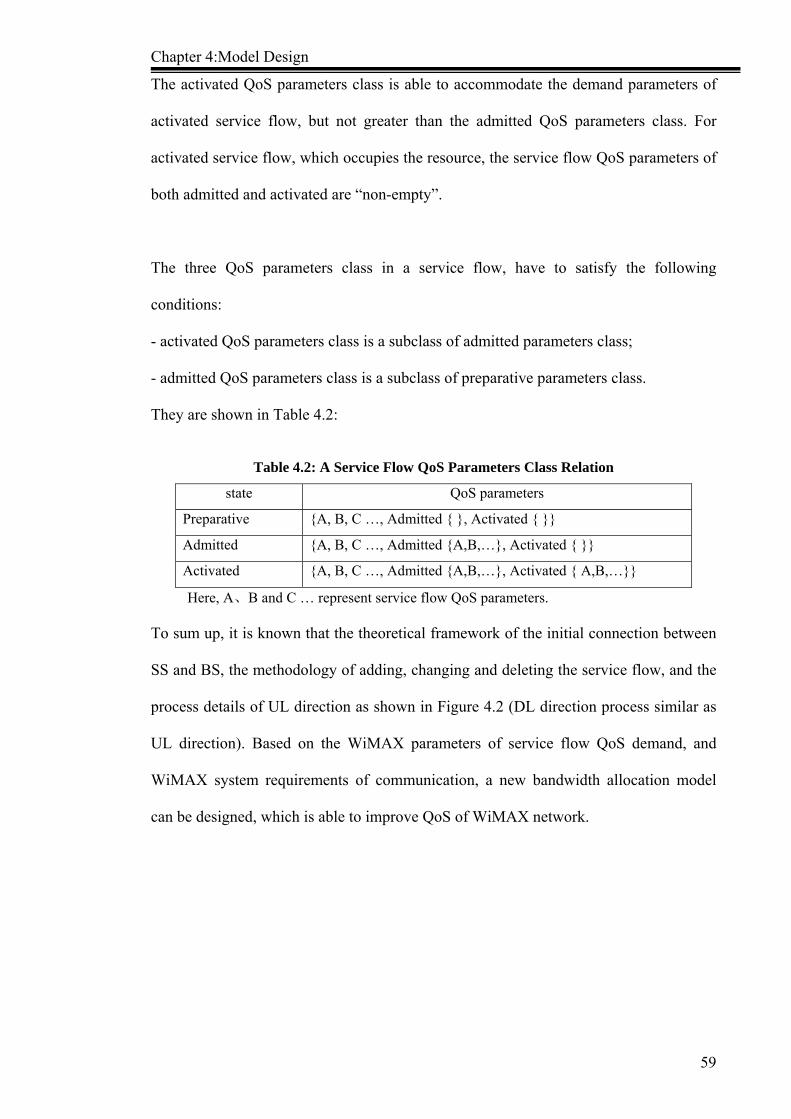
Chapter 4:Model Design
59
The activated QoS parameters class is able to accommodate the demand parameters of
activated service flow, but not greater than the admitted QoS parameters class. For
activated service flow, which occupies the resource, the service flow QoS parameters of
both admitted and activated are “non-empty”.
The three QoS parameters class in a service flow, have to satisfy the following
conditions:
- activated QoS parameters class is a subclass of admitted parameters class;
- admitted QoS parameters class is a subclass of preparative parameters class.
They are shown in Table 4.2:
Table 4.2: A Service Flow QoS Parameters Class Relation
Here, A、B and C … represent service flow QoS parameters.
To sum up, it is known that the theoretical framework of the initial connection between
SS and BS, the methodology of adding, changing and deleting the service flow, and the
process details of UL direction as shown in Figure 4.2 (DL direction process similar as
UL direction). Based on the WiMAX parameters of service flow QoS demand, and
WiMAX system requirements of communication, a new bandwidth allocation model
can be designed, which is able to improve QoS of WiMAX network.
state QoS parameters
Preparative {A, B, C …, Admitted { }, Activated { }}
Admitted {A, B, C …, Admitted {A,B,…}, Activated { }}
Activated {A, B, C …, Admitted {A,B,…}, Activated { A,B,…}}

Chapter 4:Model Design
60
RNG-REQRNG-RSP
REG-REQ
REG-REQ
DSA-REQ
DSA-RSPDSA-ACK
DSC-REQDSC-RSPDSC-ACK
DSD-REQ
DSD-RSP
SS BS
Ranging
Registration
DSA
DSC
DSD
Figure 4.2: WiMAX System Simple Communication Process
4.2 Model Characteristics There are three strategies which will be carried out to design the new model as
discussed in the following section.
♦ Strategy 1: Using Hierarchical Management
In WiMAX system, BS allocates bandwidth resource to UL by SS unit. In DL direction,
BS allocates bandwidth according to the QoS demand of different service flow. The BS
will calculate the total bandwidth of DL/UL requirement respectively. Then admission
control will allocate the sub-carriers for DL/UL used, according to the proportion of
DL/UL required total bandwidth.
This strategy can highlight the characters as follows:
- In UL direction, because bandwidth allocation is by SS unit. The SS does not need to
send every bandwidth request message for every service flow. Thus it can decrease UL
spending of bandwidth resource which by it can only send bandwidth request message

Chapter 4:Model Design
61
occupied. By this way, it can decrease delay time and Jitter, and increase different user
fairness.
♦ Strategy 2: Adopt Hierarchical Scheduling
The UL service flow management and scheduling achieved by SS; the DL service flow
management and scheduling realized by BS. The BS and SS dynamics allocate
bandwidth for different service flow according to the QoS demand of different type
service flows.
The advantage of the scheme is that:
- In UL direction. As UL service flow DSA/DSC/DSD message is managed by SS, so it
provides faster feedback, and decreases delay time. As a result, it can satisfy different
service flow QoS demand on time, decrease service flow starvation and improve
efficient bandwidth usage. BS can decrease the spending of power by calculating the
bandwidth allocation algorithm for UL direction. From this, the BS can efficiently
manage and allocate the DL bandwidth resource.
♦ Strategy 3: Dynamic Adjust AMC Based on Different Service Flow QoS
This scheme is proposed to improve the WiMAX ratio and efficient usage of bandwidth
resource. In this strategy, the AMC is adjusted dynamically based on the different
service flow QoS and available bandwidth size. Most of past researches adopted AMC
state according to the signal interference or noise ratio (SINR) or carriers interference
and noise ratio (SINR) or bit error rate (BER) or signal error rate (SER) or frame error
rate (FER). Even though these parameters are more precise and reliable to estimate the
channel quality, but these algorithms calculation are more complex, and the result will
require extra delay for calculation of the proportion of signal power and interference
power, signal power and both interference power and noise power, or error rate. Thus,

Chapter 4:Model Design
62
different AMC state is adopted in this strategy, according to the different service flow
QoS demand. This new scheme is much simpler and more efficient.
As UGS service flow requires a fixed rate, the QPSK state can be adopted to satisfy the
QoS demand. The real time and non-real time service flow (rtPs, ertPS, nrtPS, BE) can
adjust the transmission rate, so we adopt QPSK、16QAM and 64QAM from lower rate
to high rate for them. Because the real-time service flow need guarantee maximum
latency of OoS demand, so we adopt modulation and coding state from lower rate to
higher rate, if we continue receive two HARQ data request, then we decrease one grade,
after we continue send 10 frames success, we increase one grade of modulation and
coding. Otherwise, the nrtPS and BE service flow need not guarantee maximum latency
demand, so we adopt modulation and coding state from higher rate to lower rate, the
modulation and coding increase and decrease grade condition same real-time service
flow. This scheme can improve transmit ratio and best efficient utilize bandwidth
resource with guaranteed QoS required of WiMAX network.
4.3 Model Integration
The mechanism (ODBA) is proposed not only to improve the QoS of WiMAX network,
but also to achieve the on demand bandwidth allocation. The new mechanism is
inclusive of three scenarios:
♦ Scenario 1. UL and DL manage bandwidth by SS and BS respectively. The
UL/DL sub-carriers are allocated according to the UL/DL proportion of utilized
bandwidth.
♦ Scenario 2. UL direction service flow management and scheduling by SS, and DL

Chapter 4:Model Design
63
direction service flow management and scheduling by BS
♦ Scenario 3. According to the HARQ probability, to select Adaptive Modulation
and Coding state
The model is designed focusing on MAC layer of both BS and SS. Their structures are
illustrated in details in Figure 4.3 and Figure 4.4. After the BS and SS establish
connection, BS and SS will manage the DL/UL bandwidth respectively.
Figure 4.3: WiMAX BS Structure of ODBA Mechanism
UGS
rtPS ertPS
BE nrtPS
Admission Control Polling
ListBM
Dow
nLink Schedule r
Classification U
pLinkM
ana ge
From Internet
To Internet
Ranging/Register DSA/DSC/DSD
DL Frame
Frame From SS
DL/UL MAP

Chapter 4:Model Design
64
SFM Classification
UG
S
BE
rtPS
ertPS
nrtPS
Traffic
UL Packet Scheduler
UL B
M
Preparative Service Flow
Admitted Service Flow
Activated Service Flow
DSA
/DSC
/DSD
Bandwidth Requst
Ranging/Register
DSA/DSC/DSD
DL/UL MAP
Figure 4.4: WiMAX SS Structure of ODBA Mechanism
In the BS station, a new module called Bandwidth Management (BM) is added in the
Admission Control (AC). BS does not manage the UL bandwidth size based on each
service flow connection. It controls and allocates the UL bandwidth based on every SS
unit. BM module calculates the DL/UL bandwidth required by every SS according to
the different SS of polling list module. Then the total size of the DL/UL direction
respectively and total size of the utilized bandwidth will be generated. Thereby, AC will
allocate the sub-carrier proportion of DL/UL dynamically according to the DL/UL
direction proportion of used bandwidth, and adjust the AMC dynamically according to
the different DL service flow QoS demand and DL bandwidth used.
In SS station, two new modules are added: Service Flow Management (SFM) module
and UL Bandwidth Management (ULBM) module. The terminal does not send the

Chapter 4:Model Design
65
bandwidth request message based on every service flow connection. The ULBM will
calculate the total UL bandwidth of all of the services flow required, and then send the
bandwidth request message to BS. After the SS receives the message of granted UL
bandwidth by BS, the SS will allocate UL bandwidth according to the different service
flow QoS demand.
The SFM module is responsible for the dynamic service flow management. It sends
DSA/DSC/DSD request message to ULBM and the ULBM will feedback a response
message to SFM according to the UL bandwidth size. Finally, the activated service flow
will be scheduled by the UL scheduler, and the scheduler will adjust the AMC state
dynamically according to the granted UL bandwidth size and HARQ proportion.
In both BS and SS, for the UGS service flow, admitted state is adopted as activated state
at once. This means that when the UGS service flow is admitted, it will be activated
service at once, and be scheduled by scheduler. The scheduling queue order by EDF
algorithm is for the ertPS and rtPS service flow, while by HRN algorithm is for the
nrtPS and BE service flow. In WiMAX system, the different service follow has different
priority, hence UGS>ertPS>rtPS>nrtPS>BE. The RRWF algorithm in scheduler is
adopted, for scheduling the different service flow.
Chapter 4:Model Design
66
4.4 Conclusion
This chapter introduces a new mechanism model design, developed for solving the
existing bandwidth allocation problems. The designed model takes into consideration
the criteria in satisfying the QoS of WiMAX network demand as well.
In this chapter, the key parameters required to design the bandwidth allocation model
are described. It includes ranging, dynamic service flow management and classified
QoS parameters of service flow. Subsequently, a new mechanism, called ODBA (On
Demand Bandwidth Allocation) is introduced. During the designing stage of this new
model, three strategies are adopted and discussed in details. Finally, the integration
model of ODBA is analysed. The model focus on MAC layer of both BS and SS. It can
highlight the demand characters and bandwidth allocation theory of ODBA mechanism.
After designing the new mechanism, simulation tools will be utilised to validate the new
algorithm in the following chapter. Thus, the test-bed tools OMNeT++ will be adopted,
and the parameters of the simulation environment will be configured, which enable the
implementation of the bandwidth allocation of WiMAX system simulation.
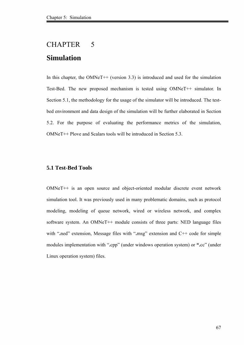
Chapter 5: Simulation
67
CHAPTER 5
Simulation
In this chapter, the OMNeT++ (version 3.3) is introduced and used for the simulation
Test-Bed. The new proposed mechanism is tested using OMNeT++ simulator. In
Section 5.1, the methodology for the usage of the simulator will be introduced. The test-
bed environment and data design of the simulation will be further elaborated in Section
5.2. For the purpose of evaluating the performance metrics of the simulation,
OMNeT++ Plove and Scalars tools will be introduced in Section 5.3.
5.1 Test-Bed Tools
OMNeT++ is an open source and object-oriented modular discrete event network
simulation tool. It was previously used in many problematic domains, such as protocol
modeling, modeling of queue network, wired or wireless network, and complex
software system. An OMNeT++ module consists of three parts: NED language files
with “.ned” extension, Message files with “.msg” extension and C++ code for simple
modules implementation with “.cpp” (under windows operation system) or “.cc” (under
Linux operation system) files.

Chapter 5: Simulation
68
5.1.1 OMNeT++ Module
An OMNeT++ simulator includes stratified embedded model. The model depth is
infinite which allows users to draw in simulation environment, for practical system
logic structure. Each module communicates through the information transmission and
the information may include any complex data structure. Besides, each module can
directly send messages to the target through the gate or line, otherwise, the messages
can be transmitted through the path in advance.
Each module may have its own parameters, which can be used to customize module, or
be used to determine the behavior or simulated topology parameters. The behaviour can
be embedded in the bottom module (basic modules or simple modules) of the simulated
network. Modules can be combined to form a compound module, and each module can
be connected with another module via gates. These simple modules can use simulation
class library and be programmed in C++. All of model is a compound module, called
simulation network in OMNeT++. Figure 5.1 shows the sub modules and parent models
connection, and Figure 5.2 presents the relationship of a simple module and a
compound module.
Figure 5.1: Submodules and Parent Module Connection (usman.html)
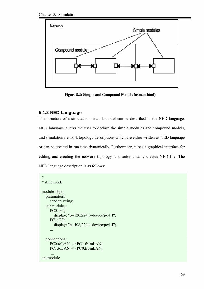
Chapter 5: Simulation
69
Figure 5.2: Simple and Compound Models (usman.html)
5.1.2 NED Language The structure of a simulation network model can be described in the NED language.
NED language allows the user to declare the simple modules and compound models,
and simulation network topology descriptions which are either written as NED language
or can be created in run-time dynamically. Furthermore, it has a graphical interface for
editing and creating the network topology, and automatically creates NED file. The
NED language description is as follows:
// // A network module Topo parameters: sender: string; submodules: PC0: PC; display: "p=120,224;i=device/pc4_l"; PC1: PC; display: "p=408,224;i=device/pc4_l"; ... connections: PC0.toLAN --> PC1.fromLAN; PC1.toLAN --> PC0.fromLAN; ... endmodule

Chapter 5: Simulation
70
5.1.3 OMNeT++ Simulation Programs
OMNeT++ simulations system provides two components: user interfaces and simulation
kernel.
The simulation system can use animation and graphical user interfaces, and can be run
under windows or various Linux operating systems using c++ compilation. These user
interfaces are used to control simulation running, and allowed user to change parameters
inside the model. User can make the internals of the model visible, and debug the
simulation project by utilizing the graphical user interface. There are many user
interfaces written in C++, and compiled into some libraries. OMNeT++ simulation
kernel manages the simulation class library and simulation running. It is written in C++
code and compiled to form a library file (with .a or .lib extension) too.
The automatic command like opp_nmakemake (under windows operation system) or
opp_makemake (under Linux operation system) is used to compile the simulation kernel
and user interface components. An overview of the compiled process is shown in Figure
5.3.

Chapter 5: Simulation
71
Figure 5.3: Simulation Building And Running Process
5.2 Simulation
5.2.1 Test-Bed Design
OMNeT++ is a popular simulation software in colleges and enterprises. It offers many
module component libraries. These components include network general module, like as
link node, queue and group. However, as WiMAX is a relatively new network protocol,
OMNeT++ does not offer MAC module for simulating WiMAX network. As this
research focuses on WiMAX network layer 2, it is crucial to add a new MAC protocol
module in OMNeT++ simulator. Based on the detailed study OMNeT++ simulator and
analysis of the current WiMAX QoS architecture, a network simulation topology
structure of WiMAX system is designed and shown in Figure 5.4.
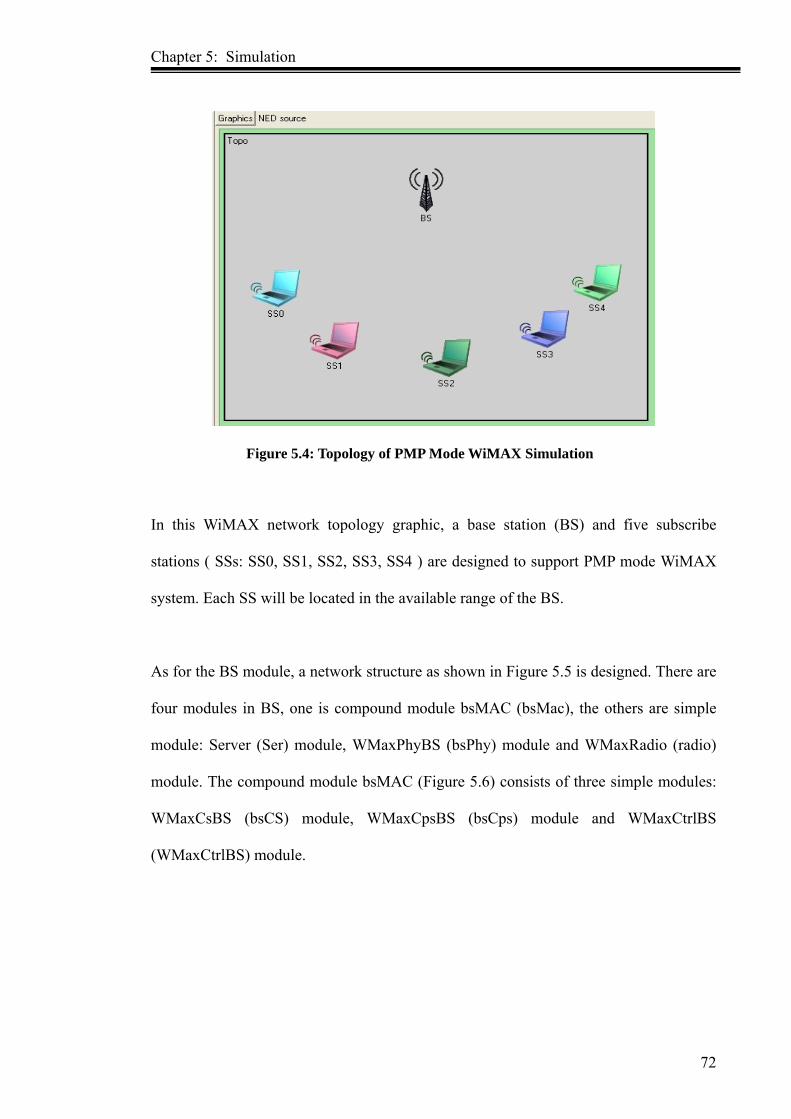
Chapter 5: Simulation
72
Figure 5.4: Topology of PMP Mode WiMAX Simulation
In this WiMAX network topology graphic, a base station (BS) and five subscribe
stations ( SSs: SS0, SS1, SS2, SS3, SS4 ) are designed to support PMP mode WiMAX
system. Each SS will be located in the available range of the BS.
As for the BS module, a network structure as shown in Figure 5.5 is designed. There are
four modules in BS, one is compound module bsMAC (bsMac), the others are simple
module: Server (Ser) module, WMaxPhyBS (bsPhy) module and WMaxRadio (radio)
module. The compound module bsMAC (Figure 5.6) consists of three simple modules:
WMaxCsBS (bsCS) module, WMaxCpsBS (bsCps) module and WMaxCtrlBS
(WMaxCtrlBS) module.

Chapter 5: Simulation
73
Figure 5.5: Topology of BS Module
Figure 5.6: Topology of bsMAC Module
For the SS module, the topology graphic is shown in Figure 5.7. It consists of one
compound module ssMAC (ssMac) and three simple modules: ssInfo (ssInfo) module,
App (App) module and WMaxPhySS (ssPhy) module. The compound module ssMAC
structure (Figure 5.8) is the same as bsMAC module. ssMAC module include three
simple modules too. They are WMaxCsSS (ssCS) module, WMaxCpsSS (ssCps)
module and WMaxCtrlSS (WMaxCtrlSS) module respectively.

Chapter 5: Simulation
74
Figure 5.7: Topology of SS Module
Figure 5.8: Topology of ssMAC Module
5.2.2 WiMAX Simulation Process A scenario of 5 SSs and 1 BS for WiMAX network (PMP) is simulated and the
bandwidth allocation grant process is introduced. The process includes two directions:
uplink direction (SS to BS) and downlink direction (BS to SS). From the scenario, the
simulated result, which approximates the real WiMAX network environment will be
generated.

Chapter 5: Simulation
75
As for the uplink direction (SS sends data to BS), when SS and BS begin to operate, the
initial module “ssCps” will send the RNG_REQ message. After BS receives the ranging
message, the corresponding module “bsCps” will send RNG_RSP message, which
includes BS allocated BCID (Basic Connection Identifier) to SS. This is mainly for
utilizing the ranging process later.
When a connection is established between BS and SS, both BS and SS can transmit data
to each other. After “ssMac” module receives the data from the upper layer (“App”
module), the “WMaxCtrlSS” module will calculate the size number, which includes all
of DSA bandwidth request. This is followed, by SS sending bandwidth request message
to BS. When BS receives the message, “bsCtrl” module will decide whether to accept
the DSA request, depending on the current bandwidth resource. If BS accepts SS
bandwidth request, BS will allocate suitable bandwidth to SS, and guarantee the BS and
SS communication.
After SS gets the bandwidth response message by UL-map, “ssCps” module will adopt
RRMF algorithm for scheduling the different SF queue to send data (when UGS service
flow is created). For the ertPS and rtPS service flow queue, it will adopt the EDF
algorithm to scheduling the data, according to the QoS demand. As BE service flow
does not incorporate QoS demand and nrtPS service flow characters, the HRN
algorithm is adopted to schedule the data. The SS scheduler depends on the different SF
priority to work and the sequence is: UGS、ertPS、rtPS、nrtPS、BE. The downlink
direction process is similar to the uplink direction in the simulation.

Chapter 5: Simulation
76
The CPS module core code of WiMAX network MAC layer in this simulation is shown
as follows:
WMaxCps::WMaxCps()
{
GateIndex = 0;
queuedMsgsCnt = 0;
this->CDMAQueue = new cQueue("CDMAQueue");
WATCH_LIST(Conns);
}
void WMaxCps::stringUpdate() {
if (ev.isGUI()) {
// count all messages in the queue
stringstream displayIt;
displayIt << queuedMsgsCnt << "msgs in " << Conns.size() << " queues.";
displayString().setTagArg("t",0, (displayIt.str()).c_str());
}
}
bool WMaxCps::addConn(WMaxConn conn)
{
std::stringstream ss_cid;
std::string st_cid;
ss_cid << conn.cid;
ss_cid >> st_cid;
std::string name = "SendQueue, CID: " + st_cid;
conn.queue = new cQueue(name.c_str());
stringstream tmp;
switch (conn.type) {
case WMAX_CONN_TYPE_UGS:
tmp << "UGS: msr=" << conn.qos.ugs.msr << ", latency=" << conn.qos.ugs.latency
<< ", jitter=" << conn.qos.ugs.jitter<< ", priority=" << conn.qos.ugs.priority;
break;
case WMAX_CONN_TYPE_ERTPS:
tmp << "ERTPS: msr=" << conn.qos.ertps.msr << ", mrr=" << conn.qos.ertps.mrr<< ",
latency=" << conn.qos.ertps.latency << ", jitter=" << conn.qos.ertps.jitter<< ",
priority=" << conn.qos.ertps.priority;
break;
case WMAX_CONN_TYPE_RTPS:
tmp << "rtPS: msr=" << conn.qos.rtps.msr << ", mrr=" << conn.qos.rtps.mrr
<< ", latency=" << conn.qos.rtps.latency<< ", priority=" << conn.qos.rtps.priority;
break;
case WMAX_CONN_TYPE_NRTPS:
tmp << "nrtPS: msr=" << conn.qos.nrtps.msr << ", mrr=" << conn.qos.nrtps.mrr
<< ", priority=" << conn.qos.nrtps.priority;
break;
case WMAX_CONN_TYPE_BE:
tmp << "BestEffort: msr=" << conn.qos.be.msr<< ", priority=" <<
conn.qos.be.priority;
break;
}

Chapter 5: Simulation
77
cGate *target = gate("toCtrl", conn.gateIndex);
target = target->toGate();
cModule * owner = target->ownerModule();
if (dynamic_cast<WMaxCtrlSS*>(owner)) {
conn.controlConn = true;
}
else if (dynamic_cast<WMaxCtrlBS*>(owner)) {
conn.controlConn = true;
} else {
conn.controlConn = false;
}
Log(Notice) << "Adding connection: sfid=" << conn.sfid << ", cid=" << conn.cid << ",
type="
<< tmp.str() << ", controlConn=" << (conn.controlConn?"YES":"NO")
<< ", connected to: " << owner->fullName() << LogEnd;
//todo - check if CID and sfid are unique
Conns.push_back(conn);
return true;
}
bool WMaxCps::delConn(uint16_t cid)
{
for (list<WMaxConn>::iterator it = Conns.begin(); it!=Conns.end(); it++) {
if (it->cid==cid) {
delete it->queue;
Conns.erase(it);
Log(Notice) << "Connection (cid=" << cid << ") removed." << LogEnd;
return true;
}
}
Log(Error) << "Unable to delete connection with cid=" << cid << "." << LogEnd;
return false;
}
void WMaxCps::printDlMap(WMaxMsgDlMap * dlmap)
{
Log(Debug) << " --- DL-MAP (" << dlmap->getIEArraySize() << " IE(s) ---" << LogEnd;
if (!logger::willPrint(logger::Debug))
return;
for (int i=0; i<dlmap->getIEArraySize(); i++) {
WMaxDlMapIE &ie = dlmap->getIE(i);
Log(Debug) << "IE[" << i << "]: cid=" << ie.cid << ", length=" << ie.length << ",
symbols=" << ie.symbols << LogEnd;
}
}
void WMaxCps::printUlMap(WMaxMsgUlMap * ulmap)
{
Log(Debug) << " --- UL-MAP: " << ulmap->getIEArraySize() << " IE(s) ---" << LogEnd;
if (!logger::willPrint(logger::Debug))
return;
for (int i=0; i<ulmap->getIEArraySize(); i++) {
WMaxUlMapIE &ie = ulmap->getIE(i);
Log(Debug) << "IE[" << i << "]: cid=" << ie.cid << ", uiuc=" << ie.uiuc;
Chapter 5: Simulation
78
5.2.3 Simulation Data Design
In order to evaluate the new mechanism, five subscribe stations and one base station are
utilized in the simulation environment. In the uplink direction, the schedule is not
according to each connection, but it is based on each SS. BS allocates the bandwidth
which belongs to all of the service flow connection of SS. Thus, SS will depend on the
grant bandwidth capacity to adjust the modulation and coding for transmitting data of
different service flow dynamically.
In the simulator, a maximum bandwidth 10 M at BS and 3 M at SS is adopted. One
frame length is 5 ms, and 48 symbols in one frame. There, 44 symbols for data
transmission and 4 symbols for transmitting management message. The QPSK is
selected, 16QAM and 64QAM state for AMC in the simulation and each state
corresponding value is 2, 4, 6 bits percent symbol. If the simulation time is 300 seconds,
it will be stopped at 0s, 50s, 100s, 150s, 200s, 250s and 300s. Pause time 0s means that
the WiMAX network BS and SS do not work. After about 20s, when WiMAX system
finishes the initial phase and the SS and BS has completed sending some data, the
second pause time is set at 50s. The last pause time is 300s (after 5 minutes), the
simulation topology will be similar as the real WiMAX network environment. These
result data will be used to evaluate the new mechanism.
Finally, the collected data will be analyzed using OMNeT++ Scalars and Plove tools.
Microsoft Office Excel spreadsheet software will be used to analyze the “.sna” file data.
The simulation parameters and set values details are as per Table 5.1.

Chapter 5: Simulation
79
Table 5.1: Simulation Data Value Parameters Value Number of SSs 5 Number of BS 1 Topology mode PMP BS Bandwidth 10 MHz SS Bandwidth 2 MHz Duplex mode TDD Symbols per frame 48 FFT size 1024 Data Sub-carries 840 Frame length 5 ms QPSK1/2 2 ( 1Bits / Symbol) 16QAM 3/4 4 ( 3Bits / Symbol) 64QAM 3/4 6 (4.5Bits / Symbol) Simulation time 300s MinDelayRng 0.020s MaxDelayRng 0.040s MinDelayScn 0.020s MaxDelayScn 0.040s
In the simulation test, 5 service flows: UGS, ertPS, rtPS, nrtPS and BE are adopted.
UGS is a fixed transmission rate, and is setup at value 64 kbps with the maximum
latency time of 20 ms. The ertPs and rtPS service flows are unfixed rate, so the ertPS
service flow can adopt maximum sustained rate at 256 kbps with minimum reserved
rate of 32 kbps, maximum latency time same UGS service; the rtPS service flow adopts
maximum sustained rate and minimum reserved rate at 512 kbps and 32 kbps
respectively, with the latency time of 50 ms. For nrtPS service flow, the maximum
sustained rate and minimum reserved rate are 1024 kbps and 10 kbps respectively, the
maximum latency time is 100 ms. Because BE service flow does not have QoS demand,
thus the minimum reserved rate of 0 kbps is adopted, with maximum sustained rate of
1024 kbps. The detailed parameters of different service flows are shown in Table 5.2.
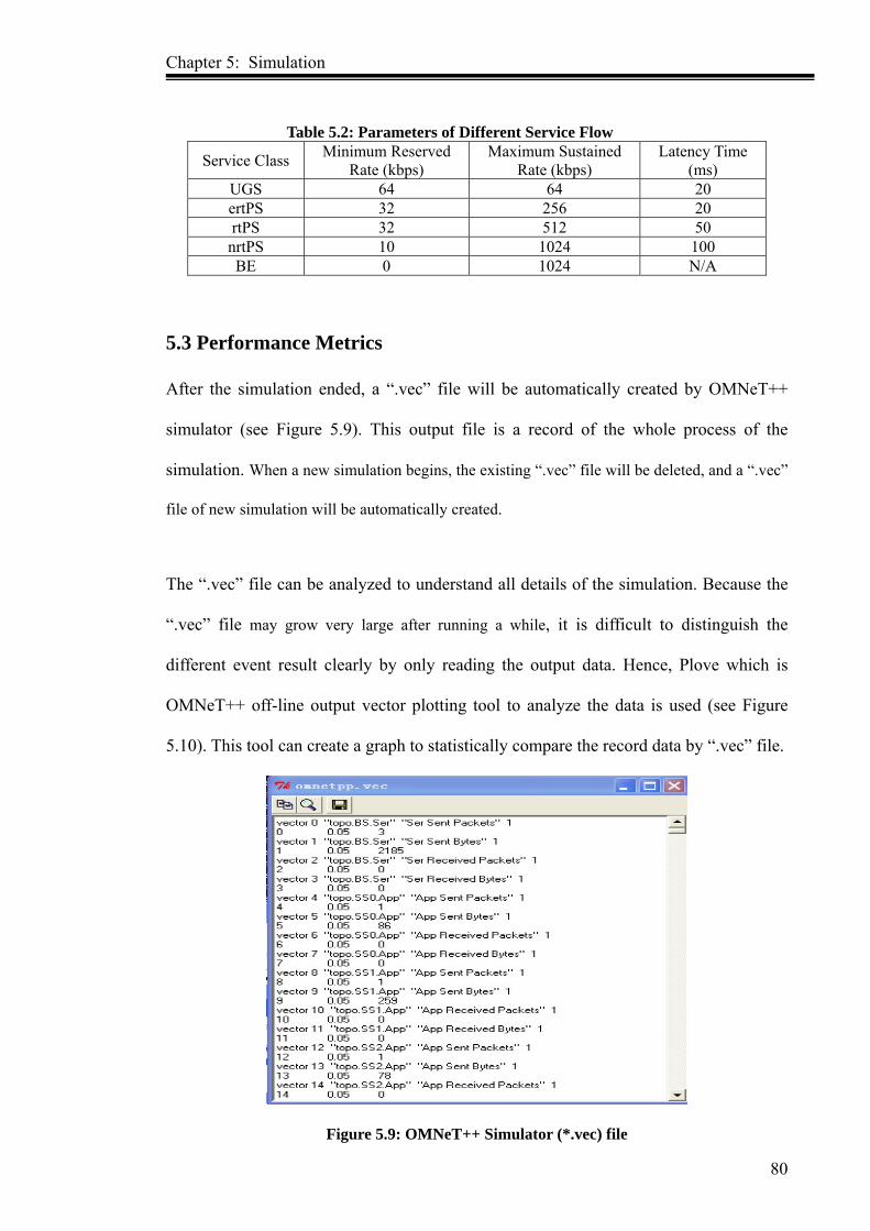
Chapter 5: Simulation
80
Table 5.2: Parameters of Different Service Flow
Service Class Minimum Reserved Rate (kbps)
Maximum Sustained Rate (kbps)
Latency Time (ms)
UGS 64 64 20 ertPS 32 256 20 rtPS 32 512 50
nrtPS 10 1024 100 BE 0 1024 N/A
5.3 Performance Metrics After the simulation ended, a “.vec” file will be automatically created by OMNeT++
simulator (see Figure 5.9). This output file is a record of the whole process of the
simulation. When a new simulation begins, the existing “.vec” file will be deleted, and a “.vec”
file of new simulation will be automatically created.
The “.vec” file can be analyzed to understand all details of the simulation. Because the
“.vec” file may grow very large after running a while, it is difficult to distinguish the
different event result clearly by only reading the output data. Hence, Plove which is
OMNeT++ off-line output vector plotting tool to analyze the data is used (see Figure
5.10). This tool can create a graph to statistically compare the record data by “.vec” file.
Figure 5.9: OMNeT++ Simulator (*.vec) file

Chapter 5: Simulation
81
Figure 5.10: OMNeT++ Off-line Tool Plove
The data changes during simulation can be studied by the inspector module contents
(like figure 5.11). Furthermore, the snapshot file can be saved as well (see Figure 5.12)
to analyze the simulation process, and collect data by output “.sca” file. Scalars which
are OMNeT++ off-line tool is also used to create some chart for analyzing the
simulation result data of “.sca” file. Unlike “.vec” file, the saved “.sca” file is not
deleted when a new simulation begins. Instead, these new data are just appended to the
old “.sca” file. Thus, output data can be collected and analyzed together from multiple
simulation runs with different input parameters.

Chapter 5: Simulation
82
Figure 5.11: Simulation Inspector Content
Figure 5.12: Simulation Snapshot File Content
As the objective is to evaluate the performance of the new mechanism in WiMAX
system, the network throughput, schedule probability (SP) and queuing delay time with
before and after using our mechanism (ODBA) in WiMAX system will be analyzed.
Thereby, in this thesis, the Plove and Scalars tools will be used to analyze the result data
after the end of the simulation. The details of the data analysis and discussion of the
simulation result will be presented in the following chapter.

Chapter 6: Data Analysis and Discussion
83
CHAPTER 6
Data Analysis and Discussion
In this chapter, the results from the data collected in the simulation process will be
discussed. The results are presented based on the queuing delay time, scheduled
probability (SP) and throughput as performance metrics, in order to evaluate the QoS of
WiMAX network under ODBA mechanism. Through the arrangement of simulation
result data, by “omnetpp.out”, “omnetpp.sca”, “omnetpp.sna” and “omnetpp.vec” files,
the data is analysed, evaluated and discussed for the impacts on the performance of
ODBA mechanism in WiMAX system.
6.1 Introduction
In the simulation processing, three scenarios are designed to obtain the scheduled
probability (SP), queuing delay time and throughput simulation data results.
In the first scenario, the SP value is fixed to evaluate the different service flow fairness
and performance in WiMAX system. The design simulation time is fixed at maximum
of 100 second. There are 5 service flows in each SS and BS, which are UGS, ertPS, rtPS,
nrtPS and BE service flow respectively. One by one service flow is added in each
second. The data is collected at 1s, 10s, 20s, 30s, 40s, 50s, 60s, 70s, 80s, 90s and 100s.
The SP of each service flow is calculated, based on the created SF and scheduled SF. SP
performance metric is as the following (Appendix A shows the simulation data):
SP = scheduled_packetSize(bits) /created_packetSize(bits)
Chapter 6: Data Analysis and Discussion
84
In the second simulation scenario, the queuing delay time value factor and its impact are
tested. The queuing delay time occurs in the buffer of each node which is the waiting
time for a service flow from the provisioned state until the scheduled state. In the design,
the simulator is running by 300s, and the data from 0s, 1s … to 300s will be taken out
(Appendix B shows the full data). Each SS and BS will still include 5 service flows:
UGS, ertPS, rtPs, nrtPS and BE. The calculation of the queuing delay time will be
according to the each of the SF states: provisioned, admitted and activated. The time is
equal to the simulation time of each SF scheduled state time minus provisioned state
time.
The last simulation scenario is for calculating network throughput, includes peak
throughput and average throughput. When each SS sends data to BS, but BS does not
send data to SS, the UL peak throughput can be obtained. In reverse, when only BS
sends data to SS, the DL peak throughput can be obtained. The simulator will be
running at 300s in each situation. Seven phases for the DL and UL proportion are
designed : 1:0, 3:1, 2:1, 1:1, 1:2, 1:3, 0:1 respectively (Appendix C shows the full data).
When both SS and BS send data to each other, then the average throughput value can be
generated.
The simulation data will be analysed and the result will be discussed in the following
sections.
6.2 Scheduled Probability (SP) With the adoption of the new mechanism ODBA in WiMAX system, the fairness of
different SF will be discussed. Different service flow will be used to evaluate the packet
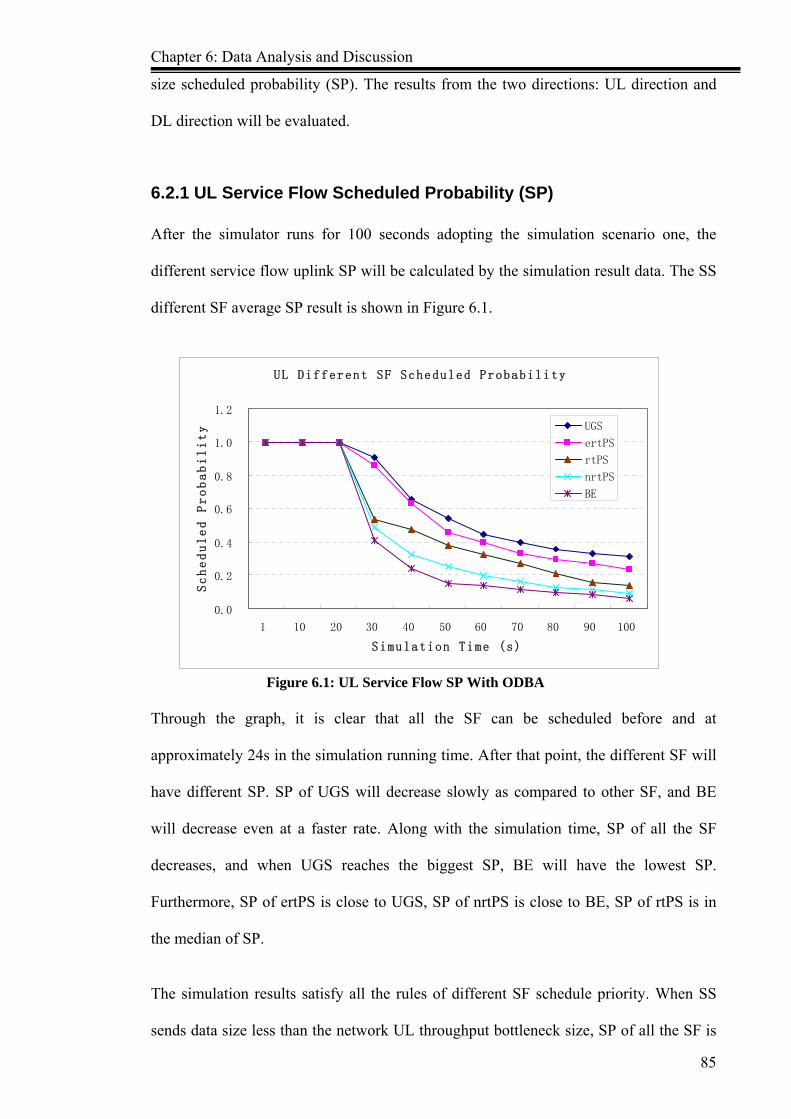
Chapter 6: Data Analysis and Discussion
85
size scheduled probability (SP). The results from the two directions: UL direction and
DL direction will be evaluated.
6.2.1 UL Service Flow Scheduled Probability (SP) After the simulator runs for 100 seconds adopting the simulation scenario one, the
different service flow uplink SP will be calculated by the simulation result data. The SS
different SF average SP result is shown in Figure 6.1.
UL Different SF Scheduled Probability
0.0
0.2
0.4
0.6
0.8
1.0
1.2
1 10 20 30 40 50 60 70 80 90 100
Simulation Time (s)
Scheduled Probability UGS
ertPS
rtPS
nrtPS
BE
Figure 6.1: UL Service Flow SP With ODBA Through the graph, it is clear that all the SF can be scheduled before and at
approximately 24s in the simulation running time. After that point, the different SF will
have different SP. SP of UGS will decrease slowly as compared to other SF, and BE
will decrease even at a faster rate. Along with the simulation time, SP of all the SF
decreases, and when UGS reaches the biggest SP, BE will have the lowest SP.
Furthermore, SP of ertPS is close to UGS, SP of nrtPS is close to BE, SP of rtPS is in
the median of SP.
The simulation results satisfy all the rules of different SF schedule priority. When SS
sends data size less than the network UL throughput bottleneck size, SP of all the SF is

Chapter 6: Data Analysis and Discussion
86
1. When the SS sends data size more than network UL throughput bottleneck size, SP of
different SF will decrease. Finally, when SS sends the optimal data size more than the
network UL throughput bottleneck size, the lowest SP of BE can still be scheduled.
Even if SP is at minimum, there is no starvation of SF occurs in WiMAX system.
6.2.2 Comparison of UL Scheduled Probability (SP) The simulation result data was first obtained without adopting the ODBA mechanism.
Then, the data generated by adopting ODBA mechanism, is compared to the data
without adopting the ODBA mechanism condition. This is to evaluate the fairness of
different service flow. Figure 6.2 shows the compared result.
Figure 6.2: Comparison SP of UL Direction With ODBA and Without ODBA
As shown in Figure 6.2, the ODBA service flows are UGS, ertPS, rtPS, nrtPS and BE,
otherwise, ugs, ertps, rtps, nrtps and be means the result is of without ODBA service
flow. From the graph, it is shown clearly that after SS sends data size more than the
network UL throughput bottleneck, SP of ugs and ertps will be more than SP of UGS
and ertPS; SP of rtps, nrtps and ‘be’ are less than erPS, nrtPS and BE. At the simulation
UL Service Flow SP With ODBA and Without ODBA
0.0
0.2
0.4
0.6
0.8
1.0
1 10 20 30 40 50 60 70 80 90 100 Simulation Time (s)
Sche
dule
d Pr
obab
ility
UGS ugs ertPS
ertps
rtPS
rtps
nrtPS
nrtps
BE be

Chapter 6: Data Analysis and Discussion
87
time around 60s, the SP of ‘be’ and nrtps is 0, which means that the starvation of SF has
occurred in WiMAX system.
In comparison of SP with ODBA and without ODBA through Figure 6.2, it is known
that when SS sends packet size more than the network UL throughput bottleneck, SP of
rtPS, nrtPS and BE will decrease slowly in contrast to rtps, nrtps and be. Even though
the SP of UGS and ertPS is less than ugs and ertps, the performance of all the SF with
ODBA mechanism is better than without ODBA mechanism in WiMAX system. The
reason for this is that the ODBA mechanism considers the fairness of different service
flow more than without ODBA mechanism. It can avoid starvation of SF occurs under
condition of SS requests more UL bandwidth. Thus ODBA mechanism can improve the
fairness of different service flow in WiMAX system.
6.2.3 DL Service Flow Scheduled Probability (SP) The DL direction service flow of SP, and the BS of different SF and the average SP
result is shown in Figure 6.3. From the graph, all of the SF can be scheduled before and
at around 46s. After that point, the SP of different SF is different. The DL direction
service flow SP of UGS, ertPS, nrtPS and BE is similar as the UL direction.

Chapter 6: Data Analysis and Discussion
88
DL Different SF Scheduled Probability
0.0
0.2
0.4
0.6
0.8
1.0
1 10 20 30 40 50 60 70 80 90 100
Simulation Time (s)
Scheduled Probability
UGS
ertPS
rtPS
nrtPS
BE
Figure 6.3: DL Service Flow SP With ODBA As BS sends packet size which is less than the network DL throughput bottleneck size,
the SP of all the SF is 1. While the BS sends data size more than the network DL
throughput bottleneck size, SP of different SF will decrease. Otherwise, when BS sends
the optimal packet size more than the network DL throughput bottleneck size, SP of BE
and nrtPS service flow are insignificant. When the SP is minimum, it means that the BE
and nrtPS service flow can still be scheduled, and no starvation of SF occurs in WiMAX
system.
6.2.4 Comparison of DL Scheduled Probability (SP) The simulation result data of both with ODBA mechanism and without ODBA
mechanism is compared, for the purpose of evaluating the fairness of DL direction
different service flow. The compared result is shown in Figure 6.4. The UGS, ertPS,
rtPS, nrtPS and BE, means ODBA service flow SP, and the ugs, ertps, rtps, nrtps and be
means without ODBA service flow. From the graph, after the BS sends packet size
more than the network DL throughput bottleneck, SP of ugs and ertps will be more than
SP of UGS and ertPS; SP of rtps, nrtps and ‘be’ will be less than erPS, nrtPS and BE. At

Chapter 6: Data Analysis and Discussion
89
the simulation time of around 80s, the SP of ‘be’ and nrtps has decreased to 0, which
means that the starvation of SF has occurred in DL direction.
Figure 6.4: Comparison of DL SP With ODBA and Without ODBA
In comparison of DL direction for different service flows of SP, between with ODBA
and without ODBA as illustrated in Figure 6.4, when BS sends packet size more than
network DL throughput bottleneck, SP of rtPS, nrtPS and BE will decrease slower than
rtps, nrtps and ‘be’. Even though the SP of UGS and ertPS is less than ugs and ertps, the
performance of all the SF with ODBA mechanism is better than without ODBA
mechanism in DL direction. The reason for this is because the new ODBA mechanism
can avoid starvation service flow occurs when DL requires bandwidth more than DL
throughput bottleneck size. Thus, ODBA can improve the fairness as compared to
without ODBA.
DL Service Flow SP With ODBA and Without ODBA
0.0
0.2
0.4
0.6
0.8
1.0
1 10 20 30 40 50 60 70 80 90 100 Simulation Time (s)
Scheduled Probability
UGS
ugs
ertPS
ertps
rtPS
rtps
nrtPS
nrtps
BE
be

Chapter 6: Data Analysis and Discussion
90
6.3 Queuing Delay Time Scenario 2 is used to obtain the simulation result data, for analyzing the performance of
queuing delay time with ODBA in WiMAX system. For the queuing delay time, the
focus will be on UL direction. Thus, only the performance of queuing delay time in SS
will be discussed.
6.3.1 Different Service Flow Queuing Delay Time The data which are collected from the simulation Scenario 2 will be used to analyze the
performance of queuing delay time with ODBA in WiMAX system. Figure 6.5 shows
the result of different service flow queuing delay time.
Different SF Queuing Delay Time
0.0000
0.0002
0.0004
0.0006
0.0008
0.0010
0.0012
0.0014
0.0016
0.0018
0.0020
0 50 100 150 200 250 300
Simulation Time (s)
Queuing Delay Time (s)
UGS
ertPS
rtPS
nrtPS
BE
Figure 6.5: Different Service Flow Queuing Delay Time With ODBA Based on the data in Figure 6.5, UGS has the lowest queuing delay time, and BE has the
highest queuing delay time. The queuing delay time of ertPS is less than rtPS, and rtPS
less than nrtPS. Likewise, queuing delay time of nrtPS is close to BE, ertPS and rtPS is
close to UGS. Besides, the queuing delay time of BE and nrtPS is more than rtPS, ertPS

Chapter 6: Data Analysis and Discussion
91
and UGS. The average queuing delay time of different service flow is calculated as
shown in Figure 6.6.
Average Queuing Delay Time
0.0000
0.0002
0.0004
0.0006
0.0008
0.0010
0.0012
0.0014
0.0016
0.0018
UGS ertPS rtPS nrtPS BE
Different Service Flow
Queuing Delay Time (s)
Figure 6.6: Average Queuing Delay Time Of Different Service Flow With ODBA
In Figure 6.6, the average queuing delay time from the order from low to high is : UGS,
ertPS, rtPS, nrtPS and BE. The reason for this is because different service flow has
different priority, and the simulation result is according to the QoS demand of WiMAX
system.
6.3.2 Comparison of ODBA And Others Scheduling Algorithm From the research paper of Jin & Chun (2008), the average queuing delay time has been
discussed based on the WFQ (Weighted Fair Queuing), RED (Random Early Detection),
RIO (Red With In/Out), FQ (Fair Queuing), DRR (Deficit Round Robin) and Drop
(Drop Tail) schedule algorithms. The comparison of queuing delay time of different
algorithms is shown in Figure 6.7.
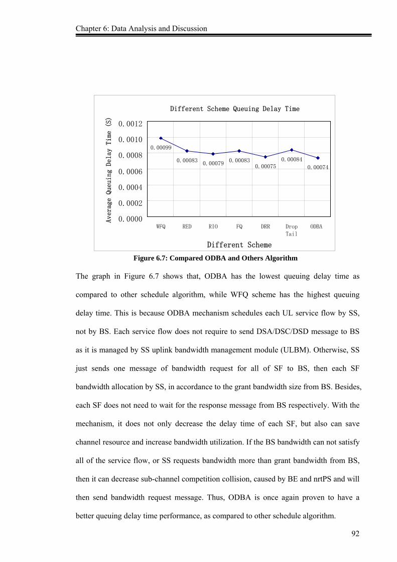
Chapter 6: Data Analysis and Discussion
92
Figure 6.7: Compared ODBA and Others Algorithm
The graph in Figure 6.7 shows that, ODBA has the lowest queuing delay time as
compared to other schedule algorithm, while WFQ scheme has the highest queuing
delay time. This is because ODBA mechanism schedules each UL service flow by SS,
not by BS. Each service flow does not require to send DSA/DSC/DSD message to BS
as it is managed by SS uplink bandwidth management module (ULBM). Otherwise, SS
just sends one message of bandwidth request for all of SF to BS, then each SF
bandwidth allocation by SS, in accordance to the grant bandwidth size from BS. Besides,
each SF does not need to wait for the response message from BS respectively. With the
mechanism, it does not only decrease the delay time of each SF, but also can save
channel resource and increase bandwidth utilization. If the BS bandwidth can not satisfy
all of the service flow, or SS requests bandwidth more than grant bandwidth from BS,
then it can decrease sub-channel competition collision, caused by BE and nrtPS and will
then send bandwidth request message. Thus, ODBA is once again proven to have a
better queuing delay time performance, as compared to other schedule algorithm.
Different Scheme Queuing Delay Time
0.00099
0.00083 0.00079 0.000830.00075
0.00084 0.00074
0.0000
0.0002
0.0004
0.0006
0.0008
0.0010
0.0012
WFQ RED RIO FQ DRR Drop Tail
ODBA
Different Scheme
Average Queuing Delay Time (S)

Chapter 6: Data Analysis and Discussion
93
6.4 Throughput Throughput refers to the MAC layer, whch is the throughput of statistics in BS side.
Two values namely peak throughput and average throughput are calculated to evaluate
the performance of throughput with ODBA. The peak throughput includes three
parameters: UL peak throughput, DL peak throughput and DL/UL peak throughput of
different proportion respectively.
6.4.1 Peak Throughput Three times of simulation are conducted. First, BS just receives data from all of SS in
order to know the UL peak throughput from the simulation result data. Secondly, BS
just sends data to SSs, so the DL peak throughput will be known. Lastly, both BS and
SS send data according to the DL/UL bandwidth request proportion.
UL peak throughput
The UL throughput data is collected from “omnetpp.sna” file, in order to see the result
as shown in Figure 6.8
UL throughput
0
4000
8000
12000
16000
0 50 100 150 200 250 300
Simulation Running Time (s)
Throughput (kbps)
Figure 6.8: ODBA Uplink Throughput

Chapter 6: Data Analysis and Discussion
94
From the graph above, the UL throughput is increasing rapidly, the UL peak throughput
occurs at around 34s and the value is 16251 kbps. Since that point, the throughput is
always fluctuating which ranges between 16000 kbps and about 12000 kbps.
DL peak throughput
The DL throughput simulation result data is shown in Figure 6.9. It shows that the DL
throughput is increasing fast, and DL peak throughput occurs at around 23s and the
value is 31421 kbps. The DL throughput is fluctuating as well, after simulation runs
after 23s. The throughput fluctuation ranges between 31000 kbps and about 25000 kbps.
Figure 6.9: ODBA Downlink Throughput
DL/UL Peak Throughput With Different Bandwidth Request Proportion When DL direction and UL direction have different bandwidth request proportion, the
DL/UL peak throughput will be different. In order to evaluate the performance of
WiMAX network better throughput with ODBA, the simulation result data is collected
while DL/UL has different bandwidth request proportion. The result is shown in Figure
6.10.
DL Throughput
0
5000
10000
15000
20000
25000
30000
0 50 100 150 200 250 300 Simulation Running Time (S)
Throughput (kbps)

Chapter 6: Data Analysis and Discussion
95
0
5000
10000
15000
20000
25000
30000
35000
Peak Throughput (kbps)
1:0 3:1 2:1 1:1 1:2 1:3 0:1
DL/UL Bandwidth Ruquest Proportion
DL/UL Peak Throughput
UL
DL
Figure 6.10: DL/UL Peak Throughput With Different Bandwidth Request Proportion
From Figure 6.10, it is shown that when DL/UL bandwidth request proportion is 1:0 or
0:1, the peak throughput will be similar to DL peak throughput or UL peak throughput.
With DL/UL direction bandwidth request proportion changed, the DL/UL peak
throughput is changed as well. Both DL and UL peak throughput are increasing with
bandwidth request proportion changing greater. In reverse, the DL/UL peak throughput
is decreasing with bandwidth request proportion changing smaller.
Performance Of ODBA Peak Throughput
Peak throughput is a good metric for comparative purposes. It is able to identify the
peak throughput of different DL/UL ratio without adopting ODBA mechanism from the
paper (Mobile WiMAX-Part I, 2006). Thus, the comparison of ODBA and without
ODBA result is shown in Figure 6.11 which describes the performance of DL direction
peak throughput. Figure 6.12 describes the performance of UL direction peak
throughput.

Chapter 6: Data Analysis and Discussion
96
Figure 6.11: DL Peak Throughput Performance
Figure 6.12: UL Peak Throughput Performance
As shown in Figure 6.11, the DL peak throughput with ODBA and without ODBA has
small differences. When DL/UL ratio is 1:0 and 1:1, ODBA peak throughput is slightly
lower than without ODBA peak throughput. When DL/UL ratio is 3:1 and 2:1, ODBA
peak throughput is slightly higher than without ODBA peak throughput. The simulation
conducted also considers DL bandwidth request size lesser than UL bandwidth request
0
5
10
15
20
25
30
35
Peak Throughput (mbps)
1:0 3:1 2:1 1:1 1:2 1:3 0:1 DL Bandwidth Request Proportion
Comparison of ODBA and Without ODBA 1
DL(ODBA) DL
Comparison of ODBA and Without ODBA 2
0 2 4 6 8 10 12 14 16 18
1:0 3:1 2:1 1:1 1:2 1:3 0:1 UL Bandwidth Request Proportion
Peak Throughput (Mbps)
UL(ODBA)
UL

Chapter 6: Data Analysis and Discussion
97
size situation. It is assumed that the DL/UL ratio is 1:2 and 1:3 while the DL peak
throughput is 10.17 Mbps and 7.42 Mbps respectively.
ODBA peak throughput is not always higher than without ODBA peak throughput in
different DL/UL ratio situation. However, as understood, the situation which the DL/UL
ratio is 1:0 or 1:1, rarely occurs in reality in WiMAX network. In WiMAX system, most
of DL/UL ratio is close to 3:1 or 2:1. Hence, ODBA performance of DL peak
throughput is better than without ODBA system.
From Figure 6.12, it is known that the UL peak throughput with ODBA is higher than
without ODBA, in all DL/UL ratio situations. ODBA peak throughput is slightly higher
than without ODBA, while DL/UL ratio is 3:1. When DL/UL is 0:1, ODBA peak
throughput is much higher than without ODBA. ODBA mechanism decreases the UL
queuing delay time (proven in Section 6.3), and saves UL bandwidth consumption.
Furthermore, ODBA is allocating bandwidth dynamically according to the DL/UL
bandwidth request ratio, hence, it can increase utilization of bandwidth resources. The
overall performance of UL peak throughput is better with ODBA as compared to
without ODBA system.

Chapter 6: Data Analysis and Discussion
98
6.4.2 Average Throughput
According to the research paper by Lin (2008), it is able to know the average throughput
of WFQ, RED, RIO, FQ, DRR and Drop schedule algorithms in WiMAX system. The
comparison of different algorithm average throughput is shown in Figure 6.13.
Figure 6.13: Different Algorithm Average Throughput
From Figure 6.13, the ODBA average throughput is obviously higher than other
scheduling algorithm. As ODBA mechanism applied in different SF will have different
characteristics, it is important to adopt the suitable algorithm for different SF queuing,
so that the DL/UL scheduling algorithm can improve the lack of different SF queuing
algorithm. As proven and discussed, ODBA mechanism has high scheduled probability
of service flow, lower queuing delay time (see above section) and dynamic allocation of
bandwidth resource. Thereby, ODBA bandwidth performance of average throughput is
better than other scheduling algorithm.
Comparison of Different Algorithm
386.47
371.28
377.84 378.61 377.84 377.52 377.84
360
365
370
375
380
385
390
ODBA WFQ RED RIO FQ DRR DropTail
Different Queuing Algorithm
Ave
rage
Thr
ough
put (
kbps
)

Chapter 6: Data Analysis and Discussion
99
Summary
The WiMAX simulation result is illustrated, discussed and evaluated in this chapter.
The ODBA mechanism performance is measured based on the fairness, queuing delay
time and throughput. It is found that ODBA is capable of providing better fairness of
scheduling, while satisfying the QoS demand of different service flow. ODBA can also
reduce queuing delay time of different service flow, and provide high DL/UL peak
throughput and average throughput. Thereby, ODBA does not only improve fairness of
different service flow, but can also increase throughout of WiMAX. Once again, it is
proven that ODBA mechanism has better performance in WiMAX system.

Chapter 7:Conclusion
100
CHAPTER 7
Conclusion This chapter presents the conclusion and recommendations of the research conducted.
First, the research objective achievement is summarized, and the significance and
contribution of the research are presented. Subsequently, the advantages and
disadvantages of this research are highlighted, and the related future works will be
proposed. Finally, the conclusion of this research is presented.
7.1 Evaluation on Our Research Objective Achievement In this research work a new mechanism for on demand bandwidth allocation in WiMAX
system is designed. This design is called On Demand Bandwidth Allocation (ODBA).
Its purpose is to enhance QoS of WiMAX. The DL direction bandwidth management by
BS, and UL direction bandwidth management by SS. BS dynamically allocates the sub-
carriers for DL/UL according to the DL/UL bandwidth request proportion, while SS of
each service flow does not need to send bandwidth request message to BS. The
bandwidth management of each service flow is scheduled by ULBM module and
scheduler of SS. These can dynamically allocate bandwidth on demand and save
bandwidth resource consumption, to improve the QoS of WiMAX. The performance of
the ODBA has been evaluated in OMNeT++ simulator by using the metrics of
scheduled probability (SP), queuing delay time and throughput.
Many materials of WiMAX network are discussed in Chapter 2, which encourage the
understanding of the research subject. Based on the understanding and evaluation of the
past research materials, the issues in the current WiMAX network are highlighted.
Chapter 7:Conclusion
101
In Chapter 3, the details of the problems of bandwidth allocation faced in WiMAX are
discussed. The methodology of the research to solve the current problem in WiMAX
system is outlined.
The research model design by on demand bandwidth allocation is introduced in Chapter
4. In this chapter, all the features and characters of the new ODBA mechanism are
discussed in details. Two new modules, SFM and ULBM in SS, and a new module BM
in BS are adopted as well.
The ODBA mechanism is simulated by using OMNeT++ simulator in Chapter 5. The
methodology of the usage of OMNeT++ simulator for the Test-Bed is introduced. With
this, the key characters of the simulation environment and its impact on the performance
of the research metrics are identified.
In Chapter 6, the simulation results are analysed and the behaviours of the ODBA
mechanism are evaluated. The performance of SP, queuing delay time and throughput
are compared with other bandwidth allocation algorithms and those without ODBA. The
simulation results show that ODBA has higher SP, shorter queuing delay time and
higher throughput.
7.2 Significance and Contribution The major significance and contribution of this thesis is to provide a new mechanism of
ODBA for WiMAX network. ODBA adopts on demand bandwidth allocation
mechanism for DL/UL direction. It can solve the sub-carriers competition collision and

Chapter 7:Conclusion
102
bandwidth resource wastage problem. The main contributions of this research can be
summarized as follows:
Improving QoS of WiMAX network by using ODBA mechanism.
Solving the current problems faced in WiMAX system.
Writing the simulation code of the proposed mechanism.
Establishing the measurement parameters for evaluating the performance of WiMAX
with ODBA mechanism.
Recommending direction and path for future research endeavors.
This research results have been published in papers by Sun & AbdullahGani (2009)
‘Intelligent Uplink Bandwidth Allocation Based on PMP Mode For WiMAX’. This
paper has been accepted in the 2009 International Conference on Computer Technology
and Development (ICCTD 2009). It is in proceeding by IEEE Computer Society and
will be listed in IEEE Xplore and indexed by Thomson ISI proceeding and Ei
compendex.
On April, 2010, the thesis results have been able to be published in another paper by
Sun, ZhenTao (2010) entitled ‘Improving Throughput By On_Demand Bandwidth
Allocation For WiMAX’. It has been accepted in the 2010 2nd International Conference
on Computer Engineering and Technology (ICCET 2010), and it will be published in
IEEE Xplore, and indexed by Ei compendex and Thomson ISI proceeding.
7.3 Advantages and Disadvantages
There are several advantages and disadvantages of this research and they are discussed
as the following:

Chapter 7:Conclusion
103
7.3.1 Advantages
ODBA improves the fairness of different service flow to reduce the starvation
service flow occurs in WiMAX network.
ODBA decreases the sub-carriers competition collision to efficiently utilize the
bandwidth resource.
ODBA reduces the queuing delay time to increase the throughput of WiMAX.
The proposed mechanism in WiMAX situation is simulated by OMNeT++ simulator,
which can provide convenient environment for future related research works.
The path and direction for future research are introduced.
7.3.2 Disadvantages
In this research, the signal interference of both BS and SS data transmission are not
taken into consideration, which will only occur in real WiMAX network.
The simulation environment of OMNeT++ is limited for simulation of mobile
WiMAX network. The reason is that it does not have any module to support the
situation of intra impact in signals and signal attenuation in WiMAX system.
7.4 Proposed Future Works
In this research, a new mechanism, ODBA is designed to improve the performance of
QoS in WiMAX network. The main focus is to improve the fairness of different service
flow, decrease the queuing delay time and increase the throughput. Thus, in future,
related research needs to work on improving the fairness of different SS, and does not
only decrease the queuing delay time, but also to decrease the delay time which includes
latency and transmission delay. In addition, it is important to consider the signal
Chapter 7:Conclusion
104
interference and the movement of SS which will affect the bandwidth allocation in
mobile WiMAX network.
7.5 Conclusion
This thesis presents ODBA mechanism in WiMAX network. In order to solve the
current issues faced in WiMAX network, and improve QoS demand, a new mechanism,
ODBA is designed and it is an on demand bandwidth allocation mechanism for
WiMAX. ODBA depends on the different characters of different service flow, to adopt
different schedule algorithm. Furthermore, DL/UL direction of different service flow is
scheduled by BS and SS respectively.
The performance of ODBA mechanism and its behaviour are evaluated, analyzed and
compared with other algorithms and those without ODBA in WiMAX network. The
performance has been simulated using OMNeT++ simulator in metrics of scheduled
probability, queuing delay time and throughput. The simulation results show that the
ODBA mechanism has higher network performance than without ODBA in WiMAX
network.

Appendixes
105
Appendixes

Appendix A: DL/UL Different Service Flow Scheduled Probability
106
Appendix A:
UL Different Service Flow Scheduled Probability
Simulated
Time (s) UGS ugs ertPS ertps rtPS rtps nrtPS nrtps BE be
1.00 1.00 1.00 1.00 1.00 1.00 1.00 1.00 1.00 1.00 1.00
10.00 1.00 1.00 1.00 1.00 1.00 1.00 1.00 1.00 1.00 1.00
20.00 1.00 1.00 1.00 1.00 1.00 1.00 1.00 1.00 1.00 1.00
30.00 0.91 1.00 0.86 0.95 0.54 0.49 0.49 0.26 0.41 0.21
40.00 0.66 0.72 0.63 0.69 0.48 0.43 0.32 0.15 0.24 0.11
50.00 0.54 0.60 0.46 0.50 0.38 0.35 0.25 0.10 0.15 0.06
60.00 0.45 0.50 0.40 0.44 0.32 0.29 0.20 0.07 0.14 0.00
70.00 0.40 0.44 0.33 0.36 0.27 0.24 0.16 0.00 0.11 0.00
80.00 0.36 0.40 0.29 0.32 0.21 0.19 0.13 0.00 0.10 0.00
90.00 0.33 0.36 0.27 0.30 0.16 0.14 0.11 0.00 0.08 0.00
100.00 0.31 0.34 0.23 0.25 0.14 0.13 0.09 0.00 0.06 0.00
DL Different Service Flow Scheduled Probability
Simulated
Time (s) UGS ugs ertPS ertps rtPS rtps nrtPS nrtps BE be
1.00 1.00 1.00 1.00 1.00 1.00 1.00 1.00 1.00 1.00 1.00
10.00 1.00 1.00 1.00 1.00 1.00 1.00 1.00 1.00 1.00 1.00
20.00 1.00 1.00 1.00 1.00 1.00 1.00 1.00 1.00 1.00 1.00
30.00 1.00 1.00 1.00 1.00 1.00 1.00 1.00 1.00 1.00 1.00
40.00 1.00 1.00 1.00 1.00 1.00 1.00 1.00 1.00 1.00 1.00
50.00 1.00 1.00 0.91 1.00 0.73 0.66 0.40 0.21 0.31 0.18
60.00 0.89 1.00 0.80 0.88 0.59 0.53 0.33 0.15 0.30 0.17
70.00 0.74 0.81 0.69 0.76 0.50 0.45 0.26 0.10 0.24 0.12
80.00 0.67 0.74 0.62 0.68 0.42 0.38 0.23 0.07 0.20 0.00
90.00 0.59 0.65 0.56 0.62 0.35 0.32 0.19 0.00 0.17 0.00
100.00 0.55 0.61 0.51 0.56 0.29 0.26 0.14 0.00 0.09 0.00

Appendix B: Different Service Flow Queuing Delay Time (s)
107
Appendix B:
Different Service Flow Queuing Delay Time (s)
Simulation Ti ( )
UGS ertPS rtPS nrtPS BE 0 0.00000 0.00000 0.00000 0.00000 0.00000 1 0.00008 0.00018 0.00026 0.00095 0.00109 2 0.00009 0.00021 0.00029 0.00106 0.00122 3 0.00011 0.00025 0.00036 0.00130 0.00150 4 0.00010 0.00023 0.00033 0.00118 0.00136 5 0.00009 0.00021 0.00029 0.00106 0.00122 6 0.00012 0.00027 0.00039 0.00142 0.00163 7 0.00011 0.00025 0.00036 0.00130 0.00150 8 0.00014 0.00032 0.00046 0.00166 0.00190 9 0.00012 0.00027 0.00039 0.00142 0.00163 10 0.00013 0.00030 0.00042 0.00154 0.00177 11 0.00014 0.00032 0.00046 0.00166 0.00190 12 0.00011 0.00025 0.00036 0.00130 0.00150 13 0.00013 0.00030 0.00042 0.00154 0.00177 14 0.00011 0.00025 0.00036 0.00130 0.00150 15 0.00009 0.00021 0.00029 0.00106 0.00122 16 0.00010 0.00023 0.00033 0.00118 0.00136 17 0.00011 0.00025 0.00036 0.00130 0.00150 18 0.00011 0.00025 0.00036 0.00130 0.00150 19 0.00010 0.00023 0.00033 0.00118 0.00136 20 0.00009 0.00021 0.00029 0.00106 0.00122 21 0.00012 0.00027 0.00039 0.00142 0.00163 22 0.00011 0.00025 0.00036 0.00130 0.00150 23 0.00014 0.00032 0.00046 0.00166 0.00190 24 0.00012 0.00027 0.00039 0.00142 0.00163 25 0.00013 0.00030 0.00042 0.00154 0.00177 26 0.00014 0.00032 0.00046 0.00166 0.00190 27 0.00011 0.00025 0.00036 0.00130 0.00150 28 0.00013 0.00030 0.00042 0.00154 0.00177 29 0.00011 0.00025 0.00036 0.00130 0.00150 30 0.00009 0.00021 0.00029 0.00106 0.00122 31 0.00010 0.00023 0.00033 0.00118 0.00136 32 0.00011 0.00025 0.00036 0.00130 0.00150 33 0.00011 0.00025 0.00036 0.00130 0.00150 34 0.00010 0.00023 0.00033 0.00118 0.00136 35 0.00009 0.00021 0.00029 0.00106 0.00122 36 0.00012 0.00027 0.00039 0.00142 0.00163 37 0.00011 0.00025 0.00036 0.00130 0.00150 38 0.00014 0.00032 0.00046 0.00166 0.00190 39 0.00012 0.00027 0.00039 0.00142 0.00163 40 0.00013 0.00030 0.00042 0.00154 0.00177 41 0.00014 0.00032 0.00046 0.00166 0.00190 42 0.00011 0.00025 0.00036 0.00130 0.00150 43 0.00013 0.00030 0.00042 0.00154 0.00177 44 0.00011 0.00025 0.00036 0.00130 0.00150 45 0.00009 0.00021 0.00029 0.00106 0.00122 46 0.00010 0.00023 0.00033 0.00118 0.00136 47 0.00011 0.00025 0.00036 0.00130 0.00150 48 0.00009 0.00021 0.00029 0.00106 0.00122 49 0.00012 0.00027 0.00039 0.00142 0.00163 50 0.00011 0.00025 0.00036 0.00130 0.00150 51 0.00014 0.00032 0.00046 0.00166 0.00190 52 0.00012 0.00027 0.00039 0.00142 0.00163 53 0.00013 0.00030 0.00042 0.00154 0.00177

Appendix B: Different Service Flow Queuing Delay Time (s)
108
54 0.00014 0.00032 0.00046 0.00166 0.00190 55 0.00011 0.00025 0.00036 0.00130 0.00150 56 0.00013 0.00030 0.00042 0.00154 0.00177 57 0.00011 0.00025 0.00036 0.00130 0.00150 58 0.00009 0.00021 0.00029 0.00106 0.00122 59 0.00010 0.00023 0.00033 0.00118 0.00136 60 0.00011 0.00025 0.00036 0.00130 0.00150 61 0.00011 0.00025 0.00036 0.00130 0.00150 62 0.00010 0.00023 0.00033 0.00118 0.00136 63 0.00009 0.00021 0.00029 0.00106 0.00122 64 0.00012 0.00027 0.00039 0.00142 0.00163 65 0.00011 0.00025 0.00036 0.00130 0.00150 66 0.00014 0.00032 0.00046 0.00166 0.00190 67 0.00012 0.00027 0.00039 0.00142 0.00163 68 0.00013 0.00030 0.00042 0.00154 0.00177 69 0.00014 0.00032 0.00046 0.00166 0.00190 70 0.00011 0.00025 0.00036 0.00130 0.00150 71 0.00013 0.00030 0.00042 0.00154 0.00177 72 0.00012 0.00027 0.00039 0.00142 0.00163 73 0.00013 0.00030 0.00042 0.00154 0.00177 74 0.00014 0.00032 0.00046 0.00166 0.00190 75 0.00011 0.00025 0.00036 0.00130 0.00150 76 0.00013 0.00030 0.00042 0.00154 0.00177 77 0.00011 0.00025 0.00036 0.00130 0.00150 78 0.00009 0.00021 0.00029 0.00106 0.00122 79 0.00010 0.00023 0.00033 0.00118 0.00136 80 0.00011 0.00025 0.00036 0.00130 0.00150 81 0.00009 0.00021 0.00029 0.00106 0.00122 82 0.00012 0.00027 0.00039 0.00142 0.00163 83 0.00011 0.00025 0.00036 0.00130 0.00150 84 0.00014 0.00032 0.00046 0.00166 0.00190 85 0.00012 0.00027 0.00039 0.00142 0.00163 86 0.00013 0.00030 0.00042 0.00154 0.00177 87 0.00014 0.00032 0.00046 0.00166 0.00190 88 0.00011 0.00025 0.00036 0.00130 0.00150 89 0.00013 0.00030 0.00042 0.00154 0.00177 90 0.00011 0.00025 0.00036 0.00130 0.00150 91 0.00009 0.00021 0.00029 0.00106 0.00122 92 0.00010 0.00023 0.00033 0.00118 0.00136 93 0.00011 0.00025 0.00036 0.00130 0.00150 94 0.00011 0.00025 0.00036 0.00130 0.00150 95 0.00010 0.00023 0.00033 0.00118 0.00136 96 0.00013 0.00030 0.00042 0.00154 0.00177 97 0.00011 0.00025 0.00036 0.00130 0.00150 98 0.00009 0.00021 0.00029 0.00106 0.00122 99 0.00010 0.00023 0.00033 0.00118 0.00136 100 0.00011 0.00025 0.00036 0.00130 0.00150 101 0.00011 0.00025 0.00036 0.00130 0.00150 102 0.00010 0.00023 0.00033 0.00118 0.00136 103 0.00009 0.00021 0.00029 0.00106 0.00122 104 0.00012 0.00027 0.00039 0.00142 0.00163 105 0.00011 0.00025 0.00036 0.00130 0.00150 106 0.00014 0.00032 0.00046 0.00166 0.00190 107 0.00012 0.00027 0.00039 0.00142 0.00163 108 0.00013 0.00030 0.00042 0.00154 0.00177 109 0.00014 0.00032 0.00046 0.00166 0.00190 110 0.00011 0.00025 0.00036 0.00130 0.00150 111 0.00013 0.00030 0.00042 0.00154 0.00177 112 0.00012 0.00027 0.00039 0.00142 0.00163 113 0.00013 0.00030 0.00042 0.00154 0.00177 114 0.00014 0.00032 0.00046 0.00166 0.00190 115 0.00011 0.00025 0.00036 0.00130 0.00150 116 0.00013 0.00030 0.00042 0.00154 0.00177

Appendix B: Different Service Flow Queuing Delay Time (s)
109
117 0.00011 0.00025 0.00036 0.00130 0.00150 118 0.00009 0.00021 0.00029 0.00106 0.00122 119 0.00010 0.00023 0.00033 0.00118 0.00136 120 0.00011 0.00025 0.00036 0.00130 0.00150 121 0.00009 0.00021 0.00029 0.00106 0.00122 122 0.00012 0.00027 0.00039 0.00142 0.00163 123 0.00011 0.00025 0.00036 0.00130 0.00150 124 0.00014 0.00032 0.00046 0.00166 0.00190 125 0.00012 0.00027 0.00039 0.00142 0.00163 126 0.00013 0.00030 0.00042 0.00154 0.00177 127 0.00014 0.00032 0.00046 0.00166 0.00190 128 0.00014 0.00032 0.00046 0.00166 0.00190 129 0.00012 0.00027 0.00039 0.00142 0.00163 130 0.00013 0.00030 0.00042 0.00154 0.00177 131 0.00014 0.00032 0.00046 0.00166 0.00190 132 0.00011 0.00025 0.00036 0.00130 0.00150 133 0.00013 0.00030 0.00042 0.00154 0.00177 134 0.00011 0.00025 0.00036 0.00130 0.00150 135 0.00009 0.00021 0.00029 0.00106 0.00122 136 0.00010 0.00023 0.00033 0.00118 0.00136 137 0.00011 0.00025 0.00036 0.00130 0.00150 138 0.00011 0.00025 0.00036 0.00130 0.00150 139 0.00010 0.00023 0.00033 0.00118 0.00136 140 0.00013 0.00030 0.00042 0.00154 0.00177 141 0.00011 0.00025 0.00036 0.00130 0.00150 142 0.00009 0.00021 0.00029 0.00106 0.00122 143 0.00010 0.00023 0.00033 0.00118 0.00136 144 0.00011 0.00025 0.00036 0.00130 0.00150 145 0.00011 0.00025 0.00036 0.00130 0.00150 146 0.00010 0.00023 0.00033 0.00118 0.00136 147 0.00009 0.00021 0.00029 0.00106 0.00122 148 0.00012 0.00027 0.00039 0.00142 0.00163 149 0.00011 0.00025 0.00036 0.00130 0.00150 150 0.00014 0.00032 0.00046 0.00166 0.00190 151 0.00012 0.00027 0.00039 0.00142 0.00163 152 0.00013 0.00030 0.00042 0.00154 0.00177 153 0.00014 0.00032 0.00046 0.00166 0.00190 154 0.00011 0.00025 0.00036 0.00130 0.00150 155 0.00013 0.00030 0.00042 0.00154 0.00177 156 0.00012 0.00027 0.00039 0.00142 0.00163 157 0.00013 0.00030 0.00042 0.00154 0.00177 158 0.00014 0.00032 0.00046 0.00166 0.00190 159 0.00011 0.00025 0.00036 0.00130 0.00150 160 0.00013 0.00030 0.00042 0.00154 0.00177 161 0.00011 0.00025 0.00036 0.00130 0.00150 162 0.00009 0.00021 0.00029 0.00106 0.00122 163 0.00012 0.00027 0.00039 0.00142 0.00163 164 0.00011 0.00025 0.00036 0.00130 0.00150 165 0.00014 0.00032 0.00046 0.00166 0.00190 166 0.00012 0.00027 0.00039 0.00142 0.00163 167 0.00013 0.00030 0.00042 0.00154 0.00177 168 0.00014 0.00032 0.00046 0.00166 0.00190 169 0.00014 0.00032 0.00046 0.00166 0.00190 170 0.00012 0.00027 0.00039 0.00142 0.00163 171 0.00013 0.00030 0.00042 0.00154 0.00177 172 0.00014 0.00032 0.00046 0.00166 0.00190 173 0.00011 0.00025 0.00036 0.00130 0.00150 174 0.00013 0.00030 0.00042 0.00154 0.00177 175 0.00011 0.00025 0.00036 0.00130 0.00150 176 0.00009 0.00021 0.00029 0.00106 0.00122 177 0.00010 0.00023 0.00033 0.00118 0.00136 178 0.00011 0.00025 0.00036 0.00130 0.00150 179 0.00011 0.00025 0.00036 0.00130 0.00150
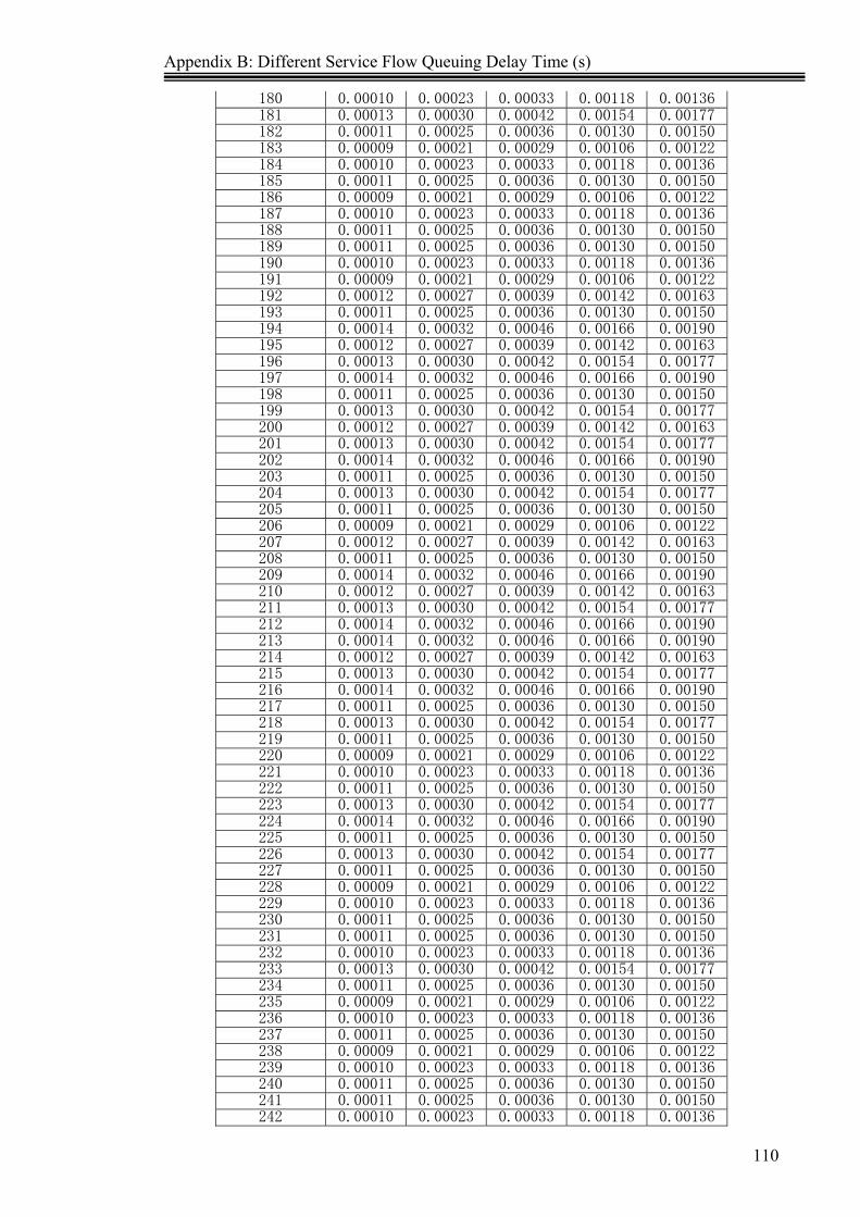
Appendix B: Different Service Flow Queuing Delay Time (s)
110
180 0.00010 0.00023 0.00033 0.00118 0.00136 181 0.00013 0.00030 0.00042 0.00154 0.00177 182 0.00011 0.00025 0.00036 0.00130 0.00150 183 0.00009 0.00021 0.00029 0.00106 0.00122 184 0.00010 0.00023 0.00033 0.00118 0.00136 185 0.00011 0.00025 0.00036 0.00130 0.00150 186 0.00009 0.00021 0.00029 0.00106 0.00122 187 0.00010 0.00023 0.00033 0.00118 0.00136 188 0.00011 0.00025 0.00036 0.00130 0.00150 189 0.00011 0.00025 0.00036 0.00130 0.00150 190 0.00010 0.00023 0.00033 0.00118 0.00136 191 0.00009 0.00021 0.00029 0.00106 0.00122 192 0.00012 0.00027 0.00039 0.00142 0.00163 193 0.00011 0.00025 0.00036 0.00130 0.00150 194 0.00014 0.00032 0.00046 0.00166 0.00190 195 0.00012 0.00027 0.00039 0.00142 0.00163 196 0.00013 0.00030 0.00042 0.00154 0.00177 197 0.00014 0.00032 0.00046 0.00166 0.00190 198 0.00011 0.00025 0.00036 0.00130 0.00150 199 0.00013 0.00030 0.00042 0.00154 0.00177 200 0.00012 0.00027 0.00039 0.00142 0.00163 201 0.00013 0.00030 0.00042 0.00154 0.00177 202 0.00014 0.00032 0.00046 0.00166 0.00190 203 0.00011 0.00025 0.00036 0.00130 0.00150 204 0.00013 0.00030 0.00042 0.00154 0.00177 205 0.00011 0.00025 0.00036 0.00130 0.00150 206 0.00009 0.00021 0.00029 0.00106 0.00122 207 0.00012 0.00027 0.00039 0.00142 0.00163 208 0.00011 0.00025 0.00036 0.00130 0.00150 209 0.00014 0.00032 0.00046 0.00166 0.00190 210 0.00012 0.00027 0.00039 0.00142 0.00163 211 0.00013 0.00030 0.00042 0.00154 0.00177 212 0.00014 0.00032 0.00046 0.00166 0.00190 213 0.00014 0.00032 0.00046 0.00166 0.00190 214 0.00012 0.00027 0.00039 0.00142 0.00163 215 0.00013 0.00030 0.00042 0.00154 0.00177 216 0.00014 0.00032 0.00046 0.00166 0.00190 217 0.00011 0.00025 0.00036 0.00130 0.00150 218 0.00013 0.00030 0.00042 0.00154 0.00177 219 0.00011 0.00025 0.00036 0.00130 0.00150 220 0.00009 0.00021 0.00029 0.00106 0.00122 221 0.00010 0.00023 0.00033 0.00118 0.00136 222 0.00011 0.00025 0.00036 0.00130 0.00150 223 0.00013 0.00030 0.00042 0.00154 0.00177 224 0.00014 0.00032 0.00046 0.00166 0.00190 225 0.00011 0.00025 0.00036 0.00130 0.00150 226 0.00013 0.00030 0.00042 0.00154 0.00177 227 0.00011 0.00025 0.00036 0.00130 0.00150 228 0.00009 0.00021 0.00029 0.00106 0.00122 229 0.00010 0.00023 0.00033 0.00118 0.00136 230 0.00011 0.00025 0.00036 0.00130 0.00150 231 0.00011 0.00025 0.00036 0.00130 0.00150 232 0.00010 0.00023 0.00033 0.00118 0.00136 233 0.00013 0.00030 0.00042 0.00154 0.00177 234 0.00011 0.00025 0.00036 0.00130 0.00150 235 0.00009 0.00021 0.00029 0.00106 0.00122 236 0.00010 0.00023 0.00033 0.00118 0.00136 237 0.00011 0.00025 0.00036 0.00130 0.00150 238 0.00009 0.00021 0.00029 0.00106 0.00122 239 0.00010 0.00023 0.00033 0.00118 0.00136 240 0.00011 0.00025 0.00036 0.00130 0.00150 241 0.00011 0.00025 0.00036 0.00130 0.00150 242 0.00010 0.00023 0.00033 0.00118 0.00136

Appendix B: Different Service Flow Queuing Delay Time (s)
111
243 0.00009 0.00021 0.00029 0.00106 0.00122 244 0.00012 0.00027 0.00039 0.00142 0.00163 245 0.00011 0.00025 0.00036 0.00130 0.00150 246 0.00014 0.00032 0.00046 0.00166 0.00190 247 0.00012 0.00027 0.00039 0.00142 0.00163 248 0.00013 0.00030 0.00042 0.00154 0.00177 249 0.00014 0.00032 0.00046 0.00166 0.00190 250 0.00011 0.00025 0.00036 0.00130 0.00150 251 0.00013 0.00030 0.00042 0.00154 0.00177 252 0.00012 0.00027 0.00039 0.00142 0.00163 253 0.00013 0.00030 0.00042 0.00154 0.00177 254 0.00014 0.00032 0.00046 0.00166 0.00190 255 0.00014 0.00032 0.00046 0.00166 0.00190 256 0.00012 0.00027 0.00039 0.00142 0.00163 257 0.00013 0.00030 0.00042 0.00154 0.00177 258 0.00014 0.00032 0.00046 0.00166 0.00190 259 0.00011 0.00025 0.00036 0.00130 0.00150 260 0.00013 0.00030 0.00042 0.00154 0.00177 261 0.00011 0.00025 0.00036 0.00130 0.00150 262 0.00009 0.00021 0.00029 0.00106 0.00122 263 0.00010 0.00023 0.00033 0.00118 0.00136 264 0.00011 0.00025 0.00036 0.00130 0.00150 265 0.00013 0.00030 0.00042 0.00154 0.00177 266 0.00014 0.00032 0.00046 0.00166 0.00190 267 0.00011 0.00025 0.00036 0.00130 0.00150 268 0.00013 0.00030 0.00042 0.00154 0.00177 269 0.00011 0.00025 0.00036 0.00130 0.00150 270 0.00009 0.00021 0.00029 0.00106 0.00122 271 0.00010 0.00023 0.00033 0.00118 0.00136 272 0.00011 0.00025 0.00036 0.00130 0.00150 273 0.00011 0.00025 0.00036 0.00130 0.00150 274 0.00010 0.00023 0.00033 0.00118 0.00136 275 0.00013 0.00030 0.00042 0.00154 0.00177 276 0.00011 0.00025 0.00036 0.00130 0.00150 277 0.00009 0.00021 0.00029 0.00106 0.00122 278 0.00010 0.00023 0.00033 0.00118 0.00136 279 0.00011 0.00025 0.00036 0.00130 0.00150 280 0.00009 0.00021 0.00029 0.00106 0.00122 281 0.00010 0.00023 0.00033 0.00118 0.00136 282 0.00011 0.00025 0.00036 0.00130 0.00150 283 0.00011 0.00025 0.00036 0.00130 0.00150 284 0.00010 0.00023 0.00033 0.00118 0.00136 285 0.00013 0.00030 0.00042 0.00154 0.00177 286 0.00014 0.00032 0.00046 0.00166 0.00190 287 0.00014 0.00032 0.00046 0.00166 0.00190 288 0.00012 0.00027 0.00039 0.00142 0.00163 289 0.00013 0.00030 0.00042 0.00154 0.00177 290 0.00014 0.00032 0.00046 0.00166 0.00190 291 0.00011 0.00025 0.00036 0.00130 0.00150 292 0.00013 0.00030 0.00042 0.00154 0.00177 293 0.00011 0.00025 0.00036 0.00130 0.00150 294 0.00009 0.00021 0.00029 0.00106 0.00122 295 0.00010 0.00023 0.00033 0.00118 0.00136 296 0.00011 0.00025 0.00036 0.00130 0.00150 297 0.00013 0.00030 0.00042 0.00154 0.00177 298 0.00014 0.00032 0.00046 0.00166 0.00190 299 0.00011 0.00025 0.00036 0.00130 0.00150 300 0.00013 0.00030 0.00042 0.00154 0.00177

Appendix C: DL/UL Peak and Average Throughput
112
Appendix C:
Different Algorithm Average Throughput (Mbps)
ODBA WFQ RED RIO FQ DRR DropTail
386.47 371.28 377.84 378.61 377.84 377.52 377.84
DL Peak Throughput (Mbps)
DL:UL DL
(ODBA) DL
1:0 31.42 31.68
3:1 23.25 23.04
2:1 20.23 20.16
1:1 15.82 15.84
1:2 10.17
1:3 7.42
0:1 0 0
UL Peak Throughput (Mbps)
DL:UL UL(ODBA) UL
1:0 0 0
3:1 4.06 4.03
2:1 5.42 5.04
1:1 8.12 7.06
1:2 10.83
1:3 12.18
0:1 16.25 14.11
References
113
References Ahson, S. Mohammad, I. 2007, ‘WiMAX Technologies performance analysis, and Qos’,
the WiMAX handbook, pages: 296.
Alexander, S, Olli. A,& Juha.K. 2006, ‘Ensuring the QoS requirements in 802.16 Scheduling’ MSWiM, Torremolinos, Malaga, Spain, pp. 108-117.
Andrea, B and Claudio.C, etc, 2007, ‘Bandwidth Allocation with Half-Duplex Stations in IEEE 802.16 Wireless Networks’ , IEEE Transactions on mobile computing, vol. 6. No. 12, pp.1384–1397.
Bader, A.M., etc., 2008, ‘Dynamic Bandwidth Provisioning with Fairness and Revenue Considerations for Broadband Wireless Communication’, IEEE Communication Society, ICC, pages: 5.
Boris, M., 2007, ‘Adaptive resource Allocation For WiMAX’, the 18th Annual IEEE International Symposium on Personal, Indoor and Mobile Radio Communications, pages: 6.
Castrucci, M., Delli Priscoli, F., etc., 2008, ‘Connection Admission Control in WiMAX networks’, IEEE Xplore, pages: 8.
Chen, J.F, Jiao,W.H, etc., 2005, ‘A service Flow Management Strategy for IEEE 802.16 Broadband Wireless Access Systems in TDD Mode’, IEEE, pp. 3422-3426.
Chen, K.C., 2007, ‘Introduction to Mobile WiMAX’, NTUEE Mobile Communications, pages: 9.
Chian, C.H., Liao, W.J., etc. 2009, ‘Adaptive Downlink and Uplink Channel Split Ratio Determination for TCP-Based Best Effort Traffic in TDD-Based WiMAX Networks’, IEEE journal on selected areas in communications, vol. 27, No. 2. pp:182-190.
Chiang, C.H, Liao, W.J & Liu, T. 2007, ‘Adaptive downlink/Uplink bandwidth Allocation in IEEE 802.16(WiMAX) Wireless Networks:A Cross-layer Approach’, IEEE Communications Society, pp. 4771-4775.
Chou, C.H., Kim, K.T., & Youn, H.Y., 2008, ‘Mobile Multi-hop Relay System using AMC for Multicast Broadcast Service over Mobile WiMAX’, IEEE Xplore, pages: 7.
Chou, Z.T, and Lin. Y.H, 2007, ‘Bandwidth Allocation and Recovery for Uplink Access in IEEE 802.16 Broadband Wireless Networks’, IEEE, pp. 1887–1891.
Chu, Q.X., Yang, Y.Y., 2008, ‘3.5/5.5 GHz dual band-notch ultra-wideband antenna’, electronics letters, vol. 44, No. 3. pages:2.
Cristiano, B.B., Eliane, G.C., etc., 2008, ‘Analysis of WiMAX bandwidth allocation mechanism considering physical conditions’, IEEE ISWCS, pp: 643-647.
Du, W.F., etc., 2008, ‘Waiting Queue Based Bandwidth Allocation Architecture for nrtPS and BE Services in IEEE 802.16 PMP Network’, IEEE Xpolre, pp:1-5.
F, M., T, H., 2008, ‘Queuing analysis for dynamic bandwidth allocation in IEEE 802.16 standard’, IEEE Xplore, pp: 616-619.

References
114
Fei, Y. Pujolle, G. 2008, ‘Performance Evaluation of Polling Mechanisms in IEEE 802.16 Networks’, IEICE, page: 5.
Ghaffarian, H., Fathy, M. & Soryani, M., 2008, ‘Channel Access Delay Analysis of IEEE 802-16 Best Effort Services ’, Iran Telecommunication Research Center (ITRC), pages: 5.
Ghazal, S., Mokdad, L. & Jalel, B.O., 2008, ‘Performance Analysis of UGS, rtPS, nrtPS Admission Control in WiMAX Networks’, IEEE Communications Society, ICC, pages: 6.
Haidar, S. Hassan, A. etc., 2007, ‘New Scheduling Architecture for IEEE 802.16 Wireless Metropolitan Area Network’, IEEE Xplore, pp: 203-210.
Hosein, P. 2008, ‘Dynamic Resource Allocation for Uplink Contention Channels in WiMAX’, IEEE Xplore, pages: 6.
Hosein, Parick, 2007, ‘Optimal Allocation of Bandwidth and Power Resources to OFDMA VoIP Channels’, IEEE Xplore, pp. 196-199
Husain, S., Alonso, T., etc., 2008, ‘Remote Device Management of WiMAX Devices in Multi-Mode Multi-Access Environment’, IEEE Xplore, pages: 14.
IEEE Std 802.16-2004, ‘IEEE Standard for Local and Metropolitan Area Networks Part 16: Air Interface for Fixed Broadband Wireless Access Systems’.
IEEE Std. 802.16e-2005, ‘IEEE Standard for Local and Metropolitan Area Networks–Part 1 Amendment for Physical and Medium Access Control Layers for Combined Fixed and Mobile Operation in Licensed Bands and Corrigendu1,’.
Khokhar, K. Salous, S. 2008, ‘Frequency domain simulator for mobile radio channels and for IEEE 802.16-2004 standard using measured channels’, January of IET Communications, Vol. 2, No. 7, pp. 869–877.
Kim, S.K., Yeom, I., 2007, ‘TCP-Aware Uplink Scheduling for IEEE 802.16’, IEEE communications .vol.11, No. 2. pp: 146-148.
Kitti, W, and Aura. G, 2003, ‘IEEE 802.16 Based Last Mile Broadband Wireless Military Networks With Quality of Service Support’, IEEE, pp. 779-784.
Laias, E., Awan, I. & Chan, P.M., 2008, ‘An Integrated Uplink Scheduler In IEEE 802.16’, Second UKSIM European Symposium on Computer Modeling and Simulation, pp:518-523.
Lee, J.H., Kwon, T.Y., etc., 2007, ‘Location Management Area (LMA)-based MBS Handover in Mobile WiMAX Systems’, IEEE Xplore. Page:8.
Lian, C.C., Shao, S.K., etc., 2008, ‘A Newly Proposed Bandwidth Allocation Algorithm for IEEE 802.16 Wireless Access Systems’, IEEE Xplore, pp: 33-39.
Lin, J.C., Chou, C.L., & Liu, C.H.,2008, ‘Performance Evaluation For Scheduling Algorithms In WiMAX Network’, 22nd International Conference on Advanced Information Networking and Applications, pp: 68-74.
Lin, Y.N, Chien, S.H, & Lin,Y.D, 2007, ‘Dynamic Bandwidth Allocation for 802.16e-2005 MAC’, Book Chapter of "Current Technology Developments of WiMax Systems", edited by Maode Ma, to be published by Springer.
Lin, Y.N, Wu. C.W, etc, 2008, ‘A Latency and Modulation Aware Bandwidth Allocation Algorithm for WiMAX Base Stations’, IEEE WCNC, pp. 1408-1413..

References
115
Liu, C.Y., Chen, Y.C., 2008, ‘An Adaptive Bandwidth Request Scheme for QoS Support in WiMAX Polling Services’, the 28th International Conference on Distributed Computing Systems Workshops, pp: 60-65.
Mar, J. Ko, C.C. etc., 2008, ‘The Effect of MIMO Antenna Modes and Vehicle Speed on Channel Throughput of Mobile WiMAX for Multimedia Services’, IEEE 8th International Conference on Computer and Information Technology Workshops, pp: 308-313.
Mario,M. etc., 2007, ‘Optimal Bandwidth Provision at WiMAX MAC service Access Point on Uplink direction’, IEEE Communications Society, ICC.
Markhasin, A., Drozdova, V. 2008, ‘QoS-Oriented Multifunctional Wireless MAC or Remote, Rural, and Difficult for Access Areas ’, IEEE region 8 sibircon, pp: 389-394.
Mobile WiMAX - Part I, 2006, ‘A Technical Overview and Performance Evaluation’, WiMAX Forum.
Mobile WiMAX - Part II, 2006, ‘ A Comparative Analysis’, WiMAX Forum.
Moon, B.K., Mo, J.H., 2008, ‘Optimizing Uplink TCP-ACK Transmission in WiMAX OFDMA Systems’, IEEE communications letters, vol.12, No. 4, pp: 256-257.
Shartri, B. Imeri, I. & maraj, A., 2008, ‘Broadband Wireless Access (BWA) Implementation in NGN Network’, International Conference on Communication Theory, reliability and Quality of Service, pp:47-52.
Wang, H.T, He, B. etc., 2006, ‘Admission Control and Bandwidth Allocation above Packet Level for IEEE 802.16 Wireless MAN’, IEEE Communications Society, ICPADS.
Wang, S.Y., Lin, C.C, & Chu, H.W.,2008, ‘Improving the Performances of Distributed Coordinated Scheduling in IEEE 802.16 Mesh Networks’, IEEE transactions on vehicular technology, vol. 57, NO. 4, pp: 2531-2547.
Xie, X.J., Chen, H.N., & Wu, H.Y., 2009, ‘Simulation Studies of a Fair and Effective Queueing Algorithm for WiMAX Resource Allocation’, IEEE Xplore, pages: 5.
![IEEE 802.16: WiMAX Overview, WiMAX · PDF filevs. 3G. The common Misconceptions about WiMAX & 3G CDMA are [5]: 1) Cost . c. ... IEEE 802.16: WiMAX Overview, WiMAX Architecture . Mojtaba](https://static.fdocuments.in/doc/165x107/5a752f217f8b9ad22a8c6f07/ieee-80216-wimax-overview-wimax-architecture-vs-3g-the-common-misconceptions.jpg)