On acoustic cavitation of slightly subcritical bubbles - arXiv · On acoustic cavitation of...
36
arXiv:physics/9911072v1 [physics.flu-dyn] 26 Nov 1999 On acoustic cavitation of slightly subcritical bubbles Anthony Harkin † Ali Nadim ‡ Tasso J. Kaper † † Department of Mathematics, Boston University, Boston, MA 02215 ‡ Department of Aerospace and Mechanical Engineering, Boston University, Boston, MA 02215 July 24, 1998 Abstract The classical Blake threshold indicates the onset of quasistatic evolution leading to cavitation for gas bubbles in liquids. When the mean pressure in the liquid is reduced to a value below the vapor pressure, the Blake analysis identifies a critical radius which separates quasistatically stable bubbles from those which would cavitate. In this work, we analyze the cavitation threshold for radially symmetric bubbles whose radii are slightly less than the Blake critical radius, in the presence of time-periodic acoustic pressure fields. A distinguished limit equation is derived that predicts the threshold for cavitation for a wide range of liquid viscosities and forcing frequencies. This equation also yields frequency-amplitude response curves. Moreover, for fixed liquid viscosity, our study identifies the frequency that yields the minimal forcing amplitude sufficient to initiate cavitation. Numerical simulations of the full Rayleigh- Plesset equation confirm the accuracy of these predictions. Finally, the implications of these findings for acoustic pressure fields that consist of two frequencies will be discussed. PACS Numbers: Primary 43.25.Yw, Secondary 43.25.Ts, 47.52.+j, 43.25.Rq Keywords: acoustic cavitation, nonlinear oscillations of gas bubbles, dynamic cavitation threshold, periodic pressure fields, quasiperiodic pressure fields, period-doubling.
Transcript of On acoustic cavitation of slightly subcritical bubbles - arXiv · On acoustic cavitation of...

arX
iv:p
hysi
cs/9
9110
72v1
[ph
ysic
s.fl
u-dy
n] 2
6 N
ov 1
999
On acoustic cavitation of slightly subcritical bubbles
Anthony Harkin†
Ali Nadim‡
Tasso J. Kaper†
†Department of Mathematics, Boston University, Boston, MA 02215
‡Department of Aerospace and Mechanical Engineering, Boston University, Boston, MA 02215
July 24, 1998
Abstract
The classical Blake threshold indicates the onset of quasistatic evolution leading to cavitation for gas
bubbles in liquids. When the mean pressure in the liquid is reduced to a value below the vapor pressure,
the Blake analysis identifies a critical radius which separates quasistatically stable bubbles from those
which would cavitate. In this work, we analyze the cavitation threshold for radially symmetric bubbles
whose radii are slightly less than the Blake critical radius, in the presence of time-periodic acoustic
pressure fields. A distinguished limit equation is derived that predicts the threshold for cavitation for a
wide range of liquid viscosities and forcing frequencies. This equation also yields frequency-amplitude
response curves. Moreover, for fixed liquid viscosity, our study identifies the frequency that yields the
minimal forcing amplitude sufficient to initiate cavitation. Numerical simulations of the full Rayleigh-
Plesset equation confirm the accuracy of these predictions. Finally, the implications of these findings for
acoustic pressure fields that consist of two frequencies will be discussed.
PACS Numbers: Primary 43.25.Yw, Secondary 43.25.Ts, 47.52.+j, 43.25.Rq
Keywords: acoustic cavitation, nonlinear oscillations of gas bubbles, dynamic cavitation threshold, periodic
pressure fields, quasiperiodic pressure fields, period-doubling.

I Introduction
The Blake threshold pressure is the standard measure of static acoustic cavitation [2, 1]. Bubbles forced
at pressures exceeding the Blake threshold grow quasistatically without bound. This criterion is especially
important for gas bubbles in liquids when surface tension is the dominant effect, such as submicron air
bubbles in water, where the natural oscillation frequencies are high.
In contrast, when the acoustic pressure fields are not quasistatic, bubbles generally evolve in highly
nonlinear fashions [21, 9, 16, 17]. To begin with, the intrinsic oscillations of spherically symmetric bubbles
in inviscid incompressible liquids are nonlinear [16]. The phase portrait of the Rayleigh-Plesset equation [26,
25, 4], consists of a large region of bounded, stable states centered about the stable equilibrium radius. The
natural oscillation frequencies of these states depend on the initial bubble radius and its radial momentum,
and this family of states limits on a state of infinite period, namely a homoclinic orbit in the phase space,
which acts as a boundary outside of which lie initial conditions corresponding to unstable bubbles. Time-
dependent acoustic pressure fields then interact nonlinearly with both the periodic orbits and the homoclinic
orbit. In particular, they can act to break the homoclinic orbit, permitting initially stable bubbles to leave
the stable region and grow without bound. These interactions have been studied from many points of
view: experimentally, numerically, and analytically via perturbation theory and techniques from dynamical
systems.
In [26], the transition between regular and chaotic oscillations, as well as the onset of rapid radial growth,
is studied for spherical gas bubbles in time-dependent pressure fields. There, Melnikov theory is applied to
the periodically- and quasiperiodically-forced Rayleigh-Plesset equation for bubbles containing an isothermal
gas. One of the principal findings is that, when the acoustic pressure field is quasiperiodic in time with two
or more frequencies, the transition to chaos and the threshold for rapid growth occur at lower amplitudes of
the acoustic pressure field than in the case of single-frequency forcing. Their work was motivated in turn by
that in [13], where Melnikov theory was used to study the time-dependent shape changes of gas bubbles in
time-periodic axisymmetric strain fields.
The work in [25] identifies a rich bifurcation superstructure for radial oscillations for bubbles in time-
periodic acoustic pressure fields. Techniques from perturbation theory and dynamical systems are used to
analyze resonant subharmonics, period-doubling bifurcation sequences, the disappearance of strange attrac-
tors, and transient chaos in the Rayleigh-Plesset equation with small-amplitude liquid viscosity and isentropic
gas. The analysis in [25] complements the experiments of [8] and the experiments and numerical simulations
of [14, 15, 20]. Analyzing subharmonics, these works quantify the impact of increasing the amplitude of the
acoustic pressure field on the frequency-response curves.
Other works examining the threshold for acoustic cavitation in time-dependent pressure fields have fo-
cused on the case of a step change in pressure. In [4], the response of a gas bubble to such a step change in
pressure is analyzed by numerical and Melnikov perturbation techniques to find a correlation between the
cavitation pressure and the viscosity of the liquid. One of the principal findings is that the cavitation pres-
sure scales as the one-fifth power of the liquid viscosity. A general method to compute the critical conditions
for an instantaneous pressure step is also given in [7]. The results extend numerical simulations of [19] and
2

experimental findings of [24], and apply for any value of the polytropic gas exponent.
The goal of the present article is to apply similar perturbation methods and techniques from the theory of
nonlinear dynamical systems to refine the Blake cavitation threshold for isothermal bubbles whose radii are
slightly smaller than the critical Blake radius and whose motions are not quasistatic. Specifically, we suppose
these bubbles are subjected to time-periodic acoustic pressure fields and, by reducing the Rayleigh-Plesset
equations to a simpler distinguished limit equation, we obtain the dynamic cavitation threshold for these
subcritical bubbles.
The paper is organized as follows. In the remainder of this section, the standard Blake cavitation
threshold is briefly reviewed. This also allows us to identify the critical radius which separates stable and
unstable bubbles that are in equilibrium. In section II, the distinguished limit (or normal form) equation of
motion for subcritical bubbles (i.e., those whose radii is slightly smaller than the critical value) is obtained
from the Rayleigh-Plesset equation. This necessitates identifying the natural timescale of oscillation of
such subcritical bubbles which happens to depend upon how close they are to the critical size. We begin
section III by defining a simple criterion for determining when cavitation has occurred. We then analyze
the normal form equation and determine the cavitation threshold for a specific value of the acoustic forcing
frequency (at which the corresponding linear undamped system would resonate). This pressure threshold is
then compared to numerical simulations of the full Rayleigh-Plesset equation and the good agreement found
between the two is demonstrated. The self-consistency of the distinguished limit equation is further discussed
in that section. Section IV generalizes the results to include arbitrary acoustic forcing frequencies. Acoustic
forcing frequencies which facilitate cavitation using the least forcing pressure are determined. An unusual
dependence of the threshold pressure on forcing frequency is discovered and explained by analyzing the
“slowly-varying” phase-plane of the dynamical system. At the end of section IV, our choice of a cavitation
criterion is discussed in the setting of a Melnikov analysis. In section V we extend the cavitation results to
the case of an oscillating subcritical bubble that is driven simultaneously at two different frequencies. We
recap the paper in section VI by highlighting the main results and discussing their applicability. Lastly, we
conclude the paper with an appendix which qualitatively discusses the relation of our results to some recent
experimental findings.
I.1 Blake threshold pressure
To facilitate the development of subsequent sections we first briefly review the derivation of the Blake
threshold [17]. At equilibrium, the pressure, pB, inside a spherical bubble of radius R is related to the
pressure, pL, of the outside liquid through the normal stress balance across the surface:
pB = pL +2σ
R. (1)
The pressure inside the bubble consists of gas pressure and vapor pressure, pB = pg + pv, where the vapor
pressure pv is taken to be constant — pv depends primarily on the temperature of the liquid — and the
pressure of the gas is assumed to be given by the equation of state:
pg = pg0
(
R0
R
)3γ
, (2)
3

with γ the polytropic index of the gas. For isothermal conditions γ = 1, whereas for adiabatic ones, γ is the
ratio of constant-pressure to constant-volume heat capacities. At equilibrium, the bubble has radius R0, the
gas has pressure pg0and the static pressure of the liquid is taken to be p∞0 . Thus, the equilibrium pressure
of the gas in the bubble is given by
pg0= p∞
0− pv +
2σ
R0
.
Upon substituting this result into (2) we get the following expression for the pressure of the gas inside the
bubble as a function of the bubble radius:
pg =
(
p∞0 − pv +2σ
R0
)(
R0
R
)3γ
. (3)
Upon combining equations (1) and (3), we find
pL =
(
p∞0 − pv +2σ
R0
)(
R0
R
)3γ
+ pv − 2σ
R. (4)
Equation (4) governs the change in the radius of a bubble in response to quasistatic changes in the liquid
pressure pL. More precisely, by “quasistatic” we mean that the liquid pressure changes slowly and uniformly
with inertial and viscous effects remaining negligible during expansion or contraction of the bubble. For very
small (sub-micron) bubbles, surface tension is the dominant effect. Furthermore, typical acoustic forcing
frequencies are much smaller than the resonance frequencies of such tiny bubbles. In this case, the pressure
in the liquid changes very slowly and uniformly compared to the natural timescale of the bubble.
For very small bubbles, the Peclet number for heat transfer within the bubble — defined as R20ω/α, with
ω the bubble natural frequency (see subsection II.1) and α the thermal diffusivity of the gas — is small,
and due to the rapidity of thermal conduction over such small length scales, the bubble may be regarded as
isothermal. We therefore let γ = 1 for an isothermal bubble and define
G =
(
p∞0
− pv +2σ
R0
)
R3
0.
Then equation (4) becomes
pL = pv +G
R3− 2σ
R. (5)
The right-hand side of this equation is plotted in figure 1 (solid curve), which shows a minimum value at a
critical radius labeled Rcrit.
Obviously, if the liquid pressure is lowered to a value below the corresponding critical pressure pLcrit, no
equilibrium radius exists. For values of pL which are above the critical value but below the vapor pressure pv,
equation (5) yields two possible solutions for the radius R. Bubbles whose radii are less than the Blake radius,
Rcrit, are stable to small disturbances, whereas bubbles with R > Rcrit are unstable to small disturbances.
The Blake radius itself can be obtained by finding the minimum of the right-hand side of (5) for R > 0.
This yields the critical Blake radius
Rcrit =
(
3G
2σ
)1/2
, (6)
at which the corresponding critical liquid pressure is
pLcrit= pv −
(
32σ3
27G
)1/2
. (7)
4
By combining the last two equations, it is also possible to express the Blake radius in the form:
Rcrit =4σ
3(pv − pLcrit)
,
relating the critical bubble radius to the critical pressure in the liquid. Bubbles whose radii are smaller than
Rcrit are quasistatically stable, while bigger ones are unstable.
To obtain the standard Blake pressure we assume that pv can be ignored and recall that surface tension
dominates in the quasistatic regime which amounts to p∞0
≪ 2σ/R0. Under these approximations, G ≈ 2σR20
and the Blake threshold pressure is conventionally defined as
pBlake ≡ p∞0
− pLcrit
≈ p∞0 + 0.77σ
R0
.
In the quasistatic regime where the Blake threshold is valid, pBlake is the amplitude of the low-frequency
acoustic pressure beyond which acoustic forcing at higher pressures is sure to cause cavitation. When
the pressure changes felt by the bubble are no longer quasistatic, a more detailed analysis taking into
consideration the bubble dynamics and acoustic forcing frequency must be performed to determine the
cavitation threshold. This is the type of analysis we undertake in this contribution.
II The distinguished limit equation
II.1 Derivation
To make progress analytically, we focus our attention on “subcritical” bubbles whose radii are only slightly
smaller than the Blake radius at a given liquid pressure below the vapor pressure. We thus define a small
parameter ǫ > 0 by
ǫ = 2
[
1 − R0
Rcrit
]
, (8)
which measures how close the equilibrium bubble radius R0 is to the critical value Rcrit. The value of the
mean pressure in the liquid, corresponding to the equilibrium radius R0, can also be found from equation
(5) to be
p∞0
− pv =2σ
3R0
[(1 − ǫ
2)−2 − 3] = − 4σ
3R0
[1 − 1
2ǫ − 3
8ǫ2 + O(ǫ3)] . (9)
The liquid pressure p∞0
and the critical pressure pLcritdiffer only by an O(ǫ2) amount.
It turns out that the characteristic time scale for the natural response of such subcritical bubbles also
depends on the small parameter ǫ. This timescale for small amplitude oscillations of a spherical bubble is
obtained by linearizing the isothermal, unforced Rayleigh-Plesset equation [21]
ρ
[
RR +3
2R2
]
=
(
p∞0 − pv +2σ
R0
)(
R0
R
)3
+ pv − 2σ
R− p∞0 , (10)
where the density of the liquid is given by ρ and viscosity has been neglected. Specifically, we substitute
R = R0(1 + x) into (10) and keep terms linear in x to get:
x +
[
4σ
ρR30
+3(p∞
0− pv)
ρR20
]
x = 0. (11)
5
Solutions to (11), representing small amplitude oscillations about equilibrium, are therefore x = x0 cos(ωt+φ)
with the angular frequency given by
ω =
[
4σ
ρR30
+3(p∞0 − pv)
ρR20
]1/2
. (12)
We now use ω to define a nondimensional time variable: τ = ωt. We are interested in analyzing stability for
values of (R0, p∞
0 ) near (Rcrit, pLcrit). Hence, upon recalling (6), (7) and (8), we see that:
τ =
[
2σ
ρR30
(
2
[
1 − R0
Rcrit
])]1/2
t =
[
2σǫ
ρR30
]1/2
t .
We note that as ǫ tends to zero, the timescale for bubble oscillations (the reciprocal of the factor multiplying
t in the last equation) increases as ǫ−1/2.
Having determined the proper scaling for the time variable for slightly subcritical bubbles, we can now
find the distinguished limit (or normal form) equation for such bubbles in a time-periodic pressure field. We
start with the isothermal, viscous Rayleigh-Plesset equation [21]:
ρ
[
RR +3
2R2
]
+ 4µR
R=
(
p∞0
− pv +2σ
R0
)(
R0
R
)3
+ pv − 2σ
R− p∞
0+ pA sin(Ωt). (13)
The amplitude and frequency of the applied acoustic forcing are given by pA and Ω, respectively, and
µ represents the viscosity of the fluid. Here, the far-field pressure in the liquid has been taken to be
p∞0 − pA sin(Ωt), with p∞0 given by equation (9). Setting R(t) = R0(1 + ǫx(τ)), with ǫ the same small
parameter introduced above, we obtain at order ǫ2 (noting that all of the O(1) and O(ǫ) terms cancel):
x + 2ζx + x − x2 = A sin(Ω∗τ), (14)
where
ζ =
(
2µ2
ǫσρR0
)1/2
, A =pAR0
2σǫ2, Ω∗ = Ω
(
ρR30
2σǫ
)1/2
. (15)
In equation (14), each overdot represents a derivative with respect to τ .
It is implicit in the above scaling that ζ, A, and Ω∗ are nondimensional and O(1) with respect to ǫ. To see
that this is reasonable, consider an air bubble in water with ρ = 998 kg/m3, µ = 0.001 kg/m·s, σ = 0.0725
N/m. If we specify ǫ = 0.1 and take a modest equilibrium radius of R0 = 2 × 10⁻⁶ m then ζ = 0.38. Our
analysis of (14) in subsequent sections will concentrate primarily on values of ζ in the range 0 ≤ ζ ≤ 0.4.
The parameters A and Ω∗ are related to the forcing conditions, and their magnitudes can be made order
unity by choosing appropriate forcing parameters pA and Ω. As an example, if we again choose R0 to
equal 2 microns, then Ω∗ = (2.35 × 10⁻⁷s)Ω/√
ǫ. Moreover, setting ǫ = 0.05 gives Ω∗ = (1.05 × 10⁻⁶s)Ω.
Hence, the dimensionless parameter Ω∗ is O(1) when Ω is in the megahertz range, and this is precisely
the frequency range we are interested in exploring. Similarly, with R0 and σ chosen as above, we find
A = (1.38 × 10⁻⁵m·s2/kg)pA/ǫ2 and thereby we see that if ǫ = 0.1 then pA can become on the order of
103Pa. More data will be presented later, in figure 9, showing typical forcing pressures.
II.2 Interpretation
In the laboratory one can create a subcritical bubble by subjecting the liquid to a low-frequency transducer
whose effect is to lower the ambient pressure below the vapor pressure. Then a second transducer of high
6
frequency (high relative to the slow transducer) will give rise to the forcing term on the right hand side
of (14). The low-frequency transducer periodically increases and decreases the pressure in the liquid (and
shrinks and expands the bubble, which follows this pressure field quasistatically). When the peak negative
pressure is reached (and the bubble has expanded to its maximum size), we can imagine that state as the
new equilibrium state, and at that point bring in the effects of the sound from the second transducer. This
second field can then possibly make the bubble, which had already grown to some large size (but still smaller
than the critical radius), become unstable. This would all happen very fast compared to the time scale of
the original slow transducer, so the pressure field contributed by the original transducer remains near its
most negative value throughout. The stability response of the bubble to the high frequency component of
the pressure field is the subject of the rest of this work.
III Acoustic forcing thresholds (Ω∗ = 1)
The value of Ω∗ = 1 corresponds to the forcing frequency at which the linear and undamped counterpart
of (14) would resonate. We therefore choose this value of the forcing frequency as a starting point and
perform a detailed analysis of the dynamics inherent in the distinguished limit equation at this value of Ω∗.
We caution, however, that, as with most forced, damped nonlinear oscillators, the largest resonant response
occurs away from the resonance frequency of the linear oscillator. We use Ω∗ = 1 mainly as a starting point
for the analysis, and the dynamics observed for a range of other Ω∗ values is reported in section IV.
Some special cases of (14) can be readily analyzed when Ω∗ = 1. In the absence of forcing, i.e., when
A = 0, the phase portraits of (14) with ζ ≥ 0 are shown in figure 2. With no damping (figure 2a), the phase
plane has a saddle point at (1,0) and a center at (0,0). The latter represents the equilibrium radius of the
bubble which, when infinitesimally perturbed, results in simple harmonic oscillations of the bubble about
that equilibrium. The saddle point at (1,0) represents the effects of the second nearby root of the equation
(5) which is an unstable equilibrium radius. When damping is added (figure 2b), the saddle point remains
a saddle, but the center at (0,0) becomes a stable spiral, attracting a well-defined region of the phase space
towards itself. In the presence of weak forcing (small A) but with no damping (ζ = 0), the behavior of (14)
can be seen in a Poincare section shown in figure 3.
III.1 Phase plane criterion for acoustic cavitation
To determine when a slightly subcritical bubble becomes unstable we choose a simple criterion based upon
the phase portrait of the distinguished limit equation (14). For a given ζ, there exists a threshold value,
Aesc, of A such that the trajectory through the origin (0,0) grows without bound for A > Aesc, whereas that
trajectory stays bounded for A < Aesc. A stable subcritical bubble becomes unstable as A increases past
Aesc. Thus there is a stability curve in the (A, ζ)-plane separating the regions of this parameter space for
which the trajectory starting at the origin in the phase-plane either escapes to infinity or remains bounded.
Numerically, many such threshold ζ, Aesc pairs (represented by the open circles in figure 4) were found
with Ω∗ = 1. The data are seen empirically to be well fitted by a least-squares straight line, given by
Aesc = 1.356ζ + 0.058.
7

For practical experimental purposes a linear regression curve based upon our escape criterion should
provide a useful cavitation threshold for the acoustic pressure in the following dimensional form:
pA > 3.835ǫ3/2σ1/2µ
ρ1/2R3/2
0
+ 0.116ǫ2σ
R0
. (16)
Here, ǫ is given by equation (8) and is itself a function of the equilibrium radius R0, surface tension σ and
the pressure differential p∞0
− pv.
III.2 Period doubling in the distinguished limit equation
It so happens that the stability curve for the trajectory of the origin can also be interpreted in terms of the
period doubling route to chaos for the escape oscillator (14). In other words, the value of Aesc happens to
be very near the limiting value at which the oscillations become chaotic, just before getting unbounded. For
a fixed value of ζ > 0 and a small enough A, the trajectory of the origin will settle upon a stable limit cycle
in the phase plane. As A is increased gradually, the period of this stable limit cycle undergoes a doubling
cascade as shown in figure 5 for a fixed value of ζ = 0.35. The period doubling sequence will continue as A
is increased until the trajectory of the origin eventually becomes chaotic, but still remains bounded. Finally,
at a threshold value of A the trajectory of the origin will escape to infinity. This is the value of A that is
given by the open circles on the stability diagram (figure 4). A typical bifurcation diagram for the escape
oscillator (14) with ζ > 0 is shown in figure 6 in which ζ = 0.375.
III.3 Robustness of the simple cavitation criterion
In this subsection we justify defining a cavitation criterion based upon the fate of a single initial condition.
In all simulations with ζ > 0, there is a large region of initial conditions whose fate (escaping or staying
bounded) is the same as that of the origin (figure 7). In fact, when the trajectory through the origin stays
bounded it is clear from the simulations that the origin lies in the basin of attraction of a bounded, attracting
periodic orbit, and points in a large region around it all lie in the basin of attraction of the same orbit. The
trajectories through all points in that basin remain bounded. Then, as the forcing amplitude is increased the
attractor is observed to undergo a sequence of period-doubling bifurcations, and this sequence culminates at
the forcing magnitude when the origin and other initial conditions in a large region about it escape, because
there is no longer a bounded attracting orbit in whose basin of attraction they lie.
III.4 Comparison with full Rayleigh-Plesset simulations
The stability threshold predicted by equation (16) can be compared to data obtained from simulating the
Rayleigh-Plesset equation (13) directly. For small values of ǫ, figure 8 shows the resulting good agreement.
The following is a brief description of how the simulations were carried out. The material parameters
used to produce figure 8 were ρ = 998 kg/m3, µ = 0.001 kg/m·s, and σ = 0.0725 N/m. Four values of ǫ were
chosen, ǫ = 0.01, 0.05, 0.1, and 0.2. For each fixed value of ǫ and for a selected set of values of ζ ranging
from 0 to 0.4, the parameters R0, Rcrit, (pv − p∞0 ), and Ω were calculated successively using the formulae:
8

R0 = 2µ2/(ζ2ǫρσ), Rcrit = R0/(1− ǫ/2), pv −p∞0 = (2σ/R0)[1− (1/3)/(1− ǫ/2)2], and Ω = [(2σǫ)/(ρR30)]
1/2.
(Note that this succession of computations is done for each chosen value of ζ in each of the four plots.)
Having obtained the dimensional parameters required for the simulation of the full Rayleigh-Plesset
equations corresponding to a given (ǫ, ζ) pair, we used a bisection procedure to determine ARPesc , the threshold
value of A separating bounded and unbounded bubble trajectories. The bisection procedure was initiated by
choosing a value of A close to the linear regression line. For this choice of A, the dimensional pressure, pA,
was calculated using the middle equation in (15). Then, the initial condition R(0) = R0 and R(0) = 0 was
integrated forward in time using an implicit [22] fourth-order Runge-Kutta scheme. The adaptive, implicit
scheme we used offers an accurate and stable means to integrate the governing equations. The time steps
are large in those intervals in which the bubble radius does not change rapidly, and they are extremely short
for the intervals where R or R is large (see for example figure 4.7 on page 309 of [17]). If the bubble radius
remained bounded during the simulation, then the value of A was increased slightly, a new pA was calculated,
and a new simulation was begun. If, on the other hand, the bubble radius became unbounded during the
simulation, then the value of A was slightly decreased and a new simulation was initiated. Continuing with
this bisection of A, the threshold value, ARPesc , where the bubble first becomes unstable was determined.
The dimensional counterpart (pA-versus-R0) to figure 8 is shown in figure 9 along with the dimensional
stability curve given by equation (16). Note that for a given parameter ǫ, the relationship which defines the
dimensionless damping parameter ζ, i.e., R0 = 2µ2/(ζ2ǫρσ), can be thought of as defining the bubble radius
R0. That is, for a given liquid viscosity µ and with all other physical parameters being constant, ζ can only
change by varying the equilibrium radius R0. As such, the dimensionless A-versus-ζ curves can be put in
terms of the dimensional pA-versus-R0 curves, drawn in figure 9.
To show the way in which the bubble radius actually becomes unbounded in the full Rayleigh-Plesset
simulations, figure 10 provides the radius-versus-time plots for three typical simulations with the same value
of ζ = 0.3, where time is nondimensional. In this case, ARPesc ≈ 0.51. The top two curves are obtained
for values of A of 0.3 and 0.5, respectively. They show stable oscillations although a period-doubling can
be seen to have occurred in going from one to the other. The bottom figure corresponds to A = 0.53 and
shows that the bubble radius is becoming unbounded. The corresponding dimensional parameters for the
Rayleigh-Plesset simulations are given in the figure caption.
III.5 Consistency of the distinguished limit equation
In this subsection, we argue, a posteriori, that it is self-consistent to use the escape oscillator as the dis-
tinguished limit equation (14) for the full Rayleigh-Plesset (13), i.e., we show that the higher-order terms
encountered during the change of variables from R to x may be neglected in a consistent fashion.
Recall that, in the derivation of the escape oscillator, all of the O(1) and O(ǫ) terms dropped out, and
the ordinary differential equation (14) was obtained by equating the terms of O(ǫ2). The remaining terms
are of O(ǫ3) and higher. To be precise, at O(ǫ3), we find on the left-hand side:
xx − 2ζxx +3
2x2,
9

and on the right-hand side:
−3
4x + 2x2 − 20
3x3.
Moreover, we note that, for i ≥ 4, all terms of O(ǫi) on the left-hand side are of the form xi−2x, while all
terms of O(ǫi) on the right-hand side are polynomials in x.
We already know that, for trajectories of the escape oscillator that remain bounded, the x and x vari-
ables stay O(1). Hence, all of the higher-order terms remain higher-order for these trajectories. Next, for
trajectories that eventually escape (i.e., those whose x-coordinate exceeds some large cut-off at some finite
time), we know that x and x are bounded until that time and afterwards they grow without bound. The
fact that then R also grows without bound for these trajectories (due to the change of variables that defines
x) is consistent with the dynamics of the full Rayleigh-Plesset equation.
Potential trouble could arise with trajectories for which x becomes negative and large in magnitude,
e.g., when x ∼ −1/ǫ the coefficient of x vanishes. (This corresponds to small R.) A glance at the Poincare
map for the escape oscillator reveals, however, that trajectories which have x ∼ −1/ǫ at some time τ can
never have x(τ) and x(τ) of O(1) simultaneously, for any τ . Hence, these trajectories are not in the regime
of interest, neither for the escape oscillator nor for the full Rayleigh-Plesset equation. This completes the
argument that it is self-consistent to use the escape oscillator for this study.
IV Pressure thresholds for general Ω∗
IV.1 Stability curves for various Ω∗
Until now, we have only examined the case Ω∗ = 1 in the distinguished limit equation (14). In this section
we examine the dependence of the stability threshold on the acoustic frequency, Ω, for subcritical bubbles.
Specifically, for frequencies Ω∗ between 0.1 and 1.1, we performed numerical simulations of the distinguished
limit equation (14) to determine many (ζ, Aesc) pairs. These pairs are plotted in figure 11, and the data
points at each dimensionless frequency Ω∗ are connected by straight lines (in contrast to the least squares
fitting done in subsection III.1).
As in subsection III.1, good agreement between the distinguished limit equation threshold and the full
Rayleigh-Plesset equation is observed for various values of Ω∗; this can been seen in figure 12 which compares
the two results at four different values of Ω∗ given by 0.6, 0.7, 0.8 and 0.9, for a fixed value of ǫ = 0.05.
Various features observed in figure 11, such as the flattening of these curves as Ω∗ decreases, are explained
in the next subsection.
IV.2 Minimum forcing threshold
Suppose that we wish to determine the driving frequency, for a given bubble with an equilibrium radius R0
and a critical radius Rcrit, so that the acoustic forcing amplitude necessary to make the bubble unstable is
minimized. This can be done by choosing in figure 11, the value of Ω∗ for which the corresponding threshold
curve is below all the others for a given ζ. The result of such a procedure is provided in figure 13 as follows.
Figure 13(a) provides the frequency of harmonic forcing at a given value of the damping parameter ζ for
10
which the required amplitude of the acoustic pressure field to create cavitation is the smallest. Figure 13(b)
shows the dimensionless minimum pressure amplitude Aesc corresponding to the value of Ω∗ just presented.
In figure 13(a), for ζ between 0 and 0.225, the frequency curve is nearly a straight line and we fit a linear
regression line to the data in that interval: Ω∗ = −1.12ζ +0.90 for 0 ≤ ζ ≤ 0.225. Correspondingly, in figure
13(b), we see that the minimum pressure curve is also nearly straight for the same interval of ζ values. The
least squares line fitting the data in figure 13(b) is A = 1.03ζ + 0.02 for 0 ≤ ζ ≤ 0.225.
When ζ = 0.225, there is a discontinuity in the frequency curve, as seen in figure 13(a). At the same
value of ζ, the pressure curve levels off to A ≈ 0.25. This can be explained by a brief analysis of the normal
form equation. The key observation will be that, in the escape oscillator with constant forcing (i.e., constant
right-hand side), there is a saddle-node bifurcation when the magnitude of the forcing is 1/4. In order to
carry out this brief analysis, we consider the cases ζ > 0 and ζ = 0 separately, beginning with ζ > 0.
For ζ > 0, the Poincare map of the normal form equation (14) has an asymptotically stable fixed point
(a sink), which corresponds to an attracting periodic orbit for the full normal form equation. Now, during
each period of the external forcing, the location of this periodic orbit in the (x, x)-plane changes. In fact,
for the small values of Ω∗ we are interested in here (Ω∗ ≤ 0.3 approximately), the change in location occurs
slowly, and one can write down a perturbation expansion for its position in powers of the small parameter
Ω∗. The coefficients at each order are functions of the slow time z ≡ Ω∗t. To leading order, i.e., at O(1), the
attracting periodic orbit is located at the point (x(z), 0), where x(z) is the smaller root of x−x2 = A sin(z),
namely
x(z) =1
2− 1
2
√
1 − 4A sin(z).
Therefore, one sees directly that A = 1/4 is a critical value. In particular, if one considers any fixed
value of A < 1/4, then the attracting periodic orbit exists for all time, and the trajectory of our initial
condition (0, 0) will be always be attracted to it. (Note that the viscosity ζ ≥ 0.225 is large enough
so orbits are attracted to the stable periodic orbit at a faster rate than the rate at which the periodic
orbit’s position moves in the (x, x)-plane due to the slow modulation.) However, for any fixed value of
A > 1/4, the function giving x(z) becomes complex after the slow time z reaches a critical value z∗(A),
where A sin(z∗) = 1/4, and where we write z∗(A) since z∗ depends on A. Moreover, x(z) remains complex
in the interval (z∗(A), π − z∗(A)) during which A sin(z) > 1/4. Viewed in terms of the slowly-varying phase
portrait, the slowly-moving sink merges with the slowly-moving saddle in a saddle-node bifurcation when z
reaches z∗(A), and they disappear together for z∗(A) < z < π − z∗(A). Hence, the attracting periodic orbit
no longer exists when z reaches z∗(A), and the trajectory that started at (0, 0) — and that was spiraling in
toward the slowly-moving attracting periodic orbit while z was less than z∗(A) — escapes, because there is
no longer any attractor to which it is drawn.
For the sake of completeness in presenting this analysis, we note that when A = 1/4, then z∗(A) = π/2;
hence, it is precisely near this lowest value of A, namely A = 1/4, that we find the threshold for the acoustic
forcing amplitude, and the escape happens near the slow time z = π/2. Moreover, for values of A > 1/4,
0 < z∗(A) < π/2, and so the escape happens at an earlier time.
Numerically, the minimal frequency Ω∗ appears to be Ω∗ ≈ 0, where Ω∗ = 0.01 is the lowest value for
which we conducted simulations. Moreover, this also explains why, as we see from figure 11 already, the
11
curves are flat with A ≈ 0.25 for Ω∗ ≤ 0.3. This is the range of small values of Ω∗ for which the above
analysis applies.
Next, having analyzed the regime in which ζ > 0, we turn briefly to the case ζ = 0. For small values,
Ω∗ ≤ 0.3, the curves in figure 11 remain flat near A = 0.25 all the way down to ζ = 0. The full normal form
equation with ζ = 0 is a slowly-modulated Hamiltonian system. One can again use the slowly-varying phase
planes as a guide to the analysis (although the periodic orbit is only neutrally stable when ζ = 0 and no
longer attracting as above), and the saddle-node bifurcation in the leading order problem at A sin(z∗) = 1/4
is the main phenomenon responsible for the observation that the threshold forcing amplitude is near 0.25.
(We also note that for a detailed analysis of the trapped orbits, one needs adiabatic separatrix-crossing
theory, see [3], for example, but we shall not need that here.)
Finally, and most importantly, simulations of the full Rayleigh-Plesset equation confirm all the quan-
titative features of this analysis of the normal form equation. The open circles in figure 13 represent the
numerically observed threshold forcing amplitudes, and these circles lie very close to the curves obtained as
predictions from the normal form equation. We attribute this similarity to the fact that the phase portrait
of the isothermal Rayleigh-Plesset equation has the same structure — stable and unstable equilibria, sep-
aratrix bounding the stable oscillations, and a saddle-node bifurcation when the forcing amplitude exceeds
the threshold — as the normal form equation (see [26]).
IV.3 The dimensional form of the minimum forcing threshold
Recall, that for ζ between 0 and 0.225, we fit linear regression lines to portions of figures 13(a) and (b).
Specifically, for figure 13(a) we found that, for a particular choice of ζ, the frequency which yields the smallest
value of Aesc can be expressed as: Ω∗ = −1.12ζ +0.90 for 0 ≤ ζ ≤ 0.225. And for figure 13(b) we found that
the stability boundary for the minimum forcing is given by,
A =
1.03ζ + 0.02 for 0 ≤ ζ ≤ 0.225
0.25 for 0.225 ≤ ζ ≤ 0.4 .(17)
Using the definitions of ζ, A and Ω∗ as given by (15), the “optimal” acoustic frequency to cause cavitation
of a subcritical bubble is given in dimensional form by
Ω = −2.24µ
ρR20
+ 1.27ǫ1/2σ1/2
ρ1/2R3/2
0
for 0 ≤(
2µ2
σǫρR0
)1/2
≤ 0.225 .
Correspondingly, the minimum acoustic pressure threshold is
pA >
2.91 ǫ3/2σ1/2µ
ρ1/2R3/2
0
+ 0.04 ǫ2σR0
for 0 ≤(
2µ2
ǫσρR0
)1/2
≤ 0.225
ǫ2σ2R0
for 0.225 ≤(
2µ2
ǫσρR0
)1/2
≤ 0.4 .
IV.4 A lower bound for Aesc via Melnikov analysis
The distinguished limit equation (14) can be written as the perturbed system
x = f(x) + ǫg(x, τ)
12

where, x = (x, y), f(x, y) = (y, x2 − x) and g(x, y, τ) =(
0, A sin(Ω∗τ) − 2ζy)
with A = ǫA, ζ = ǫζ.
When ǫ = 0 the system has a center at (0,0) and a saddle point at (1,0). The homoclinic orbit to the
unperturbed saddle is given by γ0(τ) = (x(τ), y(τ)) where x(τ) = −(1/2) + (3/2) tanh2(τ/2) and y(τ) =
(3/2) tanh(τ/2)sech2(τ/2). Following [12], the Melnikov function takes the form
M(τ0) =
∫
∞
−∞
f(γ0(τ)) ∧ g(γ0(τ), τ + τ0) dτ
=3
2A
∫
∞
−∞
sin[Ω∗(τ + τ0)] tanh(τ
2
)
sech2
(τ
2
)
dτ
− 9
2ζ
∫
∞
−∞
tanh2
(τ
2
)
sech4
(τ
2
)
dτ.
The first integral can be done with a residue calculation, and the second integral is evaluated in a straight-
forward manner, resulting in:
M(τ0) = −[
6π(Ω∗)2 cos(Ω∗τ0)
sinh(πΩ∗)
]
A − 12
5ζ.
The Melnikov function has simple zeros when A > Ah.tan., where
Ah.tan. =
(
2 sinh(πΩ∗)
5π(Ω∗)2
)
ζ. (18)
Hence the stable and unstable manifolds of the perturbed saddle point intersect transversely for all sufficiently
small ǫ 6= 0 when A > Ah.tan. [12]. The resulting chaotic dynamics is evident in figure 5, for example. Since
homoclinic tangency must occur before the trajectory through the origin can escape, Ah.tan. may be viewed
as a precursor to Aesc. Figure 14 demonstrates that, for small enough ǫ, equation (18) provides a lower
bound for the stability curves seen in figure 11.
The reason why Melnikov analysis yields a lower bound for the cavitation threshold relates to how
deeply the stable and unstable manifolds of the saddle fixed point of the Poincare map for equation (14)
penetrate into the region bounded by the separatrix in the A, ζ = 0 case. For sufficiently small values of ǫ,
long segments of the perturbed local stable and unstable manifolds will stay O(ǫ) close to the unperturbed
homoclinic orbit. However, as ǫ grows (and one gets out of the regime in which the asymptotic Melnikov
theory strictly applies), these local manifolds will penetrate more deeply into the region bounded by the
separatrix in the A, ζ = 0 case. In fact, there is a sizable gap in the parameter space between the homoclinic
tangency values and the escape values corresponding to our cavitation criteria, i.e., when the trajectory
through the origin grows without bound. There is a similar gap when other initial conditions are chosen.
The Melnikov function was also calculated in [27]. There, a detailed analysis of escape from a cubic
potential is described and the fractal basin boundaries and occurrence of homoclinic tangencies are given.
We also refer the reader to [11] in which a closely related second order, damped and driven oscillator with
quadratic nonlinearity is studied using both homoclinic Melnikov theory, as was done here, and subharmonic
Melnikov theory. The existence of periodic orbits is demonstrated there, and period doubling bifurcations
of these periodic orbits are examined. Their equation arises from the study of travelling waves in a forced,
damped KdV equation.
13

V Pressure fields with two fast frequencies
In this section, we consider what happens to the cavitation threshold if two fast frequency components
are present in the acoustic pressure field, and the slow transducer, which lowers the ambient pressure and
whose effect is quasistatic, is also still present. In figure 15, we show the results from simulations with
quasiperiodic pressure fields. These were obtained from simulations of (14) with the forcing replaced by
(A/2)(sin(Ω∗
1τ) + sin(Ω∗
2τ)), and a wide range of values for Ω∗
1and Ω∗
2. For a fixed value of ζ = 0.25, the
cavitation surface shown in the figure was plotted by computing the triples (Ω∗
1, Ω∗
2, Aesc).
We note that in figure 15, the intersection of the cavitation surface and the vertical plane given by
Ω∗
1= Ω∗
2represents cavitation thresholds for acoustic forcing of the form A sin(Ω∗τ) (i.e., a single fast
frequency component and a quasistatic component). Furthermore, we see that the global minimum of the
cavitation surface lies along the line Ω∗
1= Ω∗
2. Hence, for A/2 as our particular choice of quasiperiodic
forcing coefficient, the addition of a second fast frequency component in the pressure field does not lower
the cavitation threshold beyond that of the single fast frequency case.
VI Discussion
A distinguished limit equation has been derived which is suitable for use in determining cavitation events of
slightly subcritical bubbles. This “normal form” equation allows us to study cavitation thresholds for a range
of acoustic forcing frequencies. For Ω∗ = 1, we find an explicit expression for the cavitation threshold via
linear regression, since the simulation data reveal an approximate linear dependence of the nondimensional
threshold amplitude, A, on the nondimensional liquid viscosity, ζ. When converted to dimensional form, this
linear expression translates into a nonlinear dependence, cf. equation (16), on the material parameters. In
all of our simulations, the acoustic threshold amplitude coincides with the amplitudes at which the cascades
of period-doubling subharmonics terminate.
Particular attention has also been paid to calculating the frequency, Ω∗, at which a given subcritical
bubble will most easily cavitate. Expression (17) for the corresponding minimum threshold amplitude A
grows linearly in ζ for ζ < 0.225 until the critical amplitude A = 1/4 is reached, and the threshold amplitude
stays constant at A ≈ 1/4 for larger ζ. For these larger values of ζ > 0.225, the “optimal” frequency is
essentially zero, as we showed by doing a slowly-varying phase portrait analysis and exploiting the fact that
the normal form equation undergoes a saddle-node bifurcation at A = 1/4 in which the entire region of
bounded stable orbits vanishes. The full Rayleigh-Plesset equation undergoes a similar bifurcation at forcing
amplitudes very near A = 1/4 for sufficiently small ǫ. Overall, the results from the normal form equation
are in excellent agreement with those of the full Rayleigh-Plesset equation, and this may be attributed to
the high level of similarity between the phase-space structures of both equations.
In view of the findings in [26], we may draw an additional conclusion from the present work. In a certain
sense, we have extended the finding of lowered transition amplitudes reported in [26] to the limiting case
of one low frequency and one fast frequency. We find that if a low frequency transducer prepares a bubble
to become slightly subcritical, then the presence of a high frequency transducer can lower the cavitation
14
threshold of the bubble below the Blake threshold.
Our results on the optimum forcing frequency and minimum pressure threshold to cavitate a subcritical
bubble may also be useful in fine-tuning experimental work on single-bubble sonoluminescence (SBSL). In
SBSL [10, 6, 23], a single bubble is acoustically forced to undergo repeated cavitation/collapse cycles, in
each of which a short-lived flash of light is produced. While the process through which a collapsing bubble
emits light is very complex and involves many nonlinear phenomena, the possibility of better control over
cavitation and collapse, e.g., through the use of multiple-frequency forcing, can perhaps be investigated using
the type of analysis presented in this paper.
Acknowledgments — We are grateful to Professor S. Madanshetty for many helpful discussions. The
authors would also like to thank the referees for their comments. This research was made possible by Group
Infrastructure Grant DMS-9631755 from the National Science Foundation. A.H. gratefully acknowledges
financial support from the National Science Foundation via this grant. T.K. gratefully acknowledges support
from the Alfred P. Sloan Foundation in the form of a Sloan Research Fellowship.
Appendix: Coaxing experiments in acoustic microcavitation
To illustrate one application of our results, we now briefly consider the experimental findings of [18] on
so-called “coaxing” of acoustic microcavitation. In these experiments, smooth submicrometer spheres were
added to clean water and were found to facilitate the nucleation of cavitation events (i.e. reduce the cavitation
threshold) when a high-frequency transducer (originally aimed as a detector) was turned on at a relatively
low pressure amplitude. Specifically, the main cavitation transducer was operating at a frequency of 0.75
MHz, while the active detector had a frequency of 30 MHz. In a typical experiment, with 0.984-micron
spheres added to clean water, the cavitation threshold in the absence of the active detector was found to be
about 15 bar peak negative. When the active detector was turned on, producing a minimum pressure of only
0.5 bar peak negative by itself, it caused the cavitation threshold of the main transducer to be reduced from
15 to 7 bar peak negative. The polystyrene latex spheres were observed under scanning electron microscopes
and their surface was determined to be smooth to about 50 nanometers. It was thus thought that any gas
pockets which were trapped on their surface due to incomplete wetting and which served as nucleation sites
for cavitation, were smaller in size than this length. In [18], it is conjectured that the extremely high fluid
accelerations created by the high-frequency active detector, coupled with the density mismatch between the
gas and the liquid, caused these gas pockets to accumulate on the surface of the spheres and form much
larger “gas caps” (on the order of the particle size), which then cavitated at the lower threshold. Here we
attempt to provide an alternative explanation for the observed lowering of the threshold in the presence of
the active detector.
To effect our estimates, we shall use the same physical parameters as earlier: µ = 0.001 kg/m·s, ρ = 0.998
kg/m3 and σ = 0.0725 N/m. We also ignore the vapor pressure of the liquid at room temperature. Note also
that 1 bar=105 N/m2 and that the transducer frequencies f cited above are related to the radian frequencies
15

Ω used earlier by Ω = 2πf .
Let us begin by estimating a typical size for the nucleation sites which cavitate at pLcrit= −15 bar in the
absence of the active detector. Upon using Blake’s classical estimate of pLcrit= −0.77σ/R0, the equilibrium
radius of the trapped air pockets is estimated to be R0 = 3.7×10⁻⁸ m or 37 nm. This size is consistent with
the observation that the surfaces of the spheres were smooth to within 50 nm. We note that such a small
cavitation nucleus cannot exist within the homogeneous liquid itself since it would dissolve away extremely
fast due to its overpressure resulting from surface tension. However, when trapped in a crevice or within
the roughness on solid surfaces, it can be stabilized against dissolution with the aid of the meniscus shape
which separates it from the liquid. The natural frequency of a 37 nm bubble (if it were spherical) found
from equation (12) would be 385 MHz which is very large compared to forcing frequency of the cavitation
transducer which is 0.75 MHz. Therefore, consistent with Blake’s classical criterion, the pressure changes in
the liquid would appear quasistatic to the bubble and at such a small size, surface tension does dominate
the bubble dynamics. The Blake critical radius Rcrit which corresponds to this equilibrium radius R0 of 37
nm can be calculated to be Rcrit = 64 nm.
Let us now suppose that the cavitation transducer is operating at pL = −7 bar peak negative as in the
experiments with the active transducer also turned on. Using equation (5), the final expanded radius of the
bubble when the liquid pressure is quasistatically reduced to −7 bar is found to be 4.2 × 10⁻⁸ m or 42 nm.
In other words, a bubble of original radius 37 nm at a liquid pressure of 1 bar, grows to a maximum size of
42 nm when the liquid pressure is reduced to −7 bar. Its critical radius is still 64 nm, reached if the liquid
pressure were to be reduced further to −15 bar.
At this point, since the pressure changes in the liquid due to the 0.75 MHz cavitation transducer are
occurring slowly compared both with the natural timescale of the bubble and the 30 MHz detector, let us
take the mean pressure in the liquid to be the p∞0
= −7 bar, and imagine the bubble size at this pressure
to be its new equilibrium radius R0 = 42 nm, with the critical radius still given by Rcrit = 64 nm. This
bubble is now assumed to be forced by the 30 MHz transducer at an acoustic pressure amplitude of 1.5 bar
(i.e. −0.5 bar peak negative). Using these values, the perturbation parameter ǫ is calculated from equation
(8) to be ǫ = 0.69. This parameter is too big for the results of the asymptotic theory to provide meaningful
quantitative agreement; nevertheless, we proceed with the discussion to see if we can at least obtain the
right order of magnitude for the pressure threshold.
With the given physical parameters, and using the forcing pressure of pA = 1.5 bar and Ω = 2π×30×10−6
s−1, the parameters ζ, A and Ω∗ are calculated from equation (15) to be: ζ = 0.98, A = 0.09 and Ω∗ = 0.16.
Upon examining figure 13, at the relatively large damping parameter ζ = 0.98 (beyond the range originally
considered) the minimum forcing threshold would appear to correspond to the constant value of A = 0.25.
Here we also note that this same forcing threshold is also observed with a range of small Ω∗, including
Ω∗ = 0.16, see figure 11. In other words, the predicted threshold pressure for the active detector to cause
cavitation is A = 0.25 which corresponds roughly to pA = 4 bar, whereas in the experiments the threshold was
seen to be A = 0.09 or pA = 1.5 bar. Despite the lack of quantitative agreement, the theoretical predictions
and the experiments do show the same trends. Namely, in the absence of the 30-MHz detector, the pressure
in the liquid had to be reduced to −15 bar for cavitation to occur. With the high-frequency transducer
16

turned on, however, cavitation occurred at a minimum pressure of −7 − 1.5 = −8.5 bar in the experiments
and at −7 − 4 = −11 bar based on the theory. (We are adding the negative pressure contribution from the
two transducers to arrive at the final minimum pressure). Thus, the presence of the second high-frequency
transducer does reduce the pressure threshold for cavitation in both cases.
17
References
[1] R.E. Apfel, Some New results on cavitation threshold prediction and bubble dynamics, in Cavitation
and Inhomogeneities in Underwater Acoustics, Springer Series in Electrophysics, v.4, W. Lauterborn
(ed.), 79–83 (Springer, Berlin, 1980).
[2] F.G. Blake, Technical Memo 12, Acoustics Research Laboratory, Harvard University, Cambridge, MA
(1949).
[3] J.R. Cary, D.F. Escande and J. Tennyson, Adiabatic invariant change due to separatrix crossing,
Phys.Rev. A 34, 4256–4275 (1986).
[4] H.-C. Chang and L.-H. Chen, Growth of a gas bubble in a viscous fluid Phys. Fluids 29, 3530–3536
(1986).
[5] L.A. Crum, Acoustic cavitation thresholds in water, in Cavitation and Inhomogeneities in Underwater
Acoustics, Springer Series in Electrophysics, v.4, W. Lauterborn (ed.), 84–87 (Springer, Berlin, 1980).
[6] L.A. Crum, Sonoluminescence, Physics Today, 22–29 (1994).
[7] C. Dugue, D.H. Fruman, J.-Y. Billard and P. Cerrutti, Dynamic criterion for cavitation of bubbles, J.
Fluids Engineering 114(2), 250–254 (1992).
[8] R. Esche, Untersuchung der Schwingungskavitation in Fluessigkeiten, Acustica 2, AB208–AB218 (1952).
[9] Z.C. Feng and L.G. Leal, Nonlinear bubble dynamics, Ann. Rev. Fluid Mech. 29, 201–243 (1997).
[10] D.F. Gaitan, L.A. Crum, C.C. Church and R.A. Roy, Sonoluminescence and bubble dynamics for a
single, stable, cavitation bubble, J. Acoust. Soc. Am., 91, 3166–3183 (1992).
[11] R. Grimshaw and X. Tian, Periodic and chaotic behavior in a reduction of the perturbed KdV equation,
Proc. R. Soc. Lond. A 445, 1–21 (1994).
[12] J. Guckenheimer and P. Holmes, Nonlinear Oscillations, Dynamical Systems, and Bifurcations of Vector
Fields, (Applied Mathematical Sciences 42, Springer-Verlag, New York, 1993).
[13] I.S. Kang and L.G. Leal, Bubble dynamics in time-periodic straining flows, J. Fluid Mech. 218, 41–69
(1990).
[14] W. Lauterborn, Numerical investigation of nonlinear oscillations of gas bubbles in liquids, J. Acoust.
Soc. Am. 59, 283–293 (1976).
[15] W. Lauterborn and A. Koch, Holographic observation of period-doubled and chaotic bubble oscillations
in acoustic cavitation, Phys. Rev. A 35(4), 1974–1976 (1987).
[16] L.G. Leal, Laminar Flow and Convective Transport Processes (Butterworth-Heinemann Series in Chem-
ical Engineering, Boston, 1992).
[17] T.G. Leighton, The Acoustic Bubble (Academic Press Inc., San Diego, 1994).
18

[18] S.I. Madanshetty, A conceptual model for acoustic microcavitation, J. Acoust. Soc. Am. 98, 2681–2689
(1995).
[19] Y. Matsumoto and A.E. Beylich, Influence of homogeneous condensation inside a small gas bubble on
it pressure response, J. Fluids Engineering 107, 281–286 (1985).
[20] U. Parlitz, V. Englisch, C. Scheffczyk, and W. Lauterborn, Bifurcation structure of bubble oscillators,
J. Acoust. Soc. Am. 88, 1061–1077 (1990).
[21] M.S. Plesset and A. Prosperetti, Bubble dynamics and cavitation, Ann. Rev. Fluid Mech. 9, 145–185
(1977).
[22] W. Press, W. Vetterling, S. Teukolsky and B.Flannery, Numerical Recipes in C - The Art of Scientific
Computing, 2nd ed., (Cambridge University Press, 1992).
[23] S.J. Putterman, Sonoluminescence: sound into light, Scientific American, 272, 46–51 (1995).
[24] Y. Sato and A. Shima, The growth of bubbles in viscous incompressible liquids, Report of Inst. of High
Speed Mechanics, number 40-319, 23–49 (1979).
[25] P. Smereka, B. Birnir and S. Banerjee, Regular and chaotic bubble oscillations in periodically driven
pressure fields, Phys. Fluids 30, 3342–3350 (1987).
[26] A.J. Szeri and L.G. Leal, The onset of chaotic oscillations and rapid growth of a spherical bubble at
subcritical conditions in an incompressible liquid, Phys. Fluids A 3, 551–555 (1991).
[27] J.M.T. Thompson, Chaotic phenomena triggering the escape from a potential well, Proc. R. Soc. Lond.
A 421, 195–225 (1989).
19
Figure Captions
Figure 1: Pressure in the liquid, pL, versus bubble radius, R, as governed by equation (5).
Figure 2: Phase portraits for the distinguished limit equation (14). In (a), A = 0 and ζ = 0. The fixed
point (0,0) is a center. The fixed point (1,0) is a saddle. In (b), A = 0 and ζ = 0.09. The fixed point (0,0)
is a stable spiral.
Figure 3: Poincare section showing the unstable manifold of the saddle fixed point (0.999769375,-0.024007197)
for A = 0.048 and ζ = 0. Asymptotically, the saddle point is located at a distance O(A) from (1,0), specif-
ically (1 − A2/10 + O(A4),−A/2 − (13/200)A3 + O(A5)). Invariant tori are shown inside a portion of the
unstable manifold. The center point has moved a large distance from (0, 0) in this case due to the 1:1
resonance when Ω∗ = 1. And we note for comparison that with nonresonant values of Ω∗, Poincare sections
show that the center only moves an O(A) distance. For example, when Ω∗ = 0.6, 0.7, 0.85, the centers are
located approximately at the points (0.009,0.045),(0.009,0.066) and (0.029,0.163) respectively.
Figure 4: Escape parameters for the trajectory of the origin (0,0). For values of A,ζ above the regression
line the trajectory of the origin grows without bound. Below this line the trajectory of the origin remains
bounded. Least squares fit: A = 1.356ζ + 0.058.
Figure 5: Period doubling route to chaos in the distinguished limit equation (14). For ζ = 0.35, the limit
cycles undergo period doubling as A is increased.
Figure 6: Bifurcation diagram (ζ = 0.375). Plotted is x versus A. For each fixed value of A, the origin
(0,0) is integrated numerically and the value of x is plotted every ∆τ = 2π.
Figure 7: Bounded trajectories for the distinguished limit equation with ζ = 0.2, A = 0.3 and Ω∗ = 1.0.
The dark region is the set of initial conditions whose trajectories remain bounded; it is the basin of attraction
of the periodic orbit that exists in the period-doubling hierarchy for this value of A.
Figure 8: Simulations of the full Rayleigh-Plesset equation for four different values of ǫ. Each open
circle represents an (A, ζ) pair at which the bubble first goes unstable. Superimposed is the linear re-
gression line obtained from the simple criterion based upon the distinguished limit equation. In (a)–(d),
ǫ = 0.01, 0.05, 0.1, 0.2, respectively.
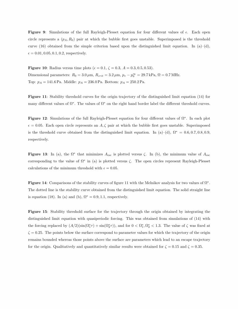
Figure 9: Simulations of the full Rayleigh-Plesset equation for four different values of ǫ. Each open
circle represents a (pA, R0) pair at which the bubble first goes unstable. Superimposed is the threshold
curve (16) obtained from the simple criterion based upon the distinguished limit equation. In (a)–(d),
ǫ = 0.01, 0.05, 0.1, 0.2, respectively.
Figure 10: Radius versus time plots (ǫ = 0.1, ζ = 0.3, A = 0.3, 0.5, 0.53).
Dimensional parameters: R0 = 3.0 µm, Rcrit = 3.2 µm, pv − p∞0
= 29.7 kPa, Ω = 0.7 MHz.
Top: pA = 141.6 Pa. Middle: pA = 236.0 Pa. Bottom: pA = 250.2 Pa.
Figure 11: Stability threshold curves for the origin trajectory of the distinguished limit equation (14) for
many different values of Ω∗. The values of Ω∗ on the right hand border label the different threshold curves.
Figure 12: Simulations of the full Rayleigh-Plesset equation for four different values of Ω∗. In each plot
ǫ = 0.05. Each open circle represents an A, ζ pair at which the bubble first goes unstable. Superimposed
is the threshold curve obtained from the distinguished limit equation. In (a)–(d), Ω∗ = 0.6, 0.7, 0.8, 0.9,
respectively.
Figure 13: In (a), the Ω∗ that minimizes Aesc is plotted versus ζ. In (b), the minimum value of Aesc
corresponding to the value of Ω∗ in (a) is plotted versus ζ. The open circles represent Rayleigh-Plesset
calculations of the minimum threshold with ǫ = 0.05.
Figure 14: Comparisons of the stability curves of figure 11 with the Melnikov analysis for two values of Ω∗.
The dotted line is the stability curve obtained from the distinguished limit equation. The solid straight line
is equation (18). In (a) and (b), Ω∗ = 0.9, 1.1, respectively.
Figure 15: Stability threshold surface for the trajectory through the origin obtained by integrating the
distinguished limit equation with quasiperiodic forcing. This was obtained from simulations of (14) with
the forcing replaced by (A/2)(sin(Ω∗
1τ) + sin(Ω∗
2τ)), and for 0 < Ω∗
1, Ω∗
2 < 1.3. The value of ζ was fixed at
ζ = 0.25. The points below the surface correspond to parameter values for which the trajectory of the origin
remains bounded whereas those points above the surface are parameters which lead to an escape trajectory
for the origin. Qualitatively and quantitatively similar results were obtained for ζ = 0.15 and ζ = 0.35.

PF#1091, Harkin, Nadim and Kaper – Figure 1
R
pL
pv
Rcrit
pLcrit

PF#1091, Harkin, Nadim and Kaper – Figure 2
−1 −0.5 0 0.5 1 1.5 2 2.5−1.5
−1
−0.5
0
0.5
1
1.5
(a)
−0.5 0 0.5 1 1.5
−1.2
−1
−0.8
−0.6
−0.4
−0.2
0
0.2
0.4
0.6
0.8
(b)

PF#1091, Harkin, Nadim and Kaper – Figure 3

PF#1091, Harkin, Nadim and Kaper – Figure 4
0 0.05 0.1 0.15 0.2 0.25 0.3 0.35 0.40
0.1
0.2
0.3
0.4
0.5
0.6
ζ
A
unstable
stable

PF#1091, Harkin, Nadim and Kaper – Figure 5
−0.5 0 0.5 1
−0.5
0
0.5
A=0.52
−0.5 0 0.5 1
−0.5
0
0.5
A=0.528
−0.5 0 0.5 1
−0.5
0
0.5
A=0.529
−0.5 0 0.5 1
−0.5
0
0.5
A=0.5
PF#1091, Harkin, Nadim and Kaper – Figure 6

PF#1091, Harkin, Nadim and Kaper – Figure 7

PF#1091, Harkin, Nadim and Kaper – Figure 8
0 0.05 0.1 0.15 0.2 0.25 0.3 0.35 0.40
0.1
0.2
0.3
0.4
0.5
0.6
ζ
A
unstable
stable
(a)
0 0.05 0.1 0.15 0.2 0.25 0.3 0.35 0.40
0.1
0.2
0.3
0.4
0.5
0.6
ζ
A
unstable
stable
(b)
0 0.05 0.1 0.15 0.2 0.25 0.3 0.35 0.40
0.1
0.2
0.3
0.4
0.5
0.6
ζ
A
unstable
stable
(c)
0 0.05 0.1 0.15 0.2 0.25 0.3 0.35 0.40
0.1
0.2
0.3
0.4
0.5
0.6
0.7
ζ
A
unstable
stable
(d)

PF#1091, Harkin, Nadim and Kaper – Figure 9
101
102
103
104
0
0.05
0.1
0.15
0.2
0.25
0.3
0.35
0.4
(micrometers)
(Pa
sca
ls)
unstable
stable
(a)
100
101
102
103
0
10
20
30
40
50
(micrometers)
(Pa
sca
ls)
unstable
stable
(b)
100
101
102
103
0
50
100
150
200
250
300
350
400
(micrometers)
(Pa
sca
ls)
unstable
stable
(c)
100
101
102
103
0
500
1000
1500
2000
2500
3000
3500
4000
(micrometers)
(Pa
sca
ls)
unstable
stable
(d)

PF#1091, Harkin, Nadim and Kaper – Figure 10
0 10 20 30 40 50 60 70 80 90 1000
50
100
150
0 10 20 30 40 50 60 70 80 90 1000.95
1
1.05
0 10 20 30 40 50 60 70 80 90 100
0.95
1
1.05
1.1

PF#1091, Harkin, Nadim and Kaper – Figure 11
0 0.05 0.1 0.15 0.2 0.25 0.3 0.35 0.40
0.1
0.2
0.3
0.4
0.5
0.6
0.7
0.8
ζ
A
Ω *
1.1
1.0
0.9
0.8
0.7
0.6
0.5
0.3
0.1
unstable
stable

PF#1091, Harkin, Nadim and Kaper – Figure 12
0 0.05 0.1 0.15 0.2 0.25 0.3 0.35 0.40
0.1
0.2
0.3
0.4
0.5
0.6
ζ
A
unstable
stable
(a)
0 0.05 0.1 0.15 0.2 0.25 0.3 0.35 0.40
0.1
0.2
0.3
0.4
0.5
0.6
ζ
A
unstable
stable
(b)
0 0.05 0.1 0.15 0.2 0.25 0.3 0.35 0.40
0.1
0.2
0.3
0.4
0.5
0.6
ζ
A
unstable
stable
(c)
0 0.05 0.1 0.15 0.2 0.25 0.3 0.35 0.40
0.1
0.2
0.3
0.4
0.5
0.6
ζ
A
unstable
stable
(d)

PF#1091, Harkin, Nadim and Kaper – Figure 13
0 0.05 0.1 0.15 0.2 0.25 0.3 0.35 0.40
0.1
0.2
0.3
0.4
0.5
0.6
0.7
0.8
0.9
1
ζ
Ω*
(a)
0 0.05 0.1 0.15 0.2 0.25 0.3 0.35 0.40
0.05
0.1
0.15
0.2
0.25
0.3
ζ
A
unstable
stable
(b)
PF#1091, Harkin, Nadim and Kaper – Figure 14
0 0.05 0.1 0.15 0.20
0.1
0.2
0.3
ζ
A
(a)
0 0.05 0.1 0.15 0.20
0.1
0.2
0.3
0.4
ζ
A
(b)

PF#1091, Harkin, Nadim and Kaper – Figure 15


![Electrochemical investigations of stable cavitation from bubbles …deymier/deymier_group/refs/cavitation... · 2014. 10. 15. · Rayleigh streaming, and Microstreaming [7]. In acoustic](https://static.fdocuments.in/doc/165x107/60a7b9340fce1a14d75ca4a9/electrochemical-investigations-of-stable-cavitation-from-bubbles-deymierdeymiergrouprefscavitation.jpg)