OMS2/xxx IS Interbus-SCourier type is used for text which is visible on the screen/display and for...
39
OMS2/xxx IS Interbus-S Operating Manual Laser Measuring Device Please keep for future use ! Edition date/Rev. date: 13.12.2002 Document/rev. no.: LZ - ELE - BA - GB - 0005 - 02 Software version: - Filename: LZ-ELE-BA-GB-0005.DOC Author: MÜJ Leuze electronic GmbH + Co. Postfach 11 11, D-73277 Owen/Teck In der Braike1, D-73277 Owen/Teck Telephone ++49 (0) 70 21 / 57 30 Telefax ++49 (0) 70 21 / 57 31 99
Transcript of OMS2/xxx IS Interbus-SCourier type is used for text which is visible on the screen/display and for...

OMS2/xxx IS Interbus-S
Operating Manual Laser Measuring Device
Please keep for future use ! Edition date/Rev. date: 13.12.2002 Document/rev. no.: LZ - ELE - BA - GB - 0005 - 02 Software version: - Filename: LZ-ELE-BA-GB-0005.DOC Author: MÜJ
Leuze electronic GmbH + Co. Postfach 11 11, D-73277 Owen/Teck In der Braike1, D-73277 Owen/Teck Telephone ++49 (0) 70 21 / 57 30 Telefax ++49 (0) 70 21 / 57 31 99

Operating Manual #Leuze electronic GmbH + Co.
Impressum Leuze electronic GmbH + Co. Postfach 11 11, D-73277 Owen/Teck In der Braike1, D-73277 Owen/Teck Tel.: (0049) 07021/5730 Fax: (0049) 07021/573199 Copyright 2002 Leuze electronic Right of modification
We reserve the right to make modifications to the information contained in this document at any time in the interests of improving our products.
Notation
Italics or bold print is used for titles of documents or for emphasis. Courier type is used for text which is visible on the screen/display and for software menu selections. ″ < > ″ is used to refer to the keys of your computer keyboard (e.g. <RETURN>).
#Leuze electronic GmbH + Co., Postfach 11 11, D-73277 Owen/Teck, In der Braike1, D-73277 Owen/Teck, Tel. ++49 (0)7021/5730, Fax ++49 (0)7021/573199 Date: 13.12.2002 LZ - ELE - BA - GB - 0005 - 02 Page 2 of 36

Operating Manual #Leuze electronic GmbH + Co.
Revision index
i Note The current revision number and date appears on the front cover of this document. Since the footer of each individual page contains its own revision number and date, the revision status may vary within the same document. The drawings included in the appendix have their own revision index. Document issued: 25.10.2002
Revision Date
Correction of the wiring diagram and pin assignment concerning the bus reference potentials 06.12.2002
Completion of the malfunction code: • 1001 = Intensity warning
13.12.2002
#Leuze electronic GmbH + Co., Postfach 11 11, D-73277 Owen/Teck, In der Braike1, D-73277 Owen/Teck, Tel. ++49 (0)7021/5730, Fax ++49 (0)7021/573199 Date: 13.12.2002 LZ - ELE - BA - GB - 0005 - 02 Page 3 of 36

Operating Manual #Leuze electronic GmbH + Co.
Table of Contents 1 Safety..............................................................................................................................................6
1.1 General risk potential.......................................................................................................6 1.2 Safety information............................................................................................................6
1.2.1 Hints on installation..........................................................................................7 1.2.1.1 General interference suppression measures ..................................8
1.3 Intended purpose.............................................................................................................9 1.4 Authorised operators .......................................................................................................11 1.5 Safety measures at the installation site...........................................................................11
2 Transportation / Start-up ..............................................................................................................12 2.1 Transportation / storage ..................................................................................................12 2.2 Assembly instructions......................................................................................................13
2.2.1 Aligning of the reflector to the laser measuring device....................................13 2.2.2 Aligning of the laser light spot to the reflector .................................................13 2.2.3 Parallel operation of laser linear paths ............................................................14
2.3 Start-up ............................................................................................................................15 2.3.1 General ............................................................................................................15 2.3.2 Connecting the Cable Screening to the Bus-Cap............................................16 2.3.3 Wiring...............................................................................................................17 2.3.4 Device interface (INTERBUS-S)......................................................................20
2.3.4.1 Mapping of Laser Data in the Master (Controller) ...........................21 2.3.4.2 Control Word (OUT-data relative to the master)..............................22 2.3.4.3 Status Word (IN-data relative to the master) ...................................24
3 Parameter programming...............................................................................................................26 3.1 Parameter description .....................................................................................................29
3.1.1 Resolution........................................................................................................29 3.1.2 Switching-off laser diode..................................................................................29 3.1.3 Switching-on laser diode .................................................................................29 3.1.4 Preset preselection ..........................................................................................30 3.1.5 Switch off laser diode automatic if Interbus-S is inactive ................................30 3.1.6 Counting direction............................................................................................30 3.1.7 Error value .......................................................................................................30 3.1.8 Function external input ....................................................................................31 3.1.9 Clear Preset.....................................................................................................31 3.1.10 Save parameters ...........................................................................................31
4 Disturbances..................................................................................................................................32 4.1 Causes of Faults and Remedies .....................................................................................32
5 Maintenance...................................................................................................................................33 5.1 General Maintenance Information ...................................................................................33 5.2 Repair, Maintenance .......................................................................................................33
6 Appendix ........................................................................................................................................34 6.1 Specifications...................................................................................................................34
6.1.1 Electrical ratings ..............................................................................................34 6.1.2 Environmental conditions.................................................................................35
6.2 Accessories .....................................................................................................................36 #Leuze electronic GmbH + Co., Postfach 11 11, D-73277 Owen/Teck, In der Braike1, D-73277 Owen/Teck, Tel. ++49 (0)7021/5730, Fax ++49 (0)7021/573199 Date: 13.12.2002 LZ - ELE - BA - GB - 0005 - 02 Page 4 of 36

Operating Manual #Leuze electronic GmbH + Co.
Pin assignment .......................................................................................... LZ-ELE-TI-GB-0005 Drawings Dimensioned drawing .............................................................................04-K2200-001
#Leuze electronic GmbH + Co., Postfach 11 11, D-73277 Owen/Teck, In der Braike1, D-73277 Owen/Teck, Tel. ++49 (0)7021/5730, Fax ++49 (0)7021/573199 Date: 13.12.2002 LZ - ELE - BA - GB - 0005 - 02 Page 5 of 36

Operating Manual #Leuze electronic GmbH + Co.
1 Safety
1.1 General risk potential The Laser Measuring Device OMS2 Interbus-S cannot be operated independently, but is installed as part of an overall system usually consisting of several interacting components. For this reason, the laser measuring device is not equipped directly with a protective device. Warning However, different error reports can be read out via a status word. The error reports are classified over a malfunction code. (see page 27). It is therefore essential to integrate the malfunction code into your own safety system via the evaluation software (e.g. a PLC). The corresponding measures must be taken in order to avoid person and property damages. All persons responsible for the assembly, start-up and operation of the device must
• be suitably qualified • adhere strictly to this operating manual. Your safety and the safety of your equipment depends on this!
1.2 Safety information This operating manual contains information which must be observed in the interests of your own personal safety and that of your equipment. The safety hints are emphasised by a warning triangle and classified according to the degree of danger as follows: Warning means that failure to take the relevant safety precautions can lead to death, serious injury or major damage to property. Caution means that failure to take the relevant safety precautions can lead to minor injuries or damage to property.
i Note refers to important information and features of the product, plus tips on its application.
#Leuze electronic GmbH + Co., Postfach 11 11, D-73277 Owen/Teck, In der Braike1, D-73277 Owen/Teck, Tel. ++49 (0)7021/5730, Fax ++49 (0)7021/573199 Date: 13.12.2002 LZ - ELE - BA - GB - 0005 - 02 Page 6 of 36

Operating Manual #Leuze electronic GmbH + Co.
1.2.1 Hints on installation Since the Laser Measuring Device is normally used as part of a larger system, these hints are merely intended as a guide for integrating the device safely into its environment. Warning • The safety and accident prevention regulations applicable to the specific
application must be observed. • In the case of permanently installed plants or systems without an all-pole mains
switch and/or fuses, one of these devices must be installed accordingly and the equipment connected to a PE conductor.
• In the case of devices which run on mains voltage, make sure the set nominal
voltage range coincides with the local mains voltage before start-up. • In the case of 24 V supplies, make sure the extra-low voltage is reliably
disconnected. Only use power supply units manufactured to the standards IEC 364 - 4 - 41 / HD 384.04.41 (VDE 0100 Part 410).
• Fluctuations or deviations of the mains voltage from the nominal value must not
exceed the tolerance limits stated in the specifications, otherwise operational failures and dangerous states in the electrical assemblies cannot be ruled out.
• Precautionary measures must be taken to allow an interrupted program to be
properly resumed following a voltage drop or failure. Dangerous operating conditions must not be permitted to arise even for short periods. If necessary, an "EMERGENCY STOP" must be forced.
• EMERGENCY STOP devices according to EN 60204/IEC 204 (VDE 0113) must
remain operational in all operating modes of the programmable controller. The release of the EMERGENCY STOP devices must not trigger an uncontrolled or undefined reactivation of the equipment.
• Connecting and signal wires must be installed in such a way as to prevent the
automation functions from being hampered by inductive and capacitive interference.
• The units of the automation system and their operating elements must be installed
in such a way as to ensure adequate protection against accidental actuation. • In order to prevent a wire or strand breakage on the signal side from causing
undefined states in the programmable controller, suitable hardware and software safety precautions must be taken with regard to the I/O interface.
#Leuze electronic GmbH + Co., Postfach 11 11, D-73277 Owen/Teck, In der Braike1, D-73277 Owen/Teck, Tel. ++49 (0)7021/5730, Fax ++49 (0)7021/573199 Date: 13.12.2002 LZ - ELE - BA - GB - 0005 - 02 Page 7 of 36

Operating Manual #Leuze electronic GmbH + Co.
1.2.1.1 General interference suppression measures • Lay the (shielded) connecting cable to the device at a sufficient distance or in a
separate room from any power cables which are subject to interference. • To ensure reliable data transmission, use fully shielded cables and make sure they
are well earthed. For differential data transfer (RS422, RS485 etc.), twisted-pair wires must be used in addition.
• Use a minimum cable cross-section of 0.22 mm2 for data transfer purposes. • Use a minimum earthing cable cross-section of 10 mm2 in order to avoid
equipotential currents across the shield. Make sure the resistance of the earthing cable is much lower than that of the shield.
• Ensure continuous wiring of the shield and a large contact area on special shield
connecting terminals. • Avoid crossing cables where possible. If unavoidable, only cross them at right-
angles.
#Leuze electronic GmbH + Co., Postfach 11 11, D-73277 Owen/Teck, In der Braike1, D-73277 Owen/Teck, Tel. ++49 (0)7021/5730, Fax ++49 (0)7021/573199 Date: 13.12.2002 LZ - ELE - BA - GB - 0005 - 02 Page 8 of 36

Operating Manual #Leuze electronic GmbH + Co.
1.3 Intended purpose The measuring system is used for recording linear movements and processing the measured data for a downstream control system with a INTERBUS-S interface according to DIN 19258. The classification of the measuring system is defined according to the profile K3. At this the encoder data uses 2-word addresses for IN-data and 2-word addresses for OUT-data in the Master. Warning
Switch off the voltage supply before carrying out wiring work or opening and closing electrical connections! Short-circuits, voltage peaks, etc. can cause operating failures and uncontrolled operating states, as well as serious personal injuries and damage to property. Check all electrical connections before switching on the system! Incorrectly wired connections can cause operating failures, while wrong connections can lead to serious personal injuries and damage to property. Mechanical or electrical modifications to the measuring systems are prohibited for safety reasons! In particular the following uses are forbidden
- operation in areas where interruption of the laser beam, e.g. by covering the laser lens opening, can lead to equipment damage or injury to personnel
- in environments, in which strong rain, snow, fog, steams or direct insolations etc. can influence the laser beam intensity negatively
- operation in rooms with explosive atmospheres - operation for medical purposes
With use-purposes over 115m measuring length, a special reflector must to be used! (see chapter "Accessories", page 36)
#Leuze electronic GmbH + Co., Postfach 11 11, D-73277 Owen/Teck, In der Braike1, D-73277 Owen/Teck, Tel. ++49 (0)7021/5730, Fax ++49 (0)7021/573199 Date: 13.12.2002 LZ - ELE - BA - GB - 0005 - 02 Page 9 of 36

Operating Manual #Leuze electronic GmbH + Co.
Caution
Laser beam Do not look into the beam Laser class : 2 Acc. to EN 60 825-1 : 1994 Max. laser power Pmax. : ≤ 1 mW Wavelength λ : 670 nm • In the case of Class 2 laser devices, the eye is protected against brief, accidental
glances at the beam by the blinking reflex. For this reason, devices of this class can be used without additional protective measures provided the operator is not required to look into the laser beam deliberately for longer periods, i.e. 0.25 s, or to look repeatedly into the laser beam itself or the directly reflected beam.
• The device must be installed in such a way that the exposure of persons to the
laser beam can only happen accidentally. • The laser beam may only extend as far as is necessary for the range
measurement. The beam must be limited at the end of the useful range by a diffusely reflecting target area in such a way as to minimise the danger from direct or diffuse reflection. For this purpose, you should use the Leuze electronic reflecting foil supplied with the device.
• The area outside the operating range where the unshielded laser beam falls should
be limited as far as possible and should remain out of bounds, particularly in the area above and below eye level.
i Note The start-up, operating and programming instructions contained in this manual are mandatory.
#Leuze electronic GmbH + Co., Postfach 11 11, D-73277 Owen/Teck, In der Braike1, D-73277 Owen/Teck, Tel. ++49 (0)7021/5730, Fax ++49 (0)7021/573199 Date: 13.12.2002 LZ - ELE - BA - GB - 0005 - 02 Page 10 of 36

Operating Manual #Leuze electronic GmbH + Co.
1.4 Authorised operators The start-up and operation of this device may only be performed by qualified personnel. For the purposes of this manual, the term "qualified personnel" refers to persons who are authorised to operate, earth and label equipment, systems and power circuits according to recognised safety standards.
1.5 Safety measures at the installation site Warning Do not perform any welding work once the device is connected and switched on! Variations in potential can destroy the device or restrict its operation. Do not touch plug contacts with your hands! Static charges may destroy electronic components of the device. Do not connect unused inputs (see pin assignment)! Observe the voltage supply range: Standard device: 18-27 V DC (+/- 5 %) Device with heating: 24 V DC Clean lens opening of the laser and the reflecting foil regularly! (see chapter "Maintenance", page 33)
i Note Make sure that the environment of the installation site is protected against corrosive media (acids, etc.)
#Leuze electronic GmbH + Co., Postfach 11 11, D-73277 Owen/Teck, In der Braike1, D-73277 Owen/Teck, Tel. ++49 (0)7021/5730, Fax ++49 (0)7021/573199 Date: 13.12.2002 LZ - ELE - BA - GB - 0005 - 02 Page 11 of 36

Operating Manual #Leuze electronic GmbH + Co.
2 Transportation / Start-up
2.1 Transportation / storage Transport instructions Do not drop the device or expose it to shocks or vibrations! Device contains an optical system with glass elements. Only use the original packaging! The wrong packaging material can cause damage to the device during transportation. Storage Storage temperature : -20 to +75°C Store in dry conditions.
#Leuze electronic GmbH + Co., Postfach 11 11, D-73277 Owen/Teck, In der Braike1, D-73277 Owen/Teck, Tel. ++49 (0)7021/5730, Fax ++49 (0)7021/573199 Date: 13.12.2002 LZ - ELE - BA - GB - 0005 - 02 Page 12 of 36

Operating Manual #Leuze electronic GmbH + Co.
2.2 Assembly instructions
2.2.1 Aligning of the reflector to the laser measuring device The coating of the reflector surface indicates a honeycombed structure. To guarantee an interference-free operation of the laser linear path, the alignment of the structure and the angle of inclination of the foil to the laser is from special importance:
A
A
A
±3 - 4°
±3 - 4°
Foil must be inclined either in the Y-axis or in the Z-axis 3-4°!
2.2.2 Aligning of the laser light spot to the reflector The measuring device or reflector is attached to the moving object and the reflector/sensor to the fixed remote station in such a way that the reflector always remains within the visual field of the sensor. This can be done using the light spot of the laser diode, which is still clearly visible on the reflecting foil even at long distance. When aligning the laser measuring device, the user may need to take measures to ensure that it can be mechanically adjusted. The size of the reflecting foil must be such that the light spot cannot be displaced from the reflector by vibrations. The device comes with a reflecting foil measuring 20 x 20 [cm], but other sizes can be ordered on request. Once the Laser Measuring Device is optimally aligned with the reflecting foil, the device control command "Enable operation" must be sent for resetting the malfunction code 1100 (Intensity error).
i Note Reflecting foils by other manufacturers should be used only after consultation with Leuze electronic, as all the information in the "Specifications" chapter refers to the foil already supplied with the device.
#Leuze electronic GmbH + Co., Postfach 11 11, D-73277 Owen/Teck, In der Braike1, D-73277 Owen/Teck, Tel. ++49 (0)7021/5730, Fax ++49 (0)7021/573199 Date: 13.12.2002 LZ - ELE - BA - GB - 0005 - 02 Page 13 of 36

Operating Manual #Leuze electronic GmbH + Co.
2.2.3 Parallel operation of laser linear paths It has to be taken care in the parallel operation of laser linear paths that a minimum distance of 1 m is kept. The reflector foil inclination must be made in such a way that the foil surface points in each case to the other laser linear path away. Horizontal arrangement
3-4°
min
. 1m
3-4°
Vertical arrangement
3-4°
3-4°min
. 1m
#Leuze electronic GmbH + Co., Postfach 11 11, D-73277 Owen/Teck, In der Braike1, D-73277 Owen/Teck, Tel. ++49 (0)7021/5730, Fax ++49 (0)7021/573199 Date: 13.12.2002 LZ - ELE - BA - GB - 0005 - 02 Page 14 of 36

Operating Manual #Leuze electronic GmbH + Co.
2.3 Start-up
2.3.1 General The OMS2 series Laser Measuring Devices are optical sensors for contactless measurement of the distance between the sensor and a reflector. For this purpose, the measuring device or reflector attached to the moving object and the reflector/sensor to the fixed remote station in such a way that the reflector always remains within the visual field of the sensor. The laser diode inside the device emits a beam which bounces back off the reflector and is re-received by a detector also housed inside the measuring device. The phase angle of the received signal in relation to the transmitted signal is the measure of distance. The absolute distance value thus obtained is then transferred to the control system via the interface. The Laser Measuring Devices are configured by a automation device (PLC, process control computer) directly via the Interbus-S. Principle:
Reflecting foil
ϕ
transmitter signal
Receiver signal
ϕ = Phase displacement d = Distance d = f (ϕ)
Display range max. 170m (Special Device)
Measuring rangeMeasuring start Measuring end
125m0,2m
#Leuze electronic GmbH + Co., Postfach 11 11, D-73277 Owen/Teck, In der Braike1, D-73277 Owen/Teck, Tel. ++49 (0)7021/5730, Fax ++49 (0)7021/573199 Date: 13.12.2002 LZ - ELE - BA - GB - 0005 - 02 Page 15 of 36

Operating Manual #Leuze electronic GmbH + Co.
2.3.2 Connecting the Cable Screening to the Bus-Cap To prevent disturbance signals entering the laser housing, we used cable screw glands with which it is possible to connect the screen on the inside. For this reason, no connection point for the screen is provided inside the cup-cap. Procedure: 1. Screw the cable screw gland into the housing.
2. Dismount the compression nut (1) and the terminal holder (2).
3. Push the compression nut (1) and the terminal holder (2) over the cable.
4. Strip the cable; push back the braiding around the terminal holder (2) such that the
braiding goes over the inner O-ring (3) and does not lie over the cylindrical section
or the torsional bars.
5. Insert the terminal holder (2) into the intermediate gland (4) such that the torsional
bars fit into the intended lengthwise grooves in the intermediate gland (4).
6. Screw the compression nut (1) to the intermediate gland (4).
Part 1Compression nut
Part 2Terminal holder
Part 3Inner O-ring
Part 4Intermediate gland
#Leuze electronic GmbH + Co., Postfach 11 11, D-73277 Owen/Teck, In der Braike1, D-73277 Owen/Teck, Tel. ++49 (0)7021/5730, Fax ++49 (0)7021/573199 Date: 13.12.2002 LZ - ELE - BA - GB - 0005 - 02 Page 16 of 36

Operating Manual #Leuze electronic GmbH + Co.
2.3.3 Wiring 1. Configuration of the OMS2 via the Interbus-S
The OMS2 with Interbus-S interface offers the possibility to configure the most important device parameter via the Interbus-S.
2. Configuration of the OMS2 via the PC-adapter and PC-program "OMSConfiguration Tool" In addition, via an optional available PC adapter (MA OMS1 PCA), the OMS2 can be programmed with additional functions. For this, the 15 pole connector of the PC adapter must be connected with the switch cabinet module (MA OMS1 PCAS). Pin 1 (RS 485-) and pin 2 (RS 485+) of the switch cabinet module must be connected with the OMS2 pin 9 (RS 485-) and pin 10 (RS 485+) (see wiring on the following pages). Via the PC adapter all device parameters are programmable, the main parameters of the device also can be configured via the Interbus-S. The parameters which are configured via the Interbus-S always have priority. If the control executes a "Download" of the slave parameters, these always have priority. Parameters, which possibly have been configured double via the PC adapter, will be retyped with the download of the control parameters.
Connection panel
X1
1 20
RD URCBA
#Leuze electronic GmbH + Co., Postfach 11 11, D-73277 Owen/Teck, In der Braike1, D-73277 Owen/Teck, Tel. ++49 (0)7021/5730, Fax ++49 (0)7021/573199 Date: 13.12.2002 LZ - ELE - BA - GB - 0005 - 02 Page 17 of 36

Operating Manual #Leuze electronic GmbH + Co.
Connection diagram for Interbus-S connection
Jumper for the identification, that a further slave is following!
Last slave,since /RBST isn’t wired!
181715201916
78
DO1
/DO1
GNDI
LASER OMS2 Interbus-S
/DI1
Shield
0V
V DC
1211
1413X1
54
X1
DO2
/DO2
DI2
/DI2
/RBST
GND
From the previousslave
181715201916
78
DO1
/DO1
GNDI
LASER OMS2 Interbus-S
/DI1
Shield
0V
V DC
1211
1413
54
X1 X1
DO2
/DO2
DI2
/DI2
/RBST
GND
Power Supply Power Supply
Connect on cablegland!
Laser 1 Laser 2
CaseCase
Connect on cablegland!
Connect oncable gland!
Optical displaysLED RD (red): Following IBS-Interface is disconnected, or bus communication disturbed!LED RC (green): Remote-ControlLED U (green): SUPI Supply VoltageLED BA (green): Interbus-S active
GND 6 GND 6
#Leuze electronic GmbH + Co., Postfach 11 11, D-73277 Owen/Teck, In der Braike1, D-73277 Owen/Teck, Tel. ++49 (0)7021/5730, Fax ++49 (0)7021/573199 Date: 13.12.2002 LZ - ELE - BA - GB - 0005 - 02 Page 18 of 36

Operating Manual #Leuze electronic GmbH + Co.
Connection diagram for Interbus-S connection with parametrizing possibility via PC adapter MA OMS1 PCA / PC
18171520191610978
DO1
/DO1
GNDI
LASER OMS2 Interbus-S
/DI1
Shield
RS485+
RS485-
0V
V DC
1211
1413X1
54
X1
DO2
/DO2
DI2
/DI2
/RBST
GND
from the previousslave
Jumper for the identification, that a further slave is following!
DO1
/DO1
GNDI
LASER OMS2 Interbus-S
/DI1
Shield
RS485+
RS485-
0V
V DC
X1 X1
DO2
/DO2
DI2
/DI2
/RBST
GNDLast slave,since /RBST isn’t wired!
Connect on cable gland!
Laser 1 Laser 2
CaseCase
1 2 3 4 7 8 1011 1213141516
PCConfigurationSoftware“OMSConfi-guration”
COM
5 6 9
+ -Power supply
MA OMS1 PCA
RS 232
Ribbon Cable
15-pol. SUB-D
1 2 3 4 7 8 1011 12131415165 6 9
1 2 3 4 7 8 1011 12131415165 6 9
1 2 3 4 7 8 1011 12131415165 6 9
+ -Power suPply
For programming connectPC adapter MA OMS1 PCA !
Optical displays
LED RD (red): Following IBS-Interface is disconnected, or bus communication disturbed!LED RC (green): Remote-ControlLED U (green): SUPI Supply VoltageLED BA (green): Interbus-S active
Connect on cable gland!
Connect on cablegland!
18171520191610978
1211
1413
54
MA OMS1 PCAS
MA OMS1 PCAS
GND 6 GND 6
#Leuze electronic GmbH + Co., Postfach 11 11, D-73277 Owen/Teck, In der Braike1, D-73277 Owen/Teck, Tel. ++49 (0)7021/5730, Fax ++49 (0)7021/573199 Date: 13.12.2002 LZ - ELE - BA - GB - 0005 - 02 Page 19 of 36
Operating Manual #Leuze electronic GmbH + Co.
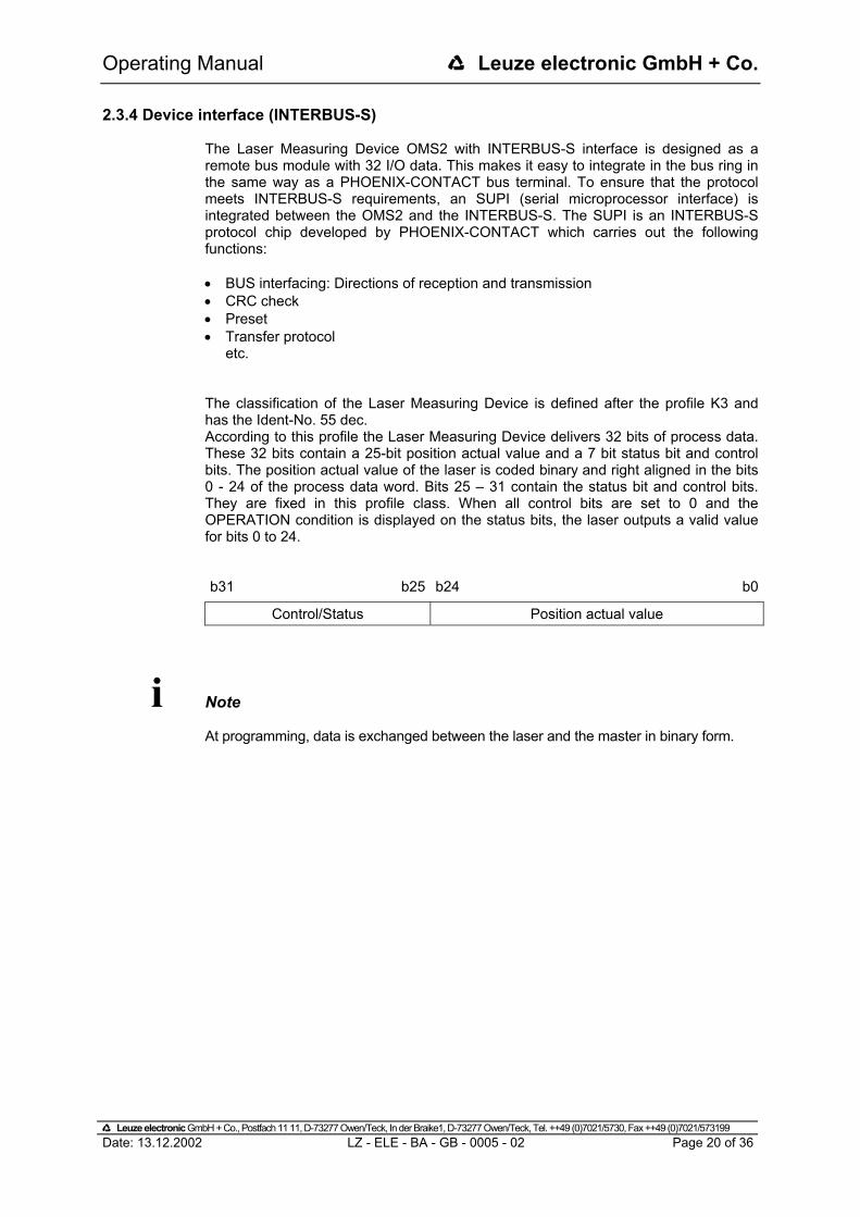
2.3.4 Device interface (INTERBUS-S) The Laser Measuring Device OMS2 with INTERBUS-S interface is designed as a remote bus module with 32 I/O data. This makes it easy to integrate in the bus ring in the same way as a PHOENIX-CONTACT bus terminal. To ensure that the protocol meets INTERBUS-S requirements, an SUPI (serial microprocessor interface) is integrated between the OMS2 and the INTERBUS-S. The SUPI is an INTERBUS-S protocol chip developed by PHOENIX-CONTACT which carries out the following functions: • BUS interfacing: Directions of reception and transmission • CRC check • Preset • Transfer protocol
etc. The classification of the Laser Measuring Device is defined after the profile K3 and has the Ident-No. 55 dec. According to this profile the Laser Measuring Device delivers 32 bits of process data. These 32 bits contain a 25-bit position actual value and a 7 bit status bit and control bits. The position actual value of the laser is coded binary and right aligned in the bits 0 - 24 of the process data word. Bits 25 – 31 contain the status bit and control bits. They are fixed in this profile class. When all control bits are set to 0 and the OPERATION condition is displayed on the status bits, the laser outputs a valid value for bits 0 to 24. b31 b25 b24 b0
Control/Status Position actual value
i Note At programming, data is exchanged between the laser and the master in binary form.
#Leuze electronic GmbH + Co., Postfach 11 11, D-73277 Owen/Teck, In der Braike1, D-73277 Owen/Teck, Tel. ++49 (0)7021/5730, Fax ++49 (0)7021/573199 Date: 13.12.2002 LZ - ELE - BA - GB - 0005 - 02 Page 20 of 36

Operating Manual #Leuze electronic GmbH + Co.
2.3.4.1 Mapping of Laser Data in the Master (Controller)
In the master, the laser data occupies two-word addresses for IN-data and two-word addresses for OUT-data. The position of the data in the controller depends on the physical or logical position of the encoder within the ring. For detailed information, refer to the manual of the master (controller) used. The laser should be considered to be a PHOENIX I/O bus terminal and the system processes it as such.
Double Input Word ID x
Data byte 3 Data byte 2 Data byte 1 Data byte 0
B15 B14 B13 B12 B11 B10 B9 B8 B7 B6 B5 B4 B3 B2 B1 B0
231 230 229 228 227 226 225 224 223 222 221 220 219 218 217 216 215 214 213 212 211 210 29 28 27 26 25 24 23 22 21 20 Input byte x+0 Input byte x+1 Input byte x+2 Input byte x+3
Double Output Word OD x
Data byte 3 Data byte 2 Data byte 1 Data byte 0
B15 B14 B13 B12 B11 B10 B9 B8 B7 B6 B5 B4 B3 B2 B1 B0
231 230 229 228 227 226 225 224 223 222 221 220 219 218 217 216 215 214 213 212 211 210 29 28 27 26 25 24 23 22 21 20 Output byte x+0 Output byte x+1 Output byte x+2 Output byte x+3
#Leuze electronic GmbH + Co., Postfach 11 11, D-73277 Owen/Teck, In der Braike1, D-73277 Owen/Teck, Tel. ++49 (0)7021/5730, Fax ++49 (0)7021/573199 Date: 13.12.2002 LZ - ELE - BA - GB - 0005 - 02 Page 21 of 36

Operating Manual #Leuze electronic GmbH + Co.
2.3.4.2 Control Word (OUT-data relative to the master)
Via the control word functions activated and the operational states of the laser are defined. Control Word, relative word address "0"
Bit Name Mandatory Bit-No. in PD-Channel
0 Reserved 16 1 Reserved 17 2 Reserved 18 3 Reserved 19 4 Reserved 20 5 Reserved 21 6 Reserved 22 7 Reserved 23 8 Reserved 24 9 Parameter no. X 25 10 Parameter no. X 26 11 Parameter no. X 27 12 Parameter no. X 28 13 Manufacturer-specific 29 14 * Set zero shift X 30 15 Enable operation X 31
* see page 23, "Set zero shift" Device Control Commands The device control commands are triggered by the following bit combinations in the control word:
Control Word (bit) Enable
operation Set zero
shift Manufac-
turer- specific
Parameter-No. DEVICE CONTROL COMMAND 15 14 13 12 11 10 9
ENABLE OPERATION 0>1 0 X 0 PARAMETERIZATION 0 0 X 1 . . . 15
#Leuze electronic GmbH + Co., Postfach 11 11, D-73277 Owen/Teck, In der Braike1, D-73277 Owen/Teck, Tel. ++49 (0)7021/5730, Fax ++49 (0)7021/573199 Date: 13.12.2002 LZ - ELE - BA - GB - 0005 - 02 Page 22 of 36

Operating Manual #Leuze electronic GmbH + Co.
Parameter-No. The bits 9 to 12 (D25 - D28) indicate the number of the parameter at the laser. The parameter data will transfer via the bits 0 to 24 of the process out data channel. The activation of parameter transfer is receipted within a second in the status word. (see also "Parameter programming", page 26) Set zero shift If in parameter-no. 1101 is programmed the value "0 = not clear", an edge change of "0" to "1" of the bit-no. 30 in the process out data channel is setting the laser to the preselected value in parameter-no. 0100 (see also "Parameter overview", page 26). Manufacturer-Specific Bits 0 - 8 are reserved. Bit 13 is manufacturer-specific.
#Leuze electronic GmbH + Co., Postfach 11 11, D-73277 Owen/Teck, In der Braike1, D-73277 Owen/Teck, Tel. ++49 (0)7021/5730, Fax ++49 (0)7021/573199 Date: 13.12.2002 LZ - ELE - BA - GB - 0005 - 02 Page 23 of 36

Operating Manual #Leuze electronic GmbH + Co.
2.3.4.3 Status Word (IN-data relative to the master) Information concerning the state of the laser and messages are shown in the status word. Status Word, relative word address "0"
Bit Name Mandatory Bit-No. in PD-Channel
0 Reserved 16 1 Reserved 17 2 Reserved 18 3 Reserved 19 4 Reserved 20 5 Reserved 21 6 Reserved 22 7 Reserved 23 8 Reserved 24 9 Parameter no. or malfunction code X 25 10 Parameter no. or malfunction code X 26 11 Parameter no. or malfunction code X 27 12 Parameter no. or malfunction code X 28 13 Manufacturer-specific 29 14 Parameterization X 30 15 Invalid position actual value X 31
Device States The device states are shown in the status word by the following bit combinations:
Status Word (bit) Invalid
position actual value
Parameter-
ization
Manufac-turer
specific
Parameter-No. STATE 15 14 13 12 11 10 9
OPERATION 0 0 X 0 PARAMETERIZATION 1 1 X 1 . . . 15 MALFUNCTION 1 0 X 1 . . . 15
#Leuze electronic GmbH + Co., Postfach 11 11, D-73277 Owen/Teck, In der Braike1, D-73277 Owen/Teck, Tel. ++49 (0)7021/5730, Fax ++49 (0)7021/573199 Date: 13.12.2002 LZ - ELE - BA - GB - 0005 - 02 Page 24 of 36

Operating Manual #Leuze electronic GmbH + Co.
Parameter No. or Malfunction Code The number of the parameter that was transmitted to the laser is acknowledged via bits 9 to 12, or a malfunction code is transmitted (in "malfunction" state). (see page 27) Manufacturer-Specific Bits 0 - 8 are reserved. Bit 13 is manufacturer-specific.
#Leuze electronic GmbH + Co., Postfach 11 11, D-73277 Owen/Teck, In der Braike1, D-73277 Owen/Teck, Tel. ++49 (0)7021/5730, Fax ++49 (0)7021/573199 Date: 13.12.2002 LZ - ELE - BA - GB - 0005 - 02 Page 25 of 36

Operating Manual #Leuze electronic GmbH + Co.
3 Parameter programming
The parameter data can be transferred via the bits 0 to 24 of the process out data channel of the master to the laser. To this the laser must be set to the parameterization state. This is achieved by outputting a parameter number unequal to zero on bits 9 to 12 of the control word (bits 25 to 28 of the process out data channel). Parameter overview
Parameter No. B12 B9 Function
0 0 0 0 Output in "operation" state
0 0 0 1
Resolution: 0 = 10 mm 1 = 1 mm 2 = 0,1 mm 3 = 0,01 mm 4 = 1 Inch 5 = 0,1 Inch
0 0 1 0 Switch off laser diode
0 0 1 1 Switch on laser diode
0 1 0 0 Preselection preset value
0 1 0 1 Automatic switching-off of the laser diode, if bus 15min. inactively:
0 = disabled 1 = active
0 1 1 0 Not defined !
0 1 1 1 Not defined !
1 0 0 0 Counting direction:
0 = From the laser away, values increasing 1 = To the Laser, values increasing
1 0 0 1 Not defined !
1 0 1 0 Error value at beam interruption:
0 = NULL 1 = 0xFF 2 = Last valid position value
1 0 1 1 Not defined !
1 1 0 0 Function external input:
0 = disabled 1 = Preset 2 = Switch off laser diode
1 1 0 1 Clear preset (Zero mark is deleted): 0 = No clearing 1 = Clearing
1 1 1 0 Not defined !
1 1 1 1 Save parameters, D0 – D24 = "0" The laser switches over to the "parameterization" state and indicates the successful transmission of the parameter with the return of the corresponding parameter number. The new parameter takes effect after the user has set the laser to the ’operation’ state with the ’enable operation’ device control command. If it was not possible for the parameter to take effect, the laser switches over to the ’malfunction’ state –after the user has sent the ’enable operation’ device control command - and outputs a malfunction number on bits 9 to 12 of the status word (bit 25 to 28 of the process data channel).
#Leuze electronic GmbH + Co., Postfach 11 11, D-73277 Owen/Teck, In der Braike1, D-73277 Owen/Teck, Tel. ++49 (0)7021/5730, Fax ++49 (0)7021/573199 Date: 13.12.2002 LZ - ELE - BA - GB - 0005 - 02 Page 26 of 36

Operating Manual #Leuze electronic GmbH + Co.
Malfunction code
Malfunction-No. b12 b9 Meaning
0 0 0 0 No malfunction 0 0 0 1 Invalid parameters from the host 0 0 1 1 Hardware error 1 0 0 1 Intensity warning (intensity <12%) 1 0 1 0 Laser diode is switched off 1 1 0 0 Intensity error (e.g. beam interruption) 1 1 1 0 Device temperature (outside the range of 0-50 °C) 1 1 1 1 Manufacturer-specific malfunction code
EXAMPLE 1: Example of a Parameter Transmission
Host to Laser Laser to Host
Control Word Status Word
D31 D25-D28 D0-D24 D30-D31 D25-D28 D0-D24
Comment
1 0 0 X 0 0 0 Actual value Normal operation
2 0 P.No. Parameter 0 0 0 Actual value
Host transmits parameter to laser, laser does not yet react
3 0 P.No. Parameter 0 0 0 Actual value
Host continues to wait for acknowledgement from laser
4 0 P.No. Parameter 1 1 1) X Laser has accepted the parameter and begins processing
5 0 P.No. Parameter 1 1 1) X Parameter processing still running in laser
6 0 P.No. Parameter 1 1 P.No. ParameterProcessing of parameter is comple-ted. Laser remains in "parameteriza-tion" state
7 1 0 0 1 1 P.No. ParameterDevice control command "enable operation" from host to the laser. Laser does not yet react
8 1 0 0 0 0 0 Actual value Laser once more in "operation" state
9 0 0 0 0 0 0 Actual value
Normal operating mode once more reached by both devices
1): You must make sure that when a parameter is transmitted, the same parameter number as that which has already been acknowledged by the laser is not sent. The repeated transmission of the same parameter is not valid without first leaving the "parameterization" state. The parameter number must be consistent. To transmit several parameters, repeat steps 4 to 6. When transmitting a parameter, make sure that the parameter number is not output before the parameter. When invalid or inconsistent parameters are sent, the laser goes into the "malfunction" state when trying to enable operation.
#Leuze electronic GmbH + Co., Postfach 11 11, D-73277 Owen/Teck, In der Braike1, D-73277 Owen/Teck, Tel. ++49 (0)7021/5730, Fax ++49 (0)7021/573199 Date: 13.12.2002 LZ - ELE - BA - GB - 0005 - 02 Page 27 of 36

Operating Manual #Leuze electronic GmbH + Co.
EXAMPLE 2: Sequence when Transmitting Inconsistent Parameters
Host to Laser Laser to Host
Control Word Status Word
D31 D25-D28 D0-D24 D30-D31 D25-D28 D0-D24
Comment
1 0 0 X 0 0 1) Actual value Normal operation
2 0 1 5 0 0 1) Actual value
Host sends the first value for programming of the resolution
3 0 1 5 0 0 1) Actual value
Host continues to wait for acknowledgement from Laser
4 0 1 5 1 1 1) X Laser has accepted the parameter and begins processing
5 0 1 5 1 1 1) X Parameter processing still running in Laser
6 0 1 5 1 1 1 5 Processing of parameter is completed. Laser remains in "parameterization" state
7 0 8 1 1 1 1 5 Host sends the second value for programming of the counting direction (increasing to the Laser)
8 0 8 1 1 1 1 5 Host continues to wait for acknowledgement from laser
9 0 8 1 1 1 8 1 Processing of parameter is completed. Laser remains in "parameterization" state
10 1 0 0 1 1 8 1 Device control command "enable operation" from host to the laser. Laser does not yet react
11 1 0 0 0 1 1 Actual value
Laser switches to "malfunction" state, the malfunction code is "1". The position actual value is output on the process data channel.
An illegal parameter value (5) was programmed into line 2 for the parameter "resolution" which at first is accepted by the laser device and remains in the operational state "parameterization" furthermore. In line 7, the counting direction of the laser was then programmed (increasing to the Laser). In line 10, after finished programming the device control command "enable operation" was sent to the laser device. The programmed values are checked only now (line 11) for their validity and the laser passes into the state "malfunction". The position value is output on the process data channel. This value is possibly faulty depending on which programmed parameter was illegal.
#Leuze electronic GmbH + Co., Postfach 11 11, D-73277 Owen/Teck, In der Braike1, D-73277 Owen/Teck, Tel. ++49 (0)7021/5730, Fax ++49 (0)7021/573199 Date: 13.12.2002 LZ - ELE - BA - GB - 0005 - 02 Page 28 of 36

Operating Manual #Leuze electronic GmbH + Co.
3.1 Parameter description The range of values of parameter data in D0 - D24 is to be entered in two's complement. In the case of a value limit error, after the device control command "enable operation" the encoder is switching over to the "malfunction" state, no programming occurs. (e.g. +1 dec.: Parameter data = 1 HEX -1 dec.: Parameter data = 1 FF FF FF HEX)
3.1.1 Resolution Determination of the measuring system resolution
Parameter-No. B12 B9
Parameter value inD0 - D24 Value range Default
0 0 0 1
0 = 10 mm 1 = 1 mm 2 = 0,1 mm 3 = 0,01 mm 4 = 1 Inch 5 = 0,1 Inch
0 - 5 1
3.1.2 Switching-off laser diode For increase the life time of the laser diode the laser diode can be switched inactively with transmission of this parameter-no.. If under the parameter-no. 1100 "Function external input" the parameter value "2" = "Switch off laser diode" was programmed, or the parameter 0101 "Switch off laser diode automatic if Interbus-S is inactive" is active, this parameter is ineffective.
Parameter-No. B12 B9
Parameter value inD0 - D24 Value range Default
0 0 1 0 - - -
3.1.3 Switching-on laser diode With transmission of this parameter-no. the laser diode is switched actively. If under the parameter-no. 1100 "Function external input" the parameter value "2" = "Switch off laser diode" was programmed, or the parameter 0101 "Switch off laser diode automatic if Interbus-S is inactive" is active, this parameter is ineffective.
Parameter-No. B12 B9
Parameter value inD0 - D24 Value range Default
0 0 1 1 - - -
#Leuze electronic GmbH + Co., Postfach 11 11, D-73277 Owen/Teck, In der Braike1, D-73277 Owen/Teck, Tel. ++49 (0)7021/5730, Fax ++49 (0)7021/573199 Date: 13.12.2002 LZ - ELE - BA - GB - 0005 - 02 Page 29 of 36

Operating Manual #Leuze electronic GmbH + Co.
3.1.4 Preset preselection Determination of the position value on which the laser is adjusted when the preset function or the preset-input is activated (see " Control Word, relative word address "0" ", page 22 / "Set zero shift", page 23 and "Function external input", page 31).
Parameter-No. B12 B9
Parameter value inD0 - D24 Value range Default
0 1 0 0 Freely selectable
Programmed measuring initial value to measuring length in steps
0
3.1.5 Switch off laser diode automatic if Interbus-S is inactive If the parameter is active, in case of an inactive Interbus-S the laser diode is switched off automatically after approx. 15 min.. If the Interbus-S will be active again, the laser diode is switched on again immediately. If under the parameter-no. 1100 "Function external input" the parameter value "2" = "Switch off laser diode" was programmed, this parameter is ineffective.
Parameter-No. B12 B9
Parameter value inD0 - D24 Value range Default
0 1 0 1 0 = disabled 1 = active 0 - 1 0
3.1.6 Counting direction Determination of the measuring system counting direction
Parameter-No. B12 B9
Parameter value inD0 - D24 Value range Default
1 0 0 0
0 = movement away from the laser, values increasing 1 = movement to the laser, values increasing
0 - 1 0
3.1.7 Error value Determination of the error value which is output instead of the actual value at a beam interruption.
Parameter-No. B12 B9
Parameter value in D0 - D24 Value range Default
1 0 1 0 0 = NULL 1 = 0xFF 2 = Last valid position value
0 - 2 0
#Leuze electronic GmbH + Co., Postfach 11 11, D-73277 Owen/Teck, In der Braike1, D-73277 Owen/Teck, Tel. ++49 (0)7021/5730, Fax ++49 (0)7021/573199 Date: 13.12.2002 LZ - ELE - BA - GB - 0005 - 02 Page 30 of 36

Operating Manual #Leuze electronic GmbH + Co.
3.1.8 Function external input It determines whether the switching input is to be used as Preset input or for switching-off of the laser diode. With connection of the switching input as Preset-input the laser is adjusted on the predefined position value (see also "Preset preselection", page 30).
Parameter-No. B12 B9
Parameter value in D0 - D24 Value range Default
1 1 0 0 0 = disabled 1 = Preset 2 = Switching input laser diode
0 - 2 0
3.1.9 Clear Preset Via this parameter, the zero-point correction calculated under the parameter "Preset preselection, 0100" is deleted. The correction arises from the difference of the desired preset value to the physical laser position. That means, after deletion of the zero-point correction the laser outputs his "real" physical position.
Parameter-No. B12 B9
Parameter value inD0 - D24 Value range Default
1 1 0 1 0 = no clearing 1 = clear Preset 0 - 1 0
3.1.10 Save parameters Via this parameter all programmed parameters are saved permanently. The parameters are also available after switch on the laser again.
Parameter-No. B12 B9
Parameter value inD0 - D24 Value range Default
1 1 1 1 0 0 -
#Leuze electronic GmbH + Co., Postfach 11 11, D-73277 Owen/Teck, In der Braike1, D-73277 Owen/Teck, Tel. ++49 (0)7021/5730, Fax ++49 (0)7021/573199 Date: 13.12.2002 LZ - ELE - BA - GB - 0005 - 02 Page 31 of 36

Operating Manual #Leuze electronic GmbH + Co.
4 Disturbances
4.1 Causes of Faults and Remedies The fault causes are defined after the malfunction code (see page 27). For the resetting of the malfunction code, at first the error must be eliminated. After this the device control command "Enable Operation" must be sent to the laser.
Malfunction Code Cause Remedy
0001 Invalid parameters from the host
Invalid parameter data, a parameter range error is available.
Check all programmed parameters after valid ranges of values (see "Parameter overview", page 26 and "Parameter description", starting from page 29).
0011 Memory error
Hardware error If the error occurs at repeated service type, the device must be replaced.
1001 Intensity warning
The device deter-mined an intensity of < 12%.
This message is only a warning and means that the measuring system optics, or the reflecting foil is to be cleaned. However, the device operates error-freely furthermore.
1010 Laser diode switched off
The bit is set, if the laser diode was switched off over the bus, or the switching input.
Serves only for information purposes.
1100 Intensity error
The device checks the intensity of the received laser signal continuously, it was detected a below-minimum intensity.
1. Clean measuring system optics 2. Clean reflecting foil 3. Rule out an interruption of the laser beam If the possibility of soiling or interruption of the laser signal can be ruled out, the device must be replaced.
1110 Device temperature
The temperature has exceeded or fallen short of the range of 0 - 50°C in the housing of the device
Appropriate measures must be taken to prevent the device from overheating or undercooling.
#Leuze electronic GmbH + Co., Postfach 11 11, D-73277 Owen/Teck, In der Braike1, D-73277 Owen/Teck, Tel. ++49 (0)7021/5730, Fax ++49 (0)7021/573199 Date: 13.12.2002 LZ - ELE - BA - GB - 0005 - 02 Page 32 of 36

Operating Manual #Leuze electronic GmbH + Co.
5 Maintenance
5.1 General Maintenance Information The Laser Measuring Device does not, in general, require maintenance by the operator.
i Note If the lens opening of the laser or the reflecting foil become dirty, clean with a soft cloth. Do not use an aggressive cleaning material such as thinner or acetone !
5.2 Repair, Maintenance Repairs to the devices must only be carried out by the manufacturer. Contact your Leuze electronic GmbH distributor or service organisation should repairs be required. The addresses are listed on the last page of this description.
#Leuze electronic GmbH + Co., Postfach 11 11, D-73277 Owen/Teck, In der Braike1, D-73277 Owen/Teck, Tel. ++49 (0)7021/5730, Fax ++49 (0)7021/573199 Date: 13.12.2002 LZ - ELE - BA - GB - 0005 - 02 Page 33 of 36

Operating Manual #Leuze electronic GmbH + Co.
6 Appendix
6.1 Specifications
i
Note The electric characteristics have validity, only after an operating time of approximate 30 minutes.
6.1.1 Electrical ratings
Measuring principle: ......................................... Phase delay time measurement Range (measurement on reflecting foil): ........ 0,2 – 125 m standard, max. 170m (special device) Resolution: ........................................................ selectable, physical resolution 0,7 mm Operating voltage
Standard device: ................................ 18-27 V DC (± 5%) Device with heating: ........................... 24 V DC (± 5%)
Power consumption (no-load): ........................ < 6 watts Power consumption with heating: .................. < 60 watts Opto-transmitter:............................................... Laser diode (red light)
Wavelength λ: ................................... 670 nm Max. laser power:.............................. P ≤ 1 mW Laser protection class: ...................... 2 (IEC 825) Lifetime:............................................. 50 000 h
O
pto-receiver:.................................................... Photodiode
Measured value output / refresh cycle: .......... 1000 values / s Reproducibility:................................................. ± 2 mm Programming via RS485:.................................. PC IBM compatible "OMSConfiguration" / INTERBUS-S Interbus-S interface: ......................................... Interbus-S according to DIN 19258
Two-wire remote bus for transmission and receive direction, RS422 with galvanic isolation
Profile: ................................................ K3 Ident-No.:............................................ 55 dec. Number of words:............................... 2 IN / 2 OUT Baud rate (programmable):................ 300 kbps net, 500 kbps gross or 2Mbaud (including
control and status bytes) Data refresh: ...................................... 0,5 ms Output code:....................................... Binary Special features: ................................ Programming the following parameters via the
INTERBUS-S: - Resolution - Switch off or switch on laser diode, automatic - Preset preselection - Counting direction - Error value - Programming of the external switching input - Clearing zero mark
Switching input/output programmable
Levels switching input: ....................... 1-level > +8V, 0-level < +2V, up to ±35V, 5 kOhm Levels switching output: ..................... 1-level > US-2V, 0-level < 1 V, up to 100mA
#Leuze electronic GmbH + Co., Postfach 11 11, D-73277 Owen/Teck, In der Braike1, D-73277 Owen/Teck, Tel. ++49 (0)7021/5730, Fax ++49 (0)7021/573199 Date: 13.12.2002 LZ - ELE - BA - GB - 0005 - 02 Page 34 of 36

Operating Manual #Leuze electronic GmbH + Co.
6.1.2 Environmental conditions
EMC: ................................................................... EN 61000-4-2 (IEC-801-2) / EN 61000-4-4 (IEC-801-4)
Operating temperature range: ......................... 0-50°C
Device with heating: .......................... -30 to +50°C Thermal drift: ...................................................... 1 ppm / °C Storage temperature range:............................. -20 to +75°C Relative air humidity:........................................ 98 % (no moisture condensation) * Degree of protection: ..................................... IP 65 (DIN 40 050) * The degree of protection is based on the assumption that the Laser Measuring Device cables are correctly screwed in and connected.
#Leuze electronic GmbH + Co., Postfach 11 11, D-73277 Owen/Teck, In der Braike1, D-73277 Owen/Teck, Tel. ++49 (0)7021/5730, Fax ++49 (0)7021/573199 Date: 13.12.2002 LZ - ELE - BA - GB - 0005 - 02 Page 35 of 36

Operating Manual #Leuze electronic GmbH + Co.
6.2 Accessories
Article-No.: Type Description
500 32812 MA OMS1 PCA PC adapter (RS232/RS485) 500 32813 MA OMS1 PCAS Switch cabinet module for PC adapter
500 32816 RF1 200x200 Reflecting foil 200 x 200 mm for measurements up to 115m
Upon request - Fresnel-Retro-Reflector for measurements from 115 - 170m, 55.4x48 cm
Upon request - Installation CD "OMSConfiguration Tool" PC software with user manual German and English
#Leuze electronic GmbH + Co., Postfach 11 11, D-73277 Owen/Teck, In der Braike1, D-73277 Owen/Teck, Tel. ++49 (0)7021/5730, Fax ++49 (0)7021/573199 Date: 13.12.2002 LZ - ELE - BA - GB - 0005 - 02 Page 36 of 36

Technical Information #Leuze electronic GmbH + Co.
#Leuze electronic GmbH + Co., Postfach 11 11, D-73277 Owen/Teck, In der Braike1, D-73277 Owen/Teck, Tel. ++49 (0)7021/5730, Fax ++49 (0)7021/573199 Edition-/Rev.-Date: 06.12.2002 Document-/Rev.-No.: LZ-ELE-TI-GB-0005-01 LZ-ELE-TI-GB-0005.DOC Page 1 of 1
Connector pin assignment Laser Measuring Device OMS2 INTERBUS-S, Encom-K3-Profile General note:
If the Laser Measuring Device is the last node in the ring, it must only be wired the signals for the incoming remote bus interface (Remote IN). If there are additional nodes in the ring after the Laser Measuring Device, it must be wired additionally the signals for the remote out interface to the subsequent node (Remote OUT). For the subsequent node to be detected, you must insert a jumper between PIN 5 "/RBST" and PIN 4 "GND". The Laser Measuring Device Identno. = 55 decimal (37 HEX). In the master, the laser data occupies two-word addresses for IN-data and two-word addresses for OUT-data. Explanation of terms:
SMKDS 1-3,5: Print-Clamp Phoenix Contact 10A/160V, grid 3.5 mm, connection direction 55° inflexible
0,14 - 1,5 mm2 flexible
0,14 - 1 mm2 Conductor size (AWG)
26 - 16 Connection:
flexible with wire end sleeve without plastic sleeve: 0,25 - 0,5 mm2
flexible with wire end sleeve with plastic sleeve: 0,25 - 0,5 mm2
US: Supply Voltage Standard Device: 18 - 27 V DC, device with heating: 24 V DC (± 5%)US-input: 1-level > +8V, 0-level < +2V, up to ±35V, 5 kOhm US-output: 1-level > US-2V, 0-level < 1 V, up to 100mA GNDI / GND galvanically from each other separate data reference potentials
X1 – screw clamp, 20-pole
Pin 1 Signal GND (reference potential pin 2) Pin 2 US-output, programmable Pin 3 US-input, programmable Pin 4 GND (reference potential for RBST) Pin 5 RBST inverted Pin 6 GND (reference potential outgoing Bus) Pin 7 0V-supply voltage Pin 8 US-supply voltage Pin 9 Programming interface RS485 −
Prog
rammi
ng, S
upply
, Con
trol
Pin 10 Programming interface RS485 + Pin 11 DO2 inverted Pin 12 DO2 Pin 13 DI2 inverted
Remo
te OU
T
Pin 14 DI2 Pin 15 GNDI (reference potential incoming Bus)Pin 16 Shield (internal via RC-element onto case) Pin 17 DO1 inverted Pin 18 DO1 Pin 19 DI1 inverted
Remo
te IN
Pin 20 DI1
LEDs RD (red): Following IBS-Interface is disconnected, or bus communication disturbed RC (green): Remote-Control BA (green) : Interbus-S active U (green): SUPI Supply-Voltage
X1
1 20
RD URCBA


Leuze electronicLeuze electronic GmbH + Co.Postfach 11 11, D-73277 Owen/TeckIn der Braike 1, D-73277 Owen/TeckTelefon (07021) 5730Telefax (07021) 573199E-mail: [email protected]://www.leuze.de
Ing. Franz Schmachtl KGPostfach 362A-4021 Linz/DonauTel. Int. + 43 (0) 732/7646-0Fax Int. + 43 (0) 732/785036
Zweigbüros:Kolpingstraße 15A-1232 WienTel. Int. + 43 (0) 1/6162180Fax Int. + 43 (0) 1/616218099
Theodor-Körner-Straße 54A-8010 GrazTel. Int. + 43 (0) 316/672185Fax Int. + 43 (0) 316/672439
Arzlerstr. 42 b, A-6020 InnsbruckTel. Int. + 43 (0) 512/265060Fax Int. + 43 (0) 512/266151
Neumann SA.Calle 55 NO 6043 (ex Buenos Aires 945)1653 Villa BallesterProvinz Buenos Aires, ArgentinaTel. Int. + 5411 (0) 4/768-3449Fax Int. + 5411 (0) 4/767-2388
Leuze Australasia Pty. Ltd.48 Skarratt StreetAUS-Silverwater NSW 2128Sydney, AustraliaTel. Int. + 61 (0) 2/97483788Fax Int. + 61 (0) 2/97483817E-mail: [email protected]
Leuze electronic nv/saSteenweg Buda 50B-1830 MachelenTel. Int. + 32 (0) 2/2531600Fax Int. + 32 (0) 2/2531536E-mail: [email protected]
Leuze electronic Ltda.Av. Juruá, 150-AlphavilleBR-06455-010 Barueri-S. P.Tel. Int. + 55 (0) 11/72956134Fax Int. + 55 (0) 11/ 72956177E-mail: [email protected]
Leuze electronic AGRuchstuckstrasse 25CH-8306 BrüttisellenTel. Int. + 41 (0) 1/8340204Fax Int. + 41 (0) 1/8332626
+Schmachtl CZ Spol. SR. O.Videnska 18525242 Vestec-PrahaTel. Int. + 420 (0) 2/44910701Fax Int. + 420 (0) 2/44910700E-mail: schmachtl/@mbox.vol.cz
Componentes Electronicas Ltda.P.O. Box 478, CO-MedellinTel. Int. + 57 (0) 4/3511049Telex 66922Fax Int. + 57 (0) 4/3511019
Desim Elektronik APSTuasingevejDK-9500 HobroTel. Int. + 45/98510066Fax Int. + 45/98512220
Leuze electronic GmbH + Co.Geschäftsstelle DresdenNiedersedlitzer Straße 6001257 DresdenTelefon (0351) 2809319/20Telefax (0351) 2809321E-mail: [email protected]
Lindner electronic GmbHSchulenburger Landstraße 12830165 HannoverTelefon (0511) 966057-0Telefax (0511) 966057-57E-mail: [email protected]
W+M plantechnikDipl.-Ing. Wörtler GmbH + Co.Tannenbergstraße 6242103 WuppertalTelefon (0202) 37112-0Telefax (0202) 318495E-mail: [email protected]
Leuze electronic GmbH + Co.Geschäftsstelle FrankfurtMoselstraße 5063452 HanauTelefon (06181) 9177-0Telefax (06181) 917715E-mail: [email protected]
Leuze electronic GmbH + Co.Geschäftsstelle OwenIn der Braike 173277 Owen/TeckTelefon (07021) 9850-910Telefax (07021) 9850-911E-mail: [email protected]
Leuze electronic GmbH + Co.Geschäftsstelle MünchenEhrenbreitsteiner Straße 4480993 MünchenTelefon (089) 14365-200Telefax (089) 14365-220E-mail: [email protected]
Leuze electronic S.A.Gran Via de Las CortsCatalanes, Nr. 641, Atico 4E-08010 BarcelonaTel. Int. + 34 93/3023080Fax Int. + 34 93/3176520E-mail: [email protected]
Leuze electronic sarl.Z.I. Nord Torcy, B.P. 62-BAT 4F-77202 Marne la Vallée Cedex 1Tel. Int. + 33 (0) 1/60051220Fax Int. + 33 (0) 1/60050365E-mail: [email protected]://www.leuze-electronic.fr
SKS-tekniikka OyP.O. Box 122FIN-01721 VantaaTel. Int. + 358 (0) 9/852661Fax Int. + 358 (0) 9/8526820
Leuze Mayser electronic Ltd.Alington Road, Eynesbury, GB-St. Neots, Cambs., PE19 2RDTel. Int. + 44 (0) 1480/408500Fax Int. + 44 (0) 1480/403808
U.T.E. Co ABEE16, Mavromichali StreetGR-18538 PiraeusTel. Int. + 30 (0) 1/4290710, 4290685, 4290991Fax Int. + 30 (0) 1/4290770
Kvalix Automatika Kft.Postfach 83H-1327 BudapestTel. Int. + 36 (0) 1/3794708 Fax Int. + 36 (0) 1/3698488E-mail: [email protected]://www.kvalix.hu
Electrical Systems Ltd.14/F Tai Po Commercial Centre152 Kwong Fuk RoadTai Po N.T. HongkongTel. Int. + 852/26566323Fax Int. + 852/26516808
IVO Leuze Vogtle Malanca s.r.l.Via Soperga 54, I-20127 MilanoTel. Int. + 39 02/2840493Fax Int. + 39 02/26110640E-mail: [email protected]
Galoz electronics Ltd.P.O. Box 35IL-40850 Rosh Ha’ayinTel. Int. + 972 (0) 3/9023456Fax Int. + 972 (0) 3/9021990
Global Tech Corp.403, White House1482 Sadashir Peth, Tilak RoadPune 411030, IndiaTel. Int. + 91 (0) 212/470085Fax Int. + 91 (0) 212/4470086
SSR Engineering Co., Ltd.2-18-3 ShimomeguroMeguro-Ku. TokyoTel. Int. + 81 (0) 3/34936613Fax Int. + 81 (0) 3/34904073
Useong Electrade Co.3325, Gadong, Chungang, Circulation ComplexNo 1258, Guro-Bondong, GuroguSeoul, KoreaTel. Int. + 82 (0) 2/6867314/5Fax Int. + 82 (0) 2/6867316
Ingermark (M) SDN.BHDNo. 29 Jalan KPK 1/8Kawasan Perindustrian KundangMAL-48020 Rawang,Selangor Darul EhsanTel. Int. + 60 (0) 3/6042788Fax Int. + 60 (0) 3/6042188
Elteco A/SPostboks 96N-3901 PorsgrunnTel. Int. + 47 (0) 35/573800Fax Int. + 47 (0) 35/573849
Leuze electronic B.V.Postbus 1276NL-3430 BG NieuwegeinTel. Int. + 31 (0) 30/6066300Fax Int. + 31 (0) 30/6060970E-mail: [email protected]://www.leuze.nl
LA2P, Lda.Rua Almirante Sousa Dias, Loja DNova Oeiras, P-2780 OeirasTel. Int. + 351 (0) 1/4422608/58Fax Int. + 351 (0) 1/4422808
Rotiw Sp.z.o.o.Ul. Rozdienskiego 188 B PL-40203 KatowiceTel. Int. + 48 (0) 32/596031Fax Int. + 48 (0) 32/7572734
Imp. Tec. Vignola S.A.I.C.Plaza Justicia, Sub El Peral 25Casilla 93-VRCH-ValparaisoTel. Int. + 56 (0) 32/257073, 256521, Telex 330404Fax Int. + 56 (0) 32/258571
Great Cofue Technology Co., Ltd.4F-8, 39, Sec. 4, Chung Hsin RoadSan-Chung CityTaipei Hsien, Taiwan, R. O. C.Tel. Int. + 886 (0) 2/29838077Fax Int. + 886 (0) 2/29853373
JMTI Industrial CorporationNo. 5, Saturn StreetBricktown, MoonwalkParanaque, Metro Manila, PhilippinesTel. Int. + 63 (0) 2/8446326Fax Int. + 63 (0) 2/8932202
Countapulse Controls (PTY.) Ltd.P.O.Box 40393,RSA-Cleveland 2022Tel. Int. + 27 (0) 11/6157556-8Fax Int. + 27 (0) 11/6157513
Leuze electronic ABHeadofficeBox 4025181 04 LidingöTel. + 46 (0) 8/7315190Fax + 46 (0) 8/7315105
Pepperl + Fuchs Pte. Ltd.P + F Building18, Ayer Rajah Crescent, N. 06-03SGP-Singapore 139942Tel. Int. + 65/7799091Fax Int. + 65/8731637
Tipteh d.o.o.Cesta v Gorice 40SLO-1111 LjubljanaTel. Int. + 386 (0) 61/ 2005150Fax Int. + 386 (0) 61/ 2005151
Arslan Elektronik A. S.Lülecihendek Cod. Nr. 47Tophane KaraköyTR-IstanbulTel. Int. + 90 (0) 212/2434627Fax Int. + 90 (0) 212/2518385
+ +Leuze Lumiflex Inc.300 Roundhill Drive, Unit 4USA-Rockaway, NJ 07866Tel. Int. + 1 (0) 973/5860100Fax Int. + 1 (0) 973/586 1590E-mail: [email protected]://www.leuze-lumiflex.com
MEXCDNUSA
TR
SLO
SGP
S
RSA
RP
ROC
RCH
PL
P
NL
N
MAL
KOR
J
IND
IL
I
HK
H
GR
GB
FIN
F
E
D
DK
CO
SKCZ
CH
BR
B
AUS
ARG
A
Vertrieb und Service
D 0
00/0
0 –
05/9
8A
rtik
el-N
r. 0
00 0
0 00
0
Jürgen Müllhäuser
LZ-V-VI-D-0001-00
Jürgen Müllhäuser
Jürgen Müllhäuser
Jürgen Müllhäuser