Omron NJ Ethernet Driver - Kepware · 2018-11-14 · OmronNJEthernetDriver TableofContents...
74
Omron NJ Ethernet Driver © 2018 PTC Inc. All Rights Reserved.
Transcript of Omron NJ Ethernet Driver - Kepware · 2018-11-14 · OmronNJEthernetDriver TableofContents...

Omron NJ Ethernet Driver
© 2018 PTC Inc. All Rights Reserved.

Omron NJ Ethernet Driver
Table of Contents
Omron NJ Ethernet Driver 1
Table of Contents 2
Omron NJ Ethernet Driver 7
Overview 7
Setup 8
Communications Routing and Timing 8
Connection Path Specification 9
Routing Examples 9
Channel Properties 12
Channel Properties — General 13
Channel Properties — Ethernet Communications 14
Channel Properties — Write Optimizations 14
Channel Properties — Advanced 15
Driver Device Properties 16
Device Properties — General 16
Device Properties — ScanMode 17
Device Properties — Timing 18
Device Properties — Auto-Demotion 19
Device Properties — Tag Generation 19
Device Properties — Communications Parameters 21
Device Properties — Options 22
Device Properties — Redundancy 23
Optimizing Communications 24
Optimizing the Application 24
Performance Statistics and Tuning 25
Data Type Descriptions 27
Address Descriptions 28
Address Formats 29
Tag Scope 32
Predefined Term Tags 32
Automatic Tag Database Generation 34
Tag Hierarchy 34
Event Log Messages 36
Internal error occurred while attempting to write tag. Unexpected data type. | Tag address ='<address>', Data type = '<type>', DTRV = <code>. 36
www.ptc.com
2
Omron NJ Ethernet Driver
The following errors occurred uploading controller project from device. Resorting to symbolicprotocol. 36
Unknown error occurred. 36
Lowmemory resources. 36
Invalid or corrupt controller project detected while synchronizing. Synchronization will be retriedshortly. 36
Project download detected while synchronizing. Synchronization will be retried shortly. 36
Encapsulation error occurred while uploading project information. | Encapsulation error =<code>. 37
Error occurred while uploading project information. | CIP error = <code>, Extended error =<code>. 37
Framing error occurred while uploading project information. 37
CIP connection timed-out while uploading project information. 38
Database error. CIP connection timed-out while uploading project information. 38
Database error. Error occurred while uploading project information. | CIP error = <code>,Extended error = <code>. 38
Database error. Encapsulation error occurred during register session request. | Encapsulationerror = <code>. 38
Database error. Framing error occurred during register session request. 38
Database error. Internal error occurred. 39
Database error. Encapsulation error occurred during fwd. open request. | Encapsulation error =<code>. 39
Database error. No more connections available for fwd. open request. 39
Database error. Error occurred during fwd. open request. | CIP error = <code>, Extended error =<code>. 39
Database error. Framing error occurred during fwd. open request. 39
Database error. Encapsulation error occurred while uploading project information. |Encapsulation error = <code>. 40
Database error. Framing error occurred while uploading project information. 40
Frame received from device contains errors. 41
Error occurred during a request to device. | CIP error = <code>, Extended error = <code>. 41
Write request for tag failed due to a framing error. | Tag address = '<address>'. 41
Read request for tag failed due to a framing error. | Tag address = '<address>'. 42
Block read request failed due to a framing error. | Block size = <number> (elements), Starting tagaddress = '<address>'. 42
Block read request failed due to a framing error. | Block Size = <number> (bytes), Tag Name ='<tag>'. 42
Unable to write to tag. | Tag address = '<address>', CIP error = <code>, Extended error = <code>. 43
Unable to read tag. | Tag address = '<address>', CIP error = <code>, Extended error = <code>. 43
Unable to read block on device. | Block Size = <number> (elements), Starting Tag address ='<address>', CIP error = <code>, Extended error = <code>. 43
www.ptc.com
3

Omron NJ Ethernet Driver
Unable to read block on device. | Block size = <number> (bytes), Tag name = '<tag>', CIP error =<code>, Extended error = <code>. 44
Unable to write to tag. Controller tag data type unknown. | Tag address = '<address>', Data type= <type>. 44
Unable to read tag. Controller tag data type unknown. Tag deactivated. | Tag address ='<address>', Data type = <type>. 44
Unable to read block on device. Controller tag data type unknown. Tag deactivated. | Block Size =<number> (elements), Starting tag address = '<address>', Data type = <type>. 44
Unable to write to tag. Data type not supported. | Tag address = '<address>', Data type ='<type>'. 45
Unable to read tag. Data type not supported. Tag deactivated. | Tag address = '<address>', Datatype = '<type>'. 45
Unable to read block on device. Data type not supported. Block deactivated. | Block size =<number> (elements), Starting tag address = '<address>', Data type = '<type>'. 45
Unable to write to tag. Data type is illegal for this tag. | Tag address = '<address>', Data type ='<type>'. 46
Unable to read tag. Data type is illegal for this tag. | Tag address = '<address>', Data type ='<type>'. 46
Unable to read block on device. Data type is illegal for this block. | Block size = <number>(elements), Starting tag address = '<address>', Data type = '<type>'. 46
Unable to write to tag. Tag does not support multi-element arrays. | Tag address = '<address>'. 47
Unable to read tag. Tag does not support multi-element arrays. Tag deactivated. | Tag address ='<address>'. 47
Unable to read block. Block does not support multi-element arrays. Block deactivated. | Block size= <number> (elements), Starting tag address = '<address>'. 47
Unable to write to tag. Native tag size mismatch. | Tag address = '<address>'. 47
Unable to read tag. Native tag size mismatch. | Tag address = '<address>'. 48
Unable to read block on device. Native tag size mismatch. | Block size = <number> (elements),Starting tag address = '<address>'. 48
Unable to read block on device. Native tag size mismatch. | Block size = <number> (bytes), Tagname = '<tag>'. 48
Unable to write to tag. | Tag address = '<address>'. 48
Unable to read tag. Tag deactivated. | Tag address = '<address>'. 48
Unable to read block. Block deactivated. | Block size = <number> (elements), Starting tag address= '<address>'. 48
Unable to read block on device. Block deactivated. | Block Size = <number> (bytes), Tag Name ='<tag>'. 48
Unable to read tag. Internal memory is invalid. | Tag address = '<address>'. 49
Unable to read tag. Data type is illegal for this tag. | Tag address = '<address>', Data type ='<type>'. 49
Unable to read block on device. Internal memory is invalid. Tag deactivated. | Tag address ='<address>'. 49
Unable to read block on device. Internal memory is invalid. Block deactivated. | Block size = 49
www.ptc.com
4

Omron NJ Ethernet Driver
<number> (elements), Starting tag address = '<address>'.
Unable to write to address. Internal memory is invalid. | Tag address = '<address>'. 49
Unable to read block on device. Block deactivated. | Block Size = <number> (elements), StartingTag address = '<address>', CIP error = <code>, Extended error = <code>. 49
Device returnedmore data than expected while reading tag. Verify the address includes anelement offset and all dimensions in that offset. | Tag address = '<address>'. 50
Device returnedmore data than expected while reading block. Verify the address includes anelement offset and all dimensions in that offset. | Block Size = <number> (elements), Starting Tagaddress = '<address>'. 50
Unable to write to tag. Address exceeds current CIP connection size. | Tag address = '<address>'. 51
Unable to read block on device. Address exceeds current CIP connection size. | Block size =<number> (elements), Starting tag address = '<address>'. 51
Unable to read tag. Address exceeds current CIP connection size. | Tag address = '<address>'. 51
Requested CIP connection size is not supported by this device. Automatically falling back tomaximum size. | Requested size = <number> (bytes), Maximum size = <number> (bytes). 51
Current value not supported for an XML element on this model. Automatically setting to newvalue. | Current value = '<value>', XML element = '{<namespace>}<element>', Model ='<model>', New value = '<value>'. 52
Database error. Data type of complex type is not supported. A tag for this member will not beadded to the database. | Data type = <type>, Complex Type = '<type>', Member = '<name>'. 52
Database error. Unable to resolve CIP data type for tag. Tag is not added to the database. | Datatype = <type>, Tag name = '<tag>'. 52
Database error. Address validation failed for tag. Tag is not added to the database. | Tag name ='<tag>', Tag address = '<address>'. 52
Unable to retrieve the identity for device. | Encapsulation error = <code>. 53
Unable to retrieve the identity for device. | CIP error = <code>, Extended error = <code>. 53
Unable to retrieve the identity for device. Frame received contains errors. 53
Encapsulation error occurred during a request. | Encapsulation error = <code>. 54
Memory could not be allocated for tag. | Tag address = '<address>'. 54
Database error. Tag renamed because it exceeds maximum character length. | Tag name ='<tag>', Maximum length = <number>, New tag name = '<tag>'. 54
Database error. Array tags renamed because it exceeds max character length. | Array tag name= '<name>', Maximum length = <number>, New array tag name = '<name>'. 55
Database status: Tags imported. | Data types = <type>, Tags imported = <number>. 55
Database status: Generating OPC tags. 55
Database status: Building tag projects, please wait. | Tag project count = <number>. 55
Database status: Retrieving controller project. 55
Elapsed Time = <number> (seconds) 55
Symbolic Device Reads = <number> 55
Symbolic, Array Block Device Reads = <number> 55
Symbolic, Array Block Cache Reads = <number> 55
Symbol Instance Non-Block Device Reads = <number> 56
www.ptc.com
5

Omron NJ Ethernet Driver
Symbol Instance Non-Block, Array Block Device Reads = <number> 56
Symbol Instance Non-Block, Array Block Cache Reads = <number> 56
Symbol Instance Block Device Reads = <number> 56
Symbol Instance Block Cache Reads = <number> 56
Tags Read = <number> 56
Packets Sent = <number> 56
Packets Received = <number> 56
Initialization Transactions = <number> 56
Read/Write Transactions = <number> 56
Avg. Packets Sent/Second = <number> 56
Avg. Packets Received/Second = <number> 57
Avg. Tag Reads/Second = <number> 57
Avg. Tags/Transaction = <number> 57
----------------------------------------------------------------------------------------------------- 57
%s | DEVICE STATISTICS 57
Average Device Turn-Around Time = <number> (milliseconds). 57
%s | CHANNEL STATISTICS 57
DRIVER STATISTICS 57
Details. | IP = '<address>', Vendor ID = <vendor>, Device type = <type>, Product code = <code>,Revision = <version>, Product name = '<name>', Product SN = <number>. 57
Errors occurred retrieving controller project. 57
Internal driver error occurred. 58
Invalid or corrupt controller project detected while synchronizing. Try again later. 58
Project download detected while synchronizing. Try again later. 58
Lowmemory resources. 58
Unknown error occurred. 58
Error Codes 59
Encapsulation Error Codes 59
CIP Error Codes 59
0x01 Extended Error Codes 61
0x0C Extended Error Codes 64
0x1F Extended Error Codes 64
0x20 Extended Error Codes 65
Index 66
www.ptc.com
6

Omron NJ Ethernet Driver
Omron NJ Ethernet DriverHelp version 1.036
CONTENTS
OverviewWhat is the Omron NJ Ethernet Driver?
Device SetupHow do I configure a device for use with this driver?
Optimizing CommunicationsHow can I enhance this driver's performance and system communications?
Data Types DescriptionWhat data types does this driver support?
Address DescriptionsHow do I address a data location on an Omron NJ Ethernet device?
Automatic Tag Database GenerationHow can I automatically generate a list of tags within the server that correspond to device-specific data?
Event Log MessagesWhat messages does the Omron NJ Ethernet Driver produce?
Error CodesWhat are the Omron NJ Ethernet error codes?
OverviewThe Omron NJ Ethernet Driver provides a reliable way to connect Omron NJ Ethernet controllers to clientapplications; including HMI, SCADA, Historian, MES, ERP, and countless custom applications.
www.ptc.com
7

Omron NJ Ethernet Driver
SetupSupported ControllersOmron NJ 301Omron NJ 501
Communication ProtocolEthernet/IP (CIP over Ethernet) using TCP/IP.
The maximum number of channels supported is 256. The maximum number of devices supported is 1024per channel.
Channel PropertiesDevice Properties
Communications Routing and TimingRouting provides a way to communicate with a remote NJ CPU via a local NJ Ethernet/IP unit. For moreinformation on routing, refer to Chapter 8 of Omron's NJ-series CPU Unit Built-in Ethernet/IP Port User'sManual W506. Although the material focuses on NJ to NJ communications, the same concepts apply whenthe driver is communicating with a remote NJ CPU.
Routing TimingWhen communication with a remote CPU is lost, the driver utilizes different request timeout property thanconfigured in the device's timing settings when performing the following:
l Identity Requests: Unconnectedmessages used to determine the remote CPU's model andFirmware version.
l Forward Open Requests: Unconnectedmessages used to establish a high-level CIP connection withthe remote CPU.
In these situations, the local device returns CIP Error 0x01 Ext. Err 0x204, which is defined as an"unconnected request timeout" and indicates that the remote CPU could not be reached. These requestsusually occur after a connection has been closed following a read or write request timeout. In this scenario,the device may enter an error state quickly following a read or write request timeout but fail tags slowlythereafter as it waits for the unconnected request timeout to occur. Although the driver waits the entire"unconnected request timeout," it is possible for the local device to respond sooner with this error.
This custom timeout is based on the number of segments in the routing path. Only one attempt is made perrequest. For more information, refer to the table below.
Number ofSegments
Request Timeout(s)
Example
1 15 10.10.110.2\1\0
2 20 10.10.110.2\1\#10\2\172.16.1.3
3 25 10.10.110.2\1\#10\2\172.16.1.3\1\0
4 30 10.10.110.2\1\#10\2\192.168.1.3\1\0\2\172.16.1.4
5 35 10.10.110.2\1\#10\2\192.168.1.3\1\0\2\172.16.1.4\1\0
www.ptc.com
8
Omron NJ Ethernet Driver
Note: The driver always utilizes the device's timing settings when performing reads, writes, andAutomatic Tag Generation operations regardless of whether routing to a remote CPU or directly to a localCPU.
For more information, refer to Device Properties - Timing.
Connection Path SpecificationThe CIP connection path (more commonly known as the routing path) is specified in the Device ID.Communication originates from the Omron NJ Ethernet Driver on the PC and is directed at the local NJ CPUor Ethernet/IP unit. Once at this local unit, the Device ID specifies a way out of the unit and onto the backplane. The routing path then directs the message to the desired remote NJ CPU unit.
The routing path itself is a series of Port/Link Address pairs, which are identical to the routing pathsdescribed in Chapter 8 of Omron's NJ-series CPU Unit Built-in Ethernet/IP Port User's Manual W506. In thatdocument, "Network type number" is synonymous with Port and "Remote address" is synonymous with LinkAddress. Within the routing path, both Ports and Link Addresses are delimited by a backslash (no spacesnecessary).
Note: A routing path is not necessary when the destination is the local NJ CPU unit. The Device ID onlyneeds to contain the IP address of the local CPU unit.
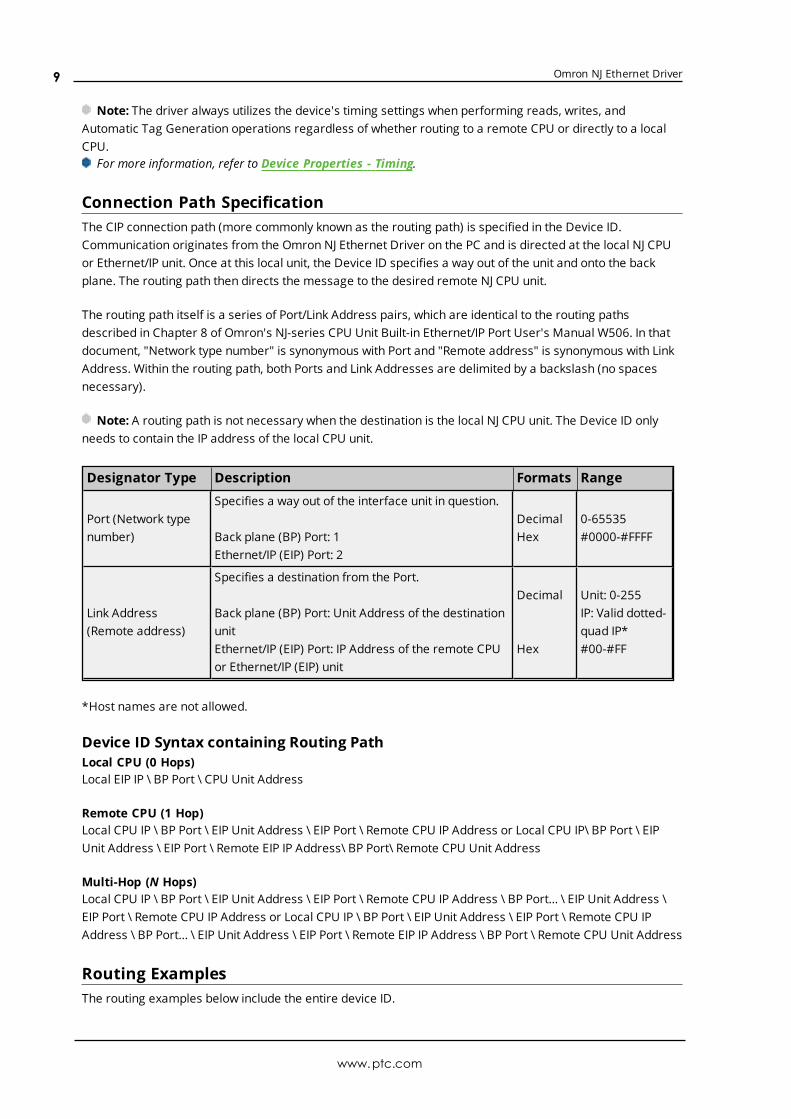
Designator Type Description Formats Range
Port (Network typenumber)
Specifies a way out of the interface unit in question.
Back plane (BP) Port: 1Ethernet/IP (EIP) Port: 2
DecimalHex
0-65535#0000-#FFFF
Link Address(Remote address)
Specifies a destination from the Port.
Back plane (BP) Port: Unit Address of the destinationunitEthernet/IP (EIP) Port: IP Address of the remote CPUor Ethernet/IP (EIP) unit
Decimal
Hex
Unit: 0-255IP: Valid dotted-quad IP*#00-#FF
*Host names are not allowed.
Device ID Syntax containing Routing PathLocal CPU (0 Hops)Local EIP IP \ BP Port \ CPU Unit Address
Remote CPU (1 Hop)Local CPU IP \ BP Port \ EIP Unit Address \ EIP Port \ Remote CPU IP Address or Local CPU IP\ BP Port \ EIPUnit Address \ EIP Port \ Remote EIP IP Address\ BP Port\ Remote CPU Unit Address
Multi-Hop (N Hops)Local CPU IP \ BP Port \ EIP Unit Address \ EIP Port \ Remote CPU IP Address \ BP Port… \ EIP Unit Address \EIP Port \ Remote CPU IP Address or Local CPU IP \ BP Port \ EIP Unit Address \ EIP Port \ Remote CPU IPAddress \ BP Port… \ EIP Unit Address \ EIP Port \ Remote EIP IP Address \ BP Port \ Remote CPU Unit Address
Routing ExamplesThe routing examples below include the entire device ID.
www.ptc.com
9
Omron NJ Ethernet Driver
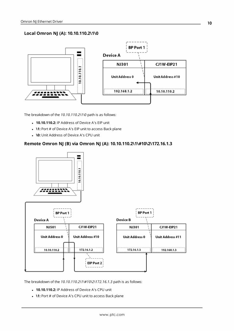
Local Omron NJ (A): 10.10.110.2\1\0
The breakdown of the 10.10.110.2\1\0 path is as follows:
l 10.10.110.2: IP Address of Device A's EIP unit
l \1: Port # of Device A's EIP unit to access Back plane
l \0:Unit Address of Device A's CPU unit
Remote Omron NJ (B) via Omron NJ (A): 10.10.110.2\1\#10\2\172.16.1.3
The breakdown of the 10.10.110.2\1\#10\2\172.16.1.3 path is as follows:
l 10.10.110.2: IP Address of Device A's CPU unit
l \1: Port # of Device A's CPU unit to access Back plane
www.ptc.com
10

Omron NJ Ethernet Driver
l \#10:Unit Address of Device A's EIP unit (10 hex, 16 dec)
l \2: Port # of Device A's EIP unit to access Ethernet/IP
l \172.16.1.3: IP Address of Device B's CPU unit
Remote Omron NJ (B) via Omron NJ (A): 10.10.110.2\1\#10\2\192.168.1.3\1\0
The breakdown of the 10.10.110.2\1\#10\2\192.168.1.3\1\0 path is as follows:
l 10.10.110.2: IP Address of Device A's CPU unit
l \1: Port # of Device A's CPU unit to access Back plane
l \#10:Unit Address of Device A's EIP unit (10 hex, 16 dec)
l \2: Port # of Device A C1J-EIP21 unit to access Ethernet/IP
l 192.168.1.3: IP Address of Device B's EIP unit
l \1: Port # of Device B's EIP unit to access Back plane
l \0:Unit Address of Device B's CPU unit
Remote Omron NJ (C) via Omron NJ (A):10.10.110.2\1\#10\2\192.168.1.3\1\0\2\172.16.1.4\1\0
www.ptc.com
11

Omron NJ Ethernet Driver
The breakdown of the 10.10.110.2\1\#10\2\192.168.1.3\1\0\2\172.16.1.4\1\0 path is as follows:
l 10.10.110.2: IP Address of Device A's CPU unit
l \1: Port # of Device A's CPU unit to access Back plane
l \#10:Unit Address of Device A's EIP unit (10 hex, 16 dec)
l \2: Port # of Device A's EIP unit to access Ethernet/IP
l \192.168.1.3: IP Address of Device B's EIP unit
l \1: Port # of Device B's EIP unit to access Back plane
l \0:Unit Address of Device B's CPU unit
l \2: Port # of Device B's CPU unit to access Ethernet/IP
l \172.16.1.4: IP Address of Device C's EIP unit
l \1: Port # of Device C's EIP unit to access Back plane
l \0:Unit Address of Device C's CPU unit
For more information, refer to Connection Path Specification. For more information on building aconnection/routing path, refer to Chapter 8 of Omron's NJ-series CPU Unit Built-in Ethernet/IP Port User's ManualW506.
Channel PropertiesThis server supports the use of simultaneous multiple communications drivers. Each protocol or driver usedin a server project is called a channel. A server project may consist of many channels with the samecommunications driver or with unique communications drivers. A channel acts as the basic building block ofan OPC link.
www.ptc.com
12

Omron NJ Ethernet Driver
The properties associated with a channel are broken in to logical groupings. While some groups are specificto a given driver or protocol, the following are the common groups:
GeneralEthernet or Serial CommunicationsWrite OptimizationAdvanced
Channel Properties — GeneralThis server supports the use of simultaneous multiple communications drivers. Each protocol or driver usedin a server project is called a channel. A server project may consist of many channels with the samecommunications driver or with unique communications drivers. A channel acts as the basic building block ofan OPC link. This group is used to specify general channel properties, such as the identification attributesand operating mode.
Identification
Name: User-defined identity of this channel. In each server project, each channel name must be unique.Although names can be up to 256 characters, some client applications have a limited display window whenbrowsing the OPC server's tag space. The channel name is part of the OPC browser information.For information on reserved characters, refer to "How To... Properly Name a Channel, Device, Tag, and Tag
Group" in the server help.
Description: User-defined information about this channel. Many of these properties, including Description, have an associated system tag.
Driver: Selected protocol / driver for this channel. This property specifies the device driver that was selectedduring channel creation. It is a disabled setting in the channel properties.
Note: With the server's online full-time operation, these properties can be changed at any time. Thisincludes changing the channel name to prevent clients from registering data with the server. If a client hasalready acquired an item from the server before the channel name is changed, the items are unaffected. If,after the channel name has been changed, the client application releases the item and attempts to re-acquire using the old channel name, the item is not accepted. With this in mind, changes to the propertiesshould not be made once a large client application has been developed. Utilize the User Manager to preventoperators from changing properties and restrict access rights to server features.
Diagnostics
Diagnostics Capture: When enabled, this optionmakes the channel's diagnostic information available toOPC applications. Because the server's diagnostic features require a minimal amount of overheadprocessing, it is recommended that they be utilized when needed and disabled when not. The default isdisabled.
www.ptc.com
13

Omron NJ Ethernet Driver
Note: This property is not available if the driver does not support diagnostics.For more information, refer to "Communication Diagnostics" in the server help.
Channel Properties — Ethernet CommunicationsEthernet Communication can be used to communicate with devices.
Ethernet Settings
Network Adapter: Specify the network adapter to bind. When Default is selected, the operating systemselects the default adapter.
Channel Properties — Write OptimizationsAs with any server, writing data to the device may be the application's most important aspect. The serverintends to ensure that the data written from the client application gets to the device on time. Given this goal,the server provides optimization properties that can be used to meet specific needs or improve applicationresponsiveness.
Write Optimizations
Optimization Method: controls how write data is passed to the underlying communications driver. Theoptions are:
l Write All Values for All Tags: This option forces the server to attempt to write every value to thecontroller. In this mode, the server continues to gather write requests and add them to the server'sinternal write queue. The server processes the write queue and attempts to empty it by writing datato the device as quickly as possible. This mode ensures that everything written from the clientapplications is sent to the target device. This mode should be selected if the write operation order orthe write item's content must uniquely be seen at the target device.
l Write Only Latest Value for Non-Boolean Tags: Many consecutive writes to the same value canaccumulate in the write queue due to the time required to actually send the data to the device. If theserver updates a write value that has already been placed in the write queue, far fewer writes areneeded to reach the same final output value. In this way, no extra writes accumulate in the server'squeue. When the user stops moving the slide switch, the value in the device is at the correct value atvirtually the same time. As the mode states, any value that is not a Boolean value is updated in theserver's internal write queue and sent to the device at the next possible opportunity. This can greatlyimprove the application performance.
Note: This option does not attempt to optimize writes to Boolean values. It allows users to
www.ptc.com
14

Omron NJ Ethernet Driver
optimize the operation of HMI data without causing problems with Boolean operations, such as amomentary push button.
l Write Only Latest Value for All Tags: This option takes the theory behind the second optimizationmode and applies it to all tags. It is especially useful if the application only needs to send the latestvalue to the device. This mode optimizes all writes by updating the tags currently in the write queuebefore they are sent. This is the default mode.
Duty Cycle: is used to control the ratio of write to read operations. The ratio is always based on one read forevery one to ten writes. The duty cycle is set to ten by default, meaning that ten writes occur for each readoperation. Although the application is performing a large number of continuous writes, it must be ensuredthat read data is still given time to process. A setting of one results in one read operation for every writeoperation. If there are no write operations to perform, reads are processed continuously. This allowsoptimization for applications with continuous writes versus a more balanced back and forth data flow.
Note: It is recommended that the application be characterized for compatibility with the writeoptimization enhancements before being used in a production environment.
Channel Properties — AdvancedThis group is used to specify advanced channel properties. Not all drivers support all properties; so theAdvanced group does not appear for those devices.
Non-Normalized Float Handling: A non-normalized value is defined as Infinity, Not-a-Number (NaN), or asa Denormalized Number. The default is Replace with Zero. Drivers that have native float handling maydefault to Unmodified. Non-normalized float handling allows users to specify how a driver handles non-normalized IEEE-754 floating point data. Descriptions of the options are as follows:
l Replace with Zero: This option allows a driver to replace non-normalized IEEE-754 floating pointvalues with zero before being transferred to clients.
l Unmodified: This option allows a driver to transfer IEEE-754 denormalized, normalized, non-number, and infinity values to clients without any conversion or changes.
Note: This property is not available if the driver does not support floating point values or if it only supportsthe option that is displayed. According to the channel's float normalization setting, only real-time driver tags(such as values and arrays) are subject to float normalization. For example, EFM data is not affected by thissetting.
For more information on the floating point values, refer to "How To ... Work with Non-Normalized FloatingPoint Values" in the server help.
Inter-Device Delay: Specify the amount of time the communications channel waits to send new requests tothe next device after data is received from the current device on the same channel. Zero (0) disables thedelay.
Note: This property is not available for all drivers, models, and dependent settings.
www.ptc.com
15

Omron NJ Ethernet Driver
Driver Device PropertiesDevice properties are organized into groups. Click on a link below for details about the settings in that group.
GeneralScan ModeTimingAuto-DemotionTag GenerationCommunication ParametersOptionsRedundancy
Device Properties — General
Identification
Name: User-defined identity of this device.
Description: User-defined information about this device.
Channel Assignment: User-defined name of the channel to which this device currently belongs.
Driver: Selected protocol driver for this device.
Model: The specific version of the device. For a list of models that support the FINS Communications Service,refer to the manufacturer's website.
ID: The ID specifies the path to the destination NJ CPU unit.
l The device ID for a local NJ CPU unit is specified as the IP or host name of the local CPU unit. It mustbe a valid dotted-quad IP Address or host name. For example, "192.168.1.100" or "NJ001".
l The device ID for a remote NJ CPU unit is specified as the IP or host name of the local CPU orEthernet/IP unit plus a CIP Connection Path (also known as Routing Path) to the remote CPU unit. Forexample, "192.168.1.100\1\#10\2\10.10.110.2".
For information on connection path syntax, refer to Connection Path Specification.
Operating Mode
www.ptc.com
16

Omron NJ Ethernet Driver
Data Collection: This property controls the device's active state. Although device communications areenabled by default, this property can be used to disable a physical device. Communications are notattempted when a device is disabled. From a client standpoint, the data is marked as invalid and writeoperations are not accepted. This property can be changed at any time through this property or the devicesystem tags.
Simulated: This option places the device into Simulation Mode. In this mode, the driver does not attempt tocommunicate with the physical device, but the server continues to return valid OPC data. Simulated stopsphysical communications with the device, but allows OPC data to be returned to the OPC client as valid data.While in Simulation Mode, the server treats all device data as reflective: whatever is written to the simulateddevice is read back and each OPC item is treated individually. The item's memory map is based on the groupUpdate Rate. The data is not saved if the server removes the item (such as when the server is reinitialized).The default is No.
Notes:
1. This System tag (_Simulated) is read only and cannot be written to for runtime protection. The Systemtag allows this property to be monitored from the client.
2. In Simulationmode, the item's memory map is based on client update rate(s) (Group Update Rate forOPC clients or Scan Rate for native and DDE interfaces). This means that two clients that referencethe same item with different update rates return different data.
Simulation Mode is for test and simulation purposes only. It should never be used in a productionenvironment.
Device Properties — Scan ModeThe ScanMode specifies the subscribed-client requested scan rate for tags that require devicecommunications. Synchronous and asynchronous device reads and writes are processed as soon aspossible; unaffected by the ScanMode properties.
Scan Mode: specifies how tags in the device are scanned for updates sent to subscribing clients.Descriptions of the options are:
l Respect Client-Specified Scan Rate: This mode uses the scan rate requested by the client.l Request Data No Faster than Scan Rate: This mode specifies the maximum scan rate to be used.
The valid range is 10 to 99999990 milliseconds. The default is 1000 milliseconds.Note: When the server has an active client and items for the device and the scan rate value is
increased, the changes take effect immediately. When the scan rate value is decreased, the changesdo not take effect until all client applications have been disconnected.
l Request All Data at Scan Rate: This mode forces tags to be scanned at the specified rate forsubscribed clients. The valid range is 10 to 99999990 milliseconds. The default is 1000 milliseconds.
l Do Not Scan, Demand Poll Only: This mode does not periodically poll tags that belong to thedevice nor perform a read to get an item's initial value once it becomes active. It is the client'sresponsibility to poll for updates, either by writing to the _DemandPoll tag or by issuing explicit devicereads for individual items. For more information, refer to "Device Demand Poll" in server help.
www.ptc.com
17

Omron NJ Ethernet Driver
l Respect Tag-Specified Scan Rate: This mode forces static tags to be scanned at the rate specifiedin their static configuration tag properties. Dynamic tags are scanned at the client-specified scanrate.
Initial Updates from Cache: When enabled, this option allows the server to provide the first updates fornewly activated tag references from stored (cached) data. Cache updates can only be provided when thenew item reference shares the same address, scan rate, data type, client access, and scaling properties. Adevice read is used for the initial update for the first client reference only. The default is disabled; any time aclient activates a tag reference the server attempts to read the initial value from the device.
Device Properties — TimingThe device Timing properties allow the driver's response to error conditions to be tailored to fit theapplication's needs. In many cases, the environment requires changes to these properties for optimumperformance. Factors such as electrically generated noise, modem delays, and poor physical connectionscan influence howmany errors or timeouts a communications driver encounters. Timing properties arespecific to each configured device.
Communications Timeouts
Connect Timeout: This property (which is used primarily by Ethernet based drivers) controls the amount oftime required to establish a socket connection to a remote device. The device's connection time often takeslonger than normal communications requests to that same device. The valid range is 1 to 30 seconds. Thedefault is typically 3 seconds, but can vary depending on the driver's specific nature. If this setting is notsupported by the driver, it is disabled.
Note: Due to the nature of UDP connections, the connection timeout setting is not applicable whencommunicating via UDP.
Request Timeout: This property specifies an interval used by all drivers to determine how long the driverwaits for a response from the target device to complete. The valid range is 50 to 9,999,999 milliseconds(167.6667 minutes). The default is usually 1000 milliseconds, but can vary depending on the driver. Thedefault timeout for most serial drivers is based on a baud rate of 9600 baud or better. When using a driverat lower baud rates, increase the timeout to compensate for the increased time required to acquire data.
Attempts Before Timeout: This property specifies howmany times the driver issues a communicationsrequest before considering the request to have failed and the device to be in error. The valid range is 1 to10. The default is typically 3, but can vary depending on the driver's specific nature. The number of attemptsconfigured for an application depends largely on the communications environment. This property applies toboth connection attempts and request attempts.
Timing
www.ptc.com
18
Omron NJ Ethernet Driver
Inter-Request Delay: This property specifies how long the driver waits before sending the next request tothe target device. It overrides the normal polling frequency of tags associated with the device, as well asone-time reads and writes. This delay can be useful when dealing with devices with slow turnaround timesand in cases where network load is a concern. Configuring a delay for a device affects communications withall other devices on the channel. It is recommended that users separate any device that requires an inter-request delay to a separate channel if possible. Other communications properties (such as communicationserialization) can extend this delay. The valid range is 0 to 300,000 milliseconds; however, some drivers maylimit the maximum value due to a function of their particular design. The default is 0, which indicates nodelay between requests with the target device.
Note: Not all drivers support Inter-Request Delay. This setting does not appear if it is not available.
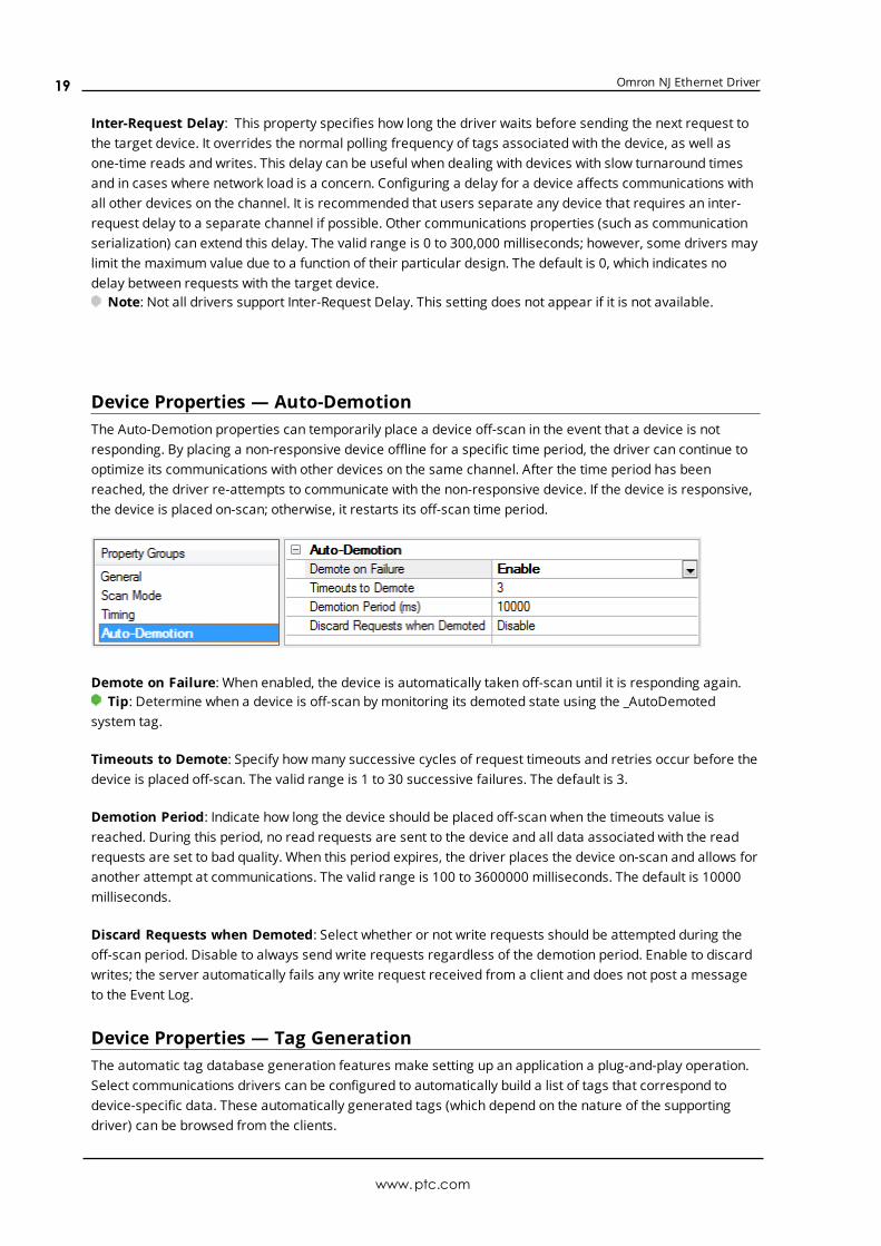
Device Properties — Auto-DemotionThe Auto-Demotion properties can temporarily place a device off-scan in the event that a device is notresponding. By placing a non-responsive device offline for a specific time period, the driver can continue tooptimize its communications with other devices on the same channel. After the time period has beenreached, the driver re-attempts to communicate with the non-responsive device. If the device is responsive,the device is placed on-scan; otherwise, it restarts its off-scan time period.
Demote on Failure: When enabled, the device is automatically taken off-scan until it is responding again.Tip: Determine when a device is off-scan by monitoring its demoted state using the _AutoDemoted
system tag.
Timeouts to Demote: Specify howmany successive cycles of request timeouts and retries occur before thedevice is placed off-scan. The valid range is 1 to 30 successive failures. The default is 3.
Demotion Period: Indicate how long the device should be placed off-scan when the timeouts value isreached. During this period, no read requests are sent to the device and all data associated with the readrequests are set to bad quality. When this period expires, the driver places the device on-scan and allows foranother attempt at communications. The valid range is 100 to 3600000 milliseconds. The default is 10000milliseconds.
Discard Requests when Demoted: Select whether or not write requests should be attempted during theoff-scan period. Disable to always send write requests regardless of the demotion period. Enable to discardwrites; the server automatically fails any write request received from a client and does not post a messageto the Event Log.
Device Properties — Tag GenerationThe automatic tag database generation features make setting up an application a plug-and-play operation.Select communications drivers can be configured to automatically build a list of tags that correspond todevice-specific data. These automatically generated tags (which depend on the nature of the supportingdriver) can be browsed from the clients.
www.ptc.com
19

Omron NJ Ethernet Driver
Not all devices and drivers support full automatic tag database generation and not all support the same datatypes. Consult the data types descriptions or the supported data type lists for each driver for specifics.
If the target device supports its own local tag database, the driver reads the device's tag information anduses the data to generate tags within the server. If the device does not natively support named tags, thedriver creates a list of tags based on driver-specific information. An example of these two conditions is asfollows:
1. If a data acquisition system supports its own local tag database, the communications driver uses thetag names found in the device to build the server's tags.
2. If an Ethernet I/O system supports detection of its own available I/Omodule types, thecommunications driver automatically generates tags in the server that are based on the types of I/Omodules plugged into the Ethernet I/O rack.
Note: Automatic tag database generation's mode of operation is completely configurable. For moreinformation, refer to the property descriptions below.
On Property Change: If the device supports automatic tag generation when certain properties change, theOn Property Change option is shown. It is set to Yes by default, but it can be set toNo to control over whentag generation is performed. In this case, the Create tags actionmust be manually invoked to perform taggeneration.
On Device Startup: This property specifies when OPC tags are automatically generated. Descriptions of theoptions are as follows:
l Do Not Generate on Startup: This option prevents the driver from adding any OPC tags to the tagspace of the server. This is the default setting.
l Always Generate on Startup: This option causes the driver to evaluate the device for taginformation. It also adds tags to the tag space of the server every time the server is launched.
l Generate on First Startup: This option causes the driver to evaluate the target device for taginformation the first time the project is run. It also adds any OPC tags to the server tag space asneeded.
Note: When the option to automatically generate OPC tags is selected, any tags that are added to theserver's tag space must be saved with the project. Users can configure the project to automatically savefrom the Tools | Optionsmenu.
On Duplicate Tag: When automatic tag database generation is enabled, the server needs to know what todo with the tags that it may have previously added or with tags that have been added or modified after thecommunications driver since their original creation. This setting controls how the server handles OPC tagsthat were automatically generated and currently exist in the project. It also prevents automaticallygenerated tags from accumulating in the server.
www.ptc.com
20

Omron NJ Ethernet Driver
For example, if a user changes the I/Omodules in the rack with the server configured to Always Generateon Startup, new tags would be added to the server every time the communications driver detected a newI/Omodule. If the old tags were not removed, many unused tags could accumulate in the server's tag space.The options are:
l Delete on Create: This option deletes any tags that were previously added to the tag space beforeany new tags are added. This is the default setting.
l Overwrite as Necessary: This option instructs the server to only remove the tags that thecommunications driver is replacing with new tags. Any tags that are not being overwritten remain inthe server's tag space.
l Do not Overwrite: This option prevents the server from removing any tags that were previouslygenerated or already existed in the server. The communications driver can only add tags that arecompletely new.
l Do not Overwrite, Log Error: This option has the same effect as the prior option, and also posts anerror message to the server's Event Log when a tag overwrite would have occurred.
Note: Removing OPC tags affects tags that have been automatically generated by thecommunications driver as well as any tags that have been added using names that match generatedtags. Users should avoid adding tags to the server using names that may match tags that areautomatically generated by the driver.
Parent Group: This property keeps automatically generated tags frommixing with tags that have beenenteredmanually by specifying a group to be used for automatically generated tags. The name of the groupcan be up to 256 characters. This parent group provides a root branch to which all automatically generatedtags are added.
Allow Automatically Generated Subgroups: This property controls whether the server automaticallycreates subgroups for the automatically generated tags. This is the default setting. If disabled, the servergenerates the device's tags in a flat list without any grouping. In the server project, the resulting tags arenamed with the address value. For example, the tag names are not retained during the generation process.
Note: If, as the server is generating tags, a tag is assigned the same name as an existing tag, the systemautomatically increments to the next highest number so that the tag name is not duplicated. For example, ifthe generation process creates a tag named "AI22" that already exists, it creates the tag as "AI23" instead.
Create: Initiates the creation of automatically generated OPC tags. If the device's configuration has beenmodified, Create tags forces the driver to reevaluate the device for possible tag changes. Its ability to beaccessed from the System tags allows a client application to initiate tag database creation.
Note: Create tags is disabled if the Configuration edits a project offline.
Device Properties — Communications Parameters
www.ptc.com
21
Omron NJ Ethernet Driver
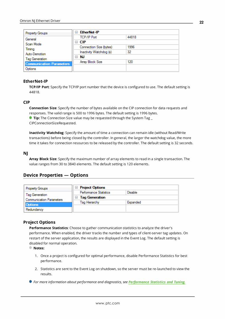
EtherNet-IPTCP/IP Port: Specify the TCP/IP port number that the device is configured to use. The default setting is44818.
CIPConnection Size: Specify the number of bytes available on the CIP connection for data requests andresponses. The valid range is 500 to 1996 bytes. The default setting is 1996 bytes.
Tip: The Connection Size value may be requested through the System Tag _CIPConnectionSizeRequested.
Inactivity Watchdog: Specify the amount of time a connection can remain idle (without Read/Writetransactions) before being closed by the controller. In general, the larger the watchdog value, the moretime it takes for connection resources to be released by the controller. The default setting is 32 seconds.
NJArray Block Size: Specify the maximum number of array elements to read in a single transaction. Thevalue ranges from 30 to 3840 elements. The default setting is 120 elements.
Device Properties — Options
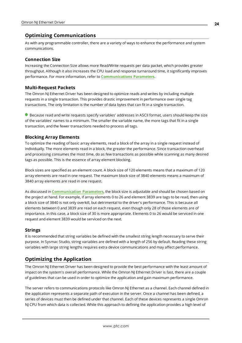
Project OptionsPerformance Statistics: Choose to gather communication statistics to analyze the driver'sperformance. When enabled, the driver tracks the number and types of client-server tag updates. Onrestart of the server application, the results are displayed in the Event Log. The default setting isdisabled for normal operation.
Notes:
1. Once a project is configured for optimal performance, disable Performance Statistics for bestperformance.
2. Statistics are sent to the Event Log on shutdown, so the server must be re-launched to view theresults.
For more information about performance and diagnostics, see Performance Statistics and Tuning.
www.ptc.com
22

Omron NJ Ethernet Driver
Tag GenerationTag Hierarchy: Select how the tag hierarchy appears. The default setting is Expanded.
l Condensed In this mode, the server tags created by automatic tag generation follow agroup/tag hierarchy consistent with the tag's address. Groups are created for everysegment preceding the period.
l Expanded In ExpandedMode, tag groups are created for every segment preceding theperiod (as in CondensedMode), but groups are also created for array tags. This is thedefault setting.
For more information on how groups are created, refer to Tag Hierarchy.
Tip: To use this functionality, enable Allow Sub Groups.
Device Properties — Redundancy
Redundancy is available with the Media-Level Redundancy Plug-In.Consult the website, a sales representative, or the user manual for more information.
www.ptc.com
23
Omron NJ Ethernet Driver
Optimizing CommunicationsAs with any programmable controller, there are a variety of ways to enhance the performance and systemcommunications.
Connection SizeIncreasing the Connection Size allows more Read/Write requests per data packet, which provides greaterthroughput. Although it also increases the CPU load and response turnaround time, it significantly improvesperformance. For more information, refer to Communications Parameters.
Multi-Request PacketsThe Omron NJ Ethernet Driver has been designed to optimize reads and writes by including multiplerequests in a single transaction. This provides drastic improvement in performance over single tagtransactions. The only limitation is the number of data bytes that can fit in a single transaction.
Because read and write requests specify variables' addresses in ASCII format, users should keep the sizeof the variables' names to a minimum. The smaller the variable name, the more tags that fit in a singletransaction, and the fewer transactions needed to process all tags.
Blocking Array ElementsTo optimize the reading of basic array elements, read a block of the array in a single request instead ofindividually. The more elements read in a block, the greater the performance. Since transaction overheadand processing consumes the most time, do as few transactions as possible while scanning as many desiredtags as possible. This is the essence of array element blocking.
Block sizes are specified as an element count. A block size of 120 elements means that a maximum of 120array elements are read in one request. The maximum block size of 3840 elements means a maximum of3840 array elements are read in one request.
As discussed in Communication Parameters, the block size is adjustable and should be chosen based onthe project at hand. For example, if array elements 0 to 26 and element 3839 are tags to be read, then usinga block size of 3840 is not only overkill, but detrimental to the driver's performance. This is because allelements between 0 and 3839 are read on each request, even though only 28 of those elements are ofimportance. In this case, a block size of 30 is more appropriate. Elements 0 to 26 would be serviced in onerequest and element 3839 would be serviced on the next.
StringsIt is recommended that string variables be defined with the smallest string length necessary to serve theirpurpose. In Sysmac Studio, string variables are defined with a length of 256 by default. Reading these stringvariables with large string lengths requires extra device communications andmay affect performance.
Optimizing the ApplicationThe Omron NJ Ethernet Driver has been designed to provide the best performance with the least amount ofimpact on the system's overall performance. While the Omron NJ Ethernet Driver is fast, there are a coupleof guidelines that can be used in order to optimize the application and gain maximum performance.
The server refers to communications protocols like Omron NJ Ethernet as a channel. Each channel defined inthe application represents a separate path of execution in the server. Once a channel has been defined, aseries of devices must then be defined under that channel. Each of these devices represents a single OmronNJ CPU from which data is collected. While this approach to defining the application provides a high level of
www.ptc.com
24

Omron NJ Ethernet Driver
performance, it doesn't take full advantage of the Omron NJ Ethernet Driver or the network. An example ofhow the applicationmay appear when configured using a single channel is shown below.
Each device appears under a single channel, called "Channel1". In this configuration, thedriver must move from one device to the next as quickly as possible in order to gatherinformation at an effective rate. As more devices are added or more information isrequested from a single device, the overall update rate begins to suffer.
If the Omron NJ Ethernet Driver could only define one channel, then all devices needed for the project wouldhave to be created beneath it; however, the driver can define up to 256 channels. Using multiple channelsdistributes the data collection workload by simultaneously issuing multiple requests to the network. Anexample of how the same applicationmay appear when configured using multiple channels to improveperformance is shown below.
Each device has now been defined under its own channel. In this new configuration, asingle path of execution is dedicated to the task of gathering data from each device. Ifthe application has 256 or fewer devices, it can be optimized exactly how it is shownhere.
The performance improves even if the application has more than 256 devices. While 256or fewer devices may be ideal, the application benefits from additional channels.Although spreading the device load across all channels causes the server to move fromdevice to device again, it can now do so with far less devices to process on a singlechannel.
Performance Statistics and TuningThe Performance Statistics feature provides benchmarks and statistics about the Omron NJ Ethernetapplication's performance. It can affect the server's performance because it is an additional layer ofprocessing. As such, it is disabled by default. To use the Performance Statistics feature, access the deviceproperties and expand the Options group. For Performance Statistics, select Enable.
Types of Performance StatisticsPerformance Statistics provide meaningful numerical results across three scopes: device, channel, anddriver. Descriptions of the types are as follows:
l Device: These statistics provide the data access performance on a particular device.
l Channel: These statistics provide the average data access performance for all the devices under agiven channel with Performance Statistics enabled.
l Driver: These statistics provide the average data access performance for all devices using theOmron NJ Ethernet Driver with Performance Statistics enabled.
Choosing a Statistic TypeThe type of statistics needed depends on the application. In general, driver statistics provide a true measureof the application's performance, whereas channel and device statistics are most relevant while tuning theapplication. For example, moving 10 certain tags from Device A to Device B may increase the performanceof Device A. Moving Device A from Channel 1 to Channel 2 may increase the performance of Channel 1.These are good examples of situations when device and channel statistics should be used.
Locating Statistics
www.ptc.com
25
Omron NJ Ethernet Driver
Server statistics are outputted to the server's Event Log upon shutdown. To view the results, shut down theserver and then restart it.
Differences between Server Statistics and Performance StatisticsPerformance Statistics provide the makeup of the types of reads performed (such as device reads vs. cachereads) whereas server statistics provide a general read count value.
Tuning the Application for Increased PerformanceTo increase device and channel statistic results, keep variable names to a minimum length and use VariableArrays as often as possible. For more information, refer toOptimizing Communications.
For information on increasing driver statistic results, refer to the instructions below. For more information,refer toOptimizing the Application.
1. Devices should be spread across channels. More than one device should not be put on a channelunless necessary.
2. Load should be spread evenly across devices. A single device should not be overloaded unlessnecessary.
3. The same Variable Tag should not be referenced across different devices.
www.ptc.com
26

Omron NJ Ethernet Driver
Data Type Descriptions
Data Type Description
Boolean Single bit
Byte Unsigned 8-bit value
Char Signed 8-bit value
Word
Unsigned 16-bit value
bit 0 is the low bitbit 15 is the high bit
Short
Signed 16-bit value
bit 0 is the low bitbit 14 is the high bitbit 15 is the sign bit
Long Signed 32-bit value
DWord Unsigned 32-bit value
Float 32-bit IEEE floating point
Double 64-bit IEEE floating point
Date 64-bit date and time value
String Null-terminated Unicode string
Default *
*If the data type is specified as "Default" when creating a Static Tag, the driver queries the controller for thetag's data type and sets the canonical data type for items referencing that Static Tag to the query result. If adata type is not specified when creating a Dynamic Tag, the driver queries the controller for the tag's datatype and sets the canonical data type for that Dynamic Tag to the query result.
www.ptc.com
27

Omron NJ Ethernet Driver
Address DescriptionsThe Omron NJ Ethernet Driver uses a tag or symbol-based addressing structure referred to as variables.These tags differ from conventional PLC data items in that the tag name itself is the address, not a file orregister number. Users can access the controller's basic data types. Although some of the system-definedtypes are structures, they are ultimately based on these basic data types. Thus, all basic members of astructure are accessible.
OmronData Type
DescriptionDataType
Range
BOOLSingle bitvalue
Boolean 0, 1
SINTSigned 8-bitvalue
Char -128 to 127
USINTUnsigned 8-bit value
Byte 0 to 255
BYTEBit string (8bits)
Byte 0 to 255
INTSigned 16-bitvalue
Short -32768 to 32767
UINTUnsigned 16-bit value
Word 0 to 65535
WORDBit string (16bits)
Word 0 to 65535
DINTSigned 32-bitvalue
Long -2147483648 to 2147483647
UDINTUnsigned 32-bit value
DWord 0 to 4294967295
DWORDBit string (32bits)
DWord 0 to 4294967295
LINTSigned 64-bitvalue
Double -9223372036854775808 to 9223372036854775807
ULINTUnsigned 64-bit value
Double 0 to 18446744073709551615
REAL32-bit IEEEfloating point
Float-3.402823e+38 to -1.175495e-3801.175495e-38 to 3.402823e+38
LREAL64-bit IEEEfloating point
Double-1.79769313486231e+308 to -2.22507385850721e-30802.22507385850721e-308 to 1.79769313486231e+308
DATE ANDTIME
Unsigned 64-bit value
DateThe date/time variable format is: YYYY-MM-DDTHH:MM:SS.MS.The supported range is 1970-01-01T00:00:00.000 to 2106-02-06T23:59:59.999.
STRINGCharacterstring
String
String lengths range from 1 to 1985 characters. This equates tovariables defined in Sysmac Studio as STRING[2] and STRING[1986] respectively. The extra character accounts for the nullterminator.
www.ptc.com
28

Omron NJ Ethernet Driver
OmronData Type
DescriptionDataType
Range
EnumerationSigned 32-bitvalue
Long -2147483648 to 2147483647*
*The valid values for an enumeration are actually a subset of the values in the specified range. The subsetof values is determined by the configuration of the enumeration in the Omron NJ device.
Client/Server Tag Address RulesVariable names correspond to Client/Server Tag addresses. Both variable names and Client/Server Tagaddresses follow the IEC 61131-3 identifier rules. Descriptions of the rules are as follows:
l Can only contain alphanumeric characters and underscores
l Can have as many as 127 characters per segment
l Characters are not case sensitive
l White spaces are ignored
Client/Server Tag Name RulesTag name assignment in the server differs from address assignment in that names cannot begin with anunderscore. For syntax and examples, refer to Address Formats.
Important: If a tag address is large enough that it exceeds the protocol limit of 511 bytes, it will failvalidation with an "Address out of range" error. If this occurs, reduce the number of characters in the tagaddress until it passes validation.
Data Type CoercionThe Omron NJ Ethernet Driver can coerce some Omron data types in the controller to more than one serverdata type. For example, the tag for a SINT variable in the controller can be created with a Byte server datatype. For a list of the supported data type coercions for all Omron data types that are supported by thedriver, refer to the table below.
Omron Data Type Data Type
BOOL Boolean
SINT, USINT, OR BYTE Char or Byte
INT, UINT, ORWORD Short or Word
DINT, UDINT, DWORD, OR ENUM Long or DWord
LINT OR ULINT Double
REAL Float
LREAL Double
DATE AND TIME Date
STRING String
Address FormatsA Variable Tag may be addressed statically in the server or dynamically from a client in several ways. Thetag's format depends on its type and intended usage. Descriptions of the variable types are as follows:
www.ptc.com
29

Omron NJ Ethernet Driver
l Array Element: A variable may be defined in the controller using the following syntax: ARRAY [x1..x2,y1..y2, z1..z2] OF TYPE, where TYPE is one of the Omron data types listed in Address Descriptions. Toaccess individual elements, specify the x, y, and z offsets. The driver blocks read requests on the lastdimension. For example, with a variable like "MyArray[1,0]" and "MyArray[1,4]," the driver performsa single request for five elements starting at "MyArray[1,0]." For more information, refer toCommunication Parameters andOptimizing Communications.
l Array: A variable may be defined in the controller using the following syntax: ARRAY [x1..x2, y1..y2,z1..z2] OF TYPE, where TYPE is one of the Omron data types listed in Address Descriptions. To accessmultiple elements in a single client item, use the array type syntax. Like Array Elements, the driverperforms a single request to read and write multiple array elements. The difference with arrays isthat all items in the array is provided to the client in an atomic operation. String Arrays are notsupported.
Note:Not all clients support array types. For support information, refer to the client application.
l Basic: A variable defined with a basic type and no array syntax.
l String: A variable defined with the string basic type.
Tip: All Symbolic Variable Tag names in Sysmac Studio can be copied and pasted into the server's tagaddress field and be valid.
Array ElementAt least one dimension (but no more than three) must be specified.
Syntax Example
<Variable Tag name> [dim1] tag_1 [5]
<Variable Tag name> [dim 1, dim2] tag_1 [2, 3]
<Variable Tag name> [dim 1, dim2, dim 3] tag_1 [2, 58, 547]
ExamplesMyBooleanArray[31]MyBooleanArray3D[2,2,7]MySintArray[1]MyLrealArray[65535]MySintArray2D[1,2]MyLrealArray2D[2,500]MySintArray3D[2,3,9]MyLrealArray3D[2,10,10]
ArrayWith this format, multiple elements of a Variable Array are read and written in a single transaction. Theclient must support array types (such as "VT_ARRAY"). Client data is organized in a row by column format tofacilitate one dimension (1 row, y columns) or two dimensions (x rows, y columns). This format is supportedfor one-dimensional, two-dimensional, and three-dimensional Variable Arrays only. Like Array Elements, atleast one dimension (but no more than three) must be specified.
Note: All Omron data types that are supported by this driver support the array format except string anddate and time.
Important: Spanning an array across multiple Variable Array dimensions is not supported. If an array iscreated on a two-dimensional or three-dimensional Variable Array, the size of that array (which is rows by
www.ptc.com
30

Omron NJ Ethernet Driver
columns) must not exceed the bounds of the last dimension. For example, given a Variable Array"MySintArray3D" defined as ARRAY[0..2,0..3,0..9] OF SINT, the Array Tag MySintArray3D[0,0,0]{10} is validbecause it references elements [0,0,0..9] that all lie within the last dimension. MySintArray3D[0,0,0]{11} isinvalid, however, because it is attempting to reference elements [0,0,0..9] and [0,1,0] that exceed the boundsof the last dimension by one element.
Syntax Example
<Variable Tag name> [dim 1 offset] {# of columns} tag_1 [5]{8}
<Variable Tag name> [dim 1 offset, dim 2 offset] {# of columns} tag_2 [0, 5]{8}
<Variable Tag name> [dim 1 offset, dim 2 offset, dim 3 offset] {# of columns} tag_3 [1,0, 5]{8}
<Variable Tag name> [dim 1 offset] {# of rows}{# of columns} tag_4 [5]{2}{4}
<Variable Tag name> [dim 1 offset, dim 2 offset] {# of rows}{# of columns} tag_1 [0,5]{2}{4}
<Variable Tag name> [dim 1 offset, dim 2 offset, dim 3 offset] {# of rows}{# ofcolumns}
tag_1 [1,0,5]{2}{4}
Note: The number of elements to read and/or write equals the number of rows multiplied by the numberof columns. If no rows are specified, the number of rows defaults to 1. At least one element of the arraymust be addressed. Rows x Columns must be between 1 and 65535.
ExamplesMyBooleanArray[0]{32}MyBooleanArray3D[2,2,7]{1}MySintArray[1]{5}MyLrealArray[65535]{1}MySintArray2D[1,2]{10}MyLrealArray2D[2,500]{14}{20}MySintArray3D[2,3,9]{10}MyLrealArray3D[2,10,10]{14}{20}
BasicSyntax Example
<Variable Tag name> tag_1
ExamplesMyBoolMyByteMyIntMyWordMyReal
StringThe number of characters to read and/or write equals the string length, which must be at least 2. AlthoughSysmac Studio allows a variable to be defined as STRING [1], reads and writes are not possible because onecharacter is reserved for a null terminator. As such, it is recommended that string variables be defined witha length of 2 to 1986. To account for this null terminator, the valid range for string lengths in the driver is 1 to1985. Strings support any character encoded in UTF-8. One UTF-8 character can equal 1 to 4 bytes.
Note: A 256 byte string containing characters that require multiple bytes when encoded in UTF-8represents fewer than 256 characters.
www.ptc.com
31

Omron NJ Ethernet Driver
Syntax Example
<Variable Tag name> / <string length> tag_1 / 255
ExamplesMyString256/255MyString1986/1985MyString1986/100MyStruct[23].Banners[4].Output/10MyStringArray3D[2,10,10]/255
Tag ScopeNote: Local variables can only be read and written in a POU (program, function, or function block) in which
it is defined.
Global TagsGlobal Tags are Variable Tags that have global scope in the controller. Any program or task can accessGlobal Tags; however, the number of ways a Global Tag can be referenced depends on both its VariableData Type and the address format being used.
Structure Tag AddressingStructure Tags are tags with one or more member tags, which can be basic or structured in nature.
<structure name> . <basic-type tag>
This implies that a substructure would be addressed as:
<structure name> . <substructure name> .<basic-type tag>
Arrays of structures would be addressed as follows:
<structure array name> [dim1, dim2, dim3] . <basic-type tag>
Again, this implies that an array of substructures would be addressed as:
<structure name> . <substructure array name> [dim1, dim2, dim3] . <basic-type tag>
Note: The examples given above are only a few of the many addressing possibilities involving structures.They are displayed in order to provide an introduction to structure addressing.
For more information, refer to Omron NJ documentation.
Predefined Term TagsThe tags displayed in the table below can be used to obtain general processor information from a PLC.
Tag NameDataType
Description
#DEVICETYPE Word An integer value that corresponds to the "ProdType" attribute specified inthe PLC's EDS file.
#REVISION String Firmware revision displayed as <major>.<minor>.
www.ptc.com
32

Omron NJ Ethernet Driver
Tag NameDataType
Description
#PRODUCTNAME String The processor name that corresponds to the "ProdName" attributespecified in the PLC's EDS file.
#PRODUCTCODE Word An integer value that corresponds to the "ProdCode" attribute specified inthe PLC's EDS file.
#VENDORID Word An integer value that corresponds to the "VendCode" attribute specified inthe PLC's EDS file.
www.ptc.com
33

Omron NJ Ethernet Driver
Automatic Tag Database GenerationThe Omron NJ Ethernet Driver can be configured to automatically generate a list of tags within the serverthat correspond to the Global Variables used in the Omron SYSMAC NJ Series controller program and thatare published to the network as inputs, outputs, or publish-only variables.
To generate tags from the device:
1. In the Configuration, select the device for which tags should be generated.
2. Right-click and select Properties... to open the device properties.
3. Locate and expand the Tag Generation section.
4. Locate the Create property. The Value is blue text that reads Create tags.
5. Click the Create tags text to initiate tag database creation.
6. Click the Close button to exit the dialog box.
7. Check the Event Log for messages confirming successful generation.
For more information about custom settings, see the server help file.
Notes:
1. It is recommended that all communications to the Omron NJ device cease during tag databasecreation process.
2. Variable tags generated for enumerations are data type Long.
See Also: Address Formats and Address Descriptions.
Tag HierarchyThe tags created by automatic tag generation can follow one of two hierarchies: Expanded or Condensed. Toenable this functionality, ensure that Allow Sub Groups is enabled in device properties. The default setting isExpanded.
Expanded ModeIn ExpandedMode, tag groups are created for every segment preceding the period (as in CondensedMode),but are also created in logical groupings. Groups created include the following:
l Structures and substructures
l Unions
l Arrays
Basic Global tags (or non-structure, non-union, and non-array tags) are placed at the device level. Eachstructure, union, and array tag is provided in its own subgroup of the parent group.
The name of the structure, union, or array subgroup also provides a description of the structure, union, orarray. For example, an array tag1[1,6] defined in the controller would have a subgroup name of "tag1[x,y]"where x signifies dimension 1 exists and y signifies dimension 2 exists. The tags within an array subgroupare all the elements of that array. The tags within a structure subgroup are the structure membersthemselves. If a structure contains an array, then an array subgroup of the structure group is created aswell. The tags within a union subgroup are the unionmembers themselves. If a union contains an array, thenan array subgroup of the union group is created as well.
www.ptc.com
34

Omron NJ Ethernet Driver
Array Tag GroupsA group is created for each array that contains array elements. Group names have the notation: <arrayname>[x,y,z] where:
l [x,y,z] is a 3 dimensional array
l [x,y] is a 2 dimensional array
l [x] is a 1 dimensional array
Array Tags have the notation: <tag element>[XXXXX,YYYYY,ZZZZZ]. For example, element tag1[12,2,987] wouldhave the tag name "tag1[12,2,987]".
Condensed ModeIn CondensedMode, the server tags created by automatic tag generation follow a group/tag hierarchyconsistent with the tag's address. Groups are created for every segment preceding the period. Groupscreated include the following:
l Structures and substructures
l Unions
Note:Groups are not created for arrays.
www.ptc.com
35

Omron NJ Ethernet Driver
Event Log MessagesThe following information concerns messages posted to the Event Log pane in the main user interface.Consult the server help on filtering and sorting the Event Log detail view. Server help contains manycommonmessages, so should also be searched. Generally, the type of message (informational, warning)and troubleshooting information is provided whenever possible.
Internal error occurred while attempting to write tag. Unexpected datatype. | Tag address = '<address>', Data type = '<type>', DTRV = <code>.Error Type:Error
The following errors occurred uploading controller project from device.Resorting to symbolic protocol.Error Type:Error
Possible Cause:The device returned an error within the CIP portion of the Ethernet/IP packet during an automatic taggeneration request.
Possible Solution:The solution depends on the error codes returned.
See Also:CIP Error Codes
Unknown error occurred.Error Type:Error
Low memory resources.Error Type:Error
Invalid or corrupt controller project detected while synchronizing.Synchronization will be retried shortly.Error Type:Error
Project download detected while synchronizing. Synchronization will beretried shortly.Error Type:
www.ptc.com
36

Omron NJ Ethernet Driver
Error
Encapsulation error occurred while uploading project information. |Encapsulation error = <code>.Error Type:Error
Possible Cause:The device returned an error within the encapsulation portion of the Ethernet/IP packet during an automatictag generation request.
Possible Solution:The driver attempts to recover from this error.
Note:This excludes error 0x02, which is device-related and not driver-related.
Error occurred while uploading project information. | CIP error = <code>,Extended error = <code>.Error Type:Error
Possible Cause:The device returned an error within the CIP portion of the Ethernet/IP packet during an automatic taggeneration request.
Possible Solution:The solution depends on the error codes returned.
See Also:CIP Error Codes
Framing error occurred while uploading project information.Error Type:Error
Possible Cause:
1. The packets are misaligned due to the connection or disconnection between the PC and device.
2. There is bad cabling connecting the device causing noise.
Possible Solution:
1. Place the device on less noisy network.
2. Increase the Request Timeout and/or Request Attempts.
www.ptc.com
37
Omron NJ Ethernet Driver
CIP connection timed-out while uploading project information.Error Type:Error
Database error. CIP connection timed-out while uploading projectinformation.Error Type:Error
Database error. Error occurred while uploading project information. | CIPerror = <code>, Extended error = <code>.Error Type:Error
Possible Cause:The device returned an error within the CIP portion of the Ethernet/IP packet during an automatic taggeneration request.
Possible Solution:The solution depends on the error codes returned.
See Also:CIP Error Codes
Database error. Encapsulation error occurred during register sessionrequest. | Encapsulation error = <code>.Error Type:Error
Database error. Framing error occurred during register session request.Error Type:Error
Possible Cause:The device returned an error within the encapsulation portion of the Ethernet/IP packet during an automatictag generation request.
Possible Solution:The driver attempts to recover from this error.
Note:This excludes error 0x02, which is device-related and not driver-related.
See Also:Encapsulation Error Codes
www.ptc.com
38

Omron NJ Ethernet Driver
Database error. Internal error occurred.Error Type:Error
Database error. Encapsulation error occurred during fwd. open request. |Encapsulation error = <code>.Error Type:Error
Possible Cause:The device returned an error within the encapsulation portion of the Ethernet/IP packet during an automatictag generation request.
Possible Solution:The driver attempts to recover from this error.
Note:This excludes error 0x02, which is device-related and not driver-related.
See Also:Encapsulation Error Codes
Database error. No more connections available for fwd. open request.Error Type:Error
Possible Cause:Omron devices support a finite number of connections. The connection limit has been exceeded.
Possible Solution:Reduce the number of connections from the servers to the device and try again.
Database error. Error occurred during fwd. open request. | CIP error =<code>, Extended error = <code>.Error Type:Error
Possible Cause:Omron devices support a finite number of connections. The connection limit has been exceeded.
Possible Solution:Reduce the number of connections from the servers to the device and try again.
Database error. Framing error occurred during fwd. open request.Error Type:
www.ptc.com
39

Omron NJ Ethernet Driver
Error
Possible Cause:
1. The packets are misaligned due to the connection and/or disconnection between the PC and device.
2. There is bad cabling connecting the device causing noise.
Possible Solution:
1. Place the device on less noisy network.
2. Increase the Request Timeout and/or Request Attempts.
Database error. Encapsulation error occurred while uploading projectinformation. | Encapsulation error = <code>.Error Type:Error
Possible Cause:The device returned an error within the encapsulation portion of the Ethernet/IP packet during an automatictag generation request.
Possible Solution:The driver attempts to recover from this error.
Note:This excludes error 0x02, which is device-related and not driver-related.
See Also:Encapsulation Error Codes
Database error. Framing error occurred while uploading projectinformation.Error Type:Error
Possible Cause:
1. The packets are misaligned due to the connection and/or disconnection between the PC and device.
2. There is bad cabling connecting the device causing noise.
Possible Solution:
1. Place the device on less noisy network.
2. Increase the Request Timeout and/or Request Attempts.
www.ptc.com
40

Omron NJ Ethernet Driver
Frame received from device contains errors.Error Type:Warning
Possible Cause:
1. The packets are misaligned due to connection and/or disconnection between the PC and device.
2. There is bad cabling connecting the device causing noise.
Possible Solution:
1. Place the device on less noisy network.
2. Increase the Request Timeout and/or Attempts.
Error occurred during a request to device. | CIP error = <code>, Extendederror = <code>.Error Type:Warning
Possible Cause:The device returned an error within the CIP portion of the Ethernet/IP packet during a request. All reads andwrites within the request failed.
Possible Solution:The solution depends on the error codes returned.
See Also:CIP Error Codes
Write request for tag failed due to a framing error. | Tag address ='<address>'.Error Type:Warning
Possible Cause:
1. A write request for the specified tag failed after so many retries due to an incorrect request servicecode.
2. A write request for the specified tag failed after so many retries because more or fewer bytes thanexpected were received.
Possible Solution:If this error occurs frequently, there may be an issue with the cabling or device. Increasing the retryattempts allows more opportunities to recover from this error.
www.ptc.com
41

Omron NJ Ethernet Driver
Read request for tag failed due to a framing error. | Tag address ='<address>'.Error Type:Warning
Possible Cause:
1. Incorrect request service code.
2. Receivedmore or fewer bytes than expected.
3. There may be an issue with the cabling or device.
Possible Solution:Increasing the Retry Attempts gives the driver more opportunities to recover from this error.
Block read request failed due to a framing error. | Block size = <number>(elements), Starting tag address = '<address>'.Error Type:Warning
Possible Cause:
1. The specified tag address and count failed due to an incorrect request service code.
2. The specified tag address and count failed because more or fewer bytes than expected werereceived.
Possible Solution:If this error occurs frequently, there may be an issue with the cabling or the device itself. Increasing therequest attempts allows more opportunities to recover from this error. In response to this error, theelements of the block are deactivated and it is not processed again.
Block read request failed due to a framing error. | Block Size = <number>(bytes), Tag Name = '<tag>'.Error Type:Warning
Possible Cause:
1. The specified tag address and count failed due to an incorrect request service code.
2. The specified tag address and count failed because more or fewer bytes than expected werereceived.
Possible Solution:If this error occurs frequently, there may be an issue with the cabling or the device itself. Increasing therequest attempts allows more opportunities to recover from this error. In response to this error, theelements of the block are deactivated and it is not processed again.
www.ptc.com
42
Omron NJ Ethernet Driver
Unable to write to tag. | Tag address = '<address>', CIP error = <code>,Extended error = <code>.Error Type:Warning
Possible Cause:
1. The Ethernet connection between the device and the host PC is broken.
2. The communication parameters for the Ethernet connection are incorrect.
3. The named device may have been assigned an incorrect IP address.
Possible Solution:
1. Verify the cabling between the PC and the device.
2. Verify that the correct port has been specified for the named device.
3. Verify that the IP address given to the named device matches that of the actual device.
Unable to read tag. | Tag address = '<address>', CIP error = <code>,Extended error = <code>.Error Type:Warning
Possible Cause:The device returned an error within the CIP portion of the Ethernet/IP packet during a read request for thespecified tag.
Possible Solution:The solution depends on the error codes returned.
See Also:CIP Error Codes
Unable to read block on device. | Block Size = <number> (elements),Starting Tag address = '<address>', CIP error = <code>, Extended error =<code>.Error Type:Warning
Possible Cause:The device returned an error within the CIP portion of the Ethernet/IP packet during a read request for thespecified tag.
Possible Solution:
www.ptc.com
43

Omron NJ Ethernet Driver
The solution depends on the error codes returned.
See Also:CIP Error Codes
Unable to read block on device. | Block size = <number> (bytes), Tag name= '<tag>', CIP error = <code>, Extended error = <code>.Error Type:Warning
Possible Cause:The device returned an error within the CIP portion of the Ethernet/IP packet during a read request for thespecified tag.
Possible Solution:The solution depends on the error codes returned.
See Also:CIP Error Codes
Unable to write to tag. Controller tag data type unknown. | Tag address ='<address>', Data type = <type>.Error Type:Warning
Possible Cause:A read request for the specified tag failed because the variable data type is not supported.
Possible Solution:Remove references to this variable. In response to this error, the tag is deactivated and not processed again.
Unable to read tag. Controller tag data type unknown. Tag deactivated. |Tag address = '<address>', Data type = <type>.Error Type:Warning
Possible Cause:A read request for the specified tag failed because the variable data type is not supported.
Possible Solution:Remove references to this variable. In response to this error, the tag is deactivated and not processed again.
Unable to read block on device. Controller tag data type unknown. Tagdeactivated. | Block Size = <number> (elements), Starting tag address ='<address>', Data type = <type>.Error Type:
www.ptc.com
44

Omron NJ Ethernet Driver
Warning
Possible Cause:A read request for the specified tag failed because the variable data type is not supported.
Possible Solution:Remove references to this variable. In response to this error, the block is deactivated and not processedagain.
Unable to write to tag. Data type not supported. | Tag address ='<address>', Data type = '<type>'.Error Type:Warning
Possible Cause:A write request for the specified tag failed because the client tag data type is not supported.
Possible Solution:Change the tag data type to one that is supported and try again.
Unable to read tag. Data type not supported. Tag deactivated. | Tagaddress = '<address>', Data type = '<type>'.Error Type:Warning
Possible Cause:A read request for the specified tag failed because the client tag data type is not supported.
Possible Solution:Change the tag data type to one that is supported. In response to this error, the tag is deactivated and willnot be processed again.
Unable to read block on device. Data type not supported. Blockdeactivated. | Block size = <number> (elements), Starting tag address ='<address>', Data type = '<type>'.Error Type:Warning
Possible Cause:A read request for the specified tags to the specified tag address and count failed because the client tagdata type is not supported.
Possible Solution:Change the data type for tags within this block to supported types. In response to this error, elements of theblock are deactivated and will not be processed again.
www.ptc.com
45

Omron NJ Ethernet Driver
Unable to write to tag. Data type is illegal for this tag. | Tag address ='<address>', Data type = '<type>'.Error Type:Warning
Possible Cause:A write request for the specified tag failed because the client tag data type is illegal for the given variable.
Possible Solution:Change the tag data type to one that is supported.
See Also:Data Type Coercion
Unable to read tag. Data type is illegal for this tag. | Tag address ='<address>', Data type = '<type>'.Error Type:Warning
Possible Cause:A read request for the specified tag failed because the client's tag data type is illegal for the given variable.
Possible Solution:Change the tag data type to one that is supported.
See Also:Data Type Coercion
Unable to read block on device. Data type is illegal for this block. | Blocksize = <number> (elements), Starting tag address = '<address>', Data type= '<type>'.Error Type:Warning
Possible Cause:A read request for the specified tag failed because the client tag data type is illegal for the given variable.
Possible Solution:Change the tag data type to one that is supported.
See Also:Data Type Coercion
www.ptc.com
46

Omron NJ Ethernet Driver
Unable to write to tag. Tag does not support multi-element arrays. | Tagaddress = '<address>'.Error Type:Warning
Possible Cause:A write request for the specified tag failed because the driver does not support multi-element array accessto the given variable.
Possible Solution:Change the tag data type or address to one that is supported.
Unable to read tag. Tag does not support multi-element arrays. Tagdeactivated. | Tag address = '<address>'.Error Type:Warning
Possible Cause:A read request for the specified tag failed because the driver does not support multi-element array accessto the given variable.
Possible Solution:Change the tag data type or address to one that is supported. In response to this error, the tag isdeactivated and will not be processed again.
Unable to read block. Block does not support multi-element arrays. Blockdeactivated. | Block size = <number> (elements), Starting tag address ='<address>'.Error Type:Warning
Possible Cause:A read request for the specified tags to the specified tag address and count failed because the driver doesnot support multi-element array access to the given variable.
Possible Solution:Change the data type or address for tags within this block to one that is supported. In response to this error,elements of the block are deactivated and will not be processed again.
Unable to write to tag. Native tag size mismatch. | Tag address ='<address>'.Error Type:Warning
www.ptc.com
47

Omron NJ Ethernet Driver
Unable to read tag. Native tag size mismatch. | Tag address = '<address>'.Error Type:Warning
Unable to read block on device. Native tag size mismatch. | Block size =<number> (elements), Starting tag address = '<address>'.Error Type:Warning
Unable to read block on device. Native tag size mismatch. | Block size =<number> (bytes), Tag name = '<tag>'.Error Type:Warning
Unable to write to tag. | Tag address = '<address>'.Error Type:Warning
Possible Cause:
1. The Ethernet connection between the device and the host PC is broken.
2. The communication parameters for the Ethernet connection are incorrect.
3. The named device may have been assigned an incorrect IP address.
Possible Solution:
1. Verify the cabling between the PC and the device
2. Verify that the correct port has been specified for the named device.
3. Verify that the IP address given to the named device matches that of the actual device.
Unable to read tag. Tag deactivated. | Tag address = '<address>'.Error Type:Warning
Unable to read block. Block deactivated. | Block size = <number>(elements), Starting tag address = '<address>'.Error Type:Warning
Unable to read block on device. Block deactivated. | Block Size =<number> (bytes), Tag Name = '<tag>'.Error Type:
www.ptc.com
48

Omron NJ Ethernet Driver
Warning
Unable to read tag. Internal memory is invalid. | Tag address ='<address>'.Error Type:Warning
Unable to read tag. Data type is illegal for this tag. | Tag address ='<address>', Data type = '<type>'.Error Type:Warning
Possible Cause:A read request for the specified tag failed because the client tag data type is illegal for the given variable.
Possible Solution:Change the tag's data type to one that is supported.
See Also:Data Type Coercion
Unable to read block on device. Internal memory is invalid. Tagdeactivated. | Tag address = '<address>'.Error Type:Warning
Unable to read block on device. Internal memory is invalid. Blockdeactivated. | Block size = <number> (elements), Starting tag address ='<address>'.Error Type:Warning
Unable to write to address. Internal memory is invalid. | Tag address ='<address>'.Error Type:Warning
Unable to read block on device. Block deactivated. | Block Size =<number> (elements), Starting Tag address = '<address>', CIP error =<code>, Extended error = <code>.Error Type:Warning
www.ptc.com
49

Omron NJ Ethernet Driver
Device returned more data than expected while reading tag. Verify theaddress includes an element offset and all dimensions in that offset. |Tag address = '<address>'.Error Type:Warning
Possible Cause:The tag address references an array variable, but not all dimensions were specified in the element offset orno element offset was specified. For example, the array variable "MyArray" is defined as ARRAY[0..2,0..9] OFINT. Creating a tag address like MyArray[0]{2}@Word Array may cause this error to occur because thesecond dimension is not specified. In this example, a read of the tag would result in 10 INTs returned versusthe 2 INTs that are expected. Likewise, creating a tag address like MyArray@Wordmay cause this error tooccur because neither the first nor second dimension was specified. In this example, a read of the tag wouldresult in 30 INTs returned versus the 1 INT that is expected.
Possible Solution:Add the fully-qualified element offset to the tag address. In the examples above, the correct tag addresscould be MyArray[0,0]{2} andMyArray[0,0] respectively.
Note:This message is only a warning. Reads succeed, but are less efficient because of the extra overhead in theread response. It is recommended that users fix tag addresses that exhibit this behavior.
Device returned more data than expected while reading block. Verify theaddress includes an element offset and all dimensions in that offset. |Block Size = <number> (elements), Starting Tag address = '<address>'.Error Type:Warning
Possible Cause:The tag address references an array variable, but not all dimensions were specified in the element offset orno element offset was specified. For example, the array variable "MyArray" is defined as ARRAY[0..2,0..9] OFINT. Creating a tag address like MyArray[0]{2}@Word Array may cause this error to occur because thesecond dimension is not specified. In this example, a read of the tag would result in 10 INTs returned versusthe 2 INTs that are expected. Likewise, creating a tag address like MyArray@Wordmay cause this error tooccur because neither the first nor second dimension was specified. In this example, a read of the tag wouldresult in 30 INTs returned versus the 1 INT that is expected.
Possible Solution:Add the fully-qualified element offset to the tag address. In the examples above, the correct tag addresscould be MyArray[0,0]{2} andMyArray[0,0] respectively.
Note:This message is only a warning. Reads succeed, but are less efficient because of the extra overhead in theread response. It is recommended that users fix tag addresses that exhibit this behavior.
www.ptc.com
50

Omron NJ Ethernet Driver
Unable to write to tag. Address exceeds current CIP connection size. | Tagaddress = '<address>'.Error Type:Warning
Possible Cause:The tag address size resulted in a request frame that exceeds the protocol limits.
Possible Solution:Increase the CIP Connection Size to a value that accommodates the tag request frame.
Unable to read block on device. Address exceeds current CIP connectionsize. | Block size = <number> (elements), Starting tag address ='<address>'.Error Type:Warning
Possible Cause:The tag address size resulted in a request frame that exceeds the protocol limits.
Possible Solution:Increase the CIP Connection Size to a value that accommodates the tag request frame.
Unable to read tag. Address exceeds current CIP connection size. | Tagaddress = '<address>'.Error Type:Warning
Possible Cause:The tag address size resulted in a request frame that exceeds the protocol limits.
Possible Solution:Increase the CIP Connection Size to a value that accommodates the tag request frame.
Requested CIP connection size is not supported by this device.Automatically falling back to maximum size. | Requested size = <number>(bytes), Maximum size = <number> (bytes).Error Type:Warning
www.ptc.com
51
Omron NJ Ethernet Driver
Current value not supported for an XML element on this model.Automatically setting to new value. | Current value = '<value>', XMLelement = '{<namespace>}<element>', Model = '<model>', New value ='<value>'.Error Type:Warning
Database error. Data type of complex type is not supported. A tag for thismember will not be added to the database. | Data type = <type>, ComplexType = '<type>', Member = '<name>'.Error Type:Warning
Possible Cause:The device configuration of the complex type member uses an unsupported data type.
Possible Solution:Modify the device configuration of the complex type member to use a supported data type.
See Also:Address Descriptions
Database error. Unable to resolve CIP data type for tag. Tag is not addedto the database. | Data type = <type>, Tag name = '<tag>'.Error Type:Warning
Possible Cause:
1. A communications error occurred during automatic tag database generation that was caused byEthernet encapsulation, the device, or framing.
2. The CIP data type is not supported by the driver.
Possible Solution:
1. Correct the communications error and retry automatic tag database generation.
2. Change the variable data type to one that is supported.
Database error. Address validation failed for tag. Tag is not added to thedatabase. | Tag name = '<tag>', Tag address = '<address>'.Error Type:Warning
Possible Cause:
www.ptc.com
52

Omron NJ Ethernet Driver
The tag address size exceeds the protocol limits.
Possible Solution:Reduce the number of characters in the tag name. If the error persists, reduce the number of characters inthe structure or union (including any nested structures or unions) under which the tag is located.
Unable to retrieve the identity for device. | Encapsulation error = <code>.Error Type:Warning
Possible Cause:The identity was not retrieved because the device returned an error within the encapsulation portion of theEthernet/IP packet during a request.
Possible Solution:The driver attempts to recover from such an error.
Note:This excludes error 0x02, which is device-related, not driver-related.
See Also:Encapsulation Error Codes
Unable to retrieve the identity for device. | CIP error = <code>, Extendederror = <code>.Error Type:Warning
Possible Cause:The identity was not retrieved because the device returned an error within the CIP portion of the Ethernet/IPpacket during a request.
Possible Solution:The solution depends on the error code returned.
See Also:CIP Error Codes
Unable to retrieve the identity for device. Frame received contains errors.Error Type:Warning
Possible Cause:
1. The packets are misaligned due to connection and/or disconnection between the PC and device.
2. There is bad cabling connecting the devices causing noise.
www.ptc.com
53

Omron NJ Ethernet Driver
3. The wrong frame size was received.
4. There is a TNS mismatch.
5. An invalid response command was returned from the device.
6. The device is not Ethernet/IP enabled.
Possible Solution:
1. The driver recovers from this error without intervention. There may be an issue with the cabling, thenetwork, or the device itself.
2. Verify that the device being communicated with is an Omron Ethernet/IP-enabled device.
Encapsulation error occurred during a request. | Encapsulation error =<code>.Error Type:Informational
Possible Cause:The device returned an error within the encapsulation portion of the Ethernet/IP packet during a request. Allreads and writes within the request failed.
Possible Solution:The driver attempts to recover from such an error.
Note:This excludes error 0x02, which is device-related, not driver-related.
See Also:Encapsulation Error Codes
Memory could not be allocated for tag. | Tag address = '<address>'.Error Type:Informational
Possible Cause:Memory required for generation could not be allocated. The process is aborted.
Possible Solution:Close any unused applications and/or increase the amount of virtual memory and try again.
Database error. Tag renamed because it exceeds maximum characterlength. | Tag name = '<tag>', Maximum length = <number>, New tagname = '<tag>'.Error Type:Informational
www.ptc.com
54
Omron NJ Ethernet Driver
Database error. Array tags renamed because it exceeds max characterlength. | Array tag name = '<name>', Maximum length = <number>, Newarray tag name = '<name>'.Error Type:Informational
Database status: Tags imported. | Data types = <type>, Tags imported =<number>.Error Type:Informational
Database status: Generating OPC tags.Error Type:Informational
Database status: Building tag projects, please wait. | Tag project count =<number>.Error Type:Informational
Database status: Retrieving controller project.Error Type:Informational
Elapsed Time = <number> (seconds)Error Type:Informational
Symbolic Device Reads = <number>Error Type:Informational
Symbolic, Array Block Device Reads = <number>Error Type:Informational
Symbolic, Array Block Cache Reads = <number>Error Type:Informational
www.ptc.com
55

Omron NJ Ethernet Driver
Symbol Instance Non-Block Device Reads = <number>Error Type:Informational
Symbol Instance Non-Block, Array Block Device Reads = <number>Error Type:Informational
Symbol Instance Non-Block, Array Block Cache Reads = <number>Error Type:Informational
Symbol Instance Block Device Reads = <number>Error Type:Informational
Symbol Instance Block Cache Reads = <number>Error Type:Informational
Tags Read = <number>Error Type:Informational
Packets Sent = <number>Error Type:Informational
Packets Received = <number>Error Type:Informational
Initialization Transactions = <number>Error Type:Informational
Read/Write Transactions = <number>Error Type:Informational
Avg. Packets Sent/Second = <number>Error Type:
www.ptc.com
56

Omron NJ Ethernet Driver
Informational
Avg. Packets Received/Second = <number>Error Type:Informational
Avg. Tag Reads/Second = <number>Error Type:Informational
Avg. Tags/Transaction = <number>Error Type:Informational
-----------------------------------------------------------------------------------------------------Error Type:Informational
%s | DEVICE STATISTICSError Type:Informational
Average Device Turn-Around Time = <number> (milliseconds).Error Type:Informational
%s | CHANNEL STATISTICSError Type:Informational
DRIVER STATISTICSError Type:Informational
Details. | IP = '<address>', Vendor ID = <vendor>, Device type = <type>,Product code = <code>, Revision = <version>, Product name = '<name>',Product SN = <number>.Error Type:Informational
Errors occurred retrieving controller project.Error Type:Informational
www.ptc.com
57

Omron NJ Ethernet Driver
Internal driver error occurred.Error Type:Informational
Invalid or corrupt controller project detected while synchronizing. Tryagain later.Error Type:Informational
Project download detected while synchronizing. Try again later.Error Type:Informational
Low memory resources.Error Type:Informational
Unknown error occurred.Error Type:Informational
www.ptc.com
58

Omron NJ Ethernet Driver
Error CodesThe following sections define error codes that may be encountered in the server's Event Log. For moreinformation on a specific error code type, select a link from the list below.
Encapsulation Error CodesCIP Error Codes
Encapsulation Error CodesThe following error codes are in hexadecimal.
Status(Hex)
Description
0001 Sender issued an invalid or unsupported encapsulation command.
0002 Insufficient memory resources available in the receiver to handle the command.
0003Poorly formed or incomplete information in the data portion of the encapsulationmessage.
0004 - 0063 Reserved
0064Originator used an invalid session handle when sending an encapsulationmessage to thetarget.
0065 Invalid length in header.
0066 - 0068 Reserved
0069 Requested protocol version is not supported.
006A - FFFF Reserved
CIP Error CodesThe following error codes are in hexadecimal.
Status(Hex)
Description
01Connection-related service failed along the connection path. See Also: 0x01 Extended ErrorCodes
02 Resources needed for the object to perform the requested service were unavailable.
03 Invalid parameter value.
04 Path segment error. Tag does not exist in the device.
05 Path destination unknown. Structure member does not exist or array element is out of range.
06 Partial transfer; only part of the expected data was transferred.
07 Loss of connection.
08Service not supported. The requested service was not implemented or was not defined for thisclass or instance.
09 Invalid attribute value.
0A Attribute list error.
0B Object is already in the mode/state requested by the service.
0CObject cannot perform the requested service in its current mode/state. Project change may bein progress. See Also: 0x0C Extended Error Codes
www.ptc.com
59

Omron NJ Ethernet Driver
Status(Hex)
Description
0D Requested instance of object to be created already exists.
0E A request to modify a non-editable attribute was received.
0F A permission / privilege check failed.
10 The device’s current mode/state prohibits the execution of the requested service.
11Reply data too large. The data to be transmitted in the response buffer is larger than theallocated response buffer.
12 The service specified an operation that would fragment a primitive data value.
13 Not enough data. The service did not supply enough data to perform the specified operation.
14 Attribute not supported.
15 Too much data. The service supplied more data than expected.
16 The object specified does not exist in the device.
17 The fragmentation sequence for this service is not currently active for this data.
18 The attribute data of this object was not saved prior to the requested service.
19 The attribute data of this object was not saved due to a failure during the attempt.
1A Routing failure; request packet too large.
1B Routing failure; response packet too large.
1C Missing attribute in list entry data.
1D Invalid attribute value list.
1EEmbedded service error. One or more services returned an error within a multiple-servicepacket service.
1F Vendor-specific error. Consult vendor documentation. See Also: 0x1F Extended Error Codes
20Invalid parameter. Parameter does not meet the requirements of the CIP specification orOmron specification. See Also: 0x20 Extended Error Codes
21 An attempt was made to write to a write-once medium that has already been written.
22Invalid reply received. Reply service code does not match the request service code or replymessage is shorter than the minimum expected reply size.
23 The message received is larger than the receiving buffer can handle.
24 The format of the receivedmessage is not supported by the server.
25The key segment included as the first segment in the path does not match the destinationmodule.
26The size of the path sent with the service request is not large enough to allow the request to berouted to an object or too much routing data was included.
27 Unexpected attribute in list.
28The member ID specified in the request does not exist in the specified class, instance, orattribute.
29 A request to modify a non-modifiable member was received.
2A DeviceNet-specific error.
2B A CIP to Modbus translator received an unknownModbus exception code.
2C A request to read a non-readable attribute was received.
2D A requested object instance cannot be deleted.
www.ptc.com
60

Omron NJ Ethernet Driver
Status(Hex)
Description
2EThe object supports the service, but not for the designated application path (for example,attribute).
2F - CF Reserved by CIP.
D0 - FF Object class specific errors.
0x01 Extended Error CodesThe following error codes are in hexadecimal.
ExtendedStatus(Hex)
Description
0100Connection in use or duplicate Forward Open request. Originator is trying to make aconnection to a target with an established connection.
0101 -0102
Reserved by CIP.
0103Transport class and trigger combination specified is not supported by the targetapplication.
0104 Reserved by CIP.
0105 See CIP Safety Specification.
0106Ownership conflict. The connection cannot be established because another connection hasexclusively allocated some of the resources required for this connection.
0107Target connection not found. Typically returned in response to Forward Close request whenthe connection to be closed is not found at the target node.
0108Invalid network connection parameter. Connection type, priority, or fixed/variable is notsupported by the device.
0109 Invalid connection size. Target does not support the specified connection size.
010A -010F
Reserved by CIP.
0110 Target for connection not configured.
0111RPI not supported. Returned if device cannot support the request (O->T or T->O RPI) or theconnection timeout multiplier produces a timeout value that is not supported by the device.
0112RPI value(s) not acceptable. Returned if the RPI value(s) in the Forward Open request areoutside the range required by the application in the target device or the target is producingat a different interval.
0113Out of connections. The maximum number of connections supported by the ConnectionManager has been reached.
0114Vendor ID or product code specified in the electronic key logical segment does not matchthe product code or vendor ID of the device.
0115Device type specified in the electronic key logical segment does not match the device typeof the device.
0116The major andminor revision specified in the electronic key logical segment do not matchthe revision of the device.
www.ptc.com
61
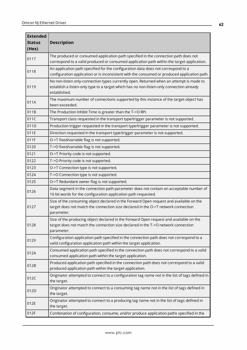
Omron NJ Ethernet Driver
ExtendedStatus(Hex)
Description
0117The produced or consumed application path specified in the connection path does notcorrespond to a valid produced or consumed application path within the target application.
0118An application path specified for the configuration data does not correspond to aconfiguration application or is inconsistent with the consumed or produced application path.
0119No non-listen only-connection types currently open. Returned when an attempt is made toestablish a listen-only type to a target which has no non-listen-only connection alreadyestablished.
011AThe maximum number of connections supported by this instance of the target object hasbeen exceeded.
011B The Production Inhibit Time is greater than the T->O RPI.
011C Transport class requested in the transport type/trigger parameter is not supported.
011D Production trigger requested in the transport type/trigger parameter is not supported.
011E Direction requested in the transport type/trigger parameter is not supported.
011F O->T fixed/variable flag is not supported.
0120 T->O fixed/variable flag is not supported.
0121 O->T Priority code is not supported.
0122 T->O Priority code is not supported.
0123 O->T Connection type is not supported.
0124 T->O Connection type is not supported.
0125 O->T Redundant owner flag is not supported.
0126Data segment in the connection path parameter does not contain an acceptable number of16 bit words for the configuration application path requested.
0127Size of the consuming object declared in the Forward Open request and available on thetarget does not match the connection size declared in the O->T network connectionparameter.
0128Size of the producing object declared in the Forward Open request and available on thetarget does not match the connection size declared in the T->O network connectionparameter.
0129Configuration application path specified in the connection path does not correspond to avalid configuration application path within the target application.
012AConsumed application path specified in the connection path does not correspond to a validconsumed application path within the target application.
012BProduced application path specified in the connection path does not correspond to a validproduced application path within the target application.
012COriginator attempted to connect to a configuration tag name not in the list of tags defined inthe target.
012DOriginator attempted to connect to a consuming tag name not in the list of tags defined inthe target.
012EOriginator attempted to connect to a producing tag name not in the list of tags defined inthe target.
012F Combination of configuration, consume, and/or produce application paths specified in the
www.ptc.com
62

Omron NJ Ethernet Driver
ExtendedStatus(Hex)
Description
connection path are inconsistent with each other.
0130 Information in the data segment is not consistent with the format of the consumed data.
0131 Information in the data segment is not consistent with the format of the produced data.
0132 Null Forward Open request is not supported by target.
0133Connection timeout multiplier (inactivity watchdog) specified is reserved or produces atimeout value too large for the device.
0134 -0202
Reserved by CIP.
0203 Connection timed out.
0204Unconnected request timeout. This may be the result of congestion at the destination nodeor a node not being powered up or present.
0205Connection tick time and connection timeout combination in unconnected request is notsupported by an intermediate node.
0206 Message too large for unconnected_send service.
0207Unconnectedmessage acknowledge was received, but a data response message was notreceived.
0208 -0300
Reserved by CIP.
0301 Insufficient connection buffer memory is available.
0302 Producer along path cannot allocate sufficient bandwidth for the connection on its link.
0303 No consumed connection ID filter available.
0304 Device unable to send scheduled priority data.
0305Connection scheduling information in the originator device is not consistent with theconnection scheduling information on the target network.
0306Connection scheduling information in the originator device cannot be validated on thetarget network.
0307 -0310
Reserved by CIP.
0311 A port specified in a port segment is not available or does not exist.
0312 Link address specified in a port segment is not valid for the target network type.
0313 -0314
Reserved by CIP.
0315 Invalid segment type or segment value in the connection path.
0316The connection path in the Forward Close service does not match the connection path in theconnection being closed.
0317 Scheduled network segment is not present or the value within the segment is invalid.
0318 Link address to self (loopback) is invalid.
0319Secondary system in dual-chassis redundant system is unable to duplicate connectionrequest made to primary system.
031A Request for a module connection has been refused because part of the corresponding data
www.ptc.com
63

Omron NJ Ethernet Driver
ExtendedStatus(Hex)
Description
is already included in a rack connection.
031BRequest for a rack connection has been refused because part of the corresponding data isalready included in a module connection.
031C Miscellaneous connection-related error occurred.
031D Redundant connectionmismatch.
031E The configured number of consumers for a producing application is already reached.
031F No consumers configured for a producing application to use.
0320 - 07FF Vendor-specific error.
0800 Network link in path to module is offline.
0801 -080F
See CIP Safety Specification.
0810 Target application does not have valid data to produce for the requested connection.
0811 Originator application does not have valid data to produce for the requested connection.
0812 Node address has changed since the network was scheduled.
0813A multicast connection has been requested between a producer and a consumer that areon different subnets and the producer is not configured for off-subnet multicast.
0814Information in the data segment indicates that the format of the produced and/orconsumed data is not valid.
0815 - FCFF Reserved by CIP.
0x0C Extended Error CodesThe following error codes are in hexadecimal.
Extended Status (Hex) Description
8010 A download is in progress.
8011 There is an error in tag memory.
For unlisted error codes, refer to the Omron documentation.
0x1F Extended Error CodesThe following error codes are in hexadecimal.
Extended Status (Hex) Description
0101
Could be one of the following errors:
l The combined size of the variable type and read address isincorrect.
l The variable type specification is incorrect.
l The read start address exceeds the range of the variable area.
l The read end address exceeds the range of the variable area.
l There are too many elements.
0102 Could be one of the following errors:
www.ptc.com
64

Omron NJ Ethernet Driver
Extended Status (Hex) Description
l The number of elements does not match the size of the write data.
l The variable type specification is not correct.
l A read only area is included in the write area.
0104 A variable type is out of range.
8001 An internal error occurred.
800D There is an error in the registered tag information.
8014 An internal error occurred.
8016 A variable is not correctly registered.
For unlisted error codes, refer to the Omron documentation.
0x20 Extended Error CodesThe following error code is in hexadecimal.
Extended Status (Hex) Description
8017More than one element was specified for a variable that does not haveelements.
8018Zero elements or data that exceeded the range of the array was specifiedfor an array.
8022The data type specified in the request service data does not agree with thetag information. The AddInfo Length in the request service data is not 0.
8028 Value is out of range.
For unlisted error codes, refer to the Omron documentation.
www.ptc.com
65

Omron NJ Ethernet Driver
Index
-
----------------------------------------------------------------------------------------------------- 57
%
%s | CHANNEL STATISTICS 57
%s | DEVICE STATISTICS 57
0
0x01 Extended Error Codes 61
0x0C Extended Error Codes 64
0x1F Extended Error Codes 64
0x20 Extended Error Codes 65
A
Address Descriptions 28
Address Formats 29
Allow Sub Groups 21
Array 30
Array Block Size 22
Array Element 30
Array Tag Groups 35
Attempts Before Timeout 18
Automatic Tag Database Generation 34
Average Device Turn-Around Time = <number> (milliseconds). 57
Avg. Packets Received/Second = <number> 57
Avg. Packets Sent/Second = <number> 56
Avg. Tag Reads/Second = <number> 57
Avg. Tags/Transaction = <number> 57
www.ptc.com
66
Omron NJ Ethernet Driver
B
Basic 30
Block read request failed due to a framing error. | Block Size = <number> (bytes), Tag Name ='<tag>'. 42
Block read request failed due to a framing error. | Block size = <number> (elements), Starting tagaddress = '<address>'. 42
Blocking Array 24
Boolean 27
Byte 27
C
Channel Assignment 16
Channel Properties 12
Char 27
CIP 22
CIP connection timed-out while uploading project information. 38
CIP Error Codes 59
Coercion 29
Communication Protocol 8
Communications Parameters 21
Communications Routing and Timing 8
Communications Timeouts 18
Condensed 23
CondensedMode 35
Connect Timeout 18
Connection Path Specification 9
Connection Size 22, 24
Create 21
Current value not supported for an XML element on this model. Automatically setting to new value. |Current value = '<value>', XML element = '{<namespace>}<element>', Model = '<model>', Newvalue = '<value>'. 52
D
Data Collection 17
Data Types Description 27
www.ptc.com
67

Omron NJ Ethernet Driver
Database error. Address validation failed for tag. Tag is not added to the database. | Tag name = '<tag>',Tag address = '<address>'. 52
Database error. Array tags renamed because it exceeds max character length. | Array tag name ='<name>', Maximum length = <number>, New array tag name = '<name>'. 55
Database error. CIP connection timed-out while uploading project information. 38
Database error. Data type of complex type is not supported. A tag for this member will not be added tothe database. | Data type = <type>, Complex Type = '<type>', Member = '<name>'. 52
Database error. Encapsulation error occurred during fwd. open request. | Encapsulation error =<code>. 39
Database error. Encapsulation error occurred during register session request. | Encapsulation error =<code>. 38
Database error. Encapsulation error occurred while uploading project information. | Encapsulation error= <code>. 40
Database error. Error occurred during fwd. open request. | CIP error = <code>, Extended error =<code>. 39
Database error. Error occurred while uploading project information. | CIP error = <code>, Extended error= <code>. 38
Database error. Framing error occurred during fwd. open request. 39
Database error. Framing error occurred during register session request. 38
Database error. Framing error occurred while uploading project information. 40
Database error. Internal error occurred. 39
Database error. No more connections available for fwd. open request. 39
Database error. Tag renamed because it exceeds maximum character length. | Tag name = '<tag>',Maximum length = <number>, New tag name = '<tag>'. 54
Database error. Unable to resolve CIP data type for tag. Tag is not added to the database. | Data type =<type>, Tag name = '<tag>'. 52
Database status
Building tag projects, please wait. | Tag project count = <number>. 55Generating OPC tags. 55Retrieving controller project. 55Tags imported. | Data types = <type>, Tags imported = <number>. 55
Delete 21
Demote on Failure 19
Demotion Period 19
Details. | IP = '<address>', Vendor ID = <vendor>, Device type = <type>, Product code = <code>, Revision= <version>, Product name = '<name>', Product SN = <number>. 57
Device Properties 16
Device Properties — Auto-Demotion 19
Device Properties — Tag Generation 19
Device returnedmore data than expected while reading block. Verify the address includes an elementoffset and all dimensions in that offset. | Block Size = <number> (elements), Starting Tag address= '<address>'. 50
Device returnedmore data than expected while reading tag. Verify the address includes an element
www.ptc.com
68

Omron NJ Ethernet Driver
offset and all dimensions in that offset. | Tag address = '<address>'. 50
Discard Requests when Demoted 19
Do Not Scan, Demand Poll Only 17
Double 27
Driver 16
DRIVER STATISTICS 57
DWord 27
E
Elapsed Time = <number> (seconds) 55
Encapsulation Error Codes 59
Encapsulation error occurred during a request. | Encapsulation error = <code>. 54
Encapsulation error occurred while uploading project information. | Encapsulation error = <code>. 37
Error Codes 59
Error occurred during a request to device. | CIP error = <code>, Extended error = <code>. 41
Error occurred while uploading project information. | CIP error = <code>, Extended error = <code>. 37
Errors occurred retrieving controller project. 57
EtherNet-IP 22
Event Log Messages 36
Expanded 23
ExpandedMode 34
F
Float 27
Forward Open requests 8
Frame received from device contains errors. 41
Framing error occurred while uploading project information. 37
G
Generate 20
Global Tags 32
I
ID 16
www.ptc.com
69

Omron NJ Ethernet Driver
Identification 16
Identity requests 8
Inactivity Watchdog 22
Initial Updates from Cache 18
Initialization Transactions = <number> 56
Inter-Request Delay 19
Internal driver error occurred. 58
Internal error occurred while attempting to write tag. Unexpected data type. | Tag address = '<address>',Data type = '<type>', DTRV = <code>. 36
Invalid or corrupt controller project detected while synchronizing. Synchronization will be retriedshortly. 36
Invalid or corrupt controller project detected while synchronizing. Try again later. 58
L
Link Address 9
Long 27
Long Controller Program & Tag Names 34
Lowmemory resources. 36, 58
M
Memory could not be allocated for tag. | Tag address = '<address>'. 54
Model 16
Multi-Hop 9
Multi-Request Packets 24
N
NJ 22
O
On Device Startup 20
On Duplicate Tag 20
On Property Change 20
Optimizing Communications 24
Optimizing the Application 24
www.ptc.com
70

Omron NJ Ethernet Driver
Options 22
Overview 7
Overwrite 21
P
Packets Received = <number> 56
Packets Sent = <number> 56
Parent Group 21
Performance 22, 26
Performance Statistics and Tuning 25
Port ID 9
Predefined Term Tags 32
Project download detected while synchronizing. Synchronization will be retried shortly. 36
Project download detected while synchronizing. Try again later. 58
Project Options 22
R
Read request for tag failed due to a framing error. | Tag address = '<address>'. 42
Read/Write Transactions = <number> 56
Redundancy 23
Remote CPU 9
Request All Data at Scan Rate 17
Request Data No Faster than Scan Rate 17
Request Timeout 18
Requested CIP connection size is not supported by this device. Automatically falling back to maximumsize. | Requested size = <number> (bytes), Maximum size = <number> (bytes). 51
Respect Client-Specified Scan Rate 17
Respect Tag-Specified Scan Rate 18
Routing Examples 9
Routing Path 9
Routing Timing 8
S
ScanMode 17
Setup 8
www.ptc.com
71

Omron NJ Ethernet Driver
Short 27
Simulated 17
Statistics 25
String 27, 30
Strings 24
Structure Tag Addressing 32
Symbol Instance Block Cache Reads = <number> 56
Symbol Instance Block Device Reads = <number> 56
Symbol Instance Non-Block Device Reads = <number> 56
Symbol Instance Non-Block, Array Block Cache Reads = <number> 56
Symbol Instance Non-Block, Array Block Device Reads = <number> 56
Symbolic Device Reads = <number> 55
Symbolic, Array Block Cache Reads = <number> 55
Symbolic, Array Block Device Reads = <number> 55
T
Tag Address Rules 29
Tag Generation 19
Tag Hierarchy 34
Tag Name Rules 29
Tag Scope 32
Tags Read = <number> 56
TCP/IP Port 22
The following errors occurred uploading controller project from device. Resorting to symbolicprotocol. 36
Timeouts to Demote 19
Tuning 26
U
Unable to read block on device. | Block size = <number> (bytes), Tag name = '<tag>', CIP error = <code>,Extended error = <code>. 44
Unable to read block on device. | Block Size = <number> (elements), Starting Tag address = '<address>',CIP error = <code>, Extended error = <code>. 43
Unable to read block on device. Address exceeds current CIP connection size. | Block size = <number>(elements), Starting tag address = '<address>'. 51
Unable to read block on device. Block deactivated. | Block Size = <number> (bytes), Tag Name ='<tag>'. 48
www.ptc.com
72

Omron NJ Ethernet Driver
Unable to read block on device. Block deactivated. | Block Size = <number> (elements), Starting Tagaddress = '<address>', CIP error = <code>, Extended error = <code>. 49
Unable to read block on device. Controller tag data type unknown. Tag deactivated. | Block Size =<number> (elements), Starting tag address = '<address>', Data type = <type>. 44
Unable to read block on device. Data type is illegal for this block. | Block size = <number> (elements),Starting tag address = '<address>', Data type = '<type>'. 46
Unable to read block on device. Data type not supported. Block deactivated. | Block size = <number>(elements), Starting tag address = '<address>', Data type = '<type>'. 45
Unable to read block on device. Internal memory is invalid. Block deactivated. | Block size = <number>(elements), Starting tag address = '<address>'. 49
Unable to read block on device. Internal memory is invalid. Tag deactivated. | Tag address ='<address>'. 49
Unable to read block on device. Native tag size mismatch. | Block size = <number> (bytes), Tag name ='<tag>'. 48
Unable to read block on device. Native tag size mismatch. | Block size = <number> (elements), Startingtag address = '<address>'. 48
Unable to read block. Block deactivated. | Block size = <number> (elements), Starting tag address ='<address>'. 48
Unable to read block. Block does not support multi-element arrays. Block deactivated. | Block size =<number> (elements), Starting tag address = '<address>'. 47
Unable to read tag. | Tag address = '<address>', CIP error = <code>, Extended error = <code>. 43
Unable to read tag. Address exceeds current CIP connection size. | Tag address = '<address>'. 51
Unable to read tag. Controller tag data type unknown. Tag deactivated. | Tag address = '<address>',Data type = <type>. 44
Unable to read tag. Data type is illegal for this tag. | Tag address = '<address>', Data type = '<type>'. 46,49
Unable to read tag. Data type not supported. Tag deactivated. | Tag address = '<address>', Data type ='<type>'. 45
Unable to read tag. Internal memory is invalid. | Tag address = '<address>'. 49
Unable to read tag. Native tag size mismatch. | Tag address = '<address>'. 48
Unable to read tag. Tag deactivated. | Tag address = '<address>'. 48
Unable to read tag. Tag does not support multi-element arrays. Tag deactivated. | Tag address ='<address>'. 47
Unable to retrieve the identity for device. | CIP error = <code>, Extended error = <code>. 53
Unable to retrieve the identity for device. | Encapsulation error = <code>. 53
Unable to retrieve the identity for device. Frame received contains errors. 53
Unable to write to address. Internal memory is invalid. | Tag address = '<address>'. 49
Unable to write to tag. | Tag address = '<address>', CIP error = <code>, Extended error = <code>. 43
Unable to write to tag. | Tag address = '<address>'. 48
Unable to write to tag. Address exceeds current CIP connection size. | Tag address = '<address>'. 51
Unable to write to tag. Controller tag data type unknown. | Tag address = '<address>', Data type =<type>. 44
www.ptc.com
73

Omron NJ Ethernet Driver
Unable to write to tag. Data type is illegal for this tag. | Tag address = '<address>', Data type ='<type>'. 46
Unable to write to tag. Data type not supported. | Tag address = '<address>', Data type = '<type>'. 45
Unable to write to tag. Native tag size mismatch. | Tag address = '<address>'. 47
Unable to write to tag. Tag does not support multi-element arrays. | Tag address = '<address>'. 47
Unknown error occurred. 36, 58
W
Word 27
Write request for tag failed due to a framing error. | Tag address = '<address>'. 41
www.ptc.com
74