
Omron FINS Ethernet Driver for JMobile - esco-da.be UniOP/TechNotes/ptn0366-1.pdf · Tech-note...
12
Tech-note Omron FINS Ethernet Driver for JMobile This Technical Note contains the information needed to connect the HMI to Omron controllers over an Ethernet network using the FINS command set. Exor International S.p.A. Ptn0366
Transcript of Omron FINS Ethernet Driver for JMobile - esco-da.be UniOP/TechNotes/ptn0366-1.pdf · Tech-note...

Tech-note
Omron FINS
Ethernet Driver for JMobile
This Technical Note contains the information needed to connect the HMI to Omron controllers
over an Ethernet network using the FINS command set.
Exor International S.p.A. Ptn0366

Tech-note
ptn0366-1 - 15.09.2014 Omron FINS Ethernet Driver for JMobile
2
Ver. 1.1

Tech-note
ptn0366-1 - 15.09.2014 Omron FINS Ethernet Driver for JMobile
3
Copyright 2014 Exor International S.p.A. – Verona, Italy Subject to change without notice The information contained in this document is provided for informational purposes only. While efforts were made to verify the accuracy of the information contained in this documentation, it is provided “as is” without warranty of any kind. Third-party brands and names are the property of their respective owners.

Tech-note
ptn0366-1 - 15.09.2014 Omron FINS Ethernet Driver for JMobile
4
Contents
Omron FINS Ethernet Driver .......................................................................................................... 5 Settings ............................................................................................................................. 5 Controller Settings ............................................................................................................. 7 Tag Import ......................................................................................................................... 9 Import Files in the Tag Editor ............................................................................................ 9 Aliasing Tag Names in Network Configurations.............................................................. 10 Communication Status .................................................................................................... 11

Tech-note
ptn0366-1 - 15.09.2014 Omron FINS Ethernet Driver for JMobile
5
Omron FINS Ethernet Driver
The chapter describes settings for the driver to be applied in Studio and on the PLC programming software in case anything is required to ensure proper connection between HMI and target device(s).
Document code ptn0366 Version 1.01
Settings
Figure 1
Alias Name to be used to identify nodes in network configurations. The name
will be added as a prefix to each tag name imported for each network node
IP address The Ethernet IP address of the controller connected to the operator panel
Port Defines the port number used in the communication with the PLC. The
Tech-note
ptn0366-1 - 15.09.2014 Omron FINS Ethernet Driver for JMobile
6
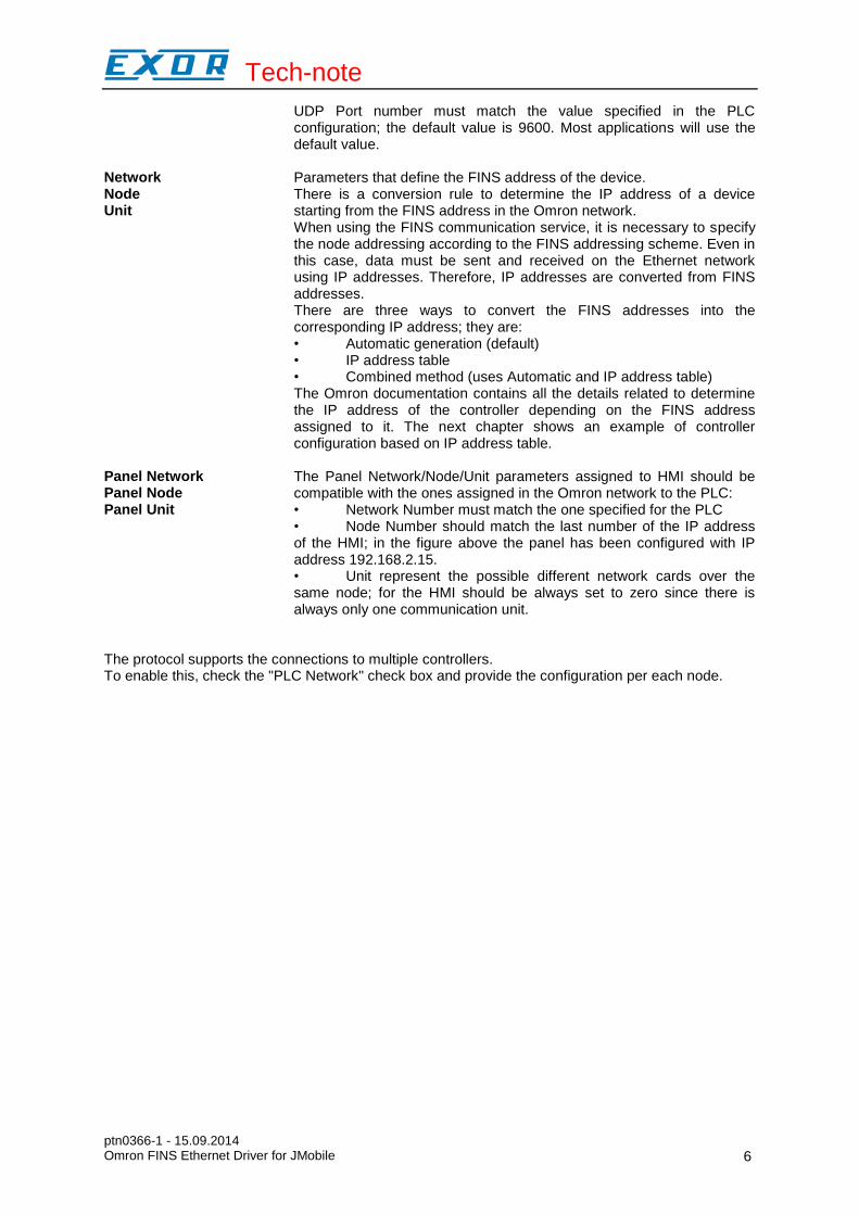
UDP Port number must match the value specified in the PLC configuration; the default value is 9600. Most applications will use the default value.
Network Node Unit
Parameters that define the FINS address of the device. There is a conversion rule to determine the IP address of a device starting from the FINS address in the Omron network. When using the FINS communication service, it is necessary to specify the node addressing according to the FINS addressing scheme. Even in this case, data must be sent and received on the Ethernet network using IP addresses. Therefore, IP addresses are converted from FINS addresses. There are three ways to convert the FINS addresses into the corresponding IP address; they are: • Automatic generation (default) • IP address table • Combined method (uses Automatic and IP address table) The Omron documentation contains all the details related to determine the IP address of the controller depending on the FINS address assigned to it. The next chapter shows an example of controller configuration based on IP address table.
Panel Network Panel Node Panel Unit
The Panel Network/Node/Unit parameters assigned to HMI should be compatible with the ones assigned in the Omron network to the PLC: • Network Number must match the one specified for the PLC • Node Number should match the last number of the IP address of the HMI; in the figure above the panel has been configured with IP address 192.168.2.15. • Unit represent the possible different network cards over the same node; for the HMI should be always set to zero since there is always only one communication unit.
The protocol supports the connections to multiple controllers. To enable this, check the "PLC Network" check box and provide the configuration per each node.

Tech-note
ptn0366-1 - 15.09.2014 Omron FINS Ethernet Driver for JMobile
7
Figure 2
Controller Settings
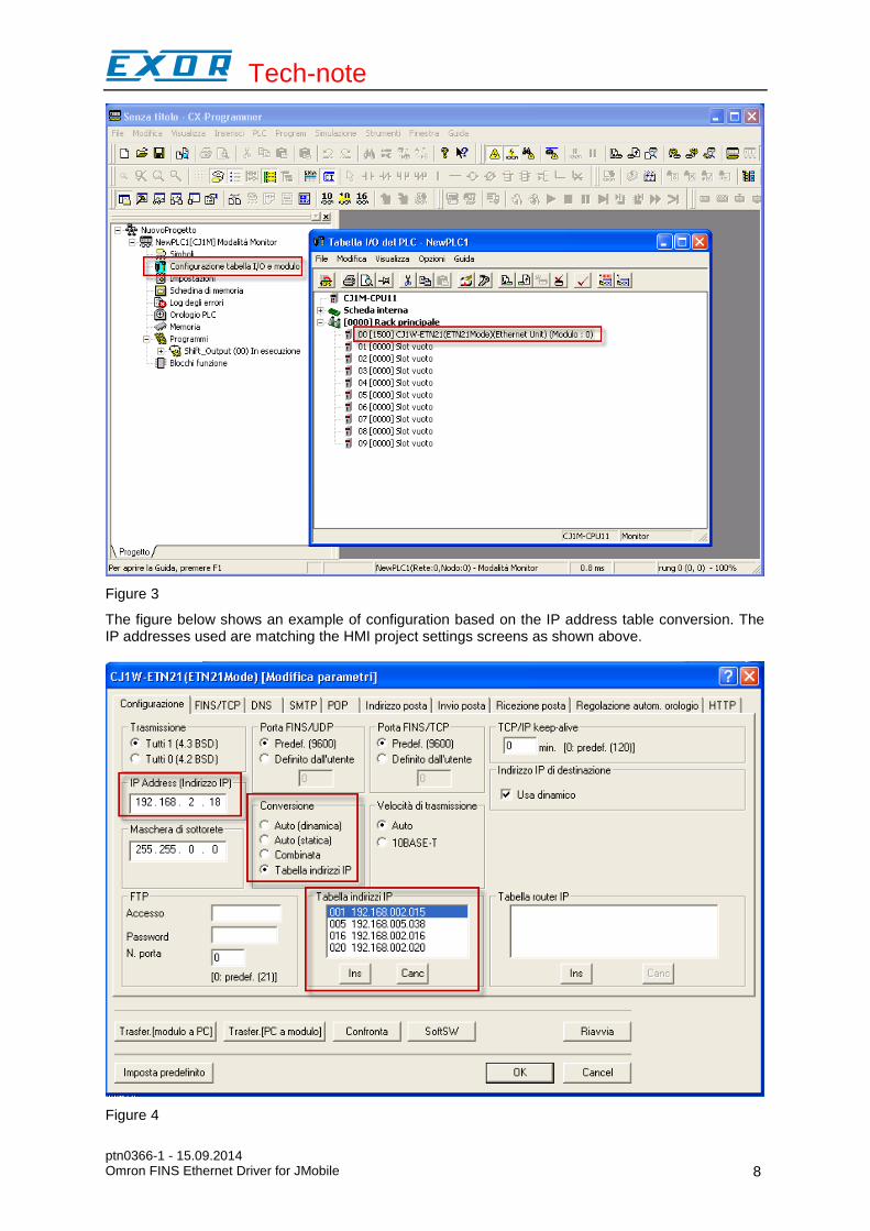
The controller must be properly configured to handle the communication with the panel. The next figure shows the screen of the Omron CX programming software from where you can define the network parameters.
Tech-note
ptn0366-1 - 15.09.2014 Omron FINS Ethernet Driver for JMobile
8
Figure 3
The figure below shows an example of configuration based on the IP address table conversion. The IP addresses used are matching the HMI project settings screens as shown above.
Figure 4

Tech-note
ptn0366-1 - 15.09.2014 Omron FINS Ethernet Driver for JMobile
9
Tag Import
The Omron FINS Ethernet driver can import tag information from CX-Programmer PLC programming software. The tag import filter accepts symbol files with extension “.cxr” created by the Omron programming tool. The “.cxr” files can be exported from the symbol table utility. See in figure how to access the Symbol Table (if configured) from the Omron programming software.
Figure 5
Import Files in the Tag Editor
Select the driver in the Tag Editor and click on the “Import tag” button to start the importer.

Tech-note
ptn0366-1 - 15.09.2014 Omron FINS Ethernet Driver for JMobile
10
Figure 6
Locate the “.cxr” file and confirm. The tags present in the exported document are listed in the tag dictionary from where they can be directly added to the project using the add tags button as shown in the following figure
Figure 7
Aliasing Tag Names in Network Configurations
Tag names must be unique at project level; it often happens that the same tag names are to be used for different controller nodes (for example when the HMI is connected to two devices that are running the same application). Since tags include also the identification of the node and Tag Editor does not support duplicate tag names, the import facility in Tag Editor has an aliasing feature that can automatically add a prefix to imported tags. With this feature tag names can be done unique at project level. The feature works when importing tags for a specific protocol. Each tag name will be prefixed with the string specified by the “Alias”. As shown in the figure below, the connection to a certain controller is assigned the name “Node1”. When tags are imported for this node, all tag names will have the prefix “Node1” making each of them unique at the network/project level.

Tech-note
ptn0366-1 - 15.09.2014 Omron FINS Ethernet Driver for JMobile
11
Figure 8
Note:
Aliasing tag names is only available when tags can be imported. Tags which are added manually in the Tag Editor do not need to have the Alias prefix in the tag name. The Alias string is attached to the tag name only at the moment the tags are imported using Tag Editor. If you modify the Alias string after the tag import has been completed, there will be no effect on the names already present in the dictionary. When the Alias string is changed and tags are imported again, all tags will be imported again with the new prefix string.
Communication Status
The current communication status can be displayed using the dedicated system variables. Please refer to the User Manual for further information about available system variables and their use. The codes supported for this communication driver are:
Error Notes
NAK Returned in case the controller replies with a not acknowledge; can be returned also in case the network/node/unit parameters contained in the PLC response are not matching with panel configuration

Tech-note
ptn0366-1 - 15.09.2014 Omron FINS Ethernet Driver for JMobile
12
Timeout Returned when a request is not replied within the specified timeout period; ensure the controller is connected and properly configured to get network access
Invalid response The panel did receive from the controller a response, but its format or its contents is not as expected; ensure the data programmed in the project are consistent with the controller resources. The same error can be returned also in case the PLC could not complete the processing of the panel request and sent back to the panel and invalid/not completed response.
Cnt error Returned when a specific control character in the protocol frame received does not match with the corresponding one in the request; verify the proper settings of the controller network configuration
General Error Error cannot be identified; should never be reported; contact technical support


![JMobile V2.0 Release Notes - esco-da.be UniOP/TechNotes/ptn0552-0.pdfJMobile V2.0 Release Notes 1 JMobile V2.0 Release Notes ... 8928 [MPOB] Add cable info to ptn0379 Activity 8960](https://static.fdocuments.in/doc/165x107/5adbb6397f8b9add658e4b9a/jmobile-v20-release-notes-esco-dabe-unioptechnotesptn0552-0pdfjmobile-v20.jpg)


![Ethernet Control AC Motor via PLC Using LabVIEWproprietary software, OMRON CX-Programmer over the Ethernet network [3]. With the OMRON FINS Ethernet driver in NI OPC, users can setup](https://static.fdocuments.in/doc/165x107/5e510c2cd46e535fba02fe6f/ethernet-control-ac-motor-via-plc-using-labview-proprietary-software-omron-cx-programmer.jpg)


