Omron E3Z-B Compact Photoelectric Sensor with Built-in ...
18
4 CSM_E3Z_DS_E_18_1 Compact Photoelectric Sensor with Built-in Amplifier E3Z The Standard for Photoelectric Sensors with a Secure Track Record of One Million Sold Yearly. • Long sensing distance of 30 m for Through-beam Models, 4 m for Retro-reflective Models, and 1 m for Diffuse-reflective Models. Mechanical axis and optical axis offset of less than ±2.5° simplifies optical axis adjustment. High stability with unique algorithm that prevents interference of external light. For the most recent information on models that have been certified for safety standards, refer to your OMRON website. Be sure to read Safety Precautions on page 13. Features Industry's Top-level Sensing Distance with Built-in Amplifier A separately sold filter is available to prevent mutual interference for Through-beam Models with red lights sources and a sensing distance of 10 m. Reflective Models include functionality to prevent mutual interference (up to 2 sensors). Long-distance, Through-beam Sensors with a detection distance of 30 m (response time: 2 ms) are also available. Through-beam Retro-reflective with MSR function 30 m 4 m Distance-settable 20 cm Diffuse-reflective 1 m Low-temperature Operation for Applications in Cold-storage Warehouses A wider ambient operating range from −40 to 55°C (main models with connectors). We also provide Sensor I/O Connectors with PUR Cables for high resistance to cold environments. Improved Matching of Optical Axis and Mechanical Axis for Through-beam Models and Retro-reflective Models The offset between the optical axis and the mechanical axis is kept within ±2.5°, so the optical axis can be accurately set simply by mounting the Sensor according to the mechanical axis. Sensor Protection against Incorrect Wiring Through-beam Model receivers and Reflective Models (except the E3Z-LS) The Sensor includes output reverse polarity protection. (A diode to protect against reverse polarity is added to the output line.) Complete Compliance with the EU's RoHS Directive 30 m Optical axis 2.5° max. mechanical axis The receiver will always be in the range of light diffusion. Protection for NPN output models 3 1 12 to 24 VDC Brown Black Blue 100 mA max. Operation indicator (orange) Stability indicator (green) 0 V ZD Load (relay) Photo- electric Sensor main circuit eco Pb Lead, mercury, cadmium hexachrome, polybrominated biphenyl (PBB), and polybrominated diphenyl ether (PBDE) have all been eliminated. Also, burnable polyethylene packaging has been used. 1
Transcript of Omron E3Z-B Compact Photoelectric Sensor with Built-in ...

4
CSM_E3Z_DS_E_18_1
Compact Photoelectric Sensor with Built-in Amplifier
E3Z The Standard for Photoelectric Sensors with a Secure Track Record of One Million Sold Yearly bull Long sensing distance of 30 m for Through-beam Models 4 m for
Retro-reflective Models and 1 m for Diffuse-reflective Models Mechanical axis and optical axis offset of less than plusmn25deg simplifies
optical axis adjustment
High stability with unique algorithm that prevents interference of external light
For the most recent information on models that have been certified for safety standards refer to your OMRON website
Be sure to read Safety Precautions on page 13
Features
Industrys Top-level Sensing Distance with Built-in Amplifier A separately sold filter is available to prevent mutual interference for Through-beam Models with red lights sources and a sensing distance of 10 m Reflective Models include functionality to prevent mutual interference (up to 2 sensors)
Long-distance Through-beam Sensors with a detection distance of 30 m (response time 2 ms) are also available
Through-beam
Retro-reflective with MSR function
30 m
4 m Distance-settable
20 cm Diffuse-reflective
1 m Low-temperature Operation for Applications in Cold-storage Warehouses A wider ambient operating range from minus40 to 55degC (main models with connectors) We also provide Sensor IO Connectors with PUR Cables for high resistance to cold environments
Improved Matching of Optical Axis and Mechanical Axis for Through-beam Models and Retro-reflective Models The offset between the optical axis and the mechanical axis is kept within plusmn25deg so the optical axis can be accurately set simply by mounting the Sensor according to the mechanical axis
Sensor Protection against Incorrect Wiring Through-beam Model receivers and Reflective Models (except the E3Z-LS)
The Sensor includes output reverse polarity protection (A diode to protect against reverse polarity is added to the output line)
Complete Compliance with the EUs RoHS Directive
30 m
Optical axis
25deg maxmechanical axis
The receiver will always be in the range of light diffusion
Protection for NPN output models
3
1 12 to 24 VDCBrown
Black
Blue
100 mA max
Operation indicator (orange)
Stability indicator (green)
0 V
ZD
Load (relay)
Photo-electric Sensor main circuit
eco Pb
Lead mercury cadmium hexachrome polybrominated biphenyl (PBB) and polybrominated diphenyl ether (PBDE) have all been eliminated Also burnable polyethylene packaging has been used
1
E3Z Ordering Information
Sensors [Refer to Dimensions on page 14] Red light Infrared light
Sensing method Appearance Connection method Sensing distance Model
NPN output PNP output
Through-beam (Emitter + Receiver) 3
Pre-wired (2 m) E3Z-T61 2M 4 5 E3Z-T81 2M 4 5 Emitter E3Z-T61-L 2M Receiver E3Z-T61-D 2M
Emitter E3Z-T81-L 2M Receiver E3Z-T81-D 2M
Standard M8 connector E3Z-T66 E3Z-T86 Emitter E3Z-T66-L Receiver E3Z-T66-D
Emitter E3Z-T86-L Receiver E3Z-T86-D
Pre-wired (2 m) E3Z-T61A 2M 4 E3Z-T81A 2M 4 Emitter E3Z-T61-A-L 2M Receiver E3Z-T61-A-D 2M
Emitter E3Z-T81-A-L 2M Receiver E3Z-T81-A-D 2M
Standard M8 connector E3Z-T66A E3Z-T86A Emitter E3Z-T66-A-L Receiver E3Z-T66-A-D
Emitter E3Z-T86-A-L Receiver E3Z-T86-A-D
Pre-wired (2 m) E3Z-T62 2M 4 E3Z-T82 2M Emitter E3Z-T62-L 2M Receiver E3Z-T62-D 2M
Emitter E3Z-T82-L 2M Receiver E3Z-T82-D 2M
Standard M8 connector E3Z-T67 E3Z-T87 Emitter E3Z-T67-L Receiver E3Z-T67-D
Emitter E3Z-T87-L Receiver E3Z-T87-D
Retro-reflective with MSR function 1
Pre-wired (2 m) E3Z-R61 2M 4 5 E3Z-R81 2M 4 5
Standard M8 connector E3Z-R66 E3Z-R86
Diffuse-reflective
Pre-wired (2 m) E3Z-D61 2M 4 E3Z-D81 2M 4 5
Standard M8 connector E3Z-D66 E3Z-D86
Pre-wired (2 m) E3Z-D62 2M 4 5 E3Z-D82 2M 4 5
Standard M8 connector E3Z-D67 E3Z-D87
Pre-wired (2 m) E3Z-L61 2M 4 5 E3Z-L81 2M 4 5
Standard M8 connector E3Z-L66 E3Z-L86
Distance-settable Refer to E3Z-LS
Pre-wired (2 m) E3Z-LS61 2M 4 E3Z-LS81 2M 4
Standard M8 Connector E3Z-LS66 E3Z-LS86
Pre-wired (2 m) E3Z-LS63 2M E3Z-LS83 2M 5
Standard M8 connector E3Z-LS68 E3Z-LS88
Slit-type Through-beam Refer to E3Z-G
1 axis Pre-wired (2 m)
E3Z-G61 2M 4 5 E3Z-G81 2M 4 5
2 axes E3Z-G62 2M 4 E3Z-G82 2M 4
1 axis Pre-wired M8 connector
E3Z-G61-M3J E3Z-G81-M3J
2 axes E3Z-G62-M3J E3Z-G82-M3J
Limited-reflective for transparent glasses
Pre-wired (2 m) E3Z-L63 2M E3Z-L83 2M
Standard M8 connector E3Z-L68 E3Z-L88
Retro-reflective with-out MSR function for clear plastic bottles
Pre-wired (2 m) 2 E3Z-B61 2M E3Z-B81 2M 4
Standard M8 connector E3Z-B66 E3Z-B86
Pre-wired (2 m) 2 E3Z-B62 2M 4 E3Z-B82 2M 4
Standard M8 connector E3Z-B67 E3Z-B87
15 m
10 m
30m
4 m (100 mm)
2
5 to 100 mm (wide view)
1 m
90plusmn30 mm (narrow beam)
20 to 40 mm (BGS min setting) 20 to 200 mm (BGS max setting)
40 min Incident threshold (FGS min setting)
200 min Incident threshold (FGS max setting)
2 to 20 mm (BGS min setting) 2 to 80 mm (BGS max setting)
25 mm
30plusmn20 mm
1
500 mm (80 mm)
2 m (500 mm)
1 The Reflector is sold separately Select the Reflector model most suited to the application 2 The sensing distance specified is possible when the E39-R1S is used Values in parentheses indicate the minimum required distance between the Sensor and Reflector 3 Through-beam Sensors are normally sold in sets that include both the Emitter and Receiver 4 M12 Standard Pre-wired Connector Models are also availavble
When ordering add -M1J 03M to the end of the model number (eg E3Z-T61-M1J 03M) The cable is 03 m long
5 M12 Pre-wired Smartclick Connector Models are also availavble When ordering add -M1TJ 03M to the end of the model number (eg E3Z-T61-M1TJ 03M) The cable is 03 m long
2
E3Z
Red light Infrared light Oil-resistive Sensors [Refer to Dimensions on page 14]
Sensing method Appearance Connection method Sensing distance Model
NPN output PNP output
Through-beam (Emitter + Receiver) 3
Pre-wired (2 m) E3Z-T61K 2M 4 E3Z-T81K 2M 4 Emitter E3Z-T61K-L 2M Receiver E3Z-T61K-D 2M
Emitter E3Z-T81K-L 2M Receiver E3Z-T81K-D 2M
Pre-wired M8 connector E3Z-T61K-M3J 03M E3Z-T81K-M3J 03M Emitter E3Z-T61K-L-M3J 2M Receiver E3Z-T61K-D-M3J 2M
Emitter E3Z-T81K-L-M3J 2M Receiver E3Z-T81K-D-M3J 2M
Retro-reflective with MSR function 1
Pre-wired (2 m) 2 E3Z-R61K 2M 4 E3Z-R81K 2M
Pre-wired M8 connector E3Z-R61K-M3J 03M E3Z-R81K-M3J 03M
Diffuse-reflective
Pre-wired (2 m) E3Z-D61K 2M 4 E3Z-D81K 2M
Pre-wired M8 connector E3Z-D61K-M3J 03M E3Z-D81K-M3J 03M
Pre-wired (2 m) E3Z-D62K 2M 4 E3Z-D82K 2M
Pre-wired M8 connector E3Z-D62K-M3J 03M E3Z-D82K-M3J 03M
15 m
3 m (150 mm)
5 to 100 mm (wide view)
1 m
1 The Reflector is sold separately Select the Reflector model most suited to the application 2 The sensing distance specified is possible when the E39-R1S is used Values in parentheses indicate the minimum required distance between the Sensor and Reflector 3 Through-beam Sensors are normally sold in sets that include both the Emitter and Receiver 4 M12 Standard Pre-wired Connector Models are also availavble
When ordering add -M1J 03M to the end of the model number (eg E3Z-T61-M1J 03M) The cable is 03 m long
Accessories (Order Separately) Slit (A Slit is not provided with Through-beam Sensors) Order a Slit separately if required [Refer to Dimensions on page 16]
Slit width Sensing distance Minimum detectable object
(Reference value) Model Contents E3Z-T E3Z-TA
05-mm dia 50 mm 35 mm 02-mm dia E39-S65A
One set (contains Slits for
both the Emitter and Receiver)
1-mm dia 200 mm 150 mm 04-mm dia E39-S65B 2-mm dia 800 mm 550 mm 07-mm dia E39-S65C
05 times 10 mm 1 m 700 mm 02-mm dia E39-S65D 1 times 10 mm 22 m 15 m 05-mm dia E39-S65E 2 times 10 mm 5 m 35 m 08-mm dia E39-S65F
Reflectors (Reflector required for Retroreflective Sensors) A Reflector is not provided with the Sensor Be sure to order a Reflector separately [Refer to Dimensions on E39-LE39-SE39-R]
Name
Sensing distance
Model Quantity Remarks E3Z-R E3Z-RK E3Z-B1-B6 E3Z-B2-B7
Rated value (sensing
distance of 15 m)
Reference value (sensing
distance of 10 m) Rated value Rated value Rated value
Reflector
3 m (100 mm) --- 2 m (100 mm) --- --- E39-R1 1
bull Retro-reflective models are not provided with Reflectors
bull The MSR function is enabled
4 m (100 mm) --- 3 m (150 mm) 500 mm (80 mm) 2 m (500 mm) E39-R1S 1 --- 5 m (100 mm) --- --- --- E39-R2 1 --- 25 m (100 mm) --- --- --- E39-R9 1 --- 35 m(100 mm) --- --- --- E39-R10 1
Fog Preventive Coating
--- 3 m (100 mm) --- 500 mm (80 mm) 2 m (500 mm) E39-R1K 1
Small Reflector --- 15 m (50 mm) --- --- --- E39-R3 1
Tape Reflector --- 700 mm (150 mm) --- --- --- E39-RS1 1 --- 11 m (150 mm) --- --- --- E39-RS2 1 --- 14 m (150 mm) --- --- --- E39-RS3 1
Note 1 If you use the Reflector at any distance other than the rated distance make sure that the stability indicator lights properly when you install the Sensor 2 Refer to Reflectors on E39-LE39-SE39-R for details
Values in parentheses indicates the minimum required distance between the Sensor and Reflector
Mutual Interference Protection Filter A Filter is not provided with the Sensor (for the through-beam E3Z-TA) Order a Filter separately if required Sensing distance AppearanceDimensions Model Quantity Remarks
3 m
108 49
74 1
314 112
02
E39-E11 Two sets each for the Emitter and Receiver (total of four pieces)
Can be used with the E3Z-TA Through-beam models The arrow indicates the direc-tion of polarized light Mutual interference can be prevented by altering the direction of polarized light from or to adjacent Emitters and Receivers
Note The polarization directions of the Filters are offset by 90ordm to prevent interference When you install the Emitter and Receiver install them at the same angle to maintain this offset
3
E3Z
Mounting Brackets A Mounting Bracket is not enclosed with the Sensor Order a Mounting Bracket separately if required [Refer to Dimensions on E39-LE39-SE39-R]
Appearance Model (material) Quantity Remarks Appearance Model (material) Quantity Remarks
E39-L153 (SUS304) 1
1 E39-L98 (SUS304) 2
1 Metal Protective Cover Bracket
Mounting Brackets
E39-L104 (SUS304) 1
1 E39-L150 (SUS304)
1
(Sensor adjuster)
Easily mounted to the
E39-L43 (SUS304) 2
1 Horizontal Mounting Brackets
aluminum frame rails of conveyors and easily adjusted
E39-L151 (SUS304)
1 For left to right adjust-ment
E39-L142 (SUS304) 2
1 Horizontal Protective Cover Bracket
E39-L44 (SUS304)
1 Rear Mounting Bracket E39-L144 (SUS304) 2
1 Compact Protective Cover Bracket (For E3Z only)
Note 1 When using Through-beam models order one bracket for the Receiver and one for the Emitter 2 Refer to Mounting Brackets on E39-LE39-SE39-R for details
1 Cannot be used for Standard Connector models with mounting surface on the bottom In that case use Pre-wired Connector models 2 Cannot be used for Standard Connector models
Sensor IO Connectors (Sockets on One Cable End) (Models for Connectors and Pre-wired Connectors A Connector is not provided with the Sensor Be sure to order a Connector separately) [Refer to Dimensions for XS3]
Size Cable Appearance Cable type Model
M8 1 Standard
Straight 3 2 m
4-wire
XS3F-M421-402-A
5 m XS3F-M421-405-A
L-shaped 3 4 2 m XS3F-M422-402-A
5 m XS3F-M422-405-A
M8 PUR (Polyure-thane) cable 2
Straight 3 2 m
4-wire
XS3F-M421-402-L
5 m XS3F-M421-405-L
L-shaped 3 4 2 m XS3F-M422-402-L
5 m XS3F-M422-405-L
Note When using Through-beam models order one connector for the Receiver and one for the Emitter 1 Refer to Introduction to Sensor IO ConnectorsSensor Controllers for details 2 The Sensor can be used in low-temperature environments (minus25degC to minus40degC) Do not use the Sensor in locations that are subject to oil 3 The connector will not rotate after connecting 4 The cable is fixed at an angle of 180deg from the sensor emitterreceiver surface
4
E3Z Ratings and Specifications
Sensing method Through-beam Retro-reflective with MSR function
(Narrow-Diffuse-reflective beam Models)
Model
Item
NPN out-put
Pre-wired E3Z-T61 E3Z-T62 E3Z-T61A E3Z-R61 E3Z-D61 E3Z-D62 E3Z-L61
Connector (M8) E3Z-T66 E3Z-T67 E3Z-T66A E3Z-R66 E3Z-D66 E3Z-D67 E3Z-L66
PNP out-put
Pre-wired E3Z-T81 E3Z-T82 E3Z-T81A E3Z-R81 E3Z-D81 E3Z-D82 E3Z-L81
Connector (M8) E3Z-T86 E3Z-T87 E3Z-T86A E3Z-R86 E3Z-D86 E3Z-D87 E3Z-L86
Sensing distance 15 m 30 m 10 m
4 m (100 mm) 1 (when using E39-R1S) 3 m (100 mm) 1 (when using E39-R1)
100 mm (white paper 100 times 100 mm)
1 m (white paper 300 times 300 mm)
90 + 30 mm (white paper 100 x 100 mm)
Spot diameter (reference value) ---
(25 dia and sensing dis-tance of 90 mm)
Standard sensing object Opaque 12-mm dia min Opaque 75-mm dia min ---
Minimum detectable object (reference value) ---
01 mm (cop-per wire)
Differential travel --- 20 max of setting distance Refer to Engi-neering data on page 8
Directional angle Both emitter and receiver 3 to 15deg 2 to 10deg ---
Light source (wavelength) Infrared LED (870 nm) Red LED (660 nm) Red LED (660 nm) Infrared LED (860 nm) Red LED
(650 nm)
Current consumption 35 mA max (Emitter 15 mA max Receiv-er 20 mA max) 30 mA max
Protection circuits Reversed power supply polarity protection Output short-circuit protection and Re-versed output polarity protection
Reversed power supply polarity protection Output short-circuit protection Mutual interference prevention and Reversed output polarity protection
Response time Operate or reset 1 ms max
Operate or reset 2 ms max
Operate or reset 1 ms max
Degree of protection IEC IP67
Connection method Pre-wired cable (standard length 2 m and 05 m) Connector (M8)
Weight (packedstate)
Pre-wired cable (2 m) Approx 120 g Approx 65 g
Connector Approx 30 g Approx 20 g
Material Case PBT (polybutylene terephthalate)
Lens Modified polyarylate Methacrylic resin Modified polyarylate
Sensing method Retro-reflective for clear plastic bottles (without MSR function)
Model NPN output E3Z-B61 E3Z-B66 E3Z-B62 E3Z-B67
Item PNP output E3Z-B81 E3Z-B86 E3Z-B82 E3Z-B87
Sensing distance 500 mm (80 mm) 1 (using E39-R1S) 2 m (500 mm) 1 2 (using E39-R1S)
Standard sensing object 500-ml (65-mm dia) transparent round plastic bottles
Light source (wavelength) Red LED (660 nm)
Current consumption 30 mA max
Protection circuits Reversed power supply polarity protection Output short-circuit protection Mutual interference prevention and Reversed output polarity protection
Response time Operate or reset 1 ms max
Degree of protection IEC IP67
Connection method Pre-wired cable (standard length 2 m and 05 m) Connector (M8 4 pins) Pre-wired cable (standard
length 2 m and 05 m) Connector (M8 4 pins)
Weight (packed state)
Pre-wired cable (2 m) Approx 65 g
Standard Connector Approx 20 g
Material Case PBT (polybutylene terephthalate)
Lens Modified polyarylate
1 Values in parentheses indicate the minimum required distances between the Sensors and Reflectors 2 Plastic bottles must pass with the minimum clearance of 500 mm
5
E3Z
Sensing method
Model NPN output
Item PNP output
Sensing distance
Spot diameter (reference value)
Minimum detectable object (reference value)
Light source (wavelength)
Current consumption
Protection circuits
Response time
Degree of protection
Connection method
Weight Pre-wired cable (2 m) (packed state) Standard Connector
Case Material
Lens
Transparent glass Limited-reflective (for transparent object detection )
E3Z-L63 E3Z-L68
E3Z-L83 E3Z-L88
30plusmn20 mm (transparent glasses 100 times 100 mm)
2-mm dia min (at sensing distance of 30 mm)
01 mm dia (copper wire)
Red LED (660 nm)
30 mA max
Power supply reverse polarity protection Output short-circuit protection Mutual interference prevention Reverse output polarity protection
Operate or reset 1 ms max
IEC IP67
Pre-wired (standard length 2 m) M8 connector
Approx 65 g
Approx 20 g
PBT (polybutylene terephthalate)
Modified polyarylate
6
E3Z
Oil-resistant
Sensing method Through-beam Retro-reflective Diffuse-reflective
Model
NPN out-put
Pre-wired Models E3Z-T61K E3Z-R61K E3Z-D61K E3Z-D62K
M8 Pre-wired connector E3Z-T61K-M3J E3Z-R61K-M3J E3Z-D61K-M3J E3Z-D62K-M3J
PNP out-put
Pre-wired Models E3Z-T81K E3Z-R81K E3Z-D81K E3Z-D82K
Item M8 Pre-wired connector E3Z-T81K-M3J E3Z-R81K-M3J E3Z-D81K-M3J E3Z-D82K-M3J
Sensing distance 15 m
3 m (150 mm) (when using E39-R1S) 2 m (100 mm) (when using E39-R1)
100 mm (white paper 100 times 100 mm)
1 m (white paper 300 times 300 mm)
Standard sensing object Opaque 12-mm dia min Opaque 75-mm dia min ---
Differential travel --- 20 max of setting distance
Directional angle Both emitter and receiver 3 to 15deg 2 to 10deg ---
Light source (wavelength) Infrared LED (870 nm) Red LED (660 nm) Infrared LED (860 nm)
Current consumption 35 mA max (Emitter 15 mA max Receiver 20 mA max)
30 mA max
Protection circuits
Reversed power supply polarity protection Output short-circuit protection and Reversed output po-larity protection
Reversed power supply polarity protection Output short-circuit protection Mutual in-terference prevention and Reversed output polarity protection
Response time Operate or reset 1 ms max
Degree of protection IP67 (IEC) Oil resistant models IP67 (IEC) (in-house standards oilproof) excluding cables and connectors
Connection method Pre-wired cable (standard length 2 m) M8 Pre-wired Connector
Weight (packed state)
Pre-wired cable (2 m) Approx 120 g Approx 65 g
Connector (M8 4 pins) Approx 50 g Approx 30 g
Material Case PBT (polybutylene terephthalate)
Lens Modified polyarylate Methacrylic resin Modified polyarylate
Values in parentheses indicate the minimum required distance between the Sensor and Reflector
Common Power supply voltage 12 to 24 VDCplusmn10 ripple (p-p) 10 max
Control output
Load power supply voltage 264 VDC max Load current 100 mA max Residual voltage Load current of less than 10 mA 1 V max
Load current of 10 to 100 mA 2 V max Open collector output (NPNPNP depending on model) Light-ONDark-ON selectable
Sensitivity adjustment One-turn adjuster
Ambient illumination (Receiver side) Incandescent lamp 3000 lx max Sunlight 10000 lx max
Ambient temperature range Operating minus25 to 55degC Some connector models minus40degC to 55degC (with no icing or condensation) Storage minus40 to 70degC (with no icing or condensation)
Ambient humidity range Operating 35 to 85 Storage 35 to 95 (with no condensation)
Insulation resistance 20 MΩ min at 500 VDC
Dielectric strength 1000 VAC 5060 Hz for 1 min
Vibration resistance Destruction 10 to 55 Hz 15 mm double amplitude for 2 hours each in X Y and Z directions
Shock resistance Destruction 500 ms2 3 times each in X Y and Z directions
Indicator Operation indicator (orange) Stability indicator (green) Through-beam Emitter has power indicator (orange) only
Accessories Instruction manual (Neither Reflectors nor Mounting Brackets are provided with any of the above models)
The ambient temperature range during operation for connector models depends on the model For the E3Z-T66T86R66R86 the range is minus40degC to 55degC For the E3Z-D66D86D67D87 the range is minus30degC to 55degC For other connector models the range is minus25degC to minus55degC The sensing distance for Retro-reflective Models (E3Z-R66R86) between minus40degC to minus25degC however will be as follows (not the values in the table) With E39-R1S 3 m (100 mm) With E39-R1 2 m (100 mm) Also use the XS3F-M42-4-L Sensor IO Connector (PUR cable) for applications between minus25degC to minus40degC (Refer to page 4)
7
E3Z Engineering Data (Reference Value)
Parallel Operating Range
Through-beam Models Through-beam Models Through-beam Models
E3Z-T1(T6) E3Z-TA E3Z-T2(T7)
1000
800
600
400
200
0
minus200
minus400
minus600
minus800
minus1000
40302010 Distance
X (m)
Y
X
Dis
tanc
e Y
(m
m)
Dis
tanc
e Y
(m
m)
40302010
Y
X
Distance X (m)
05200
Dis
tanc
e Y
(m
m)
10 20 30 40 Distance
X (m)
1000 20
800 15
600 10
400
00
minus200 minus05
minus400 minus10
minus600
minus15minus800
minus1000 minus20
Through-beam Models Through-beam Models Retro-reflective Models
E3Z-T1(T6) and Slit E3Z-TA and Slit E3Z-R1(R6) and Reflector (A Slit is mounted to the Emitter and (A Slit is mounted to the Emitter and Receiver) Receiver)
Y
X
8642
E39-R9
E39-R1SE39-R1
E39-R10
E39-R2
E39-R1K
E39-R3
Dis
tanc
e Y
(m
m)
Distance X (m)
200
54321
E39-S65B
E39-S65C
E39-S65D E39-S65E
E39-S65F
Distance X (m)
Y
X
200
150
100
Y
X
250
200
150
100
50
0
minus50
minus100
minus150
minus200
minus250
54321
E39-S65B
E39-S65C
E39-S65D
E39-S65E E39-S65F
Distance X (m)
Dis
tanc
e Y
(m
m)
Dis
tanc
e Y
(m
m)
150
100
5050
00
minus50 minus50
minus100 minus100
minus150minus150
minus200 minus200
E3Z-B1B6 + E39-R1S Reflector E3Z-B2B7 + E39-R1S (Order Separately) Reflector (Order Separately)
305 1 15 2 25
Y
X
minus50
minus40
minus30
minus20
minus10
0
10
20
30
40
50
Dis
tanc
e Y
(m
m)
Reflector E39-R1S
500-mm type
Distance X (m)
Dis
tanc
e Y
(m
m) 100
80
60
40
20
0
minus20
minus40
minus60
minus80
minus100
45 05 1 15 2 25 3 35 4
Reflector E39-R1S
Distance X (m)
2-m type
Y
X
8
E3Z
Operating Range
Diffuse-reflective Models Diffuse-reflective Models Narrow-beam Reflective Models
E3Z-D1(D6) E3Z-D2(D7) E3Z-L1(L6)
Dis
tanc
e Y
(m
m) 10
250150 20010050
Y
X
Sensing object 100 times 100 mm white paper
Distance X (m)
minus4 minus40
minus6minus20 minus60
minus8
minus30 minus80 minus10
20
1610 1206 140802 04
Y
X
Sensing object 300 times 300 mm white paper
Distance X (m)
2
Dis
tanc
e Y
(m
m)30 80
Y
X
Sensing object 100 times 100 mm white paper
50 100 150 200
250 Distance X (m)
Dis
tanc
e Y
(m
m)
860 20
6 40
410
0 0 0
minus2minus20minus10
Exc
ess
gain
rat
io
Excess Gain vs Set Distance
Through-beam Models Retro-reflective Models Diffuse-reflective Models
E3Z-T1(T6)-TA-T2(T7) E3Z-R1(R6) and Reflector E3Z-D1(D6)
100
E3Z-TA
E3Z-T2 (T7)
E3Z-T1 (T6)
Sensing object 100 times 100 mm white paper100 100
Exc
ess
gain
rat
io
Exc
ess
gain
rat
io
E39-R9
E39-R1K
E39-R10
E39-R1S
E39-R2
E39-R3
E39-R1
70 50
30
10 1010 7 5
3
Operating 1 11 level 07
05
03
01 01 0 10 20 30 40 50 60 70 80 0 2 4 6 8 10 0 50 100 150 200 250 300 350
Distance (m) Distance (m) Distance (m)
01
Diffuse-reflective Models Narrow-beam Reflective Models Limited reflective Models
E3Z-D2(D7) E3Z-L1(L6) E3Z-L3(L8)
Sensing object 300 times 300 mm white paper
0 05 1 15 2 25 3
Exc
ess
gain
rat
io 100 70 50
30
10 Exc
ess
gain
rat
io
Exc
ess
gain
rat
io
0 50 100 150 200 250 300 350
White paper
SUS
Glass
100 100 70 50
30
10
70 50
30
10 7 7 7 5 5 5
3 3 3
Operating Operating Operating 1 1 1 level levellevel 07 07 07
05 05 05
03 03 03
01 01 01 0 20 40 60 80 100 120
Distance (m) Distance (m) Distance (m)
9
100
E3Z
Excess Gain vs Set Distance
E3Z-B1B6 + E39-R1S E3Z-B2B7 + E39-R1S Reflector (Order Separately) Reflector (Order Separately)
100
Narrow-beam Reflective Models Narrow-beam Reflective Models
E3Z-L1(L6) E3Z-L1(L6)
Spot Diameter vs Sensing Distance Differential Travel vs Sensing Distance
Diffuse-reflective Models Diffuse-reflective Models Narrow-beam Reflective Models
E3Z-D1(D6) E3Z-D2(D7) E3Z-L1(L6)
Sensing Object Size vs Sensing Distance
atio
Exc
ess
gain
rD
ista
nce
(m)
atio
Exc
ess
gain
r
500-mm type
05 1 15 2 25 3
2-m type
05 1 15 2 25 3 35 4 45 5 Distance (m)
1010
11
01 01
Distance (m)
Dis
tanc
e (m
m)
d
d
350
300
250
200
150
100
50 Black paper
SUS (glossy surface)
White paper
0 50 100 150 200 250 300 350
Side length (one side) of sensing object d (mm)
d
d
45
4
35
3
25
2
15
1
05 Black paper
SUS (glossy surface)
White paper
0 50 100 150 200 250 300 350 Side length (one side) of sensing object d (mm)
d
d
Dis
tanc
e (m
)
White paper
300
250
200
150
100
50
0 1 2 3 5 75 10 20 30 100
Side length (one side) of sensing object d (mm)
Spo
t dia
met
er (
mm
) 40
35
30
25
20
15
10
05
Diff
eren
tial t
rave
l (m
m)
0 20 40 60 80 100 120 140 160
Distance (mm)
30
15
10
5
0 50 75 100 125 150
Distance (mm)
25
20
10
E3Z IO Circuit Diagrams
NPN Output
Model Operation mode Timing charts Operation
selector Output circuit
E3Z-T61(K) E3Z-T66 E3Z-T62 E3Z-T67 E3Z-T61A E3Z-T66A E3Z-R61(K) E3Z-R66 E3Z-D61(K) E3Z-D66 E3Z-D62(K) E3Z-D67 E3Z-L61 E3Z-L66 E3Z-B61 E3Z-B66 E3Z-B62 E3Z-B67 E3Z-L63 E3Z-L68
Light-ON
Incident light
No incident light Operation ON indicator OFF(orange) Output ON transistor OFF
Load Operate (eg relay) Reset
(Between brown (1) and black (4) leads)
L side (LIGHT ON)
Through-beam Receivers Retro-reflective Models Diffuse-reflective Models Limited reflective Models
Br o wn 12 to 24 VDC Ope r ation 1
indicator Stability indicator 100 mA Load
(O r ange ) (Green) (Control max (Rel a y ) output) Bla c k
Photo - 4 elect r ic Sensor ZDmain Bluecircuit 3
0 V
Connector Pin Arrangement
2 4 1 3
Pin 2 is not used
Dark-ON
Incident light
No incident light Operation ON indicator
OFF(orange) Output ON transistor OFF
Load Operate (eg relay) Reset
(Between brown (1) and black (4) leads)
D side (DARK ON)
Through-beam Emitter Power indicator (orange)
Photo-electric Sensor main circuit
Brown 1
Connector Pin Arrangement
2 4 12 to 1 3 24 VDC
Pins 2 and 4 are not used3
Blue
PNP Output
Model Operation mode Timing charts Operation
selector Output circuit
E3Z-T81(K) E3Z-T86 E3Z-T82 E3Z-T87 E3Z-T81A E3Z-T86A E3Z-R81(K) E3Z-R86 E3Z-D81(K) E3Z-D86 E3Z-D82(K) E3Z-D87 E3Z-L81 E3Z-L86 E3Z-B81 E3Z-B86
Light-ON
Incident light
No incident light Operation ON indicator OFF(orange) Output ON transistor OFF
Load Operate (eg relay) Reset
(Between blue (3) and black (4) leads)
L side (LIGHT ON)
Through-beam Receivers Retro-reflective Models Diffuse-reflective Models Limited reflective Models
Brown 12 to 24 VDC Operation 1 indicator Stability
indicator ZD
(Orange) (Green) Black Photo- 4
electric (ControlSensor 100 mA Load main output) (Relay) circuit Bluemax
3 0 V
Connector Pin Arrangement
2 4 1 3
Pin 2 is not used
Dark-ON
Incident light
No incident light Operation ON indicator OFF(orange) Output ON transistor OFF
Load Operate (eg relay) Reset
(Between blue (3) and black (4) leads)
D side (DARK ON)
Through-beam Emitter Brown 1
Power
E3Z-B82 indicator Connector Pin Arrangement(orange) E3Z-B87 Photo-
E3Z-L83 E3Z-L88
electric 2 4 Sensor 12 to 24 VDC 1 3 Main Circuit
Blue 3 Pins 2 and 4 are not used
Models numbers for Through-beam Sensors (E3Z-T) are for sets that include both the Emitter and Receiver The model number of the Emitter is expressed by adding -L to the set model number (example E3Z-T61-L 2M) the model number of the Receiver by adding -D (example E3Z-T61-D 2M) Refer to Ordering Information to confirm model numbers for Emitter and Receivers
11
E3Z
Plugs (Sensor IO Connectors)
M8 connector Pin arrangement Wire color
24
13
1 2 3 4
Brown White Blue Black
XS3F-M421-402-A XS3F-M421-405-A XS3F-M422-402-A Note Pin 2 is not used XS3F-M422-405-A
Nomenclature
Classifi-cation
Wire color
Connector pin No Application
Brown 1 Power supply (+V)
DC White 2 minus Blue 3 Power supply (0 V)
Black 4 Output
Through-beam Models E3Z-T (Receiver) E3Z-TA (Receiver)
Stability indicator Operation indicator Retro-reflective Models (green) (orange)
Sensitivity adjusterE3Z-R E3Z-B
Operation selector Diffuse-reflective Models E3Z-D
Narrow-beam Reflective Models E3Z-L
Limited reflective Models E3Z-L
12
E3Z Safety Precautions
Refer to Warranty and Limitations of Liability
WARNING This product is not designed or rated for ensuring safety of persons either directly or indirectly Do not use it for such purposes
Precautions for Correct Use Do not use the product in atmospheres or environments that exceed product ratings
Wiring
M8 Metal Connector bull Be sure to connect or disconnect the metal connector after turning
OFF the Sensor bull Hold the connector cover to connect or disconnect the metal
connector bull Secure the connector cover by hand Do not use any pliers
otherwise the connector may be damaged bull The proper tightening torque range is between 03 and 04 Nmiddotm Be
sure to tighten the connector securely otherwise the specified degree of protection may not be maintained or the connector may be disconnected due to vibration
Mounting
Sensor Mounting Use M3 screws to mount the sensor and tighten each screw to a maximum torque of 053 Nmiddotm
E3Z- E39-L104 Mounting Bracket (sold separately)
Oil-resistant Models
Oil Resistance bull Although the E3Z-K Sensors have oil-resistant specifications
performance may be affected by certain types of oil Refer to the following table
bull E3Z-K Sensors are tested for resistance to the oils given in the following table Refer to the information in the table when deciding which type of oil to use
Test oil clas-sification Product name
Kinematic viscosity (mm2s) at 40degC
pH
Lubricant Velocity No3 (manufactured by Exx-on Mobil)
202
---Water insolu-ble machining oil
Yushiron Oil No2 ac (manufactured by Yushiro Chemical In-dustry Co Ltd)
Less than 10
Yushiroken EC50T-3 (manufactured by Yushiro Chemical In-dustry Co Ltd)
7 to 95
Water soluble
Yushiron Lubic HWC68 (manufactured by Yushiro Chemical In-dustry Co Ltd)
---
7 to 99
machining oil Gryton 1700D (manufactured by Toho Chemical Industry Co Ltd) Yushironken S50N (manufactured by Yushiro Chemical In-dustry Co Ltd)
7 to 92
7 to 98
Note 1 The E3Z maintained a minimum insulation resistance of 100 MΩ after it was dipped in all the above oils for 240 hours
2 When using the Sensors in environments subject to oils other than those listed above use the figures for kinematic viscosity and pH from the table as general guidelines Additives and other substances contained in oils may affect the E3Z Be sure to consider this before use
13
---
---
---
---
E3Z (Unit mm)Dimensions Tolerance class IT16 applies to dimensions in this data sheet unless otherwise specified
Sensors
Through-beam Pre-wired Models E3Z-T61(K) E3Z-T81(K) E3Z-T61A E3Z-T81A E3Z-T62 E3Z-T82
2020
12
328
254
127
4 dia vinyl-insulated round cable with 2 conductors (Conductor cross section 02 mm2 (AWG24) Insulator diameter 11 mm) Standard length 2 m
Two M3
Power indicator (orange)
Emitter
Lens
3131 11
21
108108
72
Terminal No
Specifi-cations
1 +V
2 3 0V
4
M8 Pre-wired Connector (E3Z-TK-M3J)
4 dia vinyl-insulated round cable with
Pins 2 and 4 are not used 2 or 3 conductors Standard length 03 m
M8
2 4
1 3
The Emitter cable has two conductors and the Receiver cable has three conductors
2020 328
254
127
4 dia vinyl-insulated round cable with 3 conductors (Conductor cross section 02 mm2 (AWG24) Insulator diameter11 mm) Standard length 2 m
Two M3
45112
Stability indicator (green)
Operation Indicator (orange) 75
Sensitivity adjuster
Operation selector
Receiver
Lens
11
21
3131
108108
72
Pin 2 is not used
Terminal No
Specifi-cations
1 +V
2 ---
3 0V
4 Output
Through-beam Connector Models E3Z-T66 E3Z-T86 E3Z-T66A E3Z-T86A E3Z-T67 E3Z-T87
M8 connector
104 Two M3
Lens
3131 11
Power indicator (orange)
Emitter
12
202021
127
108108
72 328
254
Terminal No
Specifi-cations
1 +V
2
3 0V
4
Pins 2 and 4 are not used975
45 Operation Indicator (orange)
112 Operation selector
Receiver
Stability indicator (green) Sensitivity adjuster
Lens
127
2543131 11
Two M3 104
M8 connector
Pin 2 is not used975
28
75
2020
108108
7221 3
Terminal No
Specifi-cations
1 +V
2 ---
3 0V
4 Output
Models numbers for Through-beam Sensors (E3Z-T) are for sets that include both the Emitter and Receiver The model number of the Emitter is expressed by adding -L to the set model number (example E3Z-T61-L 2M) the model number of the Receiver by adding -D (example E3Z-T61-D 2M) Refer to Ordering Information to confirm model numbers for Emitter and Receivers
14
E3Z
Retro-reflective Models Pre-wired Models E3Z-R61(K) E3Z-B61 E3Z-R81(K) E3Z-B81 E3Z-D61(K) E3Z-B62 E3Z-D81(K) E3Z-B82 E3Z-D62(K) E3Z-L63 E3Z-D82(K) E3Z-L83 E3Z-L61 E3Z-L81 28
254
4 dia vinyl-insulated round cable with 3 conductors (Conductor cross section 02 mm2 (AWG24) Insulator diameter11 mm) Standard length 2 m
Stability indicator (green)
Two M3
Sensitivity adjuster
Operation selector
Operation Indicator (orange)
21
3131
Receiver Lens 7 dia
Emitter Lens 7 dia
2020
167
108108
328
45112
75
2548
M8 Pre-wired Connector (E3Z-TK-M3J)
4 dia vinyl-insulated round cable with 3 conductors Standard length 03 m
M8
2 4
1 3
Terminal No
Specifica-tions
1 +V
2 ---
3 0V
4 Output
Retro-reflective Models Connector Models E3Z-R66 E3Z-B66 E3Z-R86 E3Z-B86 E3Z-D66 E3Z-B67 E3Z-D86 E3Z-B87 E3Z-D67 E3Z-L68 E3Z-D87 E3Z-L88 E3Z-L66 E3Z-L86
Stability indicator (green)
Two M3
975
Receiver Lens 7 dia
Emitter Lens 7 dia
Sensitivity adjuster
M8 connector
Operation selector
Operation Indicator (orange)
2020
167
108108
104
21
3131
28
254
45112
75
3
8
Terminal No
Specifica-tions
1 +V
2 ---
3 0V
4 Output
Note The lens for the E3Z-D1D6LB is red The lens for the E3Z-D2D7 is black
15
E3Z
Accessories (Order Separately) Slits E39-S65A E39-S65B E39-S65C
A
322322
202202
02-mm-thick
104104
127
Model Size A Material E39-S65A 05 dia SUS301
stainless steel
E39-S65B 10 dia E39-S65C 20 dia
Slits E39-S65D E39-S65E E39-S65F
Model Size A Material E39-S65D 05 SUS301
stainless steel
E39-S65E 10 E39-S65F 20
A
322322 10
02-mm-thick
104104
202202
127
Slits E39-L44
162
195
141 87
2727
312312
3636
3
3
18
18
232
262
20deg
(Mounting dimensions) Slits E39-L104
67
70
1
456 2929
178
266266
124
R20 14deg
215
3939
10deg
88
(Mounting dimensions)
Mounting Brackets
Refer to E39-R for details
Sensor IO Connectors
Refer to XS3 for details
16
Terms and Conditions of Sale 1 Offer Acceptance These terms and conditions (these Terms) are deemed
part of all quotes agreements purchase orders acknowledgments price lists catalogs manuals brochures and other documents whether electronic or in writing relating to the sale of products or services (collectively the Products) by Omron Electronics LLC and its subsidiary companies (ldquoOmronrdquo) Omron objects to any terms or conditions proposed in Buyerrsquos purchase order or other documents which are inconsistent with or in addition to these Terms
2 Prices Payment Terms All prices stated are current subject to change with-out notice by Omron Omron reserves the right to increase or decrease prices on any unshipped portions of outstanding orders Payments for Products are due net 30 days unless otherwise stated in the invoice
3 Discounts Cash discounts if any will apply only on the net amount of invoices sent to Buyer after deducting transportation charges taxes and duties and will be allowed only if (i) the invoice is paid according to Omronrsquos payment terms and (ii) Buyer has no past due amounts
4 Interest Omron at its option may charge Buyer 1-12 interest per month or the maximum legal rate whichever is less on any balance not paid within the stated terms
5 Orders Omron will accept no order less than $200 net billing 6 Governmental Approvals Buyer shall be responsible for and shall bear all
costs involved in obtaining any government approvals required for the impor-tation or sale of the Products
7 Taxes All taxes duties and other governmental charges (other than general real property and income taxes) including any interest or penalties thereon imposed directly or indirectly on Omron or required to be collected directly or indirectly by Omron for the manufacture production sale delivery importa-tion consumption or use of the Products sold hereunder (including customs duties and sales excise use turnover and license taxes) shall be charged to and remitted by Buyer to Omron
8 Financial If the financial position of Buyer at any time becomes unsatisfactory to Omron Omron reserves the right to stop shipments or require satisfactory security or payment in advance If Buyer fails to make payment or otherwise comply with these Terms or any related agreement Omron may (without liabil-ity and in addition to other remedies) cancel any unshipped portion of Prod-ucts sold hereunder and stop any Products in transit until Buyer pays all amounts including amounts payable hereunder whether or not then due which are owing to it by Buyer Buyer shall in any event remain liable for all unpaid accounts
9 Cancellation Etc Orders are not subject to rescheduling or cancellation unless Buyer indemnifies Omron against all related costs or expenses
10 Force Majeure Omron shall not be liable for any delay or failure in delivery resulting from causes beyond its control including earthquakes fires floods strikes or other labor disputes shortage of labor or materials accidents to machinery acts of sabotage riots delay in or lack of transportation or the requirements of any government authority
11 Shipping Delivery Unless otherwise expressly agreed in writing by Omron a Shipments shall be by a carrier selected by Omron Omron will not drop ship
except in ldquobreak downrdquo situations b Such carrier shall act as the agent of Buyer and delivery to such carrier shall
constitute delivery to Buyer c All sales and shipments of Products shall be FOB shipping point (unless oth-
erwise stated in writing by Omron) at which point title and risk of loss shall pass from Omron to Buyer provided that Omron shall retain a security inter-est in the Products until the full purchase price is paid
d Delivery and shipping dates are estimates only and e Omron will package Products as it deems proper for protection against nor-
mal handling and extra charges apply to special conditions 12 Claims Any claim by Buyer against Omron for shortage or damage to the
Products occurring before delivery to the carrier must be presented in writing to Omron within 30 days of receipt of shipment and include the original trans-portation bill signed by the carrier noting that the carrier received the Products from Omron in the condition claimed
13 Warranties (a) Exclusive Warranty Omronrsquos exclusive warranty is that the Products will be free from defects in materials and workmanship for a period of twelve months from the date of sale by Omron (or such other period expressed in writing by Omron) Omron disclaims all other warranties express or implied (b) Limitations OMRON MAKES NO WARRANTY OR REPRESENTATION EXPRESS OR IMPLIED ABOUT NON-INFRINGEMENT MERCHANTABIL-
ITY OR FITNESS FOR A PARTICULAR PURPOSE OF THE PRODUCTS BUYER ACKNOWLEDGES THAT IT ALONE HAS DETERMINED THAT THE PRODUCTS WILL SUITABLY MEET THE REQUIREMENTS OF THEIR INTENDED USE Omron further disclaims all warranties and responsibility of any type for claims or expenses based on infringement by the Products or oth-erwise of any intellectual property right (c) Buyer Remedy Omronrsquos sole obli-gation hereunder shall be at Omronrsquos election to (i) replace (in the form originally shipped with Buyer responsible for labor charges for removal or replacement thereof) the non-complying Product (ii) repair the non-complying Product or (iii) repay or credit Buyer an amount equal to the purchase price of the non-complying Product provided that in no event shall Omron be responsi-ble for warranty repair indemnity or any other claims or expenses regarding the Products unless Omronrsquos analysis confirms that the Products were prop-erly handled stored installed and maintained and not subject to contamina-tion abuse misuse or inappropriate modification Return of any Products by Buyer must be approved in writing by Omron before shipment Omron Compa-nies shall not be liable for the suitability or unsuitability or the results from the use of Products in combination with any electrical or electronic components circuits system assemblies or any other materials or substances or environ-ments Any advice recommendations or information given orally or in writing are not to be construed as an amendment or addition to the above warranty See httpwwwomron247com or contact your Omron representative for pub-lished information
14 Limitation on Liability Etc OMRON COMPANIES SHALL NOT BE LIABLE FOR SPECIAL INDIRECT INCIDENTAL OR CONSEQUENTIAL DAMAGES LOSS OF PROFITS OR PRODUCTION OR COMMERCIAL LOSS IN ANY WAY CONNECTED WITH THE PRODUCTS WHETHER SUCH CLAIM IS BASED IN CONTRACT WARRANTY NEGLIGENCE OR STRICT LIABILITY Further in no event shall liability of Omron Companies exceed the individual price of the Product on which liability is asserted
15 Indemnities Buyer shall indemnify and hold harmless Omron Companies and their employees from and against all liabilities losses claims costs and expenses (including attorneys fees and expenses) related to any claim inves-tigation litigation or proceeding (whether or not Omron is a party) which arises or is alleged to arise from Buyers acts or omissions under these Terms or in any way with respect to the Products Without limiting the foregoing Buyer (at its own expense) shall indemnify and hold harmless Omron and defend or set-tle any action brought against such Companies to the extent based on a claim that any Product made to Buyer specifications infringed intellectual property rights of another party
16 Property Confidentiality Any intellectual property in the Products is the exclu-sive property of Omron Companies and Buyer shall not attempt to duplicate it in any way without the written permission of Omron Notwithstanding any charges to Buyer for engineering or tooling all engineering and tooling shall remain the exclusive property of Omron All information and materials supplied by Omron to Buyer relating to the Products are confidential and proprietary and Buyer shall limit distribution thereof to its trusted employees and strictly prevent disclosure to any third party
17 Export Controls Buyer shall comply with all applicable laws regulations and licenses regarding (i) export of products or information (iii) sale of products to ldquoforbiddenrdquo or other proscribed persons and (ii) disclosure to non-citizens of regulated technology or information
18 Miscellaneous (a) Waiver No failure or delay by Omron in exercising any right and no course of dealing between Buyer and Omron shall operate as a waiver of rights by Omron (b) Assignment Buyer may not assign its rights hereunder without Omrons written consent (c) Law These Terms are governed by the law of the jurisdiction of the home office of the Omron company from which Buyer is purchasing the Products (without regard to conflict of law princi-ples) (d) Amendment These Terms constitute the entire agreement between Buyer and Omron relating to the Products and no provision may be changed or waived unless in writing signed by the parties (e) Severability If any provi-sion hereof is rendered ineffective or invalid such provision shall not invalidate any other provision (f) Setoff Buyer shall have no right to set off any amounts against the amount owing in respect of this invoice (g) Definitions As used herein ldquoincludingrdquo means ldquoincluding without limitationrdquo and ldquoOmron Compa-niesrdquo (or similar words) mean Omron Corporation and any direct or indirect subsidiary or affiliate thereof
Certain Precautions on Specifications and Use 1 Suitability of Use Omron Companies shall not be responsible for conformity ADDRESS THE RISKS AND THAT THE OMRONrsquoS PRODUCT IS PROP-
with any standards codes or regulations which apply to the combination of the ERLY RATED AND INSTALLED FOR THE INTENDED USE WITHIN THE Product in the Buyerrsquos application or use of the Product At Buyerrsquos request Omron will provide applicable third party certification documents identifying 2
OVERALL EQUIPMENT OR SYSTEM Programmable Products Omron Companies shall not be responsible for the
ratings and limitations of use which apply to the Product This information by userrsquos programming of a programmable Product or any consequence thereof itself is not sufficient for a complete determination of the suitability of the Prod- 3 Performance Data Data presented in Omron Company websites catalogs uct in combination with the end product machine system or other application or use Buyer shall be solely responsible for determining appropriateness of
and other materials is provided as a guide for the user in determining suitabil-ity and does not constitute a warranty It may represent the result of Omronrsquos
the particular Product with respect to Buyerrsquos application product or system test conditions and the user must correlate it to actual application require-Buyer shall take application responsibility in all cases but the following is a ments Actual performance is subject to the Omronrsquos Warranty and Limitations non-exhaustive list of applications for which particular attention must be given (i) Outdoor use uses involving potential chemical contamination or electrical 4
of Liability Change in Specifications Product specifications and accessories may be
interference or conditions or uses not described in this document changed at any time based on improvements and other reasons It is our prac-(ii) Use in consumer products or any use in significant quantities tice to change part numbers when published ratings or features are changed (iii) Energy control systems combustion systems railroad systems aviation systems medical equipment amusement machines vehicles safety equip-
or when significant construction changes are made However some specifica-tions of the Product may be changed without any notice When in doubt spe-
ment and installations subject to separate industry or government regulations cial part numbers may be assigned to fix or establish key specifications for (iv) Systems machines and equipment that could present a risk to life or prop- your application Please consult with your Omronrsquos representative at any time erty Please know and observe all prohibitions of use applicable to this Prod-uct 5
to confirm actual specifications of purchased Product Errors and Omissions Information presented by Omron Companies has been
NEVER USE THE PRODUCT FOR AN APPLICATION INVOLVING SERIOUS checked and is believed to be accurate however no responsibility is assumed RISK TO LIFE OR PROPERTY OR IN LARGE QUANTITIES WITHOUT for clerical typographical or proofreading errors or omissions ENSURING THAT THE SYSTEM AS A WHOLE HAS BEEN DESIGNED TO
OMRON AUTOMATION AND SAFETY THE AMERICAS HEADQUARTERS Chicago IL USA 8478437900 8005566766 wwwomron247com
OMRON CANADA INC HEAD OFFICE OMRON ARGENTINA SALES OFFICE Toronto ON Canada 4162866465 8669866766 wwwomron247com Cono Sur 541147835300
OMRON ELECTRONICS DE MEXICO HEAD OFFICE OMRON CHILE SALES OFFICE Meacutexico DF 525559014300 01-800-226-6766 melaomroncom Santiago 56999173920
OMRON ELECTRONICS DE MEXICO SALES OFFICE OTHER OMRON LATIN AMERICA SALES Apodaca NL 528111569920 01-800-226-6766 melaomroncom 541147835300
OMRON ELETROcircNICA DO BRASIL LTDA HEAD OFFICE Satildeo Paulo SP Brasil 551121016300 wwwomroncombr
OMRON EUROPE BV Wegalaan 67-69 NL-2132 JD Hoofddorp The Netherlands +31 (0) 23 568 13 00 wwwindustrialomroneu
Authorized Distributor Automation Control Systems Machine Automation Controllers (MAC) Programmable Controllers (PLC) Operator interfaces (HMI) Distributed IO Software
Drives amp Motion Controls Servo amp AC Drives Motion Controllers amp Encoders
Temperature amp Process Controllers Single and Multi-loop Controllers
Sensors amp Vision Proximity Sensors Photoelectric Sensors Fiber-Optic Sensors Amplified Photomicrosensors Measurement Sensors Ultrasonic Sensors Vision Sensors
Industrial Components RFIDCode Readers Relays Pushbuttons amp Indicators Limit and Basic Switches Timers Counters Metering Devices Power Supplies
Safety Laser Scanners Safety Mats Edges and Bumpers Programmable Safety
Controllers Light Curtains Safety Relays Safety Interlock Switches
CSM_E3Z_DS_E_18_1 1114 Note Specifications are subject to change copy 2015 Omron Electronics LLC Printed in USA
Printed on recycled paper

E3Z
Mounting Brackets A Mounting Bracket is not enclosed with the Sensor Order a Mounting Bracket separately if required [Refer to Dimensions on E39-LE39-SE39-R]
Appearance Model (material) Quantity Remarks Appearance Model (material) Quantity Remarks
E39-L153 (SUS304) 1
1 E39-L98 (SUS304) 2
1 Metal Protective Cover Bracket
Mounting Brackets
E39-L104 (SUS304) 1
1 E39-L150 (SUS304)
1
(Sensor adjuster)
Easily mounted to the
E39-L43 (SUS304) 2
1 Horizontal Mounting Brackets
aluminum frame rails of conveyors and easily adjusted
E39-L151 (SUS304)
1 For left to right adjust-ment
E39-L142 (SUS304) 2
1 Horizontal Protective Cover Bracket
E39-L44 (SUS304)
1 Rear Mounting Bracket E39-L144 (SUS304) 2
1 Compact Protective Cover Bracket (For E3Z only)
Note 1 When using Through-beam models order one bracket for the Receiver and one for the Emitter 2 Refer to Mounting Brackets on E39-LE39-SE39-R for details
1 Cannot be used for Standard Connector models with mounting surface on the bottom In that case use Pre-wired Connector models 2 Cannot be used for Standard Connector models
Sensor IO Connectors (Sockets on One Cable End) (Models for Connectors and Pre-wired Connectors A Connector is not provided with the Sensor Be sure to order a Connector separately) [Refer to Dimensions for XS3]
Size Cable Appearance Cable type Model
M8 1 Standard
Straight 3 2 m
4-wire
XS3F-M421-402-A
5 m XS3F-M421-405-A
L-shaped 3 4 2 m XS3F-M422-402-A
5 m XS3F-M422-405-A
M8 PUR (Polyure-thane) cable 2
Straight 3 2 m
4-wire
XS3F-M421-402-L
5 m XS3F-M421-405-L
L-shaped 3 4 2 m XS3F-M422-402-L
5 m XS3F-M422-405-L
Note When using Through-beam models order one connector for the Receiver and one for the Emitter 1 Refer to Introduction to Sensor IO ConnectorsSensor Controllers for details 2 The Sensor can be used in low-temperature environments (minus25degC to minus40degC) Do not use the Sensor in locations that are subject to oil 3 The connector will not rotate after connecting 4 The cable is fixed at an angle of 180deg from the sensor emitterreceiver surface
4
E3Z Ratings and Specifications
Sensing method Through-beam Retro-reflective with MSR function
(Narrow-Diffuse-reflective beam Models)
Model
Item
NPN out-put
Pre-wired E3Z-T61 E3Z-T62 E3Z-T61A E3Z-R61 E3Z-D61 E3Z-D62 E3Z-L61
Connector (M8) E3Z-T66 E3Z-T67 E3Z-T66A E3Z-R66 E3Z-D66 E3Z-D67 E3Z-L66
PNP out-put
Pre-wired E3Z-T81 E3Z-T82 E3Z-T81A E3Z-R81 E3Z-D81 E3Z-D82 E3Z-L81
Connector (M8) E3Z-T86 E3Z-T87 E3Z-T86A E3Z-R86 E3Z-D86 E3Z-D87 E3Z-L86
Sensing distance 15 m 30 m 10 m
4 m (100 mm) 1 (when using E39-R1S) 3 m (100 mm) 1 (when using E39-R1)
100 mm (white paper 100 times 100 mm)
1 m (white paper 300 times 300 mm)
90 + 30 mm (white paper 100 x 100 mm)
Spot diameter (reference value) ---
(25 dia and sensing dis-tance of 90 mm)
Standard sensing object Opaque 12-mm dia min Opaque 75-mm dia min ---
Minimum detectable object (reference value) ---
01 mm (cop-per wire)
Differential travel --- 20 max of setting distance Refer to Engi-neering data on page 8
Directional angle Both emitter and receiver 3 to 15deg 2 to 10deg ---
Light source (wavelength) Infrared LED (870 nm) Red LED (660 nm) Red LED (660 nm) Infrared LED (860 nm) Red LED
(650 nm)
Current consumption 35 mA max (Emitter 15 mA max Receiv-er 20 mA max) 30 mA max
Protection circuits Reversed power supply polarity protection Output short-circuit protection and Re-versed output polarity protection
Reversed power supply polarity protection Output short-circuit protection Mutual interference prevention and Reversed output polarity protection
Response time Operate or reset 1 ms max
Operate or reset 2 ms max
Operate or reset 1 ms max
Degree of protection IEC IP67
Connection method Pre-wired cable (standard length 2 m and 05 m) Connector (M8)
Weight (packedstate)
Pre-wired cable (2 m) Approx 120 g Approx 65 g
Connector Approx 30 g Approx 20 g
Material Case PBT (polybutylene terephthalate)
Lens Modified polyarylate Methacrylic resin Modified polyarylate
Sensing method Retro-reflective for clear plastic bottles (without MSR function)
Model NPN output E3Z-B61 E3Z-B66 E3Z-B62 E3Z-B67
Item PNP output E3Z-B81 E3Z-B86 E3Z-B82 E3Z-B87
Sensing distance 500 mm (80 mm) 1 (using E39-R1S) 2 m (500 mm) 1 2 (using E39-R1S)
Standard sensing object 500-ml (65-mm dia) transparent round plastic bottles
Light source (wavelength) Red LED (660 nm)
Current consumption 30 mA max
Protection circuits Reversed power supply polarity protection Output short-circuit protection Mutual interference prevention and Reversed output polarity protection
Response time Operate or reset 1 ms max
Degree of protection IEC IP67
Connection method Pre-wired cable (standard length 2 m and 05 m) Connector (M8 4 pins) Pre-wired cable (standard
length 2 m and 05 m) Connector (M8 4 pins)
Weight (packed state)
Pre-wired cable (2 m) Approx 65 g
Standard Connector Approx 20 g
Material Case PBT (polybutylene terephthalate)
Lens Modified polyarylate
1 Values in parentheses indicate the minimum required distances between the Sensors and Reflectors 2 Plastic bottles must pass with the minimum clearance of 500 mm
5
E3Z
Sensing method
Model NPN output
Item PNP output
Sensing distance
Spot diameter (reference value)
Minimum detectable object (reference value)
Light source (wavelength)
Current consumption
Protection circuits
Response time
Degree of protection
Connection method
Weight Pre-wired cable (2 m) (packed state) Standard Connector
Case Material
Lens
Transparent glass Limited-reflective (for transparent object detection )
E3Z-L63 E3Z-L68
E3Z-L83 E3Z-L88
30plusmn20 mm (transparent glasses 100 times 100 mm)
2-mm dia min (at sensing distance of 30 mm)
01 mm dia (copper wire)
Red LED (660 nm)
30 mA max
Power supply reverse polarity protection Output short-circuit protection Mutual interference prevention Reverse output polarity protection
Operate or reset 1 ms max
IEC IP67
Pre-wired (standard length 2 m) M8 connector
Approx 65 g
Approx 20 g
PBT (polybutylene terephthalate)
Modified polyarylate
6
E3Z
Oil-resistant
Sensing method Through-beam Retro-reflective Diffuse-reflective
Model
NPN out-put
Pre-wired Models E3Z-T61K E3Z-R61K E3Z-D61K E3Z-D62K
M8 Pre-wired connector E3Z-T61K-M3J E3Z-R61K-M3J E3Z-D61K-M3J E3Z-D62K-M3J
PNP out-put
Pre-wired Models E3Z-T81K E3Z-R81K E3Z-D81K E3Z-D82K
Item M8 Pre-wired connector E3Z-T81K-M3J E3Z-R81K-M3J E3Z-D81K-M3J E3Z-D82K-M3J
Sensing distance 15 m
3 m (150 mm) (when using E39-R1S) 2 m (100 mm) (when using E39-R1)
100 mm (white paper 100 times 100 mm)
1 m (white paper 300 times 300 mm)
Standard sensing object Opaque 12-mm dia min Opaque 75-mm dia min ---
Differential travel --- 20 max of setting distance
Directional angle Both emitter and receiver 3 to 15deg 2 to 10deg ---
Light source (wavelength) Infrared LED (870 nm) Red LED (660 nm) Infrared LED (860 nm)
Current consumption 35 mA max (Emitter 15 mA max Receiver 20 mA max)
30 mA max
Protection circuits
Reversed power supply polarity protection Output short-circuit protection and Reversed output po-larity protection
Reversed power supply polarity protection Output short-circuit protection Mutual in-terference prevention and Reversed output polarity protection
Response time Operate or reset 1 ms max
Degree of protection IP67 (IEC) Oil resistant models IP67 (IEC) (in-house standards oilproof) excluding cables and connectors
Connection method Pre-wired cable (standard length 2 m) M8 Pre-wired Connector
Weight (packed state)
Pre-wired cable (2 m) Approx 120 g Approx 65 g
Connector (M8 4 pins) Approx 50 g Approx 30 g
Material Case PBT (polybutylene terephthalate)
Lens Modified polyarylate Methacrylic resin Modified polyarylate
Values in parentheses indicate the minimum required distance between the Sensor and Reflector
Common Power supply voltage 12 to 24 VDCplusmn10 ripple (p-p) 10 max
Control output
Load power supply voltage 264 VDC max Load current 100 mA max Residual voltage Load current of less than 10 mA 1 V max
Load current of 10 to 100 mA 2 V max Open collector output (NPNPNP depending on model) Light-ONDark-ON selectable
Sensitivity adjustment One-turn adjuster
Ambient illumination (Receiver side) Incandescent lamp 3000 lx max Sunlight 10000 lx max
Ambient temperature range Operating minus25 to 55degC Some connector models minus40degC to 55degC (with no icing or condensation) Storage minus40 to 70degC (with no icing or condensation)
Ambient humidity range Operating 35 to 85 Storage 35 to 95 (with no condensation)
Insulation resistance 20 MΩ min at 500 VDC
Dielectric strength 1000 VAC 5060 Hz for 1 min
Vibration resistance Destruction 10 to 55 Hz 15 mm double amplitude for 2 hours each in X Y and Z directions
Shock resistance Destruction 500 ms2 3 times each in X Y and Z directions
Indicator Operation indicator (orange) Stability indicator (green) Through-beam Emitter has power indicator (orange) only
Accessories Instruction manual (Neither Reflectors nor Mounting Brackets are provided with any of the above models)
The ambient temperature range during operation for connector models depends on the model For the E3Z-T66T86R66R86 the range is minus40degC to 55degC For the E3Z-D66D86D67D87 the range is minus30degC to 55degC For other connector models the range is minus25degC to minus55degC The sensing distance for Retro-reflective Models (E3Z-R66R86) between minus40degC to minus25degC however will be as follows (not the values in the table) With E39-R1S 3 m (100 mm) With E39-R1 2 m (100 mm) Also use the XS3F-M42-4-L Sensor IO Connector (PUR cable) for applications between minus25degC to minus40degC (Refer to page 4)
7
E3Z Engineering Data (Reference Value)
Parallel Operating Range
Through-beam Models Through-beam Models Through-beam Models
E3Z-T1(T6) E3Z-TA E3Z-T2(T7)
1000
800
600
400
200
0
minus200
minus400
minus600
minus800
minus1000
40302010 Distance
X (m)
Y
X
Dis
tanc
e Y
(m
m)
Dis
tanc
e Y
(m
m)
40302010
Y
X
Distance X (m)
05200
Dis
tanc
e Y
(m
m)
10 20 30 40 Distance
X (m)
1000 20
800 15
600 10
400
00
minus200 minus05
minus400 minus10
minus600
minus15minus800
minus1000 minus20
Through-beam Models Through-beam Models Retro-reflective Models
E3Z-T1(T6) and Slit E3Z-TA and Slit E3Z-R1(R6) and Reflector (A Slit is mounted to the Emitter and (A Slit is mounted to the Emitter and Receiver) Receiver)
Y
X
8642
E39-R9
E39-R1SE39-R1
E39-R10
E39-R2
E39-R1K
E39-R3
Dis
tanc
e Y
(m
m)
Distance X (m)
200
54321
E39-S65B
E39-S65C
E39-S65D E39-S65E
E39-S65F
Distance X (m)
Y
X
200
150
100
Y
X
250
200
150
100
50
0
minus50
minus100
minus150
minus200
minus250
54321
E39-S65B
E39-S65C
E39-S65D
E39-S65E E39-S65F
Distance X (m)
Dis
tanc
e Y
(m
m)
Dis
tanc
e Y
(m
m)
150
100
5050
00
minus50 minus50
minus100 minus100
minus150minus150
minus200 minus200
E3Z-B1B6 + E39-R1S Reflector E3Z-B2B7 + E39-R1S (Order Separately) Reflector (Order Separately)
305 1 15 2 25
Y
X
minus50
minus40
minus30
minus20
minus10
0
10
20
30
40
50
Dis
tanc
e Y
(m
m)
Reflector E39-R1S
500-mm type
Distance X (m)
Dis
tanc
e Y
(m
m) 100
80
60
40
20
0
minus20
minus40
minus60
minus80
minus100
45 05 1 15 2 25 3 35 4
Reflector E39-R1S
Distance X (m)
2-m type
Y
X
8
E3Z
Operating Range
Diffuse-reflective Models Diffuse-reflective Models Narrow-beam Reflective Models
E3Z-D1(D6) E3Z-D2(D7) E3Z-L1(L6)
Dis
tanc
e Y
(m
m) 10
250150 20010050
Y
X
Sensing object 100 times 100 mm white paper
Distance X (m)
minus4 minus40
minus6minus20 minus60
minus8
minus30 minus80 minus10
20
1610 1206 140802 04
Y
X
Sensing object 300 times 300 mm white paper
Distance X (m)
2
Dis
tanc
e Y
(m
m)30 80
Y
X
Sensing object 100 times 100 mm white paper
50 100 150 200
250 Distance X (m)
Dis
tanc
e Y
(m
m)
860 20
6 40
410
0 0 0
minus2minus20minus10
Exc
ess
gain
rat
io
Excess Gain vs Set Distance
Through-beam Models Retro-reflective Models Diffuse-reflective Models
E3Z-T1(T6)-TA-T2(T7) E3Z-R1(R6) and Reflector E3Z-D1(D6)
100
E3Z-TA
E3Z-T2 (T7)
E3Z-T1 (T6)
Sensing object 100 times 100 mm white paper100 100
Exc
ess
gain
rat
io
Exc
ess
gain
rat
io
E39-R9
E39-R1K
E39-R10
E39-R1S
E39-R2
E39-R3
E39-R1
70 50
30
10 1010 7 5
3
Operating 1 11 level 07
05
03
01 01 0 10 20 30 40 50 60 70 80 0 2 4 6 8 10 0 50 100 150 200 250 300 350
Distance (m) Distance (m) Distance (m)
01
Diffuse-reflective Models Narrow-beam Reflective Models Limited reflective Models
E3Z-D2(D7) E3Z-L1(L6) E3Z-L3(L8)
Sensing object 300 times 300 mm white paper
0 05 1 15 2 25 3
Exc
ess
gain
rat
io 100 70 50
30
10 Exc
ess
gain
rat
io
Exc
ess
gain
rat
io
0 50 100 150 200 250 300 350
White paper
SUS
Glass
100 100 70 50
30
10
70 50
30
10 7 7 7 5 5 5
3 3 3
Operating Operating Operating 1 1 1 level levellevel 07 07 07
05 05 05
03 03 03
01 01 01 0 20 40 60 80 100 120
Distance (m) Distance (m) Distance (m)
9
100
E3Z
Excess Gain vs Set Distance
E3Z-B1B6 + E39-R1S E3Z-B2B7 + E39-R1S Reflector (Order Separately) Reflector (Order Separately)
100
Narrow-beam Reflective Models Narrow-beam Reflective Models
E3Z-L1(L6) E3Z-L1(L6)
Spot Diameter vs Sensing Distance Differential Travel vs Sensing Distance
Diffuse-reflective Models Diffuse-reflective Models Narrow-beam Reflective Models
E3Z-D1(D6) E3Z-D2(D7) E3Z-L1(L6)
Sensing Object Size vs Sensing Distance
atio
Exc
ess
gain
rD
ista
nce
(m)
atio
Exc
ess
gain
r
500-mm type
05 1 15 2 25 3
2-m type
05 1 15 2 25 3 35 4 45 5 Distance (m)
1010
11
01 01
Distance (m)
Dis
tanc
e (m
m)
d
d
350
300
250
200
150
100
50 Black paper
SUS (glossy surface)
White paper
0 50 100 150 200 250 300 350
Side length (one side) of sensing object d (mm)
d
d
45
4
35
3
25
2
15
1
05 Black paper
SUS (glossy surface)
White paper
0 50 100 150 200 250 300 350 Side length (one side) of sensing object d (mm)
d
d
Dis
tanc
e (m
)
White paper
300
250
200
150
100
50
0 1 2 3 5 75 10 20 30 100
Side length (one side) of sensing object d (mm)
Spo
t dia
met
er (
mm
) 40
35
30
25
20
15
10
05
Diff
eren
tial t
rave
l (m
m)
0 20 40 60 80 100 120 140 160
Distance (mm)
30
15
10
5
0 50 75 100 125 150
Distance (mm)
25
20
10
E3Z IO Circuit Diagrams
NPN Output
Model Operation mode Timing charts Operation
selector Output circuit
E3Z-T61(K) E3Z-T66 E3Z-T62 E3Z-T67 E3Z-T61A E3Z-T66A E3Z-R61(K) E3Z-R66 E3Z-D61(K) E3Z-D66 E3Z-D62(K) E3Z-D67 E3Z-L61 E3Z-L66 E3Z-B61 E3Z-B66 E3Z-B62 E3Z-B67 E3Z-L63 E3Z-L68
Light-ON
Incident light
No incident light Operation ON indicator OFF(orange) Output ON transistor OFF
Load Operate (eg relay) Reset
(Between brown (1) and black (4) leads)
L side (LIGHT ON)
Through-beam Receivers Retro-reflective Models Diffuse-reflective Models Limited reflective Models
Br o wn 12 to 24 VDC Ope r ation 1
indicator Stability indicator 100 mA Load
(O r ange ) (Green) (Control max (Rel a y ) output) Bla c k
Photo - 4 elect r ic Sensor ZDmain Bluecircuit 3
0 V
Connector Pin Arrangement
2 4 1 3
Pin 2 is not used
Dark-ON
Incident light
No incident light Operation ON indicator
OFF(orange) Output ON transistor OFF
Load Operate (eg relay) Reset
(Between brown (1) and black (4) leads)
D side (DARK ON)
Through-beam Emitter Power indicator (orange)
Photo-electric Sensor main circuit
Brown 1
Connector Pin Arrangement
2 4 12 to 1 3 24 VDC
Pins 2 and 4 are not used3
Blue
PNP Output
Model Operation mode Timing charts Operation
selector Output circuit
E3Z-T81(K) E3Z-T86 E3Z-T82 E3Z-T87 E3Z-T81A E3Z-T86A E3Z-R81(K) E3Z-R86 E3Z-D81(K) E3Z-D86 E3Z-D82(K) E3Z-D87 E3Z-L81 E3Z-L86 E3Z-B81 E3Z-B86
Light-ON
Incident light
No incident light Operation ON indicator OFF(orange) Output ON transistor OFF
Load Operate (eg relay) Reset
(Between blue (3) and black (4) leads)
L side (LIGHT ON)
Through-beam Receivers Retro-reflective Models Diffuse-reflective Models Limited reflective Models
Brown 12 to 24 VDC Operation 1 indicator Stability
indicator ZD
(Orange) (Green) Black Photo- 4
electric (ControlSensor 100 mA Load main output) (Relay) circuit Bluemax
3 0 V
Connector Pin Arrangement
2 4 1 3
Pin 2 is not used
Dark-ON
Incident light
No incident light Operation ON indicator OFF(orange) Output ON transistor OFF
Load Operate (eg relay) Reset
(Between blue (3) and black (4) leads)
D side (DARK ON)
Through-beam Emitter Brown 1
Power
E3Z-B82 indicator Connector Pin Arrangement(orange) E3Z-B87 Photo-
E3Z-L83 E3Z-L88
electric 2 4 Sensor 12 to 24 VDC 1 3 Main Circuit
Blue 3 Pins 2 and 4 are not used
Models numbers for Through-beam Sensors (E3Z-T) are for sets that include both the Emitter and Receiver The model number of the Emitter is expressed by adding -L to the set model number (example E3Z-T61-L 2M) the model number of the Receiver by adding -D (example E3Z-T61-D 2M) Refer to Ordering Information to confirm model numbers for Emitter and Receivers
11
E3Z
Plugs (Sensor IO Connectors)
M8 connector Pin arrangement Wire color
24
13
1 2 3 4
Brown White Blue Black
XS3F-M421-402-A XS3F-M421-405-A XS3F-M422-402-A Note Pin 2 is not used XS3F-M422-405-A
Nomenclature
Classifi-cation
Wire color
Connector pin No Application
Brown 1 Power supply (+V)
DC White 2 minus Blue 3 Power supply (0 V)
Black 4 Output
Through-beam Models E3Z-T (Receiver) E3Z-TA (Receiver)
Stability indicator Operation indicator Retro-reflective Models (green) (orange)
Sensitivity adjusterE3Z-R E3Z-B
Operation selector Diffuse-reflective Models E3Z-D
Narrow-beam Reflective Models E3Z-L
Limited reflective Models E3Z-L
12
E3Z Safety Precautions
Refer to Warranty and Limitations of Liability
WARNING This product is not designed or rated for ensuring safety of persons either directly or indirectly Do not use it for such purposes
Precautions for Correct Use Do not use the product in atmospheres or environments that exceed product ratings
Wiring
M8 Metal Connector bull Be sure to connect or disconnect the metal connector after turning
OFF the Sensor bull Hold the connector cover to connect or disconnect the metal
connector bull Secure the connector cover by hand Do not use any pliers
otherwise the connector may be damaged bull The proper tightening torque range is between 03 and 04 Nmiddotm Be
sure to tighten the connector securely otherwise the specified degree of protection may not be maintained or the connector may be disconnected due to vibration
Mounting
Sensor Mounting Use M3 screws to mount the sensor and tighten each screw to a maximum torque of 053 Nmiddotm
E3Z- E39-L104 Mounting Bracket (sold separately)
Oil-resistant Models
Oil Resistance bull Although the E3Z-K Sensors have oil-resistant specifications
performance may be affected by certain types of oil Refer to the following table
bull E3Z-K Sensors are tested for resistance to the oils given in the following table Refer to the information in the table when deciding which type of oil to use
Test oil clas-sification Product name
Kinematic viscosity (mm2s) at 40degC
pH
Lubricant Velocity No3 (manufactured by Exx-on Mobil)
202
---Water insolu-ble machining oil
Yushiron Oil No2 ac (manufactured by Yushiro Chemical In-dustry Co Ltd)
Less than 10
Yushiroken EC50T-3 (manufactured by Yushiro Chemical In-dustry Co Ltd)
7 to 95
Water soluble
Yushiron Lubic HWC68 (manufactured by Yushiro Chemical In-dustry Co Ltd)
---
7 to 99
machining oil Gryton 1700D (manufactured by Toho Chemical Industry Co Ltd) Yushironken S50N (manufactured by Yushiro Chemical In-dustry Co Ltd)
7 to 92
7 to 98
Note 1 The E3Z maintained a minimum insulation resistance of 100 MΩ after it was dipped in all the above oils for 240 hours
2 When using the Sensors in environments subject to oils other than those listed above use the figures for kinematic viscosity and pH from the table as general guidelines Additives and other substances contained in oils may affect the E3Z Be sure to consider this before use
13
---
---
---
---
E3Z (Unit mm)Dimensions Tolerance class IT16 applies to dimensions in this data sheet unless otherwise specified
Sensors
Through-beam Pre-wired Models E3Z-T61(K) E3Z-T81(K) E3Z-T61A E3Z-T81A E3Z-T62 E3Z-T82
2020
12
328
254
127
4 dia vinyl-insulated round cable with 2 conductors (Conductor cross section 02 mm2 (AWG24) Insulator diameter 11 mm) Standard length 2 m
Two M3
Power indicator (orange)
Emitter
Lens
3131 11
21
108108
72
Terminal No
Specifi-cations
1 +V
2 3 0V
4
M8 Pre-wired Connector (E3Z-TK-M3J)
4 dia vinyl-insulated round cable with
Pins 2 and 4 are not used 2 or 3 conductors Standard length 03 m
M8
2 4
1 3
The Emitter cable has two conductors and the Receiver cable has three conductors
2020 328
254
127
4 dia vinyl-insulated round cable with 3 conductors (Conductor cross section 02 mm2 (AWG24) Insulator diameter11 mm) Standard length 2 m
Two M3
45112
Stability indicator (green)
Operation Indicator (orange) 75
Sensitivity adjuster
Operation selector
Receiver
Lens
11
21
3131
108108
72
Pin 2 is not used
Terminal No
Specifi-cations
1 +V
2 ---
3 0V
4 Output
Through-beam Connector Models E3Z-T66 E3Z-T86 E3Z-T66A E3Z-T86A E3Z-T67 E3Z-T87
M8 connector
104 Two M3
Lens
3131 11
Power indicator (orange)
Emitter
12
202021
127
108108
72 328
254
Terminal No
Specifi-cations
1 +V
2
3 0V
4
Pins 2 and 4 are not used975
45 Operation Indicator (orange)
112 Operation selector
Receiver
Stability indicator (green) Sensitivity adjuster
Lens
127
2543131 11
Two M3 104
M8 connector
Pin 2 is not used975
28
75
2020
108108
7221 3
Terminal No
Specifi-cations
1 +V
2 ---
3 0V
4 Output
Models numbers for Through-beam Sensors (E3Z-T) are for sets that include both the Emitter and Receiver The model number of the Emitter is expressed by adding -L to the set model number (example E3Z-T61-L 2M) the model number of the Receiver by adding -D (example E3Z-T61-D 2M) Refer to Ordering Information to confirm model numbers for Emitter and Receivers
14
E3Z
Retro-reflective Models Pre-wired Models E3Z-R61(K) E3Z-B61 E3Z-R81(K) E3Z-B81 E3Z-D61(K) E3Z-B62 E3Z-D81(K) E3Z-B82 E3Z-D62(K) E3Z-L63 E3Z-D82(K) E3Z-L83 E3Z-L61 E3Z-L81 28
254
4 dia vinyl-insulated round cable with 3 conductors (Conductor cross section 02 mm2 (AWG24) Insulator diameter11 mm) Standard length 2 m
Stability indicator (green)
Two M3
Sensitivity adjuster
Operation selector
Operation Indicator (orange)
21
3131
Receiver Lens 7 dia
Emitter Lens 7 dia
2020
167
108108
328
45112
75
2548
M8 Pre-wired Connector (E3Z-TK-M3J)
4 dia vinyl-insulated round cable with 3 conductors Standard length 03 m
M8
2 4
1 3
Terminal No
Specifica-tions
1 +V
2 ---
3 0V
4 Output
Retro-reflective Models Connector Models E3Z-R66 E3Z-B66 E3Z-R86 E3Z-B86 E3Z-D66 E3Z-B67 E3Z-D86 E3Z-B87 E3Z-D67 E3Z-L68 E3Z-D87 E3Z-L88 E3Z-L66 E3Z-L86
Stability indicator (green)
Two M3
975
Receiver Lens 7 dia
Emitter Lens 7 dia
Sensitivity adjuster
M8 connector
Operation selector
Operation Indicator (orange)
2020
167
108108
104
21
3131
28
254
45112
75
3
8
Terminal No
Specifica-tions
1 +V
2 ---
3 0V
4 Output
Note The lens for the E3Z-D1D6LB is red The lens for the E3Z-D2D7 is black
15
E3Z
Accessories (Order Separately) Slits E39-S65A E39-S65B E39-S65C
A
322322
202202
02-mm-thick
104104
127
Model Size A Material E39-S65A 05 dia SUS301
stainless steel
E39-S65B 10 dia E39-S65C 20 dia
Slits E39-S65D E39-S65E E39-S65F
Model Size A Material E39-S65D 05 SUS301
stainless steel
E39-S65E 10 E39-S65F 20
A
322322 10
02-mm-thick
104104
202202
127
Slits E39-L44
162
195
141 87
2727
312312
3636
3
3
18
18
232
262
20deg
(Mounting dimensions) Slits E39-L104
67
70
1
456 2929
178
266266
124
R20 14deg
215
3939
10deg
88
(Mounting dimensions)
Mounting Brackets
Refer to E39-R for details
Sensor IO Connectors
Refer to XS3 for details
16
Terms and Conditions of Sale 1 Offer Acceptance These terms and conditions (these Terms) are deemed
part of all quotes agreements purchase orders acknowledgments price lists catalogs manuals brochures and other documents whether electronic or in writing relating to the sale of products or services (collectively the Products) by Omron Electronics LLC and its subsidiary companies (ldquoOmronrdquo) Omron objects to any terms or conditions proposed in Buyerrsquos purchase order or other documents which are inconsistent with or in addition to these Terms
2 Prices Payment Terms All prices stated are current subject to change with-out notice by Omron Omron reserves the right to increase or decrease prices on any unshipped portions of outstanding orders Payments for Products are due net 30 days unless otherwise stated in the invoice
3 Discounts Cash discounts if any will apply only on the net amount of invoices sent to Buyer after deducting transportation charges taxes and duties and will be allowed only if (i) the invoice is paid according to Omronrsquos payment terms and (ii) Buyer has no past due amounts
4 Interest Omron at its option may charge Buyer 1-12 interest per month or the maximum legal rate whichever is less on any balance not paid within the stated terms
5 Orders Omron will accept no order less than $200 net billing 6 Governmental Approvals Buyer shall be responsible for and shall bear all
costs involved in obtaining any government approvals required for the impor-tation or sale of the Products
7 Taxes All taxes duties and other governmental charges (other than general real property and income taxes) including any interest or penalties thereon imposed directly or indirectly on Omron or required to be collected directly or indirectly by Omron for the manufacture production sale delivery importa-tion consumption or use of the Products sold hereunder (including customs duties and sales excise use turnover and license taxes) shall be charged to and remitted by Buyer to Omron
8 Financial If the financial position of Buyer at any time becomes unsatisfactory to Omron Omron reserves the right to stop shipments or require satisfactory security or payment in advance If Buyer fails to make payment or otherwise comply with these Terms or any related agreement Omron may (without liabil-ity and in addition to other remedies) cancel any unshipped portion of Prod-ucts sold hereunder and stop any Products in transit until Buyer pays all amounts including amounts payable hereunder whether or not then due which are owing to it by Buyer Buyer shall in any event remain liable for all unpaid accounts
9 Cancellation Etc Orders are not subject to rescheduling or cancellation unless Buyer indemnifies Omron against all related costs or expenses
10 Force Majeure Omron shall not be liable for any delay or failure in delivery resulting from causes beyond its control including earthquakes fires floods strikes or other labor disputes shortage of labor or materials accidents to machinery acts of sabotage riots delay in or lack of transportation or the requirements of any government authority
11 Shipping Delivery Unless otherwise expressly agreed in writing by Omron a Shipments shall be by a carrier selected by Omron Omron will not drop ship
except in ldquobreak downrdquo situations b Such carrier shall act as the agent of Buyer and delivery to such carrier shall
constitute delivery to Buyer c All sales and shipments of Products shall be FOB shipping point (unless oth-
erwise stated in writing by Omron) at which point title and risk of loss shall pass from Omron to Buyer provided that Omron shall retain a security inter-est in the Products until the full purchase price is paid
d Delivery and shipping dates are estimates only and e Omron will package Products as it deems proper for protection against nor-
mal handling and extra charges apply to special conditions 12 Claims Any claim by Buyer against Omron for shortage or damage to the
Products occurring before delivery to the carrier must be presented in writing to Omron within 30 days of receipt of shipment and include the original trans-portation bill signed by the carrier noting that the carrier received the Products from Omron in the condition claimed
13 Warranties (a) Exclusive Warranty Omronrsquos exclusive warranty is that the Products will be free from defects in materials and workmanship for a period of twelve months from the date of sale by Omron (or such other period expressed in writing by Omron) Omron disclaims all other warranties express or implied (b) Limitations OMRON MAKES NO WARRANTY OR REPRESENTATION EXPRESS OR IMPLIED ABOUT NON-INFRINGEMENT MERCHANTABIL-
ITY OR FITNESS FOR A PARTICULAR PURPOSE OF THE PRODUCTS BUYER ACKNOWLEDGES THAT IT ALONE HAS DETERMINED THAT THE PRODUCTS WILL SUITABLY MEET THE REQUIREMENTS OF THEIR INTENDED USE Omron further disclaims all warranties and responsibility of any type for claims or expenses based on infringement by the Products or oth-erwise of any intellectual property right (c) Buyer Remedy Omronrsquos sole obli-gation hereunder shall be at Omronrsquos election to (i) replace (in the form originally shipped with Buyer responsible for labor charges for removal or replacement thereof) the non-complying Product (ii) repair the non-complying Product or (iii) repay or credit Buyer an amount equal to the purchase price of the non-complying Product provided that in no event shall Omron be responsi-ble for warranty repair indemnity or any other claims or expenses regarding the Products unless Omronrsquos analysis confirms that the Products were prop-erly handled stored installed and maintained and not subject to contamina-tion abuse misuse or inappropriate modification Return of any Products by Buyer must be approved in writing by Omron before shipment Omron Compa-nies shall not be liable for the suitability or unsuitability or the results from the use of Products in combination with any electrical or electronic components circuits system assemblies or any other materials or substances or environ-ments Any advice recommendations or information given orally or in writing are not to be construed as an amendment or addition to the above warranty See httpwwwomron247com or contact your Omron representative for pub-lished information
14 Limitation on Liability Etc OMRON COMPANIES SHALL NOT BE LIABLE FOR SPECIAL INDIRECT INCIDENTAL OR CONSEQUENTIAL DAMAGES LOSS OF PROFITS OR PRODUCTION OR COMMERCIAL LOSS IN ANY WAY CONNECTED WITH THE PRODUCTS WHETHER SUCH CLAIM IS BASED IN CONTRACT WARRANTY NEGLIGENCE OR STRICT LIABILITY Further in no event shall liability of Omron Companies exceed the individual price of the Product on which liability is asserted
15 Indemnities Buyer shall indemnify and hold harmless Omron Companies and their employees from and against all liabilities losses claims costs and expenses (including attorneys fees and expenses) related to any claim inves-tigation litigation or proceeding (whether or not Omron is a party) which arises or is alleged to arise from Buyers acts or omissions under these Terms or in any way with respect to the Products Without limiting the foregoing Buyer (at its own expense) shall indemnify and hold harmless Omron and defend or set-tle any action brought against such Companies to the extent based on a claim that any Product made to Buyer specifications infringed intellectual property rights of another party
16 Property Confidentiality Any intellectual property in the Products is the exclu-sive property of Omron Companies and Buyer shall not attempt to duplicate it in any way without the written permission of Omron Notwithstanding any charges to Buyer for engineering or tooling all engineering and tooling shall remain the exclusive property of Omron All information and materials supplied by Omron to Buyer relating to the Products are confidential and proprietary and Buyer shall limit distribution thereof to its trusted employees and strictly prevent disclosure to any third party
17 Export Controls Buyer shall comply with all applicable laws regulations and licenses regarding (i) export of products or information (iii) sale of products to ldquoforbiddenrdquo or other proscribed persons and (ii) disclosure to non-citizens of regulated technology or information
18 Miscellaneous (a) Waiver No failure or delay by Omron in exercising any right and no course of dealing between Buyer and Omron shall operate as a waiver of rights by Omron (b) Assignment Buyer may not assign its rights hereunder without Omrons written consent (c) Law These Terms are governed by the law of the jurisdiction of the home office of the Omron company from which Buyer is purchasing the Products (without regard to conflict of law princi-ples) (d) Amendment These Terms constitute the entire agreement between Buyer and Omron relating to the Products and no provision may be changed or waived unless in writing signed by the parties (e) Severability If any provi-sion hereof is rendered ineffective or invalid such provision shall not invalidate any other provision (f) Setoff Buyer shall have no right to set off any amounts against the amount owing in respect of this invoice (g) Definitions As used herein ldquoincludingrdquo means ldquoincluding without limitationrdquo and ldquoOmron Compa-niesrdquo (or similar words) mean Omron Corporation and any direct or indirect subsidiary or affiliate thereof
Certain Precautions on Specifications and Use 1 Suitability of Use Omron Companies shall not be responsible for conformity ADDRESS THE RISKS AND THAT THE OMRONrsquoS PRODUCT IS PROP-
with any standards codes or regulations which apply to the combination of the ERLY RATED AND INSTALLED FOR THE INTENDED USE WITHIN THE Product in the Buyerrsquos application or use of the Product At Buyerrsquos request Omron will provide applicable third party certification documents identifying 2
OVERALL EQUIPMENT OR SYSTEM Programmable Products Omron Companies shall not be responsible for the
ratings and limitations of use which apply to the Product This information by userrsquos programming of a programmable Product or any consequence thereof itself is not sufficient for a complete determination of the suitability of the Prod- 3 Performance Data Data presented in Omron Company websites catalogs uct in combination with the end product machine system or other application or use Buyer shall be solely responsible for determining appropriateness of
and other materials is provided as a guide for the user in determining suitabil-ity and does not constitute a warranty It may represent the result of Omronrsquos
the particular Product with respect to Buyerrsquos application product or system test conditions and the user must correlate it to actual application require-Buyer shall take application responsibility in all cases but the following is a ments Actual performance is subject to the Omronrsquos Warranty and Limitations non-exhaustive list of applications for which particular attention must be given (i) Outdoor use uses involving potential chemical contamination or electrical 4
of Liability Change in Specifications Product specifications and accessories may be
interference or conditions or uses not described in this document changed at any time based on improvements and other reasons It is our prac-(ii) Use in consumer products or any use in significant quantities tice to change part numbers when published ratings or features are changed (iii) Energy control systems combustion systems railroad systems aviation systems medical equipment amusement machines vehicles safety equip-
or when significant construction changes are made However some specifica-tions of the Product may be changed without any notice When in doubt spe-
ment and installations subject to separate industry or government regulations cial part numbers may be assigned to fix or establish key specifications for (iv) Systems machines and equipment that could present a risk to life or prop- your application Please consult with your Omronrsquos representative at any time erty Please know and observe all prohibitions of use applicable to this Prod-uct 5
to confirm actual specifications of purchased Product Errors and Omissions Information presented by Omron Companies has been
NEVER USE THE PRODUCT FOR AN APPLICATION INVOLVING SERIOUS checked and is believed to be accurate however no responsibility is assumed RISK TO LIFE OR PROPERTY OR IN LARGE QUANTITIES WITHOUT for clerical typographical or proofreading errors or omissions ENSURING THAT THE SYSTEM AS A WHOLE HAS BEEN DESIGNED TO
OMRON AUTOMATION AND SAFETY THE AMERICAS HEADQUARTERS Chicago IL USA 8478437900 8005566766 wwwomron247com
OMRON CANADA INC HEAD OFFICE OMRON ARGENTINA SALES OFFICE Toronto ON Canada 4162866465 8669866766 wwwomron247com Cono Sur 541147835300
OMRON ELECTRONICS DE MEXICO HEAD OFFICE OMRON CHILE SALES OFFICE Meacutexico DF 525559014300 01-800-226-6766 melaomroncom Santiago 56999173920
OMRON ELECTRONICS DE MEXICO SALES OFFICE OTHER OMRON LATIN AMERICA SALES Apodaca NL 528111569920 01-800-226-6766 melaomroncom 541147835300
OMRON ELETROcircNICA DO BRASIL LTDA HEAD OFFICE Satildeo Paulo SP Brasil 551121016300 wwwomroncombr
OMRON EUROPE BV Wegalaan 67-69 NL-2132 JD Hoofddorp The Netherlands +31 (0) 23 568 13 00 wwwindustrialomroneu
Authorized Distributor Automation Control Systems Machine Automation Controllers (MAC) Programmable Controllers (PLC) Operator interfaces (HMI) Distributed IO Software
Drives amp Motion Controls Servo amp AC Drives Motion Controllers amp Encoders
Temperature amp Process Controllers Single and Multi-loop Controllers
Sensors amp Vision Proximity Sensors Photoelectric Sensors Fiber-Optic Sensors Amplified Photomicrosensors Measurement Sensors Ultrasonic Sensors Vision Sensors
Industrial Components RFIDCode Readers Relays Pushbuttons amp Indicators Limit and Basic Switches Timers Counters Metering Devices Power Supplies
Safety Laser Scanners Safety Mats Edges and Bumpers Programmable Safety
Controllers Light Curtains Safety Relays Safety Interlock Switches
CSM_E3Z_DS_E_18_1 1114 Note Specifications are subject to change copy 2015 Omron Electronics LLC Printed in USA
Printed on recycled paper

E3Z
Oil-resistant
Sensing method Through-beam Retro-reflective Diffuse-reflective
Model
NPN out-put
Pre-wired Models E3Z-T61K E3Z-R61K E3Z-D61K E3Z-D62K
M8 Pre-wired connector E3Z-T61K-M3J E3Z-R61K-M3J E3Z-D61K-M3J E3Z-D62K-M3J
PNP out-put
Pre-wired Models E3Z-T81K E3Z-R81K E3Z-D81K E3Z-D82K
Item M8 Pre-wired connector E3Z-T81K-M3J E3Z-R81K-M3J E3Z-D81K-M3J E3Z-D82K-M3J
Sensing distance 15 m
3 m (150 mm) (when using E39-R1S) 2 m (100 mm) (when using E39-R1)
100 mm (white paper 100 times 100 mm)
1 m (white paper 300 times 300 mm)
Standard sensing object Opaque 12-mm dia min Opaque 75-mm dia min ---
Differential travel --- 20 max of setting distance
Directional angle Both emitter and receiver 3 to 15deg 2 to 10deg ---
Light source (wavelength) Infrared LED (870 nm) Red LED (660 nm) Infrared LED (860 nm)
Current consumption 35 mA max (Emitter 15 mA max Receiver 20 mA max)
30 mA max
Protection circuits
Reversed power supply polarity protection Output short-circuit protection and Reversed output po-larity protection
Reversed power supply polarity protection Output short-circuit protection Mutual in-terference prevention and Reversed output polarity protection
Response time Operate or reset 1 ms max
Degree of protection IP67 (IEC) Oil resistant models IP67 (IEC) (in-house standards oilproof) excluding cables and connectors
Connection method Pre-wired cable (standard length 2 m) M8 Pre-wired Connector
Weight (packed state)
Pre-wired cable (2 m) Approx 120 g Approx 65 g
Connector (M8 4 pins) Approx 50 g Approx 30 g
Material Case PBT (polybutylene terephthalate)
Lens Modified polyarylate Methacrylic resin Modified polyarylate
Values in parentheses indicate the minimum required distance between the Sensor and Reflector
Common Power supply voltage 12 to 24 VDCplusmn10 ripple (p-p) 10 max
Control output
Load power supply voltage 264 VDC max Load current 100 mA max Residual voltage Load current of less than 10 mA 1 V max
Load current of 10 to 100 mA 2 V max Open collector output (NPNPNP depending on model) Light-ONDark-ON selectable
Sensitivity adjustment One-turn adjuster
Ambient illumination (Receiver side) Incandescent lamp 3000 lx max Sunlight 10000 lx max
Ambient temperature range Operating minus25 to 55degC Some connector models minus40degC to 55degC (with no icing or condensation) Storage minus40 to 70degC (with no icing or condensation)
Ambient humidity range Operating 35 to 85 Storage 35 to 95 (with no condensation)
Insulation resistance 20 MΩ min at 500 VDC
Dielectric strength 1000 VAC 5060 Hz for 1 min
Vibration resistance Destruction 10 to 55 Hz 15 mm double amplitude for 2 hours each in X Y and Z directions
Shock resistance Destruction 500 ms2 3 times each in X Y and Z directions
Indicator Operation indicator (orange) Stability indicator (green) Through-beam Emitter has power indicator (orange) only
Accessories Instruction manual (Neither Reflectors nor Mounting Brackets are provided with any of the above models)
The ambient temperature range during operation for connector models depends on the model For the E3Z-T66T86R66R86 the range is minus40degC to 55degC For the E3Z-D66D86D67D87 the range is minus30degC to 55degC For other connector models the range is minus25degC to minus55degC The sensing distance for Retro-reflective Models (E3Z-R66R86) between minus40degC to minus25degC however will be as follows (not the values in the table) With E39-R1S 3 m (100 mm) With E39-R1 2 m (100 mm) Also use the XS3F-M42-4-L Sensor IO Connector (PUR cable) for applications between minus25degC to minus40degC (Refer to page 4)
7
E3Z Engineering Data (Reference Value)
Parallel Operating Range
Through-beam Models Through-beam Models Through-beam Models
E3Z-T1(T6) E3Z-TA E3Z-T2(T7)
1000
800
600
400
200
0
minus200
minus400
minus600
minus800
minus1000
40302010 Distance
X (m)
Y
X
Dis
tanc
e Y
(m
m)
Dis
tanc
e Y
(m
m)
40302010
Y
X
Distance X (m)
05200
Dis
tanc
e Y
(m
m)
10 20 30 40 Distance
X (m)
1000 20
800 15
600 10
400
00
minus200 minus05
minus400 minus10
minus600
minus15minus800
minus1000 minus20
Through-beam Models Through-beam Models Retro-reflective Models
E3Z-T1(T6) and Slit E3Z-TA and Slit E3Z-R1(R6) and Reflector (A Slit is mounted to the Emitter and (A Slit is mounted to the Emitter and Receiver) Receiver)
Y
X
8642
E39-R9
E39-R1SE39-R1
E39-R10
E39-R2
E39-R1K
E39-R3
Dis
tanc
e Y
(m
m)
Distance X (m)
200
54321
E39-S65B
E39-S65C
E39-S65D E39-S65E
E39-S65F
Distance X (m)
Y
X
200
150
100
Y
X
250
200
150
100
50
0
minus50
minus100
minus150
minus200
minus250
54321
E39-S65B
E39-S65C
E39-S65D
E39-S65E E39-S65F
Distance X (m)
Dis
tanc
e Y
(m
m)
Dis
tanc
e Y
(m
m)
150
100
5050
00
minus50 minus50
minus100 minus100
minus150minus150
minus200 minus200
E3Z-B1B6 + E39-R1S Reflector E3Z-B2B7 + E39-R1S (Order Separately) Reflector (Order Separately)
305 1 15 2 25
Y
X
minus50
minus40
minus30
minus20
minus10
0
10
20
30
40
50
Dis
tanc
e Y
(m
m)
Reflector E39-R1S
500-mm type
Distance X (m)
Dis
tanc
e Y
(m
m) 100
80
60
40
20
0
minus20
minus40
minus60
minus80
minus100
45 05 1 15 2 25 3 35 4
Reflector E39-R1S
Distance X (m)
2-m type
Y
X
8
E3Z
Operating Range
Diffuse-reflective Models Diffuse-reflective Models Narrow-beam Reflective Models
E3Z-D1(D6) E3Z-D2(D7) E3Z-L1(L6)
Dis
tanc
e Y
(m
m) 10
250150 20010050
Y
X
Sensing object 100 times 100 mm white paper
Distance X (m)
minus4 minus40
minus6minus20 minus60
minus8
minus30 minus80 minus10
20
1610 1206 140802 04
Y
X
Sensing object 300 times 300 mm white paper
Distance X (m)
2
Dis
tanc
e Y
(m
m)30 80
Y
X
Sensing object 100 times 100 mm white paper
50 100 150 200
250 Distance X (m)
Dis
tanc
e Y
(m
m)
860 20
6 40
410
0 0 0
minus2minus20minus10
Exc
ess
gain
rat
io
Excess Gain vs Set Distance
Through-beam Models Retro-reflective Models Diffuse-reflective Models
E3Z-T1(T6)-TA-T2(T7) E3Z-R1(R6) and Reflector E3Z-D1(D6)
100
E3Z-TA
E3Z-T2 (T7)
E3Z-T1 (T6)
Sensing object 100 times 100 mm white paper100 100
Exc
ess
gain
rat
io
Exc
ess
gain
rat
io
E39-R9
E39-R1K
E39-R10
E39-R1S
E39-R2
E39-R3
E39-R1
70 50
30
10 1010 7 5
3
Operating 1 11 level 07
05
03
01 01 0 10 20 30 40 50 60 70 80 0 2 4 6 8 10 0 50 100 150 200 250 300 350
Distance (m) Distance (m) Distance (m)
01
Diffuse-reflective Models Narrow-beam Reflective Models Limited reflective Models
E3Z-D2(D7) E3Z-L1(L6) E3Z-L3(L8)
Sensing object 300 times 300 mm white paper
0 05 1 15 2 25 3
Exc
ess
gain
rat
io 100 70 50
30
10 Exc
ess
gain
rat
io
Exc
ess
gain
rat
io
0 50 100 150 200 250 300 350
White paper
SUS
Glass
100 100 70 50
30
10
70 50
30
10 7 7 7 5 5 5
3 3 3
Operating Operating Operating 1 1 1 level levellevel 07 07 07
05 05 05
03 03 03
01 01 01 0 20 40 60 80 100 120
Distance (m) Distance (m) Distance (m)
9
100
E3Z
Excess Gain vs Set Distance
E3Z-B1B6 + E39-R1S E3Z-B2B7 + E39-R1S Reflector (Order Separately) Reflector (Order Separately)
100
Narrow-beam Reflective Models Narrow-beam Reflective Models
E3Z-L1(L6) E3Z-L1(L6)
Spot Diameter vs Sensing Distance Differential Travel vs Sensing Distance
Diffuse-reflective Models Diffuse-reflective Models Narrow-beam Reflective Models
E3Z-D1(D6) E3Z-D2(D7) E3Z-L1(L6)
Sensing Object Size vs Sensing Distance
atio
Exc
ess
gain
rD
ista
nce
(m)
atio
Exc
ess
gain
r
500-mm type
05 1 15 2 25 3
2-m type
05 1 15 2 25 3 35 4 45 5 Distance (m)
1010
11
01 01
Distance (m)
Dis
tanc
e (m
m)
d
d
350
300
250
200
150
100
50 Black paper
SUS (glossy surface)
White paper
0 50 100 150 200 250 300 350
Side length (one side) of sensing object d (mm)
d
d
45
4
35
3
25
2
15
1
05 Black paper
SUS (glossy surface)
White paper
0 50 100 150 200 250 300 350 Side length (one side) of sensing object d (mm)
d
d
Dis
tanc
e (m
)
White paper
300
250
200
150
100
50
0 1 2 3 5 75 10 20 30 100
Side length (one side) of sensing object d (mm)
Spo
t dia
met
er (
mm
) 40
35
30
25
20
15
10
05
Diff
eren
tial t
rave
l (m
m)
0 20 40 60 80 100 120 140 160
Distance (mm)
30
15
10
5
0 50 75 100 125 150
Distance (mm)
25
20
10
E3Z IO Circuit Diagrams
NPN Output
Model Operation mode Timing charts Operation
selector Output circuit
E3Z-T61(K) E3Z-T66 E3Z-T62 E3Z-T67 E3Z-T61A E3Z-T66A E3Z-R61(K) E3Z-R66 E3Z-D61(K) E3Z-D66 E3Z-D62(K) E3Z-D67 E3Z-L61 E3Z-L66 E3Z-B61 E3Z-B66 E3Z-B62 E3Z-B67 E3Z-L63 E3Z-L68
Light-ON
Incident light
No incident light Operation ON indicator OFF(orange) Output ON transistor OFF
Load Operate (eg relay) Reset
(Between brown (1) and black (4) leads)
L side (LIGHT ON)
Through-beam Receivers Retro-reflective Models Diffuse-reflective Models Limited reflective Models
Br o wn 12 to 24 VDC Ope r ation 1
indicator Stability indicator 100 mA Load
(O r ange ) (Green) (Control max (Rel a y ) output) Bla c k
Photo - 4 elect r ic Sensor ZDmain Bluecircuit 3
0 V
Connector Pin Arrangement
2 4 1 3
Pin 2 is not used
Dark-ON
Incident light
No incident light Operation ON indicator
OFF(orange) Output ON transistor OFF
Load Operate (eg relay) Reset
(Between brown (1) and black (4) leads)
D side (DARK ON)
Through-beam Emitter Power indicator (orange)
Photo-electric Sensor main circuit
Brown 1
Connector Pin Arrangement
2 4 12 to 1 3 24 VDC
Pins 2 and 4 are not used3
Blue
PNP Output
Model Operation mode Timing charts Operation
selector Output circuit
E3Z-T81(K) E3Z-T86 E3Z-T82 E3Z-T87 E3Z-T81A E3Z-T86A E3Z-R81(K) E3Z-R86 E3Z-D81(K) E3Z-D86 E3Z-D82(K) E3Z-D87 E3Z-L81 E3Z-L86 E3Z-B81 E3Z-B86
Light-ON
Incident light
No incident light Operation ON indicator OFF(orange) Output ON transistor OFF
Load Operate (eg relay) Reset
(Between blue (3) and black (4) leads)
L side (LIGHT ON)
Through-beam Receivers Retro-reflective Models Diffuse-reflective Models Limited reflective Models
Brown 12 to 24 VDC Operation 1 indicator Stability
indicator ZD
(Orange) (Green) Black Photo- 4
electric (ControlSensor 100 mA Load main output) (Relay) circuit Bluemax
3 0 V
Connector Pin Arrangement
2 4 1 3
Pin 2 is not used
Dark-ON
Incident light
No incident light Operation ON indicator OFF(orange) Output ON transistor OFF
Load Operate (eg relay) Reset
(Between blue (3) and black (4) leads)
D side (DARK ON)
Through-beam Emitter Brown 1
Power
E3Z-B82 indicator Connector Pin Arrangement(orange) E3Z-B87 Photo-
E3Z-L83 E3Z-L88
electric 2 4 Sensor 12 to 24 VDC 1 3 Main Circuit
Blue 3 Pins 2 and 4 are not used
Models numbers for Through-beam Sensors (E3Z-T) are for sets that include both the Emitter and Receiver The model number of the Emitter is expressed by adding -L to the set model number (example E3Z-T61-L 2M) the model number of the Receiver by adding -D (example E3Z-T61-D 2M) Refer to Ordering Information to confirm model numbers for Emitter and Receivers
11
E3Z
Plugs (Sensor IO Connectors)
M8 connector Pin arrangement Wire color
24
13
1 2 3 4
Brown White Blue Black
XS3F-M421-402-A XS3F-M421-405-A XS3F-M422-402-A Note Pin 2 is not used XS3F-M422-405-A
Nomenclature
Classifi-cation
Wire color
Connector pin No Application
Brown 1 Power supply (+V)
DC White 2 minus Blue 3 Power supply (0 V)
Black 4 Output
Through-beam Models E3Z-T (Receiver) E3Z-TA (Receiver)
Stability indicator Operation indicator Retro-reflective Models (green) (orange)
Sensitivity adjusterE3Z-R E3Z-B
Operation selector Diffuse-reflective Models E3Z-D
Narrow-beam Reflective Models E3Z-L
Limited reflective Models E3Z-L
12
E3Z Safety Precautions
Refer to Warranty and Limitations of Liability
WARNING This product is not designed or rated for ensuring safety of persons either directly or indirectly Do not use it for such purposes
Precautions for Correct Use Do not use the product in atmospheres or environments that exceed product ratings
Wiring
M8 Metal Connector bull Be sure to connect or disconnect the metal connector after turning
OFF the Sensor bull Hold the connector cover to connect or disconnect the metal
connector bull Secure the connector cover by hand Do not use any pliers
otherwise the connector may be damaged bull The proper tightening torque range is between 03 and 04 Nmiddotm Be
sure to tighten the connector securely otherwise the specified degree of protection may not be maintained or the connector may be disconnected due to vibration
Mounting
Sensor Mounting Use M3 screws to mount the sensor and tighten each screw to a maximum torque of 053 Nmiddotm
E3Z- E39-L104 Mounting Bracket (sold separately)
Oil-resistant Models
Oil Resistance bull Although the E3Z-K Sensors have oil-resistant specifications
performance may be affected by certain types of oil Refer to the following table
bull E3Z-K Sensors are tested for resistance to the oils given in the following table Refer to the information in the table when deciding which type of oil to use
Test oil clas-sification Product name
Kinematic viscosity (mm2s) at 40degC
pH
Lubricant Velocity No3 (manufactured by Exx-on Mobil)
202
---Water insolu-ble machining oil
Yushiron Oil No2 ac (manufactured by Yushiro Chemical In-dustry Co Ltd)
Less than 10
Yushiroken EC50T-3 (manufactured by Yushiro Chemical In-dustry Co Ltd)
7 to 95
Water soluble
Yushiron Lubic HWC68 (manufactured by Yushiro Chemical In-dustry Co Ltd)
---
7 to 99
machining oil Gryton 1700D (manufactured by Toho Chemical Industry Co Ltd) Yushironken S50N (manufactured by Yushiro Chemical In-dustry Co Ltd)
7 to 92
7 to 98
Note 1 The E3Z maintained a minimum insulation resistance of 100 MΩ after it was dipped in all the above oils for 240 hours
2 When using the Sensors in environments subject to oils other than those listed above use the figures for kinematic viscosity and pH from the table as general guidelines Additives and other substances contained in oils may affect the E3Z Be sure to consider this before use
13
---
---
---
---
E3Z (Unit mm)Dimensions Tolerance class IT16 applies to dimensions in this data sheet unless otherwise specified
Sensors
Through-beam Pre-wired Models E3Z-T61(K) E3Z-T81(K) E3Z-T61A E3Z-T81A E3Z-T62 E3Z-T82
2020
12
328
254
127
4 dia vinyl-insulated round cable with 2 conductors (Conductor cross section 02 mm2 (AWG24) Insulator diameter 11 mm) Standard length 2 m
Two M3
Power indicator (orange)
Emitter
Lens
3131 11
21
108108
72
Terminal No
Specifi-cations
1 +V
2 3 0V
4
M8 Pre-wired Connector (E3Z-TK-M3J)
4 dia vinyl-insulated round cable with
Pins 2 and 4 are not used 2 or 3 conductors Standard length 03 m
M8
2 4
1 3
The Emitter cable has two conductors and the Receiver cable has three conductors
2020 328
254
127
4 dia vinyl-insulated round cable with 3 conductors (Conductor cross section 02 mm2 (AWG24) Insulator diameter11 mm) Standard length 2 m
Two M3
45112
Stability indicator (green)
Operation Indicator (orange) 75
Sensitivity adjuster
Operation selector
Receiver
Lens
11
21
3131
108108
72
Pin 2 is not used
Terminal No
Specifi-cations
1 +V
2 ---
3 0V
4 Output
Through-beam Connector Models E3Z-T66 E3Z-T86 E3Z-T66A E3Z-T86A E3Z-T67 E3Z-T87
M8 connector
104 Two M3
Lens
3131 11
Power indicator (orange)
Emitter
12
202021
127
108108
72 328
254
Terminal No
Specifi-cations
1 +V
2
3 0V
4
Pins 2 and 4 are not used975
45 Operation Indicator (orange)
112 Operation selector
Receiver
Stability indicator (green) Sensitivity adjuster
Lens
127
2543131 11
Two M3 104
M8 connector
Pin 2 is not used975
28
75
2020
108108
7221 3
Terminal No
Specifi-cations
1 +V
2 ---
3 0V
4 Output
Models numbers for Through-beam Sensors (E3Z-T) are for sets that include both the Emitter and Receiver The model number of the Emitter is expressed by adding -L to the set model number (example E3Z-T61-L 2M) the model number of the Receiver by adding -D (example E3Z-T61-D 2M) Refer to Ordering Information to confirm model numbers for Emitter and Receivers
14
E3Z
Retro-reflective Models Pre-wired Models E3Z-R61(K) E3Z-B61 E3Z-R81(K) E3Z-B81 E3Z-D61(K) E3Z-B62 E3Z-D81(K) E3Z-B82 E3Z-D62(K) E3Z-L63 E3Z-D82(K) E3Z-L83 E3Z-L61 E3Z-L81 28
254
4 dia vinyl-insulated round cable with 3 conductors (Conductor cross section 02 mm2 (AWG24) Insulator diameter11 mm) Standard length 2 m
Stability indicator (green)
Two M3
Sensitivity adjuster
Operation selector
Operation Indicator (orange)
21
3131
Receiver Lens 7 dia
Emitter Lens 7 dia
2020
167
108108
328
45112
75
2548
M8 Pre-wired Connector (E3Z-TK-M3J)
4 dia vinyl-insulated round cable with 3 conductors Standard length 03 m
M8
2 4
1 3
Terminal No
Specifica-tions
1 +V
2 ---
3 0V
4 Output
Retro-reflective Models Connector Models E3Z-R66 E3Z-B66 E3Z-R86 E3Z-B86 E3Z-D66 E3Z-B67 E3Z-D86 E3Z-B87 E3Z-D67 E3Z-L68 E3Z-D87 E3Z-L88 E3Z-L66 E3Z-L86
Stability indicator (green)
Two M3
975
Receiver Lens 7 dia
Emitter Lens 7 dia
Sensitivity adjuster
M8 connector
Operation selector
Operation Indicator (orange)
2020
167
108108
104
21
3131
28
254
45112
75
3
8
Terminal No
Specifica-tions
1 +V
2 ---
3 0V
4 Output
Note The lens for the E3Z-D1D6LB is red The lens for the E3Z-D2D7 is black
15
E3Z
Accessories (Order Separately) Slits E39-S65A E39-S65B E39-S65C
A
322322
202202
02-mm-thick
104104
127
Model Size A Material E39-S65A 05 dia SUS301
stainless steel
E39-S65B 10 dia E39-S65C 20 dia
Slits E39-S65D E39-S65E E39-S65F
Model Size A Material E39-S65D 05 SUS301
stainless steel
E39-S65E 10 E39-S65F 20
A
322322 10
02-mm-thick
104104
202202
127
Slits E39-L44
162
195
141 87
2727
312312
3636
3
3
18
18
232
262
20deg
(Mounting dimensions) Slits E39-L104
67
70
1
456 2929
178
266266
124
R20 14deg
215
3939
10deg
88
(Mounting dimensions)
Mounting Brackets
Refer to E39-R for details
Sensor IO Connectors
Refer to XS3 for details
16
Terms and Conditions of Sale 1 Offer Acceptance These terms and conditions (these Terms) are deemed
part of all quotes agreements purchase orders acknowledgments price lists catalogs manuals brochures and other documents whether electronic or in writing relating to the sale of products or services (collectively the Products) by Omron Electronics LLC and its subsidiary companies (ldquoOmronrdquo) Omron objects to any terms or conditions proposed in Buyerrsquos purchase order or other documents which are inconsistent with or in addition to these Terms
2 Prices Payment Terms All prices stated are current subject to change with-out notice by Omron Omron reserves the right to increase or decrease prices on any unshipped portions of outstanding orders Payments for Products are due net 30 days unless otherwise stated in the invoice
3 Discounts Cash discounts if any will apply only on the net amount of invoices sent to Buyer after deducting transportation charges taxes and duties and will be allowed only if (i) the invoice is paid according to Omronrsquos payment terms and (ii) Buyer has no past due amounts
4 Interest Omron at its option may charge Buyer 1-12 interest per month or the maximum legal rate whichever is less on any balance not paid within the stated terms
5 Orders Omron will accept no order less than $200 net billing 6 Governmental Approvals Buyer shall be responsible for and shall bear all
costs involved in obtaining any government approvals required for the impor-tation or sale of the Products
7 Taxes All taxes duties and other governmental charges (other than general real property and income taxes) including any interest or penalties thereon imposed directly or indirectly on Omron or required to be collected directly or indirectly by Omron for the manufacture production sale delivery importa-tion consumption or use of the Products sold hereunder (including customs duties and sales excise use turnover and license taxes) shall be charged to and remitted by Buyer to Omron
8 Financial If the financial position of Buyer at any time becomes unsatisfactory to Omron Omron reserves the right to stop shipments or require satisfactory security or payment in advance If Buyer fails to make payment or otherwise comply with these Terms or any related agreement Omron may (without liabil-ity and in addition to other remedies) cancel any unshipped portion of Prod-ucts sold hereunder and stop any Products in transit until Buyer pays all amounts including amounts payable hereunder whether or not then due which are owing to it by Buyer Buyer shall in any event remain liable for all unpaid accounts
9 Cancellation Etc Orders are not subject to rescheduling or cancellation unless Buyer indemnifies Omron against all related costs or expenses
10 Force Majeure Omron shall not be liable for any delay or failure in delivery resulting from causes beyond its control including earthquakes fires floods strikes or other labor disputes shortage of labor or materials accidents to machinery acts of sabotage riots delay in or lack of transportation or the requirements of any government authority
11 Shipping Delivery Unless otherwise expressly agreed in writing by Omron a Shipments shall be by a carrier selected by Omron Omron will not drop ship
except in ldquobreak downrdquo situations b Such carrier shall act as the agent of Buyer and delivery to such carrier shall
constitute delivery to Buyer c All sales and shipments of Products shall be FOB shipping point (unless oth-
erwise stated in writing by Omron) at which point title and risk of loss shall pass from Omron to Buyer provided that Omron shall retain a security inter-est in the Products until the full purchase price is paid
d Delivery and shipping dates are estimates only and e Omron will package Products as it deems proper for protection against nor-
mal handling and extra charges apply to special conditions 12 Claims Any claim by Buyer against Omron for shortage or damage to the
Products occurring before delivery to the carrier must be presented in writing to Omron within 30 days of receipt of shipment and include the original trans-portation bill signed by the carrier noting that the carrier received the Products from Omron in the condition claimed
13 Warranties (a) Exclusive Warranty Omronrsquos exclusive warranty is that the Products will be free from defects in materials and workmanship for a period of twelve months from the date of sale by Omron (or such other period expressed in writing by Omron) Omron disclaims all other warranties express or implied (b) Limitations OMRON MAKES NO WARRANTY OR REPRESENTATION EXPRESS OR IMPLIED ABOUT NON-INFRINGEMENT MERCHANTABIL-
ITY OR FITNESS FOR A PARTICULAR PURPOSE OF THE PRODUCTS BUYER ACKNOWLEDGES THAT IT ALONE HAS DETERMINED THAT THE PRODUCTS WILL SUITABLY MEET THE REQUIREMENTS OF THEIR INTENDED USE Omron further disclaims all warranties and responsibility of any type for claims or expenses based on infringement by the Products or oth-erwise of any intellectual property right (c) Buyer Remedy Omronrsquos sole obli-gation hereunder shall be at Omronrsquos election to (i) replace (in the form originally shipped with Buyer responsible for labor charges for removal or replacement thereof) the non-complying Product (ii) repair the non-complying Product or (iii) repay or credit Buyer an amount equal to the purchase price of the non-complying Product provided that in no event shall Omron be responsi-ble for warranty repair indemnity or any other claims or expenses regarding the Products unless Omronrsquos analysis confirms that the Products were prop-erly handled stored installed and maintained and not subject to contamina-tion abuse misuse or inappropriate modification Return of any Products by Buyer must be approved in writing by Omron before shipment Omron Compa-nies shall not be liable for the suitability or unsuitability or the results from the use of Products in combination with any electrical or electronic components circuits system assemblies or any other materials or substances or environ-ments Any advice recommendations or information given orally or in writing are not to be construed as an amendment or addition to the above warranty See httpwwwomron247com or contact your Omron representative for pub-lished information
14 Limitation on Liability Etc OMRON COMPANIES SHALL NOT BE LIABLE FOR SPECIAL INDIRECT INCIDENTAL OR CONSEQUENTIAL DAMAGES LOSS OF PROFITS OR PRODUCTION OR COMMERCIAL LOSS IN ANY WAY CONNECTED WITH THE PRODUCTS WHETHER SUCH CLAIM IS BASED IN CONTRACT WARRANTY NEGLIGENCE OR STRICT LIABILITY Further in no event shall liability of Omron Companies exceed the individual price of the Product on which liability is asserted
15 Indemnities Buyer shall indemnify and hold harmless Omron Companies and their employees from and against all liabilities losses claims costs and expenses (including attorneys fees and expenses) related to any claim inves-tigation litigation or proceeding (whether or not Omron is a party) which arises or is alleged to arise from Buyers acts or omissions under these Terms or in any way with respect to the Products Without limiting the foregoing Buyer (at its own expense) shall indemnify and hold harmless Omron and defend or set-tle any action brought against such Companies to the extent based on a claim that any Product made to Buyer specifications infringed intellectual property rights of another party
16 Property Confidentiality Any intellectual property in the Products is the exclu-sive property of Omron Companies and Buyer shall not attempt to duplicate it in any way without the written permission of Omron Notwithstanding any charges to Buyer for engineering or tooling all engineering and tooling shall remain the exclusive property of Omron All information and materials supplied by Omron to Buyer relating to the Products are confidential and proprietary and Buyer shall limit distribution thereof to its trusted employees and strictly prevent disclosure to any third party
17 Export Controls Buyer shall comply with all applicable laws regulations and licenses regarding (i) export of products or information (iii) sale of products to ldquoforbiddenrdquo or other proscribed persons and (ii) disclosure to non-citizens of regulated technology or information
18 Miscellaneous (a) Waiver No failure or delay by Omron in exercising any right and no course of dealing between Buyer and Omron shall operate as a waiver of rights by Omron (b) Assignment Buyer may not assign its rights hereunder without Omrons written consent (c) Law These Terms are governed by the law of the jurisdiction of the home office of the Omron company from which Buyer is purchasing the Products (without regard to conflict of law princi-ples) (d) Amendment These Terms constitute the entire agreement between Buyer and Omron relating to the Products and no provision may be changed or waived unless in writing signed by the parties (e) Severability If any provi-sion hereof is rendered ineffective or invalid such provision shall not invalidate any other provision (f) Setoff Buyer shall have no right to set off any amounts against the amount owing in respect of this invoice (g) Definitions As used herein ldquoincludingrdquo means ldquoincluding without limitationrdquo and ldquoOmron Compa-niesrdquo (or similar words) mean Omron Corporation and any direct or indirect subsidiary or affiliate thereof
Certain Precautions on Specifications and Use 1 Suitability of Use Omron Companies shall not be responsible for conformity ADDRESS THE RISKS AND THAT THE OMRONrsquoS PRODUCT IS PROP-
with any standards codes or regulations which apply to the combination of the ERLY RATED AND INSTALLED FOR THE INTENDED USE WITHIN THE Product in the Buyerrsquos application or use of the Product At Buyerrsquos request Omron will provide applicable third party certification documents identifying 2
OVERALL EQUIPMENT OR SYSTEM Programmable Products Omron Companies shall not be responsible for the
ratings and limitations of use which apply to the Product This information by userrsquos programming of a programmable Product or any consequence thereof itself is not sufficient for a complete determination of the suitability of the Prod- 3 Performance Data Data presented in Omron Company websites catalogs uct in combination with the end product machine system or other application or use Buyer shall be solely responsible for determining appropriateness of
and other materials is provided as a guide for the user in determining suitabil-ity and does not constitute a warranty It may represent the result of Omronrsquos
the particular Product with respect to Buyerrsquos application product or system test conditions and the user must correlate it to actual application require-Buyer shall take application responsibility in all cases but the following is a ments Actual performance is subject to the Omronrsquos Warranty and Limitations non-exhaustive list of applications for which particular attention must be given (i) Outdoor use uses involving potential chemical contamination or electrical 4
of Liability Change in Specifications Product specifications and accessories may be
interference or conditions or uses not described in this document changed at any time based on improvements and other reasons It is our prac-(ii) Use in consumer products or any use in significant quantities tice to change part numbers when published ratings or features are changed (iii) Energy control systems combustion systems railroad systems aviation systems medical equipment amusement machines vehicles safety equip-
or when significant construction changes are made However some specifica-tions of the Product may be changed without any notice When in doubt spe-
ment and installations subject to separate industry or government regulations cial part numbers may be assigned to fix or establish key specifications for (iv) Systems machines and equipment that could present a risk to life or prop- your application Please consult with your Omronrsquos representative at any time erty Please know and observe all prohibitions of use applicable to this Prod-uct 5
to confirm actual specifications of purchased Product Errors and Omissions Information presented by Omron Companies has been
NEVER USE THE PRODUCT FOR AN APPLICATION INVOLVING SERIOUS checked and is believed to be accurate however no responsibility is assumed RISK TO LIFE OR PROPERTY OR IN LARGE QUANTITIES WITHOUT for clerical typographical or proofreading errors or omissions ENSURING THAT THE SYSTEM AS A WHOLE HAS BEEN DESIGNED TO
OMRON AUTOMATION AND SAFETY THE AMERICAS HEADQUARTERS Chicago IL USA 8478437900 8005566766 wwwomron247com
OMRON CANADA INC HEAD OFFICE OMRON ARGENTINA SALES OFFICE Toronto ON Canada 4162866465 8669866766 wwwomron247com Cono Sur 541147835300
OMRON ELECTRONICS DE MEXICO HEAD OFFICE OMRON CHILE SALES OFFICE Meacutexico DF 525559014300 01-800-226-6766 melaomroncom Santiago 56999173920
OMRON ELECTRONICS DE MEXICO SALES OFFICE OTHER OMRON LATIN AMERICA SALES Apodaca NL 528111569920 01-800-226-6766 melaomroncom 541147835300
OMRON ELETROcircNICA DO BRASIL LTDA HEAD OFFICE Satildeo Paulo SP Brasil 551121016300 wwwomroncombr
OMRON EUROPE BV Wegalaan 67-69 NL-2132 JD Hoofddorp The Netherlands +31 (0) 23 568 13 00 wwwindustrialomroneu
Authorized Distributor Automation Control Systems Machine Automation Controllers (MAC) Programmable Controllers (PLC) Operator interfaces (HMI) Distributed IO Software
Drives amp Motion Controls Servo amp AC Drives Motion Controllers amp Encoders
Temperature amp Process Controllers Single and Multi-loop Controllers
Sensors amp Vision Proximity Sensors Photoelectric Sensors Fiber-Optic Sensors Amplified Photomicrosensors Measurement Sensors Ultrasonic Sensors Vision Sensors
Industrial Components RFIDCode Readers Relays Pushbuttons amp Indicators Limit and Basic Switches Timers Counters Metering Devices Power Supplies
Safety Laser Scanners Safety Mats Edges and Bumpers Programmable Safety
Controllers Light Curtains Safety Relays Safety Interlock Switches
CSM_E3Z_DS_E_18_1 1114 Note Specifications are subject to change copy 2015 Omron Electronics LLC Printed in USA
Printed on recycled paper

E3Z
Operating Range
Diffuse-reflective Models Diffuse-reflective Models Narrow-beam Reflective Models
E3Z-D1(D6) E3Z-D2(D7) E3Z-L1(L6)
Dis
tanc
e Y
(m
m) 10
250150 20010050
Y
X
Sensing object 100 times 100 mm white paper
Distance X (m)
minus4 minus40
minus6minus20 minus60
minus8
minus30 minus80 minus10
20
1610 1206 140802 04
Y
X
Sensing object 300 times 300 mm white paper
Distance X (m)
2
Dis
tanc
e Y
(m
m)30 80
Y
X
Sensing object 100 times 100 mm white paper
50 100 150 200
250 Distance X (m)
Dis
tanc
e Y
(m
m)
860 20
6 40
410
0 0 0
minus2minus20minus10
Exc
ess
gain
rat
io
Excess Gain vs Set Distance
Through-beam Models Retro-reflective Models Diffuse-reflective Models
E3Z-T1(T6)-TA-T2(T7) E3Z-R1(R6) and Reflector E3Z-D1(D6)
100
E3Z-TA
E3Z-T2 (T7)
E3Z-T1 (T6)
Sensing object 100 times 100 mm white paper100 100
Exc
ess
gain
rat
io
Exc
ess
gain
rat
io
E39-R9
E39-R1K
E39-R10
E39-R1S
E39-R2
E39-R3
E39-R1
70 50
30
10 1010 7 5
3
Operating 1 11 level 07
05
03
01 01 0 10 20 30 40 50 60 70 80 0 2 4 6 8 10 0 50 100 150 200 250 300 350
Distance (m) Distance (m) Distance (m)
01
Diffuse-reflective Models Narrow-beam Reflective Models Limited reflective Models
E3Z-D2(D7) E3Z-L1(L6) E3Z-L3(L8)
Sensing object 300 times 300 mm white paper
0 05 1 15 2 25 3
Exc
ess
gain
rat
io 100 70 50
30
10 Exc
ess
gain
rat
io
Exc
ess
gain
rat
io
0 50 100 150 200 250 300 350
White paper
SUS
Glass
100 100 70 50
30
10
70 50
30
10 7 7 7 5 5 5
3 3 3
Operating Operating Operating 1 1 1 level levellevel 07 07 07
05 05 05
03 03 03
01 01 01 0 20 40 60 80 100 120
Distance (m) Distance (m) Distance (m)
9
100
E3Z
Excess Gain vs Set Distance
E3Z-B1B6 + E39-R1S E3Z-B2B7 + E39-R1S Reflector (Order Separately) Reflector (Order Separately)
100
Narrow-beam Reflective Models Narrow-beam Reflective Models
E3Z-L1(L6) E3Z-L1(L6)
Spot Diameter vs Sensing Distance Differential Travel vs Sensing Distance
Diffuse-reflective Models Diffuse-reflective Models Narrow-beam Reflective Models
E3Z-D1(D6) E3Z-D2(D7) E3Z-L1(L6)
Sensing Object Size vs Sensing Distance
atio
Exc
ess
gain
rD
ista
nce
(m)
atio
Exc
ess
gain
r
500-mm type
05 1 15 2 25 3
2-m type
05 1 15 2 25 3 35 4 45 5 Distance (m)
1010
11
01 01
Distance (m)
Dis
tanc
e (m
m)
d
d
350
300
250
200
150
100
50 Black paper
SUS (glossy surface)
White paper
0 50 100 150 200 250 300 350
Side length (one side) of sensing object d (mm)
d
d
45
4
35
3
25
2
15
1
05 Black paper
SUS (glossy surface)
White paper
0 50 100 150 200 250 300 350 Side length (one side) of sensing object d (mm)
d
d
Dis
tanc
e (m
)
White paper
300
250
200
150
100
50
0 1 2 3 5 75 10 20 30 100
Side length (one side) of sensing object d (mm)
Spo
t dia
met
er (
mm
) 40
35
30
25
20
15
10
05
Diff
eren
tial t
rave
l (m
m)
0 20 40 60 80 100 120 140 160
Distance (mm)
30
15
10
5
0 50 75 100 125 150
Distance (mm)
25
20
10
E3Z IO Circuit Diagrams
NPN Output
Model Operation mode Timing charts Operation
selector Output circuit
E3Z-T61(K) E3Z-T66 E3Z-T62 E3Z-T67 E3Z-T61A E3Z-T66A E3Z-R61(K) E3Z-R66 E3Z-D61(K) E3Z-D66 E3Z-D62(K) E3Z-D67 E3Z-L61 E3Z-L66 E3Z-B61 E3Z-B66 E3Z-B62 E3Z-B67 E3Z-L63 E3Z-L68
Light-ON
Incident light
No incident light Operation ON indicator OFF(orange) Output ON transistor OFF
Load Operate (eg relay) Reset
(Between brown (1) and black (4) leads)
L side (LIGHT ON)
Through-beam Receivers Retro-reflective Models Diffuse-reflective Models Limited reflective Models
Br o wn 12 to 24 VDC Ope r ation 1
indicator Stability indicator 100 mA Load
(O r ange ) (Green) (Control max (Rel a y ) output) Bla c k
Photo - 4 elect r ic Sensor ZDmain Bluecircuit 3
0 V
Connector Pin Arrangement
2 4 1 3
Pin 2 is not used
Dark-ON
Incident light
No incident light Operation ON indicator
OFF(orange) Output ON transistor OFF
Load Operate (eg relay) Reset
(Between brown (1) and black (4) leads)
D side (DARK ON)
Through-beam Emitter Power indicator (orange)
Photo-electric Sensor main circuit
Brown 1
Connector Pin Arrangement
2 4 12 to 1 3 24 VDC
Pins 2 and 4 are not used3
Blue
PNP Output
Model Operation mode Timing charts Operation
selector Output circuit
E3Z-T81(K) E3Z-T86 E3Z-T82 E3Z-T87 E3Z-T81A E3Z-T86A E3Z-R81(K) E3Z-R86 E3Z-D81(K) E3Z-D86 E3Z-D82(K) E3Z-D87 E3Z-L81 E3Z-L86 E3Z-B81 E3Z-B86
Light-ON
Incident light
No incident light Operation ON indicator OFF(orange) Output ON transistor OFF
Load Operate (eg relay) Reset
(Between blue (3) and black (4) leads)
L side (LIGHT ON)
Through-beam Receivers Retro-reflective Models Diffuse-reflective Models Limited reflective Models
Brown 12 to 24 VDC Operation 1 indicator Stability
indicator ZD
(Orange) (Green) Black Photo- 4
electric (ControlSensor 100 mA Load main output) (Relay) circuit Bluemax
3 0 V
Connector Pin Arrangement
2 4 1 3
Pin 2 is not used
Dark-ON
Incident light
No incident light Operation ON indicator OFF(orange) Output ON transistor OFF
Load Operate (eg relay) Reset
(Between blue (3) and black (4) leads)
D side (DARK ON)
Through-beam Emitter Brown 1
Power
E3Z-B82 indicator Connector Pin Arrangement(orange) E3Z-B87 Photo-
E3Z-L83 E3Z-L88
electric 2 4 Sensor 12 to 24 VDC 1 3 Main Circuit
Blue 3 Pins 2 and 4 are not used
Models numbers for Through-beam Sensors (E3Z-T) are for sets that include both the Emitter and Receiver The model number of the Emitter is expressed by adding -L to the set model number (example E3Z-T61-L 2M) the model number of the Receiver by adding -D (example E3Z-T61-D 2M) Refer to Ordering Information to confirm model numbers for Emitter and Receivers
11
E3Z
Plugs (Sensor IO Connectors)
M8 connector Pin arrangement Wire color
24
13
1 2 3 4
Brown White Blue Black
XS3F-M421-402-A XS3F-M421-405-A XS3F-M422-402-A Note Pin 2 is not used XS3F-M422-405-A
Nomenclature
Classifi-cation
Wire color
Connector pin No Application
Brown 1 Power supply (+V)
DC White 2 minus Blue 3 Power supply (0 V)
Black 4 Output
Through-beam Models E3Z-T (Receiver) E3Z-TA (Receiver)
Stability indicator Operation indicator Retro-reflective Models (green) (orange)
Sensitivity adjusterE3Z-R E3Z-B
Operation selector Diffuse-reflective Models E3Z-D
Narrow-beam Reflective Models E3Z-L
Limited reflective Models E3Z-L
12
E3Z Safety Precautions
Refer to Warranty and Limitations of Liability
WARNING This product is not designed or rated for ensuring safety of persons either directly or indirectly Do not use it for such purposes
Precautions for Correct Use Do not use the product in atmospheres or environments that exceed product ratings
Wiring
M8 Metal Connector bull Be sure to connect or disconnect the metal connector after turning
OFF the Sensor bull Hold the connector cover to connect or disconnect the metal
connector bull Secure the connector cover by hand Do not use any pliers
otherwise the connector may be damaged bull The proper tightening torque range is between 03 and 04 Nmiddotm Be
sure to tighten the connector securely otherwise the specified degree of protection may not be maintained or the connector may be disconnected due to vibration
Mounting
Sensor Mounting Use M3 screws to mount the sensor and tighten each screw to a maximum torque of 053 Nmiddotm
E3Z- E39-L104 Mounting Bracket (sold separately)
Oil-resistant Models
Oil Resistance bull Although the E3Z-K Sensors have oil-resistant specifications
performance may be affected by certain types of oil Refer to the following table
bull E3Z-K Sensors are tested for resistance to the oils given in the following table Refer to the information in the table when deciding which type of oil to use
Test oil clas-sification Product name
Kinematic viscosity (mm2s) at 40degC
pH
Lubricant Velocity No3 (manufactured by Exx-on Mobil)
202
---Water insolu-ble machining oil
Yushiron Oil No2 ac (manufactured by Yushiro Chemical In-dustry Co Ltd)
Less than 10
Yushiroken EC50T-3 (manufactured by Yushiro Chemical In-dustry Co Ltd)
7 to 95
Water soluble
Yushiron Lubic HWC68 (manufactured by Yushiro Chemical In-dustry Co Ltd)
---
7 to 99
machining oil Gryton 1700D (manufactured by Toho Chemical Industry Co Ltd) Yushironken S50N (manufactured by Yushiro Chemical In-dustry Co Ltd)
7 to 92
7 to 98
Note 1 The E3Z maintained a minimum insulation resistance of 100 MΩ after it was dipped in all the above oils for 240 hours
2 When using the Sensors in environments subject to oils other than those listed above use the figures for kinematic viscosity and pH from the table as general guidelines Additives and other substances contained in oils may affect the E3Z Be sure to consider this before use
13
---
---
---
---
E3Z (Unit mm)Dimensions Tolerance class IT16 applies to dimensions in this data sheet unless otherwise specified
Sensors
Through-beam Pre-wired Models E3Z-T61(K) E3Z-T81(K) E3Z-T61A E3Z-T81A E3Z-T62 E3Z-T82
2020
12
328
254
127
4 dia vinyl-insulated round cable with 2 conductors (Conductor cross section 02 mm2 (AWG24) Insulator diameter 11 mm) Standard length 2 m
Two M3
Power indicator (orange)
Emitter
Lens
3131 11
21
108108
72
Terminal No
Specifi-cations
1 +V
2 3 0V
4
M8 Pre-wired Connector (E3Z-TK-M3J)
4 dia vinyl-insulated round cable with
Pins 2 and 4 are not used 2 or 3 conductors Standard length 03 m
M8
2 4
1 3
The Emitter cable has two conductors and the Receiver cable has three conductors
2020 328
254
127
4 dia vinyl-insulated round cable with 3 conductors (Conductor cross section 02 mm2 (AWG24) Insulator diameter11 mm) Standard length 2 m
Two M3
45112
Stability indicator (green)
Operation Indicator (orange) 75
Sensitivity adjuster
Operation selector
Receiver
Lens
11
21
3131
108108
72
Pin 2 is not used
Terminal No
Specifi-cations
1 +V
2 ---
3 0V
4 Output
Through-beam Connector Models E3Z-T66 E3Z-T86 E3Z-T66A E3Z-T86A E3Z-T67 E3Z-T87
M8 connector
104 Two M3
Lens
3131 11
Power indicator (orange)
Emitter
12
202021
127
108108
72 328
254
Terminal No
Specifi-cations
1 +V
2
3 0V
4
Pins 2 and 4 are not used975
45 Operation Indicator (orange)
112 Operation selector
Receiver
Stability indicator (green) Sensitivity adjuster
Lens
127
2543131 11
Two M3 104
M8 connector
Pin 2 is not used975
28
75
2020
108108
7221 3
Terminal No
Specifi-cations
1 +V
2 ---
3 0V
4 Output
Models numbers for Through-beam Sensors (E3Z-T) are for sets that include both the Emitter and Receiver The model number of the Emitter is expressed by adding -L to the set model number (example E3Z-T61-L 2M) the model number of the Receiver by adding -D (example E3Z-T61-D 2M) Refer to Ordering Information to confirm model numbers for Emitter and Receivers
14
E3Z
Retro-reflective Models Pre-wired Models E3Z-R61(K) E3Z-B61 E3Z-R81(K) E3Z-B81 E3Z-D61(K) E3Z-B62 E3Z-D81(K) E3Z-B82 E3Z-D62(K) E3Z-L63 E3Z-D82(K) E3Z-L83 E3Z-L61 E3Z-L81 28
254
4 dia vinyl-insulated round cable with 3 conductors (Conductor cross section 02 mm2 (AWG24) Insulator diameter11 mm) Standard length 2 m
Stability indicator (green)
Two M3
Sensitivity adjuster
Operation selector
Operation Indicator (orange)
21
3131
Receiver Lens 7 dia
Emitter Lens 7 dia
2020
167
108108
328
45112
75
2548
M8 Pre-wired Connector (E3Z-TK-M3J)
4 dia vinyl-insulated round cable with 3 conductors Standard length 03 m
M8
2 4
1 3
Terminal No
Specifica-tions
1 +V
2 ---
3 0V
4 Output
Retro-reflective Models Connector Models E3Z-R66 E3Z-B66 E3Z-R86 E3Z-B86 E3Z-D66 E3Z-B67 E3Z-D86 E3Z-B87 E3Z-D67 E3Z-L68 E3Z-D87 E3Z-L88 E3Z-L66 E3Z-L86
Stability indicator (green)
Two M3
975
Receiver Lens 7 dia
Emitter Lens 7 dia
Sensitivity adjuster
M8 connector
Operation selector
Operation Indicator (orange)
2020
167
108108
104
21
3131
28
254
45112
75
3
8
Terminal No
Specifica-tions
1 +V
2 ---
3 0V
4 Output
Note The lens for the E3Z-D1D6LB is red The lens for the E3Z-D2D7 is black
15
E3Z
Accessories (Order Separately) Slits E39-S65A E39-S65B E39-S65C
A
322322
202202
02-mm-thick
104104
127
Model Size A Material E39-S65A 05 dia SUS301
stainless steel
E39-S65B 10 dia E39-S65C 20 dia
Slits E39-S65D E39-S65E E39-S65F
Model Size A Material E39-S65D 05 SUS301
stainless steel
E39-S65E 10 E39-S65F 20
A
322322 10
02-mm-thick
104104
202202
127
Slits E39-L44
162
195
141 87
2727
312312
3636
3
3
18
18
232
262
20deg
(Mounting dimensions) Slits E39-L104
67
70
1
456 2929
178
266266
124
R20 14deg
215
3939
10deg
88
(Mounting dimensions)
Mounting Brackets
Refer to E39-R for details
Sensor IO Connectors
Refer to XS3 for details
16
Terms and Conditions of Sale 1 Offer Acceptance These terms and conditions (these Terms) are deemed
part of all quotes agreements purchase orders acknowledgments price lists catalogs manuals brochures and other documents whether electronic or in writing relating to the sale of products or services (collectively the Products) by Omron Electronics LLC and its subsidiary companies (ldquoOmronrdquo) Omron objects to any terms or conditions proposed in Buyerrsquos purchase order or other documents which are inconsistent with or in addition to these Terms
2 Prices Payment Terms All prices stated are current subject to change with-out notice by Omron Omron reserves the right to increase or decrease prices on any unshipped portions of outstanding orders Payments for Products are due net 30 days unless otherwise stated in the invoice
3 Discounts Cash discounts if any will apply only on the net amount of invoices sent to Buyer after deducting transportation charges taxes and duties and will be allowed only if (i) the invoice is paid according to Omronrsquos payment terms and (ii) Buyer has no past due amounts
4 Interest Omron at its option may charge Buyer 1-12 interest per month or the maximum legal rate whichever is less on any balance not paid within the stated terms
5 Orders Omron will accept no order less than $200 net billing 6 Governmental Approvals Buyer shall be responsible for and shall bear all
costs involved in obtaining any government approvals required for the impor-tation or sale of the Products
7 Taxes All taxes duties and other governmental charges (other than general real property and income taxes) including any interest or penalties thereon imposed directly or indirectly on Omron or required to be collected directly or indirectly by Omron for the manufacture production sale delivery importa-tion consumption or use of the Products sold hereunder (including customs duties and sales excise use turnover and license taxes) shall be charged to and remitted by Buyer to Omron
8 Financial If the financial position of Buyer at any time becomes unsatisfactory to Omron Omron reserves the right to stop shipments or require satisfactory security or payment in advance If Buyer fails to make payment or otherwise comply with these Terms or any related agreement Omron may (without liabil-ity and in addition to other remedies) cancel any unshipped portion of Prod-ucts sold hereunder and stop any Products in transit until Buyer pays all amounts including amounts payable hereunder whether or not then due which are owing to it by Buyer Buyer shall in any event remain liable for all unpaid accounts
9 Cancellation Etc Orders are not subject to rescheduling or cancellation unless Buyer indemnifies Omron against all related costs or expenses
10 Force Majeure Omron shall not be liable for any delay or failure in delivery resulting from causes beyond its control including earthquakes fires floods strikes or other labor disputes shortage of labor or materials accidents to machinery acts of sabotage riots delay in or lack of transportation or the requirements of any government authority
11 Shipping Delivery Unless otherwise expressly agreed in writing by Omron a Shipments shall be by a carrier selected by Omron Omron will not drop ship
except in ldquobreak downrdquo situations b Such carrier shall act as the agent of Buyer and delivery to such carrier shall
constitute delivery to Buyer c All sales and shipments of Products shall be FOB shipping point (unless oth-
erwise stated in writing by Omron) at which point title and risk of loss shall pass from Omron to Buyer provided that Omron shall retain a security inter-est in the Products until the full purchase price is paid
d Delivery and shipping dates are estimates only and e Omron will package Products as it deems proper for protection against nor-
mal handling and extra charges apply to special conditions 12 Claims Any claim by Buyer against Omron for shortage or damage to the
Products occurring before delivery to the carrier must be presented in writing to Omron within 30 days of receipt of shipment and include the original trans-portation bill signed by the carrier noting that the carrier received the Products from Omron in the condition claimed
13 Warranties (a) Exclusive Warranty Omronrsquos exclusive warranty is that the Products will be free from defects in materials and workmanship for a period of twelve months from the date of sale by Omron (or such other period expressed in writing by Omron) Omron disclaims all other warranties express or implied (b) Limitations OMRON MAKES NO WARRANTY OR REPRESENTATION EXPRESS OR IMPLIED ABOUT NON-INFRINGEMENT MERCHANTABIL-
ITY OR FITNESS FOR A PARTICULAR PURPOSE OF THE PRODUCTS BUYER ACKNOWLEDGES THAT IT ALONE HAS DETERMINED THAT THE PRODUCTS WILL SUITABLY MEET THE REQUIREMENTS OF THEIR INTENDED USE Omron further disclaims all warranties and responsibility of any type for claims or expenses based on infringement by the Products or oth-erwise of any intellectual property right (c) Buyer Remedy Omronrsquos sole obli-gation hereunder shall be at Omronrsquos election to (i) replace (in the form originally shipped with Buyer responsible for labor charges for removal or replacement thereof) the non-complying Product (ii) repair the non-complying Product or (iii) repay or credit Buyer an amount equal to the purchase price of the non-complying Product provided that in no event shall Omron be responsi-ble for warranty repair indemnity or any other claims or expenses regarding the Products unless Omronrsquos analysis confirms that the Products were prop-erly handled stored installed and maintained and not subject to contamina-tion abuse misuse or inappropriate modification Return of any Products by Buyer must be approved in writing by Omron before shipment Omron Compa-nies shall not be liable for the suitability or unsuitability or the results from the use of Products in combination with any electrical or electronic components circuits system assemblies or any other materials or substances or environ-ments Any advice recommendations or information given orally or in writing are not to be construed as an amendment or addition to the above warranty See httpwwwomron247com or contact your Omron representative for pub-lished information
14 Limitation on Liability Etc OMRON COMPANIES SHALL NOT BE LIABLE FOR SPECIAL INDIRECT INCIDENTAL OR CONSEQUENTIAL DAMAGES LOSS OF PROFITS OR PRODUCTION OR COMMERCIAL LOSS IN ANY WAY CONNECTED WITH THE PRODUCTS WHETHER SUCH CLAIM IS BASED IN CONTRACT WARRANTY NEGLIGENCE OR STRICT LIABILITY Further in no event shall liability of Omron Companies exceed the individual price of the Product on which liability is asserted
15 Indemnities Buyer shall indemnify and hold harmless Omron Companies and their employees from and against all liabilities losses claims costs and expenses (including attorneys fees and expenses) related to any claim inves-tigation litigation or proceeding (whether or not Omron is a party) which arises or is alleged to arise from Buyers acts or omissions under these Terms or in any way with respect to the Products Without limiting the foregoing Buyer (at its own expense) shall indemnify and hold harmless Omron and defend or set-tle any action brought against such Companies to the extent based on a claim that any Product made to Buyer specifications infringed intellectual property rights of another party
16 Property Confidentiality Any intellectual property in the Products is the exclu-sive property of Omron Companies and Buyer shall not attempt to duplicate it in any way without the written permission of Omron Notwithstanding any charges to Buyer for engineering or tooling all engineering and tooling shall remain the exclusive property of Omron All information and materials supplied by Omron to Buyer relating to the Products are confidential and proprietary and Buyer shall limit distribution thereof to its trusted employees and strictly prevent disclosure to any third party
17 Export Controls Buyer shall comply with all applicable laws regulations and licenses regarding (i) export of products or information (iii) sale of products to ldquoforbiddenrdquo or other proscribed persons and (ii) disclosure to non-citizens of regulated technology or information
18 Miscellaneous (a) Waiver No failure or delay by Omron in exercising any right and no course of dealing between Buyer and Omron shall operate as a waiver of rights by Omron (b) Assignment Buyer may not assign its rights hereunder without Omrons written consent (c) Law These Terms are governed by the law of the jurisdiction of the home office of the Omron company from which Buyer is purchasing the Products (without regard to conflict of law princi-ples) (d) Amendment These Terms constitute the entire agreement between Buyer and Omron relating to the Products and no provision may be changed or waived unless in writing signed by the parties (e) Severability If any provi-sion hereof is rendered ineffective or invalid such provision shall not invalidate any other provision (f) Setoff Buyer shall have no right to set off any amounts against the amount owing in respect of this invoice (g) Definitions As used herein ldquoincludingrdquo means ldquoincluding without limitationrdquo and ldquoOmron Compa-niesrdquo (or similar words) mean Omron Corporation and any direct or indirect subsidiary or affiliate thereof
Certain Precautions on Specifications and Use 1 Suitability of Use Omron Companies shall not be responsible for conformity ADDRESS THE RISKS AND THAT THE OMRONrsquoS PRODUCT IS PROP-
with any standards codes or regulations which apply to the combination of the ERLY RATED AND INSTALLED FOR THE INTENDED USE WITHIN THE Product in the Buyerrsquos application or use of the Product At Buyerrsquos request Omron will provide applicable third party certification documents identifying 2
OVERALL EQUIPMENT OR SYSTEM Programmable Products Omron Companies shall not be responsible for the
ratings and limitations of use which apply to the Product This information by userrsquos programming of a programmable Product or any consequence thereof itself is not sufficient for a complete determination of the suitability of the Prod- 3 Performance Data Data presented in Omron Company websites catalogs uct in combination with the end product machine system or other application or use Buyer shall be solely responsible for determining appropriateness of
and other materials is provided as a guide for the user in determining suitabil-ity and does not constitute a warranty It may represent the result of Omronrsquos
the particular Product with respect to Buyerrsquos application product or system test conditions and the user must correlate it to actual application require-Buyer shall take application responsibility in all cases but the following is a ments Actual performance is subject to the Omronrsquos Warranty and Limitations non-exhaustive list of applications for which particular attention must be given (i) Outdoor use uses involving potential chemical contamination or electrical 4
of Liability Change in Specifications Product specifications and accessories may be
interference or conditions or uses not described in this document changed at any time based on improvements and other reasons It is our prac-(ii) Use in consumer products or any use in significant quantities tice to change part numbers when published ratings or features are changed (iii) Energy control systems combustion systems railroad systems aviation systems medical equipment amusement machines vehicles safety equip-
or when significant construction changes are made However some specifica-tions of the Product may be changed without any notice When in doubt spe-
ment and installations subject to separate industry or government regulations cial part numbers may be assigned to fix or establish key specifications for (iv) Systems machines and equipment that could present a risk to life or prop- your application Please consult with your Omronrsquos representative at any time erty Please know and observe all prohibitions of use applicable to this Prod-uct 5
to confirm actual specifications of purchased Product Errors and Omissions Information presented by Omron Companies has been
NEVER USE THE PRODUCT FOR AN APPLICATION INVOLVING SERIOUS checked and is believed to be accurate however no responsibility is assumed RISK TO LIFE OR PROPERTY OR IN LARGE QUANTITIES WITHOUT for clerical typographical or proofreading errors or omissions ENSURING THAT THE SYSTEM AS A WHOLE HAS BEEN DESIGNED TO
OMRON AUTOMATION AND SAFETY THE AMERICAS HEADQUARTERS Chicago IL USA 8478437900 8005566766 wwwomron247com
OMRON CANADA INC HEAD OFFICE OMRON ARGENTINA SALES OFFICE Toronto ON Canada 4162866465 8669866766 wwwomron247com Cono Sur 541147835300
OMRON ELECTRONICS DE MEXICO HEAD OFFICE OMRON CHILE SALES OFFICE Meacutexico DF 525559014300 01-800-226-6766 melaomroncom Santiago 56999173920
OMRON ELECTRONICS DE MEXICO SALES OFFICE OTHER OMRON LATIN AMERICA SALES Apodaca NL 528111569920 01-800-226-6766 melaomroncom 541147835300
OMRON ELETROcircNICA DO BRASIL LTDA HEAD OFFICE Satildeo Paulo SP Brasil 551121016300 wwwomroncombr
OMRON EUROPE BV Wegalaan 67-69 NL-2132 JD Hoofddorp The Netherlands +31 (0) 23 568 13 00 wwwindustrialomroneu
Authorized Distributor Automation Control Systems Machine Automation Controllers (MAC) Programmable Controllers (PLC) Operator interfaces (HMI) Distributed IO Software
Drives amp Motion Controls Servo amp AC Drives Motion Controllers amp Encoders
Temperature amp Process Controllers Single and Multi-loop Controllers
Sensors amp Vision Proximity Sensors Photoelectric Sensors Fiber-Optic Sensors Amplified Photomicrosensors Measurement Sensors Ultrasonic Sensors Vision Sensors
Industrial Components RFIDCode Readers Relays Pushbuttons amp Indicators Limit and Basic Switches Timers Counters Metering Devices Power Supplies
Safety Laser Scanners Safety Mats Edges and Bumpers Programmable Safety
Controllers Light Curtains Safety Relays Safety Interlock Switches
CSM_E3Z_DS_E_18_1 1114 Note Specifications are subject to change copy 2015 Omron Electronics LLC Printed in USA
Printed on recycled paper

100
E3Z
Excess Gain vs Set Distance
E3Z-B1B6 + E39-R1S E3Z-B2B7 + E39-R1S Reflector (Order Separately) Reflector (Order Separately)
100
Narrow-beam Reflective Models Narrow-beam Reflective Models
E3Z-L1(L6) E3Z-L1(L6)
Spot Diameter vs Sensing Distance Differential Travel vs Sensing Distance
Diffuse-reflective Models Diffuse-reflective Models Narrow-beam Reflective Models
E3Z-D1(D6) E3Z-D2(D7) E3Z-L1(L6)
Sensing Object Size vs Sensing Distance
atio
Exc
ess
gain
rD
ista
nce
(m)
atio
Exc
ess
gain
r
500-mm type
05 1 15 2 25 3
2-m type
05 1 15 2 25 3 35 4 45 5 Distance (m)
1010
11
01 01
Distance (m)
Dis
tanc
e (m
m)
d
d
350
300
250
200
150
100
50 Black paper
SUS (glossy surface)
White paper
0 50 100 150 200 250 300 350
Side length (one side) of sensing object d (mm)
d
d
45
4
35
3
25
2
15
1
05 Black paper
SUS (glossy surface)
White paper
0 50 100 150 200 250 300 350 Side length (one side) of sensing object d (mm)
d
d
Dis
tanc
e (m
)
White paper
300
250
200
150
100
50
0 1 2 3 5 75 10 20 30 100
Side length (one side) of sensing object d (mm)
Spo
t dia
met
er (
mm
) 40
35
30
25
20
15
10
05
Diff
eren
tial t
rave
l (m
m)
0 20 40 60 80 100 120 140 160
Distance (mm)
30
15
10
5
0 50 75 100 125 150
Distance (mm)
25
20
10
E3Z IO Circuit Diagrams
NPN Output
Model Operation mode Timing charts Operation
selector Output circuit
E3Z-T61(K) E3Z-T66 E3Z-T62 E3Z-T67 E3Z-T61A E3Z-T66A E3Z-R61(K) E3Z-R66 E3Z-D61(K) E3Z-D66 E3Z-D62(K) E3Z-D67 E3Z-L61 E3Z-L66 E3Z-B61 E3Z-B66 E3Z-B62 E3Z-B67 E3Z-L63 E3Z-L68
Light-ON
Incident light
No incident light Operation ON indicator OFF(orange) Output ON transistor OFF
Load Operate (eg relay) Reset
(Between brown (1) and black (4) leads)
L side (LIGHT ON)
Through-beam Receivers Retro-reflective Models Diffuse-reflective Models Limited reflective Models
Br o wn 12 to 24 VDC Ope r ation 1
indicator Stability indicator 100 mA Load
(O r ange ) (Green) (Control max (Rel a y ) output) Bla c k
Photo - 4 elect r ic Sensor ZDmain Bluecircuit 3
0 V
Connector Pin Arrangement
2 4 1 3
Pin 2 is not used
Dark-ON
Incident light
No incident light Operation ON indicator
OFF(orange) Output ON transistor OFF
Load Operate (eg relay) Reset
(Between brown (1) and black (4) leads)
D side (DARK ON)
Through-beam Emitter Power indicator (orange)
Photo-electric Sensor main circuit
Brown 1
Connector Pin Arrangement
2 4 12 to 1 3 24 VDC
Pins 2 and 4 are not used3
Blue
PNP Output
Model Operation mode Timing charts Operation
selector Output circuit
E3Z-T81(K) E3Z-T86 E3Z-T82 E3Z-T87 E3Z-T81A E3Z-T86A E3Z-R81(K) E3Z-R86 E3Z-D81(K) E3Z-D86 E3Z-D82(K) E3Z-D87 E3Z-L81 E3Z-L86 E3Z-B81 E3Z-B86
Light-ON
Incident light
No incident light Operation ON indicator OFF(orange) Output ON transistor OFF
Load Operate (eg relay) Reset
(Between blue (3) and black (4) leads)
L side (LIGHT ON)
Through-beam Receivers Retro-reflective Models Diffuse-reflective Models Limited reflective Models
Brown 12 to 24 VDC Operation 1 indicator Stability
indicator ZD
(Orange) (Green) Black Photo- 4
electric (ControlSensor 100 mA Load main output) (Relay) circuit Bluemax
3 0 V
Connector Pin Arrangement
2 4 1 3
Pin 2 is not used
Dark-ON
Incident light
No incident light Operation ON indicator OFF(orange) Output ON transistor OFF
Load Operate (eg relay) Reset
(Between blue (3) and black (4) leads)
D side (DARK ON)
Through-beam Emitter Brown 1
Power
E3Z-B82 indicator Connector Pin Arrangement(orange) E3Z-B87 Photo-
E3Z-L83 E3Z-L88
electric 2 4 Sensor 12 to 24 VDC 1 3 Main Circuit
Blue 3 Pins 2 and 4 are not used
Models numbers for Through-beam Sensors (E3Z-T) are for sets that include both the Emitter and Receiver The model number of the Emitter is expressed by adding -L to the set model number (example E3Z-T61-L 2M) the model number of the Receiver by adding -D (example E3Z-T61-D 2M) Refer to Ordering Information to confirm model numbers for Emitter and Receivers
11
E3Z
Plugs (Sensor IO Connectors)
M8 connector Pin arrangement Wire color
24
13
1 2 3 4
Brown White Blue Black
XS3F-M421-402-A XS3F-M421-405-A XS3F-M422-402-A Note Pin 2 is not used XS3F-M422-405-A
Nomenclature
Classifi-cation
Wire color
Connector pin No Application
Brown 1 Power supply (+V)
DC White 2 minus Blue 3 Power supply (0 V)
Black 4 Output
Through-beam Models E3Z-T (Receiver) E3Z-TA (Receiver)
Stability indicator Operation indicator Retro-reflective Models (green) (orange)
Sensitivity adjusterE3Z-R E3Z-B
Operation selector Diffuse-reflective Models E3Z-D
Narrow-beam Reflective Models E3Z-L
Limited reflective Models E3Z-L
12
E3Z Safety Precautions
Refer to Warranty and Limitations of Liability
WARNING This product is not designed or rated for ensuring safety of persons either directly or indirectly Do not use it for such purposes
Precautions for Correct Use Do not use the product in atmospheres or environments that exceed product ratings
Wiring
M8 Metal Connector bull Be sure to connect or disconnect the metal connector after turning
OFF the Sensor bull Hold the connector cover to connect or disconnect the metal
connector bull Secure the connector cover by hand Do not use any pliers
otherwise the connector may be damaged bull The proper tightening torque range is between 03 and 04 Nmiddotm Be
sure to tighten the connector securely otherwise the specified degree of protection may not be maintained or the connector may be disconnected due to vibration
Mounting
Sensor Mounting Use M3 screws to mount the sensor and tighten each screw to a maximum torque of 053 Nmiddotm
E3Z- E39-L104 Mounting Bracket (sold separately)
Oil-resistant Models
Oil Resistance bull Although the E3Z-K Sensors have oil-resistant specifications
performance may be affected by certain types of oil Refer to the following table
bull E3Z-K Sensors are tested for resistance to the oils given in the following table Refer to the information in the table when deciding which type of oil to use
Test oil clas-sification Product name
Kinematic viscosity (mm2s) at 40degC
pH
Lubricant Velocity No3 (manufactured by Exx-on Mobil)
202
---Water insolu-ble machining oil
Yushiron Oil No2 ac (manufactured by Yushiro Chemical In-dustry Co Ltd)
Less than 10
Yushiroken EC50T-3 (manufactured by Yushiro Chemical In-dustry Co Ltd)
7 to 95
Water soluble
Yushiron Lubic HWC68 (manufactured by Yushiro Chemical In-dustry Co Ltd)
---
7 to 99
machining oil Gryton 1700D (manufactured by Toho Chemical Industry Co Ltd) Yushironken S50N (manufactured by Yushiro Chemical In-dustry Co Ltd)
7 to 92
7 to 98
Note 1 The E3Z maintained a minimum insulation resistance of 100 MΩ after it was dipped in all the above oils for 240 hours
2 When using the Sensors in environments subject to oils other than those listed above use the figures for kinematic viscosity and pH from the table as general guidelines Additives and other substances contained in oils may affect the E3Z Be sure to consider this before use
13
---
---
---
---
E3Z (Unit mm)Dimensions Tolerance class IT16 applies to dimensions in this data sheet unless otherwise specified
Sensors
Through-beam Pre-wired Models E3Z-T61(K) E3Z-T81(K) E3Z-T61A E3Z-T81A E3Z-T62 E3Z-T82
2020
12
328
254
127
4 dia vinyl-insulated round cable with 2 conductors (Conductor cross section 02 mm2 (AWG24) Insulator diameter 11 mm) Standard length 2 m
Two M3
Power indicator (orange)
Emitter
Lens
3131 11
21
108108
72
Terminal No
Specifi-cations
1 +V
2 3 0V
4
M8 Pre-wired Connector (E3Z-TK-M3J)
4 dia vinyl-insulated round cable with
Pins 2 and 4 are not used 2 or 3 conductors Standard length 03 m
M8
2 4
1 3
The Emitter cable has two conductors and the Receiver cable has three conductors
2020 328
254
127
4 dia vinyl-insulated round cable with 3 conductors (Conductor cross section 02 mm2 (AWG24) Insulator diameter11 mm) Standard length 2 m
Two M3
45112
Stability indicator (green)
Operation Indicator (orange) 75
Sensitivity adjuster
Operation selector
Receiver
Lens
11
21
3131
108108
72
Pin 2 is not used
Terminal No
Specifi-cations
1 +V
2 ---
3 0V
4 Output
Through-beam Connector Models E3Z-T66 E3Z-T86 E3Z-T66A E3Z-T86A E3Z-T67 E3Z-T87
M8 connector
104 Two M3
Lens
3131 11
Power indicator (orange)
Emitter
12
202021
127
108108
72 328
254
Terminal No
Specifi-cations
1 +V
2
3 0V
4
Pins 2 and 4 are not used975
45 Operation Indicator (orange)
112 Operation selector
Receiver
Stability indicator (green) Sensitivity adjuster
Lens
127
2543131 11
Two M3 104
M8 connector
Pin 2 is not used975
28
75
2020
108108
7221 3
Terminal No
Specifi-cations
1 +V
2 ---
3 0V
4 Output
Models numbers for Through-beam Sensors (E3Z-T) are for sets that include both the Emitter and Receiver The model number of the Emitter is expressed by adding -L to the set model number (example E3Z-T61-L 2M) the model number of the Receiver by adding -D (example E3Z-T61-D 2M) Refer to Ordering Information to confirm model numbers for Emitter and Receivers
14
E3Z
Retro-reflective Models Pre-wired Models E3Z-R61(K) E3Z-B61 E3Z-R81(K) E3Z-B81 E3Z-D61(K) E3Z-B62 E3Z-D81(K) E3Z-B82 E3Z-D62(K) E3Z-L63 E3Z-D82(K) E3Z-L83 E3Z-L61 E3Z-L81 28
254
4 dia vinyl-insulated round cable with 3 conductors (Conductor cross section 02 mm2 (AWG24) Insulator diameter11 mm) Standard length 2 m
Stability indicator (green)
Two M3
Sensitivity adjuster
Operation selector
Operation Indicator (orange)
21
3131
Receiver Lens 7 dia
Emitter Lens 7 dia
2020
167
108108
328
45112
75
2548
M8 Pre-wired Connector (E3Z-TK-M3J)
4 dia vinyl-insulated round cable with 3 conductors Standard length 03 m
M8
2 4
1 3
Terminal No
Specifica-tions
1 +V
2 ---
3 0V
4 Output
Retro-reflective Models Connector Models E3Z-R66 E3Z-B66 E3Z-R86 E3Z-B86 E3Z-D66 E3Z-B67 E3Z-D86 E3Z-B87 E3Z-D67 E3Z-L68 E3Z-D87 E3Z-L88 E3Z-L66 E3Z-L86
Stability indicator (green)
Two M3
975
Receiver Lens 7 dia
Emitter Lens 7 dia
Sensitivity adjuster
M8 connector
Operation selector
Operation Indicator (orange)
2020
167
108108
104
21
3131
28
254
45112
75
3
8
Terminal No
Specifica-tions
1 +V
2 ---
3 0V
4 Output
Note The lens for the E3Z-D1D6LB is red The lens for the E3Z-D2D7 is black
15
E3Z
Accessories (Order Separately) Slits E39-S65A E39-S65B E39-S65C
A
322322
202202
02-mm-thick
104104
127
Model Size A Material E39-S65A 05 dia SUS301
stainless steel
E39-S65B 10 dia E39-S65C 20 dia
Slits E39-S65D E39-S65E E39-S65F
Model Size A Material E39-S65D 05 SUS301
stainless steel
E39-S65E 10 E39-S65F 20
A
322322 10
02-mm-thick
104104
202202
127
Slits E39-L44
162
195
141 87
2727
312312
3636
3
3
18
18
232
262
20deg
(Mounting dimensions) Slits E39-L104
67
70
1
456 2929
178
266266
124
R20 14deg
215
3939
10deg
88
(Mounting dimensions)
Mounting Brackets
Refer to E39-R for details
Sensor IO Connectors
Refer to XS3 for details
16
Terms and Conditions of Sale 1 Offer Acceptance These terms and conditions (these Terms) are deemed
part of all quotes agreements purchase orders acknowledgments price lists catalogs manuals brochures and other documents whether electronic or in writing relating to the sale of products or services (collectively the Products) by Omron Electronics LLC and its subsidiary companies (ldquoOmronrdquo) Omron objects to any terms or conditions proposed in Buyerrsquos purchase order or other documents which are inconsistent with or in addition to these Terms
2 Prices Payment Terms All prices stated are current subject to change with-out notice by Omron Omron reserves the right to increase or decrease prices on any unshipped portions of outstanding orders Payments for Products are due net 30 days unless otherwise stated in the invoice
3 Discounts Cash discounts if any will apply only on the net amount of invoices sent to Buyer after deducting transportation charges taxes and duties and will be allowed only if (i) the invoice is paid according to Omronrsquos payment terms and (ii) Buyer has no past due amounts
4 Interest Omron at its option may charge Buyer 1-12 interest per month or the maximum legal rate whichever is less on any balance not paid within the stated terms
5 Orders Omron will accept no order less than $200 net billing 6 Governmental Approvals Buyer shall be responsible for and shall bear all
costs involved in obtaining any government approvals required for the impor-tation or sale of the Products
7 Taxes All taxes duties and other governmental charges (other than general real property and income taxes) including any interest or penalties thereon imposed directly or indirectly on Omron or required to be collected directly or indirectly by Omron for the manufacture production sale delivery importa-tion consumption or use of the Products sold hereunder (including customs duties and sales excise use turnover and license taxes) shall be charged to and remitted by Buyer to Omron
8 Financial If the financial position of Buyer at any time becomes unsatisfactory to Omron Omron reserves the right to stop shipments or require satisfactory security or payment in advance If Buyer fails to make payment or otherwise comply with these Terms or any related agreement Omron may (without liabil-ity and in addition to other remedies) cancel any unshipped portion of Prod-ucts sold hereunder and stop any Products in transit until Buyer pays all amounts including amounts payable hereunder whether or not then due which are owing to it by Buyer Buyer shall in any event remain liable for all unpaid accounts
9 Cancellation Etc Orders are not subject to rescheduling or cancellation unless Buyer indemnifies Omron against all related costs or expenses
10 Force Majeure Omron shall not be liable for any delay or failure in delivery resulting from causes beyond its control including earthquakes fires floods strikes or other labor disputes shortage of labor or materials accidents to machinery acts of sabotage riots delay in or lack of transportation or the requirements of any government authority
11 Shipping Delivery Unless otherwise expressly agreed in writing by Omron a Shipments shall be by a carrier selected by Omron Omron will not drop ship
except in ldquobreak downrdquo situations b Such carrier shall act as the agent of Buyer and delivery to such carrier shall
constitute delivery to Buyer c All sales and shipments of Products shall be FOB shipping point (unless oth-
erwise stated in writing by Omron) at which point title and risk of loss shall pass from Omron to Buyer provided that Omron shall retain a security inter-est in the Products until the full purchase price is paid
d Delivery and shipping dates are estimates only and e Omron will package Products as it deems proper for protection against nor-
mal handling and extra charges apply to special conditions 12 Claims Any claim by Buyer against Omron for shortage or damage to the
Products occurring before delivery to the carrier must be presented in writing to Omron within 30 days of receipt of shipment and include the original trans-portation bill signed by the carrier noting that the carrier received the Products from Omron in the condition claimed
13 Warranties (a) Exclusive Warranty Omronrsquos exclusive warranty is that the Products will be free from defects in materials and workmanship for a period of twelve months from the date of sale by Omron (or such other period expressed in writing by Omron) Omron disclaims all other warranties express or implied (b) Limitations OMRON MAKES NO WARRANTY OR REPRESENTATION EXPRESS OR IMPLIED ABOUT NON-INFRINGEMENT MERCHANTABIL-
ITY OR FITNESS FOR A PARTICULAR PURPOSE OF THE PRODUCTS BUYER ACKNOWLEDGES THAT IT ALONE HAS DETERMINED THAT THE PRODUCTS WILL SUITABLY MEET THE REQUIREMENTS OF THEIR INTENDED USE Omron further disclaims all warranties and responsibility of any type for claims or expenses based on infringement by the Products or oth-erwise of any intellectual property right (c) Buyer Remedy Omronrsquos sole obli-gation hereunder shall be at Omronrsquos election to (i) replace (in the form originally shipped with Buyer responsible for labor charges for removal or replacement thereof) the non-complying Product (ii) repair the non-complying Product or (iii) repay or credit Buyer an amount equal to the purchase price of the non-complying Product provided that in no event shall Omron be responsi-ble for warranty repair indemnity or any other claims or expenses regarding the Products unless Omronrsquos analysis confirms that the Products were prop-erly handled stored installed and maintained and not subject to contamina-tion abuse misuse or inappropriate modification Return of any Products by Buyer must be approved in writing by Omron before shipment Omron Compa-nies shall not be liable for the suitability or unsuitability or the results from the use of Products in combination with any electrical or electronic components circuits system assemblies or any other materials or substances or environ-ments Any advice recommendations or information given orally or in writing are not to be construed as an amendment or addition to the above warranty See httpwwwomron247com or contact your Omron representative for pub-lished information
14 Limitation on Liability Etc OMRON COMPANIES SHALL NOT BE LIABLE FOR SPECIAL INDIRECT INCIDENTAL OR CONSEQUENTIAL DAMAGES LOSS OF PROFITS OR PRODUCTION OR COMMERCIAL LOSS IN ANY WAY CONNECTED WITH THE PRODUCTS WHETHER SUCH CLAIM IS BASED IN CONTRACT WARRANTY NEGLIGENCE OR STRICT LIABILITY Further in no event shall liability of Omron Companies exceed the individual price of the Product on which liability is asserted
15 Indemnities Buyer shall indemnify and hold harmless Omron Companies and their employees from and against all liabilities losses claims costs and expenses (including attorneys fees and expenses) related to any claim inves-tigation litigation or proceeding (whether or not Omron is a party) which arises or is alleged to arise from Buyers acts or omissions under these Terms or in any way with respect to the Products Without limiting the foregoing Buyer (at its own expense) shall indemnify and hold harmless Omron and defend or set-tle any action brought against such Companies to the extent based on a claim that any Product made to Buyer specifications infringed intellectual property rights of another party
16 Property Confidentiality Any intellectual property in the Products is the exclu-sive property of Omron Companies and Buyer shall not attempt to duplicate it in any way without the written permission of Omron Notwithstanding any charges to Buyer for engineering or tooling all engineering and tooling shall remain the exclusive property of Omron All information and materials supplied by Omron to Buyer relating to the Products are confidential and proprietary and Buyer shall limit distribution thereof to its trusted employees and strictly prevent disclosure to any third party
17 Export Controls Buyer shall comply with all applicable laws regulations and licenses regarding (i) export of products or information (iii) sale of products to ldquoforbiddenrdquo or other proscribed persons and (ii) disclosure to non-citizens of regulated technology or information
18 Miscellaneous (a) Waiver No failure or delay by Omron in exercising any right and no course of dealing between Buyer and Omron shall operate as a waiver of rights by Omron (b) Assignment Buyer may not assign its rights hereunder without Omrons written consent (c) Law These Terms are governed by the law of the jurisdiction of the home office of the Omron company from which Buyer is purchasing the Products (without regard to conflict of law princi-ples) (d) Amendment These Terms constitute the entire agreement between Buyer and Omron relating to the Products and no provision may be changed or waived unless in writing signed by the parties (e) Severability If any provi-sion hereof is rendered ineffective or invalid such provision shall not invalidate any other provision (f) Setoff Buyer shall have no right to set off any amounts against the amount owing in respect of this invoice (g) Definitions As used herein ldquoincludingrdquo means ldquoincluding without limitationrdquo and ldquoOmron Compa-niesrdquo (or similar words) mean Omron Corporation and any direct or indirect subsidiary or affiliate thereof
Certain Precautions on Specifications and Use 1 Suitability of Use Omron Companies shall not be responsible for conformity ADDRESS THE RISKS AND THAT THE OMRONrsquoS PRODUCT IS PROP-
with any standards codes or regulations which apply to the combination of the ERLY RATED AND INSTALLED FOR THE INTENDED USE WITHIN THE Product in the Buyerrsquos application or use of the Product At Buyerrsquos request Omron will provide applicable third party certification documents identifying 2
OVERALL EQUIPMENT OR SYSTEM Programmable Products Omron Companies shall not be responsible for the
ratings and limitations of use which apply to the Product This information by userrsquos programming of a programmable Product or any consequence thereof itself is not sufficient for a complete determination of the suitability of the Prod- 3 Performance Data Data presented in Omron Company websites catalogs uct in combination with the end product machine system or other application or use Buyer shall be solely responsible for determining appropriateness of
and other materials is provided as a guide for the user in determining suitabil-ity and does not constitute a warranty It may represent the result of Omronrsquos
the particular Product with respect to Buyerrsquos application product or system test conditions and the user must correlate it to actual application require-Buyer shall take application responsibility in all cases but the following is a ments Actual performance is subject to the Omronrsquos Warranty and Limitations non-exhaustive list of applications for which particular attention must be given (i) Outdoor use uses involving potential chemical contamination or electrical 4
of Liability Change in Specifications Product specifications and accessories may be
interference or conditions or uses not described in this document changed at any time based on improvements and other reasons It is our prac-(ii) Use in consumer products or any use in significant quantities tice to change part numbers when published ratings or features are changed (iii) Energy control systems combustion systems railroad systems aviation systems medical equipment amusement machines vehicles safety equip-
or when significant construction changes are made However some specifica-tions of the Product may be changed without any notice When in doubt spe-
ment and installations subject to separate industry or government regulations cial part numbers may be assigned to fix or establish key specifications for (iv) Systems machines and equipment that could present a risk to life or prop- your application Please consult with your Omronrsquos representative at any time erty Please know and observe all prohibitions of use applicable to this Prod-uct 5
to confirm actual specifications of purchased Product Errors and Omissions Information presented by Omron Companies has been
NEVER USE THE PRODUCT FOR AN APPLICATION INVOLVING SERIOUS checked and is believed to be accurate however no responsibility is assumed RISK TO LIFE OR PROPERTY OR IN LARGE QUANTITIES WITHOUT for clerical typographical or proofreading errors or omissions ENSURING THAT THE SYSTEM AS A WHOLE HAS BEEN DESIGNED TO
OMRON AUTOMATION AND SAFETY THE AMERICAS HEADQUARTERS Chicago IL USA 8478437900 8005566766 wwwomron247com
OMRON CANADA INC HEAD OFFICE OMRON ARGENTINA SALES OFFICE Toronto ON Canada 4162866465 8669866766 wwwomron247com Cono Sur 541147835300
OMRON ELECTRONICS DE MEXICO HEAD OFFICE OMRON CHILE SALES OFFICE Meacutexico DF 525559014300 01-800-226-6766 melaomroncom Santiago 56999173920
OMRON ELECTRONICS DE MEXICO SALES OFFICE OTHER OMRON LATIN AMERICA SALES Apodaca NL 528111569920 01-800-226-6766 melaomroncom 541147835300
OMRON ELETROcircNICA DO BRASIL LTDA HEAD OFFICE Satildeo Paulo SP Brasil 551121016300 wwwomroncombr
OMRON EUROPE BV Wegalaan 67-69 NL-2132 JD Hoofddorp The Netherlands +31 (0) 23 568 13 00 wwwindustrialomroneu
Authorized Distributor Automation Control Systems Machine Automation Controllers (MAC) Programmable Controllers (PLC) Operator interfaces (HMI) Distributed IO Software
Drives amp Motion Controls Servo amp AC Drives Motion Controllers amp Encoders
Temperature amp Process Controllers Single and Multi-loop Controllers
Sensors amp Vision Proximity Sensors Photoelectric Sensors Fiber-Optic Sensors Amplified Photomicrosensors Measurement Sensors Ultrasonic Sensors Vision Sensors
Industrial Components RFIDCode Readers Relays Pushbuttons amp Indicators Limit and Basic Switches Timers Counters Metering Devices Power Supplies
Safety Laser Scanners Safety Mats Edges and Bumpers Programmable Safety
Controllers Light Curtains Safety Relays Safety Interlock Switches
CSM_E3Z_DS_E_18_1 1114 Note Specifications are subject to change copy 2015 Omron Electronics LLC Printed in USA
Printed on recycled paper
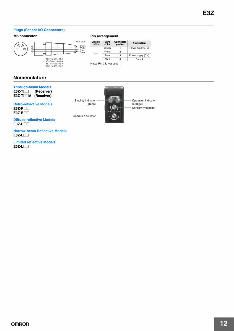
E3Z
Plugs (Sensor IO Connectors)
M8 connector Pin arrangement Wire color
24
13
1 2 3 4
Brown White Blue Black
XS3F-M421-402-A XS3F-M421-405-A XS3F-M422-402-A Note Pin 2 is not used XS3F-M422-405-A
Nomenclature
Classifi-cation
Wire color
Connector pin No Application
Brown 1 Power supply (+V)
DC White 2 minus Blue 3 Power supply (0 V)
Black 4 Output
Through-beam Models E3Z-T (Receiver) E3Z-TA (Receiver)
Stability indicator Operation indicator Retro-reflective Models (green) (orange)
Sensitivity adjusterE3Z-R E3Z-B
Operation selector Diffuse-reflective Models E3Z-D
Narrow-beam Reflective Models E3Z-L
Limited reflective Models E3Z-L
12
E3Z Safety Precautions
Refer to Warranty and Limitations of Liability
WARNING This product is not designed or rated for ensuring safety of persons either directly or indirectly Do not use it for such purposes
Precautions for Correct Use Do not use the product in atmospheres or environments that exceed product ratings
Wiring
M8 Metal Connector bull Be sure to connect or disconnect the metal connector after turning
OFF the Sensor bull Hold the connector cover to connect or disconnect the metal
connector bull Secure the connector cover by hand Do not use any pliers
otherwise the connector may be damaged bull The proper tightening torque range is between 03 and 04 Nmiddotm Be
sure to tighten the connector securely otherwise the specified degree of protection may not be maintained or the connector may be disconnected due to vibration
Mounting
Sensor Mounting Use M3 screws to mount the sensor and tighten each screw to a maximum torque of 053 Nmiddotm
E3Z- E39-L104 Mounting Bracket (sold separately)
Oil-resistant Models
Oil Resistance bull Although the E3Z-K Sensors have oil-resistant specifications
performance may be affected by certain types of oil Refer to the following table
bull E3Z-K Sensors are tested for resistance to the oils given in the following table Refer to the information in the table when deciding which type of oil to use
Test oil clas-sification Product name
Kinematic viscosity (mm2s) at 40degC
pH
Lubricant Velocity No3 (manufactured by Exx-on Mobil)
202
---Water insolu-ble machining oil
Yushiron Oil No2 ac (manufactured by Yushiro Chemical In-dustry Co Ltd)
Less than 10
Yushiroken EC50T-3 (manufactured by Yushiro Chemical In-dustry Co Ltd)
7 to 95
Water soluble
Yushiron Lubic HWC68 (manufactured by Yushiro Chemical In-dustry Co Ltd)
---
7 to 99
machining oil Gryton 1700D (manufactured by Toho Chemical Industry Co Ltd) Yushironken S50N (manufactured by Yushiro Chemical In-dustry Co Ltd)
7 to 92
7 to 98
Note 1 The E3Z maintained a minimum insulation resistance of 100 MΩ after it was dipped in all the above oils for 240 hours
2 When using the Sensors in environments subject to oils other than those listed above use the figures for kinematic viscosity and pH from the table as general guidelines Additives and other substances contained in oils may affect the E3Z Be sure to consider this before use
13
---
---
---
---
E3Z (Unit mm)Dimensions Tolerance class IT16 applies to dimensions in this data sheet unless otherwise specified
Sensors
Through-beam Pre-wired Models E3Z-T61(K) E3Z-T81(K) E3Z-T61A E3Z-T81A E3Z-T62 E3Z-T82
2020
12
328
254
127
4 dia vinyl-insulated round cable with 2 conductors (Conductor cross section 02 mm2 (AWG24) Insulator diameter 11 mm) Standard length 2 m
Two M3
Power indicator (orange)
Emitter
Lens
3131 11
21
108108
72
Terminal No
Specifi-cations
1 +V
2 3 0V
4
M8 Pre-wired Connector (E3Z-TK-M3J)
4 dia vinyl-insulated round cable with
Pins 2 and 4 are not used 2 or 3 conductors Standard length 03 m
M8
2 4
1 3
The Emitter cable has two conductors and the Receiver cable has three conductors
2020 328
254
127
4 dia vinyl-insulated round cable with 3 conductors (Conductor cross section 02 mm2 (AWG24) Insulator diameter11 mm) Standard length 2 m
Two M3
45112
Stability indicator (green)
Operation Indicator (orange) 75
Sensitivity adjuster
Operation selector
Receiver
Lens
11
21
3131
108108
72
Pin 2 is not used
Terminal No
Specifi-cations
1 +V
2 ---
3 0V
4 Output
Through-beam Connector Models E3Z-T66 E3Z-T86 E3Z-T66A E3Z-T86A E3Z-T67 E3Z-T87
M8 connector
104 Two M3
Lens
3131 11
Power indicator (orange)
Emitter
12
202021
127
108108
72 328
254
Terminal No
Specifi-cations
1 +V
2
3 0V
4
Pins 2 and 4 are not used975
45 Operation Indicator (orange)
112 Operation selector
Receiver
Stability indicator (green) Sensitivity adjuster
Lens
127
2543131 11
Two M3 104
M8 connector
Pin 2 is not used975
28
75
2020
108108
7221 3
Terminal No
Specifi-cations
1 +V
2 ---
3 0V
4 Output
Models numbers for Through-beam Sensors (E3Z-T) are for sets that include both the Emitter and Receiver The model number of the Emitter is expressed by adding -L to the set model number (example E3Z-T61-L 2M) the model number of the Receiver by adding -D (example E3Z-T61-D 2M) Refer to Ordering Information to confirm model numbers for Emitter and Receivers
14
E3Z
Retro-reflective Models Pre-wired Models E3Z-R61(K) E3Z-B61 E3Z-R81(K) E3Z-B81 E3Z-D61(K) E3Z-B62 E3Z-D81(K) E3Z-B82 E3Z-D62(K) E3Z-L63 E3Z-D82(K) E3Z-L83 E3Z-L61 E3Z-L81 28
254
4 dia vinyl-insulated round cable with 3 conductors (Conductor cross section 02 mm2 (AWG24) Insulator diameter11 mm) Standard length 2 m
Stability indicator (green)
Two M3
Sensitivity adjuster
Operation selector
Operation Indicator (orange)
21
3131
Receiver Lens 7 dia
Emitter Lens 7 dia
2020
167
108108
328
45112
75
2548
M8 Pre-wired Connector (E3Z-TK-M3J)
4 dia vinyl-insulated round cable with 3 conductors Standard length 03 m
M8
2 4
1 3
Terminal No
Specifica-tions
1 +V
2 ---
3 0V
4 Output
Retro-reflective Models Connector Models E3Z-R66 E3Z-B66 E3Z-R86 E3Z-B86 E3Z-D66 E3Z-B67 E3Z-D86 E3Z-B87 E3Z-D67 E3Z-L68 E3Z-D87 E3Z-L88 E3Z-L66 E3Z-L86
Stability indicator (green)
Two M3
975
Receiver Lens 7 dia
Emitter Lens 7 dia
Sensitivity adjuster
M8 connector
Operation selector
Operation Indicator (orange)
2020
167
108108
104
21
3131
28
254
45112
75
3
8
Terminal No
Specifica-tions
1 +V
2 ---
3 0V
4 Output
Note The lens for the E3Z-D1D6LB is red The lens for the E3Z-D2D7 is black
15
E3Z
Accessories (Order Separately) Slits E39-S65A E39-S65B E39-S65C
A
322322
202202
02-mm-thick
104104
127
Model Size A Material E39-S65A 05 dia SUS301
stainless steel
E39-S65B 10 dia E39-S65C 20 dia
Slits E39-S65D E39-S65E E39-S65F
Model Size A Material E39-S65D 05 SUS301
stainless steel
E39-S65E 10 E39-S65F 20
A
322322 10
02-mm-thick
104104
202202
127
Slits E39-L44
162
195
141 87
2727
312312
3636
3
3
18
18
232
262
20deg
(Mounting dimensions) Slits E39-L104
67
70
1
456 2929
178
266266
124
R20 14deg
215
3939
10deg
88
(Mounting dimensions)
Mounting Brackets
Refer to E39-R for details
Sensor IO Connectors
Refer to XS3 for details
16
Terms and Conditions of Sale 1 Offer Acceptance These terms and conditions (these Terms) are deemed
part of all quotes agreements purchase orders acknowledgments price lists catalogs manuals brochures and other documents whether electronic or in writing relating to the sale of products or services (collectively the Products) by Omron Electronics LLC and its subsidiary companies (ldquoOmronrdquo) Omron objects to any terms or conditions proposed in Buyerrsquos purchase order or other documents which are inconsistent with or in addition to these Terms
2 Prices Payment Terms All prices stated are current subject to change with-out notice by Omron Omron reserves the right to increase or decrease prices on any unshipped portions of outstanding orders Payments for Products are due net 30 days unless otherwise stated in the invoice
3 Discounts Cash discounts if any will apply only on the net amount of invoices sent to Buyer after deducting transportation charges taxes and duties and will be allowed only if (i) the invoice is paid according to Omronrsquos payment terms and (ii) Buyer has no past due amounts
4 Interest Omron at its option may charge Buyer 1-12 interest per month or the maximum legal rate whichever is less on any balance not paid within the stated terms
5 Orders Omron will accept no order less than $200 net billing 6 Governmental Approvals Buyer shall be responsible for and shall bear all
costs involved in obtaining any government approvals required for the impor-tation or sale of the Products
7 Taxes All taxes duties and other governmental charges (other than general real property and income taxes) including any interest or penalties thereon imposed directly or indirectly on Omron or required to be collected directly or indirectly by Omron for the manufacture production sale delivery importa-tion consumption or use of the Products sold hereunder (including customs duties and sales excise use turnover and license taxes) shall be charged to and remitted by Buyer to Omron
8 Financial If the financial position of Buyer at any time becomes unsatisfactory to Omron Omron reserves the right to stop shipments or require satisfactory security or payment in advance If Buyer fails to make payment or otherwise comply with these Terms or any related agreement Omron may (without liabil-ity and in addition to other remedies) cancel any unshipped portion of Prod-ucts sold hereunder and stop any Products in transit until Buyer pays all amounts including amounts payable hereunder whether or not then due which are owing to it by Buyer Buyer shall in any event remain liable for all unpaid accounts
9 Cancellation Etc Orders are not subject to rescheduling or cancellation unless Buyer indemnifies Omron against all related costs or expenses
10 Force Majeure Omron shall not be liable for any delay or failure in delivery resulting from causes beyond its control including earthquakes fires floods strikes or other labor disputes shortage of labor or materials accidents to machinery acts of sabotage riots delay in or lack of transportation or the requirements of any government authority
11 Shipping Delivery Unless otherwise expressly agreed in writing by Omron a Shipments shall be by a carrier selected by Omron Omron will not drop ship
except in ldquobreak downrdquo situations b Such carrier shall act as the agent of Buyer and delivery to such carrier shall
constitute delivery to Buyer c All sales and shipments of Products shall be FOB shipping point (unless oth-
erwise stated in writing by Omron) at which point title and risk of loss shall pass from Omron to Buyer provided that Omron shall retain a security inter-est in the Products until the full purchase price is paid
d Delivery and shipping dates are estimates only and e Omron will package Products as it deems proper for protection against nor-
mal handling and extra charges apply to special conditions 12 Claims Any claim by Buyer against Omron for shortage or damage to the
Products occurring before delivery to the carrier must be presented in writing to Omron within 30 days of receipt of shipment and include the original trans-portation bill signed by the carrier noting that the carrier received the Products from Omron in the condition claimed
13 Warranties (a) Exclusive Warranty Omronrsquos exclusive warranty is that the Products will be free from defects in materials and workmanship for a period of twelve months from the date of sale by Omron (or such other period expressed in writing by Omron) Omron disclaims all other warranties express or implied (b) Limitations OMRON MAKES NO WARRANTY OR REPRESENTATION EXPRESS OR IMPLIED ABOUT NON-INFRINGEMENT MERCHANTABIL-
ITY OR FITNESS FOR A PARTICULAR PURPOSE OF THE PRODUCTS BUYER ACKNOWLEDGES THAT IT ALONE HAS DETERMINED THAT THE PRODUCTS WILL SUITABLY MEET THE REQUIREMENTS OF THEIR INTENDED USE Omron further disclaims all warranties and responsibility of any type for claims or expenses based on infringement by the Products or oth-erwise of any intellectual property right (c) Buyer Remedy Omronrsquos sole obli-gation hereunder shall be at Omronrsquos election to (i) replace (in the form originally shipped with Buyer responsible for labor charges for removal or replacement thereof) the non-complying Product (ii) repair the non-complying Product or (iii) repay or credit Buyer an amount equal to the purchase price of the non-complying Product provided that in no event shall Omron be responsi-ble for warranty repair indemnity or any other claims or expenses regarding the Products unless Omronrsquos analysis confirms that the Products were prop-erly handled stored installed and maintained and not subject to contamina-tion abuse misuse or inappropriate modification Return of any Products by Buyer must be approved in writing by Omron before shipment Omron Compa-nies shall not be liable for the suitability or unsuitability or the results from the use of Products in combination with any electrical or electronic components circuits system assemblies or any other materials or substances or environ-ments Any advice recommendations or information given orally or in writing are not to be construed as an amendment or addition to the above warranty See httpwwwomron247com or contact your Omron representative for pub-lished information
14 Limitation on Liability Etc OMRON COMPANIES SHALL NOT BE LIABLE FOR SPECIAL INDIRECT INCIDENTAL OR CONSEQUENTIAL DAMAGES LOSS OF PROFITS OR PRODUCTION OR COMMERCIAL LOSS IN ANY WAY CONNECTED WITH THE PRODUCTS WHETHER SUCH CLAIM IS BASED IN CONTRACT WARRANTY NEGLIGENCE OR STRICT LIABILITY Further in no event shall liability of Omron Companies exceed the individual price of the Product on which liability is asserted
15 Indemnities Buyer shall indemnify and hold harmless Omron Companies and their employees from and against all liabilities losses claims costs and expenses (including attorneys fees and expenses) related to any claim inves-tigation litigation or proceeding (whether or not Omron is a party) which arises or is alleged to arise from Buyers acts or omissions under these Terms or in any way with respect to the Products Without limiting the foregoing Buyer (at its own expense) shall indemnify and hold harmless Omron and defend or set-tle any action brought against such Companies to the extent based on a claim that any Product made to Buyer specifications infringed intellectual property rights of another party
16 Property Confidentiality Any intellectual property in the Products is the exclu-sive property of Omron Companies and Buyer shall not attempt to duplicate it in any way without the written permission of Omron Notwithstanding any charges to Buyer for engineering or tooling all engineering and tooling shall remain the exclusive property of Omron All information and materials supplied by Omron to Buyer relating to the Products are confidential and proprietary and Buyer shall limit distribution thereof to its trusted employees and strictly prevent disclosure to any third party
17 Export Controls Buyer shall comply with all applicable laws regulations and licenses regarding (i) export of products or information (iii) sale of products to ldquoforbiddenrdquo or other proscribed persons and (ii) disclosure to non-citizens of regulated technology or information
18 Miscellaneous (a) Waiver No failure or delay by Omron in exercising any right and no course of dealing between Buyer and Omron shall operate as a waiver of rights by Omron (b) Assignment Buyer may not assign its rights hereunder without Omrons written consent (c) Law These Terms are governed by the law of the jurisdiction of the home office of the Omron company from which Buyer is purchasing the Products (without regard to conflict of law princi-ples) (d) Amendment These Terms constitute the entire agreement between Buyer and Omron relating to the Products and no provision may be changed or waived unless in writing signed by the parties (e) Severability If any provi-sion hereof is rendered ineffective or invalid such provision shall not invalidate any other provision (f) Setoff Buyer shall have no right to set off any amounts against the amount owing in respect of this invoice (g) Definitions As used herein ldquoincludingrdquo means ldquoincluding without limitationrdquo and ldquoOmron Compa-niesrdquo (or similar words) mean Omron Corporation and any direct or indirect subsidiary or affiliate thereof
Certain Precautions on Specifications and Use 1 Suitability of Use Omron Companies shall not be responsible for conformity ADDRESS THE RISKS AND THAT THE OMRONrsquoS PRODUCT IS PROP-
with any standards codes or regulations which apply to the combination of the ERLY RATED AND INSTALLED FOR THE INTENDED USE WITHIN THE Product in the Buyerrsquos application or use of the Product At Buyerrsquos request Omron will provide applicable third party certification documents identifying 2
OVERALL EQUIPMENT OR SYSTEM Programmable Products Omron Companies shall not be responsible for the
ratings and limitations of use which apply to the Product This information by userrsquos programming of a programmable Product or any consequence thereof itself is not sufficient for a complete determination of the suitability of the Prod- 3 Performance Data Data presented in Omron Company websites catalogs uct in combination with the end product machine system or other application or use Buyer shall be solely responsible for determining appropriateness of
and other materials is provided as a guide for the user in determining suitabil-ity and does not constitute a warranty It may represent the result of Omronrsquos
the particular Product with respect to Buyerrsquos application product or system test conditions and the user must correlate it to actual application require-Buyer shall take application responsibility in all cases but the following is a ments Actual performance is subject to the Omronrsquos Warranty and Limitations non-exhaustive list of applications for which particular attention must be given (i) Outdoor use uses involving potential chemical contamination or electrical 4
of Liability Change in Specifications Product specifications and accessories may be
interference or conditions or uses not described in this document changed at any time based on improvements and other reasons It is our prac-(ii) Use in consumer products or any use in significant quantities tice to change part numbers when published ratings or features are changed (iii) Energy control systems combustion systems railroad systems aviation systems medical equipment amusement machines vehicles safety equip-
or when significant construction changes are made However some specifica-tions of the Product may be changed without any notice When in doubt spe-
ment and installations subject to separate industry or government regulations cial part numbers may be assigned to fix or establish key specifications for (iv) Systems machines and equipment that could present a risk to life or prop- your application Please consult with your Omronrsquos representative at any time erty Please know and observe all prohibitions of use applicable to this Prod-uct 5
to confirm actual specifications of purchased Product Errors and Omissions Information presented by Omron Companies has been
NEVER USE THE PRODUCT FOR AN APPLICATION INVOLVING SERIOUS checked and is believed to be accurate however no responsibility is assumed RISK TO LIFE OR PROPERTY OR IN LARGE QUANTITIES WITHOUT for clerical typographical or proofreading errors or omissions ENSURING THAT THE SYSTEM AS A WHOLE HAS BEEN DESIGNED TO
OMRON AUTOMATION AND SAFETY THE AMERICAS HEADQUARTERS Chicago IL USA 8478437900 8005566766 wwwomron247com
OMRON CANADA INC HEAD OFFICE OMRON ARGENTINA SALES OFFICE Toronto ON Canada 4162866465 8669866766 wwwomron247com Cono Sur 541147835300
OMRON ELECTRONICS DE MEXICO HEAD OFFICE OMRON CHILE SALES OFFICE Meacutexico DF 525559014300 01-800-226-6766 melaomroncom Santiago 56999173920
OMRON ELECTRONICS DE MEXICO SALES OFFICE OTHER OMRON LATIN AMERICA SALES Apodaca NL 528111569920 01-800-226-6766 melaomroncom 541147835300
OMRON ELETROcircNICA DO BRASIL LTDA HEAD OFFICE Satildeo Paulo SP Brasil 551121016300 wwwomroncombr
OMRON EUROPE BV Wegalaan 67-69 NL-2132 JD Hoofddorp The Netherlands +31 (0) 23 568 13 00 wwwindustrialomroneu
Authorized Distributor Automation Control Systems Machine Automation Controllers (MAC) Programmable Controllers (PLC) Operator interfaces (HMI) Distributed IO Software
Drives amp Motion Controls Servo amp AC Drives Motion Controllers amp Encoders
Temperature amp Process Controllers Single and Multi-loop Controllers
Sensors amp Vision Proximity Sensors Photoelectric Sensors Fiber-Optic Sensors Amplified Photomicrosensors Measurement Sensors Ultrasonic Sensors Vision Sensors
Industrial Components RFIDCode Readers Relays Pushbuttons amp Indicators Limit and Basic Switches Timers Counters Metering Devices Power Supplies
Safety Laser Scanners Safety Mats Edges and Bumpers Programmable Safety
Controllers Light Curtains Safety Relays Safety Interlock Switches
CSM_E3Z_DS_E_18_1 1114 Note Specifications are subject to change copy 2015 Omron Electronics LLC Printed in USA
Printed on recycled paper

---
---
---
---
E3Z (Unit mm)Dimensions Tolerance class IT16 applies to dimensions in this data sheet unless otherwise specified
Sensors
Through-beam Pre-wired Models E3Z-T61(K) E3Z-T81(K) E3Z-T61A E3Z-T81A E3Z-T62 E3Z-T82
2020
12
328
254
127
4 dia vinyl-insulated round cable with 2 conductors (Conductor cross section 02 mm2 (AWG24) Insulator diameter 11 mm) Standard length 2 m
Two M3
Power indicator (orange)
Emitter
Lens
3131 11
21
108108
72
Terminal No
Specifi-cations
1 +V
2 3 0V
4
M8 Pre-wired Connector (E3Z-TK-M3J)
4 dia vinyl-insulated round cable with
Pins 2 and 4 are not used 2 or 3 conductors Standard length 03 m
M8
2 4
1 3
The Emitter cable has two conductors and the Receiver cable has three conductors
2020 328
254
127
4 dia vinyl-insulated round cable with 3 conductors (Conductor cross section 02 mm2 (AWG24) Insulator diameter11 mm) Standard length 2 m
Two M3
45112
Stability indicator (green)
Operation Indicator (orange) 75
Sensitivity adjuster
Operation selector
Receiver
Lens
11
21
3131
108108
72
Pin 2 is not used
Terminal No
Specifi-cations
1 +V
2 ---
3 0V
4 Output
Through-beam Connector Models E3Z-T66 E3Z-T86 E3Z-T66A E3Z-T86A E3Z-T67 E3Z-T87
M8 connector
104 Two M3
Lens
3131 11
Power indicator (orange)
Emitter
12
202021
127
108108
72 328
254
Terminal No
Specifi-cations
1 +V
2
3 0V
4
Pins 2 and 4 are not used975
45 Operation Indicator (orange)
112 Operation selector
Receiver
Stability indicator (green) Sensitivity adjuster
Lens
127
2543131 11
Two M3 104
M8 connector
Pin 2 is not used975
28
75
2020
108108
7221 3
Terminal No
Specifi-cations
1 +V
2 ---
3 0V
4 Output
Models numbers for Through-beam Sensors (E3Z-T) are for sets that include both the Emitter and Receiver The model number of the Emitter is expressed by adding -L to the set model number (example E3Z-T61-L 2M) the model number of the Receiver by adding -D (example E3Z-T61-D 2M) Refer to Ordering Information to confirm model numbers for Emitter and Receivers
14
E3Z
Retro-reflective Models Pre-wired Models E3Z-R61(K) E3Z-B61 E3Z-R81(K) E3Z-B81 E3Z-D61(K) E3Z-B62 E3Z-D81(K) E3Z-B82 E3Z-D62(K) E3Z-L63 E3Z-D82(K) E3Z-L83 E3Z-L61 E3Z-L81 28
254
4 dia vinyl-insulated round cable with 3 conductors (Conductor cross section 02 mm2 (AWG24) Insulator diameter11 mm) Standard length 2 m
Stability indicator (green)
Two M3
Sensitivity adjuster
Operation selector
Operation Indicator (orange)
21
3131
Receiver Lens 7 dia
Emitter Lens 7 dia
2020
167
108108
328
45112
75
2548
M8 Pre-wired Connector (E3Z-TK-M3J)
4 dia vinyl-insulated round cable with 3 conductors Standard length 03 m
M8
2 4
1 3
Terminal No
Specifica-tions
1 +V
2 ---
3 0V
4 Output
Retro-reflective Models Connector Models E3Z-R66 E3Z-B66 E3Z-R86 E3Z-B86 E3Z-D66 E3Z-B67 E3Z-D86 E3Z-B87 E3Z-D67 E3Z-L68 E3Z-D87 E3Z-L88 E3Z-L66 E3Z-L86
Stability indicator (green)
Two M3
975
Receiver Lens 7 dia
Emitter Lens 7 dia
Sensitivity adjuster
M8 connector
Operation selector
Operation Indicator (orange)
2020
167
108108
104
21
3131
28
254
45112
75
3
8
Terminal No
Specifica-tions
1 +V
2 ---
3 0V
4 Output
Note The lens for the E3Z-D1D6LB is red The lens for the E3Z-D2D7 is black
15
E3Z
Accessories (Order Separately) Slits E39-S65A E39-S65B E39-S65C
A
322322
202202
02-mm-thick
104104
127
Model Size A Material E39-S65A 05 dia SUS301
stainless steel
E39-S65B 10 dia E39-S65C 20 dia
Slits E39-S65D E39-S65E E39-S65F
Model Size A Material E39-S65D 05 SUS301
stainless steel
E39-S65E 10 E39-S65F 20
A
322322 10
02-mm-thick
104104
202202
127
Slits E39-L44
162
195
141 87
2727
312312
3636
3
3
18
18
232
262
20deg
(Mounting dimensions) Slits E39-L104
67
70
1
456 2929
178
266266
124
R20 14deg
215
3939
10deg
88
(Mounting dimensions)
Mounting Brackets
Refer to E39-R for details
Sensor IO Connectors
Refer to XS3 for details
16
Terms and Conditions of Sale 1 Offer Acceptance These terms and conditions (these Terms) are deemed
part of all quotes agreements purchase orders acknowledgments price lists catalogs manuals brochures and other documents whether electronic or in writing relating to the sale of products or services (collectively the Products) by Omron Electronics LLC and its subsidiary companies (ldquoOmronrdquo) Omron objects to any terms or conditions proposed in Buyerrsquos purchase order or other documents which are inconsistent with or in addition to these Terms
2 Prices Payment Terms All prices stated are current subject to change with-out notice by Omron Omron reserves the right to increase or decrease prices on any unshipped portions of outstanding orders Payments for Products are due net 30 days unless otherwise stated in the invoice
3 Discounts Cash discounts if any will apply only on the net amount of invoices sent to Buyer after deducting transportation charges taxes and duties and will be allowed only if (i) the invoice is paid according to Omronrsquos payment terms and (ii) Buyer has no past due amounts
4 Interest Omron at its option may charge Buyer 1-12 interest per month or the maximum legal rate whichever is less on any balance not paid within the stated terms
5 Orders Omron will accept no order less than $200 net billing 6 Governmental Approvals Buyer shall be responsible for and shall bear all
costs involved in obtaining any government approvals required for the impor-tation or sale of the Products
7 Taxes All taxes duties and other governmental charges (other than general real property and income taxes) including any interest or penalties thereon imposed directly or indirectly on Omron or required to be collected directly or indirectly by Omron for the manufacture production sale delivery importa-tion consumption or use of the Products sold hereunder (including customs duties and sales excise use turnover and license taxes) shall be charged to and remitted by Buyer to Omron
8 Financial If the financial position of Buyer at any time becomes unsatisfactory to Omron Omron reserves the right to stop shipments or require satisfactory security or payment in advance If Buyer fails to make payment or otherwise comply with these Terms or any related agreement Omron may (without liabil-ity and in addition to other remedies) cancel any unshipped portion of Prod-ucts sold hereunder and stop any Products in transit until Buyer pays all amounts including amounts payable hereunder whether or not then due which are owing to it by Buyer Buyer shall in any event remain liable for all unpaid accounts
9 Cancellation Etc Orders are not subject to rescheduling or cancellation unless Buyer indemnifies Omron against all related costs or expenses
10 Force Majeure Omron shall not be liable for any delay or failure in delivery resulting from causes beyond its control including earthquakes fires floods strikes or other labor disputes shortage of labor or materials accidents to machinery acts of sabotage riots delay in or lack of transportation or the requirements of any government authority
11 Shipping Delivery Unless otherwise expressly agreed in writing by Omron a Shipments shall be by a carrier selected by Omron Omron will not drop ship
except in ldquobreak downrdquo situations b Such carrier shall act as the agent of Buyer and delivery to such carrier shall
constitute delivery to Buyer c All sales and shipments of Products shall be FOB shipping point (unless oth-
erwise stated in writing by Omron) at which point title and risk of loss shall pass from Omron to Buyer provided that Omron shall retain a security inter-est in the Products until the full purchase price is paid
d Delivery and shipping dates are estimates only and e Omron will package Products as it deems proper for protection against nor-
mal handling and extra charges apply to special conditions 12 Claims Any claim by Buyer against Omron for shortage or damage to the
Products occurring before delivery to the carrier must be presented in writing to Omron within 30 days of receipt of shipment and include the original trans-portation bill signed by the carrier noting that the carrier received the Products from Omron in the condition claimed
13 Warranties (a) Exclusive Warranty Omronrsquos exclusive warranty is that the Products will be free from defects in materials and workmanship for a period of twelve months from the date of sale by Omron (or such other period expressed in writing by Omron) Omron disclaims all other warranties express or implied (b) Limitations OMRON MAKES NO WARRANTY OR REPRESENTATION EXPRESS OR IMPLIED ABOUT NON-INFRINGEMENT MERCHANTABIL-
ITY OR FITNESS FOR A PARTICULAR PURPOSE OF THE PRODUCTS BUYER ACKNOWLEDGES THAT IT ALONE HAS DETERMINED THAT THE PRODUCTS WILL SUITABLY MEET THE REQUIREMENTS OF THEIR INTENDED USE Omron further disclaims all warranties and responsibility of any type for claims or expenses based on infringement by the Products or oth-erwise of any intellectual property right (c) Buyer Remedy Omronrsquos sole obli-gation hereunder shall be at Omronrsquos election to (i) replace (in the form originally shipped with Buyer responsible for labor charges for removal or replacement thereof) the non-complying Product (ii) repair the non-complying Product or (iii) repay or credit Buyer an amount equal to the purchase price of the non-complying Product provided that in no event shall Omron be responsi-ble for warranty repair indemnity or any other claims or expenses regarding the Products unless Omronrsquos analysis confirms that the Products were prop-erly handled stored installed and maintained and not subject to contamina-tion abuse misuse or inappropriate modification Return of any Products by Buyer must be approved in writing by Omron before shipment Omron Compa-nies shall not be liable for the suitability or unsuitability or the results from the use of Products in combination with any electrical or electronic components circuits system assemblies or any other materials or substances or environ-ments Any advice recommendations or information given orally or in writing are not to be construed as an amendment or addition to the above warranty See httpwwwomron247com or contact your Omron representative for pub-lished information
14 Limitation on Liability Etc OMRON COMPANIES SHALL NOT BE LIABLE FOR SPECIAL INDIRECT INCIDENTAL OR CONSEQUENTIAL DAMAGES LOSS OF PROFITS OR PRODUCTION OR COMMERCIAL LOSS IN ANY WAY CONNECTED WITH THE PRODUCTS WHETHER SUCH CLAIM IS BASED IN CONTRACT WARRANTY NEGLIGENCE OR STRICT LIABILITY Further in no event shall liability of Omron Companies exceed the individual price of the Product on which liability is asserted
15 Indemnities Buyer shall indemnify and hold harmless Omron Companies and their employees from and against all liabilities losses claims costs and expenses (including attorneys fees and expenses) related to any claim inves-tigation litigation or proceeding (whether or not Omron is a party) which arises or is alleged to arise from Buyers acts or omissions under these Terms or in any way with respect to the Products Without limiting the foregoing Buyer (at its own expense) shall indemnify and hold harmless Omron and defend or set-tle any action brought against such Companies to the extent based on a claim that any Product made to Buyer specifications infringed intellectual property rights of another party
16 Property Confidentiality Any intellectual property in the Products is the exclu-sive property of Omron Companies and Buyer shall not attempt to duplicate it in any way without the written permission of Omron Notwithstanding any charges to Buyer for engineering or tooling all engineering and tooling shall remain the exclusive property of Omron All information and materials supplied by Omron to Buyer relating to the Products are confidential and proprietary and Buyer shall limit distribution thereof to its trusted employees and strictly prevent disclosure to any third party
17 Export Controls Buyer shall comply with all applicable laws regulations and licenses regarding (i) export of products or information (iii) sale of products to ldquoforbiddenrdquo or other proscribed persons and (ii) disclosure to non-citizens of regulated technology or information
18 Miscellaneous (a) Waiver No failure or delay by Omron in exercising any right and no course of dealing between Buyer and Omron shall operate as a waiver of rights by Omron (b) Assignment Buyer may not assign its rights hereunder without Omrons written consent (c) Law These Terms are governed by the law of the jurisdiction of the home office of the Omron company from which Buyer is purchasing the Products (without regard to conflict of law princi-ples) (d) Amendment These Terms constitute the entire agreement between Buyer and Omron relating to the Products and no provision may be changed or waived unless in writing signed by the parties (e) Severability If any provi-sion hereof is rendered ineffective or invalid such provision shall not invalidate any other provision (f) Setoff Buyer shall have no right to set off any amounts against the amount owing in respect of this invoice (g) Definitions As used herein ldquoincludingrdquo means ldquoincluding without limitationrdquo and ldquoOmron Compa-niesrdquo (or similar words) mean Omron Corporation and any direct or indirect subsidiary or affiliate thereof
Certain Precautions on Specifications and Use 1 Suitability of Use Omron Companies shall not be responsible for conformity ADDRESS THE RISKS AND THAT THE OMRONrsquoS PRODUCT IS PROP-
with any standards codes or regulations which apply to the combination of the ERLY RATED AND INSTALLED FOR THE INTENDED USE WITHIN THE Product in the Buyerrsquos application or use of the Product At Buyerrsquos request Omron will provide applicable third party certification documents identifying 2
OVERALL EQUIPMENT OR SYSTEM Programmable Products Omron Companies shall not be responsible for the
ratings and limitations of use which apply to the Product This information by userrsquos programming of a programmable Product or any consequence thereof itself is not sufficient for a complete determination of the suitability of the Prod- 3 Performance Data Data presented in Omron Company websites catalogs uct in combination with the end product machine system or other application or use Buyer shall be solely responsible for determining appropriateness of
and other materials is provided as a guide for the user in determining suitabil-ity and does not constitute a warranty It may represent the result of Omronrsquos
the particular Product with respect to Buyerrsquos application product or system test conditions and the user must correlate it to actual application require-Buyer shall take application responsibility in all cases but the following is a ments Actual performance is subject to the Omronrsquos Warranty and Limitations non-exhaustive list of applications for which particular attention must be given (i) Outdoor use uses involving potential chemical contamination or electrical 4
of Liability Change in Specifications Product specifications and accessories may be
interference or conditions or uses not described in this document changed at any time based on improvements and other reasons It is our prac-(ii) Use in consumer products or any use in significant quantities tice to change part numbers when published ratings or features are changed (iii) Energy control systems combustion systems railroad systems aviation systems medical equipment amusement machines vehicles safety equip-
or when significant construction changes are made However some specifica-tions of the Product may be changed without any notice When in doubt spe-
ment and installations subject to separate industry or government regulations cial part numbers may be assigned to fix or establish key specifications for (iv) Systems machines and equipment that could present a risk to life or prop- your application Please consult with your Omronrsquos representative at any time erty Please know and observe all prohibitions of use applicable to this Prod-uct 5
to confirm actual specifications of purchased Product Errors and Omissions Information presented by Omron Companies has been
NEVER USE THE PRODUCT FOR AN APPLICATION INVOLVING SERIOUS checked and is believed to be accurate however no responsibility is assumed RISK TO LIFE OR PROPERTY OR IN LARGE QUANTITIES WITHOUT for clerical typographical or proofreading errors or omissions ENSURING THAT THE SYSTEM AS A WHOLE HAS BEEN DESIGNED TO
OMRON AUTOMATION AND SAFETY THE AMERICAS HEADQUARTERS Chicago IL USA 8478437900 8005566766 wwwomron247com
OMRON CANADA INC HEAD OFFICE OMRON ARGENTINA SALES OFFICE Toronto ON Canada 4162866465 8669866766 wwwomron247com Cono Sur 541147835300
OMRON ELECTRONICS DE MEXICO HEAD OFFICE OMRON CHILE SALES OFFICE Meacutexico DF 525559014300 01-800-226-6766 melaomroncom Santiago 56999173920
OMRON ELECTRONICS DE MEXICO SALES OFFICE OTHER OMRON LATIN AMERICA SALES Apodaca NL 528111569920 01-800-226-6766 melaomroncom 541147835300
OMRON ELETROcircNICA DO BRASIL LTDA HEAD OFFICE Satildeo Paulo SP Brasil 551121016300 wwwomroncombr
OMRON EUROPE BV Wegalaan 67-69 NL-2132 JD Hoofddorp The Netherlands +31 (0) 23 568 13 00 wwwindustrialomroneu
Authorized Distributor Automation Control Systems Machine Automation Controllers (MAC) Programmable Controllers (PLC) Operator interfaces (HMI) Distributed IO Software
Drives amp Motion Controls Servo amp AC Drives Motion Controllers amp Encoders
Temperature amp Process Controllers Single and Multi-loop Controllers
Sensors amp Vision Proximity Sensors Photoelectric Sensors Fiber-Optic Sensors Amplified Photomicrosensors Measurement Sensors Ultrasonic Sensors Vision Sensors
Industrial Components RFIDCode Readers Relays Pushbuttons amp Indicators Limit and Basic Switches Timers Counters Metering Devices Power Supplies
Safety Laser Scanners Safety Mats Edges and Bumpers Programmable Safety
Controllers Light Curtains Safety Relays Safety Interlock Switches
CSM_E3Z_DS_E_18_1 1114 Note Specifications are subject to change copy 2015 Omron Electronics LLC Printed in USA
Printed on recycled paper

E3Z
Accessories (Order Separately) Slits E39-S65A E39-S65B E39-S65C
A
322322
202202
02-mm-thick
104104
127
Model Size A Material E39-S65A 05 dia SUS301
stainless steel
E39-S65B 10 dia E39-S65C 20 dia
Slits E39-S65D E39-S65E E39-S65F
Model Size A Material E39-S65D 05 SUS301
stainless steel
E39-S65E 10 E39-S65F 20
A
322322 10
02-mm-thick
104104
202202
127
Slits E39-L44
162
195
141 87
2727
312312
3636
3
3
18
18
232
262
20deg
(Mounting dimensions) Slits E39-L104
67
70
1
456 2929
178
266266
124
R20 14deg
215
3939
10deg
88
(Mounting dimensions)
Mounting Brackets
Refer to E39-R for details
Sensor IO Connectors
Refer to XS3 for details
16
Terms and Conditions of Sale 1 Offer Acceptance These terms and conditions (these Terms) are deemed
part of all quotes agreements purchase orders acknowledgments price lists catalogs manuals brochures and other documents whether electronic or in writing relating to the sale of products or services (collectively the Products) by Omron Electronics LLC and its subsidiary companies (ldquoOmronrdquo) Omron objects to any terms or conditions proposed in Buyerrsquos purchase order or other documents which are inconsistent with or in addition to these Terms
2 Prices Payment Terms All prices stated are current subject to change with-out notice by Omron Omron reserves the right to increase or decrease prices on any unshipped portions of outstanding orders Payments for Products are due net 30 days unless otherwise stated in the invoice
3 Discounts Cash discounts if any will apply only on the net amount of invoices sent to Buyer after deducting transportation charges taxes and duties and will be allowed only if (i) the invoice is paid according to Omronrsquos payment terms and (ii) Buyer has no past due amounts
4 Interest Omron at its option may charge Buyer 1-12 interest per month or the maximum legal rate whichever is less on any balance not paid within the stated terms
5 Orders Omron will accept no order less than $200 net billing 6 Governmental Approvals Buyer shall be responsible for and shall bear all
costs involved in obtaining any government approvals required for the impor-tation or sale of the Products
7 Taxes All taxes duties and other governmental charges (other than general real property and income taxes) including any interest or penalties thereon imposed directly or indirectly on Omron or required to be collected directly or indirectly by Omron for the manufacture production sale delivery importa-tion consumption or use of the Products sold hereunder (including customs duties and sales excise use turnover and license taxes) shall be charged to and remitted by Buyer to Omron
8 Financial If the financial position of Buyer at any time becomes unsatisfactory to Omron Omron reserves the right to stop shipments or require satisfactory security or payment in advance If Buyer fails to make payment or otherwise comply with these Terms or any related agreement Omron may (without liabil-ity and in addition to other remedies) cancel any unshipped portion of Prod-ucts sold hereunder and stop any Products in transit until Buyer pays all amounts including amounts payable hereunder whether or not then due which are owing to it by Buyer Buyer shall in any event remain liable for all unpaid accounts
9 Cancellation Etc Orders are not subject to rescheduling or cancellation unless Buyer indemnifies Omron against all related costs or expenses
10 Force Majeure Omron shall not be liable for any delay or failure in delivery resulting from causes beyond its control including earthquakes fires floods strikes or other labor disputes shortage of labor or materials accidents to machinery acts of sabotage riots delay in or lack of transportation or the requirements of any government authority
11 Shipping Delivery Unless otherwise expressly agreed in writing by Omron a Shipments shall be by a carrier selected by Omron Omron will not drop ship
except in ldquobreak downrdquo situations b Such carrier shall act as the agent of Buyer and delivery to such carrier shall
constitute delivery to Buyer c All sales and shipments of Products shall be FOB shipping point (unless oth-
erwise stated in writing by Omron) at which point title and risk of loss shall pass from Omron to Buyer provided that Omron shall retain a security inter-est in the Products until the full purchase price is paid
d Delivery and shipping dates are estimates only and e Omron will package Products as it deems proper for protection against nor-
mal handling and extra charges apply to special conditions 12 Claims Any claim by Buyer against Omron for shortage or damage to the
Products occurring before delivery to the carrier must be presented in writing to Omron within 30 days of receipt of shipment and include the original trans-portation bill signed by the carrier noting that the carrier received the Products from Omron in the condition claimed
13 Warranties (a) Exclusive Warranty Omronrsquos exclusive warranty is that the Products will be free from defects in materials and workmanship for a period of twelve months from the date of sale by Omron (or such other period expressed in writing by Omron) Omron disclaims all other warranties express or implied (b) Limitations OMRON MAKES NO WARRANTY OR REPRESENTATION EXPRESS OR IMPLIED ABOUT NON-INFRINGEMENT MERCHANTABIL-
ITY OR FITNESS FOR A PARTICULAR PURPOSE OF THE PRODUCTS BUYER ACKNOWLEDGES THAT IT ALONE HAS DETERMINED THAT THE PRODUCTS WILL SUITABLY MEET THE REQUIREMENTS OF THEIR INTENDED USE Omron further disclaims all warranties and responsibility of any type for claims or expenses based on infringement by the Products or oth-erwise of any intellectual property right (c) Buyer Remedy Omronrsquos sole obli-gation hereunder shall be at Omronrsquos election to (i) replace (in the form originally shipped with Buyer responsible for labor charges for removal or replacement thereof) the non-complying Product (ii) repair the non-complying Product or (iii) repay or credit Buyer an amount equal to the purchase price of the non-complying Product provided that in no event shall Omron be responsi-ble for warranty repair indemnity or any other claims or expenses regarding the Products unless Omronrsquos analysis confirms that the Products were prop-erly handled stored installed and maintained and not subject to contamina-tion abuse misuse or inappropriate modification Return of any Products by Buyer must be approved in writing by Omron before shipment Omron Compa-nies shall not be liable for the suitability or unsuitability or the results from the use of Products in combination with any electrical or electronic components circuits system assemblies or any other materials or substances or environ-ments Any advice recommendations or information given orally or in writing are not to be construed as an amendment or addition to the above warranty See httpwwwomron247com or contact your Omron representative for pub-lished information
14 Limitation on Liability Etc OMRON COMPANIES SHALL NOT BE LIABLE FOR SPECIAL INDIRECT INCIDENTAL OR CONSEQUENTIAL DAMAGES LOSS OF PROFITS OR PRODUCTION OR COMMERCIAL LOSS IN ANY WAY CONNECTED WITH THE PRODUCTS WHETHER SUCH CLAIM IS BASED IN CONTRACT WARRANTY NEGLIGENCE OR STRICT LIABILITY Further in no event shall liability of Omron Companies exceed the individual price of the Product on which liability is asserted
15 Indemnities Buyer shall indemnify and hold harmless Omron Companies and their employees from and against all liabilities losses claims costs and expenses (including attorneys fees and expenses) related to any claim inves-tigation litigation or proceeding (whether or not Omron is a party) which arises or is alleged to arise from Buyers acts or omissions under these Terms or in any way with respect to the Products Without limiting the foregoing Buyer (at its own expense) shall indemnify and hold harmless Omron and defend or set-tle any action brought against such Companies to the extent based on a claim that any Product made to Buyer specifications infringed intellectual property rights of another party
16 Property Confidentiality Any intellectual property in the Products is the exclu-sive property of Omron Companies and Buyer shall not attempt to duplicate it in any way without the written permission of Omron Notwithstanding any charges to Buyer for engineering or tooling all engineering and tooling shall remain the exclusive property of Omron All information and materials supplied by Omron to Buyer relating to the Products are confidential and proprietary and Buyer shall limit distribution thereof to its trusted employees and strictly prevent disclosure to any third party
17 Export Controls Buyer shall comply with all applicable laws regulations and licenses regarding (i) export of products or information (iii) sale of products to ldquoforbiddenrdquo or other proscribed persons and (ii) disclosure to non-citizens of regulated technology or information
18 Miscellaneous (a) Waiver No failure or delay by Omron in exercising any right and no course of dealing between Buyer and Omron shall operate as a waiver of rights by Omron (b) Assignment Buyer may not assign its rights hereunder without Omrons written consent (c) Law These Terms are governed by the law of the jurisdiction of the home office of the Omron company from which Buyer is purchasing the Products (without regard to conflict of law princi-ples) (d) Amendment These Terms constitute the entire agreement between Buyer and Omron relating to the Products and no provision may be changed or waived unless in writing signed by the parties (e) Severability If any provi-sion hereof is rendered ineffective or invalid such provision shall not invalidate any other provision (f) Setoff Buyer shall have no right to set off any amounts against the amount owing in respect of this invoice (g) Definitions As used herein ldquoincludingrdquo means ldquoincluding without limitationrdquo and ldquoOmron Compa-niesrdquo (or similar words) mean Omron Corporation and any direct or indirect subsidiary or affiliate thereof
Certain Precautions on Specifications and Use 1 Suitability of Use Omron Companies shall not be responsible for conformity ADDRESS THE RISKS AND THAT THE OMRONrsquoS PRODUCT IS PROP-
with any standards codes or regulations which apply to the combination of the ERLY RATED AND INSTALLED FOR THE INTENDED USE WITHIN THE Product in the Buyerrsquos application or use of the Product At Buyerrsquos request Omron will provide applicable third party certification documents identifying 2
OVERALL EQUIPMENT OR SYSTEM Programmable Products Omron Companies shall not be responsible for the
ratings and limitations of use which apply to the Product This information by userrsquos programming of a programmable Product or any consequence thereof itself is not sufficient for a complete determination of the suitability of the Prod- 3 Performance Data Data presented in Omron Company websites catalogs uct in combination with the end product machine system or other application or use Buyer shall be solely responsible for determining appropriateness of
and other materials is provided as a guide for the user in determining suitabil-ity and does not constitute a warranty It may represent the result of Omronrsquos
the particular Product with respect to Buyerrsquos application product or system test conditions and the user must correlate it to actual application require-Buyer shall take application responsibility in all cases but the following is a ments Actual performance is subject to the Omronrsquos Warranty and Limitations non-exhaustive list of applications for which particular attention must be given (i) Outdoor use uses involving potential chemical contamination or electrical 4
of Liability Change in Specifications Product specifications and accessories may be
interference or conditions or uses not described in this document changed at any time based on improvements and other reasons It is our prac-(ii) Use in consumer products or any use in significant quantities tice to change part numbers when published ratings or features are changed (iii) Energy control systems combustion systems railroad systems aviation systems medical equipment amusement machines vehicles safety equip-
or when significant construction changes are made However some specifica-tions of the Product may be changed without any notice When in doubt spe-
ment and installations subject to separate industry or government regulations cial part numbers may be assigned to fix or establish key specifications for (iv) Systems machines and equipment that could present a risk to life or prop- your application Please consult with your Omronrsquos representative at any time erty Please know and observe all prohibitions of use applicable to this Prod-uct 5
to confirm actual specifications of purchased Product Errors and Omissions Information presented by Omron Companies has been
NEVER USE THE PRODUCT FOR AN APPLICATION INVOLVING SERIOUS checked and is believed to be accurate however no responsibility is assumed RISK TO LIFE OR PROPERTY OR IN LARGE QUANTITIES WITHOUT for clerical typographical or proofreading errors or omissions ENSURING THAT THE SYSTEM AS A WHOLE HAS BEEN DESIGNED TO
OMRON AUTOMATION AND SAFETY THE AMERICAS HEADQUARTERS Chicago IL USA 8478437900 8005566766 wwwomron247com
OMRON CANADA INC HEAD OFFICE OMRON ARGENTINA SALES OFFICE Toronto ON Canada 4162866465 8669866766 wwwomron247com Cono Sur 541147835300
OMRON ELECTRONICS DE MEXICO HEAD OFFICE OMRON CHILE SALES OFFICE Meacutexico DF 525559014300 01-800-226-6766 melaomroncom Santiago 56999173920
OMRON ELECTRONICS DE MEXICO SALES OFFICE OTHER OMRON LATIN AMERICA SALES Apodaca NL 528111569920 01-800-226-6766 melaomroncom 541147835300
OMRON ELETROcircNICA DO BRASIL LTDA HEAD OFFICE Satildeo Paulo SP Brasil 551121016300 wwwomroncombr
OMRON EUROPE BV Wegalaan 67-69 NL-2132 JD Hoofddorp The Netherlands +31 (0) 23 568 13 00 wwwindustrialomroneu
Authorized Distributor Automation Control Systems Machine Automation Controllers (MAC) Programmable Controllers (PLC) Operator interfaces (HMI) Distributed IO Software
Drives amp Motion Controls Servo amp AC Drives Motion Controllers amp Encoders
Temperature amp Process Controllers Single and Multi-loop Controllers
Sensors amp Vision Proximity Sensors Photoelectric Sensors Fiber-Optic Sensors Amplified Photomicrosensors Measurement Sensors Ultrasonic Sensors Vision Sensors
Industrial Components RFIDCode Readers Relays Pushbuttons amp Indicators Limit and Basic Switches Timers Counters Metering Devices Power Supplies
Safety Laser Scanners Safety Mats Edges and Bumpers Programmable Safety
Controllers Light Curtains Safety Relays Safety Interlock Switches
CSM_E3Z_DS_E_18_1 1114 Note Specifications are subject to change copy 2015 Omron Electronics LLC Printed in USA
Printed on recycled paper