OmniLogic HLBASE Installation Manual
52
USE ONLY HAYWARD GENUINE REPLACEMENT PARTS Hayward Pool Products 620 Division Street, Elizabeth NJ 07207 Phone: (908) 355-7995 www.hayward.com OmniLogic Installation Manual HLBASE Contents Before You Begin.........................1 Overview....................................1 Mounting Equipment..................4 Plumbing...................................6 Wiring.......................................10 Preparing Pool/Spa Water.........21 System Startup.........................23 Configuration Wizard................24 Automation and Chlorination 092472 RevE ®
Transcript of OmniLogic HLBASE Installation Manual

USE ONLY HAYWARD GENUINE REPLACEMENT PARTS
Hayward Pool Products620 Division Street, Elizabeth NJ 07207
Phone: (908) 355-7995www.hayward.com
OmniLogic
Installation Manual
HLBASE
Contents
Before You Begin.........................1
Overview....................................1
Mounting Equipment..................4
Plumbing...................................6
Wiring.......................................10
Preparing Pool/Spa Water.........21
System Startup.........................23
Configuration Wizard................24
Automation and Chlorination
092472 RevE
®

USE ONLY HAYWARD GENUINE REPLACEMENT PARTS
IMPORTANT SAFETY INSTRUCTIONSWhen using this electrical equipment, basic safety precautions should always be fol-lowed, including the following:
• READ AND FOLLOW ALL INSTRUCTIONS
• WARNING: Disconnect all AC power during installation.
• WARNING: Water in excess of 100 degrees Fahrenheit may be hazardous to your health.
• WARNING: To reduce the risk of injury, do not permit children to use this product unless they are closely supervised at all times.
• WARNING:DonotusetheOmniLogictocontrolfirepitsorrelatedfireequip-ment.
• A green colored terminal marked “Grounding” is located inside the wiring compart-ment. To reduce the risk of electric shock, this terminal must be connected to the grounding means provided in the electric supply service panel with a continuous copper wire equivalent in size to the circuit conductors supplying the equipment.
• One bonding lug for US models is provided on the external surface. To reduce the risk of electric shock, connect the local common bonding grid in the area of the swimming pool, spa, or hot tub to these terminals with an insulated or bare copper conductor not smaller than 8 AWG US / 6 AWG Canada.
• Allfieldinstalledmetalcomponentssuchasrails,ladders,drains,orothersimilarhardware within 3 meters of the pool, spa or hot tub shall be bonded to the equip-ment grounding bus with copper conductors not smaller than 8 AWG US / 6 AWG Canada.
• SAVE THESE INSTRUCTIONS

USE ONLY HAYWARD GENUINE REPLACEMENT PARTS
FCC StatementThis device complies with part 15 of the FCC rules. Operation is subject to the following two conditions: (1) This device may not cause harmful interference, and (2) this device must accept any interference received, including interference that may cause undesired operation.
Changes or modifications not expressly approved by Hayward could void the user’s authority to operate this equipment.
NOTE: This equipment has been tested and found to comply with the limits for a Class B digital device, pursuant to Part 15 of the FCC Rules. These limits are designed to provide reasonable protection against harmful interference in a residential installation. This equipment generates, uses and can radiate radio frequency energy and, if not installed and used in accordance with the instructions, may cause harm-ful interference to radio communications. However, there is no guarantee that interference will not occur in a particular installation. If this equipment does cause harmful interference to radio or television reception, which can be determined by turning the equipment off and on, the user is encouraged to try to correct the interference by one or more of the following measures:
-- Reorient or relocate the receiving antenna.-- Increase the separation between the equipment and receiver.-- Connect the equipment into an outlet on a circuit different from that to which the receiver is connected.-- Consult the dealer or an experienced radio / TV technician for help.
Industry Canada Statement This Class B digital apparatus complies with Canadian ICES-003. Cet appareil numérique de la classe B est conforme à la norme NMB-003 du Canada.The term “IC” before the certification / registration number only signifies that the Industry Canada technical specifications were met.
USE ONLY HAYWARD GENUINE REPLACEMENT PARTS
Table of ContentsIntroduction Installation Steps...............................................................3
Preparing Mounting OmniLogic Enclosure........................................................4Equipment Temperature Sensors........................................................5 Optional Chlorination.......................................................5 Optional HL-CHEM Sensing Kit........................................5 Optional AQL-CHEM2 pH Dispensing................................5 Optional HLWALLMOUNT.................................................5 Optional HLWLAN...........................................................5 Optional Valve Actuators.................................................6 Plumbing Pool/Spa Configuration......................................................6 TurboCell.......................................................................9 Flow Switch....................................................................9
Electrical Main Service...................................................................11Wiring Grounding and Bonding...................................................11 Circuit Breaker Installation and Wiring..............................11 General Purpose Outlet...................................................11 OmniLogic Power............................................................11 Pool Equipment Connection Table....................................12 High Voltage Pool Equipment...........................................13 Low Voltage Wiring..........................................................14
Pool/Spa Water General Water Chemistry.................................................21 Salt................................................................................22
Final Steps System Startup...............................................................23
Startup and Startup and Configuration Wizard.....................................24Configuration Bodies of Water.........................................................25 Filter Pumps......................................................26 Heaters.............................................................27 HL-CHEM..........................................................28 Chlorinator.........................................................29 Cleaners............................................................29 Water Features..................................................30 ColorLogic Lights...............................................31 Other Lights......................................................31 Accessories.......................................................32 Shared Equipment.............................................33 Sensors....................................................................33 Backyard Accessories...............................................34 Interlocks.................................................................34 Quick Edit......................................................................37
Warranty OmniLogic Limited Warranty............................................43

USE ONLY HAYWARD GENUINE REPLACEMENT PARTS
1
Before you BeginWhat’s IncludedBefore attempting to install the OmniLogic system, check that the following components have been included in the package:
• OmniLogic Electronics Unit• (3) Temperature sensors with 15 ft. (5m) cable, hose clamp• Ferrite bead for ethernet cable• Spare main board fuses
What’s NOT IncludedSome of the additional items that you may need to complete an installation include:
Circuit breakersNone are included with control—see page 11 and inside door label for suitable breakers
Wire4-conductor cable for connection to optional wired terminal(s)Wire/conduit for 125A service from main panel to OmniLogicWire/conduit for filter pump and other high voltage loadsWire for remote heater control and other low voltage devicesWire for bonding
MiscellaneousOptional utility electrical outlet and weatherproof cover (for mounting on lower right side of OmniLogic)Mounting hardware (screws, bolts, etc.) for mounting OmniLogic and remote terminalsValve Actuators (to automate valve functions)
Accessory Products - Order Separately
HLRELAYBANK Additional relay pack adds 4 high voltage relaysHLRELAY Single high voltage relay kitHLIOEXPAND Input/Output Expander Board adds 4 additional sensor/external inputs, 4 heater/low voltage outputs, and 4 actuator outputsHLWLAN Wireless home network connectivity - eliminates the need to hard wire the OmniLogic to the home’s router/access pointHLWALLMOUNT Wired Wall Mount Remote Terminal HL-CHEM ORP & pH Sensing Kit for monitoring and controlling pool chemistryGVA-24 Valve ActuatorV&A-xx Valve & Actuator (xx=1P (1.5” pos. seal), -2P (2” pos. seal)T-CELL-3 Chlorinator Cell - generates chlorine for pools up to 15k gallonsT-CELL-9 Chlorinator Cell - generates chlorine for pools up to 25k gallonsT-CELL-15 Chlorinator Cell - generates chlorine for pools up to 40k gallonsP-KIT Chlorination plumbing kit containing flow switch and cell unions
NOTE: Before installing this product as part of a saline water purification system in a pool or spa using natural stone for coping or for immediately adjacent patios/decking, a qualified stone installation specialist should be consulted regarding the appropriate type, installation, sealant (if any) and maintenance of stone used around a saline pool with an electronic chlorine generator in your particular location and circumstances.
NOTE: The use of dry acid (sodium bisulfate) to adjust pool pH is discouraged especially in arid regions where pool water is subject to excessive evaporation and is not commonly diluted with fresh water. Dry acid can cause a buildup of by-products that can damage your chlorinator cell.
OverviewThe OmniLogic HLBASE is a multifunction pool automation control that is expandable to meet all your needs and fully manage your pool/spa system. The Om-niLogic can control pumps, valves, lighting, heaters, pool chemistry and more. It offers the next generation of technology to manage pool/spa equipment and the backyard experience. Using a touchscreen interface and network connectivity, the OmniLogic gives the user complete control over both automation and chlorination of their pool and spa.
Although the OmniLogic is easy to use, it is important to completely read through this manual before attempting to install, configure or operate the unit.
USE ONLY HAYWARD GENUINE REPLACEMENT PARTS

USE ONLY HAYWARD GENUINE REPLACEMENT PARTS
2
FeaturesThe standard Hayward HLBASE OmniLogic offers the following features:
• control up to 4 (expandable to 10) high voltage (120/240V) relays to control pumps, pool lights, yard lights, water features, chemical dispensers and more• control up to 4 (expandable to 8) automatic valve actuators including pool and spa valves, water feature valves, cleaner valves and more• control up to 4 (expandable to 8) heaters or low voltage equipment including gas heaters, electric heat pumps, and solar heaters as well as various low volt-
age devices• controls up to 16 Ecostar variable speed pumps without the use of a relay• inputs for up to 4 temperature sensors or external input devices (expandable to 8)• ethernet port for wired connection to the home’s router/access point allowing communication to devices on the home network or on the web• 125A electrical subpanel that can accommodate up to 12 circuit breakers• connection for Hayward TurboCell used to generate chlorine• connection for flow switch used to detect water flow • input for ORP and pH sensing (HL-CHEM)• connection for Expansion Panel if more than one OmniLogic is required
Optional accessories (page 1) can expand the functionality of the HLBASE. Determine your needs and select the necessary HLBASE accessories before you begin the installation.
Optional pH and ORP
up to 10 120/240V Relays (using HLRELAYBANK)
up to 8 24V Actuators (using HLIOEXPAND adds 4)
up to 8 Heaters and LowVoltage devices (using HLIOEXPAND)
Optional HLIOEXPAND adds4 Temperature Sensors and 4 External Input devices
Optional Wireless Remote Terminals
Optional WiredRemote Terminals
Flow Switch
ComputersAndroid and IOS Mobile devices
optional Chlorinator Cell
up to 10 120/240V Relays
up to 8 24V Actuators
Chlorinator Cell
Circuit BreakerSubpanel
Circuit BreakerSubpanel
240 VACPower
240 VACPower
up to 16 Ecostar variable speed pumps
(available late 2014)

USE ONLY HAYWARD GENUINE REPLACEMENT PARTS
3
Installation StepsDANGER of Death, Injury or Property Damage if procedure not followed. Dead front removal is required for this installation. Power to the OmniLogic panel MUST be shut off before the dead front is removed. This means a complete shutdown of power to the entire OmniLogic panel.
Details on each installation step are presented on the following pages:
1. Mounting the equipment (page 4) OmniLogic main unit Temperature sensors Remote display/keypad (optional) Valve actuators (if applicable)
2. Plumbing (page 6) General Pool Equipment TurboCell Flow Switch
3. Electrical Wiring (page 10) Main service Grounding and bonding Circuit breakers OmniLogic power High Voltage pool equipment Low voltage wiring (temperature sensors, flow switch, etc.)
4. Prepare the pool water (page 21) General Water Chemistry Salt
5. System Startup and Firmware Upgrade (page 23)
NOTE: If replacing a Pro Logic Controller using networked ColorLogic Lights, the lights must be put into “Standalone” (default) mode before disconnecting the Pro Logic. The OmniLogic can only control ColorLogic lights in “Standalone” mode.

USE ONLY HAYWARD GENUINE REPLACEMENT PARTS
4
Mounting the Equipment
OmniLogic EnclosureThe OmniLogic is contained in a raintight enclosure that is suitable for outdoor mounting. The control must be mounted a minimum of 6 ft. (2 meters) horizontal distance from the pool/spa (or more, if local codes require). The OmniLogic is designed to mount vertically on a flat surface with the knockouts facing downward. Because the enclosure also acts as a heat sink (disperses heat from inside the box), it is important not to block the four sides of the control. Do not mount the OmniLogic inside a panel or tightly enclosed area.
When selecting a location, note that the standard cables supplied with the included flow switch and temperature sensors, as well as optional accessories like Hayward TurboCells and actuators are all 15 ft. (5m) long. Try to mount the OmniLogic at a height where the touchscreen can be accessed easily.
The OmniLogic weighs close to 60lbs. and will require two people to position and install. Select the proper location and mounting hardware given the size and weight of the unit. The OmniLogic mounting brackets require a total of 6 mounting bolts to fasten the OmniLogic to the mounting surface.
Note that there is a heat sink on the back of the enclosure. Refer to the following information regarding the OmniLogic heat sink:
In all cases the heat sink on the back of the OmniLogic panel should not contact the wall behind the panel. This restricts air flow and makes the heat sink less efficient. A minimum separation of 1/8” (except for vinyl siding) should be maintained between any heat sink pin and the siding on the wall behind the enclosure. In the case of a flat wall the mounting flanges on the enclosure ensure that the minimum clearance is maintained. For shingles, clapboards or other siding with a non-flat profile, the installer must ensure the minimum separation. Refer to the diagram on below.
Special Installation Instructions for Vinyl SidingIMPORTANT: The heat sink on the back of the OmniLogic panel cannot be allowed to contact vinyl siding; during normal chlorinator operation the heat sink pins get warm enough to deform vinyl siding on contact. An increased minimum separation of 3/8” should be maintained between any heat sink pin and the vinyl siding behind the enclosure.
Minimum Clearance between heat sink and mounting surface - 1/8”For Vinyl Siding - 3/8”

USE ONLY HAYWARD GENUINE REPLACEMENT PARTS
5
Temperature SensorsThree sensors are included with the OmniLogic. A water sensor and an air sensor must be installed at all times for proper operation. A solar sensor is required if the solar function is enabled.
Water SensorThis sensor is used to measure the pool/spa temperature and is installed in the filtration plumbing after the filter but before either the solar or conventionally fueled heaters—refer to the plumbing overview diagram.
1. Drill a 3/8” (10mm) diameter hole in the PVC piping and remove all chips and burrs.
2. Insert sensor until O-ring collar sits flush on the hole.
3. Position hose clamp over the sensor and gently tighten until O-ring makes an adequate seal. Do not overtighten. Air SensorMount the air sensor outdoors. IMPORTANT: The air sensor must not be mounted in direct sunlight.
Solar SensorFor solar applications, mount the sensor near the solar collector array so that it is exposed to the same sunlight as the collectors. Use additional cable (20 AWG) if necessary.Optional Chlorination FunctionThe OmniLogic model requires the use of a chlorinator cell and plumbing kit to provide pool chlorination. These items are not included with the OmniLogic and can be purchased separately at your local Hayward dealer. Choose a chlorinator cell model based on the size of your pool. The following models are available:
T-CELL-15 for pools up to 40,000 gallonsT-CELL-9 for pools up to 25,000 gallonsT-CELL-3 for pools up to 15,000 gallons
In addition to the chlorinator cell, a plumbing kit (P-KIT) must be purchased. This kit contains the cell unions and flow switch. Refer to pages 9 and 20 for plumbing and wiring instructions.
Optional HL-CHEM Sensing KitThe HL-CHEM is an ORP and pH sensing kit for the OmniLogic. When chlorination is enabled (requires chlorinator cell and P-KIT), the OmniLogic senses the pool’s ORP and pH levels and generates the correct amount of chlorine to keep your pool properly sanitized. Wiring and plumbing requirements for the HL-CHEM should be considered before installing the OmniLogic. Refer to the HL-CHEM manual for specific installation information. NOTE: OmniLogic is not compatible with AQL-CHEM.
Optional AQL-CHEM2 CO2 Dispensing KitThe AQL-CHEM2 is a CO2 dispensing device that connects directly to the OmniLogic. When used with an HL-CHEM, the OmniLogic will sense the pool’s pH level and automatically dispense the correct amount of CO2 to control the pool’s pH to the desired level. Wiring and plumbing requirements for the AQL-CHEM2 should be considered before installing the OmniLogic. Refer to the AQL-CHEM2 manual for specific installation information.
Optional Wired Remote TerminalHayward offers an optional wired remote terminals for the OmniLogic, giving you the ability to control your pool’s functions from a remote location, away from the pool pad. The OmniLogic can also be controlled remotely by various internet enabled devices such as phones, tablets and PCs.
HLWALLMOUNT The HLWALLMOUNT is a wired touchscreen remote terminal designed to be mounted up to 500’ away (depending on cable gauge) from the OmniLogic. The HLWALLMOUNT must be mounted indoors or in a weather protected area (rain should never touch the unit). It can mount over a single gang electrical utility box or can be mounted directly onto any wall surface. When selecting a mounting location, refer to the HLWALLMOUNT manual for more information. Up to two HLWALLMOUNTs can be connected to the OmniLogic.
Networking and Web Enabled DevicesThe OmniLogic offers ethernet connectivity to the web through the home’s network. Once connected, web enabled devices such as a PC, laptop, tablet or phone can be used to control and monitor the OmniLogic. For web connectivity, an ethernet cable must be run from the OmniLogic to the router or access point or a wireless connection can be made to the home’s router using an optional HLWLAN.
HLWLANIf running ethernet cable from the home’s router/access point to the OmniLogic is impractical, an optional HLWLAN can be used. The HLWLAN is a 802.11b/g/n transceiver kit that can make a wireless connection up to 250’ to the home’s router/access point preventing the need to run cable for web access. Refer to the HLWLAN Owner’s Manual for wiring and configuration information.

USE ONLY HAYWARD GENUINE REPLACEMENT PARTS
6
Optional Valve ActuatorsFor optional actuators used with the OmniLogic—note that the internal cams in the actuator may also have to be adjusted depending on the way the actuator is mounted on the valve and the desired valve action.
PlumbingPool/Spa System ConfigurationThese systems use a single filter pump and filter. Pool or spa operation is controlled by two 3-way valves (suction and return). Refer to the diagram below.
RETURN SUCTION
OUT(Common)
IN(Common)
OUT INOUT IN
FILTER
SOLAR BOOSTPUMP
SOLARVALVE
HEATER HEATPUMP
HEATERBYPASSVALVE
(manual)
CELLFLOW
SWITCH
CHECKVALVE
POOL SWEEPBOOST PUMP
WATERFEATURE
PUMP
POOL/SPARETURN VALVE
WATERFEATURE
VALVE
SPASPA JET
PUMP
SPABLOWER
POOL/SPA SUCTIONVALVE
CHECK VALVE
POOL VACUUMVALVE
MANUALVALVE
MANUALVALVE
MANUALVALVE
ENERGYFILTER
TWO-WAYVALVE
SKIM
POP-UP
SPILLOVER
POP-UP
OVERFLOW
POP-UP
RETURNJET
IN-FLOORCLEANER
VALVEWATER
FEATURE
PUMPWATER
FEATUREPOP-UPMAIN
DRAIN ENERGYSAVER
PRESSURECLEANER
NON-BOOSTPRESSURECLEANER
PRESSURECLEANER
SUCTIONCLEANER
SOLARTEMPERATURE
SENSOR
POOL
FILTERPUMP
High Voltage Relays Valve OutputsFilter PumpLightsAux 1Aux 2
Pool/Spa SuctionPool/Spa ReturnValve 3Valve 4
TRANSFORMER
HIGH VOLTAGELIGHTS
LOW VOLTAGELIGHTS
FIBER OPTICLIGHT SOURCE COLOR WHEEL
ISOLATEDWATER
FEATURE
PUMP
POOL/SPATEMPERATURE
SENSOR
CHECKVALVE
(prevents drainingof raised spas)
CHECKVALVE(prevents draining
of raised spas)

USE ONLY HAYWARD GENUINE REPLACEMENT PARTS
7
Some important notes regarding standard Pool/Spa systems: 1. The OmniLogic can be programmed to accommodate spa spillover, if desired.2. A conventional heater (gas or heat pump) and solar can be used to heat both the pool and the spa.3. If the chlorinator cell is plumbed prior to the pool/spa return valve, then both the pool and the spa can be chlorinated4. The water sensor should be installed prior to any heater or solar and will display either the pool or the spa temperature, depending on the current operation
of the pool. The temperature will only be displayed when the filter pump is running.5. If any water feature or pressure side cleaner boost pumps are used, be sure to enable the “interlock” feature (see CONFIGURATION for details) to ensure
that the pumps operate only when the filter pump is on and the system is in the “pool only” operating mode.6. The plumbing diagram above is intended to be used as a general guideline and is not a complete plumbing schematic for the pool. 7. The air sensor must be installed if the freeze protection feature is enabled for the filter, valves, chlorinator, other pool functions.
“Dual Equipment - Separate Heaters” for Pool/Spa ConfigurationThese systems have 2 complete sets of equipment (filter pump, filter, heater)—1 set for the pool and the other set for the spa. Refer to the diagram below:
Some important notes regarding the control of Dual Equipment Pool/Spa systems with separate heaters:1. When the system is configured for Dual Equipment:
a. The pool filter can be a one, two or variable speed pump. b. The spa filter can be a one, two or variable speed pump.
2. The water sensor should be installed on the pool loop prior to the heater and will display the pool temperature whenever the “Pool Filter” pump is running.3. The dual equipment spa sensor should be installed on the spa loop prior to the heater and will display the spa temperature whenever the “Spa Filter” pump
is running.
FILTER
HEATER
HEATERBYPASSVALVE
(manual)
HEATERBYPASSVALVE
(manual)
POOL SWEEPBOOST PUMP
WATERFEATURE
PUMP
POOL/SPASPILLOVER
VALVE
WATERFEATURE
VALVE
SPASPA JET
PUMP
SPABLOWER
POOL VACUUMVALVE
MANUALVALVE
ENERGYFILTER
TWO-WAYVALVE
SKIM
POP-UP
SPILLOVER
POP-UP
OVERFLOW
POP-UP
RETURNJET
IN-FLOORCLEANER
VALVEWATER
FEATURE
PUMPWATER
FEATUREPOP-UPMAIN
DRAIN ENERGYSAVER
PRESSURECLEANER
NON-BOOSTPRESSURECLEANER
PRESSURECLEANER
SUCTIONCLEANER
POOL
High Voltage Relays Valve Outputs Heater OutputsPool Filter PumpLightsSpa Filter Pump (Aux 1)Aux 2 - Aux 6
Pool/Spa SpilloverValve 3Valve 4
TRANSFORMER
HIGH VOLTAGELIGHTS
LOW VOLTAGELIGHTS
FIBER OPTICLIGHT SOURCE COLOR WHEEL
ISOLATEDWATER
FEATURE
PUMP
POOLTEMPERATURE
SENSOR
SPATEMPERATURE
SENSOR
HEATER
CELLFLOW
SWITCH
MANUALVALVE
POOL FILTERPUMP
SPA FILTERPUMP
CHECKVALVE
(prevents drainingof raised spas) (adjust cams as necessary
for proper spillover)
Heater 1 (Spa)Heater 2 (Pool)
SOLAR BOOSTPUMP
SOLARVALVE
CHECKVALVE
SOLARTEMPERATURE
SENSOR
CHECKVALVE
FILTER
USE ONLY HAYWARD GENUINE REPLACEMENT PARTS
8
4. The OmniLogic can be programmed to accommodate spillover if desired. Note that spillover operation will be automatically suspended whenever the spa filter pump is turned on.
5. The chlorinator cell must be installed in the pool plumbing. If spillover is enabled, then the OmniLogic can chlorinate both the pool and spa (during spillover operation). Otherwise, the OmniLogic will only chlorinate the pool and the spa sanitization will have to be handled manually.
6. If any water feature or pressure side cleaner boost pumps are used, be sure to enable the “interlock” feature (see CONFIGURATION for details) to ensure that the pumps operate only when the “Pool Filter” pump is on and the system is in the “pool only” operating mode.
7. The plumbing diagram on page 6 is intended to be used as a general guideline and is not a complete plumbing schematic for the pool.
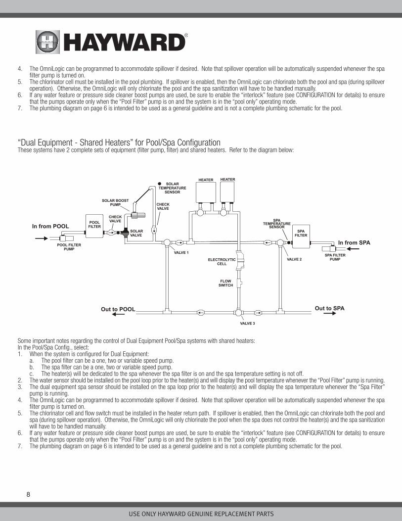
“Dual Equipment - Shared Heaters” for Pool/Spa ConfigurationThese systems have 2 complete sets of equipment (filter pump, filter) and shared heaters. Refer to the diagram below:
Some important notes regarding the control of Dual Equipment Pool/Spa systems with shared heaters:In the Pool/Spa Config., select: 1. When the system is configured for Dual Equipment: a. The pool filter can be a one, two or variable speed pump.
b. The spa filter can be a one, two or variable speed pump. c. The heater(s) will be dedicated to the spa whenever the spa filter is on and the spa temperature setting is not off. 2. The water sensor should be installed on the pool loop prior to the heater(s) and will display the pool temperature whenever the “Pool Filter” pump is running.3. The dual equipment spa sensor should be installed on the spa loop prior to the heater(s) and will display the spa temperature whenever the “Spa Filter”
pump is running.4. The OmniLogic can be programmed to accommodate spillover if desired. Note that spillover operation will be automatically suspended whenever the spa
filter pump is turned on.5. The chlorinator cell and flow switch must be installed in the heater return path. If spillover is enabled, then the OmniLogic can chlorinate both the pool and
spa (during spillover operation). Otherwise, the OmniLogic will only chlorinate the pool when the spa does not control the heater(s) and the spa sanitization will have to be handled manually.
6. If any water feature or pressure side cleaner boost pumps are used, be sure to enable the “interlock” feature (see CONFIGURATION for details) to ensure that the pumps operate only when the “Pool Filter” pump is on and the system is in the “pool only” operating mode.
7. The plumbing diagram on page 6 is intended to be used as a general guideline and is not a complete plumbing schematic for the pool.
POOLFILTER
ELECTROLYTICCELL
FLOWSWITCH
POOL FILTERPUMP
VALVE 1
VALVE 2
VALVE 3
In from POOL
Out to SPAOut to POOL
In from SPA
SPATEMPERATURE
SENSORSPA
FILTER
SPA FILTERPUMP
HEATER HEATER
SOLAR BOOSTPUMP
SOLARVALVE
CHECKVALVE
SOLARTEMPERATURE
SENSOR
CHECKVALVE

USE ONLY HAYWARD GENUINE REPLACEMENT PARTS
9
Optional TurboCellThe TurboCell (used for chlorine generation) must be plumbed AFTER the filter and heater. If installed on a pool/spa combination system, the cell must be plumbed BEFORE the pool/spa return valve in order to allow proper chlorination of both the pool and the spa. Refer to plumbing diagram below:
The cell may be mounted vertically or horizontally, and water can move in either direction through the cell. Install using the 2” unions provided. Tighten unions BY HAND for a watertight seal. For systems with 1½” plumbing use adapters (provided by installer).
Flow Switch (supplied with P-KIT)A Hayward flow switch is required if using the optional TurboCell for chlorination or an AQL-CHEM2 for pH dispensing. The flow switch is a safety device that ensures that water is flowing through the cell before the OmniLogic starts to generate chlorine or dispenses acid.
The flow switch must be plumbed in the same section of plumbing as the TurboCell. Failure to properly install the flow switch can result in explosive gases accumulating in the pool plumbing system.
IMPORTANT: There must be at least a 12” (30cm) straight pipe run before (upstream) the flow switch. If the switch is plumbed after the cell, the cell can be counted as the 12” (30cm) of straight pipe.
IMPORTANT: To ensure proper operation, verify that the arrow on the flow switch points in the direction of water flow.
FLOW
SWITCH
VALVE
POOL
SPA
12”
FLOW
SWITCH
VALVE
TurboCell TurboCell
POOL SPA
12”min
min
Flow Switch
before Cell
Flow Switch
after Cell

USE ONLY HAYWARD GENUINE REPLACEMENT PARTS
10
Electrical Wiring
The OmniLogic requires both high and low voltage connections. Low voltage connections will be made to actuators, sensors, remote keypad, etc. High voltage connections will be made to pumps, lights, etc., as well as providing direct input power to the Control Center. Always:
-Ensure that Power is disconnected prior to performing any wiring-Follow all local and NEC (CEC if applicable) codes-Use copper conductors only-Remove power to the OmniLogic subpanel before removing the deadfront
HLWLAN Power

USE ONLY HAYWARD GENUINE REPLACEMENT PARTS
11
Main Service (Power to the Circuit Breaker Subpanel)The OmniLogic circuit breaker subpanel can accommodate up to 12 circuit breakers and is rated for 125A service. Run properly rated conductors (L1, L2, N, and ground) from the primary house electrical panel to the main power connections on the OmniLogic circuit breaker base. The connection at the main house panel should be to a 240VAC circuit breaker rated at 125A maximum.
Grounding and BondingConnect a ground wire from the primary electrical panel to the OmniLogic ground bus bar. Also ground each piece of high voltage (120 or 240VAC) equipment that is connected to the OmniLogic control relays or circuit breakers. The OmniLogic should also be connected to the pool bonding system by an 8AWG (6AWG for Canada) wire. A lug for bonding is provided on the outside/bottom of the OmniLogic enclosure.
Circuit Breaker Installation and WiringCircuit breakers are to be supplied by the installer. Refer to the circuit breaker chart below for a list of suitable circuit breakers that can be used. Follow the code and the circuit breaker manufacturer’s rating requirements regarding the size and temperature rating for wiring. Note that some pool equipment may be required to be connected to ground fault circuit breakers—check local and NEC (CEC) codes.
General Purpose OutletIf desired, a duplex receptacle with weatherproof cover (supplied by installer) may be installed in the knockout on the lower right side of the OmniLogic enclosure. Per code, use a GFCI type receptacle or a standard receptacle protected by a Ground Fault Circuit Breaker.
OmniLogic PowerThe OmniLogic requires 120VAC, 5A power to operate the control logic circuits and the chlorinator. This power should be connected to a dedicated circuit breaker.
WARNING: 120VAC only (permanent damage will occur if connected to 240V) !

USE ONLY HAYWARD GENUINE REPLACEMENT PARTS
12
USE ONLY HAYWARD GENUINE REPLACEMENT PARTS
Connection TableThe HLBASE includes 4 high voltage relays, 4 low voltage/heater relays, 4 valve outputs and 4 temperature sensor inputs. Additional relays and inputs/outputs can be added using an HLRELAYBANK, HLIOEXPAND or HLRELAY(s) (see Accessories) . When wiring pool equipment to the OmniLogic, keep a record of all connections. You’ll need to record which input/output is used and what equipment is attached. To aid in this process, use the table below. To identify the vari-ous inputs/outputs, refer to the diagram on the side of the table. After attaching a equipment to the OmniLogic, fill in the appropriate information in the table.
HVR5
HVR6
HVR8
HVR7
Connection Table

USE ONLY HAYWARD GENUINE REPLACEMENT PARTS
13
High Voltage WiringHigh Voltage Relays - (120/240V) Pool EquipmentAll OmniLogic relays are double pole (they make/break both “legs” of 240V circuits) and are rated at 3HP/30A at 240V (1½HP/30A at 120V). Refer to the diagram below for typical relay wiring. Record all connections using the table on page 12.
WARNING: Do not use the OmniLogic to control an automatic pool cover. Swimmers may become entrapped underneath the cover.
WARNING: Do not use the OmniLogic to control fire pits or fire features.
Two speed filter pumpRequires two relays for proper operation of both speeds. NOTE: When selecting relays for two speed operation, note that both relays must be within the Relay Bank (HLRELAYBANK) or neither relay should be within the Relay Bank. The diagram below shows the pump connected to relays outside of the Relay Bank.
!
!
USE ONLY HAYWARD GENUINE REPLACEMENT PARTS
14
LightsA ground fault circuit breaker (GFCB) must be used to supply power for high voltage pool/spa lighting. Low voltage lights will require an external transformer. For lighting systems that have both a light source and color wheel, connect the light source to one relay and then connect the color wheel to a different relay.
Universal ColorLogic Lights (UCL): Multiple UCLs must be wired to the same relay if synchronization is desired. Refer to your ColorLogic manual for more information.
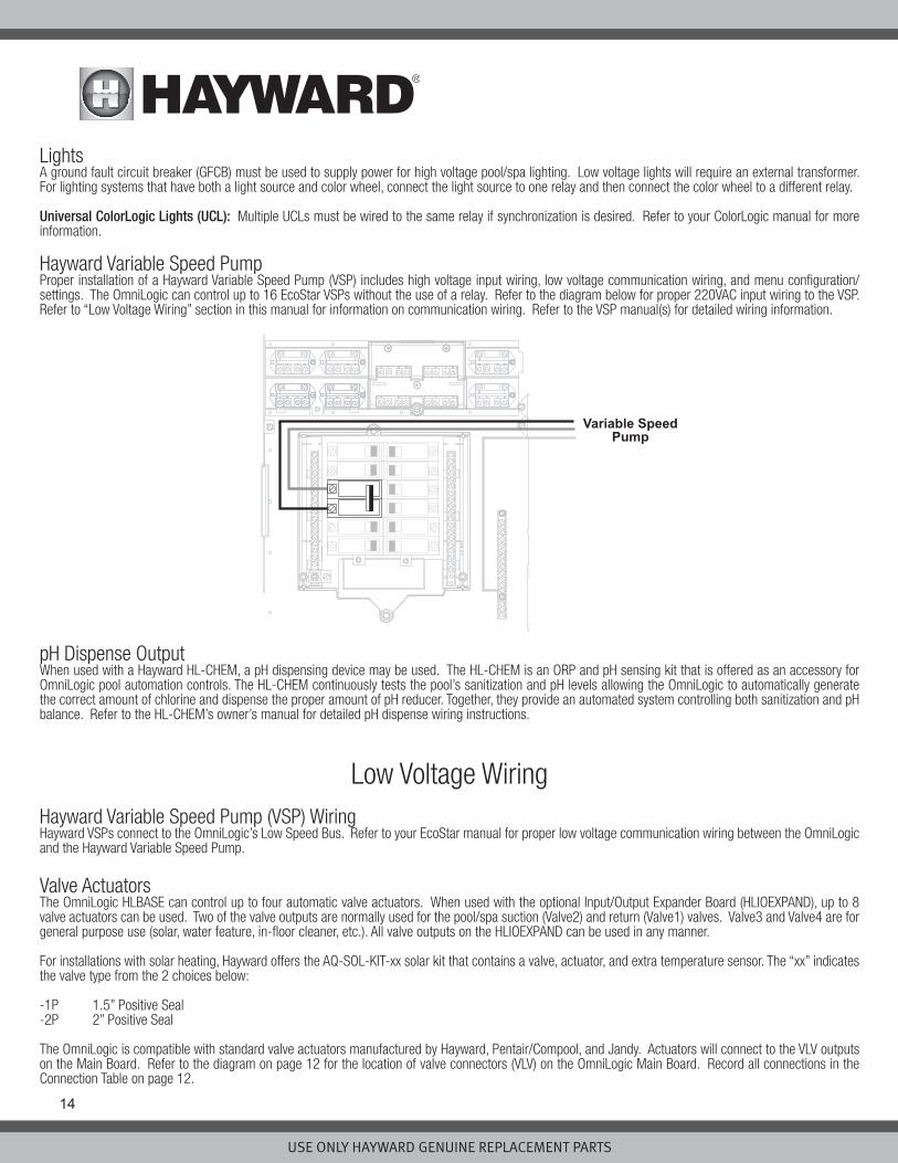
Hayward Variable Speed PumpProper installation of a Hayward Variable Speed Pump (VSP) includes high voltage input wiring, low voltage communication wiring, and menu configuration/settings. The OmniLogic can control up to 16 EcoStar VSPs without the use of a relay. Refer to the diagram below for proper 220VAC input wiring to the VSP. Refer to “Low Voltage Wiring” section in this manual for information on communication wiring. Refer to the VSP manual(s) for detailed wiring information.
pH Dispense OutputWhen used with a Hayward HL-CHEM, a pH dispensing device may be used. The HL-CHEM is an ORP and pH sensing kit that is offered as an accessory for OmniLogic pool automation controls. The HL-CHEM continuously tests the pool’s sanitization and pH levels allowing the OmniLogic to automatically generate the correct amount of chlorine and dispense the proper amount of pH reducer. Together, they provide an automated system controlling both sanitization and pH balance. Refer to the HL-CHEM’s owner’s manual for detailed pH dispense wiring instructions.
Low Voltage WiringHayward Variable Speed Pump (VSP) WiringHayward VSPs connect to the OmniLogic’s Low Speed Bus. Refer to your EcoStar manual for proper low voltage communication wiring between the OmniLogic and the Hayward Variable Speed Pump.
Valve ActuatorsThe OmniLogic HLBASE can control up to four automatic valve actuators. When used with the optional Input/Output Expander Board (HLIOEXPAND), up to 8 valve actuators can be used. Two of the valve outputs are normally used for the pool/spa suction (Valve2) and return (Valve1) valves. Valve3 and Valve4 are for general purpose use (solar, water feature, in-floor cleaner, etc.). All valve outputs on the HLIOEXPAND can be used in any manner.
For installations with solar heating, Hayward offers the AQ-SOL-KIT-xx solar kit that contains a valve, actuator, and extra temperature sensor. The “xx” indicates the valve type from the 2 choices below:
-1P 1.5” Positive Seal-2P 2” Positive Seal
The OmniLogic is compatible with standard valve actuators manufactured by Hayward, Pentair/Compool, and Jandy. Actuators will connect to the VLV outputs on the Main Board. Refer to the diagram on page 12 for the location of valve connectors (VLV) on the OmniLogic Main Board. Record all connections in the Connection Table on page 12.

USE ONLY HAYWARD GENUINE REPLACEMENT PARTS
15
Heater ControlThe HLBASE OmniLogic provides a set of 4 low voltage dry contacts that can be connected to most gas heaters or heat pumps with 24V control circuits. When used with the optional Input/Output Expander Board (HLIOEXPAND), 8 dry contact relays are available. Refer to the diagram below for a generic heater con-nection. The manuals supplied with most heaters also include specific wiring instructions for connecting the heater to an external control (usually identified as “2-wire” remote control). For millivolt or line voltage heaters, contact Hayward Tech support, 908-355-7995. Refer to the information on the following pages for more details on the connection to several popular heaters. Refer to the diagram on page 12 for the location of heater connections (LVR) on the OmniLogic Main Board. Record all connections in the Connection Table.
Generic Heaters1. Wire heater to 120/240V power source per the instructions in the heater manual. The OmniLogic does NOT control the power going to the heater.2. Wire the OmniLogic dry contact heater output per the diagram below. Many internal parts of the heater can get very hot--see the heater manufacturer’s
recommendations on the minimum temperature rating for wires. If no guidance is given, use 105°C rated wire.3. Set any ON/OFF switch on the heater to ON.4. Set the thermostat(s) on the heater to the maximum (hottest) setting.
Laars Heaters 1. Turn power off to heater.2. Remove factory jumper from terminal block.3. Wire OmniLogic to the heater as shown.4. Ensure toggle switch is in the ON position.5. Set heater thermostats to maximum position.

USE ONLY HAYWARD GENUINE REPLACEMENT PARTS
16
Hayward Pre-2007 HeatersRefer to the instructions in the heater manual for “2-wire Remote Thermostat” operation under “Remote Control Connections” and the diagram below:1. Turn off power to heater. 2. Wire OmniLogic to terminals 1 & 2 (see diagram). 3. Leave jumper attached to terminals 4 & 5. 4. Move “BYPASS” dipswitch on heater circuit board to “ON” position (up). 5. Turn heater power back on. 6. Switch heater to either “Pool” or “Spa” (it doesn’t make any difference which is selected, the OmniLogic will take control). 7. Heater display should be “bO” (for “bypass On). 8. Heater will start whenever OmniLogic requests (when OmniLogic “Heater” LED is illuminated).
Hayward 2007-Current HeatersRefer to the instructions in the heater manual for “2-wire Remote Thermostat” operation under “Remote Control Connections” and the diagram below: 1. Turn off power to heater. 2. Wire OmniLogic to the heater terminals that have the Orange & White connections (see diagram). 3. Turn heater power back on. 4. Use the “MODE” key on the heater keypad to put the control into “STANDBY” mode.5. Press and hold both the “DOWN” and “MODE” keys for 3 seconds until the display shows the code “bo”.6. Be sure to put the heater’s control in either “POOL” or “SPA” mode.7. The OmniLogic will now control the heater.

USE ONLY HAYWARD GENUINE REPLACEMENT PARTS
17
Pentair/Purex/MiniMax1. Turn power off to heater.2. Remove factory installed jumper from the “Ext Switch” connector.3. Wire OmniLogic to the “Ext Switch” connector as shown below.4. The wires to the OmniLogic must be separated from any line voltage wires. Failure to follow these instructions may cause erratic operation of the heater.5. Set the Power (Thermostat Select) switch to either “Pool” or “Spa”.6. Set the “Pool” and “Spa” thermostats to their maximum settings.
Raypak RP2100 Pool/Spa Heater1. Turn power off to heater. 2. Push the mode button to “spa” mode.3. Set the temperature to the maximum.4. Push the mode button to “OFF”.5. Lastly, plug the prewired connector in the P7 position on the board.
IMPORTANT: The heater will display “OFF” when it is being remotely controlled by the OmniLogic. Some homeowners see the “OFF” display and, thinking this is a mistake, change the mode to “POOL” or “SPA” which then disables the remote control by the OmniLogic. To prevent this: Remove the heater touch pad connector (P5) which will disable the touchpad.

USE ONLY HAYWARD GENUINE REPLACEMENT PARTS
18
STA-RITE Heater1. Turn power off to heater.2. Remove upper jacket and open the control box.3. Remove the jumper for the “fireman’s switch.4. Wire to the OmniLogic using wire rated for 105°C minimum.
Temperature SensorsThe OmniLogic utilizes 10K ohm thermistor type sensors and provides three inputs. Three sensors (water temperature, air temperature and solar or dual equip-ment spa temperature) are included. If the OmniLogic is being used to control a solar heating system, the solar sensor is required. If dual equipment will be used, the dual equipment spa sensor is required. If both solar and dual equipment are desired, another temperature sensor must be purchased separately. The sensors are provided with a 15 ft. cable. If a longer cable is required, contact the Hayward service dept. (908-355-7995) for information on suitable cable types and splices. Wire sensors as shown below. Record all connections using the table on page 12.
External Input InterlockThe External Input Interlock provides a means to turn the filter pump or other component on/off when certain conditions exists. A normally open or normally closed on/off external device must be connected to the OmniLogic as shown below. After properly configuring the OmniLogic (see Configuration Wizard in Operation Manual), the filter pump and/or desired pool component will be forced on or off when the device is active. Record all connections using the table on page 12.

USE ONLY HAYWARD GENUINE REPLACEMENT PARTS
19
Remote TerminalUp to 2 wired HLWALLMOUNT touchscreen remote terminals can be wired to the OmniLogic. Use 24 AWG (or better) four conductor cable (typically phone cable) to connect the wired remote terminal to the OmniLogic’s High Speed Bus as shown below. Note that the screw connections on both the OmniLogic main unit and the wired remote terminal are numbered: Connect 1 to 1, 2 to 2, etc. as shown in the diagram below. Although the High Speed Bus has 5 screw terminals, screw #5 is not used. Refer to the HLWALLMOUNT manual for maximum distances and complete installation instructions.
HL-CHEM ORP and pH Sensing KitPlug in the connector from the HL-CHEM into one of the Low Speed Bus connectors on the main PCB in the OmniLogic Control Center as shown below. Refer to the HL-CHEM manual for complete installation instructions.
Remote Terminal
Refer to HLWALLMOUNTmanual for max distance
1234
OmniLogicMain Board
1234
Connect screw terminals“1” to “1”, “2” to “2”, etc.
x
Connect Probe Cell cable here
Route cablethroughaccess hole
Routethoughknockout

USE ONLY HAYWARD GENUINE REPLACEMENT PARTS
20
Home RouterConnection to the web is optional. If web enabled devices such as a PC, laptop, tablet or phone will be used to access the OmniLogic, an ethernet connection must be made to the home router. Use outdoor rated Cat5e or Cat6 ethernet cable and run a loop through the supplied ferrite bead as shown in the diagram. Connect one end to the OmniLogic and the other to an available LAN port (not WAN) on the home router.
Flow SwitchOnly applicable if the chlorinator function is enabled and/or if an optional HL-CHEM will be used. The flow switch cable plugs into the flow switch connector on the OmniLogic’s Main Board as shown on page 10. Ensure that the connector catch “snaps” in order to provide a reliable connection.
TurboCellOnly applicable if the chlorinator function is enabled. The TurboCell should be plugged in AFTER the OmniLogic cover panel is installed. Refer to page 10 for the location of the chlorinator cell connector. HLIOEXPANDThe HLIOEXPAND is design to slide between guide rails and insert into a dedicated slot on the OmniLogic main board. At startup, the OmniLogic will discover the HLIOEXPAND and its inputs/outputs can be configured within the OmniLogic’s CONFIGURATION WIZARD. Refer to the HLIOEXPANDER manual for installa-tion instructions.
HLRELAYBANKOffering four additional high voltage relays, the HLRELAYBANK is a relay kit accessory designed to install next to the four on-board relays in the HLBASE. After installing the HLRELAYBANK, a wire connection must be made at the OmniLogic Main Board. At startup, the OmniLogic will detect the HLRELAYBANK and allow the user to configure the additional relays in the CONFIGURATION WIZARD. Refer to the HLRELAYBANK manual for installation instructions.
HLRELAYThe HLRELAY is a single high voltage relay designed to be mounted in the #9 and/or #10 positions near the four on-board relays. After installing the HLRELAY, a wire connection must be made at the OmniLogic Main Board. At startup, the OmniLogic will detect the HLRELAY and allow the user to configure the additional relay(s) in the CONFIGURATION WIZARD. Refer to the HLRELAY manual for installation instructions.
HLWLANThe HLWLAN can be mounted up to 25ft away from the OmniLogic and requires an ethernet connection to the OmniLogic as well as a power connection to the OmniLogic’s Main Board. Refer to the HLWLAN manual for detailed installation instructions.
ethernet port
Loop ethernet cablethrough the ferrite beadthat is included with the OmniLogic
Router
LAN port
USE ONLY HAYWARD GENUINE REPLACEMENT PARTS
21
Preparing Pool/Spa WaterChlorinationWhen used with an optional Hayward TurboCell and P-KIT, the OmniLogic can generate all the chlorine needs for pools up to 40,000 gallons (150,000 liters), or the needs of most commercial pools up to 25,000 gallons (95,000 liters). If enabled (see Configuration Wizard), this operation requires a low concentration of salt (sodium chloride) in the pool/spa water. The OmniLogic automatically converts salt into free chlorine which kills bacteria and algae in the pool/spa. Chlorine will revert back to sodium chloride after killing bacteria. These reactions will continuously recycle, virtually eliminating the need to add sanitizing chemicals to your pool/spa. The only time you may need to add more salt to the pool/spa is when water is replenished due to backwashing, draining, or splashing (not evaporation). The actual amount of chlorination required to properly sanitize a pool varies due to bather load, rainfall, temperature, and the pool’s cleanliness.
General Water ChemistrySalt is required only if you are using the chlorinator features on the OmniLogic Control Center. If you are NOT using the chlorinator, it is recommended that you follow all of the other chemistry recommendations besides salt.
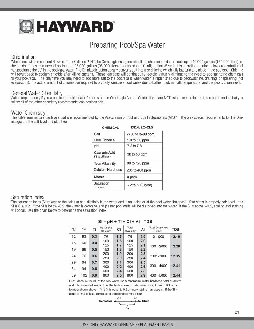
Water ChemistryThis table summarizes the levels that are recommended by the Association of Pool and Spa Professionals (APSP). The only special requirements for the Om-niLogic are the salt level and stabilizer.
Saturation indexThe saturation index (Si) relates to the calcium and alkalinity in the water and is an indicator of the pool water “balance”. Your water is properly balanced if the Si is 0 ± 0.2. If the Si is below -0.2, the water is corrosive and plaster pool walls will be dissolved into the water. If the Si is above +0.2, scaling and staining will occur. Use the chart below to determine the saturation index.
Si = pH + Ti + Ci + Ai - TDSHardnessCalcium
75100125150200250300400600800
Total DissolvedSolids
Totalalkalinity°C °F Ti Ci Ai TDS
12
16
19
24
29
34
39
53
60
66
76
84
94
102
0.3
0.4
0.5
0.6
0.7
0.8
0.9
1.51.61.71.81.92.02.12.22.42.5
75100125150200250300400600800
1.92.02.12.22.32.42.52.62.82.9
0-1000
1001-2000
2001-3000
3001-4000
4001-5000
12.10
12.29
12.35
12.41
12.44Use: Measure the pH of the pool water, the temperature, water hardness, total alkalinity, and total dissolved solids. Use the table above to determine Ti, Ci, Ai, and TDS in the formula shown above. If the Si is equal to 0.2 or more, stains may appear. If the Si is equal to -0.2 or less, corrosion or deterioration may occur.
Corrosion Stain
Ok
-0.2 0.2

USE ONLY HAYWARD GENUINE REPLACEMENT PARTS
22
The pool’s chemistry must be balanced BEFORE activating the OmniLogic’s optional chlorinator function. NOTE: If the pool does not have new water, add metal remover and non-copper based algaecide to the pool, per manufacturer’s instructions. This ensures a quick, troublefree transfer to the OmniLogic system.
Salt (When using optional chlorinator function)Use the chart on the following page to determine how much salt in pounds or (Kgs) should be added to reach the recommended levels. Use the Pool Sizing Formula below (measurements are in feet/gallons and meters/liters) if pool size is unknown.
The operating salt level is between 2700-3400 PPM (parts per million) with 3200 PPM being optimal. Before adding any salt, test the salt level. This is espe-cially important for retrofit installation to older pools where all of the chlorine added to the pool over time is ending up as salt. If the level is low, determine the number of gallons in the pool and add salt according to the chart below. A low salt level will reduce the efficiency of the sanitization and result in low chlorine production. A high salt level can cause the OmniLogic to stop chlorinating. The salt in your pool/spa is constantly recycled and the loss of salt throughout the swimming season should be minimal. This loss is due primarily to the addition of water because of splashing, backwashing, or draining (because of rain). Salt is not lost due to evaporation.

USE ONLY HAYWARD GENUINE REPLACEMENT PARTS
23
Type of Salt to UseIt is important to use only sodium chloride (NaCl) salt that is greater than 99.0% pure. This can be found at most pool stores in 40-80 lb. bags labeled “for use in swimming pools”. Alternatively, use common food quality or water softener salt that is at least 99.0% pure. It is also acceptable to use water conditioning salt pellets, however, it will take longer for them to dissolve. Do not use rock salt, or salt with more than 1% of yellow prussiate of soda, salt with anti-caking additives, or iodized salt.
How to Add SaltFor new plaster pools, wait 10-14 days before adding salt to allow the plaster to cure. Turn the circulating pump on and add salt directly into the pool. Brush the salt around to speed up the dissolving process—do not allow salt to pile up on the bottom of the pool. Run the filter pump for 24 hours with the suction coming from the main drain (use pool vacuum if there is no main drain) to allow the salt to evenly disperse throughout the pool. The salt display may take 24 hours to respond to the change in salt concentration.
Always check stabilizer (cyanuric acid), when checking salt. These levels will most likely decline together. Use the chart below to determine how much stabilizer must be added to raise the level to 40 ppm.
System StartupBefore StartupBefore starting the OmniLogic for the first time, be sure that the following items have been completed:
1. Pool/spa chemicals are within the recommended levels according to the chart on page 21.2. If using chlorinator function, pool/spa salt level is between 2700 – 3400 PPM.3. Properly rated circuit breakers are installed in the OmniLogic subpanel.4. All wiring is performed according to NEC and local codes.5. The OmniLogic is properly grounded and bonded.
Firmware UpgradeThe OmniLogic’s firmware is the basic operating system that runs the unit. The OmniLogic was shipped with the version of firmware that was available at the time of release. There may be a newer version available and if so, we encourage you to upgrade. Also, if you have experienced problems, Hayward Technical Support may advise you to upgrade your OmniLogic firmware. To upgrade the OmniLogic firmware, refer to the procedure shown in the OmniLogic Operation Manual. Upgrading firmware can be performed before or after Configuration but should be done before the OmniLogic begins operation.

USE ONLY HAYWARD GENUINE REPLACEMENT PARTS
24
ConfigurationInitial ConfigurationWhen all input and pool related wiring is complete, replace and secure the deadfront. The OmniLogic can now be powered on for the first time. Apply power at the main panel and wait for the OmniLogic to completely start. This may take a full minute or two. Because this is the first time that the OmniLogic has been powered on, it will bring you directly to the initial configuration screen shown below. Note that the OmniLogic uses a resistive touchscreen that is appropriate for a pool environment. It requires a deliberate push when selecting a button. At the initial configuration screen, touch the Configuration button in the center of the screen. On the following screen, touch the Configuration Wizard button as shown below.
About the Configuration WizardThe OmniLogic uses a Configuration Wizard to assist in the configuration of the OmniLogic. The Configuration Wizard will ask you general questions relating to your pool/spa and specific questions about connected pool equipment. Because this process may take some time, do not begin to configure the OmniLogic unless you can dedicate at least 15 minutes or more. Configuring the OmniLogic requires knowledge of all of the connected pool equipment so have the Con-nection Table (page 12) handy while configuring the OmniLogic.
If you are asked a question and don’t know the answer, in many cases you’ll be able to skip the question and proceed. In some cases the Configuration Wizard will require an answer. Answer the question to the best of your ability and take note as you’ll be able to go back into the Configuration Wizard at a later time to make changes.
NavigationThe Configuration Wizard has been designed to be intuitive allowing most users the ability to navigate with little instruction. Below, a list of commonly used buttons are explained..
Done - Touch this button to complete your selection.
Cancel - Touch this button to cancel your selection.
Advance - Touch this button to advance to the next screen.
Back - Touch this button to return to the previous screen.
Add - Touch this button to add an item
Delete - Touch this button to delete a highlighted item.
After being prompted to make a selection or answer a question, touch the Done button (if available) and then the Advance button to go to the next screen. To go back to a previous screen, touch the Back button. Many selections will require you to touch the Done button before allowing you to advance. If a wrong selection has been made, touch the Delete button or Cancel. Some settings can be made by sliding a bar left or right to decrease or increase a value. You may be required to assign names to equipment. In this case, a keyboard will be displayed and you’ll be able to type the desired name. After naming the equipment, save then advance. This method is repeated throughout the Configuration Wizard.
configuration
No con�g found
SYSTEMcon�guration
1 / 2
system info
con�g wizard
backup con�g
restore con�g
display
network
web server
date/time

USE ONLY HAYWARD GENUINE REPLACEMENT PARTS
25
Begin the Configuration WizardIn the Configuration Wizard, select “New” to create a new Configuration file for the OmniLogic. Once underway, keep advancing until you have completed the Wizard. At the end of the Wizard, you’ll have the opportunity to save your settings or exit without saving.
BACKYARDcon�guration
Yes
No
Are you �nished con�guring your system?
At the end of the Wizard, save your configuration by answer-ing “Yes” to this screen.
BACKYARDcon�guration
New
Edit
Create a New Con�gurationor Edit an Existing One?
If additional pool or backyard equipment is added after initial configuration, or you’d like to make a change to an existing configuration setting, re-enter the Configuration Wizard and select “Edit”. The initial configuration settings will be retained and you’ll have an opportunity to make changes or additions. Be sure to save your configuration when exiting. See page 37 for a Quick Edit Guide.
Configuration Wizard GuideAs you progress through the Configuration Wizard, refer to the following information to help answer questions and make selections.
Select a Language - The OmniLogic will support multiple languages. Select the desired language then touch the Advance button to advance.
Time and Date - Set the current date and time using a 12hr clock (AM/PM) or 24hr clock (military time). Save by touching the Done button when finished. NOTE: When registering the OmniLogic and creating a web account, you’ll be prompted to enter a Time Zone. Be sure to enter the same time zone as the physical location of the OmniLogic, otherwise schedules and timers will be inaccurate.
Select Desired Units of Measure - If Standard is selected, temperatures will be displayed in Fahrenheit. If Metric is selected, temperatures will be displayed in Celsius.
MSP ID - The OmniLogic MSP ID number will be displayed. This unique number is used to identify your OmniLogic when setting up a web account. A web account is needed to access the OmniLogic over the web by mobile devices. IMPORTANT: write down the MSP ID number for future use. The MSP ID number will be needed when entering the configuration wizard after initial configuration as well as entering and exiting Simple Mode. Simple Mode is a customizable screen that can be set up for quick access to pool/spa functions and features.
How many Bodies of Water? The OmniLogic can support one or two bodies of water, typically a pool and spa. Select the number and advance. You’ll be brought to a screen where you can add, delete or edit a Body of Water. When initially configuring the OmniLogic, a “?” will appear in the Body of Water button. You will have to configure this body of water by selecting it and then touching the Advance button. When finished configuring bodies of water, you’ll be returned to this same screen. Touch the Done button and advance to the next section of configuration.
IMPORTANT: The following instructions are for Body of Water 1 configuration. When finished with the first Body of Water, you’ll follow the same instructions for the second Body of Water. When configuring the second Body of Water, you’ll have the option of using “Shared Equipment”. If Shared Equipment is enabled, the second Body of Water will use the filter pump as well as other equipment (heater, chlorinator, etc.) that has been assigned to the first Body of Water. Additionally, you will have the option for using “Shared Heaters”. If you have dual equipment with shared heaters, this can be configured from the second Body of Water’s configuration menu. See page 33 for more information regarding Shared Equipment in the second Body of Water configuration menu.
What is the Body of Water type? Select the type of Body of Water that you would like to configure. The choices are Pool and Spa.
Name of Body of Water - Selecting the box will allow you to edit the name. During initial configuration, the box will be blank. Select the box and then use the keyboard to enter the desired name of the body of water.
Size of Body of Water - Enter the Body of Water size in gallons. If you’re not certain the size of your pool, refer to the chart on the following page to help determine the pool capacity.
USE ONLY HAYWARD GENUINE REPLACEMENT PARTS
26
How Many Filter Pumps? - This question is for THIS BODY OF WATER ONLY. For example: If you have 2 pumps; one for the pool Body of Water and one for the spa Body of Water, you would answer “1” to this question.
If “1”or more is selected:Name Filter Pump - Touch the box and use the keyboard to name the filter pump.
What Type - Depending on your answer, the OmniLogic will use one relay (single speed pumps), two relays (two speed pumps) or the low speed communication bus (VSP pumps) for pump control. Select the type of pump and advance.
If one speed or two speed pump is selected: Which Relay is it Wired to? If using a single speed or two speed pump, you’ll be asked which relay(s) is wired to the pump. If a value is already shown in the box(es), advance to the next screen. If no value is shown, selecting the box will bring you to a table showing all detected relays. Select the proper relay(s) from the table and touch the Done button to proceed. The relay(s) should now be shown in the box(es) and you can advance to the next screen to continue the pump configuration.
Filter Pump Off for Valve Change? When Yes is selected, the pump will shut off for 35 seconds whenever the valve(s) change posi-tion.
Flow Monitoring Enabled? Requires use of a Hayward flow switch. This feature will help protect the filter pump from damage due to no flow. When Yes is selected, the OmniLogic will monitor the state of water flow when the filter pump is on. If no flow is detected for more than 20 minutes, the OmniLogic will shut down the pool pump and will indicate an error. The error will be cleared the next time the pump is turned on.
Would You Like to Enable Priming? Select whether you want the filter pump to prime when turned on. This will turn the pump on at high speed for 3 minutes to establish normal water flow every time the pump is activated after being off for at least 30 seconds. This option only appears if the filter pump is configured as a 2-Speed pump.
Freeze Protection Enabled? Freeze protection is used to protect the pool and plumbed equipment against freeze damage during cold temperatures. If freeze protection is enabled AND the air temperature falls below the freeze threshold, the OmniLogic will turn on the filter pump to circulate the water. If two Bodies of Water are configured, the valves will also alternate between the pool and spa every 30 minutes and the filter pump will turn off while the valves are turning. The chlorinator will not operate if freeze protection is the only reason the pump is running.
If Yes is selected: Freeze Protection Temperature? Select the temperature to be used for freeze protection. Temperature is adjustable from 33ºF-42ºF (1ºC-6ºC). 38ºF (3ºC) is default. This threshold will be used for all outputs that have freeze protection enabled.
If VSP is selected: Which Hayward Unique Address? If using a VSP, you’ll be asked what is the Hayward Unique Address (HUA). If a value is already shown in the box, advance to the next screen. If no value is shown, selecting the box will bring you to a table showing all detected devices. Select the proper HUA from the table and touch the Done button. If unsure of the HUA, refer to the pump’s manual for instruc-tions on how to determine the pump’s HUA. Once selected, the address should now be shown in the box and you can advance to the next screen to continue the VSP configuration.
Pump Capacity - Set the minimum and maximum RPM of the pump. Refer to your pump manual for more information.
Permitted User Setting - The OmniLogic will automatically calculate these values based on the minimum and maximum RPM that were previously entered. They can be changed as desired. Speed Presets - Set the Low Pump Speed %, Medium Pump Speed %, and High Pump Speed %, presets. These presets will be used when setting schedules for your pump.
Filter Pump Off for Valve Change? When Yes is selected, the pump will shut off for 35 seconds whenever the valve(s) change posi-tion.
Flow Monitoring Enabled? Requires use of a Hayward flow switch. This feature will help protect the filter pump from damage due to no flow. When Yes is selected, the OmniLogic will monitor the state of water flow when the filter pump is on. If no flow is detected for more than 15 minutes, the OmniLogic will shut down the pool pump and will indicate an error. The error will be cleared the next time the pump is turned on.
Would You Like to Enable Priming? Select whether you want the filter pump to prime when turned on. This will turn the pump on at high speed for 3 minutes to establish normal water flow every time the pump is activated after being off for at least 30 seconds.
Freeze Protection Enabled? Freeze protection is used to protect the pool and plumbed equipment against freeze damage during cold temperatures. If freeze protection is enabled AND the air temperature falls below the freeze threshold, the OmniLogic will turn

USE ONLY HAYWARD GENUINE REPLACEMENT PARTS
27
on the filter pump to circulate the water. If two Bodies of Water are configured, the valves will also alternate between the pool and spa every 30 minutes and the filter pump will turn off while the valves are turning. The chlorinator will not operate if freeze protection is the only reason the pump is running.
If Yes is selected: Freeze Protect Temperature? Select the temperature to be used for freeze protection. Temperature is adjustable from 33ºF-42ºF (1ºC-6ºC). 38ºF (3ºC) is default. This threshold will be used for all outputs that have freeze protection enabled.
Freeze Protect Speed? This is the speed of the pump while freeze protection is active. Select the desired pump speed %.
How many Heaters? This question is for THIS BODY OF WATER ONLY. For example: If you have 2 heaters, one for the pool Body of Water and one for the spa Body of Water, you would answer “1” to this question.
If “1”or more is selected:Heater Cooldown Enabled? This feature ensures that the heater cools down before water circulation is stopped. When enabled, the Omni-Logic will continue to run the filter pump for 5 minutes after the heater turns off.
Heater Extend Enabled? If “Enabled”, the filter extend logic keeps the filter pump running beyond the normal turn-off time until the pool (or spa) is heated up to the desired temperature setting. Heater extend will NOT cause the filter pump to turn on, it will only delay the turn off time when the heater is operating. Maximum Settable Temperature? This is the maximum allowed setting for the heater regardless of its default range. There may be circum-stances where you will want to limit the high temperature of your heater to a temperature that is lower than the factory high setting.
Select and Configure a Heater At this screen, you can add, delete and configure your heater(s). Select the desired heater, then touch the Advance button. When finished configuring heater(s), you’ll be returned to this same screen. Touch the Done button and advance to the next section of configuration. Refer to the following information when configuring heater(s):
What Type? Heater choices are Solar, Heat Pump and Gas. Make your selection and advance. If Gas Heater is selected:
Name Heater Select the box, then type the desired name for your heater. This name will be used when referring to this particular heater.
Which Relay is it Wired to? Selecting the box will bring you to a table showing all detected relays. Select the low voltage relay that is wired to the heater (refer to the Connection Table for this information), then advance. The relay should now be shown in the box. Advance to the next screen to continue gas heater configuration.
If more than one heater has been configured for this Body of Water:Heater Priority Level? Because more than one heater is configured to heat this Body of Water, you can set the Priority for which heater you’d like to use first (selection “1”). If the priority heater can’t meet the demand, the next heater will start (selection “2”).
Heater Priority Duration? Set the amount of time that you will allow the priority heater (“1”) to heat before allowing the next heater to start. If the priority heater meets the demand within this time frame, the next heater will not be used. Note that a time interval setting of “0” will eliminate priority and always run both heaters at the same time.
Minimum Operation Speed? For variable speed pumps, select the lowest pump speed that is allowed while heating. Set a speed that will ensure that there will be sufficient flow for the heater to operate properly.
If Heat Pump is selected:
Name Heater Select the box, then type the desired name for your heater. This name will be used when referring to this particular heater.
Which Relay is it Wired to? Selecting the box will bring you to a table showing all detected relays. Select the low voltage relay that is wired to the heater (refer to the Connection Table for this information), then advance. The relay should now be shown in the box. Advance to the next screen to continue heat pump configuration.
Minimum Allowed Air Temperature for Heater? If the air temperature falls below this setting, the heater will be prevented from running, regardless of conditions. This feature is especially useful for heat pumps which become less efficient as the outdoor ambient temperature falls.
If more than one heater has been configured for this Body of Water:Heater Priority Level? Because more than one heater is configured to heat this Body of Water, you can set the Priority for which heater you’d like to use first (selection “1”). If the priority heater can’t meet the demand, the next heater will start (selection “2”).
USE ONLY HAYWARD GENUINE REPLACEMENT PARTS
28
Heater Priority Duration? Set the amount of time that you will allow the priority heater (“1”) to heat before allowing the next heater to start. If the priority heater meets the demand within this time frame, the next heater will not be used.
Minimum Operation Speed? For variable speed pumps, select the lowest pump speed that is allowed while heating. Set a speed that will ensure that there will be sufficient flow for the heater to operate properly.
If Solar is selected: Name Heater Select the box, then type the desired name for your heater. This name will be used when referring to this particular heater.
Does the Solar Heater Have a Pump? Select whether the solar heating system has a dedicated recirculation pump. If so, the OmniLogic will turn this pump on when the pool temperature is below the heater setting and there is solar heat available.
If Yes is selected: Which Relay is it Wired to? Selecting the box will bring you to a table showing all detected relays. Select the high voltage relay that is wired to the heater (refer to the Connection Table in for this information), then advance. The relay should now be shown in the box. Advance to the next screen to continue solar heater configuration.
Does the Solar Heater Have a Valve? Select whether the solar heating system has a diverter valve to route pool/spa water through the solar collectors. If so, the OmniLogic will rotate this valve when the pool temperature is below the heater setting and there is solar heat available.
If Yes is selected: Where is the valve wired? Selecting the box will bring you to a table showing all detected low voltage relays. Select the relay that is wired to the solar valve, then advance. The relay should now be shown in the box. Advance to the next screen to continue solar heater configuration.
Where is the Solar Temperature Sensor Located? Selecting the box will bring you to a table showing all detected sensors. Select the solar sensor (usually SENS3), then advance. The sensor should now be shown in the box. Advance to the next screen to continue solar heater configuration.
If more than one heater has been configured for this Body of Water:Heater Priority Level? Because more than one heater is configured to heat this Body of Water, you can set the Priority for which heater you’d like to use first (selection “1”). If the priority heater can’t meet the demand, the next heater will start (selection “2”).
Heater Priority Duration? Set the amount of time that you will allow the priority heater (“1”) to heat before allowing the next heater to start. If the priority heater meets the demand within this time frame, the next heater will not be used.
Minimum Operation Speed? Select the lowest pump speed that is allowed while solar heating. Set a speed that will ensure that there will be sufficient flow for the solar heating system to operate properly.
Do you have a Sense & Dispense Module? Select Yes if a Hayward HL-CHEM (sold separately) is connected to the OmniLogic. If Yes is selected:
The next few screens will configure the OmniLogic to use Sense and Dispense. The OmniLogic automatically detects smart components like the HL-CHEM, and assigns a Hayward Unique Address. If multiple components are detected, the OmniLogic will show a table of devices and prompt you to select the proper device.
Which Hayward Unique Address? If a Hayward Unique Address (HUA) is already shown in the box, touch the Advance button. If no address is shown, selecting the box will bring you to a table showing all detected Sense and Dispense devices. Select the HL-CHEM from the table and touch the Done button to advance. The address should now be shown. Touch the Advance button to continue configuring the OmniLogic for use with the HL-CHEM.
Does ORP Control Chlorination? If you say Yes to this, the HL-CHEM will constantly measure ORP and will increase or decrease chlorine generation based on a predetermined setpoint that you will select. The system will monitor ORP and automatically generate the correct amount of chlorine to maintain a desired level. Alternatively, if you say No to this question, the HL-CHEM will monitor ORP, but the amount of chlorine generated will be based on a manual setting that you will select.
If Yes is selected: ORP Setpoint - Set the desired ORP level which is measured in mV. 650mV is the default. The OmniLogic will continuously measure ORP and generate the proper amount of chlorine to maintain this setpoint.
ORP Timeout - Select a timeout interval. If the OmniLogic has been chlorinating for more than the selected ORP timeout without reaching the desired level, the chlorinator will turn off and display an alarm. The user must clear the alarm to resume chlorination.

USE ONLY HAYWARD GENUINE REPLACEMENT PARTS
29
Type of Cell? Select the type of Hayward TurboCell that is installed in your system.
Where is the Cell Located? If an entry is already shown in the box, touch the Advance button. If no entry is shown, selecting the box will bring you to a table showing the detected cell. Select the TurboCell and select Done.
If No is selected: Do You Have a Salt Water Chlorine Generator? (requires Hayward Turbo Cell)
If Yes is selected: Type of Cell? Select the type of Hayward TurboCell that is installed in your system.
Where is the Cell Located? If an entry is already shown in the box, touch the Advance button. If no entry is shown, select-ing the box will bring you to a table showing the detected cell. Select the TurboCell select Done.
Percentage of Output - The OmniLogic can only generate chlorine while the filter pump is operating. Set the percentage of run time that you desire chlorine generation. Raise this value to generate more chlorine. Lower this value to generate less.
Is pH Reduction Enabled? Select Yes if you have a dispenser to lower pH connected to the OmniLogic.
If Yes is selected:Are you Using Acid or CO2? Select one.
How Many Acid/CO2 Dispensers? Select the number of Acid/CO2 dispensers in your system.
Which relay is it Wired to? Select the box to advance to the High Voltage Table. This table lists all of the high voltage relays that are installed in the OmniLogic. Select the relay that is wired to the pH dispense unit. Refer to the Connection Table for this information.
pH Setpoint - Selecting the box will allow you to change the setpoint (7.5 default). Touch the Advance button when finished.
pH Dispensing Timeout - Select a timeout interval. If the unit has been dispensing for more than the selected timeout without reach-ing the desired level, pH dispensing will turn off and an alarm will be displayed. Check the chemical supply and the feeder. If both are OK, the timeout may need to be increased. The user must clear the alarm to resume pH dispensing.
pH Extend Enabled - If enabled, the OmniLogic will continue to run the filter pump regardless of schedule until the pH level in the pool has reached the setpoint.
Do You Have a Salt Water Chlorine Generator? (requires Hayward Turbo Cell) If Yes is selected:
Type of Cell? Select the type of Hayward TurboCell that is installed in your system.
Where is the Cell Located? If an entry is already shown in the box, touch the Advance button. If no entry is shown, selecting the box will bring you to a table showing the detected cell. Select the TurboCell and select Done.
Percentage of Output - The OmniLogic can only generate chlorine while the filter pump is operating. Set the percentage of run time that you desire chlorine generation. Raise this value to generate more chlorine. Lower this value to generate less.
How Many Cleaners? - This question is for THIS BODY OF WATER ONLY. For example: If you have 2 cleaners; one for the pool Body of Water and one for the spa Body of Water, you would answer “1” to this question.
If “1”or more is selected:Select and Configure a Cleaner At this screen you can add, delete and configure your cleaner(s). Select the desired cleaner, then touch the Advance button. When finished configuring cleaner(s), you’ll be returned to this same screen. Touch the Done button to advance to the next section of configuration. Refer to the following information when configuring cleaner(s):
Type of Cleaner? Touch the box and select the type of cleaner used. Choices are Pressure, Suction, Robotic and In-Floor.
Name of Cleaner - Touch the box and use the keyboard to name the cleaner.
Does Cleaner Have a Pump? Select whether the cleaner has a dedicated pump. If so, the OmniLogic will turn this pump on when the cleaner is scheduled to run.
If Yes is selected: What Type? Select the type of pump used. The choices are Single Speed, Two Speed and VSP.
If single speed or two speed pump is selected: Which Relay is it Wired to? If using a single speed or two speed pump, you’ll be asked which relay(s) is wired to the

USE ONLY HAYWARD GENUINE REPLACEMENT PARTS
30
pump. If a value is already shown in the box(es), advance to the next screen. If no value is shown, selecting the box will bring you to a table showing all detected relays. Select the proper relay(s) from the table and touch the Done button. The relay should now be shown in the box(es) and you can advance to the next screen to continue the pump configuration.
Would You Like to Enable Priming? Select whether you want the pump to prime when turned on. This will turn the pump on at high speed for 3 minutes to establish normal water flow every time the pump is activated after being off for at least 30 seconds. This option only appears if the pump is configured as a 2-Speed pump.
If VSP is selected: Which Hayward Unique Address? If using a VSP for your cleaner pump, you’ll be asked what is the Hayward Unique Address (HUA). If a value is already shown in the box, advance to the next screen. If no value is shown, selecting the box will bring you to a table showing all detected devices. Select the proper HUA from the table and touch the Done button. The address should now be shown in the box and you can advance to the next screen to continue the VSP configuration.
Pump Capacity - Set the minimum and maximum RPM of the pump. Refer to your pump manual for more information.
Permitted User Setting - The OmniLogic will automatically calculate these values based on the minimum and maximum RPM that were previously entered. They can be changed as desired. Speed Presets - Set the Low Pump Speed %, Medium Pump Speed %, and High Pump Speed %, presets. These presets will be used when setting schedules for your pump.
Would You Like to Enable Priming? Select whether you want the pump to prime when turned on. This will turn the pump on at high speed for 3 minutes to establish normal water flow every time the pump is activated after being off for at least 30 seconds.
Does Cleaner have a Valve? Select whether the cleaner requires a valve to change position when in use. If Yes is selected:
How Many? Select how many valves are used for the cleaner.
Where is the Valve(s) Wired? Selecting the box will bring you to a table showing all detected low voltage relays. Select the relay(s) that is wired to the cleaner valve(s), then advance. The valve(s) should now be shown in the box(es). Advance to the next screen to continue cleaner configuration.
Would you like your valve(s) to cycle On and Off at a set interval? If you would like the cleaner valve(s) to cycle to a set interval while cleaning, select Yes. Set the interval on the next screen.
Freeze Protection Enabled? Freeze protection is used to protect the pool and plumbed equipment against freeze damage during cold tem-peratures. If freeze protection is enabled AND the air temperature falls below the freeze threshold (refer to pump configuration), the OmniLogic will turn on the cleaner pump to circulate the water.
How Many Water Features? - This question is for THIS BODY OF WATER ONLY. For example: If you have 2 water features; one for the pool Body of Water and one for the spa Body of Water, you would answer “1” to this question.
If “1”or more is selected:Select and Configure a Water Feature At this screen you can add, delete and configure your water features. Select the desired water feature, then touch the Advance button. When finished configuring water features, you’ll be returned to this same screen. Touch the Done button and advance to the next section of configuration. Refer to the following information when configuring water features:
Type of Water Feature? Touch the box and select the type of water feature used. Choices are Water Feature, Water Slide, Waterfall, and Fountain.
Name of Water Feature - Touch the box and use the keyboard to name the water feature.
Does Water feature Have a Pump? Select whether the water feature has a dedicated pump. If so, the OmniLogic will turn this pump on when the water feature is scheduled to run.
If Yes is selected: What Type? Select the type of pump used. The choices are Single Speed, Two Speed and VSP.
If single speed or two speed pump is selected: Which Relay is it Wired to? If using a single speed or two speed pump, you’ll be asked which relay(s) is wired to the pump. If a value is already shown in the box(es), advance to the next screen. If no value is shown, selecting the box will bring you to a table showing all detected relays. Select the proper relay(s) from the table and touch the Done. The relay(s) should

USE ONLY HAYWARD GENUINE REPLACEMENT PARTS
31
now be shown in the box(es) and you can advance to the next screen to continue the pump configuration.
Would You Like to Enable Priming? Select whether you want the pump to prime when turned on. This will turn the pump on at high speed for 3 minutes to establish normal water flow every time the pump is activated after being off for at least 30 seconds. This option only appears if the pump is configured as a 2-Speed pump.
If VSP is selected: Which Hayward Unique Address? If using a VSP for your water feature pump, you’ll be asked what is the Hayward Unique Address (HUA). If a value is already shown in the box, advance to the next screen. If no value is shown, selecting the box will bring you to a table showing all detected devices. Select the proper HUA from the table and touch the Done button. If unsure of the HUA, refer to the pump’s manual for instructions on how to determine the pump’s HUA. Once selected, the address should now be shown in the box and you can advance to the next screen to continue the VSP configuration.
Pump Capacity - Set the minimum and maximum RPM of the pump. Refer to your pump manual for more information.
Permitted User Setting - The OmniLogic will automatically calculate these values based on the minimum and maximum RPM that were previously entered. They can be changed as desired. Speed Presets - Set the Low Pump Speed %, Medium Pump Speed %, and High Pump Speed %, presets. These presets will be used when setting schedules for your pump.
Would You Like to Enable Priming? Select whether you want the pump to prime when turned on. This will turn the pump on at high speed for 3 minutes to establish normal water flow every time the pump is activated after being off for at least 30 seconds.
Water Feature Wired to a Relay? Select whether the water feature requires the use of a high voltage relay.If Yes is selected:
Select Relay - Touching the box will bring you to a table showing all detected relays. Select the relay(s) that is connected to the water feature and touch the Done button. The relay should now be shown in the box and you can advance to the next screen to continue water feature configuration.
Does Water Feature have a Valve? Select whether the water feature requires a valve to change position when in use. If Yes is selected:
How Many? Select how many valves are used for the water feature.
Where is the Valve(s) Wired? Selecting the box will bring you to a table showing all detected low voltage relays. Select the relay(s) that is wired to the water feature valve(s), then advance. The valve(s) should now be shown in the box. Advance to the next screen to continue water feature configuration.
Freeze Protection Enabled? Freeze protection is used to protect the pool and plumbed equipment against freeze damage during cold tem-peratures. If freeze protection is enabled AND the air temperature falls below the freeze threshold (refer to pump configuration), the OmniLogic will turn on the water feature pump to circulate the water.
Do You Want to Configure Any Non-Networked Lights? Select yes if you are using any type of Hayward ColorLogic pool or spa lights. Note that the OmniLogic can only support ColorLogic lights in Standalone mode using its high voltage relays. Controlling the lights requires power cycling so although more than one set of ColorLogic lights can be wired to the same relay, do not connect any other device to relays that are controlling ColorLogic lights.
If Yes is selected: What Kind of Lights? Touch the box to select the type of ColorLogic lights that will be used. Selections are Universal ColorLogic (UCL), Color-Logic 4.0 (CL 4.0) and ColorLogic 2.5 (CL 2.5).
Name the Group of Lights - Touch the box and use the keyboard to name the ColorLogic lights.
How Many Relays are Lights Wired to? Select the number of relays used by the ColorLogic lights.
Which Relay is it Wired to? Touching the box(es) will bring you to a table showing all detected relays. Select the relay(s) that are connected to the ColorLogic lights and touch the Done button. The relay(s) should now be shown in the box(es) and you can advance to the next screen to continue the ColorLogic configuration.
Do you have any Universal ColorLogic lights that you’d like to set to UCL/CL 4.0/CL 2.5 operational mode? Select whether you have any Universal ColorLogic lights that need to be set to either UCL, CL 4.0 or CL 2.5 operational mode, depending on the kind of lights that you have configured.

USE ONLY HAYWARD GENUINE REPLACEMENT PARTS
32
How Many Accessories? Select the number of accessories that will be used for this Body of Water only. You’ll have an opportunity to configure acces-sories for the spa and also the backyard at a later point.
If “1”or more is selected:Select and Configure Accessories At this screen you can add, delete and configure your accessories. Select the desired accessory, then touch the Advance button. When finished configuring accessories, you’ll be returned to this same screen. Touch the Done button and advance to the next section of configuration. Refer to the following information when configuring accessories:
Type of Accessory? Touch the box and select the type of accessory used. Choices are Laminars, Jets, Blower and Other.
Name of Accessory - Touch the box and use the keyboard to name the accessory.
Does Accessory Have a Pump? Select whether the accessory has a dedicated pump. If so, the OmniLogic will turn this pump on when the accessory is scheduled to run.
If Yes is selected: What Type? Select the type of pump used. The choices are Single Speed, Two Speed and VSP.
If single speed or two speed pump is selected: Which Relay is it Wired to? If using a single speed or two speed pump, you’ll be asked which relay(s) is wired to the pump. If a value is already shown in the box(es), advance to the next screen. If no value is shown, selecting the box will bring you to a table showing all detected relays. Select the proper relay(s) from the table and touch the Done button. The relay(s) should now be shown in the box(es) and you can advance to the next screen to continue the pump configuration.
Would You Like to Enable Priming? Select whether you want the pump to prime when turned on. This will turn the pump on at high speed for 3 minutes to establish normal water flow every time the pump is activated after being off for at least 30 seconds. This option only appears if the pump is configured as a 2-Speed pump.
If VSP is selected: Which Hayward Unique Address? If using a VSP for your accessory pump, you’ll be asked what is the Hayward Unique Address (HUA). If a value is already shown in the box, advance to the next screen. If no value is shown, selecting the box will bring you to a table showing all detected devices. Select the proper HUA from the table and touch the Done button. The address should now be shown in the box and you can advance to the next screen to continue the VSP configuration.
Pump Capacity - Set the minimum and maximum RPM of the pump. Refer to your pump manual for more information.
Permitted User Setting - The OmniLogic will automatically calculate these values based on the minimum and maximum RPM that were previously entered. They can be changed as desired. Speed Presets - Set the Low Pump Speed %, Medium Pump Speed %, and High Pump Speed %, presets. These presets will be used when setting schedules for your pump.
Would You Like to Enable Priming? Select whether you want the pump to prime when turned on. This will turn the pump on at high speed for 3 minutes to establish normal water flow every time the pump is activated after being off for at least 30 seconds.
Accessory Wired to Relay? Select whether the accessory requires the use of a high voltage relay.If Yes is selected:
Select Relay - Touching the box will bring you to a table showing all detected relays. Select the relay that is connected to the acces-sory and touch the Done button. The relay should now be shown in the box and you can advance to the next screen to continue the accessory configuration.
Does Accessory have a Valve? Select whether the accessory requires a valve to change position when in use. If Yes is selected:
How Many? Select how many valves are used for the accessory.
Where is the Valve(s) Wired? Selecting the box will bring you to a table showing all detected low voltage relays. Select the relay(s) that is wired to the accessory valve(s), then advance. The valve(s) should now be shown in the box. Advance to the next screen to continue accessory configuration.
Freeze Protection Enabled? Freeze protection is used to protect the pool and plumbed equipment against freeze damage during cold tem-peratures. If freeze protection is enabled AND the air temperature falls below the freeze threshold (refer to pump configuration), the OmniLogic will turn on the accessory pump to circulate the water.

USE ONLY HAYWARD GENUINE REPLACEMENT PARTS
33
NOTE: The following configuration settings are specifiic to the second Body of Water regarding Shared Equipment and Dual Equipment with shared heaters setup.
As you advance through the second Body of Water’s configuration settings, note that most of the questions asked are the same as the first Body of Water with the exception of the following:
Does Body of Water 2 share its equipment with Body of Water 1? If Yes is selected:
Your system will be “fully shared” which means your filter pump/heaters/chemistry will be shared between both Bodies of Water. You can now set your filter pump and heater settings for this body of water.
If No is selected:You will begin dual equipment setup for you second Body of Water. This means that your filter pump and chemistry will not be shared between both Bodies of Water, but you will still have the option of configuring shared heaters and spillover. You can now configure a filter pump and heaters for this body of water.
Are any of Body of Water 2’s heaters shared with Body of Water 1?If Yes is selected:
Which body of water is heated in the event that both are running? Select the Body of Water that you would like to have heating priority if both Bodies of Water are running. This question only appears if you have a Pool/Pool or Spa/Spa setup. If you have a Pool/Spa setup, then the Spa Body of Water will automatically have heating priority.
Select Shared Heater Valves - Select Body of Water 1’s return valve, Body of Water 2’s return valve, and the Heater return valve in your system. The selections will also affect spillover operation.
Select the heaters you wish to share - Select the heaters that you configured in Body of Water 1 that you would like to be shared with Body of Water 2 and press advance.
Does this body of water have any additional heaters? Select whether you have any additional heaters in Body of Water 2 that you would like to configure that are not shared with Body of Water 1.
Do you have Spillover? Select yes to this question if you have Spillover in your system. If yes is selected, choose the valves that will operate Spillover from the following screen.
NOTE: The remaining configuration settings are not specific to a Body of Water.
Do You Have an Air Temperature Sensor? Select whether there is an air temperature sensor wired to the OmniLogic.If Yes is selected:
Where is the Sensor Wired?Touching the box will bring you to a table showing all detected sensors connections. Select the sensor connection used for the air sensor (typi-cally SENS2) and touch the Done button. The sensor connection should now be shown in the box and you can advance to the next screen to continue configuration.
Do You Have a Water Temperature Sensor? Select whether there is a water temperature sensor wired to the OmniLogic. If Yes is selected:
Where is the Sensor Wired?Touching the box will bring you to a table showing all detected sensors connections. Select the sensor connection used for the water sensor (typically SENS1) and touch the Done button. The sensor connection should now be shown in the box and you can advance to the next screen to continue configuration.
Do You Have a Flow Switch? Select whether there is a flow switch wired to the OmniLogic.If Yes is selected:
Where is the Sensor Wired?Touching the box will bring you to a table showing all detected sensors connections. Select the sensor connection used for the flow switch (typically FLOW SWITCH 1) and touch the Done button. The sensor connection should now be shown in the box and you can advance to the next screen to continue configuration.
Select and Configure Sensors At this screen you can add, delete and configure your sensors. Select the desired sensor, then touch the Advance button. When finished configuring sensors, you’ll be returned to this same screen. Touch the Done button and advance to the next section of configuration. Refer to the following information when configuring sensors:
Where is the Sensor Located? Touch the box and go to the table showing the Bodies of Water and the Backyard. Select the location where the sensor is installed.

USE ONLY HAYWARD GENUINE REPLACEMENT PARTS
34
What Type of Sensor? Select the type of sensor. Choices are Air, Water, Flow or Solar.
Name Sensor - Touch the box and use the keyboard to name the sensor.
Where is the Sensor Wired? Touching the box will bring you to a table showing all detected sensors connections. Select the sensor connection used for the sensor and touch the Done button. The sensor connection should now be shown in the box and you can advance to the next screen to continue configuration.
Do You Want to Configure Any Non-Networked Backyard Lights? Select yes if you are using any type of Hayward ColorLogic pool or spa lights in the back-yard. Note that the OmniLogic can only support ColorLogic lights in Standalone mode using its high voltage relays. Controlling the lights requires power cycling so although more than one set of ColorLogic lights can be wired to the same relay, do not connect any other device to relays that are controlling ColorLogic lights.
If Yes is selected: What Kind of Lights? Touch the box to select the type of ColorLogic lights that will be used. Selections are Universal ColorLogic (UCL), ColorLogic 4.0 (CL 4.0) and ColorLogic 2.5 (CL 2.5).
Name the Group of Lights - Touch the box and use the keyboard to name the ColorLogic lights.
How Many Relays are Lights Wired to? Select the number of relays used by the ColorLogic lights.
Which Relay is it Wired to? Touching the box(es) will bring you to a table showing all detected relays. Select the relay(s) that are connected to the ColorLogic lights and touch the Done button. The relay(s) should now be shown in the box(es) and you can advance to the next screen to continue the ColorLogic configuration.
Do you have any Universal ColorLogic lights that you’d like to set to UCL/CL 4.0/CL 2.5 operational mode? Select whether you have any Universal ColorLogic lights that need to be set to either UCL, CL 4.0 or CL 2.5 operational mode, depending on the kind of lights that you have configured.
How Many Accessories are in the Backyard? Select the number of accessories that will be used for the backyard. If “1”or more is selected:
Select and Configure Accessories At this screen you can add, delete and configure your accessories. Select the desired accessory, then touch the Advance button. When finished configuring accessories, you’ll be returned to this same screen. Touch the Done button and advance to the next section of configuration. Refer to the following information when configuring accessories:
Name of Accessory - Touch the box and use the keyboard to name the accessory.
Which Relay is it Wired to? Touching the box will bring you to a table showing all detected relays. Select the relay that is connected to the accessory and touch the Done button. The relay should now be shown in the box and you can advance to the next screen to continue the accessory configuration.
NOTE: Do not use the OmniLogic to control fire pits or any other fire related equipment.
Would You Like to Add an Interlock? An interlock will allow the OmniLogic to turn on or to turn off a piece of pool equipment (slave) based on the state of other pool equipment (master). An example of this is would be the desire to turn on walkway lighting (slave) every time the pool deck lights (master) are turned on. This equipment could have been wired together to accomplish the same function, but by interlocking the walkway lights to the deck lights, you’ll maintain the ability to turn on the walkway lights independently.
An interlock can also control pool equipment based on the state of a temperature sensor or normally on/off switch. An example of this would be to turn on a cabana fan (slave) whenever the outside temperature sensor (master) reads above 90ºF. Or, turning on a bug lamp (slave) when a photo sensor (master) detects that it is dusk.
If Yes is selected:Select an Interlock Type - From this screen, select the type of interlock that you would like to configure. The choices are: Equipment to Equipment, Equipment to Flow Switch, Equipment to External Input, and Equipment to Temp. Sensor.
If Equipment to Equipment is selected:Select Interlock Statement - Use the right and left arrows to choose the desired behavior of the interlock. The behavior for each interlock statement is described below.
If Equipment A is off, Equipment B can not be on - Equipment B will not turn on unless Equipment A is on. If both are running and Equipment A is turned off, Equipment B will turn off as well. Equipment B can be controlled independently as long as Equipment A is on.
If Equipment A is on, Equipment B can not be on - Equipment B will not turn on unless Equipment A is off. If Equipment B is running and Equipment A is turned on, Equipment B will turn off. Equipment B can be controlled independently as long as Equipment A is off.

USE ONLY HAYWARD GENUINE REPLACEMENT PARTS
35
If Equipment A is on, Equipment B is forced on - Equipment B is always off until Equipment A is turned on, at which point Equip-ment B will remain on until Equipment A is turned off. Equipment B cannot be controlled independently of Equipment A.
If Equipment A is on, Equipment B is forced off - Equipment B is always on until Equipment A is turned on, at which point Equip-ment B will remain off until Equipment A is turned off. Equipment B cannot be controlled independently of Equipment A.
Select Equipment - After selecting the desired interlock statement, use the buttons labeled “Equipment A” and “Equipment B” located be-low the interlock statement to choose the equipment that you would like to interlock. Pressing either button will bring you to another screen with all of the possible equipment that can be interlocked. Choose the desired equipment and then press save to lock in those values.
After saving the equipment, the interlock statement will change to include your selected equipment. Verify that the interlock statement cor-rectly states the interlock that you would like to create and then press save to create the interlock.
If Equipment to Flow Switch is selected:Select Interlock Statement - Use the right and left arrows to choose the desired behavior of the interlock. The behavior for each interlock statement is described below.
If the Flow Switch detects no flow, the Equipment can not be on - The Equipment can only turn on if the Flow Switch detects flow. Once the Flow Switch detects no flow, the Equipment is turned off and cannot be turned on again until the Flow Switch detects flow.
If the Flow Switch detects flow, the Equipment can not be on - The Equipment can only turn on if the Flow Switch detects no flow. Once the Flow Switch detects flow again, the Equipment is turned off and cannot be turned on again until the Flow Switch detects no flow.
If the Flow Switch detects flow, the Equipment is forced on - The Equipment is always on as long as the Flow Switch detects flow. Once the Flow Switch detects no flow, the Equipment will turn off. The Equipment cannot be controlled independently.
If the Flow Switch detects flow, the Equipment is forced off - The Equipment is always off as long as the Flow Switch detects flow. Once the Flow Switch detects no flow, the Equipment will turn on. The Equipment cannot be controlled independently.
Select Equipment - After selecting the desired interlock statement, use the buttons labeled “Flow Switch” and “Equipment” located below the interlock statement to choose the flow switch and equipment that you would like to interlock. Pressing either button will bring you to another screen with all of the possible equipment that can be interlocked. Choose the desired flow switch and equipment then press save to lock in those values.
After saving the equipment, the interlock statement will change to include your selected equipment. Verify that the interlock statement cor-rectly states the interlock that you would like to create and then press save to create the interlock.
If Equipment to External Input is selected (requires that you have an external input configured): Select Interlock Statement - Use the right and left arrows to choose the desired behavior of the interlock. The behavior for each interlock statement is described below.
If the External Input is closed, the Equipment can not be on - The Equipment can only turn on if the External Input is open. If the Equipment is running and then the External Input becomes closed, the Equipment will turn off. The Equipment can be controlled independently as long as the External Input is open.
If the External Input is open, the Equipment can not be on - The Equipment can only turn on if the External Input is closed. If the Equipment is running and then the External Input becomes open, the Equipment will turn off. The Equipment can be controlled independently as long as the External Input is closed.
If the External Input is closed, the Equipment is forced on - The Equipment is always off until the External Input becomes closed, at which time the Equipment will remain on until the External Input becomes open again. The Equipment cannot be controlled independently.
If the External Input is closed, the Equipment is forced off - The Equipment is always on until the External Input becomes closed, at which time the Equipment will remain off until the External Input becomes open again. The Equipment cannot be controlled independently.

USE ONLY HAYWARD GENUINE REPLACEMENT PARTS
36
Select Equipment - After selecting the desired interlock statement, use the buttons labeled “External Input” and “Equipment” located below the interlock statement to choose the external input and equipment that you would like to interlock. Pressing either button will bring you to another screen with all of the possible equipment that can be interlocked. Choose the desired external input and equipment then press save to lock in those values.
After saving the equipment, the interlock statement will change to include your selected equipment. Verify that the interlock statement cor-rectly states the interlock that you would like to create and then press save to create the interlock.
NOTE: Freeze Protection will override External Interlocks for Filter Pumps but not for any other equipment.
If Equipment to Temp. Sensor is selected:Select Interlock Statement - Use the right and left arrows to choose the desired behavior of the interlock. The behavior for each interlock statement is described below.
If the Temp. Sensor reads greater than Temperature degrees F, the Equipment can not be on - The Equipment can only be turned on if the Temp. Sensor reads less than the selected Temperature set-point. If the Equipment is running and then the Temp. Sensor reaches the selected Temperature set-point, the Equipment will turn off. The Equipment can be controlled independently as long as the Temp. Sensor reads less than the selected Temperature set-point.
If the Temp. Sensor reads less than Temperature degrees F, the Equipment can not be on - The Equipment can only be turned on if the Temp. Sensor reads greater than the selected Temperature set-point. If the Equipment is running and then the Temperature goes below the selected Temperature set-point, the Equipment will turn off. The Equipment can be controlled independently as long as the Temp. Sensor reads greater than the selected Temperature set-point.
If the Temp. Sensor reads greater than Temperature degrees F, the Equipment is forced on - The Equipment is always off until the Temp. Sensor reads greater than the selected Temperature set-point, at which time the Equipment will remain on until the Temperature falls back below the set-point. The Equipment cannot be controlled independently.
If the Temp. Sensor reads greater than Temperature degrees F, the Equipment is forced off - The Equipment is always on until the Temp. Sensor reads greater than the selected Temperature set-point, at which time the Equipment will remain off until the Temperature falls back below the set-point. The Equipment cannot be controlled independently.
Select Equipment - After selecting the desired interlock statement, use the buttons labeled “Temp. Sensor”, “Temperature” and “Equip-ment” located below the interlock statement to choose the temperature sensor, temperature and equipment that your would like to interlock. Pressing any of these buttons will bring you to another screen with all of the possible equipment that can be interlocked. Choose the desired temperature sensor, temperature and equipment then press save to lock in those values.
After saving the equipment, the interlock statement will change to include your selected equipment. Verify that the interlock statement cor-rectly states the interlock that you would like to create and then press save to create the interlock.

USE ONLY HAYWARD GENUINE REPLACEMENT PARTS
37
Quick Edit GuideIf additional pool or backyard equipment is added after initial configuration, or you’d like to make a change to an existing configuration setting, re-enter the Configuration Wizard and select “Edit”. Quick Edit allows you to go directly to the equipment that you’d like to add/remove/configure.
After selecting “Edit”, the screen below will be shown. This screen will serve as the Main Menu screen for Quick Edit. When you have finished editing the configuration, you will return to this screen to save your changes.
NavigationThere are a number of additional buttons that appear in Quick Edit that either have functions unique to Quick Edit or do not appear anywhere else in the system. These buttons are as follows:
Save - Touch this button to save the configuration edit. This button only appears on the Quick Edit Home screen.
Cancel - Touch this button to cancel any changes made to the configuration and exit Quick Edit. This button only appears on the Quick Edit Home Screen.
Home - Touch this button to quickly jump back to the Quick Edit Main Menu Screen to save your changes. This button appears at the end of every configuration pathway.
Back - Touch this button to go back to the previous set of configurable items.
See page 24 for a full list of buttons that appear during configuration.
As you are using Quick Edit, you will notice that at the end of each pathway, a Home button and a back arrow will appear. If you are finished making changes, press the Home button and then press the Save button to save your configuration. If you would like to make more changes to the same device, press the back arrow. This will take you back to the last screen of configurable items for that device. If you would like to continue to make changes, but to a different device, press the Home button and then follow the pathway to the new device. The following pages will explain each configuration pathway.
BACKYARDcon�guration
NewNewCreate a New Con�gurationor Edit an Existing One?
Edit
QUICK EDITcon�guration
Main MenuBodies of Water
Backyard
Sensors
Interlocks

USE ONLY HAYWARD GENUINE REPLACEMENT PARTS
38
Begin Using Quick EditFrom the Quick Main Menu Screen, select one of the following buttons and follow the directions on the next page to configure your equipment.
Bodies of WaterBackyardSensorsInterlocks/Add Interlock
If Bodies of Water is selected:Select the body of water - Select the Body of Water that you would like to make changes to. Both bodies of water will have the same equipment options for Quick Edit. Body of Water is selected:
Select the Equipment that you would like to configure - The options are as follows: Filter Pumps, Heaters, Chemistry, Cleaners, Water Fea-tures, Standalone Lights, Accessories, and Other Options. If the equipment is not already configured, then the buttons will appear as Add Heater, Add Chemistry, etc. When the button is pressed with the word “Add” before it, then you will be taken through the full configuration for that equipment as appears in the Configuration Guide portion of this manual. Otherwise:
If FIlter Pumps is selected:Select a Filter Pump - Once you select a filter pump, all of the options for that filter pump will appear on the next screen. These options are as follows:
Name - Rename the Filter Pump to whatever name you desire.
Type - Change the type of Filter Pump that is configured (Single Speed, 2-Speed, or VSP)
HUA - Match the HUA (Hayward Unique Address) to the configured Filter Pump. This option only appears if the Filter Pump is configured as a Variable Speed Pump.
Speed - Change the Minimum and Maximum Allowed Speeds of the Filter Pump as well as the Low, Medium and High speed settings. This option only appears if the FIlter Pump is configured as a Variable Speed Pump.
Relay - Select the relay(s) that the Filter Pump is wired to. This option only appears if the Filter Pump is configured as a single speed or 2-Speed pump.
Off for Valve Change - Select whether you want the Filter Pump to shut off while valves are turning.
Flow Monitoring - Select whether you want flow to be monitored in this Body of Water.
Priming - Select whether you want the Filter Pump to prime. This option only appears if the FIlter Pump is configured as a 2-Speed or Variable Speed Pump.
Freeze Protect - Select whether you want the Filter Pump to turn on for Freeze Protection. Also set the Freeze Protect air temperature threshold from this menu. Freeze protect operation can be overridden for a 60 minute period. (See Operation manual for more infor-mation).
If Heaters is selected:Add a Heater - Pressing “Add a Heater” from this screen will take you through the full configuration for adding a new heater. These steps are described in the Configuration Guide portion of this manual.
General Heater Options - Pressing this button will take you to a screen will the following general options for heater operation:
Extend - Select whether you want Heater Extend enabled for this Body of Water.
Cooldown - Select whether you want Heater Cooldown enabled for this Body of Water.
Max Temperature - Select the Maximum Allowed Heater Setpoint Temperature for this Body of Water.
Select a Heater - Once you select a heater, all of the options for that heater will appear on the next screen. These options are as follows:
Name - Rename the heater to whatever name you desire.
Type - Select the type of heater that is configured (Solar, Heat Pump, Gas).

USE ONLY HAYWARD GENUINE REPLACEMENT PARTS
39
Relay - Select the relay that the heater is wired to. This option is only available if the heater is configured as a Heat Pump or a Gas heater.
Min Filter Speed - Select the minimum speed that the Filter Pump will run while the heater is active.
Min Air Temperature - Select the minimum air temperature that the heater will be allowed to run at. This option is only available if the heater is configured as a Heat Pump.
Priority Duration - Select the number of hours that this heater will run before the next priority heater turns on.
Pump - Configure the boost pump for the heater. This option is only available if the heater is configured as a Solar heater.
Valve - Configure the heating valve, if used. This option is only available if the heater is configured as a Solar heater.
Solar Sensor - Configure the solar sensor. This option is only available if the heater is configured as a Solar heater.
Delete a Heater - From this screen, if you wish to delete a heater that is currently configured, select the trash can on the right of the name of the heater that you wish to delete.
If Chemistry is selected:pH - Once you select pH, all of the options for pH dispensing will appear on the next screen. These options are as follows:
Reduction ON - Select whether you want pH reduction to be enabled.
Chemical Type - Select the type of chemical that is being dispensed (acid or CO2).
pH Dispensers - Configure the pH dispense unit.
pH Timeout - Choose the pH timeout time.
pH Extend - Select whether you want pH extend enabled for this Body of Water.
Chem Sense Module - Once you select Chem Sense Module, you will be able to select the HUA of your Chem Sense Module you are using from the next screen.
Chlorination - Once you select Chlorination, all of the options for chlorination will appear on the next screen. These options are as follows:
Cell Type - Select the type of Turbo Cell configured (T-Cell 3, 5, 9, 15).
Cell Relay - Select where the Turbo Cell is wired.
ORP/Timed - Select whether ORP controls chlorination or Timed Chlorination.
ORP Timeout - Choose the ORP timeout time. This option is only available if ORP controls chorination.
Delete Chem Sense Module/Chlorination - From this screen, if you wish to delete any currently configured chemistry options, select the trash can on the right of the name of the item that you wish to delete.
NOTE: If either pH dispensing or chlorination are not configured, then this screen will give you the option to “Add CSM” or “Add Chlorination.” If either of those options are selected, then you will be taken through the full configuration for that equipment as appears in the Configuration Guide portion of this manual.
If Cleaners is selected:Add Cleaner - Pressing “Add Cleaner” from this screen will take you through the full configuration for adding a new cleaner. These steps are described in the Configuration Guide portion of this manual.
Select a Cleaner - Once you select a cleaner, all of the options for that cleaner will appear on the next screen. These options are as follows:
Name - Rename the cleaner to whatever name you desire.
Type - Select the type of cleaner that is configured (Pressure, Suction, Robotic, In Floor).
Pump - Configure the cleaner pump, if used.

USE ONLY HAYWARD GENUINE REPLACEMENT PARTS
40
Relay - Select the relay that the cleaner is wired to. This option only appears if the cleaner does not have an associated pump con-figured.
Valve - Configure the cleaner valve, if used.
Freeze Protect - Select whether you want the cleaner to turn on for Freeze Protection. Also set the Freeze Protect air temperature threshold from this menu.
Valve Cycle - Configure the valve cycling time period for the cleaner. This option is only available if the cleaner has an assigned valve.
Speed - Change the Minimum and Maximum Allowed Speeds of the cleaner as well as the Low, Medium and High speed settings. This option only appears if the cleaner pump is configured as a Variable Speed Pump.
Priming - Select whether you want the cleaner pump to prime. This option only appears if the cleaner pump is configured as a 2-Speed or Variable Speed Pump.
Delete a Cleaner - From this screen, if you wish to delete a cleaner that is currently configured, select the trash can on the right of the name of the cleaner that you wish to delete.
If Water Features is selected:Add Water Feature - Pressing “Add Water Feature” from this screen will take you through the full configuration for adding a new water feature. These steps are described in the Configuration Guide portion of this manual.
Select a Water Feature - Once you select a water feature, all of the options for that water feature will appear on the next screen. These options are as follows:
Name - Rename the water feature to whatever name you desire.
Type - Change the type of water feature that is configured (Waterfall, Waterslide, etc.).
Pump - Configure the water feature pump, if used.
Relay - Select the relay that the water feature is wired to. This option appears only if the water feature does not have an associated pump configured.
Valve - Configure the water feature valve, if used.
Speed - Change the Minimum and Maximum Allowed Speeds of the water feature pump as well as the Low, Medium and High speed settings. This option only appears if the water feature pump is configured as a Variable Speed Pump.
Priming - Select whether you want the water feature pump to prime. This option is only available if the water feature pump is config-ured as a 2-Speed or Variable Speed Pump.
Freeze Protect - Select whether you want the water feature to turn on for Freeze Protection. Also set the Freeze Protect air temperature threshold from this menu.
Delete a Water Feature - From this screen, if you wish to delete a water feature that is currently configured, select the trash can on the right of the name of the water feature that you wish to delete.
If Standalone Lights is selected:Add Standalone Light - Pressing “Add Standalone Light” from this screen will take you through the full configuration for adding new ColorLogic Standalone lights (UCL, CL 4.0 or CL 2.5). These steps are described in the Configuration Guide portion of this manual.
Select Group of Lights - Once you select a group of ColorLogic Standalone Lights, all of the options for those lights will appear on the next screen. These options are as follows:
Name - Rename the group of lights to whatever name is desired.
Type - Select the type of lights configured (UCL, CL4.0 or CL 2.5).
Relay - Select the relay(s) that the group of lights is wired to.
Set Mode - Set the mode of the lights configured (UCL, CL4.0 or CL 2.5).

USE ONLY HAYWARD GENUINE REPLACEMENT PARTS
41
Delete Group of Lights - From this screen, if you wish to delete a group of lights that is currently configured, select the trash can on the right of the name of the lights group that you wish to delete.
If Accessories is selected:Add Accessory - Pressing “Add Accessory” from this screen will take you through the full configuration for adding a new accessory. These steps are described in the Configuration Guide portion of this manual.
Select an Accessory - Once you select an accessory, all of the options for that accessory will appear on the next screen. These options are as follows:
Name - Rename the accessory to whatever name you desire.
Type - Select the type of accessory configured (Laminar, Dimmer, etc.).
Pump - Configure the accessory pump, if used.
Valve - Configure the accessory valve, if used.
Speed - Change the Minimum and Maximum Allowed Speeds of the accessory pump as well as the Low, Medium and High Speed settings. This option only appears if the accessory pump is configured as a Variable Speed Pump.
Priming - Select whether you want the accessory pump to prime. This option is only available if the accessory pump is configured as a 2-Speed or Variable Speed Pump.
Freeze Protect - Select whether you want the accessory to turn on for Freeze Protection. Also set the Freeze Protect air temperature threshold from this menu.
Relay - Select the relay that the accessory is wired to. This option only appears if the accessory does not have an associated pump configured.
Delete an Accessory - From this screen, if you wish to delete an accessory that is currently configured, select the trash can on the right of the name of the accessory that you wish to delete.
If Other Options is selected:Name - This is where you will be allowed to rename the Body of Water that you are currently configuring to whatever name you desire.
If Backyard is selected:Add Standalone Light - Pressing “Add Standalone Light” from this screen will take you through the full configuration for adding new ColorLogic Stand-alone Lights (UCL, CL 4.0 or CL 2.5). These steps are described in the Configuration Guide portion of this manual.
Select Group of Lights - Once you select a group of ColorLogic Standalone Lights, all of the options for those lights will appear on the next screen. These opitions are as follows:
Name - Rename the group of lights to whatever name is desired.
Type - Select the type of lights configured (UCL, CL 4.0 or CL 2.5).
Relay - Select the relay(s) that the group of lights is wired to.
Set Mode - Set the mode of the lights configured (UCL, CL 4.0 or CL 2.5).
Delete Group of Lights - From this screen, if you wish to delete a group of lights that is currently configured, select the trash can on the right of the name of the lights group that you wish to delete.
If Accessories is selected:Add Accessory - Pressing “Add Accessory” from this screen will take you through the full configuration for adding a new accessory to the Backyard. These steps are described in the Configuration Guide portion of this manual.
Select an Accessory - Once you select an accessory, all of the options for that Backyard accessory will appear on the next screen. These options are as follows:
Name - Rename the accessory to whatever name is desired.
USE ONLY HAYWARD GENUINE REPLACEMENT PARTS
42
Relay - Select the relay that the accessory is wired to.
Delete an Accessory - From this screen, if you wish to delete an accessory that is currently configured, select the trash can on the right of the name of the accessory that you wish to delete.
NOTE: The system does not allow you to configure a pump or a valve to accessory equipment in the Backyard.
If Sensors is selected:Add Sensor - Pressing “Add Sensor” from this screen will take you through the full configuration for adding a new sensor. These steps are described in the Configuration Guide portion of this manual.
Select a Sensor - Once you select a sensor, all of the options for that sensor will appear on the next screen. These options are as follows:
Name - Rename the sensor to whatever name is desired.
Location - Select the location that the sensor is wired to.
Delete a sensor - From this screen, if you wish to delete a sensor that is currently configured, select the trash can on the right of the name of the sensor that you wish to delete.
If Interlocks is selected:Add Interlock - Pressing “Add Interlock” from this screen will take you through the full configuration for adding a new interlock. These steps are described in the Configuration Guide portion of this manual.
Select an Interlock - Selecting an interlock from this screen will allow you to view that interlock’s configuration. However, you cannot edit a pre-existing interlock. In order to change an interlock’s configuration, you have to delete the obsolete interlock and create a new one.
Delete an Interlock - From this screen, if you wish to delete an interlock that is currently configured, select the trash can on the right of the name of the interlock that you wish to delete.
NOTE: If there are currently no interlocks configured on your system, then the button will appear as “Add Interlock” instead of “Interlocks”. In this case, pressing “Add Interlock” will take you through the full configuration for adding a new interlock. These steps are described in the Configuration Guide portion of this manual. Once an interlock has been created, the button will say “Interlocks”.

USE ONLY HAYWARD GENUINE REPLACEMENT PARTS
43
LIMITED WARRANTY (effective 03/01/12) Hayward warrants its OmniLogic, Pro Logic, OnCommand and E-Command pool automation products as well as its Aqua Rite, Aqua Rite Pro, Aqua Plus and SwimPure chlorination products to be free of defects in materials and workmanship, under normal use and service, for a period of three (3) years. Hayward also warrants its Aqua Trol chlorination products to be free of defects in materials and workmanship, under normal use and service for a period of one (1) year. These warranties are applicable from the initial date of purchase on private residential swimming pools in the US and Canada. Installations of product for use on commercial pools in the US and Canada is covered for a period of one (1) year for defects in materials and workmanship. Hayward warrants all accessories and replacement parts for the above-identified pool automation and chlorination products for a period of one (1) year. Accessories also include remotes, actuators, base stations, temperature sensors, flow switches and chemistry probes. Each of these warranties is not transferable and applies only to the original owner.
Hayward shall not be responsible for cartage, removal, repair or installation labor or any other such costs incurred in obtaining warranty replacements or repair.
Proof of purchase is required for warranty service. If written proof of purchase is not provided, the manufacturing date code will be the sole determinant of the date of installation of the product. To obtain warranty service or repair, please contact the place of purchase or the nearest Hayward autho-rized warranty service center. For more information on authorized service centers please contact the Hayward Technical Service Support Center (61 Whitecap Road, North Kingstown RI, 02852) or visit the Hayward web site at www.hayward.com.
WARRANTY EXCLUSIONS:
1. Material supplied or workmanship performed by others in process of installation.
2. Damage resulting from improper installation including installation on pools larger than the product rating.
3. Problems resulting from failure to install, operate or maintain the product(s) in accordance with the recommendations contained in the owners manual(s).
4. Problems resulting from failure to maintain pool water chemistry in accordance with the recom-mendations in the owners manual(s).
5. Problems resulting from tampering, accident, abuse, negligence, unauthorized repairs or alterna-tions, fire, flood, lightning, freezing, external water, degradation of natural stone used in or immediately adjacent to a pool or spa, war or acts of God.
6. Use of a non-genuine Hayward replacement salt chlorination cell on any Hayward automation or chlorination product will void the warranty for that product.
The express limited warranty above constitutes the entire warranty of Hayward Pool Products with respect to its products and is in lieu of all other warranties expressed or implied, including warran-ties of merchantability or fitness for a particular purpose. In no event shall Hayward Pool products be responsible for any consequential, special or incidental damages of any nature. Some states do not allow a limitation on how long an implied warranty lasts, or the exclusion of incidental or consequential damages, so the above limitation may not apply to you. This warranty gives you specific legal rights, and you may also have other rights, which vary from state to state.

USE ONLY HAYWARD GENUINE REPLACEMENT PARTS
44

USE ONLY HAYWARD GENUINE REPLACEMENT PARTS
45

USE ONLY HAYWARD GENUINE REPLACEMENT PARTS
46

USE ONLY HAYWARD GENUINE REPLACEMENT PARTS
47

USE ONLY HAYWARD GENUINE REPLACEMENT PARTSUSE ONLY HAYWARD GENUINE REPLACEMENT PARTSUSE ONLY HAYWARD GENUINE REPLACEMENT PARTS
Hayward is a registered trademark and OmniLogic is atrademark of Hayward Industries, Inc. © 2016 Hayward Industries, Inc.
All other trademarks not owned by Hayward are the property of their respective owners.Hayward is not in any way affiliated with or endorsed by those third parties.
FOR FURTHER INFORMATION OR CONSUMERTECHNICAL SUPPORT, VISIT OUR WEBSITE AT
www.hayward.com
092472