![Welcome [] · 2019-08-05 · OML 1 OML 2 OML 3 OML 4 OML 5 Technology Standards Standards not defined without goal to standardize. ... to last replication interval Virtual Machine](https://static.fdocuments.in/doc/165x107/5f330ca087e5a327623269bd/welcome-2019-08-05-oml-1-oml-2-oml-3-oml-4-oml-5-technology-standards-standards.jpg)
oml. - Digital Library/67531/metadc703137/m2/1/high... · A plate near its final size being fed...
120
. 9 a oml. OAK RIDGE NATIONAL LABORATORY 0RNL/TM-9365/Rl Fabrication of Control Rods for the High Flux Isotope Reactor A LOCKHEED MARTIN/ J. D. Sease ?. MANAGEDANDOPERATEDBY LOCKHEEDMARTINENERGYRESEARCHCORPORATION FORTHEUNITEDSTATES DEPARTMENT OFENERGY . ORNL-27 (3S3)
Transcript of oml. - Digital Library/67531/metadc703137/m2/1/high... · A plate near its final size being fed...

.
9
a
oml.OAK RIDGENATIONALLABORATORY
0RNL/TM-9365/Rl
Fabrication of Control Rods
for the
High Flux Isotope Reactor
ALOCKHEED MARTIN/
J. D. Sease
?.
MANAGEDANDOPERATEDBY
LOCKHEEDMARTINENERGYRESEARCHCORPORATION
FORTHEUNITEDSTATES
DEPARTMENTOFENERGY
.ORNL-27 (3S3)

DISCLAIMER
This report was.prepared as an account of work sponsoredby an agency of the United States Government. Neitherthe United States Government nor any agency thereof, norany of their employees, make any warranty, express orimplied, or assumes any legal liability or responsibility forthe accuracy, completeness, or usefulness of anyinformation, apparatus, product, or process disclosed, orrepresents that its use would not infringe privately ownedrights. Reference herein to any specific commercialproduct, process, or service by trade name, trademark,manufacturer, or otherwise does not necessarily constituteor imply its endorsement, recommendation, or favoring bythe United States Government or any agency thereof. Theviews and opinions of authors expressed herein do notnecessarily state or reflect those of the United StatesGovernment or any agency thereof.
_ .

DISCLAIMER
Portions of this document may be illegiblein electronic image products. Images areproduced from the best avaiiable originaldocument.
?----—-7/ . . . . . .. - --. -.>. T.. 23. . . .- ! ,—.---: .: — -. — -:7 . -.

OIWIJTM-9365R1
FABRICATION OF CONTROL RODSFOR THE
HIGH FLUX ISOTOPE REACTOR
J. D. Sease
March 1998
Prepared by theOAK RIDGE NATIONAL LABORATORY
Oak Ridge, Tennessee 37831-6398managed by
LOCKHEED MARTIN ENERGY RESEARCH CORP.for the
U.S. DEPARTMENT OF ENERGYunder Contract No. DE-AC05-960R22464

.

CONTENTS
LIST OFFIGURES . . . . . . . . . . . . . . . . . . . . . . . . . . . . . . . . . . . . . . . . . . . . . . . . . . . . ...””” vii
LIST OFTABLES . . . . . . . . . . . . . . . . . . . . . . . . . . . . . . . . . . . . . . . . . . . . . . . . . . . . . . . . ..””ix
ACKNOWLEDGMENTS . . . . . . . . . . . . . . . . . . . . . . . . . . . . . . . . . . . . . . . ...............xi
I. INTRODUCTION . . . . . . . . . . . . . . . . . . . . . . . . . . . . . . . . . . . . . . . . . . . . . . . . . . . . . . . . ...1
2. CONTROL RODS IN HAIR . . . . . . . . . . . . . . . . . . . . . . . . . . . . . . . . . . . . . . . . . . . . . . . . ...32.1 CONFIGURATION OF HFRCONTROLRODS . . . . . . . . . . . . . . . . . . . . . . . ...42.2 PERFORMANCE OF HFRCONTROLRODS . . . . . . . . . . . . . . . . . . . . . . . . . ...5
3. FABRICATION PROCESS . . . . . . . . . . . . . . . . . . . . . . . . . . . . . . . . . . . . . . . . . . . . . . . . ...73.1 BASIC PHASES . . . . . . . . . . . . . . . . . . . . . . . . . . . . . . . . . . . . . . . . . . . . . . . . . . ...73.2 DEVELOPMENT OF FABmCATIONpROCESS . . . . . . . . . . . . ..”. ”””” ””””””7 .3.3 PREPARATION OF FLAT PLATES . . . . . . . . . . . . . . . . . . . . . . . . . . . . . . . . . . . . 9
3.3.1 NeutronAbsorberLoadingRequirements . . . . . . . . . . . . . . . . . . . . . . ...113.3.2 Raw Materials forCompacts . . . . . . . . . . . . . . . . . . . . . . . . . . . . . . . . ...11
3.3.2.1 EuZ05 . . . . . . . . . . . . . . . . . . . . . . . . . . . . . . . . . . . . . . . . . . . . . . 113.3.2.2 Tantalum . . . . . . . . . . . . . . . . . . . . . . . . . . . . . . . . . . . . . . . . . . . 143.3.2.3 Aluminum powder . . . . . . . . . . . . . . . . . . . . . . . . . . . . . . . . ...163.3.2.4 Prepare powdercompacts . . . . . . . . . . . . . . . . . . . . . . . . . . . . ..17
3.4 BILLET COMPONENT PREPARATION AND ASSEMBLY . . . . . . . . . . . . . ...253.4.1 Frames . . . . . . . . . . . . . . . . . . . . . . . . . . . . . . . . . . . . . . . . . . . . . . . . . ...253.4.2 Covers . . . . . . . . . . . . . . . . . . . . . . . . . . . . . . . . . . . . . . . . ..0. +..0....263.4.3 Cleaning . . . . . . . . . . . . . . . . . . . . . . . . . . . . . . . . . . . . . . . . . . . . . . . . ...263.4.4 BilletLoading . . . . . . . . . . . . . . . . . . . . . . . . . . . . . . . . . . . . . . . . . . . ...273.4.5 BilletWelding . . . . . . . . . . . . . . . . . . . . . . . . . . . . . . . . . . . . . . . . . . . ...273.4.6 Degas Billet and Seal..... . . . . . . . . . . . . . . . . . . . . . . . . . . . . . . . . . ...28
3.5 HOT ROLLmG OF PLATES . . . . . . . . . . . . . . . . . . . . . . . . . . . . . . . . . . . . . . ...293.5.1
3.5.2
Description ofHot-RollingProcess . . . . . . . . . . . . . . . . . . . . . . . . . . . . ..293.5.1.1 Qualificationofrollingmill . . . . . . . . . . . . . . . . . . . . . . . . . . . . . 293.5.l.2Fumaceusedforhotrolling . . . . . . . . . . . . . . . . . . . . . . . . . ...303.5.l.3Hot-rollingprocess..... . . . . . . . . . . . . . . . . . . . . . . . . . . . . ..303.5.1.4Annealandflatten . . . . . . . . . . . . . . . . . . . . . . . . . . . . . . . . . . ..343.5.1.5Shearto size . . . . . . . . . . . . . . . . . . . . . . . . . . . . . . . . . . . . . ...353.5.l.6Weldrepairofblisters.. . . . . . . . . . . . . . . . . . . . . . . . . . . . . ...35
NondestructiveInspectionofFinished RolledPlate . . . . . . . . . . . . . . ...353.5.2.1 Visual inspection . . . . . . . . . . . . . . . . . . . . . . . . . . . . . . . . . . ...353.5.2.2 Dimensions . . . . . . . . . . . . . . . . . . . . . . . . . . . . . . . . . . . . . . . ..363.5.2.3 Uhrasonicinspection . . . . . . . . . . . . . . . . . . . . . . . . . . . . . . ...36
. . .111
. . .. .. ... . .... ..,= .-7-. . -. -, -, . . . .-/ ,,:,,$ .. ..,.

iv
3.5.2 .4 Radiog-raphy . . . . . . . . . . . . . . . . . . . . . . . . . . . . . . . . . . . . . ...363.5.2.5 Core dimensional inspection . . . . . . . . . . . . . . . . . . . . . . . . . . ..36
3.5.3 Destructive Evaluations.. . . . . . . . . . . . . . . . . . . . . . . . . . . . . . . . . . . ...383.5.3.1 Sectioning . . . . . . . . . . . . . . . . . . . . . . . . . . . . . . . . . . . . . . . . ..383.5.3.2 Cladthickness measurements . . . . . . . . . . . . . . . . . . . . . . . . . . . 383.5.3.3 Aluminum bonding atinterfaces . . . . . . . . . . . . . . . . . . . . . . ...393.5.3.4 Tantalurrdaluminu redistribution . . . . . . . . . . . . . . . . . . . . . ...393.5.3.5 Microstructural features . . . . . . . . . . . . . . . . . . . . . . . . . . . . ...40
3.6 FABRICATION OF CURVED PLATES . . . . . . . . . . . . . . . . . . . . . . . . . . . . . . ...413.6.1 Flatten and Anneal . . . . . . . . . . . . . . . . . . . . . . . . . . . . . . . . . . . . . . . . ...413.6.2 Gnt Cleaning . . . . . . . . . . . . . . . . . . . . . . . . . . . . . . . . . . . . . . . . . . . . . ...433.6.3 Glue Bonding ofBackupPlate . . . . . . . . . . . . . . . . . . . . . . . . . . . . . . . ...443.6.41nspection . . . . . . . . . . . . . . . . . . . . . . . . . . . . . . . . . . . . . . . . . . . . . . . ...45
3.6.4.1 Ultrasonic inspection . . . . . . . . . . . . . . . . . . . . . . . . . . . . . . ...453.6.4.2 Bondstrength . . . . . . . . . . . . . . . . . . . . . . . . . . . . . . . . . . . . ...45
.3.6.4.3 Radiography . . . . . . . . . . . . . . . . . . . . . . . . . . . . . . . . . . . . . ...463.6.5 DrillReferenceHoles. . . . . . . . . . . . . . . . . . . . . . . . ...463.6.6 LayOut Centerline . . . . . . . . . . . . . . . . . . . . . . . . . . ...473.6.7 Press-BrakeForming . . . . . . . . . . . . . . . . . . . . . . . . . ...483.6.8 RemoveBackupPlate . . . . . . . . . . . . . . . . . . . . . . . . ...503.6.9 RemoveEpoxyandClean. . . . . . . . . . . . . . . . . . . . . . ...513.6.10 Stress Anneal . . . . . . . . . . . . . . . . . . . . . . . . . . . . ...523.6.11 PositioningHoles . . . . . . . . . . . .. . . . . . . . . . . . . . ...523.6.121nspection . . . . . . . . . . . . . . . . . . . . . . . . . . . . . . ...523.6.13 PrepareExplosive-FormingDie . . . . . . . . . . . . . . . . . . . . .533.6.14 PackageandShip . . . . . . . . . . . . . . . . . . . . . . . . . . ...533.6.15 AssemblePlateinFonningDie . . . . . . . . . . . . . . . . . . . . .543.6.16 Explosive Sizing . . . . . . . . . . . . . . . . . . . . . . . . . . ...553.6.171nspection . . . . . ...’ . . . . . . . . . . . . . . . . . . . . . . ...57
3.6.17.1 Visualinspection . . . . . . . . . . . . . . . . . . . . . . ..573.6.17.2 Radiography . . . . . . . . . . . . . . . . . . . . . . . ...583.6.17.3 Contourinspection . . . . . . . . . . . . . . . . . . . . ...583.6.17.4 Centerline Comparison . . . . . . . . . . . . . . . . . . . .59
3.7 FABRICATION OF OUTER CONTROL ROD . :. . . . . . . . . . . . . . . .613.7.1 Lay Out Centerline and Machine Edges . . . . . . . . . . . . . . . . . .613.7.2 Drill l/4-in. Holes . . . . . . . . . . . . . . . . . . . . . . . . . . ...633.7.3 Radiograph . . . . . . . . . . . . . . . . . . . . . . . . . . . . . . ...643.7.4 Radius l/4-in. Holes . . . . . . . . . . . . . . . . . . . . . . . . . ...653.7.5 Dimensional Inspection of Plate . . . . . . . . . . . . . . . . . . . . . .653.7.6 End Fitting Preparation . . . . . . . . . . . . . . . . . . . . . . . . . .673.7.7 Attachment of End Fittings.. . . . . . . . . . . . . . . . . . . . . . .683.7.8 Final Dimensional Inspection . . . . . . . . . . . . . . . . . . . . . . .69

v
3.7.9 Final Cleaning of Outer Control Plate . . . . . . . . . . . . . . . . . . .703.7.10 Bearing Installation . . . . . . . . . . . . . . . . . . . . . . . . . . . .70
3.8 FABRICATION OF INNER CONTROL ROD CYLINDER . . . . . . . . . . . .723.8.1 Lay Out Centerline and Machine Edges . . . . . . . . . . . . . . . . .723.8.2 Welding . . . . . . . . . . . . . . . . . . . . . . . . . . . ..”” ”””743.8.3 Scrape and Planish Weld Stiace . . . . . . . . . . . . . . . . . . . .773.8.4 Inspection of Welded Half and Full Cylinder . . . . . . . . . . . . . .783.8.5 Face Cylinder Ends . . . . . . . . . . . . . . . . . . . . . . . . ..””793.8.6 Explosive Size . . . . . . . . . . . . . . . . . . . . . . . . . . . ...793.8.7 Inspection of Sized Cylinder and Machine Ends . . . . . . . . . . . . .833.8.8 Drilling and RadiustigofHoles . . . . . . . . . . . . . . . . . . . . .843.8.9 Final Machining of Cylinder . . . . . . . . . . . . . . . . . . . . . . .843.8.10 Final Inspection . . . . . . . . . . . . . . . . . . . . . . . ...””” .85
4. SUMMARY OF OBSERVATIONS AND RECOMMENDATIONS . . . . . . . . . . . .874.1 GENERAL . . . . . . . . . . . . . . . . . . . . . . . . . . . . . . . ..”” ”””874.2 PREPARATION OF FLAT PLATES. . . . . . . . . . . . . . . . . . . . . ...894.3 FORMING OF CURVED PLATES.. . . . . . . . . . . . . . . . . . . . . ...914.4 FABRICATION OF OUTER PLATES . . . . . . . . . . . . . . . . . . . . ...914.5 Fabrication oFmRcmmER. . . . . . . . . . . . . . . . . . . ...93
REFERENCES . . . . . . . . . . . . . . . . . . . . . . . . . . . . . . . ..” s”””” ““”95
APPENDIX A . . . . . . . . . . . . . . . . . . . ....”........””””””””” ““”97
-.. ..., ,.- .. ,. .. ....-, ,..,..,. r,rT-- .-. , . . . . . . . . . ...>... . . . . . . . . . . .. . .-,,,-,-


LIST OF FIGURES
Figure
1.2.3.4.5.6.7.
8.9.10.11.12.13.14.
15.
16.17.18.
19.20.21.
22.23.24.25.26.27.28.29.30.31.32.33.34.
Schematic of HFIR core and control rods basic arrangementSchematic of HFIR control rods without attachment bracketsExample of failure of control rod plate in tantalum region . .Swelling on a plate at the blacldgray interface . . . . . . . .Outline flowsheet for fabricating HFIR control plates . . . .Flowsheet for formation of flat plates . . . . . . . . . . . .
. . . . . . . . . . . . . . 3
. . . . . . . . . . . . . . 5
. . . . . . . . . . . . . . 6
. . . . . . . . . . . . . . 6
. . . . . . . . . . . . . . 8
. . . . . . . . . . . . . . 10
Schematic of arc melting fi.unace used to consolidate europium powder into a high-density fond . . . . . . . . . . . . . . . . . . . . . . . . . ...”.”””””” ““”12Description of components required for billet assembly . . . . . . . . . . . . . . . . .18Schematic of billet components . . . . . . . . . . . . . . . . . . . . . . . . . . . ..25Welded billet connected toavacuusystem . . . . . . . . . . . . . . . . . . . . . .28Sealed billet ready forhotrolling. . . . . . . . . . . . . . . . . . . . . . . . . . . . .32A plate near its final size being fed into the rolling mill . . . . . . . . . . . . . . . . .32Outline of core section with dimensional requirements (in inches) for outer plates . . .37Typical microstructure of tantalum (top) and EuzO~(bottom) in the aluminum matrix.Magnification -50x . . . . . . . . . . . . . . . . . . . . . . . . . . . . . . . . . ““”40Microstructural features of the tantalum-to-aluminum interface (lefl) and thetantalum-to-EuzO~ intefiace (right). Magnification -6x . . . . . . . . . . . . . . . . .40Flowsheetfor formation ofcmedplates . . . . . . . . . . . . . . . . . . . . . . . .42A movable-hearth electrical-resistance-heated I%rnacewith monorail crane . . . . . .43Fixture used to prepare samples for comparison testing and for performing qualitycontrol check on bondstrength. . . . . . . . . . . . . . . . . . . . . . . . . . . ...44Plate setup for drilling reference holes on a horizontal milling machine . . . . . ...46Layout of required machined-hole pattern . . . . . . . . . . . . . . . . . . . . . . . .47Plate setup for marking centerline and for scribing inflection points for press-brakeoperation . . . . . . . . . . . . . . . . . . . . . . . . . . . . . . . . . . . . . . ..”48Punch and die arrangement used to form control plates . . . . . . . . . . . . . . . . .49Control plate during preforming operation . . . . . . . . . . . . . . . . . . . . . . . .49Completed preformed contiolplate . . . . . . . . . . . . . . . . . . . . . . . . . . .50Heating unit for removal of backup plate from control plate. . . . . . . . . . . . . . .51Plate positioned onheatingunit . . . . . . . . . . . . . . . . . . . . . . . . . . . ..51Fixture used to support preformed control plate for stress-relieve annealing step . . . .52Explosive-forming die with sealing fixtures . . . . . . . . . . . . . . . . ‘. . . . . . .53Die with Primacord explosive and detonators in place ready to fire . . . . . . . . . . .56Fixture for positioning curved control plate for radiography. . . . . . . . . . . . . . .58Inspection mandrel with master gauge attached . . . . . . . . . . . . . . . . . . . . .59Clamping arrangement of outer plate for machining longitudinal edges . . . . . . . . .61Clamping arrangement for cutting end clad on outer control plates . . . . . . . . . . .63Tool used for radiusing l/4-in.-diam holes on outer control plate . . . . . . . . . . . .65
vii
-.-s

. . .VIII
35.
36.37.38.39.40.41.42.43.44.45.46.47.48.49.50.51.52.53.54.55.56.57.58.59.
Outer control plate setup for inspection on machine tool bed. The master gauge isshown onthe left side..... . . . . . . . . . . . . . . . . . . . . . . . . . . ...65Outer control plate mounted for dimensional inspection on the Mauser CMM . . . . .66Rough-cut bottom end flange for outer control plates . . . . . . . . . . . . . . . . . .67Finished machined top and bottom flanges before attachment to outer control plate . .67Plate positioned on the mandrel for attachment of the end fitting . . . . . . . . . . . .68Fixture used for flaring thealuminumscrews . . . . . . . . . . . . . . . . . . . . . .69Setup”for final machining of bearing surfaces and holes . . . . . . . . . . . . . . . . .70Flowsheet for fabrication of inner cylinder . . . . . . . . . . . . . . . . . . . . . . . .73Machine setup for scribing weld shrinkage monitor on inner control plate . . . . ...74Overall view of seam welder setup to weld plates in a half cylinder . . . . . . . . . .75Top view of weld setup showing plates aligned in chill clamps for welding . . . . . .75Cross section of a typical two-pass TIG weld in a HFIR inner control rod cylinder . . .77Scraping operation for inner and outer surfaces . . . . . . . . . . . . . . . . . . . . .77Special inspection fixture used for measuring arc length of a plate . . . . . . . . . . .78End view of inspection fixture showing the machined reference lands . . . . . . . . .79Inner cylinder forming die showing outside tapered surfaces and retaining rings . . . :80Closing of the assembled explosive-forming die by positioning the retaining rings . . .80Lifting fmtureused toliftcylinders . . . . . . . . . . . . . . . . . . . . . . . . ...81Inner part of bottom-positioning fixture in front of assembled die . . . . . . . . . . . .82Inner disassembly during explosive sizing . . . . . . . . . . . . . . . . . . . . . . .82Closeup view of end bracket attached to an inner cylinder. . . . . . . . . . . . . . . .84Setup for final machining of control cylinder . . . . . . . . . . . . . . . . . . . . . .85Position of inner control cylinder for final inspection . . . . . . . . . . . . . . . . . .85Completed inner control cylinder . . . . . . . . . . . . . . . . . . . . . . . . . ...86Critical path for fabrication of HFIR control plates . . . . . . . . . . . . . . . . . . .88

LIST OF TABLES
Table
1. Calculations for preparing compacts for HFIR control rods . . . . . . . . . . . . . . .192. “ Dimensions and weights of typical absorber compacts . . . . . . . . . . . . . . . . .233. Hot-rolling schedule and typical resulting plate dimensions . . . . . . . . . . . . . . .334. Plate thickness and key core dimensions in plates made for O-93 campaign, in
inches . . . . . . . . . . . . . . . . . . . . . . . . . . . . . . . . . . . . . . . . ...375. Edge clad margin measured on O-93 series outer control plates (side edges minimum
is 0.125in.; topandbottom ue2in. nominal). . . . . . . . . . . . . . . . . . . . . .64
.
—--–. -—-... -r - . . . -. - . ..--.. .JY . . . . . . -“,------
ix
,%..-. ...> - --- .- .-. -,--- ,,


Acknowledgments
Many people have been involved in the development of the HFIR control rod processes and pastcampaigns, and I would like to recognize their contributions to the technology in this report.Rodney Knight coordinated all prior control rod campaigns and was the principal author of theprevious technical report on control rod fabrication. Rodney also served in an advisory roleduring the last campaign. The processes for fabricating HFIR control rods were developed in theearly 1960s in the Metals and Ceramics Division (M&C), and people such as Jesse Erwin, MelMartin, Gene Hicks, Carl Leitten, and Joe Tackkett along with Rodney Knight developed thebasic forming and fabrication processes. The Y-12 Plant forming, welding, and machiningprocedures and many special fixtures were developed by the Y-12 Development Division in the1960s. Some of the people involved included A. A. Allston, W. T. Carey, W. C. Collins, WimpyHelton, Ed Hutto, N. A. O’Neal, Jim Thompson, Bill Steinkamp, P. W. Turner, and Jim Turley.Dick Cheverton, the principal reactor designer, selected the control materials and played a role inselecting the fabrication processes.
Several people made major contributions in the successful completion of the last campaign. Iwould particularly like to recognize Ted Huxford, the M&C Division project manager, for hiscontribution in the hot rolling of the plates. After assuming the leadership role late in thecampaign, he spent many hours sorting out the fabrication details. Other contributors in M&Cincluded Paul Jones, Charlie Dunn, Ken Blakely, and Ed Hatf3eld. At the Y-12 Plant, thefabrication effort was led by Carl Linginfelter and Gale Helton. Jim TurIey, who developed theexplosive-forming process and has been the explosive-forming expert for all campaigns alongwith Charlie Hatcher, was most helpful in the explosive-forming effort at NTI.
I would especially like to thank Mike Aaron for his support in editing this report and CarolynCampbell for preparing the manuscript.
.
xi
-.17-.: i , .<

1. INTRODUCTION
The High Flux Isotope Reactor (HFIR) is a research-type nuclear reactor that was designed andbuilt in the early 1960s and has been in continuous operation since its initial criticality in 1965.Under current plans, the HFIR is expected to continue in operation until 2035.
The HFIRisa compact (51-L core) flux-trap type reactor that is light-water moderated anddesigned to operate at 100 MW(t). The very high-power-density core uses two nested, cylindricalaluminum (Al) plate-type fbel elements and a beryllium (Be) reflector that surrounds the core.The high-neutron-leakage core is controlled by a reflector control system that has two concentriccylindrical control rods, operated between the core and the beryllium reflector, which control thereflection of the thermal and the epithermal neutrons back into the core. A detailed description ofthe various elements of the HFIR control systems is contained in the report that describes thereactor for operational purposes.’
The two concentric cylindrical control rods, -20 in. in diameter, contain europium (Eu) andtantalum (Ta) as the neutron-absorbing (poison) materials in aluminum plates. The outer rod,which serves as both a shim and scram rod, is segmented into four quadrant plate; that operateindependently for redundancy in scramming the reactor. Anyone outer plate is capable ofscramming the reactor. The control rods have a design lifetime in the reactor of 100,000 MWdand are replaced after about 4 years of reactor operation.
The control rods are fabricated to stringent material and dimensional tolerances to meet thefunctional requirements of the HFIR. Both inner and outer rods are fabricated from plates that areformed by a hot-rolling process in almost an identical manner. The neutron-absorbingcomponents are incorporated by a powder metallurgical technique in which pressed powdercompacts containing the absorbers are placed into a billet prior to the hot-rolling operation.Quadrants of cylinders are formed by press-brake operation followed by an explosive-sizingoperation. The cylinders are fabricated by welding four formed plates together and are sized by asecond explosive-forming operation.
Fabrication of control rods has been performed periodically in campaigns to meet HFIRrequirements. Since the beginning of HFIR operations, 13 inner and 17 outer control rods (sets of4 quadrant plates) have been fabricated in five fabrication campaigns spaced about every 7 to 9years. To date, a total of-150 control plates have been fabricated, including dummies and spares.The development of the control rod fabrication process was done in the Metals and Ceramics(M&C) Division at Oak Ridge National Laboratory (ORNL) in the early 1960s. Because of theunique equipment and fixturing requirements and the relatively small number of control rodsrequired, fabrication of the control rods has been done in the M&C Division and at the OakRidge Y-12 Plant. The fabrication campaigns for control rods is a lengthy process, typicallytaking from 2 to 3 years to be completed.

2
The fabrication of outer rod sets 16 and 17(4 quadrant plates in each set) was completed in thefirst quarter of 1998. Because of the length of time since the last campaign and changes inpersonnel resulting from retirements, the fabrication of these control rods required a considerableeffort in relearning the processes. More stringent environmental regulations also requiredchanges in the processes to eliminate the use of some hazardous chemicals. A stand-down at theY-12 Plant, which began in the fall of 1994, delayed the fabrication process by about 1 yearbecause of the unavailability of some Y-12 Plant facilities used in past campaigns. Thedevelopment of a number of work-around processes for the facilities not available was required,and an outside vendor was used for the explosive-sizing operation. The fabrication of outer rods16 and 17 took about 4 years to complete because of the Y-12 Plant stand-down and processproblems in the hot rolling of the plates.
This report updates ORNLITM-9365, Fabrication Procedure for HFIR Control Plates, whichwas mainly prepared in the early 1970s but was not issued until 1984,Zand reflects processchanges, lessons learned in the latest control rod fabrication campaign, and suggested processimprovements to be considered in fbture campaigns. Most of the personnel involved with theinitial development of the processes and in past campaigns have retired or will retire soon.Because of their unlikely availability in future campaigns, emphasis has been placed onproviding some explanation of why the processes were selected and some discussions about theimportance of controlling critical process parameters. Contained in this report is a description ofthe function of the control rods in the reactor, the brief history of the development of control rodfabrication processes, and a description of procedures used in the fabrication of control rods. Alisting of the controlled documents and procedures used in the last fabrication campaigns isreferenced in Appendix A.

2. CONTROL RODS IN HFIR
A schematic of the basic arrangement of the HFIR core and the control rods is shown in Fig. 1.The control rods slide vertically in a 0~9-in.-thick annulus region between the outer fiel elementan”dthe beryllium reflector. The control rods consist of two l/4-in. -thick concentric cylindersseparated by a nominal O.129-in.-wide coolant channel. Coolant channels are provided betweenthe inner control rod and the outer fiel element (O.101 in.) and between the outer control rod andthe beryllium reflector (O.136 in.). The coolant flow through the channels isZ16 ills duringoperation.
ORNL-LR-DWG-6S776
YL1tillER
ER,Lw
8EC.U
CYLINtIER
Fig. 1. Schematic of HFIR core and control rodsbasic arrangement+
A reflector control system is used to control the power level, for shutdown, and for scrammingthe reactor in the high-leakage-type core used in the HFIR. The movement of the control rodsadjusts the efficiency of the beryllium reflector. Each control rod has three sections that absorbneutrons differently. The highest absorption section is termed the black section; the intermediatesection is the gray section; and the section with the least absorption is the white section. In theshutdown mode, the black sections of the control rods are positioned between the core and theberyllium reflector. Criticality and the control of the power level during normal operation areachieved by removing the control rods vertically from the reactor core area. The inner rod is
3

4
moved do~ward while the outer rod is moved upward out of the core area until criticality andthe desired power level are achieved. To accommodate fuel burnup and loss of reactivity, thecontrol rods are gradually withdrawn to maintain a symmetrical power density in the axialdirection. The inner cylinder is driven by a servo mechanism to maintain a constant power level.At the end of core life, the black and gray sections in the control rods are completely withdrawnfrom the core area. The outer control rod, which is divided into four independent quadrants, alsoserves as the safety scram rod for off-normal conditions. The outer rod quadrants each haveseparate shim drive and scram mechanisms. Any one outer plate is capable of scramming thereactor.
Reducing the power peaking in the fhel was a primary consideration in the design of the HFIRcontrol system, and initially some consideration was given to a neutron absorber or poison addedto the coolant. The solid control rods were designed with the black, gray, and white sections tominimize power peaking in the fuel. In the design of the H_FIRcontrol system, several neutronabsorbers were considered for the black sections. Hafnium was not available when the reactorwas designed, and thus, was not considered. Boron and cadmium were also considered butrejected for various performance reasons. The initial neutron absorbers chosen were silver andnickel, but these were later rejected because of difficulties fabricating silver into aluminumplates. Europiurn was chosen as the primary neutron absorber because europium and itsactivation products have high cross sections. Tantalum, which is used in the gray region, has anintermediate cross section andjs compatible with aluminum. A section of the aluminum plate isthe white section.
2.1 CONFIGURATION OF HFIR CONTROL RODS
The details of the HFIR control rods without the attachment brackets are shown schematically inFig. 2. The l/4-in. -thick inner cylinderis683/8 in. long with a nominal outer diameter of 17.842in. The l/4-in. -thick outer quadrant plates, which are formed to a nominal 18.600-in. diameter,are 66 3/16 in. long with an arc length of 13 9/16 in. The structural material and the clad for theneutron absorbers in both the inner and outer control rods is the 6061 alloy of aluminum.
The black section, which is nominally 22 in. long, contains -33 VOI~0 europiurn oxide asparticles (<0.008 in. in diameter) dispersed in an aluminum matrix and with a l/32-in. -thickcladding. The gray section, which is nominally 5 in. long, is composed of 40 vol 0/0 tantalummetal particles (<0.008 in. in diameter) dispersed in an aluminum matrix and with a l/32-in. -thick cladding. Numerous l/4-in.-diam holes are drilled through the gray and white sections ofthe control rods to balance the hydraulic forces that result from the flow of the cooling water overthe surfaces of the control rods during operation in the reactor. No holes are drilled in the blacksection because europium oxide reacts readily with water and hydrogen. Maintaining the integrityof the cladding surrounding the black section is a major consideration in fabrication andoperation of the control rods. Holes also are drilled though the inner cylinder and outer plates toattached brackets.

In the reactor, the tracking guidance forthe inner control cylinder is provided byeight bearings that extend through thegaps between the outer control platequadrants and ride on the cylinder. Thebearing contact on the cylinder is in thewelded spaces between plates; thesebearings do not ride on the areas thatcontain absorbing materials. A weldedbracket assembly attached to the bottomend of the cylinder by l/4-in. -diam screwsis used to connect the inner controlcylinder to the reactor inner control roddrive mechanism. The quadrant plates arepositioned radially and circurnferentiallyin the reactor by four journal bearingsmounted on lugs at the comers of eachplate that ride in tracks contained in thereactor support structure. Bracketassemblies for the bearing lugs andreactor drive coupling seat are attached tothe outer control plates by 1/4- in.-diamscrews.
2.2 PERFORMANCE OF HFIRCONTROL RODS
Bearing problems and the cracking in thebearing brackets on the first five sets ofouter control rods have been the onlyproblems affecting the mechanicalperformance of the control rods in theHFIR. Because of the way the outer platesare supported, a cyclic-type loading isplaced on the bearings and brackets fromthe coolant water flow. The bearingbrackets were redesigned in the mid-1960s to increase the thickness of the
FUELC&f.
W... m ‘3.,s40,,
.—
1
Al
It---.--,,..
I ‘.
I
,. ....
----- .1? :
;1pm, .
yo~iy . .
‘f;#1i $:
22-% 1::231 *2*-U .*
:::j,, .,,.:.. ~
---- . ,,,.:.,
j!
.,.,
., .,:, :.,.
,.,:%,: .,,
t,, .,,, .,,, :,,,$1
w%+.,..,.
, ., ..,..,.,,1:,
. ::::;;., .s,, , ,. .,,
b
., .:. ” ,,. .,,
., ,. . .
/’ !
.=’;—-..---+ +
I
5--- 38U4?.., 1.-Al
‘1 ,
I
Fig. 2. Schematic of HFIR control rods withoutattachment brackets.
bearing support and have performed satisfactorily since the initial five sets were made.3 Thebearing problems persisted through the 1960s and were partially solved in the early 1970s bychanging from ball bearings to journal bearings made from Hastalloy C. Under the currentoperating schemes, bearings on the outer plates must be replaced after seven cycles. Replacementof the bearings is a difficult task that must be performed remotely at a depth of -20 ft in the

6
reactor pool. The plates also need to cool from 6 to 12 months after operating in the reactor toallow the activation products in the control plates to decay before the bearings are changed. Twosets of outer control plates are used in tandem; this arrangement allows for bearing replacementon one set while the other set is operating in the reactor. In addition, bearing wear from theabrasion of activated cobalt-60 from the Hastalloy used in the bearings contributes significantlyto the radiation content of the radioactive waste generated during operation of the HFIR. Effortsto improve bearing performance are ongoing within ORNL’S Research Reactors Division @RD).
The performance of the control rods in HFIR has been generally good. Through reactor cycle339, the accumulated exposure in the inner rods before being taken out of service averaged about74,000 MWd, with one rod being taken out of service at 12,000 MWd. The blisters that requiredthe inner rods to be taken out of service were over the tantalum sections in all cases. An exampleof this type of failure is shown in Fig. 3. The accumulated exposure on the outer plates beforebeing taken out of service averaged -63,000 MWd, with one plate removed at 3800 MWd. Thelower accumulated exposure on the outer plates is mainly a result of the braclcet design problemon the first five sets of rods and the handling pro”blemsinvolved with changing bearings.
Outer rod sets 13, 14, and 15 were scrapped just prior to their use in the reactor when swellingwas noticed on several plates at the blacldgray interface (Fig. 4). This swelling problemsubsequently was traced to the use of improperly specified tantalum powder in the fabrication ofthese rods.~The tantalum powder specification used inadvertently allowed a vendor to supply anagglomerated direct sodium-reduced powder having very poor mechanical fracture strengthrather than the stronger arc-melted powder that had been used in the fabrication of previouscontrol plates. Normally the tantalum in the core section is present as discrete particlessurrounded by an aluminum matrix similar to the way the fuel particles are microencapsulated inHFIR fuel elements. In the plates that were scrapped, the low-strength tantalum powder particlesfractured during the hot-rolling step and, because of the high volume loading of the tantalum inthe plates, became a continuous phase in the matrix. This allowed hydrogen to diffbse throughthe tantalum and reach the europium oxide particles located along the interface with the tantalumpowder. The europium oxide particles along the interface reacted with hydrogen and expanded,which caused the swelling noted in the plates.
IT.
Fig. 3. Example of failure of control rodplate in tantalum region.
Fig. 4. Swelling on a plate at the blacldgrayinterface.

3. FABRICATION PROCESS
3.1 BASIC PHASES
The process used to fabricate HFIR control rods is outlined in Fig. 5. As indicated, the processcan be separated into four phases: preparation of flat plates, formation of curved plates,fabrication of the outer control plates, and fabrication of the inner cylinder. In the preparation ofthe flat plates, the process begins with blended powders of the absorber materials and aluminum;this mixture is pressed into rectangular compacts. The powder metallurgy compacts are thenplaced in a 6061 aluminum frame, and covers are added and welded to the fiwne to form a billetfor hot rolling. The evacuated billet is then hot rolled at 500”C through an 8:1 reduction ratio toform a flat plate approximately 74 in. long x 19 in. wide x 1/4 in. thick. Because of the smalledge margins allowed around the core section, the longitudinal centerline of the core section isvery carefi,dly determined for forming using radiography. In the formation of curved plates, theflat plate is glued to a backup plate and the press brake operation is used to form a quadrant of acylinder. The quadrants are then sized by explosive forming. For the outer plates, this is the lastmetal-forming step. For the inner control rod cylinders, the quadrant plates are welded first into ahalf cylinder shape and two half cylinders are welded to form the final cylindrical shape. Thecylinder is then explosive sized a second time to obtain its final dimensions.
The layout and machining of the quadrant plates and cylinder are primarily done on a largenumerically controlled vertical milling machine using specially designed fixtures. Thelongitudinal centerline of the core section is checked and verified again before beginning thefinal machining operations. The end fitting for the inner cylinder is a machined stainless steelweldment, and the brackets for the outer plates are machined from aluminum plate stock. Theend fittings are attached to the plates and cylinders using special l/4-in.-diam recessed-headaluminum screws.
3.2 DEVELOPMENT OF FABRICATION PROCESS
The fabrication process for HFIR control rods was developed in the early 1960s by ORNL’SM&C Division and by the Y-12 Plant. Because of the relatively small number of control platesrequired and the expense “oftier process and tooling development, the process has remainedessentially unchanged. The process of fabricating the flat plates was based largely on the powdermetallurgy-hot-rolled bonding processes developed for making plate-type research reactor fuel.
Forming the cylindrical shapes with the relatively brittle neutron-absorbing core sections to thevery tight dimensional tolerances required a significant development effort. Initial attempts toform the quadrant plates were not successful because the cores in the plates fractured fromtensional stresses introduced in the cores on the convex side during the press brake formingoperation. The core cracking problem was solved by attaching a 3/8-in.-thick backup plate usingan adhesive to the flat control plate to maintain the core in compression during the press brakeforming. The backup plate effectively shifted the neutral axis into the backup plate duringforming and allowed the core to remain in compression.
7

8
PREPARATION OF FMTPL4TES
I Prepare powder cornpac~I4
I Assemble bilktI
I Hot roll pbte
I
FORhl.4TION OF CURVED PLATES
r Gk backup plate II
I Press-brake form II
I E@osive size
+FABRICATION OF INNERCYLINDER
I Machrre date edrxs I
Weld two plates to form haifcylinder
1
Weld halfcyiiers to firm cyimder I1
Exp!+xive sizeI
J
Machm for end fitdmg 1I+
I Attach end fitdi I
+F.4BRICATIONOFOUTERPLATES
=7==+
I Machm for end iittrngsI
I Attach end brackes
Fig. 5. Outline flowsheet for fabricating HFIR control plates.

9
Press-brake forming alone could not consistently meet the dimensional tolerance requirementsfor the HFIR control plates. Explosive forming, which was being used in the early 1960s forforming unique aluminum aircraft components, was proposed for the final sizing of the quadrantsand cylindrical inner control rod. The Y-12 Plant had an explosive-forming facility in operationand developed the explosive-sizing tooling and specified the explosives required. Explosivesizing provided very favorable results in obtaining the desired dimensional tolerances essentiallyin the fust trials.
The welding processes for welding the inner cylinder were developed by ORNL and the Y-12Plant in the early 1960s. An excellent article on this development by W. C. Collins, D. G. Scott,J. W. Tackett, and P. W. Turner, “Welding of the Control Plates of the High Flux Reactor,” ispresented in Welding Journal, October 1967, pp. 833-941.
In the fabrication of outer sets 16 and 17, some process development was required to betterdefine some of the details, primarily in the hot-rolling process, and to work around the Y-12Plant facilities that were unavailable because of the stand-down. The billet design for hot rollingwas modified to provide for a slightly more narrow core section. In the hot rolling of plates for.sets 16 and 17, considerable difficulties were encountered with excessive curvature in somebillets during the initial rolling passes and with maintaining the core dimensions within thespecified tolerances because of the introduction of skewness in the cores in later passes throughthe rolling mill. Some of the problems in the rolling process were traced to the initial setup of therolling mill and limitations of the old rolling mill manufactured in 1908. More detailed rollingmill procedures were developed to safeguard against mill setup problems and to account forsome of the limitations of the outdated rolling mill. The work-around procedures developed atthe Y-12 Plant included use of a flattening annealing process employing a different i%.rnace,useof a grit cleaning process that replaced the old acid cleaning process, use of an outside vendor forthe explosive forming operation, and use of a lower power X-ray source for the radiographyoperations. In addition, improvements in the process control of the gluing step and the fabricationof the outer control plate upper and lower brackets by a single-piece construction wereimplemented.
3.3 PREPJUMTION OF FLAT PLATES
A detailed flowsheet of the processes for preparation of flat plates is presented in Fig. 6. Thisentire operation has always been done in the M&C Division, using laboratory facilities inBuilding 4508, and in the Building 3718 rolling mill. Detailed operating procedures for the M&Coperation were extensively revised afier completion of the flat plates for sets 16 and 17 inFebruary 1995. A list of these procedures along with the materials specifications used is given inAppendix A.

10
El COMPACTS ,
EuzOt powder
Calcme -1000 “C
+
I Inspcctlon
4
I Press preforms [
4
I ~rc melt
4
I Ac!d leach 1J
I Crush fscrcen
4J
I Calcme -1000 “C 1
4
I Grmdlscreen i
4
i Cross blcndlba!ch 1
I Inspection I4
Weigh Eu?OZ powd.
TA COMPACTS
AI Pouder
h<sVat. anneal -500 ‘C
Screen
[ Weigh Al powder II Welghr Ta powder
+I Blend
4
I Press compact I I Press compact
4I
JInspection I InspectIon 1
4 4
I Vat. anneal -590 “C Vac anneal -590 “C
J 4
I lnspect]on 1 I Inspection I4
I Select compacts (181 [4
iseIecI compacts (9) [
6 1697
FRAME COVERS
6061 Al ?-m plate 6061 Al 11-1-in Phlc
Gasclean
Cold roll IO dml
hlachme hlachme
lnspecnon lnspcclton
- Dimensmns - Dlmcns!ons
- COm osition - COm osttgon
Decrease Decrease
Etch clean Etch clean
4=Wi”b’”’h cI”” =
Heat to 500 “C
HOT ROLL PLATE ILoad frame with compacts P
4Stem tube Weld covers & stem @
4
I Evacuate billet I
I Heat -500 “C under vacuum 1
4Seal stem I
4Hot roll - 500”C
Z? pa~~e~ .r~hca,~
J
I Bhsteranneal -500 “C 1
I Hand flatlen [
Jinspection
- visual
-Dimensions
- Radiograph
- Ultrasound
J
I \V eld repair. if requmed
$
i Shear to s]ze
4
J
To curved plate formation
Fig. 6. Flowsheet for formation of flat plates.

11
3.3.1 Neutron Absorber Loading Requirements
The loading for the neutron absorbers in the core sections in flat plates for both the inner cylinderand the outer plates is 33 vol 0/0 EuzO~and 40 VOI0/0 tantalum, as defined in the fi.mctionaldescription of HFIR. ] The calculated quantities of absorbing materials in grams derived from thisrequirement are as follows:
Type flat plate Eu105 Tantalum
Inner 1922 1297
Outer 1912 1292
The quantities of absorbing materials in the powder compacts are derived from these values.
3.3.2 Raw Materials.for Compacts
The raw materials for the compacts are specified in RRD-MS-101, tantalum powder; RRD-MS-102, aluminum powder; and RRD-MS-103, europiurn powder. The general requirements of thespecifications and a description of the preparation of powders for use in the control plates areprovided in the following subsections.
3.3.2.1 EUZOJ
The EuzO~is commercially available as an electronic-grade oxide powder of 99.99% purity andhaving an ultrafine powder size on the order of 1 to 7 microns in diameter. As received, this fineparticle material is unsuitable for inclusion in a roll-bonded plate because, after processing, itwould be present as an undesirable continuous phase rather than as discrete particles surroundedby the aluminum matrix. The as-received oxide is consolidated by arc melting followed bycrushing and grinding to obtain the particle size distribution of<100 microns in diameter.
The specification for ordering EUZ05is tailored around a commercial product (grade 5000)manufactured by Molycorp, Inc. The principal attribute specified is the purity content at 99.99’%0europium oxide. Because of a concern for the generation of long-life radionuclides duringoperation in the reactor, the thorium content is limited to <5 alpha counts per milligram abovebackground or <10 ppm, as determined spectrographically. Trace element analysis for othercations and a Fisher subsieve particle-size analysis, which are normally determined by thevendor, are specified. The Fisher value specified is 1 to 4 microns but is of little practical valuefor further processing other than providing a comparative value between lots of materialsordered. A gross screen size of less than U.S. Standard 100 mesh is specified to ensure againstthe presence of large agglomerates in the material. The loss on ignition is specified at <1~0 at1000”C to ensure that the ordered quantity of europium has been shipped. The commercial oxideis normally a shelf-stock item of the vendor, packaged in 25-lb quantities in 5-gal plastic pailcontainers.

12
The processing of the EuzO~to produce a powder suitable for incorporation into control platesinvolves a number of steps shown in Fig. 6. Because of the water-reactive nature of europiumoxide, the material is stored under argon between processing steps. A brief description of each ofthese steps follows.
Calcine at 1000°C—In preparing the as-received europium oxide for arc melting andcharacterization, the powder is removed from the receiving container, placed in high-aluminaceramic crucibles, and calcined in air at 10OO°Cfor 3 h. This step removes absorbed moisturefrom the ultrafine europium oxide powder because some materials may have been stored for aconsiderable length of time before use. The presence of even small quantities of water will createan unstable arc during the melting step. The calcine material is placed in 1-to 2-L plastic or glassbottles and stored under argon until ready for pressing into preforms.
Inspection-A composite sample representative of the calcination runs of the as-receivedpowder is taken and submitted for trace-element analysis of anionic impurities and forverification that the major constituent is europium. The thorium content is determined either byalpha counting or from the analytical analysis.
Press preforms —To make a productsuitable for arc melting, the very low-densityeuropium oxide powder (0.5-0.7 g/ems poredensity) must be pressed in powder compacts.This is accomplished by volumetricallyloading -100 g of the powder into a 3-in.-diam double-action steel die and pressing at-2500-3000 psi to forma compact -1 in.high having a green density of -1.5 ~cms.The pressing pressure is established as themaximum pressure that can be applied to thepowder without causing significantdelaminations in the compacts. No organicbinder is used, and stearic acid in a solvent isused sparingly as the die lubricant. Afterseveral kilograms of powder is pressed, thegreen compacts are placed in plastic trays andstored in argon until they are ready for arcmelting.
Arc melting-An electric arc fision process
ORML-DWG64-45>8INERT GAS~
IPc -wATER IN
-wATER OUT
.—
NEGATIvE POWER LEAD
I 1I TOVACUUM
WATER-COPPER E
SPSHT EN TIP
WATEUG
is used to consolidate the uhrafine europium Fig.7.schematic of arc melting furnace usedpowder into a high-density form. The small to consolidate europium powder into a high-arc melting furnace used is shown in Fig. 7. density form.

13
The furnace consists of a water-cooled copper hearth and a hollow, thonated tungsten electrodetip. The hearth contains a deep hemispherical cavity to help contain the arc splatter duringmelting. A single preform compact is placed on the hearth for melting. During operation, thechamber is pressurized to 5 psi using argon, and a mixture of equal parts of argon and helium isintroduced through the melting electrode to reduce arc instability. In melting a compact after thearc has been struck the power is increased (from 300A at 30 V to 600 to 800 A at 40 V) and theentire preform pellet is fhsed. The resulting button is -3 in. in diameter and is essentially 100°/0dense. If a button is found not to be completely fised, the button is turned over and completelyre-fised. The arc melting operation requires -5 min to process a single preform compact, andseveral kilograms of europium can be processed in a single shift.
Acid leach—Afier arc melting, the buttons normally have a reddish-brown hue caused by thedeposition of copper from the copper hearth during the arc melting process. This copper coatingis removed by acid leaching the buttons in a 30-35°A nitric acid solution until the reddish huedisappears or up to a maximum of 1 hour. The europium oxide buttons will also dissolve in theacid bath, and care must be exercised to remove the buttons as soon as the hue disappears. Themaximum specified time should not be exceeded. After leaching, the buttons are rinsed in warmwater and dried with warm air.
Crush/screen-The dense vitreous-appearing arc-melted buttons next are broken into smallchunks with a hammer and passed through a small-jaw crusher to produce a coarse granularproduct that will pass through a screen with l/4-in. openings. At this stage in the process, trampmaterials such as pieces of the copper hearth and the tungsten electrode maybe encountered. Theeuropiurn oxide particles are carefidly examined during this crushing and screening operation,and any tramp materials present are carefully removed by hand.
Calcine at 1000°C—The second calcination operation is to adjust the oxygen content of theeuropiurn oxide to stoichiometric. Because the arc melting of the europium oxide powder isperformed in an inert atmosphere, the resulting fbsed europium oxide is oxygen deficient orsubstoichiometric. This oxygen deficiency is evident from the darker color of the arc-fised oxidein contrast to the gray hue of air-fked oxide. Calcination is petiormed by heating the granulareuropium oxide product in alumina boats in a ceramic muffle furnace in air to 1000”C for 4 h.The calcined product is removed from the fiunace boats while still warm (40 to 50”C) tominimize moisture absorption and packed in bottles for storage.
Grind/screen-The required particle distribution for the europium oxide in the control plates is.C3V0+100 mesh, >701Y0–1OO+325 mesh, and <30Y0–325. No +100 mesh material is pqoselY
added, but the limit was set to allow some difference between the screening of the bulk materialand the particle size analysis. To produce the desired particle size distribution, the granularproduct is ground using a direct-drive disk pulverizer (Bico Model UA) equipped with adjustable8-in.-diarn high-purity alumina grinding disks. The disk pulverizer grinds particles when they arepassed between a stationary and a rotating disk, with the amount of size reduction roughlydependent on the amount of separation between the grinding disks.

14
The primary concern in grinding the arc-melted europium oxide product is to obtain a –1 00-meshpowder without generating an excess quantity of –325-mesh fines. To achieve the desired–100-mesh product, after each pass through the pulverizer the –100-mesh fraction is removed while the+100-mesh fraction is repeatedly recycled through the pulverizer with the disks set atprogressively narrower gaps. Initially the gap is set at 1/8 in. and all the product is fed throughthe grinder. The resulting material is then screened using a laboratory vibratory sieve shaker andseparated into three fractions: +100 mesh; –100 +325 mesh; and –325 mesh. The +100 meshfraction is then fed back through the pulverizer. The acceptable product fractions are collected in- 2-L plastic bottles. The grinding and screening sequence is then repeated as the pulverizer gapsetiings are changed from 0.032, to 0.015, to <0.005 in. until all the material is –100 mesh.Excess fine material can be recycled through the arc melting process, but the impurities added inthis step are significant.
Cross blend/batch-The amount of material in each product collection bottle is first determinedby weight and then homogenized using either an oblique or a “V” blender and returned to theoriginal bottles. To veri~ particle size, analysis of particle size is performed on the contents ofeach bottle in accordance with American Society for Testing and Materials (ASTM)-B2 14,“Sieve Analysis of Granular Metal Powders.” Depending on the quantity of –325-mesh finesgenerated, the amount of the –325 fractions that can be added to the –100 +325 fi-action to obtainthe specified particle size distribution of the europium powder is calculated. The calculatedquantities of each fraction are then dispensed by weight, blended, and placed into several -2-Lcollection bottles. The contents of each collection jar is a batch.
Inspection-The particle size distribution in each batch is determined by performing a particlesize analysis in accordance with ASTM-B2 14. To veri~ composition, samples are analyzed foreuropium and trace-element content. The europium content shall be >86 wt O/O;themaximumthorium content shall be <20 ppm; with other anionic impurities <1200 ppm. The density of theeuropium particles, which is determined on a representative sample by a toluene displacementtechnique, must be >90 ‘Yoof the theoretical X-ray crystal density of EUZ05(7.99 g/cm3). Thecrystal structure of the Eu~OJ,determined by X-ray diffraction, must be crystalline with apredominant monoclinic structure.
3.3.2.2 Tantalum
The specification for the tantalum powder to be used in control plates is contained in RRD-MS-101. This specification reflects lessons learned from deficiencies in the physical properties of thetantalum powder used in outer sets 13, 14, and 15, which had to be scrapped. H. C. Stark Inc. isthe vendor that supplied the tantalum powder used in the last campaign. They are the onlydomestic vendor still producing an electronic-grade (Q30) melt-refined tantalum powder for use “in the control plates.

15
Physical requirements —The tantalum powder required for roll bonding must have densediscrete particles that can withstand the rigors of the roll-bonding process without significantfragmentation. The specification requires that the powder be a high-purity electronic-gradematerial produced by a melt refining and hydrating/dehydrating process or equivalent process toproduce dense nonagglomerated particles that are =4 pm (–200 U.S. standard mesh size). Thespecified particle size distribution as measuredbyASTM-B214 is as follows:
U.S. standard mesh size Fraction (’Yo)
+200 <3
–200 +325 >70
–325 <27
In the melt refining process, tantalum powder is made by grinding the tantalum in the hydrideform and is commercially produced for limited electronic applications. Most commercialelectronic-grade tantahun powder is produced by direct sodium reduction. The size distributionspecified is not a standard commercial product, and the supplier for sets 16 and 17 had a diff]culttime producing the required size distribution. To ensure that the powder lot ordered meets therequired physical attributes, an advance sample is examined under a light microscope at -1 OXand compared to “good” powder used in previous control plates before accepting the powder foruse in control plates.
Chemical requirements-The tantalum powder is specified at a chemical purity of 99.8%tantalum minimum. The tantalum content is determined by subtracting all trace-level impuritiesfrom 100%. Maximum trace-element concentrations are specified for carbon (200 ppm), oxygen(1200 ppm), agd nitrogen (300 ppm). These concentrations are somewhat higher than specifiedpreviously but better reflect the process capabilities of a melt-refined powder process. Lowconcentrations of these elements are normal in a direct sodium-reduced powder and were notedas one of the differences in the “bad” tantalum used in sets 13, 14, and 15. Other trace elementsto be analyzed include: Al, Ca, Co, Cr, Cu, Fe, Ni, K Si, Mo, Mg, Mn, Na, Nb, W, Ti, and Si.
Inspection-The inspection of the tantalum powder upon receipt is pefiormed mainly to veri@the supplier’s certified analysis. A random grab sample is analyzed to ensure that the material istantalum and to inspect for all the specified trace elements. The particle density is determined bytoluene displacement, and the total gas content is determined by measuring the gas release tofusion. The material in each batch received is then homogenized by blending in an oblique ortwin-cone blender, and a sieve analysis is performed on at least two randomly selected batches inaccordance with ASTM-B214. If the sieve analysis on any one batch is not as specified, the entirelot will be analyzed and rescreened, if necessary, before use.
.
... . ...... -., --.,.-; ---: . . . .1.....,% ,.~w,- —. .- :,<.?:-;7,,75;..7,>-:-;,.+’-
16
3.3.2.3 Aluminum powder
The specification for the aluminum powder to be used in control plates is contained in RRD-MS-102. The general requirement for the aluminum powder is that it be atomized spherical powdermanufactured in accordance with military procurement specification MIL-A-8 1335. Alcan grade101 is the general we of powder required. The specification for aluminum powder is based onthe powder purchased by the ORNL HFIR fhel element contractor for fabricating HFIR fhelelements. Large lots of the specified aluminum powder are purchased and production qualifiedfor this purpose. This powder is the normal source of the aluminum powder used in control platefabrication and is accepted on the basis of the HFIR fiel element contractor’s qualification. Thepowder is vacuum annealed prior to use.
Chemical requirements —The aluminum powder should be dry and free from oil and greaseand should meet all the other chemical requirements except for having more stringentrequirements for some trace impurities. The aluminum shall be >99.3°/0metallic aluminum. Thelimits of the trace impurities allowed in weight percent areas follows: Cd (0.002%), Li (0.008%),B (<0.001%), Si md Fe (().25()YO),Zn (().001%), CU(0.200’XO), AlzO~(0.007’XO),ahd other single-anion impurities (0.0500/0).Increased boron levels could be a problem in the fiture because ofsome recent changes in the manufacture of aluminum.
Physical requirements —The aluminum powder shall be spheroidal particles of aluminum withgenerally smooth surfaces and free from foreign materials. Acceptance is based on a microscopicexamination (at least 20X) of several samples within the lot and all samples meeting theserequirements. One hundred percent of the powder must pass a 100-mesh screen, as determined bya sieve analysis performed in accordance ASTM-B214 on a number of samples within the lot.
The flow properties of the aluminum powder are very important in the function of the powder ina roll-bonded plate. Attributes such as particle shape and surface effects, which cannot bequantitatively measured readily, affect how the powder blends with the disperse phase and thenflows into a die cavity. These flow properties have a pronounced effect on the homogeneity ofthe dispersed phase in finished plates, particularly in the manufacture of HFIR fuel. Therefore,final acceptance of a lot of aluminum powder is based on the ability of a representative sample ofthe lot to function in a manner similar to previous lots of like aluminum powder.
Vacuum annealing—Typically aluminum powder is received in 5-gal metal cans. For a controlplate campaign, two to three cans of aluminum powder in current use in HFIR fbel manufactureare obtained from the fuel element fabrication contractor. This material is divided into 1500-gbatches, loaded into stainless steel fiu-naceboats, and annealed in a multipurpose vacuum tubefurnace at 500”C for 60 min. An oil-diffision vacuum pump system is used to evacuate thefiunace tube and is maintained at <l O-storr when the powder is heated above 350”C. To avoidexcessive oxidation of the aluminum powder, the specified vacuum must be maintained duringthe run. If any process problems are encountered during a run, then that batch of powder isdiscarded. To minimize moisture absorption, the powder is removed from the furnace while still

17.
warm (<50°C) and sealed in glass bottles. Multiple fbrnace runs are required to process therequired powder.
Screen—After annealing, each annealed batch of powder is screened through a 100-mesh screen.The +100 mesh fraction is weighed, recorded, and discarded from the batch. The –100-meshfraction is weighed, recorded, returned to a glass bottle, and sealed. If the +100-mesh fraction issignificant compared to other batches, that entire batch should be discarded.
Inspection-The inspection of the annealed aluminum powder consists of a screen analysis ofthree randomly selected batches and the analysis of a representative sample from all batches toveri~ the metallic aluminum and trace-element content. The screen analysis is performed inaccordance with ASTM-B214 and requires that the powder have <0.5°A+100 mesh and >70Y0–325 mesh. If these requirements are not met on any one of the batches sampled, all the batchesin the lot must be sampled and analyzed for particle size. In either case, the samples for particlesize analysis are discarded afler analysis. Because of the relatively low cost of aluminum powder,any batch of aluminum powder should be discarded if any”questionable process conditions areencountered or if the screen analysis results are not consistent with other batches. The metallicand trace element content must be consistent with the requirements of the procurementspecification to be accepted.
3.3.2.4 Prepare powder compacts
The dimensions and arrangement of the compacts required for billet assembly are shown in Fig.8. The dimensions for the compacts were derived from the required dimensions of the coresection in the rolled plate. The length and width dimensions of the compacts allow for thestacking of layers of compacts in an overlapping building-block fashion. Overlapping minimizesthe aluminum-rich edge effects of the pressed compacts and improves the integrity of the core infinished plates. This required geometric arrangement of the compacts also establishes the billetcavity dimensions and is the reason that cross rolling is necessary to obtain the required coredimensions in the finished control plates. As indicated in Fig. 8, 18 europium and 9 tantalumcompacts are required for each control plate.
Loading calculations-The total weight of absorber materials present in the core sections of thefinished plates is the primary nuclear consideration. The specified weights of the europium oxideand tantalum, which were derived flom a volume loading in the core section of -33°/0 for theeuropium oxide and 40°/0for the tantalum in the core are presented in the following table. 1
Type Tantalum (g) Eu,O, (g)
Innerplate 1297 1922
Outer plate 1292 1912

18
ORNL 97-3867/dir
A
ions i; inches
Cornpaststaddng arrangemsmtfw EIJ203-AISeCtiOfI
Compact stacking sequencefor Ta-Al Core Swtin
Revised design
Fig. 8. Description of components required for billet assembly.
The specified values were derived during development of the control plate roll-bonding processand represent volume loading of the absorbers that could be readily achieved in a dispersion-typeplate. The use of the different loading for inner and outer plates is probably unnecessary, andsingle loading for the absorbers should be specified for future control plates to simpli~fabrication. (The current loading tolerance for the europium oxide is *19 g and, for the tantalum,+13 gin both finished plate ~es.)
The design of the compacts for outer sets 16 and 17 was derived from the design of compactsemade for inner control plates during the past campaign in an effort to produce a slightly narrowercore section still within the existing tolerances. The dimensions for the core sections in the innerand outer plates overlap and are within the process capabilities. A slightly narrower core toincrease the edge margins around the core was desirable.
The assumptions and calculations for the weights of the absorber materials and aluminumpowder for the individual compacts in outer control plates sets 16 and 17 are presented inTable 1.

Table 1. Calculations
19
for preparing compacts for HFIR control rods
I Tantalum EUZOS
IAbsorber in compact Specified quantityabsorber(g) [297 19~~1
IContentof absorberin powder 99.9’%. 86’%0’
>
Quantity powder required (g) 1298.3 7777-1.-.
Compacts per billet core 9 18
Powder per compact (g) 144.26 123.73
Volume of compact Width (in.) +/- 0.002 0.810 1.731
Length (in.) +/- 0.002 3.465 3.459
Thickness (in.) +1- 0.003 ().5255 0.523
Total volume (cm3) ~4.]7 51.32
Vol. of absorber in compact Density (glcm3 ) (toluene) 16.460 7.933
Volume absorber lcompact (cm3 8.76 15.60
Void volume in compact Density of press compact - ‘%.T 89% 91.5’%0
Void volume/compact (cm3) 2.66 4.34
Volume ofaiuminum Density of Al (g/cm3) ~.70 2.70
Vol. AI/core (cm3) 1~.75 31.38
Wt. of compact components Wt. ofabsorber per compact (g: 144.26 123.73
weight of Al per compact (g) 34.42 84.72
Total compact weight (g) 178.67 208.45
Loading in core section Volume of core (cm3) 206 909
Volume of Al and absorber (cm- 194 846
0/0TD of core section !)4’%. $33%
Volume % absorber in core sect 38’?/0 31’%0
Weight ?4. ofabsorberk core 81’% 590/o
..—..-———. . . . . . .. . . ,, .. .. .. . . . .. . . . . ... .... -------- .->. . ..

20
The dimensions and weights of compacts made for the previous inner plate campaign were usedto establish the volume of aluminum and void volumes in the pressed compacts. The quantity ofaluminum is the primary variable affecting the finished core dimensions because the void volumeis dependent on densification during the roll-bonding process. The void volumes were calculatedfrom the densification values expressed as a percentage of theoretical density (YoTD) given inthe following table:
Process stage Eu,O, section (YoTD ) Tantalum section (% TD)
Pressed compact 91.5 89
Annealed/degassed 91.2 89compact
Rolled plate 93 94
The densification dting processing is somewhat dependent on the characteristics of the powderlots used but appears to have been relatively consistent between campaigns, judging from ananalysis of finished core dimensions of a number of plates from different campaigns. The rolledplate densification values determined by using the nominal design dimensions of the coresections and the volume of the absorbers are consistent with the assumed values.
Weigh components—Each component for a compact is dispensed by weight to within 0.01 gand poured into individual glass bottles. Material control is maintained on a daily basis for eachpowder component. The quantity of component materials plus”10 g that is expected to be usedduring an 8-h shiil are withdrawn and dispensed by weight into interim storage containers. The .additional 10 g is provided to allow for some spillage. After dispensing the components for theindividual compacts, the materials remaining should balance with no more than 15 g or no lessthan 5 g remaining.
Blend—The blending of the component powders is performed in individual glass bottles. Theblending bottles are of clear glass, wide-mouth design, and have screw tops fitted with aluminumliners. A 4-oz. bottle is used for the tantalum compacts, and an 8-oz. bottle is used for theeuropium compacts. These size bottles were required to allow a mixing space of 60 vol 0/0overthe powder. This blending space is necessary for the proper end-for-end tumbling action whenblending the components using an oblique-type blending action. The aluminum top liners areused to minimize the introduction of foreign materials into the powders. Blending isaccomplished by placing multiple blending bottles into a container attached at a 30° angle fromvertical to the end of a horizontal shaft (oblique blender). The rotational speed is controlled at 20to 25 rpm and is operated for 2 h to blend the compact powders. The bottle size, container angle,and rotational speed are important to achieve the required end-to-end tumbling action forcorrectly blending the powders. Because of the large difference in densities of the aluminum andthe absorbers, extreme care must be exercised in handling the blended powders to minimizesegregation. Vibrations from machinery or jarring the blended powders must be avoided.Because of these segregation concerns, the blended powder must be compacted within 4 h ofblending.

21
Press compact—hnmediately after blending, the powders are compacted by a standard powdermetallurgy cold-pressing operation. The dimensions of the required rectangular-shaped compactsare shown in Fig. 8. As discussed previously, the dimensions of the europium compacts weredesigned to allow them to be stacked in an overlapping arrangement. In the initial design of thetantalum compacts, two different-size compacts were used to allow overlapping. In the currentdesign, a single-size tantalum compact is used without overlapping.
‘Compacting is accomplished using relatively large-capacity hydraulic presses. About 20 tons persquare inch (tsi) is required to press both compacts. Because of the difference in pressing area, apress load of-120 tons is required to press the europiurn compacts and a press load of 60 tons isrequired for the tantalum compacts. For convenience during the last campaign, two presses wereused: a 100- and a 500-ton press.
The dies used were standard hardened tool steel, rectangular cavity, powder metallurgy dies andpunches. The die cavities in the dies used have tapers to allow expansion of the compacts afterpressing to aid in the ejection of compacts. The dies are operated on the presses in spring-supported die set assemblies. This support assembly allows the bottom punch to be raised forloading the powder and then lowered for pressing. When lowered, the bottom punch is free orfloating during the application of the pressing load to simulate a double-action press.
The general sequence for a pressing operation is (1) apply a die lubricant, (2) raise the bottompunch to loading position, (3) load powder and level, (4) lower the bottom punch, (5) insert thetop punch into the die and lower slowly, (6) press the compact to length, (7) eject the pressedcompact, (8) measure and mark the compact, and (9) clean the die and punches. Stearic acid, at aconcentration of-50/0 dissolved in methylene chloride or similar organic solvent, is used tolubricate the-die and punches. The light coating of lubriczi.ntis applied to the die cavity with acotton swab. The punches are not lubricated. Raising the bottom punch to the loading position isrequired to minimize the free fall of the powder when pouring the blended powder mixture intothe die and to level the powder charge for pressing. The proper pouring of the powder charge intothe die cavity is very important to make a compact with a homogeneous dispersion of theabsorbers. The powder should be poured rapidly to maintain it in a slug, rather than pouredslowly from the blending jar. The powder leveling is done with a metal straight edge whileadjusting the position of the bottom punch. The powder must be leveled so that it completely fillsthe die cavity without any depressions. The lowering of the top punch needs to be done slowly toallow the trapped air to escape without disrupting the powder bed. An experienced operator isdesirable for performing the die loading and pressing operations.
The die sets used to press the compacts are relatively expensive, and the same dies have beenused for pressing compacts for all control plates made to date. Some rework of the dies wasrequired before the last campaign to remove rust and to square the punch faces.
The pressing is done by applying the load slowly, using a dial indicator and pressure gauge tocontrol both the final pressure and the pressed length of the compact. The required pressingpressure is relatively constant, but the use of the dial indicator allowed better control of the

22
compact thicknesses than by pressing to a constant pressure. The ejection of the compact is doneby pressing the compact up to the top of the die. The measurement of-the thickness of the pressedcompact at six locations along the edges of the compact is to ensure that the die set is producinga compact with a uniform thickness. If thickness measurements are not consistent within0.001 in., shimming of the punches is required. Shimming of the punches in the last campaignwas not required. Marking of the compact is done with a metal scribe. The cleaning of the diebetween compacts is very important, but the amount of cleaning may vary depending on thecondition and tolerances of the die and punch set being used. Removal and cleaning of thebottom punch after each compact is pressed maybe necessary to ensure uniformity in pressing.
Vacuum anneal—Vacuum annealing of all compacts is performed in a vacuum fin-naceat590”C. This step is required to remove the die lubricant remaining from the pressing operationand moisture absorbed during the handling of the powders. In the vacuum annealing operation,compacts are placed on stainless steel mesh screening and stacked in layers in a fbrnace. Thescreen is necessary to separate the layers and to allow a path for vapors to escape. The vacuum isinaintained at a pressure of <0.05 torr during the heating cycle. The temperature required in thisoperation is very close to the melting point of aluminum (which is 660”C), and care must betaken to avoid melting the aluminum in the compacts. In the last campaign, the vacuumannealing was performed in a relatively large, cold-wall, resistant, heated vacuum fhrnace. Tocontrol the temperature and guard against an overtemperature condition, a thermocouple wasplaced directly in the stack of compacts.
Inspection of compacts-Each compact is visually inspected for defects such as cracks, blisters,chipped corners, inclusion of foreign materials, or unusual discoloration after pressing and againafter vacuum annealing. After pressing and vacuum annealing, the width, length, and thickness ofcompacts are measured with micrometers and recorded. The width and length are measured alongeach edge, and the average is recorded. The thickness is the average of six measurements, two oneach end and two in the middle. The thickness is the only dimension that should show anyvariation because the width and length dimensions are a direct function of the die cavities beingused to press the compacts. The same dies have been used for pressing compacts for all controlplates made to date. The measurement of the relatively soft compacts with micrometers requiressome experience in obtaining consistent readings while not damaging the compacts. Dimensionsand weights of typical compacts made in the last campaign are presented in Table 2.
In the tantalum compacts, the dimensions and weights did not vary significantly between the as-pressed and annealed conditions and are presented as a single tabulation. The extremely goodcontrol of the thicknesses of the europium compacts during the last campaign is demonstrated inTable 2. Almost no variation in the thickness was noted in the randomly chosen group of -25europium compacts. During annealing, the europium compacts expanded in thickness uniformlywhile shrinking slightly in width and length. The amount of expansion in the europium compactsis consistent with previous campaigns. As shown, the average weight loss for a tantalum compactfrom the dispensed weight was -0.040 g. For nine compacts loaded in a plate, this weight losswould amount to <0.4 g of tantalum if all the weight lost was assumed to be tantalum. This is arelatively insignificant quantity considering the allowed tantalum weight variation in a plate of

23
Table 2. Dimensions and weights of typical absorber compacts
Ta compacts—pressed and annealed
Specified Tolerance Average Maximum Minimum
Width(in.) 0.810 +/4,.002 0.810 0.810 0.0.810
Length(in.) 3.464 +/-0.002 3.465 3.465 3.465
Thickness(in.) 0.5255 +/-0.002 0.525 0.526 0.523
Weight (g) 178.67 +0.0/-0.18 178.63 178.65 178.61
EUZOJcompacts-pressed
Specified Tolerance Average Maximum Minimum
Width (in.) ‘1.728 +/-0.002 1.729 1.729 1.729
Length(in.) 3.459 +/-0.()()2 3.460 3.460 3.460
Thickness(in.) 0.523 +/-0.002 0.523 0.523 0.523
Weight (g) 208.45 +0.0/-0.21 208.44 208.45 208.42
EU203compacts—annealed
Specified Tolerance Average Maximum Minimum
Width (in.) 1.730 +/-0.002 1.728 1.728 1.728
Length (in.) 3.460 +/-0.002 3.459 3.459 3.459
Thickness(in.) 0.5255 +/-0.002 0.525 0.525 0.525
Weight (g) 208.45 +0.0/-0.2 1 208.39 208.41 208.38
EU203compacts-difference annealed from pressed
Average
Width (in.) -0.001
Length(in.) -0.001
Thickness(in.) 0.002
Weight (g) -0.05

24
@ g. In europium compacts, the average weight loss from the dispensed weight was 0.060 g, andfor the 18 compacts used in the europium section the average weight loss was equal to -1.1 g. Inthe tantalum compacts, the dimensions and weights did not vary significantly between the as-pressed and annealed conditions and are presented as a single tabulation. This quantity is alsoinsignificant when considering the allowed weight variation of+ 18 g in the europium section in aplate. Because of the small weight losses experienced, there was no need to compensate for theselosses in the dispensed weights of the components for the compacts.
After inspection, all acceptable compacts are placed in plastic bags and stored in a vacuumchamber or desiccator. During the last campaign, the yield of usable compacts withinspecification was essentially 1OOO/O.
.

25
3.4 BILLET COMPONENT PREPAIUTION AND ASSEMBLY
In addition to the compacts, the billet “components consist of a machined aluminum frameapproximately 15 x 15 x 1.6 in. and having two U4-in.-thick aluminum cover plates. A 5/8-in. -diam aluminum tube is welded to the frame to allow the evacuation of the cavity containing thecompacts after assembly of the billet. The billet components, shown graphically in Fig. 9, aredetailed on Engineering Drawing E-49433. The frame and cover materials are purchased as“milled marked” 6061-T6 aluminum alloy plates stock in conformance with ASTM-B209,“Aluminum and Aluminum-Alloy Sheet and Plate.” Because these materials will be used in aHFIR safety-related application, documentation is required from the vendor to certi~ thecomposition and to identi~ the traceability as to heat number to conform with the requirementsof RRD-MS-52, Sect. 5. To verify the alloy composition, a sample from each plate to be used isanalyzed for chemical composition for conformance to the alloy composition requirements ofASTM-B209 for the 6061 alloy. An archive sample is also cut for each plate used and retainedfor future analysis if required.
Fig. 9. Schematic of billet components.
3.4.1 Frames
The fi-amesare rough saw cut from 2-in. -thick plate stock that is normally received in 4- by 12-ftplates and then machined to meet the requirements of Engineering Drawing E-49433, Rev. D.Each frame is marked on a saw cut face in a machined, recessed spot that will be below the finalmachined edge having the heat number and a serial number before machining to maintain
.
.,—,77, . . . . . . . . .>.- ,., .. -, .. . ~-=---- . -. “.7 - - . ..- .. . -+ . . . ., ,., . ,.. , ,.<,., s-..,.7 - .

26
material traceability. The thickness of the billet frame for both the inner and outer control platesis 1.560 in. Prior to the 1993 campaign, the frame for the outer plate was 0.009 in. thicker butwas changed to the thickness of the inner plate to reduce the width of the as-rolled core section.The reduced frame thickness changed the cavity volume slightly and, along with changes in thevolume of the compacts to the inner billet design, resulted in a calculated reduction of-0.080 in.in the core width. The machining tolerances for the frames are relatively restrictive, particularlythe alignment of the cavity with the outside edge of the fiarne. Because of the 8:1 reduction ratioin hot rolling, a small variation in”this alignment will be magnified approximately 8 times andcould affect the ability to obtain a parallelogram-shaped end to the rolled cores. The framethickness and cavity dimensions will affect the cavity volume and also will need to be controlledto the tolerances specified. The cavity dimensions are sized to shrink-fit the compacts into thecavity. In the fiture, electric-discharge machining (EDM) should be considered for cutting thecavity. This process was very successful in machining brackets from thick aluminum plate. Theshrink fit of compacts is not necessary, and redimensioning the cavity in fhture campaigns shouldbe considered. After machining, the frames are degreased, annealed at 500”C for 2 h, and thenvisually inspected for unusual discoloration, blisters, or embedded materials. Any frame thatexhibits any significant defect should be rejected at this stage.
3.4.2 Covers
The covers are made from l/4-in.-thick plate stock that has been visually inspected for surfacedefects. Rough blank covers -16 in.z are sheared from the plate stock and then cold rolled to thespecified nominal thickness of 0.235 in. Each sheared blank cover is marked with anidentification number. Before rolling, each blank is solvent cleaned and wire brushed, ifnecessary, to remove surface inclusions and is reinspected. Any blank having surface inclusionsor flaws is rejected. The cold rolling is done on the large (19.5-in.-diam rolls) rolling mill, andthe parts are rotated after each pass to obtain a uniform thickness. A thickness uniformity of+0.0005 in. can be readily obtained by cold rolling. After cold rolling, each blank is roughlyresized by shearing to 16-in. squares before being sent to the machine shop for machining. Aflermachining, the covers are degreased, annealed at 500”C for 2 h in stacks of five, and thenvisually inspected for unusual discoloration, blisters, or embedded materials. Any cover thatexhibits any significant defect should be rejected at this stage.
3.4.3 Cleaning
The cleaning of the frames and covers before assembly is extremely important to minimizeblisters in the rolled plates. Just prior to the hot-rolling campaign using a standard etch-cleaningprocedure, the frames and covers are etch cleaned in a hot (165–175”F) Oakite 160 solution(10 oz./gal), followed by a hot water rinse and neutralized in cold 60% nitric acid to remove theblack soot-like deposits. The etched components are then rinsed in alcohol, air dried, andwrapped in clean brown kraft paper for storage in a dry atmosphere. The etching process removesabout 0.001 in. from each of the surfaces of the components and must be closely controlled to

27
avoid removing excess metal. It is highly desirable to minimize the time the frames and coversmust be stored before use, but in the last campaign some of the fi-amesand covers were storedlonger than desired because of problems in the hot-rolling process.
Immediately prior to assembly of an individual billet for rolling, the selected frames and coversare wire brushed with a rotating stainless steel brush. The wire brush and device must be cleanedbefore each use, with particular care in removing buildup on the guard. The wire brushing is ax’elativelydifficult step to perform uniformly and has been eliminated in the fabrication of fuel “plates. Elimination of the wire brushing step should be considered in future campaigns if theetch-cleaning step can be closely timed to billet assembly.
3.4.4 Billet Loading
~e frame and one cover are loaded into a fi.umaceoperating at 500”C and held for 1 h to expandthe cavity to accommodate the compacts. The 27 selected compacts are laid out in the loadingarrangement shown schematically in Fig. 9 on a table close to the finmaceused to heat the frame.Using metal tongs, the compacts are loaded as quickly as practical into the hot frame assembly inlayers starting with the first three tantalum compacts on the side of the cavity containing theevacuation stem. The heating of the frame is important to ensure that the entire billet has reached500°C to provide the required expansion. The loading of the compacts in the array with a shrinkfit is a tedious step, and if problems are encountered, the compacts likely cannot be removedintact if the compacts have been heated by the hot frame. In fabricating I%elplates, the shrinkfitting of compacts has been found to be unnecesszuy and likely could be eliminated in t%turecontrol plate campaigns. After the compacts are loaded, the top cover is placed on the assemblyand the assembly is clamped together using at least eight “C” clamps positioned 2 in. from thecorners and around the edges of the assembly. The still-wimn assembly is then transferred forwelding.
3.4.5 Billet Welding
The covers are welded to the frame using a qualified gas tungsten arc welding process. In thisweld, the groove made between the frame and the smaller cover plate is filled with l/8-in. -diam4043 weld wire. The evacuation stem is also welded to the recess in the frame in a similarmanner. Because the welds are required only to seal the billet for the initial passes in the hotrolling process and will be trimmed from the plates in a subsequent fabrication step, the weldsmust only meet visual and leak-test inspection requirements. The leak checking of the billet isaccomplished by evacuation of the assembly to <0.025 torr and by spraying all joints withacetone. Any risein pressure is an indication of a leak, which must be repaired. Making leaktightbillets using the prescribed process is relatively easy. During the last campaign, almost no leakswere detected, A welded billet connected to a vacuum system is shown in Fig. 10.

28
Fig. 10. Welded billet connected to a vacuum system.
3.4.6 Degas Billet and Seal
To ensure that the billet internal components are free of volatiles and gases, the billet isevacuated to a pressure of <0.025 torr and then heated to 500”C while under vacuum and held fora minimum of 16 h at that temperature. With the vacuum system still attached, the hot billet isremoved from the furnace and the evacuation stem is closed by flattening the stem with an anviland hammer (forge welding) at a point-2 in. from the billet. Because the aluminum stem andweld joint at 500”C is relatively weak, care must be exercised not to stress the weldedstem joint during the sealing step. In one instance during the last campaign, the welded stem waspulled out from the billet during the stem sealing step and had to be rewelded. After sealing, thebillet is ready for hot rolling, which must begin immediately.

29
3.5 HOT ROLLING OF PLATES
All control plates manufactured to date have been rolled on the two-high Mesta mill equippedwith 19.5-in.-diam by 30-in.-wide rolls and located in the rolling mill at ORNL. The Mesta mill,manufactured in 1908, and its motor controls, drive suspension springs, and 120° bearingsupports are antiquated compared to modem rolling mills. During the last campaign, the mill wasinitially set up improperly with unmatched rolls. These unmatched rolls likely caused some of theproblems experienced in maintaining the flatness of the plates when the first 10 plates wererolled. Maintaining parallel separation of rolls during rolling was also a significant problem thatrequired the mill to be “leveled” before and during rolling and changes to be made in rotationalsequence of the plate during rolling. A mill with level rolls is extremely important in rolling coresections with parallel ends. Because of the need for cross rolling, available mills of the requiredsize are rare, and another suitable mill could not be located. The hot rolling of the control platesrequires a technician experienced in the operation of rolling mills.
3.5.1 Description of Hot-Rolling Process .
3.5.1.1 Qualification of rolling mill
A mill setup and qualifications-for-use procedure (MET-MatP- SOP 4) was developed during thelast campaign that requires documentation of the mill setup and qualification to be preparedbefore rolling control plates. The setup procedure requires that the rolls and journal surfaces bematch ground to the same diameter (rolls: -19.5 in. in diameter +0.001 in. maximum; journalsurfaces: 15.0 in. in diameter *O.O1O)with a surface finish of 11 to 22 m-is.A 0.0002-in.-thickhard chrome surface was specified to protect the roll stiaces from rusting. Neo Industries,located in Mmyville, Tennessee, was employed during the last campaign to refinish the rolls.They picked up the rolls, ground them, and returned the finished rolls in less than 2 weeks. NeoIndustries recommended a 22-rms surface finish on rolls for rolling aluminum to minimize therolls’ slipping on the plate during rolling passes. In the initial setup of the mill and in previouscampaigns, the roll surfaces have had a polished finish of -4 rms. This polished finish allowedthe plates to slip during rolling and probably minimized the effects of the mismatched rollsduring the last campaign.
In the installation of the rolls in the mill, the babbit journal bearing stiaces are first checked andreplaced if necessary. The rolls are then lubricated and placed into the mill and adjusted to a 2-in.opening between the rolls. The total indicated runout (TIR) of the rolls is checked and should be<0.001 in. The initial level (parallel rolls) adjustment is made at a mill opening of 0.010 in. andis adjusted to within +0.002 in. Final level adjustment is made by rolling annealed aluminum teststrips (initially -1 x 12 x 1/4 in.) rolled on each side of the roll opening and measuring the stripsafter rolling them through a reduction of about 30°/0.Adjustments are then made to theadjustment screws until the rolled test strips are within 1/16 in. of each other.
,,-

30
After leveling, the mill is then run-in and the rolls are conditioned by rolling at least onealuminum billet comparable to a control plate billet and rolling schedule to seat the journalbearings and condition the rolls with an aluminum oxide film. The aluminum oxide film isimportant in establishing the proper lubrication level on the rolls for maintaining a flat contouron the plate during rolling. The level of the mill is monitored during each pass with dialindicators, and in later passes, with scribe marks scratched on the test plate that is being rolled. Ifany shift in level is noted, test strips are run and adjustments are made as required.
The qualification of the mill for rolling control plates consists of rolling at least one dummy platewith dimensions similar to the product to be rolled. A dummy plate qualification will be deemedacceptable if the dummy meets the expected dimensions and the levelness of the mill does notshift more than 0.001 in.
3.5.1.2 Furnace used for hot rolling
The fhrnace used to heat the billets and plates during hot rolling is a resistance-heated fhrnacewith a heated cavity of -24 x 24 x 78 in. During the entire hot-rolling process, the furnace ismaintained at 500°C. Before using the furnace, the control thermocouples must be calibrated andthe furnace profiled with thermocouples to determine if the thermal gradients present are withinacceptable limits of +1O“C.The fhrnace used in the last campaign was equipped with aproportional controller rather than with the ordoff-type controller used in past campaigns. Theuse of this type of controller may have resulted in a slightly slower temperature recovery in the ‘plates after each rolling pass. An evaluation of the recove~ rate, however, indicated that the typeof controller used was not a major factor, but those involved in future campaigns should be awareof the influence of the fiu-nacerecovery rate, and adjustments should be made to the rollingschedule if necessary. A stainless sheet, which is bent to protect the back wall of the furnace, isused as the hearth. Maintaining the hearth cleanliness is important to avoid scratching the softplate while placing and removing the hot plates from the fbrnace. Atler a plate has reached alength of-48 in. during the rolling process, the plate is placed and removed from the fhrnace onits edges to minimize surface scratches.
3.5.1.3 Hot-rolling process
The hot-rolling schedule and process for control plates was developed in the 1960s and hasremained essentially unchanged. Changes in personnel over the years have resulted in some lossof company expertise relating to this process and probably resulted in some of the dil%cultiesencountered in the hot rolling of plates during the last campaign.
Before rolling a plate, the rotational speed of the mill is set at 65 lin ft/min and a lubrication of10% SAE 90-wt pinnacle cylinder oil (supplied by Texaco) in kerosene is applied continuouslyto both rolls with felt wipers. Improvements in the felt wipers should be considered in filmrecampaigns. The mill speed used in previous campaigns was not clearly specified in proceduresused in the past, and the 65-lin-ft/min speed was established based on the experience of the

31
technicians. Establishing and maintaining the correct amount of lubrication on the rolls isdifficult and almost impossible to control to a point where there is little curvature in the rolledplate. The general guideline for the coi-rect amount of lubrication to be used is a thin film thatwill barely wet the end of one’s finger when it is held in contact with a roll during one completerevolution, During rolling, the plates are rotated end-to-end and top-to-bottom to minimizedirectional effects of the mill. During the last campaign, the rotational sequence was modified toperform top-to-bottom passes before rotating the plate end-to-end to compensate for any shifl inthe levelness of the mill during rolling. This rotational sequence, which was implemented afterplate O-93-7, was very successful in obtaining plate core sections with parallel ends.
The billetiplates are fed to the mill manually using Norfab gloves. A sealed billet ready for hotrolling is shown in Fig. 11. A hot billetlplate weighs -50 lb and requires significant strength tohandle manually. Use of the specified gloves is important because difficulties were experiencedin previous campaigns when foreign materials from the asbestos gloves got embedded in theplates. Roller-type tables are used for both the feed and take-off tables. The feed table height isadjusted between passes to introduce the billetiplate at the center of the opening between therolls. The take-off table is set at the top of the bottom roll, and the plates are “caught” manually.The take-off table should be positioned very close to the bottom roll to help release and guide theplate and to minimize the chance of a plate getting caught between the take-off table and thebottom roll. In the later passes, the release of the plate from the rolls likely will not be consistentand some scratching of the plate may result when the plate releases from the rolls and contactsthe take-off table. Maintaining cleanliness of the lubricating wipers, rolls, feed, and take-offtables is extremely important in minimizing embedding of foreign materials in the surfaces of theplates during rolling. The rolls should be inspected for aluminum flakes after each pass andshould be cleaned, if necessay. A plate being fed into the rolling mill near its final size is shownin Fig. 12.
Because the billet size of both the inner and outer plates is the same, a single rolling schedule canbe employed for both types of plates. Previously, separate rolling schedules were used, but theirdifferences were very minor. The rolling schedule is about a 10% reduction per pass in the initialstages and about a 13.5°/0reduction per pass in the later passes. The hot-rolling schedule and thetypical resulting plate dimensions from the last campaign are shown in Table 3.
.

32
Fig. 11. Sealed billet ready for hot rolling.
Fig. 12. A plate near its final size being fed into the rolling mill.

33
Table 3. Hot-rolling schedule and typical resulting plate dimensions
Rolling Schedule Billet/Plate Dimensions
Pass No. Preheat Mill Reduction Thiclmess Length Width(rein) opening (mill %) (in.) (in.) (in.)
(in.)
o 2.031 15.000 15.000
1 120 1.833 9.75 1.845 16.750 15.125
2 12 1.650 9.98 1.660 18.625 15.125
3 12 1.485 10.00 1.495 20.625 15.125
4 12 1.336 10.03 1.346 22.948 15.125
5 0 1.336 0.00 1.337 23.000 15.125.Flatten passes– 2 ; 12-minpreheat betweenpasses.
6- Cross 20 1.201 10.10 1.216 23.062 16.562
7- Cross 12 1.080 10.07 1.096 23.062 18.312
8- Cross 12 1.080 0.00 1.086 23.062 18.500
9 -Cross* o 1.080 0.00 1.084 23.062 18.562
Flatten passes: 2 ; 12-reinpreheat between passes.
I 10[ 25
E14 15
15 10
16 10
17 la
Shear 11 in. from plate.
I 181 2a
I 191 la
I 201 la
I 211 10
I 22*I 10
0.934 13.52 0.940 26.562 18.562
0.808 13.49 0.819 30.562 18.625
0.699 13.49 0.710 35.312 18.620
0.604 13.59 0.615 40.687 18.687
0.522 13.58 0.532 47.000 18.750
0.452 13.41 0.462 53.187 18.750
0.391 13.50 0.403 67.875 18.750
0.338 13.55 0.348 71.250 18.750
0.2921 13.611 0.3021 66.125I 18.812
0.2721 6.851 0.2781 71.0621 18.875
0.2591 4.781 0.2621 76.0001 18.875
0.254! 1.93I 0.2541 78.5001 18.875
0.2541 0.001 I INote: * indicates passes that maybe omitted.
, - -. - ,,>,,,, ,.,.-. ~,w=. ~-,,.’ ..ywwe,~ ..r+.~,, ,.>.. ,, , ..; ;$ ,T.. .,,

34
During the rolling process, in the initial passes the plate is sealed and a significant volume ofaluminum is moved into the voids in the core cavity. The voids in the core cavity are from thecompacts that are not fully dense and from the fit tolerances between the compacts and corecavity. In moving aluminum from the covers into the voids, the outline of the core cavity isobvious and stretch areas -1/8 in. wide around the cavity are apparent in the covers during thefirst five or six passes. Having some curvature in the plate during the initial passes cannot becompletely avoided. This curvature is a particular problem in the rolling of control plates becauseof the requirement for cross rolling. In the initial cross roll pass and the first reduction pass afterthe last cross pass, the rolling mill with a feed table will not “bite” a plate that has a curvaturegreater than -1/8 in. In addition, a plate with excessive curvature cannot be fed to the mill in theprescribed rotational sequence. If the rotational sequence cannot be followed, the resulting passusually results in additional curvature. During the last campaign, the cladding on two platesfractured because of excessive plate curvature after flattening passes along the interface of thecore cavity on the tantalum side. Considerable efforts were spent in working out a flatteningprocess to minimize the effect of this curvature on the plates.
The flattening passes, indicated on the rolling schedule after passes 5 and 9, were necessary in allthe plates rolled during the last campaign even after changing the rolls and improving thelubrication technique. The flattening step depends on the amount of curvature and will varysignificantly between plates. In flattening, the mill must be opened to a point where there is nochance of reducing the billet thickness (opening the mill 1/2 in. over the last pass setting mayberequired) and the plates are passed through the mill diagonally. Several passes at different millopenings may be necessaxy to flatten a plate. The plate should be reheated between flatteningpasses. Because of the experience in the last campaign with excessive plate curvature thatresulted in tears in the cladding at the cavity interface, additional flattening passes arerecommended after any of the initial five passes if the plate cannot be fed using the prescribedrotational sequence or exhibits a curvature greater than -1 in.
The dimensions of the plate during rolling were consistent and agreed with calculated values forthe volume of the billet. The width of the plate during the cross rolling must be monitored veryclosely, and it maybe necessary to eliminate one of the cross passes if the plate’s width exceeds “-18.5 in. during cross rolling. In the later passes, the thickness of the plate must also bemonitored carefidly and the rolling schedule must be adjusted to achieve a plate within the toprange of the specified final thickness. Monitoring of the dimensions of the plate during rollingprovides a process control check on the overall rolling process. During rolling, the outline of thecore area is apparent and the interfaces of the core area should also be monitored. A carpenter’sframing square can be used to measure the skewness of the core section.
3.5.1.4 Anneal and flatten
After completion of the rolling process, the plate is returned to the furnace that was used forrolling and annealed for 1 hat 500”C, primarily to enhance the visibility of any blisters that maybe present. After 1 h the plate is removed and placed on a table covered with an aluminum

35
surface, and while still hot, the plate is flattened by pressing on the high areas manually. When aplate is at an elevated temperature, it is relatively ductile and can be flattened relatively easily. Inprevious campaigns, a roller fulcrum-type device was used afier the plate had cooled to straightenthe plate, but we found the use of the hand-flattening technique made it much easier to obtain the3/4-in. flatness required for X-ray inspection. Some type of clamping fixture for flattening shouldbe considered in the fidure.
3.5.1.5 Shear to size
Afier inspection, the plate is cut to 74 +1/8 in. long by shearing the ends. To provide equalmargins on both ends, the amount to be sheared is established for each plate horn radiographs.Measurements should also be made from the core outline that is visible on the plate surfaces as asecondary check, Cutting the plate to 74 in. is required for subsequent sizing operations.
3.5.1.6 Weld repair of blisters
During the last campaign, it was necessary to repair some blisters outside the cor~ area to salvagethree plates. Repairing of blisters had not been required in past campaigns, so this work requiredthe development of a special weld repair procedure. This procedure requires that the blister andthe immediate area around the blister at least 1/8 in. greater than the blister be removed andreplaced with 4043 aluminum weld filler metal. For weld preparation, a milling device was usedto prepare a flat-bottom cavity about 0.030 in. deep with tapered sides. After welding, the millingdevice was also used to remove excess weld metil to reestablish the plate contour. A standardaluminum welding gas tungsten arc procedure (ORNL Welding Procedure Specification WPS-1OOO-ASME-1)using a filler metal was employed.5 Metallographic samples prepared of testwelds showed that a sound weld could be made on the control plates without evidence of cracksor debonding of clad. Some slight bulging of the plate on the side opposite the weld repair waspresent that required the removal of some metal to reestablish the thickness requirement. Afterrepairing, all welds were checked by dye-penetrant inspection for cracks.
3.5.2 Nondestructive Inspection of Finished Rolled Plate
Nondestructive inspection of a finished rolled plate consists of a visual inspection to determine ifthere are any surface defects; measurements of thickness and overall length; ultrasonic inspectionof the core area for cladding bond integri~, and radiography to determine the core dimensions,location, and the internal features of the core section.
3.5.2.1 Visual inspection
After cooling, the plate is visually inspected for blisters, inclusions, scratches, and dents. Anyblisters on the plate and other surface defects over 0.003 in. deep are noted. The area over thecore section containing the europium oxide is the most sensitive area because of the reactivity ofthe europium oxide with water, and any significant surface defect in this area will likely result in
..>.’,,.:- . . .-KL3ZT , . .

36
rejection of the plate. Blisters along the billet weld zones are relatively common and, because thisarea will be cut from the plate during fabrication, are of little concern. Blisters on the plateoutside the core area that will not be cut off during subsequent fabrication are a concern andlikely are indicative of cleaning problems during billet preparation. During the last campaign,several blisters outside the core area were present and were repaired by welding.
3.5.2.2 Dimensions
The thickness over and around the core section is measured in 20 places with micrometers towithin 0.001 in. Typically the thiclmess over the tantalum core section is several roils thickerthan in other areas of the plate. A thickness range of 0.003 to 0.005 in. is normal. During the lastcampaign, the length of the as-rolled plates was in the range of 76 to 78 in.
3.5.2.3 Ultrasonic inspection
All control plates are subject to ultrasonic inspection of the area around the core sections (coresection plus 6-in. margins) using 3/4-in. -diam water-coupled transducers collimated to l/8-in.diameter. The test is calibrated using a europium core portion of a control plate (HC-79-12) thathas been drilled with l/8-in. - and 1/16 in.-diam flat-bottom holes as defects. A plate is acceptableif the signal loss is less than the loss obtained from the l/8-in. -diam calibration holes. Somesignal losses are present in all plates at the core-to-frame and europium-to-tantalum coreintefiaces. These signal losses are considered normal and are not a reason for rejection.
3.5.2.4 Radiography
Radiography is performed a number of times during the course of fabricating a control plate. Theinitial radiography is setup to maximize the visibility of the core outline to determine thedimensions and the location of the core in the plate. Tungsten or tantalum wires are attached tothe approximate centerline of a plate and a europium core section before x-raying to provideorientation references. The core dimensions are measured either directly from the X-ray film orby transferring the X-ray image to a transparent sheet, if multiple X-ray film sheets are required.In the radiographs, the outline of the compact stacks is readily apparent as straight, low-densitylines because the edges in the compacts are aluminum rich. At the prescribed X-ray film densityfor determining the core outline, the internal features of the europium section and the amount ofoverlap between the tantalum and europium and the core sections with the frame are alsoapparent. To examine the internal features of the tantalum section, additional radiographs arerequired because of the high X-ray density of the tantalum core.
3.5.2.5 Core dimensional inspection
Fig. 13 is an outline of a core section with the required dimensional tolerances for the outerplates. Table 4 shows the thickness and key core section dimensions from the last campaign.

37
--------- ----------- ------
13.’0713.3-
>---------------------------------------
Fig. 13. Outline of core section with dimensional requirements(in inches) for outer plates.
Table 4. Plate thickness and key core dimensions in plates made for O-93 campaign,in inches
Specification Average Maximum Minimum PastextremesThickness
Maximum 0.254 0.255 0.256 0.256Minimum 0.248 0.250 0.249 0.247
CoreskewnessEuintoTa (max) 0.250 0.182 0.475 0.050 0.595EuintoTa (rein) 0.250 0.214 0.500 0.050 0.440
Corewidth 13.07–13.31 13.139 13.250 13.063 13.260
CorelengthOverall 26.5–27.5 27.044 27.625 26.310 ~7.840
Eulength(re~ 22.25max 22.098 23.125 21.375Eu length(max) 21.5–22.5 2x.312 23.523 21.475Ta length(max) 4.5–5.5 5.507 6.050 4.950 6.030Ta length(avg) 4.5–5.5 5.108 5.569 4.680
.
>...

38
Table 4 illustrates the variations in thickness and core dimensions that are likely to beencountered in as-rolled plates. The plates were purposely rolled to the high side.of the thicknesstolerance because metal will be removed from the surfaces during subsequent cleaning steps. Theextreme skewness in two plates is the principal reason that several of the core dimensions areoutside the specified ranges and illustrates the importance of reducing the skew during rolling.The core dimensions achieved in the last campaign were typical of dimensions achieved in pastcampaigns. The extremes of some dimensions measured in some past campaigns are provided fora comparison.
3.5.3 Destructive Evaluations
During the last campaign, one plate was destructively examined to evaluate the bonding of thecladding aluminum to the frame aluminum, the dispersion of the poison materials in the coresection, the low-density regions from radiography, and the cladding thickness variations over thecore section. Destructive evaluations were not routinely performed during past control platecampaigns, and few historical data were available for comparative purposes. A plate (HC-66)made during a past campaign with companion pkites that have performed satisfacionly in HFIRwas used as the primary reference for comparison. In addition, strips for each plate shearedduring the final sizing of the flat plates were evaluated for the bonding of the cladding by a bend-fiacture test.
3.53.1 Sectioning
The core was sectioned longitudinally in the middle of the plate, and one side was polished for cladthickness measurements. From the other side of the plate, 0.75-by 0.75-in. metallographic sampleswere taken that represent the following: (1) the tantalum core, (2) the tantalum-europium intetiace,(3) the europium core, (4) the tantalum tie longitudinal and transverse interfaces, (5) theeuropium tie longitudinal and transverse interfaces, (6) the radiographic line indication in theeuropium core 1.5 in. fi-omthe frame, and (7) the radiographic line indications in the europium coreat the midpoint where compact stacking interfaces were observed. The samples were mounted sothat both sides of the cladding and the core could be.observed.
3.5S.2 Clad thickness measurements
The clad thickness was measured on each side of the polished longitudinal section using a 10Xoptical comparator eyepiece in 1-in. intervals and at each interface, and the minimum reading wasrecorded to 0.001 in. The results of this analysis showed the minimum clad thiclmess of 0.023 in.compared to a nominal clad thiclmess of 0.0285 in. The spot minimum clad thickness was alsodetermined by examining the various metallographic sections. Using this technique, the minimumspot or micro clad thickness was determined to be 0.020 in., which was identical to similarmeasurements for samples from the HC-66 comparative plate. The minimum clad thicknessoccurred at the fkrne-europium core section intetiace and at the tantalum-europium core sectioninterfaces. Typically, in the rolling of plates some clad thinning or “dog boning” is expected at theinterfaces when the core is harder than the iiarne and the cover materials.

39
3.5.3.3 Aluminum bonding at interfaces
The assessment of the aluminum bonding was made by a microstructural evaluation ofelectrolytically etched surfaces under polarized light in each of the fiarne-to-core interface samples.Grain growth across the interfaces is indicative of “metallurgical bonding” and is very important tothe performance of a roll-bonded plate. In this evaluation, the amount of grain growth observed wasdifficult to quantifi because, in some areas, the grain structure across the interfaces could not bereadily observed. If these uncertain areas were considered as not having any grain growth across theinterface, then the grain growth across the interface would be 30-40°/0. If the questionable areaswere considered as grain growth areas, then the amount of growth across the interface would be50-80Y0.There was no significant difference in the amount of grain growth across the interfacesobserved in the plate from the current campaign and from the comparative plate. The specifiedcriteria for grain growth in HFIR I%elplates is >50°Abut is based on plates that have received 20°/0cold work and a longer annealing time. The cold work tends to disrupt both the interfaces and theoxide film present to promote grain growth. Because no cold work is speeified in the control plateprocess, the differencebetween the values observed compared to the HFIR fuel plate grain growthspecification is likely the absence of cold work in the control plates.
As an additional evaluation of aluminum bonding, a bend-fracture test was pefiormed onlongitudinal and transverse sheared strips from the aluminum portion of the sample plate and stripswere cut from the ends of each plate during sizing to length. In this test a 1 l/2-in.-wide stripspecimen is placed in a vise and bent back and forth until the specimen fractures and the ii-acturesurfaces are examined. Several back-and-forth actions are usually required to iiacture the strip. Thebend test has been fo~d to be a good method of assessing bonding and has been used for a numberof years in fbel plate fabrication. If poor bonding is present defoliation will be evident in theilacture surface. The evaluation of all strips was positive for good bonding.
3.5.3.4 Tantaludaluminum distribution
The purpose of this evaluation was to ensure that tantalum is not present in a continuous phase, andthe evaluation was based on a direct comparison of metallographic sections and the fracturesurfaces of the HC-66 plate with the current campaign plate. The metallographic comparison of thetantalum in the O-93-1 plate with the tantalum in the HC-66 showed that the tantalum in both plateswas very similar, and there was no evidence of stringering or breakup of the tantalum particles inthe aluminum matrix. The ilacture test consisted of cutting a I-in.-wide strip from theitantalumsection in each plate, breaking the strip, and comparing fi-acturesurfaces. This test was based on thedistinct difference observed in the fi-acturesurfaces of the “good” plate, which was bright and shiny,and the “bad” plate, which was dull in the evaluation of the failed 1976 plates. The fracture surfaceof plate O-93-1 appeared bright and shiny and had a similar appearance to the fracture observed inthe HC-66 plate.

40
3.5.3.5 Microstructural features
A typical microstructure of tantalum and Eu@5 particles inthe aluminum matrix in HFIR control plates is shown inFig. 14. The microstructure at the tantalum-to-europiuminterfaces and the tantalum-to-tie interfaces is shown inFig. 15. The overlapping of the materials at the interfacesand some clad thinning over the tantalum section are shownin Fig. 15. Judging from radiographs, the amount ofoverlapping varies between plates, and the sections shownin the figure are toward the high side of the amount ofoverlap in a lypical control plate. In other cross-sectionsamples examined, the core components at the frame edgeswere almost at a right angle with little or no overlap. Theexamination of sections through low X-ray density areasshowed no discemable cracks. One sample from an areawhere the radiograph indicated a crack in the europium coreshowed a slight clad thickening in the area of the defect, butthe core dispersion was typical of other sections examined.Apparently the crack healed during the rolling processbecause no cracks or other defects were noted in thesection.
Fig. 14. Typical microstructure oftantalum (top) and EuzO~ (bottom)in the aluminum matrix.Magnification -50x.
Fig. 15. Microstructural features of the tantalum-to-aluminum interface (left)and the tantalurn-to-EuzO~ interface (right). Magnification -6x.

41
3.6 FABRICATION OF CURVED PLATES
The detailed flowsheet for the fabrication of curved plates for the HF~ control rods is presentedin Fig. 16. This operation has been done in the past at the Y- 12 Plant using various processingand inspection facilities and the large machine shop located in Building 9201-1 (Alpha 1). The9201-1 machine shop and inspection facilities were available during the last campaign, butfacilities used previously for cleaning, annealing, radiography, and explosive forming wereunavailable because of the Y-12 Plant stand-down. Alternate processes and facilities weredeveloped and qualified to work around these unavailable facilities. The annealing and cleaningoperations were accomplished by changing the procedures and using other existing facilities atthe Y-12 Plant. The radiography was done at OKNL. The explosive-sizing operation wascontracted to an outside vendor. A list of the detailed operating procedures used in the lastcampaign is given in Appendix A. Several of these procedures were extensively modified toaccommodate the process changes and to provide abetter definition of the process requirements.
3.6.1 Flatten and Anneal
The flattening and programmed “O”temper anneal operation was accomplished in a singlefurnace run for each plate. The purpose of the flattening and annealing step is to provide a flatplate in as soft a state as possible for press-brake forming. The flattening is accomplished byhigh-temperature creep from weights placed on the plate and by heating the plate to 500”C.Annealing a 6061 aluminum plate to a soft state or “O”temper requires that the plate be heated toabove the solution temperature of>415°C and then cooled at <30°C/h until the temperature of theplate is <260”C (ref.: Metals Handbook Ninth Edition, Volume 2, “Properties and Selection ofNonferrous Alloys and Pure Metals,” p. 29).
Furnaces with handling equipment needed for placing and removing relatively large weights onthe control plates for required flattening are very limited both within the Oak Ridge complex andcommercially. A movable-hearth electrical-resistance heated fiu-nacewith an associated monorailcrane, located in Building 9738 at the Y-12 Plant, was qualified and used for this operationduring the last campaign. A front view of the fhrnace with a plate setup with flattening weightsand thermocouples on the movable hearth is shown in Fig. 17. The setup of the weight stack forflattening is important and required some development during the last campaign. During coldruns, sticking and scratches on plates were observed when attempts were made to duplicate thestackup used during the previous campaign. These problems were the result of the differentialthermal expansion of thin, stainless steel sheets that were used next to the plate. These sheetswere replaced with thin aluminum sheets and, as a secondary precaution, a thin coating of talcumpowder was applied to the plate before stacking. The stack for flattening consists of thefollowing: 2-in.-thick alurniniun plate, -0.030-in. aluminum sheet, control plate, -0.030-in.aluminum sheet, 2-in.-thick aluminum plate, 3-in. stainless steel plates, and 3-in.-thick steelplates. Thermocouples are placed directly on the plate in several locations for monitoring andcontrolling the temperature. An additional stack of 3-in. -thick steel pIates was added during thelast campaign to increase the flattening load.
,-,-.,

42
Flat control plate Al backup plate
4 -J
I Inspection I I Anneal -500 “Ci IA &
Grit clean I Grit cleanI I&
Epoxy Glue backup pIate kI
I Cure epoxy glueI
1“ Drill-reference holes II
I Inspection I
I Radiograph with grid I
! Layout centerline-scribeI&
Press-brake formI
&
Remove backup plateI4
Remove epoxy - clean plateI&
I Stressrelieve annealI
I Drill positioning holesI&
Inspection IExplosive-forming die
~1 Prepare explosive-forming die II
&
[ Package and shipI
I Assemble plate in forming die 1I
I Explosive sizing II
wOuter or in~er rod fab.
Fig. 16. Flowsheet for formation of curved plates.

43
Fig. 17. A movable-hearth electrical-resistanc+heatedfurnace with monorail crane.
The average pressure over the surface area of the plate is relatively small, on the order of 3 psiwith the approximately 4500-lb load. One plate is flattened and annealed during a run thatachieves a maximum temperature of 500”C and is held at that temperature for a minimum of 2 h.The thermal mass of the stack took-16 hours to reach that temperature and cooled in the closedfurnace without power at ~O°C/h. In general, the flattening process produces plates that are flatwithin -1/1 6 in., but plates having areas with a small radius of contour or kinks could not becompletely flattened even with multiple runs. These kinks were subsequently removed during thecourse of contour forming, and no significant problem resulted. In previous campaigns,unsuccessful attempts were made to flatten several plates in a stack during a run. After annealing,each plate is visually inspected for surface defects, and any surface defect X.003 in. deep isnoted on the inspection report. The annealing of the backup plate was accomplished in thefhrnace used for flattening by employing the programmed annealing cycle. A clamp-typeflattening fixtie should be considered in future campaigns. A clamping fixture was recently usedsuccessfully to flatten small plates for an irradiation test.
3.6.2 Grit Cleaning
In the previous campaign, the control plates have been acid cleaned between most processingsteps. Because of the unavailability of acid-cleaning facilities at the Y-12 Plant and the stickingproblems in flattening, the acid-cleaning steps were eliminated and replaced with a single grit-cleaning operation just prior to glue bonding a control plate to a backup plate. Other thancleaning the plates for glue bonding, the main purpose of acid cleaning between the processingsteps was to increase the visibility of scratches that may have been introduced during processing;there was actually no overriding technical justification for acid cleaning.

44
The grit-cleaning operation was developed and qualified by comparing the lap shear bondstrength of the samples cleaned to the acid-leaching process used in previous campaigns with gritcleaning. The fixture used to prepare samples for comparison testing and later used as a qualitycontrol check on bond strength is shown in Fig. 18. The lap shear tests for -1 -in.z bonding areasshowed lap shear strength of-1 500-2000 psiand no si~ificant diffe~ence in bond stren~between samples cleaned by either the acid-leaching or the grit-cleaning operation. Thetest is somewhat dependent upon samplepreparation technique, and some of the datadifferences observed were the result of samplepreparation.
The grit cleaning is accomplished using acommercial, portable grit blaster equippedwith a hand-operated blasting and grit pickuphead. The grit used was –120-mesh aluminum ‘ “ ‘
. .’<....., .
oxide grit blasting media. The aluminumoxide grit was specified to limit the surface toa material similar to that which is naturallypresent on the aluminum metal plates. Theblaster cleans an area -1/2 in: to 3/4 in. wide and requires several hours to clean a plate. The gritcleaning removes a very small thickness of metal from the plates that were measured to<0.001 in. The backup plate is also cleaned by grit blasting. Only the sides to be bonded are gritcleaned. After grit cleanin~, the dates are wiped with isopropyl alcohol to remove residual dust.
, . .~+.e.., ,...,:~...‘;’.’,’,:..! . ..$:’:: (>J c.. ... ,“ , , > ‘w>’:. ,.;:...’,,.
Fig. 18. Fixture used to prepare samplescomparison testing and for performingquality control check on bond strength.
for
3.6.3 Glue Bonding of Backup Plate
The glue used for bonding control plates to the backup plates is a two-part commercial, general-purpose epoxy adhesive sold as Armstrong A-12 and available through Morton InternationalSpecialty Chemical Group. The mix used for bonding is specially formulated to provide aflexible bond and consists of one part of Part A by weight to two parts of Part B by weight. It isimportant to homogenize each component in its container by thoroughly mixing beforedispensing the epoxy parts for a glue batch. An adhesive failure occurred during the preformingoperation of one of the plates in the last campaign when the container contents were nothomogenized. The adhesive failure did not affect the integrity of the plate being preformed. Thecomponents for a glue batch for a single plate are weighed out and thoroughly mixed by hand ina plastic container immediately before using. Care should be exercised to avoid scraping piecesfrom the mixing container into the epoxy mix. The gluing and curing operations areaccomplished in a area that is >65°F.

45
The 3/8-in.~thick aluminum backup plate is sheared to a size that allows about a 2-in. marginaround the control plate. In the preparation of the backup plates for gluing, the area that will beoutside the area of the control plate is masked with tape to identi~ the area where glue is to beapplied, A thin, uniform layer of glue (-1/32 in. thick) is applied with special Teflon scapulars toboth the control plate and the backup plate. A thin glue coating is desirable to avoid excessiverun-out of the glue during clamping, but a liberal glue coating is required to obtain good bonding.After application of the glue, the glue surfaces are laid together and clamped using 4-in. by 4-in.wooden pieces and l/2-in. -diam steel bolts through the ends of the wooden pieces. The woodenclamping pieces are laid adjacent to each other over the entire length of the plate to be bonded.The tightening sequence for clamping is to begin in the middle and work toward the endssequentially. The l/2-in. clamp bolts are tightened to a 100-in.-lb. torque to provide a clampingpressure calculated to be -25–35 psi averaged over the surface area of the plate. After clamping,excess glue should be present around all the edges of the control plate. Two bond-strength teststrips are prepared with the epoxy mix used for each plate during the gluing operation.
The curing of the epoxy is accomplished over 72 h “withthe clamps in place for the first 48 h.Previous campaigns have used ovens for curing at elevated temperatures, but the room-temperature cure has been used in the last several campaigns and has provided good bondingwithout the use of additional equipment.
3.6.4 Inspection
3.6.4.1 Ultrasonic inspection
After curing, the bond uniformity is evaluated from the backup plate side using a hand-heldultrasonic probe. The probe is coupled to the plate with glycerin and is traversed over the entirebonded area. The area over the core cannot be evaluated with the ultrasonic probe because ofintetierence from the europium and tantalum particles in the core. Indication outside the core ofan unbended area >1/4 in.2 is cause for rejection. Two plates bonded during the last campaignhad indications of long, narrow nonbonded areas perpendicular to the long axis of the plate thatappeared to correlate with “kinked” areas on the plate that could not be completely flattened.Apparently the kinks caused the glue to be extruded from these areas during clamping. The gluebonds for these two plates were accepted by deviation and were preformed satisfactorily.
3.6.4.2 Bond strength
The lap shear samples are tested on a tensile testing machine, and tensile strength at failure isrecorded. During the last campaign, one of the first plates processed debonded during press-brakeforming, necessitating implementation of the bond strength test as a routine requirement. In thisplate, low strength in the epoxy caused the glue bond to fail in the adhesive layer, rather than atan interface. The low strength in the epoxy was likely the result of not mixing the componentsbtiore they were dispensed. A minimum bond strength of 1000 psi was established to account forsome sample variations. Typically, a shear streng$h of-2000 psi should be achieved in this test.
,.., ...... --- ,.,., ,. -.. ,.r-.. r.r. ,., ,-, ..,,+. -7, ,,, . . , .- . . . ---. -.-,,, . . . –m .. . . .. . . . ,,, ..

46
3.6.4.3 Radiography
During the last campaign, radiography was performed at the OR.NLradiography facility using a300-kV X-ray source instead of the 1-MeV source used in past campaigns and at a 75-in. source-to-object distance instead of the 100-in. distance used in the past. The use of the different X-rayfacility required some development and a rewrite of the radiography procedures.b The differencein resolution between the original Y-12 Plant procedure and the new procedure was insignificant.At this stage,in manufacture, establishment of the centerline of the core section is extremelyimportant, particularly for the outer plates because of the small edge margins (1/8-in. minimum)in the finished machined plates. The longitudinal location of the core and the blacldgray interfacedatum are established using a grid positioned on the plate before x-raying. The grid is a l/4-in. -thick plastic sheet with high-density 0.01O-in.-diam wires glued into accurately located machinedslots and with locating pins for positioning in holes drilled in the plate. At this stage inmanufacture, the longitudinal location of the core is preformed mainly to verify the previousradiographic analysis and to establish a reference for radiography in other manufacturing stages.
3.6.5 Drill Reference Holes
After bonding, a series of holes for radiography references are drilled into the plates in areas thatwill be removed during final machining operations. A plate setup for drilling the reference holeson a horizontal milling machine is illustrated in Fig. 19. The layout of the required machined-hole pattern is shown in Fig. 20. A different hole pattern is used for inner and outer plates to aidin the differentiation of the two plate types during manufacturing. The small holes along theedges are used to establish the centerline of the core and are used repeatedly during the course ofmanufacture. The large holes are used to position an X-ray grid on the flat plate, mainly toestablish the location of the core and the gray/black interface datum along the length of the plate.
Fig. 19. Plate setup for drilling reference holes on ahorizontal milling machine.
.
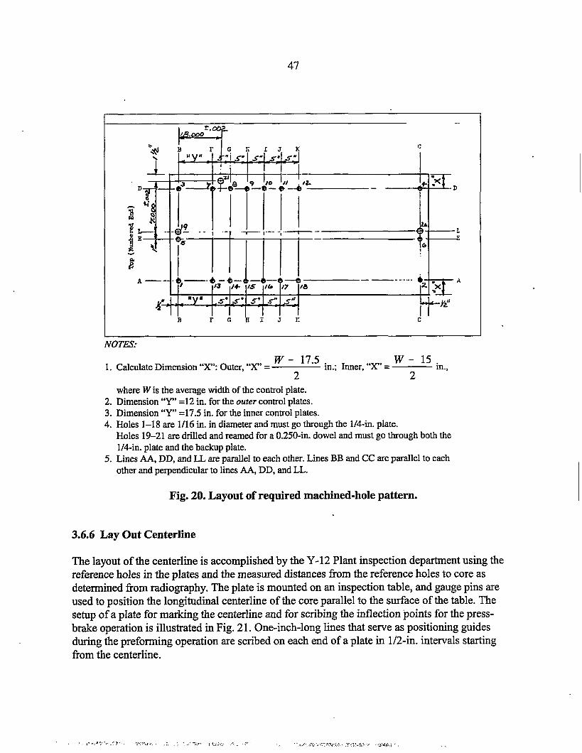
47
I@QQ=r..
NOTES:
1.
2.3.4.
5.
CalculateDimension“X”:Outer,“X”=w - 17.5 W-15
in.; Inner,“X”= in.,2 2
whereW is the averagewidthof thecontrolplate.Dimension“Y’ =12in. fortheouter controlplates.Dimension“Y’ =17.5in. fortheinnercontrolplates.Holes1–18 are 1/16in. in diameterandmustgothroughthe W-in.plate.Holes19-21aredrilledandreamedfora 0.250-in.dowelandmustgothroughboththel/4-in.plateandthebackupplate.LinesAA,DD,andLLareparalleltoeachother.LinesBBandCCareparallelto eachotherandperpendiculartolinesAA,DD,andLL.
Fig. 20. Layout of required machined-hole pattern.
3.6.6 Lay Out Centerline
The layout of the centerline is accomplished by the Y-12 Plant inspection department using thereference holes in the plates and the measured distances from the reference holes to core asdetermined from radiography. The plate is mounted on an inspection table, and gauge pins areused to position the longitudinal centerline of the core parallel to the surface of the table. Thesetup of a plate for marking the centerline and for scribing the inflection points for the press-bralce operation is illustrated in Fig. 21. One-inch-long lines that serve as positioning guidesduring the preforming operation are scribed on each end of a plate in l/2-in. intervals startingfrom the centerline.

48
Fig. 21. Plate setup for marking centerline and for scribing inflectionpoints for press-brake operation.
3.6.7 Press-Brake Forming
The preforming of the cylindrical shape of the control plates is accomplished in an incrementalfashion using a conventional press brake and a ~bber pad-type forming process. This processuses a metal punch attached to the ram having an 8-in. radius and a solid rubber striker pad diemade from 75-durometer polyurethane rubber. Retractable pointers at each end of the punch areused to align the punch with the inflection points scribed on the control plates. To compensatefor end deflection, a 3/16-in.-thick shim, 18 by 12 in., is placed under each end of the rubber pad.Additional shims may be required. The punch and die arrangement used to form control plates isshown in Fig. 22. This lype of incremental forming operation was selected over single-stepforming during the initial development phase to minimize the chances of breaking the coresduring forming. The forming of a control plate is accomplished in 1-in. increments with a platebent only slightly during each press adjustment (0.025-in. adjustment in press stroke). The plateis rotated 180° between press adjustments, offset 1/2 in., and the operation is then continued in1-in. increments. It takes 12 to 16 h to preform each plate. The appearance of a control plateduring preforming is shown in Fig. 23, and a completely formed plate is shown in Fig. 24.

49
Fig. 22. Punch and die arrangement used to form control plates.
Fig. 23. Control plate during preforming operation.
.... .. . . . . . ... . .-, “..<,..... ..... .... .. ..- -, ----- . .. ...

50
The required final preformed inside e,-.~....:,’radius is 9 “1/8+ 1/8 in. for the inner and $~’”-’.,~9 3/8+ 1/8 in. for the outer control plate. ‘” ~~Because the control plate is incompression during forming, the radiuswill be -1/8 to 1/4 in. smaller afterremoving the backup plate. Tocompensate for this spring effect, theplates must be preformed to a greaterradius with the backup plate attached.The plates are preformed to a radiusneeded for explosive sizing, which is-1/4 to 3/8 in. greater than the finishedplate radius. For explosive sizing, thelarger radius is important to minimize Fig. 24. Completed preformed control plate.the “spring in” of the edges duringexplosive sizing. Some considerations have been given during several campaigns to eliminateexplosive sizing and directly form the radius on the press brake. Plates with the correct radiushave been formed on the press brake, but the ability to consistently achieve the correct radiuswithout some bow along the centerline has not been demonstrated. For inner plates, it might bepossible to eliminate the first explosive sizing operation, but for the outer plates, it is highlyunlikely that the explosive sizing operation can be avoided.
3.6.8 Remove Backup Plate
After the control plate is preformed, the backup plate is removed and discarded. The backup plateis removed by heating the composite control backup plate from the control plate side to allow theepoxy to soften so that the control plate will release and fall away from the backup plate.Exposed calrod-type heaters in a special fixture are used to heat the composite. The heating unitand a control plate with a backup plate positioned on the heating unit for removal are shown inFigs. 25 and 26. A thermal blanket is placed over the plates and the heating unit during heating toreduce the thermal losses. The plate must be heated to -220°C for the epoxy to soften sufficientlyfor removal. A plate should release within -30 min after heat is applied with the fmture. Duringheating, the release can be hastened by using a screwdriver on the ends as a wedge to loosen theplate. Some difficulties were encountered in controlling the temperature of the heating unitduring the last campaign because the epoxy on several plates charred during debonding. For thebest results, a small thermocouple was placed in one of the radiography reference holes along theedge of a plate, and the temperature was controlled manually.

51
Fig. 25. Heating unit for removal of backupplate from control plate.
Fig. 26. Plate positioned on heating unit.
3.6.9 Remove Epoxy and Clean
After debonding, the control plate will have varying amounts of epoxy remaining after releasingfrom the backup plate. The methylene chloride solvent used in previous campaigns for epoxyremoval could not be used at the Y-12 Plant because of environmental restrictions on its use.During the last campaign, the environmentally acceptable Peel Away-7 adhesive stripper wasidentified for use. The Peel Away-7 stripper is compatible with aluminum and is a paste-likematerial that is used in combination with covering paper (Peel Away paper). A relatively thickcoating of stripper is applied to a plate, the stripper paper is placed on top, and the stripper isallowed to stand on the plate 15 to 20 h. The softened epoxy is then removed with Teflonscrapers and cheesecloth soaked in alcohol. The stripper works effectively if the epoxy has notbeen charred. Charred epoxy and other residues not removed by the stripper are removed by lightgrit blasting after the plates are stress annealed.
,.

52
3.6.10 Stress Anneal
The plates are stress annealed at 412°C for 3 h to remove stresses introduced during thepreforming operation. In this operation, each plate is annealed separately on a special supportfixture (Fig. 27) using the same fkrnace used in the previous flattening and annealing step. Eachplate is fitted with two thermocouples to monitor thetemperature before it is placed in a preheated fi,u-nace.Aluminum foil is used between the fixture and the plate toavoid scratches fi-omthe differential expansion of the steelfixture and the aluminum plate. After heating for theprescribed time, the plate on the fixture is removed fromthe fiumace and allowed to cool to room temperature.
During the initial development of the control plateprocesses, apparently some considerations were given toannealing a control plate after the explosive sizingoperation. During forming, most of the stresses in acontrol plate are introduced during the preformingoperation. An additional annealing step after explosivesizing would introduce distortions that would make itdifficult to meet the required dimensions. For thesereasons, the final stress relieve anneal is performed afterthe preforming operation.
3.6.11 Positioning Holes
Two holes are drilled in the end margins of each plate on
Fig. 27. Fixture used to supportpreformed control plate for stress-relieve annealing step.
the centerline previously determined in the radio~aphy analysis to orient the plate in theexplosive-forming die. The hole at the top or cored end is round and 0.469 in. in diameter; thehole in the bottom end is a slot of the same diameter as the round hole but 0.750 in. long. Theseholes are drilled after preforming to avoid the distortions that would have occurred duringpreforming.
3.6.12 Inspection
The dimensional inspection of the plates after preforming consists of a verification of the correctradius for explosive sizing and of the size and location of the explosive-sizing positioning holes.Radius templates are used to veri~ that the correct radius for explosive sizing of 9 1/8 in. for theinner plates and 9 3/8 in. for the outer plates, both with a tolerance of +1/8 in., has been met. Acourtesy radiograph was made at this stage during the last campaign mainly to ensure that thecores had not cracked during preforming and to veri~ the centerline before shipping the platesfor explosive sizing.
.

53
3.6.13 Prepare Explosive-Forming Die
The explosive-forming die with the sealing fixtures is shown in Fig. 28. The holes on the topsi.uface of the die are for the attachment of lifting lugs and for charge-positioning bolts. Thenumerous holes on the inside surfaces of the die are for the attachment of the rubber sealingbladder, shown in the foreground, along with the sealing bars. Other holes in the die surface andalong the side of the die are for the evacuation of the die prior to explosive sizing. The explosive-forming die, which is made from hot-rolled carbon steel, was fabricated in the early 1960s andmust be cleaned and inspected before each campaign. During the last campaign, because ofsurface scratches and deformations from previous use and from rust pits, it was necessary toremachine the die surface. After machining, the die surface was hand finished to remove themachining marks. Small protrusions on the die surface will be embossed into the plate surfaceduring explosive sizing and must be removed. The threaded holes were also chased and cleaned.The top threads in several of the holes used for tightening the sealing bars were worn to a pointwhere extra-length bolts were required. After cleaning, the die surface was covered with a motoroil film to prevent rusting. The oil film is main~ined while the die is being stored and is removedjust before use.
.
Fig. 28. Explosive-forming die with sealingf~es.
3.6.14 Package and Ship
Because an outside contractor was used, it was necessary to package and ship the die hardwareand plates to Sequim, Washington. A special plywood box was made to protect the die duringshipment. The plywood boxes for the control plates had padding and wooden braces to protectand minimize plate movement during shipping. The die, accessories, and the first group of plateswere shipped on a special-use-dedicated cross-country truck to minimize handling. The second
.
. . .. . . . .... ..—...=_ . . . ,, ___ .-5—.. .... -..---.. .,.

54
group of plates and all plates returning to Oak Ridge were shipped by air freight. Other thanweather delays with almost all shipments, no problems were encountered with the plates or thedie from shipping.
3.6.15 Assemble Plate in Forming Die
The same die is used for forming both the inner and the outer plates. For an outer control plate,the explosive-forming die stiace is in direct contact with the control plate. For the inner plates, aformed 0.375-in.-thick aluminum plate is used to shim the die to the correct radius. The detailedprocedures for the assembly of a plate in the forming die and the explosive-sizing operation wereextensively rewritten during the last campaign. The setup of the die consists mainly of attachingvacuum lines to the die. The die should be positioned on a work surface that is -20 in. high toallow a comfortable working position for performing the many tasks required for loading andunloading plates from the die. In preparing a die for sizing a plate, the die surface is thoroughlycleaned with lint-free cloth wetted with alcohol and wiped dry with tack cloth just before a plateis placed in the die. It is extremely important to remove all lint, threads, and other similarmaterials because any materials that are left on the die surface will be embossed in the platesurface from the explosive-forming force. No lubrication is used on die or bladder surfaces.
Before a control plate is placed in the forming die, all sharp corners and burrs are removed byfiling the plate edges to allow the plate to be properly seated in the die and to minimize thepossibility of the plate cutting the bladder during explosive forming. The locating holes arechecked by inserting a spare locating dowel, and any burrs are removed. The plate is first wipedwith an alcohol-wetted lint-free cloth and then wiped dry with tack cloth just before positioningin the die. Again, it is very important to remove all lint, threads, and similar materials from thedie and plate surfaces. The plate is then positioned in the die cavity by carefully aligning theplate’s two locating holes over the die locating pin holes. The locating pins are then screwedthrough the plate into the die with the pin in the round hole positioned first. Care must be takennot to slide the plate on the die surface to avoid scratching the plate. The surface condition of thelocating pins is important because we experienced some difficulties in removing the pins afterexplosive forming in the tit series of plates formed, and several pins were damaged duringremoval because of galling. During the forming of the last five plates, the pins were lubricatedwith a thin coating of stearic acid, which essentially eliminated the problem. The stearic acid wasapplied by dipping the pins in an alcohol slurry containing the lubricant. The preformed platepositioned in the die will likely have some bow that will allow the plate to rock slightly (-1/4 to1/2 in.) on the pins. Afler the plate is positioned in the die, beveled aluminum strips are placedalong the long edges and rubber strips are placed along the ends to provide a transition from theplate edges to the rubber bladder. This transition is necessary to decrease the stresses in therubber along the edges to avoid cutting the rubber bladder during explosive forming. Thepositioning of the transition strips in the more bowed plates is more tedious. In positioning therubber bladder over the plate, care must be taken not to dislodge the transition strips, which couldresult in scratching the plate.

.
55
In previous campaigns, it was found that the l/4-in. -thick gum rubber bladder needed to be cut toa slightly larger size (-1/2 in. on each side) than required for a perfect fit to obtain consistentsealing of the evacuation bladder. With the designed clamping arrangement, the vacuum tends topull a stretched bladder away from the bolt holes and clamping bar, which can result in a leakpath. The bolting of the slightly oversized bladder requires that one side be bolted first and thenthe excess material puckered while the other side is bolted. During clamping, it is important tomaintain the position of the transitions strips. The bolting of the sealing strips is first done with
“an air impact wrench and then hand torqued to a specified level after all bolts have been insertedand seated. The end sealing strips must be individually matched to the hole patiem in the die.
One potential problem that was observed with the bolted clamping arrangement late in the lastcampaign was the possibility of shredding the rubber bladder around the bolt holes whiletightening the fill-threaded bolts that were used. Bits of shredded rubber were observed on theconvex side (die side) of two plates afier explosive sizing that caused embossed impressions intothe plate surfaces -0.003 in. deep. The discovery of this problem came too late in the lastcampaign to correct, but the use of smooth-shank bolts with lubrication should be considered tocorrect this problem in the future.
The evacuation of the bladder is performed with a mechanical vacuum pump. The initialevacuation should be petiormed slowly to allow the excess bladder material to move andconform to the cavity and plate surface. Afier evacuation, the bladder surface should be perfectlysmooth with the locating pins obviously protruding into the rubber bladder. The evacuation will .seat the plate completely in the die cavity. Apparently in the initial development of the explosive-forrning technique, a special clamping arrangement was used to seat the plate into the die cavitybefore evacuation. According to the Y-12 Plant staff experienced in explosive forming, thistechnique has not been used in recent memory. The evacuation of a control plate to <–26 in. Hgshould be achieved in 5 to 10 min if the bladder is not leaking. To achieve the full blank-offvacuum of –29 in. Hg, the mechanical pump requires 30 to 60 min to out-gas and remove theresidual water from the stiaces. The assembly is considered leaktight if the blank-off vacuumprekmre does not change after the vacuum pump has been shut off from the assembly for 5 min.Retightening the bolts maybe necessary if a leak is observed. During the last campaign, it wasnot necessary to disassemble the bladder to obtain the required vacuum and leak rate for any shot.
3.6.16 Explosive Sizing
Afler the evacuation of the die cavity, three wooden charge-positioning strips with locating holesfor the explosive charge are aligned and positioned above the plate surface. The strips are locatedto position two strands of Primacord 10 in. above the horizontal centerline of the die surface and5 in. offset from the centerline. Explosive sizing is accomplished under a water head of >5 Rwith two strands of 50 grairdl Primacord detonated with four detonators (No. 4 or No. 6) thatare activated simultaneously. The stringing of the explosive Primacord and the attachment of thedetonators are done at the blasting tank because of safety concerns. The Primacord is cut in96-in. lengths to allow a sufficient length to knot the ends for stringing the Primacord between
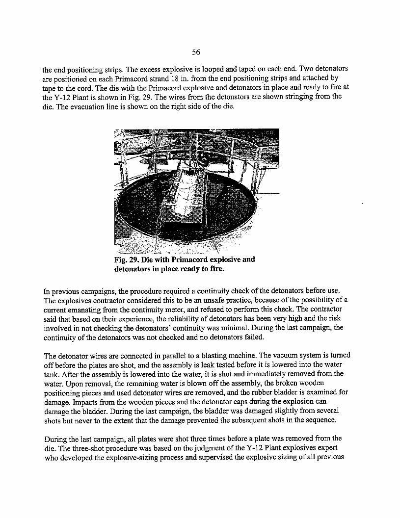
56
the end positioning strips. The excess explosive is looped and taped on each end. Two detonatorsare positioned on each Primacord strand 18 in. from the end positioning strips and attached bytape to the cord. The die with the Primacord explosive and detonators in place and ready to fire atthe Y-12 Plant is shown in Fig. 29. The wires from the detonators are shown stringing from thedie. The evacuation line is shown on the right side of the die.
*-><./ --Ar: .+3 , : ~ .“<,:+, ~ :“.,, ~“<. $
Fig. 29. Die with Primacord explosive anddetonators in place ready to fire.
In previous campaigns, the procedure required a continuity check of the detonators before use.The explosives contractor considered this to be an unsafe practice, because of the possibility of acurrent emanating from the continuity meter, and refused to perform this check. The contractorsaid that based on their experience, the reliability of detonators has been very high and the riskinvolved in not checking the detonators’ continuity was minimal. During the last campaign, thecontinuity of the detonators was not checked and no detonators failed.
The detonator wires are connected in parallel to a blasting machine. The vacuum system is turnedoff before the plates are shot, and the assembly is leak tested before it is lowered into the watertank. After the assembly is lowered into the water, it is shot and immediately removed from thewater. Upon removal, the remaining water is blown off the assembly, the broken woodenpositioning pieces and used detonator wires are removed, and the rubber bladder is examined fordarnage. Impacts from the wooden pieces and the detonator caps during the explosion candamage the bladder. During the last campaign, the bladder was damaged slightly from severalshots but never to the extent that the damage prevented the subsequent shots in the sequence.
During the last campaign, all plates were shot three times before a plate was removed from thedie. The three-shot procedure was based on the judgment of the Y-12 Plant explosives expertwho developed the explosive-sizing process and supervised the explosive sizing of all previous

57
control plates. He indicated that many plates sized in the past have required multiple shots toachieve the desired contour. Some plates have been shot as many as eight times. With multipleshots, the main concern is that the sides of the plate will spring in slightly. If this occurs, thecondition can be corrected with the press brake after the sizing operation. The reshot of theassembly requires a repeat of the sequence starting with positioning new wooden chargepositioning pieces. The rubber bladder is retightened between shots. The reshot sequence can beaccomplished in less than 30 min.
After completion of an explosive-forming operation, the die assembly is returned to the workarea and the plate is removed from the die. In this operation, the remaining water is blown offand the surface is dried with wipes before the clamping screws are removed to minimize watergetting on the plate and die surface. After explosive sizing, a plate will be in direct contact withthe die cavity with no obvious clearance. When a plate is being removed from the die, thelocating pins are first removed and the plate is carefidly lifted on one end by prying with a thinblade until the plate can be lified by hand. As indicated previously, the removal of the locatingpins can be difficult and must be done carefilly to avoid bending or breaking the threaded stem..
3.6.17 Inspection
Inspection, at this point, is to veri~ that the sized control plate has been properly formed and isacceptable for further processing. For the outer control plates, the contour afier this step is in itsfinal form and must meet the final outer radius of 9.30 in. + 0.020 in. The inner plates aresubsequently welded together to forma cylinder, and their final contour is established byexplosively sizing the welded cylinder. Resizing of an outer plate is required if the radiusvariation is X1020 in. or if the established centerline does not allow a minimum edge clad aftermachining of 0.125 in. in the black region. In the last campaign, all plates met the required edgeclad thickness and two plates required minor press-brake resizing.
3.6.17.1 Visual inspection
Immediately after explosive forming, the radius of each plate is checked with an inside radiustemplate (8.675 in. for the inner plates; 9.050 in. for the outer plates) along its length in -1 -ftincrements to ensure that the radius of the formed plate is within 1/8 in. of the template size. Thebow is evaluated with a metal straight edge placed along the centerline of the plate. Theclearance between the plate and the template, or straight edge, is evaluated visually and withpaper or plastic feeler gauges. Plates explosively sized during the last campaign were well withinthe specified radius and bow requirements. All plates had no visible bow and most plates hadalmost no clearance (<0.005 in.) between the template and the plate. Two or three platesexhibited a small amount of spring (<1/16 in.) along the edge. The surfaces of the plates werevisually inspected for stiace defects. As mentioned previously, two plates had some smallembossed areas, apparently from the rubber shards that were imbedded in the plate surface.
. .... . . . .... ... . .. .. ... ?+Y,-.. ..>m~- . - --- ------ , . -., .-

58
Fig. 30. Fixture for positioning curved control platefor radiography.
3.6.17.2 Radiography
The radiography at this stage is to veri~ that the cores were not damaged from the explosive-sizing operation and to determine the location of the core from the plate edges. The radiographyof the curved plate is performed with a special fixture (Fig. 30) that allows the alignment of theplate segment to be x-rayed near to perpendicular with the X-ray source to minimize divergence.Relatively small segments of the plate are radiographed in individual exposures to improve theresolution of the edge dimensions (17 radiograph shots for outer plates and 18 shots for innerplates). The location of the core from the plate edges is determined from the radiographs usingthe distances measured from the reference holes to the core edge. The measured distances on thecurved plates from the longitudinal edges to the core are smaller than like measurements taken onthe flat plate because of the deformation of the core edges during forming.
3.6.17.3 Contour inspection
The inspection of the contour of the sized plate is performed on an inspection mandrel mountedon the bed of the mill with the index head and center that will be used to machine the plates. Forinspection, the plate is mounted on the inspection mandrel in an unrestrained stress-free state. Amaster gauge template is mounted on one end of the inspection mandrel. In the last campaign, anew gauge for the outer plates was made by precision electric-discharge machining and theninspected to determine the precise dimensions (0.0001 in.) of the reference surfaces. A separategauge is used for the inner plates. The inspection mandrel with the master gauge attached inshown in Fig. 31. The master gauge is on the right end of the mandrel in the photograph.The attachment of a plate to the mandrel is done with shims in a manner that will not impart anystains, and a dial indicator is used to ensure that the contour has not been disturbed duringclamping. In setting a plate on the mandrel, the design radius (8.925 in. for the inner plate;

59
Fig. 31. Inspection mandrel with master gauge attached.
9.300 in. for the outer plate) is set 3 in. from each end of a plate at the “best-fit centerline” byshimming the plate at its edges. The best-fit centerline is defined as the axis fi-omwhich thecontour deviates equally from the segment’s outside radius. The best-fit centerline is establishedby using a dial indicator and by rotating the mandrel with the index head and moving the plateuntil the deviation of the indicator is equal on both sides when the mandrel is rotated (splittolerance). Typically, a control plate requires several position adjustments to establish the best-fitcenterline.
.
The inspection of the contour consists of determining the radius dimension along the centerlineand along the four lines on each side of the centerline 1 5/8 in. apart by making axial traverses. Aplate is considered satisfactory if the radius varies +0.020 in. from the design radius. During thelast campaign this contour inspection was determined on the machine tool bed using dialindicators. If the deviation exceeds the tolerance, the contour must be corrected by returning thepart to press-brake forming and explosive sizing. In the last campaign, the contour of two plateswas adjusted with the press brake without significant difficulties. If re-explosive sizing isrequired, a plate must be returned to the press brake to open the radius to the size required forexplosive sizing.
3.6.17.4 Centerline Comparison
The best-fit centerline (CL-2) is compared to the centerline determined before forming (CL-l). Amaximum variation of 0.050 in. between the two centerlines is allowed. If these centerlines varyby more than 0.050 in., it may be necessary to re-form the plate because the core location maynot permit a minimum edge clad thickness of 0.125 in. after machining. If it is necessary to
<,.+

60
re-form a plate because of a centerline problem, the plate must be flattened and carried throughthe entire forming and sizing sequence starting with the flattening anneal. To veri& thelongitudinal edge clad thickness before machining, punch marks are made in the edges of theplate from CL-2 at equal arc lengths (13.605 in./2 for the outer plates) for use in radiography. Inradiography, a 0.0 10-in.-diam tungsten wire is stretched between the punch marks and thelongitudinal edge clad thicknesses is measured on the radiograph from this wire. The minimumallowed longitudinal edge clad thickness is 0.125 in.

61
3.7 FABRICATION OF OUTER CONTROL ROD
The majority of the fabrication of the outer plates that makeup the outer control rod isaccomplished on a large numerically controlled 6-in. horizontal boring milling machine usingmandrels mounted between a precision index head and a live center end stock. This same setupwas used with the inspection mandrel to determine the best-fit centerline described in theprevious section. The inspection mandrel and a Bridgeport milling head are used in theattachment of the end fittings and final machining steps. The machining setup and the proceduresused during the last campaign were slightly different from those used previously, mainly becauseof the improved capabilities of numerically controlled machine tools. These procedures arecontained in Y-12 procedure AA6-T-71 96-61, Rev. C.
3.7.1 Lay Out Centerline and Machine Edges
The mandrel used for layout of the centerline and machining the edges is made of steel with analuminum shim machined to the nominal inside radius of the outer plate (9.050 in.) attached tothe steel cylindrical mandrel. The shim is undercut about 0.015 in. in the areas where the platewill be machined. The arrangement of the mandrel positioned on the machine tool with clampsfor machining the longitudinal edges is shown in Fig. 32. The clamping arrangement of the plateto the mandrel shown in the figure is used in the layout of the centerline and machining. Theplate is positioned on the mandrel in a manner that will not deform the Iieestanding contour ofthe plate and reposition along CL-2 previously determined.
Fig. 32. Clamping arrangement of outer plate for machininglongitudinal edges.
.,..- ,,....... . ...... . . . . ,.,G-=-Y,-, ., r .,...’-..., -Y , , ,* . .. ,- .,,

62
The layout of the correct centerline before machining of the longitudinal edges is extremelyimportant because of the narrow (O.125-in. rein) edge clad in the outer control plate design. Thenominal longitudinal edge clad for the inner plates is 0.438 in. for comparison. The minimumlongitudinal edge clad of 0.125 in. in the black section is required to allow the machiningof450bevels required for clearance of the track bearing for the inner control plates during installation inthe reactor. The bevels are machined in the plate edges near the gray/black interface as one of thefinal machining steps.
The layout of the final centerline (CL-3) for machining is the centerline determined usingdistances measured on the last radiographs fkom the reference holes to the edges of the linesestablished from the best-fit centerline (CL-2). In establishing trim lines for machining, equal arcangles (41 054’ and 30”) from CL-3 are measured on each end, and marks are scribed on theplate at these locations. CL-3 should not deviate more than 0.050 in. fi-omthe flat plate centerline(CL-1) or more than 0.030 in. if the two centerlines do not cross. The scribe marks from CL-3should agree with the marks from the best-fit centerline (CL-2). During the last campaign, CL’3was ahnost coincident with CL-2 on all plates fabricated.
After the layout of the side edges for machining, the edge margins are verified by radiography. Inthis courtesy radiograph, a O.010-in.-diam tungsten wire is strung on the convex side of the partbetween punch marks at the ends of the trim layout lines. The distance fi-omthe wire marking theedge of the part to the boundary of the core section is measured on radiographs. The results ofthese measurements in the O-93 series plates are shown in the following table.
Right side Lefi side
Plate number Max Min Max Min
O-93-2 0.330 0.210 0.200 0.0700-93-3 o.~]() 0.]7(3 0.2]() 0.0300-93-5 0.360 0.250 0.270 0.1100-93-6 0.230 0.160 0.260 0.1700-93-7 0.200 0.130 0.250 0.1000-93-8 0.270 0.190 0.140 0.2100-93-9 0.280 0.190 0.280 0.220
0-93-11 0.160 0.140 0.230 0.1400-93-12 0.260 0.210 0.280 0.220
As shown in the table, several of the edge margins are less than the specified minimum of 0.125in. Based on this information, the trim lines were adjusted to center the europium core sectionwithin the plate.

63
The longitudinal edges are machined using an end mill cutter as shown in Fig. 32. The machiningof an edge requires several passes. After each longitudinal edge has been machined, the corddistance should measure 12.424 in. If the cord distance is >12.430 in., equal stock should beremoved from each edge.
The machining of the end clad requires a clamping arrangement illustrated in Fig. 33. Aftermachining of the longitudinal edges, this clamping fixture is positioned along the longitudinaledges of the plate. The location of the top or the end containing the core is determined frommeasurements made on the flat plate radiographs from reference hole 19. A small punch mark ismade at this location, and the top end is machined perpendicular to CL-3. The location of thebottom end is determined by measuring 66 3/16 in. from the top end down the plate. The bottomend is machined perpendicular to CL-3. The machining of the end was accomplished using theindex head to manually rotate the mandrel holding the plate under the end mill cutter. Severalpasses are required to machine the ends. After machining, the planes of the ends need to beparallel within A 0.002 in. for the proper positioning of the end fitting brackets.
.
Fig. 33. Clamping arrangement for cutting end clad onouter control plates.
3.7.2 Drill l/4-in. Holes
A large number of l/4-in. -diam holes are drilled in the white (aluminum) and gray (tantalum)regions of each plate. These holes are pressure-equalization holes required to reduce hydraulicforces on the plate during operation in the reactor. The 30 rows of 13 holes are drilled on a 1-in.grid on the bottom end starting 2 in. below the blacldgray interface, and on the top end 5 rows ofholes (4 rows with 13 holes and 1 row with 12 holes) are drilled starting 59 9/16 in. from the

64
bottom end. During the last campaign, the number of rows of holes on the bottom end waschanged from 31 to 30 to provide a larger margin around the europium core section.
The drilling of the 454 quarter-inch holes was accomplished using the same setup that was usedto machine the ends. A computer disk was used to load the required hole locations into thenumerically controlled mill. Before drilling, the hole pattern is verified using a felt marker inplace of the drill bit to mark the hole locations. In drilling, the drill passes through the plate andbarely enters the shim plate. Determining the correct bit geometry to drill a hole with therequired smooth surface required some development.
3.7.3 Radiograph
After a plate is removed from the fixture used for drilling the l/4-in. holes, the plate isradiographed to veri& the dimensions of the finished aluminum edging along the core andlongitudinal location of the core. The radiograph technique is identical to the technique used inthe previous curved plate radiograph inspections. The results showing the edge claddingvariations of the O-93 series plates is shown in Table 5.
Table 5. Edge clad margin measured on O-93 series outer control plates(side edges minimum is 0.125 in.; top and bottom are 2 in. nominal)
Top of plate Bottom of plateRight side Left side (to EuIA1 (to Eu/Ta
interface) interface)Plate number Max Min Max Min Max Min Max Min
O-93-2 0.290 0.200 0.255 0.135 “2.28 2.10 1.95 1.810-93-3 0.175 0.125 0.220 0.195 1.95 1.74 0.94* 0.76*o-93-5 0.355 0.250 0.305 0.175 2.33 2.06 1.96 1.830-93-6 0.215 0.205 0.270 0.210 2.63 1.83 2.14 1.450-93-7 0.265 0.190 0.330 0.200 1.81 2.82 2.40 1.290-93-8 0.255 0.190 0.260 0.225 2.10 1.98 2.11 2.020-93-9 0.200 0.270 0.250 0.180 2.35 1.87 1.03* 0.58*
0-93-11 0.215 0.185 0.250 0.230 2.38 2.34 2.07 2.050-93-12 0.290 0.260 0.225 0.225 2.14 2.07 1.94 1.87
Note: *Additional row of l/4-in. -diam holes; all previously fabricated plates made in thismanner.
As shown in the table, all the plates met the minimum side edge cladding of 0.125 in. Two plateswere inadvertently drilled with an extra row of l/4-in. -diam holes as specified in the previousdesign revision. This is the reason the bottom edge on two plates is outside the nominal 2-in.measurement.

65
3.7.4 Radius l/4-in. Holes
The hydraulic demands of the HFIR control systems requires that the drilled holes be radiused onboth sides and free of all burrs and tool marks. The specified radius is 1/32 in. and must beblended to avoid sharp edges. Before radiusing, the platesurfaces are sanded and polished to remove surface defectsgreater than 0.0005 in. ne removal of the surface defectsbefore radiusing is required to avoid repeating theradiusing operation because the removal of surface defectswill likely alter the hole radii.
A special router-type tool is used to the radius the holes.The radiusing tooling being used on the concave side of aplate is illustrated in Fig. 34. The tool is fitted with a footthat is contoured to match the plate contour and locatingdowels to position the tool over a hole to be radiused. Thedowels are positioned in adjacent holes to locate the toolprecisely over the hole to be radiused. The depth of the cutis established on a dummy plate and locked into place onthe tool against a positive stop. The cutting tool is raisedand lowered with a hand-operated cam mechanism. Thecutter is equipped with a nylon bushing to align the cutterin the hole to be radiused and is continuously lubricatedwith alcohol during cutting. The hand finishing andradiusing of each plate is a laborious tasks that requiresfrom several days to a week or more to completeeach plate.
3.7.5 Dimensional Inspection of Plate
After completion of the trimming, hole drilling,and radiusing, each plate is inspected to ensurethat the plates conform to drawing dimensionaltolerances before atichment of the end brackets.In previous campaigns, this inspection wasaccomplished on the horizontal boring machinetool using the inspection fixture and referencegauge. An outer control plate setup forinspection on the machine tool bed is illustratedin Fig. 35.
Fig. 34. Tool used for radiusingl/4-in. -diam holes on outer controlplate.
Fig. 35. Outer control plate setup forinspection on machine tool bed. The mastergauge is shown on the left side.

66
The Y-12 Plant inspection department would not certi$the dimensions measured in this manner, and during thelast campaign, a precision Mauser CMM inspection devicewas used to determine the dimensions and contour of theplates. An outer control plate on the Mauser CMM isshown in Fig. 36. Many of the dimensions of the platesdetermined on the CM_Mdid not conform with thetolerances specified on the engineering drawing. Thedimensions of the plates are referenced from the reactorcenterline from the bearing lugs while the plate is locatedin the reactor. Most of the out-of-tolerance conditions willbe effectively corrected when the bearing flanges areattached and the bearing lugs are finish machined. Tounderstand the effects of the out-of-tolerance radiuscondition, a computer-aided design (CAD) layout of theworst out-of-tolerance plate was prepared. The layoutshowed that the clearance between the outer control plateand inner control rod would not be seriously compromised(0.136 in. minimum compared to 0.170 in. nominal) not
Fig. 36. Outer control platemounted for dimensionalinspection on the Mauser CMM.
considering the likely increase in radius when the flanges are attached. Based on this analysis, itwas decided to proceed with the attachment of the flanges and final machining of the plateswithout tier rework.
To compare the out-of-tolerance dimensions measured with previously manufactured plates,three randomly selected outer control plates made in the 1976 campaign and previously acceptedfor reactor use were measured on the CMM. ,This comparison is shown in the following table.
Requirements Drawingtolerance 1993series 1976series(in.) (8 plates; k.) (3 plates; in.)
Perpendicular(top) 0.005 OK 0.007Perpendicular 0.028 0.008(bottom)
Radiuscontour * 0.0125 +0.020/- 0.022 +0.0291-0.028profileParallelism(side 1) 0.005 0.024 0.033Parallelism(side 2) 0.024 0.015Radius (top) 9.295/9.305 9.207 9.278Radius (bottom) 9.237 9.323
As shown in the table, the 1976 plates had out-of-tolerance dimensions similar to those measuredin the current campaign, except the radius of the 1993 series plates was smaller than the 1976plates. The smaller radius of the 1993 plates maybe related to the rework of the explosive-forming die, the radius of the plate before explosive sizing, or the use of three explosive shots insizing.

67
3.7.6 End Fitting Preparation
End fittings for both the top and bottom flanges are made from 6061 aluminum plate. The initialplan in the 1993 campaign was to reuse the flanges removed from the 1976 series outer controlplates. As the drilling and final machining of the flanges are accomplished on the plates and arecustom fitted to each plate, the use of previously used flanges was determined not to be practicalin meeting the dimensional tolerance requirements, particularly for the bearing lug locations. Inaddition, the weld quality on some of the 1976 series flanges was questionable.
Previously, end fittings have been made as a weldment, but during the last campaign the designwas changed to make the fittings from a single plate piece, primarily to avoid welding and toreduce fabrication time and costs. The initial wekhnent design was made in the early 1960s, butsince that time advances in numerically controlled machinetooling have made fabrication of the end fittings from a singlepiece of aluminum stock practical and cost effective. Inaddition, the quality assurance documentation requirements ofa weldment for a nuclear application is a significant time andcost factor in fabrication. In the fabrication of the end flanges,the rough machining is accomplished on an electric dischargewire cutting machine tool. A rough-cut bottom flange cut froma 5-in.-thick aluminum plate is shown in Fig. 37. The topflanges are cut from a 3-in.-thick aluminum plate. Finish“machining is accomplished on a numerically controlled millingmachine.
A materials issue in fabrication of the plates from a singlepiece of stock was the temper of the bearing lugs and theheat-treatment requirements. The thick plate stock is receivedin the T-6 temper as specified for the bearing lug in theprevious design. A partial stress-relieve anneal after roughmachining was specified at 350 “F to maintain the temper ofthe bearing lugs. The stress-relieve anneal conditions werepatterned after conditions used in the manufacture of HFIRfhel elements.
The finished machined end fittings for an outer control plateare shown in Fig. 38. The bottom end fitting, shown in thetop of the figure, has a ring for attachment of the reactor drivecoupling. Both the bottom and top fittings have two bearinglugs for attachment of track bearings. The bearings attachedto these lugs ride in a track that serves to guide the outer plateas it moves between the inner control cylinder and theberyllium reflector. In the attachment of the end fittings, the
I::
1
Fig. 37. Rough-cut bottom endflange for outer control plates.
~/..A, , ,. ..:,.,.
... .._ “
Fig. 38. Finished machined topmd bottom flanges beforeattachment to outer control31ate.

68
position of these bearing lugs is most important to ensure proper operation of an outer plate inthe reactor. The inside radius of the end fittings is machined to a 9.300-in. radius to match thenominal outside radius of a formed plate.
3.7.7 Attachment of End Fittings
The attachment of the end fittings and final machining are performed on the same mandrel usedfor the inspection of the contour after explosive sizing. In the setup for the attachment of the endfillings, a Bridgeport milling head is placed on the boring machine’s spindle. A plate positionedon the mandrel for attachment of the end fitting is shown in Fig. 39. The master template isshown on the left. In the attachment of a plate to the mandrel, the plate must be positioned toavoid any deflections in the plate from its freestanding configuration. To ensure that the plate isnot deflected during clamping to the mandrel, dial indications are positioned on the centerlineand at the edges on each end. After a plate’s proper centerline location and edge positions areestablished on the mandrel. the clanmin~ Rads are. -.adjusted to minimize deflection of the plate duringclamping. Using screws through two of the l/4-in. -diam coolant holes to hold the plate’s centerlinesignificantly reduced the time required forpositioning a plate on the mandrel. The maximumallowable deflection is 0.002 in. when the clampsare released and retightened. The purpose of thissetup is to have the plate positioned on the mandrelin the exact position used during the previousinspection, except that the centerline axis is offset0.041 in. The final inspection of a plate is made withrespect to the master template gauge, which also hasa 0.041-in. offset. The master template gauge is animportant element in the final machining operations,and its functions must be thoroughly understood bythe fabricators.
Either fitting may be attached first. In theattachment of an end fitting, “C” clamps are used tohold the fitting in the required position established
Fig. 39. Plate positioned on the mandrelfor attachment of the end fitting.
from the master template. A dowel hole is thendrilled on the centerline through the fitting andplate, and a l/4-in. dowel is inserted. The fitting andplate are then drilled, countersunk, and tapped. The fitting is then attached with screws. At thispoint, the attachment screws and end fittings are removed fi-omthe plate, deburred, and cleaned
The plate is then removed from the mandrel, the mating surfaces are cleaned again, and thefittings are reattached with the screws used previously. Each screw is torqued to 40 in.-lb and

69
loosened four times to ensure a proper fit-up of the fitting. After torquing, each screw is flaredwith a hydiaulic pressing future to prevent the screws horn backing out during operation in thereactor. The flaring tool uses a flat bottom punch with a centering stake for positioning thepunch in the center of the flat-head screw anda900 included angle top punch. A force of 2000 lbis used to flare the specially designed recessed screw,which protrudes 1/32 in. before flaring. The future usedfor flaring the aluminum screws is shown in Fig. 40.
During the last campaign, the back-off torque of theflaring process was evaluated as a fimction of flaringpressure. The evaluation showed that a back-off torque of40 to 50 in.-lb could be achieved at a 2000-lb force.Multiple torquing of the screws provided more consistentback-off torque values. A force greater than 2000 lb didnot increase the back-off torque and tended to excessivelydeform the plate surface. In earlier outer control platecampaigns, the screw heads were staked rather than flaredto prevent them from backing out. A cursory evaluation ofthe staking technique used showed the flaring process tobe comparable or better in back-off torque.
Afler attachment of the end fittings, the plate isrepositioned on the mandrel and the bearing lugs arebored and faced to size using the master template as the
Fig. 40. Fixture used for flaring thealuminum screws.
reference. This technique ensures that the bearing surfaces are within the tight tolerancesspecified on the design drawing. Using this machine setup, the 5/8-in. and 3/4-in. holes aredrilled on the centerline and the required bevels machined on the plate and fitting edges. Thesetup for final machining of the bearing surfaces and holes is shown in Fig. 41. The finalmachining operation is vibra-etching the serial number and the HFIR outer control rod set and setplate number on the top and bottom ending fittings of each control plate.
3.7.8 Final Dimensional Inspection
The finished outer control plate is inspected for compliance with dimensions and surface finishas specified on Eng. Dwg. E-49820 Rev. V, Outer Control Rod Assembly. The milling machineused in the final machining is used in the final dimensional inspection. Before the millingmachine can be used for final assembly, the milling machine must be checked for calibration andcertified for use.
... . .... . , ,.: ....-.7. . . . . . . . . . ~.. . . . . . . -- . . . . . ,- ><----- .- --- , . ,. .,,, .-,-

70
Fig. 41. Setup for final machining of bearing surfacesand holes.
3.7.9 Final Cleaning of Outer Control Plate
The final cleaning of the outer plates consists of an alcohol wipe and cleaning all holes withalcohol-wetted nylon bristle test-tube brushes. C&e must be taken to clean all surfaces and holesthoroughly to pass a final “white glove” cleanliness inspection. In most instances, recleaning ofsome of the holes was required to pass the cleanliness inspection. In past campaigns, finalcleaning was first done using a mild alkaline detergent solution (1 tablespoon Alconox MasterMix Cleaner per gallon in 160°C water) with a hot-water rinse followed by a final alcohol wipe.When this procedure was attempted with the available containers, considerable water spottingwas experienced on the polished aluminum surfaces. Because the final machining of the polishedplates and brackets is done using only alcohol as the cutting lubricant and final cleaning ofaluminum components with alcohol is an accepted practice in HFIR operations, the detergentwash step was eliminated. After cleaning, a plate is allowed to dry in air and then wrapped inplastic sheeting before being placed its individual transport/storage box. The use of compressedair is not allowed for drying to avoid oil or other contaminants that maybe present in thecompressed air source.

71
3.7.10 Bearing Installation
The design life of an outer control plate is typically 40 to 50 HFIR cycles, but the bearings mustbe replaced in the reactor pool after every 7 cycles during their use in HFIR. Replacementbearings are routinely procured and installed by the HFIR operating staff. On new outer controlplates, the bearings are installed by crafts personnel at the HFIR just before insertion into thereactor pool for use. The journal-type bearings are currently being manufactured of Haynes 25with a stainless steel shaft to very tight tolerances. The construction materials of the bearings willlikely be changed to Inconel X750 and PH3-8 tool steel with a stainless steel shaft in the nearfiture. In installation, a bearing is pressed onto a shaft, and the 0.440-in.-diarn shaft is pressedinto the hole bored in the bearing lug (0.0001 to 0.0003 in. interference fit). Finally, the shafi isdrilled and secured to the lug with a l/8-in. -diam pin that is secured by flaring. As a finalacceptance, the completed control plate assembly is subjected to a go/no-go check with a femaleclearance gauge (ORNL- Dwg. E-55098) at HFIR. The plate must pass through this gauge to beaccepted for use in HFIR.
During operations in the reactor and replacement of the bearings, the lug bearing holes increasedin diameter from this wear. To compensate for this wear, bearing shafts with diameters from0.440 to 0.446 in. are provided. The largest shaft used to date has been 0.445 in. In replacingouter control rod bearings in the reactor pool, the old bearing is removed, the lug bearing holediameter is measured, and a new bearing assembly with the proper shafl diameter inserted intothe lug.
,
... ~.,,-,., -y.~, ,.. . .- . ~,T,,~,.7$_v_ ---=X=lT?f.% , -.--— --- . . - ,. .<. . . .<

72
3.8 FABRICATION OF INNER CONTROL ROD CYLINDER
The inner control rod cylinder is composed of four plates, each of which has a black and graysection essentially identical to the poison section in an outer plate; the processing of the innerplates up to the point where the plates are welded into a cylinder is almost identical. Thedifference in processing of the inner plates is that the hot rolling cropping position is different,the formed curvature is a slightly smaller radius, the overall length is slightly greater, and thelongitudinal edges are wider. The poison section is also located in a different place than in theouter plates. The outside diameter of a finished welded cylinder is 17.846 in.
Inner control cylinders were last made in the 1984-87 time fiarne. The inner control cylinderprocesses described in this document are primarily a refinement of the information reported inOIUWJTM-9365, which was written in the late 1960s but not issued until 1984.ZThe informationwas updated by interviewing personnel who were involved in the last inner control platecampaign.
The flowsheet for fabricating an inner cylinder is shown in Fig. 42. The process consists ofwelding four formed plates into a cylinder, explosive sizing the welded cylinder, chillingnumerous l/4-in. -diarn holes and pressure-equalization holes, final machining, and attaching anend fitting.
3.8.1 Lay Out Centerline and Machine Edges
The layout of the centerline and the machining of the edges, except for the mandrel tooling andreference hole locations, are identical to the processes previously described for the outer plates.The reference hole locations are different primarily to differentiate between the two plate types.Because the width of the longitudinal core margins is significantly larger (0.435 in. nominal) forthe inner plates, the centerline layout is not as critical as it was for the outer plates.
The determination of the correct arc length for the plates to form a 17.846-in.-diam cylinderwithin -0.000/+0.0 10 in. by welding requires an understanding of weld shrinkage and theexpansion from the pkmishing step. The weld shrinkage measured in past campaigns indicatedthat the average weld shrinkage before planishing is about 0.060 in. with a variation of about+0.0 10 in. The planishing operation, which results in plastic deformation of the weld region, isnecessary to control the arc lengths of the individual plates to fabricate a cylinder within thespecification. Each planishing pass increases the arc length about 0.004 in. Up to 0.016 in. ofexpansion of a single weld joint was obtained in past campaigns in four planishing passes. Thearc length for each segment should be established to allow at least one planishing pass on eachweld joint to cold work the cast structure of the weld zone to improve its metallurgicalproperties. Based on the minimum weld shrinkage of 0.050 in. and 0.008 in. expansion fi-omtwoplanishing passes, the arc length for each segment should be cut to about 14.058 in. (14.016+0.050 – 0.008). This arc length value should be verified during cold tests in the next campaign.In the machine shop, the equivalent cord length is normally measured because it can be measuredaccurately with standard micrometers.

73.
Curved plates
I Machine ends II
aInspection
Dkncnsions
Contour
Inspect we!ds
I
I Scrape and planish welds
1
I Snmoth and finish welds I
1
Dirvmsional inspectbn 1
1
Face cylinder ends
JI Expbsive size cylinder
I
Machine ends
I
I Drill l/4-in.-di?m holes
I
I Remove sur!&ce defects II
I Radios holes II
I Final machrnmg II
Fabricate end fitting
304 smmless steel
I Formhachine components
1
inspection
Dimensions
Composition
1
We!d components
I
Shrink fit end tittingI
Screws Attach end lining I
I Ckan and package
I
Approved for HFIR use
Fig. 42. Flowsheet for fabrication of inner cylinder.
-.

74
To align the plates for welding, each plate is scribed 36 1/2 in. from the blacldgray interfacedatum on one end. The alignment of these circumferential marks ensures that the blacldgrayinterface is in the same horizontal plane in the control cylinder when operated in the reactor.
The longitudinal edges of each plate are beveledata370 angle with a l/32-in. land for obtaininga full-penetration weld. The fitup of the two beveled edges forms a groove for welding. Afterbeveling, parallel weld shrinkage marks are scribed on each plate on the inside surface 0.500 in.from the land”of the bevel edges. The machine setup for scribing the weld shrinkage monitoringline is illustrated in Fig. 43. The markings are not made along the region containing the europiumcore even though the markings are only about 0.002 in. deep.
Fig. 43. Machine setup for scribing weld shrinkagemonitor on inner control plate.
3.8.2 Welding
An external seain welder and a planishing roller are set up in a specially constructed, temporaryroom to provide a clean environment for performing and finishing the welds. A detaileddescription of the welding process development is contained in the WeldingJournal article ofOctober 1967 by Collins, et al. The components used in welding inner plates in past campaignsare listed below.
● Pandjiris external seamer modified● Linde side beam carriage● Linde wire feeder● Linde HW-13 heliarc torch with No. 10 metal cup● Miller SR-600 welding machine● Heliarc automatic head control panel, Model HMC-F● Planisher manufactured by Airline Welding and Equipment Company
.

75
A specially machined heat sink and chill clamps, made from copper and then plated with nickelto eliminate copper contamination, were designed to fit the Pandjiris external seam welder usedin past campaigns. To avoid having to make the relatively expensive heat sink and chill clamps inthe fidure, efforts should be made to use the Pandjiris seamer. The heat sink, which is machinedto the contour of the cylinder, serves as the backup bar and has a l/8-in.-wide byl/32-in. -deep semicircular groove down the center. This groove is used to position plates forwelding. The plates are welded together using the inert gas tungsten arc process (TIG) with fillermetal with the weld parameters automatically controlled. The weld is made using direct currentwith straight polarity, and helium is fed through the torch as the shield gas. The use of the 4043filler weld wire is absolutely necessary to weld 6061 aluminum without cracks because of thesilicon content in the 6061 aluminum.
An overall view of the seam welder being setup to weld two plates into a half cylinder is shownin Fig. 44. Shown in the top of the figure is the longitudinal side beam and carriage with thewelding torch and wire feeder mounted on the carriage. The heat sink is mounted on the cylindershown in the foreground, and the hydraulic actuated chill clamps are in the structure above thecylinder. The loose strap clamps shown in Fig. 44 are tightened after the parts have been clampedin the proper position to be welded with the chill clamps. A top view of the weld setup showingplates being aligned in the chill clamps for welding is shown in Fig. 45.
Fig. 44. Overall view of seam welder setup toweld plates in a half cylinder. Fig. 45. Top view of weld setup
showing plates aligned in chillclamps for welding.

76
Before welding, the surfaces of the plates are covered with paper and taped to within 2 in. of theedges to be welded to protect the plates from damage during handling. Run-off tabs, which are 2in. long by 3/4 in. wide with the same bevel and land of the weld joint, are then tack welded toeach end of each side of the segments to be welded. Immediately before welding, the surfacesand adjacent areas to be welded are scraped to remove any oxide layer. In the setup of two platesor half cylinders for seam welding, the edge of one plate or half cylinder is first aligned in themiddle of the groove in the heat sink and clamped into place. The edge of the second segment isbutted with the first segment, and the circumferential scribe marks are aligned and clamped. Themaximum allowable gap after butting is 0.010 in. at the ends and 0.020 in. in any other section. Ifthe maximum gap is exceeded, the edges must be reshaped by hand until the specified gaptolerance is achieved. The full clamping pressure of the chill clamps is not applied until after thesegments have been properly aligned and verified. The strap clamps are not installed until afterthe plates have been clamped with the chill clamps. Afler clamping, the distance between thehold-down clamps should provide a uniform 3/8-in.-wide gap. If necessmy, the hold-downclamps should be adjusted to achieve this distance because this gap distance will influence theweld width. .
In welding, the run-off tabs are first tack welded together. The tracking of the welding torch withthe weld groove is then checked to determine what lateral adjustments are necessary duringwelding. The welding torch is positioned ina50 forehand position. The welding electrode usedis 3/16-in.-diam, 2 0/0thonated tungsten that has been ground to a 160 included angle with al/32-in. flat tip. It extended 5/8 in. from the cover gas cup. The welding wire is l/16-in. -diam4043 aluminum welding wire. The welding parameters used to seam weld plates are listed in thefollowing table.
Pass Amperage Voltage Carriage speed Wire feed Shieldgas on(A) (v) (in.lmin) (in./min) torch
(@/h)
1 325+15 13*1 6 19 85
2 31O*I5 13+1 6 36* 85
*Note:The wire feed on second pass is adjusted by welder to obtain correct fill.
In welding, the arc is first struck on the run-off tab and the equipment is set for automaticwelding. A weld inspector is present during setup and all welding operations. After the first pass,the face side of the weld is brushed with a stainless steel brush to remove oxide and welddeposits. The weld inspector inspects the weld pass on the face side and, if necessary, thesegment is removed fi-omthe fixture to inspect the root side. Any visible surface defects arerepaired by a hand repair procedure before proceeding to the second pass. After the second pass,the part is removed from the fixture and the welds are visually inspected. Before removal of awelded segment from the fixture, heavy asbestos paper was installed between the mandrel and

77
the hold-down clamps to reduce the chances of scratching the part while it was being removedfrom the fixture. In fiture campaigns, asbestos paper cannot be used because of environmentalconsiderations and another suitable material will have to be identified. A cross section of atypical two-pass TIG weld in an inner control cylinder isshown in Fig. 46.
Afier machine welding, visible defects such as cracks andvoids are repaired by a hand repair procedure. The hand repairprocedure uses the W-607 TIG welding process, which uses ahand-held TIG torch with 3/32-in. -diam 4043 filler wire fed byhand. The visual inspection criteria were not well defined inprevious campaigns and need to be changed to reflect currentvisual inspection criteria like criteria defined in NDE-21.Terms such as “no visible defects” are not definitive.
3.8.3 Scrape and Planish Weld Surface
Fig. 46. Cross section of atypical two-pass TIG weld in aHFIR inner control rodcylinder.
After welding and visual inspection, each weld is scraped to remove the excess weld metal closeto the contour of the cylinder. The scraping operation is accomplished in a special fixture and atool similar to a wood plane is used to scrape the weld surface to a flat -0.010 in. above the platesurface. No more weld metal should be removed by scraping than is necessary to flatten the weldarea required for planishing. The scraping operation for both the inner and outer surfaces isillustrated in Fig. 47.
The planishing operation cold works the weld area andprovides abetter wear surface for the track bearingsthat ride in this area during operation in the reactor.The planishing operation is performed on a sheet metalplanishing machine. The device has two verticallymounted, crowned (5/16-in. crown) steel rolls that are5 1/2 in. in diameter and 2 7/8 in. wide. To providebetter tracking and alignment, a 7/8-in. -wide flat areawas ground into the circumference of the top roll. Thetop roll is driven by a constant-speed motor, and theforce between the rolls can be adjusted. In planishing,the force between the rolls is adjusted to 15 psi and theweld area is passed longitudinally under the rolls toshape the weld area. Two to four passes are required toplanish the weld area. The planishing operation willincrease the cord length slightly and can be used toadjust the radius in various areas if necessary.Typically, the circumference grows -0.009 in. after twopasses, but after two additional passes, it only grows an
Fig. 47. Scraping operation for innerand outer surfaces.
, . ., , ....-. -,-,.. .——. - . ... - 7 -,-

78
additional 0.005 in. During the planishing operation, a pi-tape is used to monitor the diameterchange. The measurements are made in specially identified locations at each end to ensureconsistent measurements.
Afler planishing, the weld area is scraped again in the scraping fixtures to remove excess weldmetal. The weld areas are then sanded with aluminum grit paper to restore the contour on boththe inside and outside stiaces. The thickness and inner and outer contours are repeatedlychecked with micrometers and an outside template gauge to ensure that the proper contour isobtained.
3.8.4 Inspection of Welded Half and Full Cylinder
The welds and dimensions on the welded half cylinders are inspected before being welded intothe fill cylinder using essentially the identical procedures that were used for half cylinders. Allwelds are radiographed with a film wide enough to allow the examination of the weld soundnessand to evaluate the alignment of the core sections. The weld radiographs are examined forabsence of cracks and voids in the Weld areas. The specification requires that the welded joint besound except for scattered porosity. The definition of acceptable porosity needs to be betterdefined in future campaigns using the criteria specified in Sect. VIII, Division 1, Appendix 4 ofthe Pressure Vessel and Boiler Code. The required width of the separation of the cores betweenplates is 3/4& 1/32 in., and the gray/black interface data must be aligned vertically to within 1/4in. of each other. Weld joint shrinkage isdetermined in the field by measuring theseparation of the scribe lines marked on theplates and with a pi-tape measurement of thearc. These measurements are comparable towithin about 0.005 in. of each other.
The tic length is inspected using a specialinspection fixture shown in Fig. 48. The gaugefixture has precisely determined arc lengthsmachined into the fixture, which are used asreferences for measuring the arc length of aplate or half cylinder. h end view of thefixture showing the machined reference landsis shown in Fig. 49. Shown in the fixture is ahalf cylinder positioned against a stop, whichis fastened to the land on the right side of thecircular gauge. In measuring the arc length of a
Fig. 48. Special inspection fixture used formeasuring arc length of a plate.
segment, one segment edge is clamped againstthe stop and the arc length is measured relative to the machined land on the left side. The arclength is measured in at least four locations: the ends and 22 in. from each end. If any individualmeasurement is not within within +0.006 in. of the average, additional measurements are made.

79
Two as-welded and planished cylinders from a previouscampaign had an average diameter of 17.851 in. and 17.849in. when the cylinders were measured with a pi-tape in 6-in.intervals. The individual diameters of each incrementmeasured ranges from 17.843 in. to 17.860 in. Afierexplosive forming, the average diameters of the samecylinders were 17.839 in. and 17.838 in., respectively, witha range in diameter from 17.836 ~. to 17.842 in. Thevariation in the radii of these two cylinders was significantlydifferent. The first cylinder, which was made before theplanishing operation had been perfecte~ had a maximumradius variation of +0.025 in. to -0.022 in.; the latter had amaximum variation of +0.005 in. to -0.007 in. This pointsout the need to establish a good procedure for the planishingstep during cold testing. Both cylinders were within the+0.030-in. radius variation allowed.
3.8.5 Face Cylinder Ends
Fig. 49. End view of inspectionfixture showing the machinedreference lands.
The datum for locating the core section in a control rod is the average gray/black interface. In awelded cylinder, because the distance from the core to the ends of each plate segment variesslightly, the ends of the cylinder will be uneven after welding. The facing of the cylinder ends isnecessary to provide smooth ends for the proper fitup of the cylinder in the explosive formingdie.
In facing a cylinder, the cylinder is mounted on a special expanding mandrel fixture and mountedon a machining lathe. The locations of the core sections were previously determined for the firstexplosive forming operation, and dowel-positioning holes were drilled in the plates at that time.The facing removes metal on each end back to the end of these positioning holes. Care isexercised during this operation to ensure that the markings at each end identifying CL-3 are notremoved and that the plate identification markings are transferred to the segments of the cylinder.After facing, the average cylinder diameter is obtained from 12 individual pi-tape measurementsto ensure that the cylinder is the proper diameter for final explosive sizing. The desired outsidediameter of a cylinder for explosive sizing is 17.846 in.
3.8.6 Explosive Size
The setup of the die for explosive sizing cylinders is similar to the technique used previously inexplosive sizing the quadrant plates. A rubber bladder or boot is used to seal the plate in the diecavity for evacuation. A single strand of 50 grains/ft Primacord located along the center axisprovides the explosive force, and the die itself forms the water container. Each cylinder is shotthree times before disassembling the die. Extreme care should be taken to clean the plate and die

Fig. 50. Inner cylinderforming die showing outsidetapered surfaces and retainingrings.
80
surfaces tclprevent forming defects in the cylinder surfaces. Avideo (Tape No. 0573 “Explosive Sizing of the Inner ControlRod Cylinder”) made during the 1984 campaign is an excellentillustration of the explosive sizing operation of the outercylinder. The outside tapered surfaces of the forming die alongwith the retaining rings are shown in Fig. 50. The rubberbladder used is shown in the background with a controlcylinder in the foreground.
As discussed previously in forming of the plates, the europiumoxide-aluminum core section is very brittle. To prevent itfrom cracking during explosive sizing of the cylinder, theforming die is designed to place the cylinder in compressionduring the sizing operation. The large cylindrical die is splitlongitudinally into two halves to allow insertion of a slightlyoversized cylinder into the die. The closure of the die halvesplaces a control cylinder with a nominal outside diameter of17.846 in. (17.856 in. maximum) in compression against thedie stiace, which has a 17.832-in. inside diameter. Figure51shows the assembled explosive-forming die being closed by
positioning the retaining rings. The outside surfaces of the die are tapered so that forcesgenerated by tightening the tie bolts on the retainingrings act to close the die halves. The die weighs 36,000lb, and the retaining rings weigh -750 lb each. Thedesired finished outside diameter of a cylinder aflerexplosive sizing is 17.842 in.
In preparing the inner die for explosive sizing, thebottom plate is removed and replaced with a slider plate.The top flange and rubber boot are removed, and the dieis partially disassembled by removing the three topretaining rings; the three bottom rings are loosened andrested on the bottom flange. The inside surfaces of thedie are cleaned with fine-grit paper, if necessary, toremove any rust, and a solvent is used to remove the rustpreventive. The surfaces are then wiped with alcoholapplied with a clean lint-free cioth and dried with tackcloth. The die halves are then separated by removing thetie bolts that hold the halves together and by using jackscrews installed in the die halves to jack the die apart-1/2 to 1 in. The die halves slide on the slider plate andare doweled in the die to maintain alignment while thehalves are separated. To prevent scratching a cylinder
Fig. 51. Closing of the assembledexplosive-forming die bypositioning the retaining rings.

81
during insertion, O.010-in.-thick aluminum strips, 2 in. wide by 15 in. long, are bent and placedover the joint between the die halves. These strips are taped in place and are removed when thedie is closed.
After the surfaces of the cylinder are cleaned with alcohol and wiped dry with tack cloth, thecylinder is lowered carefully into the die with an overhead hoist. Care must be taken not toscratch the cylinder on the die while it is being lowered into the die cavity. The cylinder is liftedwith a litling fixture shown in Fig. 52. The lifting fixture has two pneumatic tubes that areexpanded and grip the inside diameter of the cylinder. Although the cylinder is only slightly out-of-round, it is oriented in the die so that the major axis is 900 from the split in the die. Care isalso exercised to ensure that no weld seam is close to the splits in the die.
t
In the closure of the die for explosive forming, the jackscrews used for opening the die are retracted below theouter surface of the die. The longitudinal O-ring sealsalong the split halves are inspected to ensure that theyare properly sealed in their grooves and they protrudeslightly above the top and bottom die faces. The cylinderis inspected to ensure that it is sealed properly on thel/4-in.-wide land on the inside of the die cavity. The diehalves are slowly drawn together using the tie boltsalong the sides. A small gap will remain after the tiebolts are snugged because of the larger diameter of thecylinder compared to the die.
In the final closure of the die, the tapered outsidesurfaces of the die and the retaining clamping rings arecleaned and lubricated. The clamping rings are theninstalled individually and aligned with the tie bolts. Thealignment of the clamping rings is maintainedthroughout by positioning the tie bolts and tightening thenuts by hand. When all rings and tie bolts have beeninstalled, they are tightened sequentially and uniformly.
I 1?1 I
Fig. 52. Lifting fixture used to liftcylinders.
Gradually the diameter of the cylinder compresses and the die halves are closed with theassistance of a pneumatic impact wrench and four 10-ton jacks. The die halves are closed metal-to-metal. The die is then jacked up and the slider plate is replaced with a 5-in.-thick steel platefacedwith a sheet of rubber. Protectors are placed over the top evacuation holes to prevent therubber bladder from sealing the holes. The rubber boot is tube shaped with a flange on the topend. Afler carefi.dcleaning, the bladder is lowered into the die cavity, and the top flange isinstalled to seal the top surface and to hold the bladder in place. The bottom seal ring is theninstalled, and the die is evacuated by a mechanical pump to blank-off pressure of -29 in. Hg. Noleaks are permitted when the vacuum system is valved off.
.
.<-,-’. . . . ..,. -..>.. . -..-<.--~ ., . ..W .,.. .. . ... . ---,-- .-.

82
After evacuation, three 96-in.-long strands of 50 grains/flPrimacord and six No. 4 or No. 6 detonator caps areprepared for explosive sizing. Each cylinder is shot threetimes before the cylinder is removed from the die. Inpreparation for a shot, one end of a single strand ofPrimacord is tied to a bottom positioning fixture, twodetonators are attached by tape to the Primacord (oneone-third from the bottom of the cylinder and the secondone-third from the top of the cylinder), and the centeringfixture is lowered into the die cavity. The inner part ofthe bottom-positioning fixture with lifting bars attachedis shown in front of the die assembly in Fig. 53. Thetapered inner part fits into an outer housing with amatching taper that is positioned in the bottom of the diecavity. The Primacord is tied to the eyebolt shown in thefigure in the middle of the bottom fmture.
Fig. 53. Inner part of bottom-positioning ftire in front ofassembled die.
Afler the bottom fixture is lowered, the liftingrods are removed, and the Primacord is strungthrough a hole in the center of a wooden pieceinstalled in the top of the die cavity. ThePrimacord is then pulled tight and knotted toretain one end of the Primacord in the woodenpositioning piece’s centering hole. ThePnmacord is now located along the longitudinalcenterline of the die cavity and cylinder. Thedetonator lead wires are run to the top of the diefor connection to the shot wire. The die cavity isthen filled with water, the detonator leads wire isconnected to the shot wire, and the Primacord isdetonated. After the shot, the water is pumpedfrom the cavity, the boot is leak checked andexamined for damage, and the inner portion ofthe bottom positioning fixture is removed fromthe die. If the boot is leaktight and undamaged,the die is prepared for a second shot using theprocedure described previously. The third shot isaccomplished in an identical manner. A cylinderbeing shot is shown in Fig. 54.
Fig. 54. Inner die assembly duringexplosive sizing.

83
After the third shot, the die is disassembled in the reverse order as previously described andopened with the internal jack screws in the die halves. Aluminum strips are again positioned overthe split in the die before removal of the sized cylinder. After removal from the die, the sizedcylinder is field inspected for compliance with the dimensional requirements. If the cylinder failsto meet the dimensional requirements after the field inspection, the cylinder is reshotimmediately. After satisfactory completion of the explosive-sizing operation, the die is placed .back in the standby configuration with the rubber boot installed, and a rust inhibitor is applied tothe metal surfaces. A tarpaulin is draped over the outside of the die for weather protection.
The inner cylinder explosive-forming die has been stored outside with a rust-preventive coatingunder a tarpaulin since last used in about 1987. The rust-preventive coating is periodicallyrenewed, but some deterioration of the die surfaces is likely. The die will probably require somereworking before use in a future campaign. Because of its weight, the die would be diflicult tomove to a commercial explosive-forming site. An explosive-forming pool is not required, andother facilities having an explosives-handling license, closer than Washington state, might beconsidered.
3.8.7 Inspection of Sized Cylinder and Machine Ends
After explosive sizing, the cylinder is radiographed to veri~ that cracks did not develop in eitherthe core sections, the core section interfaces, or the welds as a result of the sizing operation. Thecylinder is inspected dimensionally to determine that the contour meets the drawingrequirements. If the cylinder does not meet the contour requirements, it maybe resized at thisstage by repeating the explosive-sizing operation.
The final dimensional inspection of the cylinder is pefior&ed on a lathe using the expandingmandrel fixture used for the finished machining of the ends of the cylinder. The mandrel shoesare adjusted to establish the best-fit centerline. The expanding mandrel shoes on the bottom endare adjusted to round out the cylinder as closely as possible, because this end will be held roundby the end fitting. The shoes on the top end are adjusted only tight enough to contact the cylinderwithout distortion. A dial indicator is mounted on the lathe compound and is set at zero at 8.92in. from the centerline of the mandrel. The surface of the cylinder is probed by rotating thecylinder and traversing the lathe compound. The maximum variation allowed is +0.030 in. fromthe 8.921-in. radius. If a cylinder does not meet this requirement, it is sent back for resizing. Ifaccepted, the mandtel shoes on the top end are tightened to adapt this end of the cylinder formachining. The references for machining the bottom ends are the scribe marks, which werepreviously marked on each plate from the average graylblack interface before welding. From thisreference, the bottom end is finished, bored, and chamfered to receive the bottom end fitting. Thetop end is established 68 3/8 in. fkom the bottom, and this end is faced with a l/8-in. radius.Typical measurements of a sized cylinder are listed in the following paragraphs.
-.i,,.,

84
3.8.8 Drilling and Radiusing of Holes
Numerous hydraulic pressure equalization holes are required in the i~er control cylinder, similarto the l/4-in.-diam holes that were drilled in the outer control plates. These holes start 2 in. fromthe average gray/black interface in the tantalum core section and are in most of the white sectionon both sides of the europium core section except in the weld areas. No holes are drilled in theeuropium core section. A total of-2000 quarter-inch-diameter holes are drilled in an innercontrol cylinder. In addition, four 5/8-in. -diam holes are drilled for installation alignment.
In drilling the holes, the cylinder remains on the mandrel fixture used for machining the ends andmounted on a numerically controlled horizontal boring milling machine. The mandrel ispositioned on the mill using an index head on one end and a live center on the other end identicalto the setup used for drilling the outer plates. The longitudinal location of the hole pattern isestablished with the numerically controlled mill starting 2 in. from the gray/black interface in thetantalum section. The axial location of the hole pattern is established from the centerline of eachsegment individually. The center row of holes in each segment is drilled first, and then 6 rows of “holes on each side of this centerline are drilled for a total of 13 rows of holes per segment. The5/8-in. -diam holes are located off of the centerline of segment 1and are spaced equally from this location. The radiusing ofthe l/4-in.-diam holes is accomplished using the procedurespreviously described for the outer plates.
3.8.9 Final Machining of Cylinder
The final machining of a control cylinder primarily involves theattachment of a stainless steel control rod drive bracket. Thisbracket orients the cylinder in the reactor, and its radial alignmentwith the segment plates is important to ensure that the guidebearings in the reactor track assembly ride on the weld areas andnot over the core sections. A closeup view of the end bracketattached to an inner cylinder is shown in Fig. 55. The end of theinner cylinder, which is closest to the black end, is the bottom endof the control cylinder in the reactor. In the Y-12 Plantprocedures, this end is referred to as the top end because this endcontains the plate identification numbers and all positionreferences.
Fig. 55. Closeup view of endbracket attached to aninner cylinder.
The drive rod bracket is assembled to the cylinder by shrink fitting the cylinder onto the bracket.The bottom end of the cylinder is heated to 120‘F with an acetylene torch while being protectedby a thermal blanket. The thermal blanket is removed, and the cylinder is slipped over the endbracket with care being taken to ensure that the fitting is properly aligned with positioning scribemarks. After the fitting has been installed on the cylinder, the assembly is set up on a horizontalboring mill, and a cap is inserted on the top end of the cylinder. A long bolt is then positioned

85
through the center hole of the bottom bracket andthrough a hole in the center of the top cap. Nuts on thisbolt are tightened to seat the bottom bracket on thecylinder. After the bracket is seated, the assembly is setup on its best vertical centerline; and the cylinder andbracket are drilled, counter bored, tapped, and fastenedtogether with 1/4 -20 NC stainless flat-head screws. Acontrol cylinder set up for drilling and tapping to thebottom bracket is shown in Fig. 56. The temporary topcap is shown installed on the cylinder in the figure. Theends of screws are tack welded to the stainless steelbracket to prevent the screws from backing out duringoperation. After welding, the screw heads and ends areblended smooth.
3.8.10 Final Inspection
The final inspection of the inner control cylinder is madewith the assembly in an unrestrained position so that allnatural radial distortions can be detected. A cylinder
Fig. 56. Setup for final machiningof control cylinder.
with the top end resting on a leveling table attached to the rotary table on an inspection machineis shown in Fig. 57. The radial deviation from the nominal 8.921-in. radius is measured in 12locations along the length of the cylinder, starting 1 in. below the interface of the end fitting. Ateach location, the cylinder is rotated, and the radial deviations are recorded. Before anymeasurements are made, the cylinder is leveled so that the TIR between the top and bottommeasuring positions is minimum. For comparison with the best centerline previously determined,measurements are made at the samelongitudinal locations usedpreviously. The average diameter ateach location is determined byintegration of 180 data points. Theaverage diameter of the cylinder isthe average of the 12 individualmeasurements. The final operationbefore shipping is the cleaning ofthe cylinder surfaces with alcohol toremove all traces of oil and organicmarkings. The cylinder is thencleaned with a detergent andwrapped in plastic in the mannerpreviously described for the outerplates. A completed inner controlcylinder is shown in Fig. 58. Fig. 57. Position of inner control cylinder for final
inspection.
,.,-, .. .,. . .....q ,.. >.,.. .. - ,...

.
86
Fig. 58. Completed inner control cylinder.

4. SUMMARY OF OBSERVATIONS AND RECOMMENDATIONS
4.1 GENERAL
fie fabrication of HFIR control rods is an expensive and time-consuming process that will takeat least 2 to 3 years to complete under the best of circumstances using the lessons learned fromthe current campaign (see Fig. 59). A magnitude estimate of the costs for fabricating controlplates in FY 1997 dollars is shown in following table.
Preparation of flat plates
Formation of curved plates
Fabrication of outer plates
Fabrication of inner cylinder(4 plates)
Total setup and qualification
Incremental cost for an outer plate
Incremental cost for inner cylinder
Setup and qualifications Incremental cost($) ($)
400,000 30.,000
300,000 30,000
150,000 70,000
300,000 350,000
1,150,000
130,000
410,000
Because the cost of setup and qualification is such a significant percentage of the overall costs,i%tureplans should be to fabricate additional control plates and cylinders in campaigns as largeas can be practically funded.
The cost of fabricating two sets (four each) of outer plates plus one spare (nine plates total) in thelast campaign was about $2.5 million over the approximately 4 years of the campaign. Some ofthis cost can be attributed to delays, changes in environmental regulations, and technicalproblems.
87
,.-.,

88
Year 1 Year2 Year 3 I
ID Task Name Q!rl I Qtr2 I Qtr3 I Qtr4 lQtrl I Qtr2 I Qtr3 [ Gtr4 lQtrl I Qtr2 I Qtr3 I Qtr4 Qtrl
1 I Preparation of Flat Platesb 9
5 HotRoll Platesh
Fi====7”L
i15 Fabrkatlon of Outer Plates
d 4
,23 Fabncstion of Inner Cylinder
26 Weld CylinderI
I 27 EsplosiveSieI
I
28 DrillHoles%t
29 RadiusHoh?s
30 MachineforEnd Fting
31 Inspection- QA\
Fig. 59. Critical path for fabrication of HFIR control plates.

89
This campaign was delayed about 1 1/2 years by hot-rolling problems in the Metals and CeramicsDivision, getting tooling stored at ORNL cleared to ORNL radiation release standards forshipping to the Y-12 Plant, the Y-12 Plant stand-down, priority of weapons programs at the Y- 12Plant, and maintenance associated with old digital hardware on the machining and inspectionequipment. During this last campaign, procedures were rewritten and drawings modified toincorporate lessons learned to allow the next campaign to begin with this knowledge base, whichshould reduce the setup and qualification costs in fkture campaigns. To avoid having to meetOR.NLplutonium radiation release standards for minor uranium contamination that maybepresent on some of the tooling, efforts will be made to store the tooling at the Y-12 Plant for thenext campaign. The storage of this tooling needs to monitored and the tooling maintained,particularly the explosive forming dies, to ensure their serviceability in Mure campaigns. Forfiture campaigns, the use of outside sources for performing some or aIl of the work should bealso be considered to reduce costs.
The fabrication of control plates involves powder metallurgy, metal forming and heat-treatingprocesses, and precision machining and is a relatively complex operation. Because the .metallurgical processes are the keys to successfi.dly fabricating control plates, a person with,fabrication experience and a good understanding of powder and other metallurgical processeswill be required to supervise fiture campaigns for RR.D.
4.2 PREPARATION OF FLAT PLATES
In the fiture, all powders and raw materials should be dedicated by RRD to avoid some of thequality assurance problems experienced in establishing materials certifications. The procurementof a dense arc-melted derived tantalum powder is essential for making the control plates becausethe use of improperly specified tantalum powder caused rejection of all outer control plates madein the 1977 campaign. In the future, it maybe difficult and expensive to procure arc-meltedtantalum powder because this is not a standard commercial product. In the last campaign, thevendor had a very dit%cult time making the powder to the required particle size and did not shipthe fill ordered quantity. The 40 vol VOloading of tantalum powder specified is very close to themaximum obtainable without having a continuous tantalum phase and should be lowered to35 vol YOif the nuclear considerations can be met.
During preparation of the raw materials for the compacts, the arc melting of the EUZ03addssignificant contamination to the powder and is an expensive and time-consuming process. In thefbture, some consideration should be given to using a sinter product such as was developed bythe M&C Division for a europium oxide liner used in a materials irradiation test in early 1997.
The sintered europium particles need to be evaluated to ensure that they will not stringer duringhot rolling. In the preparation of compacts, the use of a dial indicator to press the compacts tolength proved very successful in controlling the compact height.
90
Shrink fit of the compacts into the frame as currently specified is not necessary based on HFIRfiel plate experience and should be eliminated to simpli@ assembly and to avoid additionaloxidization of the frame and covers. To eliminate shrink fitting and continue to use the existingpowder dies, the dimensions of the billet cavity must be increased slightly. The allowable corewidth on the outer plates should be narrowed to 13.10 in. maximum to avoid potential problemswith the edge margins around the europium core section. With the current design, the marginaround the europium core where the plates must be beveled for clearance of the inner control rodtrack bearings during installation in the reactor is very marginal at the maximum core width of13.31 in. now allowed. The design of the powder compact and the rolling schedule will need tobe modified to meet a narrower core width requirement and to allow for change in the cavitydimensions. Use of electric-discharge machining for forming the cavity in the.billet-forminghardware should be considered.
The hot rolling of the plates on the outdated 1908-vintage Mesta rolling mill was difllcult evenwithout the problems resulting from using improperly matched rolls. The use of the unmatchedrolls probably was a secondary effect on the problems experienced in the last campaign.Matching and resurfacing the mill rolls can be easily accomplished by an outside source withinseveral weeks and should be considered before beginning a campaign on any mill. Before thenext campaign, the Mesta mill needs to be updated, or an outside rolling mill should be used. Theframe on the Mesta mill is rigid, and it could be modernized by replacing the 120° babbitbearings with fill circumference bearings and adding hydraulic cylinders to support the top roll.The electric drive motor and the feed table also need to be reworked or replaced. The take-offtable also needs to be eliminated or modified to avoid scarring the plates during rolling. A Teflonsheet or coating on the rollings might help, but the random way a plate is released from the rollsduring hot rolling is likely causing most of the scarring. Hand catching plates without a take-offtable as used on HFIR fhel plates may be effective if the safety implications can be resolved. Theneed for cross rolling requires a mill with at least a 30-in. opening, and it may be difficult to findsuch a mill available for this type of work. Most available mills have a maximum mill opening of24 in.
The curving of the billet during hot rolling will likely be a continuing problem in the fiturebecause of the sensitivity of the rolling process to the amount of lubrication on the rolls. Thewipers used to apply lubrication to the rolls need to be changed to a design similar to the wipersused on the rolls for the HFIR fuel plates to help alleviate this problem. If excess billet curvatureis experienced, the billet should be flattened before proceeding because the curvature will likelyincrease on subsequent passes and result in rupturing of the cladding. Ruptured cladding wasexperienced on two plates in the last campaign. Some type of press or clamping fixture needs tobe developed to replace the diagonal pass procedure for flattening a curved billet during hotrolling. Skewness of the core section resulting from the Mesta mill’s changing level duringrolling was a significant problem in the last campaign. A hot-rolling rotational sequence wasfound to minimize skewness and was implemented in the middle of the last campaign. In thissequence, the billet is first rotated on its long axis (flip pass) before leading with the oppositeend. This sequence should be used regardless of the mill used in the fbture.

91
4.3 FORMING OF CURVED PLATES
In the flattening annealing, the use of aluminum plates eliminated the galling experienced duringthis operation in the 1987 campaign when stainless steel was used next to the plates. A clampingfixture for flattening to apply more pressure than the dead weights in the current procedure needsto be considered. Talc, which was used as a separation aid, may not be necessary. In the formingof the curved plate, the cleaning of the plates with an abrasive grit was acceptable for bondingand simplified handling of the plates because the work was performed within one work group. Abonding strength test was implemented in the last campaign because of a problem with the epoxybonding on one plate. This problem was likely caused when the epoxy components were notmixed properly before dispensing the epoxy components for the batch used on that plate. Theultrasonic bond test cannot determine the bond quality in the core area because of interferencefrom the particles in the core but is still valuable in determining the overall bond quality. Theultrasonic test also indicated nonbond in some areas where a plate had slightly raised areas(kinks). These areds did not cause any problems during preforming.
The layout of the centerline from the X-ray results is critical before preforming t6 ensure that thecore is preformed in a manner that allows adequate margins around the core afier finalmachining. The X-ray procedures were rewritten during the last campaign to allow the use of alower voltage X-ray machine and to clari~ the requirements. The preforming was accomplishedrelatively trouble free. The removal of the backup plate for the preformed plate resulted in somecharring of the epoxy until the temperature of the debonding operation was controlled with athermocouple embedded in the plate edge. A nontoxic cleaner that was environmentallyacceptable was identified for the removal of the epoxy remaining on the plates after debondingand worked very effectively. Some of the plates that had charred epoxy remaining after the use ofthe nontoxic cleaner required abrasive cleaning.
Explosive forming by an outside vendor in Washington state went very smoothly and showedthat two plates can be easily explosively sized in a working day afler the initial setup. Theexplosive-forming procedures were completely rewritten and reflect the operations thoroughly.The transportation of the plates by air freight was without incident. Afier explosive forming, theformed diameter on some plates was smaller than desired. To reduce this “spring-in” problem inthe future, the diameter of the preformed plates should be targeted toward the upper tolerance.During explosive forming, shredded rubber from the sealing bladder caused some embossedmarks on the finish plates. This problem can be reduced by improving the screws used to clampthe bladder. The use of a stearic acid lubricant eliminated a galling problem on the removal of thepositioning pins after explosive sizing.
4.4 FABRICATION OF OUTER PLATES
The machining of the curved plates to final size employed, with few modifications, themachining procedures that have been used in the past campaigns. The setup of the correctcenterline of a plate on the machining mandrel is a time-consuming, trial-and-error process that

92
may take up to several days for one plate. The radius of a plate is inspected on the millingmachine before machining, and the radius is adjusted on the brake press if necessary. The radiuson two plates was adjusted during the last campaign. The location and verification of the core byX ray before machining the edges is another critical step because of the small side edge marginsaround the europium core section in the outer plates. Adjustments of the side margins on someplates were required from the X-ray verification shots. The drilling of the pressure-equalizationholes was performed using the numerical positioning features of the milling machine. We found
“it necessary to verify the machine positioning before drilling because a wrong tape wasinadvertently used in programming the milling machine. The drilling of the pressure-equalizationholes afler developing the proper cutiing tool went relatively smoothly.
Radiusing the pressure-equalization holes and hand finishing and polishing to remove allblemishes greater than 0.0005 in. from the plate smfaces was very time consuming. It took onorder of one week per plate to accomplish these operations. The hand finishing of the platessurfaces should be done before the holes are radiused to avoid having to redo the holes.Radiusing both sides of the approximately 500 holes individually with the special tool is atedious, boring task.
The inspection of the completed curved outer plates at this stage was performed in an
the
unconstrained state on a programmable coordinate measuring machine (CMM). The inspectionresults showed that a number of dimensions were out of the specified tolerance ranges. Mostsignificant was that the measured radius of the plates was smaller than specified. An outercontrol plate in the reactor is positioned from the reactor outer control rod tracks and bearingsinstalled on the top and bottom plate brackets. To better understand the effect of the out-of-tolerance curvature on the clearances in the reactor, the radius of the most out-of-tolerance platewas used in a detailed CAD layout of the clearances. This layout showed that the clearances werenot significantly affected. The clearances will also likely improve when the brackets are bolted inplace on the plates. In addition, the other tolerances’ conditions were judged not to affect theform fit or fimction of the plate or will be corrected when the end brackets are attached.
In past campaigns the completed curved plates have been preformed on the milling machine usedto machine the plates using a master template gauge. To understand if the current plates weresignificantly more out of tolerance than previously made plates, three randomly selected platesfrom the 1977 campaign that had been rejected because of the tantalum powder problem wereinspected on the same automated inspection device used in the current campaign. Thiscomparison showed that the out-of-tolerance dimensions in the current campaign were notsignificantly different fi-omplates that had previously been accepted for use in HFIR. Based onthese findings and the curved plate CAD layout, the tolerances on the plate engineering drawingwere revised to reflect more realistic tolerances.
The single-piece construction of the brackets was a significant cost and quality improvementover the welded construction used in the past. The use of programmed electric dischargemachining (EDM) for rough cutting was relatively straightforward. The final machining of the

93
brackets was done on a numerically controlled milling machine. Afler the machining programswere established, the machining went relatively smoothly and quickly. Programming fordimensional inspection of the brackets, particularly the lower brackets, is relatively complexbecause the lower bracket has over 100 inspection point call-outs. Additional designmodifications should be considered to firther reduce fabrication and inspection costs of thebrackets.
The final machining and attachment of the end brackets took several weeks for each plate butwent relatively smoothly. It was necessary to develop a procedure for upsetting the aluminumscrews used for attachment of the brackets. The screws are upset to prevent them from backingout during operation in the reactor. The current screw design used may not be optimal, but itprovides a backoff torque comparable to staking the screw head as was done in earliercampaigns. Torquing and loosening the bracket screws multiple times was found to be veryusefbl in obtaining consistent backoff torque results.
The final inspection of the plates was done on the machine tool used in the final machining of theplates. The assembly drawing was revised to reflect changes in the screw-upsetting procedure .and for clarification of dimensional inspection requirements. The final inspection of all platesmet the reactor requirements with only minor deviations.
Numerous delays during the entire course of fabricating the outer control plates at the Y-12 Plantresulted from waiting on inspection results. Priority of the weapons and other defense programswas the principal reason for these delays, but the maintenance of the inspection devices was acontinuing problem that exacerbated the situation.
The use of two reference centerlines (0.041-in. offset) in the outer control plate assembly createdconfision throughout machining and inspection. The continued need for these two centerlineswill be examined, and one will either be eliminated or the drawings will be modified to clari@the two centerlines at the conclusion of this campaign.
4.5 FABRICATION OF INNER CYLINDER
The section of this report on the inner control rod fabrication is principally a rewrite of theinformation presented in the previous control plate report.z The references on the welding processreport and the explosive-forming video are most usefil in understanding the inner control plateprocesses. Changes made in the text on explosive forming were from personal communicationswith Jim Turley, the Y- 12 Plant explosive-forming expert, and from the video on explosiveforming.
.
,. .. . e. ... . , .==..y.a . . . .- --=? ..=. .- . . . ---- . . . . . .. . ..mr —-. . . . . . . . ., <,-.,.. -c- ..,.-


REFERENCES
1. Z4e High-Flzulsotope Reactor—A Functional Description, ORNL-3572, F. T. Binford, T. E.Cole, and E. N. Cramer, May 1968.
2. Fabrication Procedures for HFIR Control Plates, ORNUTM-9365, G. A. Bowden, G. R.Hicks, and R. W. Knight, August 1984.
3. Problems with the HFIR Control Rod Drives and their Solutions, ORNUTM-2505, A. P.Fraas and A. A. Abbatiello, November 1969.
4. “High Flux Isotope Reactor (HFIR) Control Rod Blisters,” letter from R. W. Knight to S. S.Hurt, July 9, 1992.
5. ORNL Welding Procedure Specification, WPS-1OOO-ASME-1, Sect. 3.5.5, Weld Repair ofBlisters. .
6. HFIR Control Rod Radiography, No. AA6-Q-001, Rev. L.
95
.;7.,


Appendix A
PAST FABRICATION CAMPAIGNS’ CONTROL DOCUMENTS ANDPROCEDURES

.

99
Document Control Tabulation - HFIR-ME-FF-234Jan uary 9, 1997
Type document Drawing No.
RRD Eng. Dwg. E-49443
E-49820
E-4982 1
E-49823
E-49825
E-50098
D-50099
M-1 1460-OH-302-D
E-49440
E-49822
E-29824
E-42376.
Rev.
c
v
T
N
P
D.
o
0
H
K
K
T
Date
8/16/93
12/17/96
1/11/97
9127194
1/11197
12/17168
1/23168
6/~ 1/96
713/96
10112/90
10112/90
10/12/90
Status
CFC
CFC
CFC
CFC
CFC
CFC
CFC
CFC
CFC
CFC
CFC
CFC
Title
Inner & Outer Control Plate - ‘“Billets-’
Outer Control Rod Assembly
Outer Control RodLower Flange FinishMachine
Outer Control Rod Quadrant Details
Outer Control RodUpperFlangeFinishMachine
OuterControlRodFemaleClearanceGauge
Drill Jig for Bearing Shafl Mounting-Lugs
Outer Control Rod Flirtge ScrewDetails
Journal Bearing Assembly
Inner Control RodAssembly
InnerControlRodDetails
InnerControlRod Drive Bracket

TypeDocument
GeneralSpecifications
Specification
RRD-MS-50
RRD-MS-52
RRD-JS-24
RRD-JS-28
RRD-JS-3 1
WPS-302
100
Document Control Tabulation - HFIR-M E-FF-234
Rev. Date
1
2
I
WPS-1OOO-ASME-1
RRD-MS-1 01 0
RRD-MS-102 o
RRD-MS-103 o
5J~(3/9[
7/~390
8109189
3/14180
12/16/81
8177
819189
~/5J93
8193
8/93
Status
CFC
CFC
CFC
CFC
CFC
CFC
CFC
CFC
CFC
CFC
Title
Specification for stainless steel materials forHFIR system and reactor components
Specification for aluminum materials
Specification for dimensional inspection
Specificating for the fabrication of components byoutside suppliers
Specification forcleaningandcleanlinessrequirements
Gas tungsten-arc welding of chromium-nickelsteel
Gas tungsten-arc welding of alhminum alloys6XXX
Specification for TApowderfor manufactureHFIR control plates
Specification for A 1 powder for manufacturer ofHFIR control plates
Specification for europium oxide powder for usein HFIR control plates

101
DocumentControlTabulation- HFIR-ME-FF-234
Type SpecificationDocument
Procedures MET-MatFQ-D-30Rolled Plates
MET-MatP-D-49
MET-MatP-D-50
MET-MatP-D-51
MET-MatP-D-52
MET-MatP-D-53
MET-MatP-D-54
MET-MatP-D-55
MET-MatP-D-56
MET-MatP-D-57
MET-MatP-D-58
MET-MatP-D-59
MET-MatP-D-62
MET-MatP-SOP4
MET-MatP-SOP21
MET-MatP-SOP31
MET-MatP-SOP41
MET-MatP-SOP48
MET-MatP-SOP49
MET-MatP-SOP69
MET-MatP-SOPl 08
GB 5-26-76
Rev.
2
2
2
2
2
2
2
2
3
2
3
2
0
1
0
0
0
0
0
0
Date
4/20/93
3114/95
3114195
3/14/95
3/14/95
3114f95
3/14/95
3/14/95
3/14/95
3/14195
3/14/95
3114195
3114195
2/9194
10/13/70
6109170
12/11/70
12/17/70
12/17170
3193
5176
Status
CFC
CFC
CFC
CFC
CFC
CFC
CFC
CFC
CFC
CFC
CFC
CFC
CFC
CFC
CFC
CFC
CFC
CFC
CFC
CFC
Title
Fabrication of HFIR control rod plates
Characterization of as-received europium oxidepowder
Fabrication of arc-melted buttons of europiumoxide
Prepare and characterize Eu. O. powder
Characterization of as-received aluminum powder
Prepare and characterize aluminum powder
Characterization of as-received tantalum powder
Prepare and inspect control rod compacts
Prepare aluminum covers
Prepare aluminum ties
Prepare and assemble evacuated billets
Fabrication control plates
Prepare aluminum evacuation stems
Mesta Rolling Mill Setup and Qualification Plan
Pressing of fuel compacts
Cleaning aluminum cladding for roll bonding
Cold pressing of powders
Watson Stillman Press
Faguhar500-ton press
Calcining furnace - balcony (MP-28)
Brew furnace - (MP-2) .
Inspection of HFIR Control Plates
.,

102
Document Control Tabulation - HFIR-ME-FF-234
Type SpecificationDocument
Y-12 AA6-G-001Procedures “
AA6-GF-7 196-61
AA6-Q-001
AA6-T-71 96-61
AA6-T-7091 -21
AA6-Y-004
AA6-Y-004A
AA6-Y-005
Rev.
H
A
L
c
F
B
A
A
Date
10/16/95
10/11/95
418[96
7/22/96
2/16/79
9114/95
1~1~()/96
12110/96
Status
CFC
CFC
CFC
CFC
CFC
CFC
CFC
CFC
Title
HFIR Control Plate Bonding and Unbending
HFIR Control Plate Bonding and UnbendingData Sheet
HFIR control rod radiography
HF[R outer control rod machining procedures
Inner control rod machining procedures
Flattening of HFIR Inner and Outer ControlPlates
Stress Relieve of HFIR Inner and Outer ControlPlates
HFIR Control Rod Lower and Upper MachiningProcedure

103
Document Control Tabulation - HFIR-ME-FF-234
Type SpecificationDocument
Y-12 Tooling B-T-26829Drawing
D-T-33029
C-T-33078
D-T-33263
D-T-33886
D-T-33926
D-T-33944
D-T-34945
D-T-41378
D-T-41379
E-T-48541
E-T-46069
E-T-46070
E-T-46184
E-T-461 85
E-T-46853
E-T-46859
E-T-527 15
E-T-52716
E-T-527 17
E-T-52727
Rev. Date
3113167
4117163
12127167
614163
4116169
B 7124163
8/19/63
9/01/64
5102167
5102167
2/07/63
3102163
3104163
B 6/17/65
3102163
A 6/17164
4j~5J63
3/ 16/64
3116164
3116/64
3/19164
CrossReference
E-42293
E-49820
E-42293
E-42293
E-42293
Eq~293
E-42293
E-42293
E-49901
E-49901
E-49901
E-49901
Status
CFC
CFC
CFC
CFC
CFC
CFC
CFC
CFC
CFC
CFC
CFC
CFC
CFC
CFC
CFC
CFC
CFC
CFC
CFC
CFC
CFC
DocumentControl Tabulation -HFlR-ME-FF-234
Title
Outer rod. pin expanding tool
Explosive forming die platform.outer rod
Drill jig
Debufling tool
Pneumatic lifting fixture
Explosive sizing die. woodencharge positioner
Gauge adaptor. outer rod
HFIR reactor grade. X-ray grid
Molding forming press brake diemold
Moldshippirt~container
Annealh~fixture.outerrod
Shipping container. outer rod
Litling device. outer rod
Explosive forming body. outer rod
Lifting device. carrier. outer rod
Explosive forming, body detail.outer rod
Flat plate shipping container
Machining mandrel. detail. outercontrol rod
Machining mandrel. detail. outercontrol rod
Machining mandrel. assembly.outer control rod
Machining mandrel. detail. outercontrol rod
... ,,....... .. .,,..,;..,.,,,- .,:. V:-,.,
.-y -,-.? ; . . . . .. . ,7 . -– .- .,-SSm+.<

104
Type SpecificationDocument
Y-12 Tooling E-T-5273IDrawing
E-T-5350 I
E-T-53502
E-T-53503
E-T-53504
E-T-53505
E-T-53%6
E-T-53694
E-T-546 17
E-M-55623
E-M-55625
E-T-55922
E-T-55923
E-T-55930
E-T-55964
E-T-55977
E-T-55978
E-T-55979
E-T-55992
E-T-55997
Rev.
A
A
A
A
F
D
A
Date
3116164
5105164
4/15164
5105164
4J~7164
5106164
4129164
9122164
6/16165
8122/77
8122177
2116/65
2/16175
2/16/75
~~J25/6j
1122165
1122165
1/~2/65
3105/65
3J~2/6j
CrossReference
E-4990 I
E-49902
E-49902
E-49902
E-49902
E-49902
E-49902
E-42293
E-49823
E-49823
E-49825
Status
CFC
CFC
CFC
CFC
CFC
CFC
CFC
CFC
CFC
CFC
CFC
CFC
CFC
CFC
CFC
CFC
CFC
CFC
CFC
CFC
Title
Machining mandrel. detail. outercontrol rod
Riveting mandrel. assembly. innerand outer control rod
Riveting mandrel. assembly. inner
and outer control rod
Riveting mandrel. assembly. innerand outer control rod
Riveting mandrel. assembly. innerand outer control rod
Riveting mandrel. assembly. innerand outer control rod
Riveting mandrel. assembly. innerand outer control rod
Outer rod. mech. research. outercontrol rod
Curved rod fixture (radiography)
HFIRcontrol rod segment@Iayoutof holes
HFIRouter control rod segmentprocedure for layout andmachining
Small I.D. sweep gauge. sheff.head detail
Small I.D. sweep gauge. sheff.head detail
Small I.D. sweep gauge. sheff.head detail
Aligning fixture for machining
Flaring pressure assembly
Flaring pressure assembly
Flaring pressure assembly
Set up gauge assembly. outer rod
Fixture machining mandrelaccessories detail

TypeDocument
Y-12 ToolingDrawing
105
Document Control Tabulation - HFIR-ME-FF-234
Specification Rev.
E-T-55998
E-T-66750
E-T-66756
E-T-66767
E-T-66773
E-T-66774
Date CrossReference
3f~9[6j
1 ~j2 ]f67 E-49825
12/2 1167 E-49825
~/1 4/rj8 E-4982 1
~/] 4/68 E-4982 1
2/1 4/68 E-49825
Status
CFC
CFC
CFC
CFC
CFC
CFC
Title
Hole cambering tool assembl>
Machining fixture. outer rod flange
Inspection fixture. outer rod flange
Machining and welding fixture.outer rod flange
Header for lower flange. outer rod
Header for upper flange. outer rod
,. .-.:. -<..- ~,, -. ., ,.,..,-,,., ..,.-,5,>, ?“-.-,-,, -. --r-

ORNL/TM-9365/Rl
INTERNAL DISTRIBUTION
1,2.3.4.5.6.7.8.9.
10.
R. L. BeattyW. K. BrownS. E. BurnetteG. F. FlanaganH. A. GlovierP. C. HambaughG. N. HeltonT. J. HuxfordR. W. KnightR. J. Lauf
11. J. E. Lee12. C. H. Linginfelter13. J. P. Moore14. A. E. Pasto15. J. D. Sease16. D. L. Shuter17. V. K. Sikka18. Central Research Library19. Laboratory Records–RC20-21. Laboratory Records
EXTERNAL DISTRIBUTION
22. R. E. Daniels, Facility Representative Team Leader, LM-1 13, ORO, Bldg. 7964-D, MS6390
23. H. R. Fair, Operations Support Team Leader, LM-1 13, ORO, Bldg. 7964-B, MS 639024. B.S. Willis, Deputy Site Manager for Operations, LM-1 13, ORO, Bldg. 4500-N, MS
6269