OMG Unified Modeling Language...
566
OMG Unified Modeling Language Specification Version 1.4 September 2001
Transcript of OMG Unified Modeling Language...

OMG Unified Modeling Language Specification
Version 1.4September 2001

Copyright © 1997-2001 Computer Associates International Inc.Copyright © 1997-2001 Electronic Data Systems CorporationCopyright © 1997-2001 Hewlett-Packard CompanyCopyright © 1997-2001 IBM CorporationCopyright © 1997-2001, I-LogixCopyright © 1997-2001 IntelliCorpCopyright © 1997-2001 Microsoft CorporationCopyright © 1997-2001 Object Management GroupCopyright © 1997-2001 Oracle CorporationCopyright © 1997-2001 Ptech Inc.Copyright © 1997-2001 Rational Software CorporationCopyright © 1997-2001 Reich TechnologiesCopyright © 1997-2001 SofteamCopyright © 1997-2001 Taskon A/SCopyright © 1997-2001 Unisys Corporation
PATENT
The attention of adopters is directed to the possibility that compliance with or adoption of OMG specifications may require use of an invention covered by patent rights. OMG shall not be responsible for identifying patents for which a license may be required by any OMG specification, or for conducting legal inquiries into the legal validity or scope of those patents that are brought to its attention. OMG specifications are prospective and advisory only. Prospective users are responsible for protecting themselves against liability for infringement of patents.
NOTICE
The information contained in this document is subject to change without notice.
The material in this document details an Object Management Group, Inc. specification. This document does not represent a commitment to implement any portion of this specification in any companies' products.
GENERAL USE RESTRICTIONS
The owners of the copyright in the UML specifications version 1.3 hereby grant you a fully-paid up, non-exclusive, nontransferable, perpetual, worldwide license (without the right to sublicense), to create and distribute software and special purpose specifications which are based upon the UML specifications, and to use, copy, and distribute the UML specifications as provided under the Copyright Act; provided that: (1) both the copyright notice identified above and this permission notice appear on any copies of the UML specifications; (2) the use of the specifications is for informational purposes and will not be copied or posted on any network computer or broadcast in any media and will not be otherwise resold or transferred for commercial purposes; and (3) no modifications are made to the UML specifications themselves. This limited permission automatically terminates without notice if you breach any of these terms or conditions. Upon termination, you will destroy immediately any copies of the specifications in your possession or control.
Software developed under the terms of this license may claim compliance or conformance with UML version 1.3 if and only if the software compliance is of a nature fully matching the applicable compliance points as stated in the specifications. Software developed only partially matching the applicable compliance points may claim only that the software was based on the UML specifications, but may not claim compliance or conformance with any particular UML version. In the event that testing suites are implemented by Object Management Group, Inc., software developed using the UML specifications may claim compliance or conformance with the specifications only if the software satisfactorily completes the testing suites.

Any unauthorized use of the UML specifications may violate copyright laws, trademark laws, and communications regulations and statutes.
DISCLAIMER OF WARRANTY
WHILE THE INFORMATION IN THIS PUBLICATION IS BELIEVED TO BE ACCURATE, THE UML SPECIFICATIONS ARE PROVIDED "AS IS" AND MAY CONTAIN ERRORS OR MISPRINTS. THE SPECIFICATIONS ARE PROVIDED FREE OF CHARGE OR AT A NOMINAL COST, AND ACCORDINGLY ARE PROVIDED ON AN "AS IS" BASIS, WITHOUT WARRANTY OF ANY KIND, INCLUDING WITHOUT LIMITATION THE WARRANTIES OF MERCHANTABILITY, FITNESS FOR A PARTICULAR PURPOSE AND NON-INFRINGEMENT. IN NO EVENT SHALL THE COPYRIGHT HOLDERS BE LIABLE FOR ERRORS CONTAINED HEREIN OR FOR INCIDENTAL OR CONSEQUENTIAL DAMAGES IN CONNECTION WITH THE FURNISHING, PERFORMANCE, OR USE OF THIS MATERIAL, EVEN IF ADVISED OF SUCH DAMAGES. The entire risk as to the quality and performance of software developed using the specifications is borne by you. This disclaimer of warranty constitutes an essential part of this Agreement.
RESTRICTED RIGHTS LEGEND
Use, duplication or disclosure by the U.S. Government subcontractor is subject to the restrictions set forth in subparagraph (c) (1) (ii) of The Rights in Technical Data and Computer Software Clause at DFARS 252.227-7013 or in subparagraph (c)(1) and (2) of the Commercial Computer Software - Restricted Rights clauses at 48 C.F.R. 52.227-19 or as specified in 48 C.F.R. 227-7202-2 of the DoD F.A.R. Supplement and its successors, or as specified in 48 C.F.R. 12.212 of the Federal Acquisition Regulations and its successors, as applicable. The specification copyright owners are as indicated above and may be contacted through the Object Management Group, 250 First Avenue, Needham, MA 02494, U.S.A.
TRADEMARKS
OMG OBJECT MANAGEMENT GROUP, CORBA, CORBA ACADEMY, CORBA ACADEMY & DESIGN, THE INFORMATION BROKERAGE, OBJECT REQUEST BROKER, OMG IDL, CORBAFACILITIES, CORBASERVICES, CORBANET, CORBAMED, CORBADOMAINS, GIOP, IIOP, OMA, CORBA THE GEEK, UNIFIED MODELING LANGUAGE, UML, and UML CUBE LOGO are registered trademarks or trademarks of the Object Management Group, Inc.
Rational Software is a trademark of Rational Software Corporation.
ISSUE REPORTING
All OMG specifications are subject to continuous review and improvement. As part of this process we encourage readers to report any ambiguities, inconsistencies, or inaccuracies they may find by completing the Issue Reporting Form at http://www.omg.org/library/issuerpt.htm.


Contents
Foreword . . . . . . . . . . . . . . . . . . . . . . . . . . . . . . . . . . . . . . . . xix
Preface . . . . . . . . . . . . . . . . . . . . . . . . . . . . . . . . . . . . . . . . . . xxi
1. UML Summary . . . . . . . . . . . . . . . . . . . . . . . . . . . . . . . . . . . 1-11.1 Overview . . . . . . . . . . . . . . . . . . . . . . . . . . . . . . . . . . . . . . 1-1
1.2 Primary Artifacts of the UML . . . . . . . . . . . . . . . . . . . . . . 1-21.2.1 UML-defining Artifacts . . . . . . . . . . . . . . . . . . 1-2
1.2.2 Development Project Artifacts . . . . . . . . . . . . . 1-2
1.3 Motivation to Define the UML . . . . . . . . . . . . . . . . . . . . . 1-3
1.3.1 Why We Model . . . . . . . . . . . . . . . . . . . . . . . . 1-31.3.2 Industry Trends in Software . . . . . . . . . . . . . . . 1-3
1.3.3 Prior to Industry Convergence . . . . . . . . . . . . . 1-4
1.4 Goals of the UML . . . . . . . . . . . . . . . . . . . . . . . . . . . . . . . 1-4
1.5 Scope of the UML . . . . . . . . . . . . . . . . . . . . . . . . . . . . . . . 1-61.5.1 Outside the Scope of the UML . . . . . . . . . . . . 1-7
1.5.2 Comparing UML to Other Modeling Languages 1-81.5.3 Features of the UML . . . . . . . . . . . . . . . . . . . . 1-9
1.6 UML - Past, Present, and Future . . . . . . . . . . . . . . . . . . . 1-11
1.6.1 UML 0.8 - 0.91 . . . . . . . . . . . . . . . . . . . . . . . . 1-111.6.2 UML Partners . . . . . . . . . . . . . . . . . . . . . . . . . 1-12
1.6.3 UML - Present and Future . . . . . . . . . . . . . . . . 1-13
2. UML Semantics . . . . . . . . . . . . . . . . . . . . . . . . . . . . . . . . . . 2-1Part 1 - Background2.1 Introduction . . . . . . . . . . . . . . . . . . . . . . . . . . . . . . . . . . . . 2-2
2.1.1 Purpose and Scope . . . . . . . . . . . . . . . . . . . . . . 2-2
September 2001 OMG-Unified Modeling Language, v1.4 i
Contents
2.1.2 Approach . . . . . . . . . . . . . . . . . . . . . . . . . . . . . 2-2
2.2 Language Architecture . . . . . . . . . . . . . . . . . . . . . . . . . . . 2-32.2.1 Four-Layer Metamodel Architecture . . . . . . . . 2-3
2.2.2 Package Structure . . . . . . . . . . . . . . . . . . . . . . 2-5
2.3 Language Formalism . . . . . . . . . . . . . . . . . . . . . . . . . . . . . 2-72.3.1 Levels of Formalism . . . . . . . . . . . . . . . . . . . . 2-8
2.3.2 Package Specification Structure . . . . . . . . . . . 2-92.3.3 Use of a Constraint Language . . . . . . . . . . . . . 2-10
2.3.4 Use of Natural Language . . . . . . . . . . . . . . . . . 2-102.3.5 Naming Conventions and Typography . . . . . . . 2-10
Part 2 - Foundation2.4 Foundation Package . . . . . . . . . . . . . . . . . . . . . . . . . . . . . 2-11
2.5 Core . . . . . . . . . . . . . . . . . . . . . . . . . . . . . . . . . . . . . . . . . . 2-12
2.5.1 Overview . . . . . . . . . . . . . . . . . . . . . . . . . . . . . 2-122.5.2 Abstract Syntax . . . . . . . . . . . . . . . . . . . . . . . . 2-12
2.5.3 Well-Formedness Rules . . . . . . . . . . . . . . . . . . 2-522.5.4 Detailed Semantics . . . . . . . . . . . . . . . . . . . . . 2-65
2.6 Extension Mechanisms . . . . . . . . . . . . . . . . . . . . . . . . . . . 2-742.6.1 Overview . . . . . . . . . . . . . . . . . . . . . . . . . . . . . 2-74
2.6.2 Abstract Syntax . . . . . . . . . . . . . . . . . . . . . . . . 2-762.6.3 Well-Formedness Rules . . . . . . . . . . . . . . . . . . 2-80
2.6.4 Detailed Semantics . . . . . . . . . . . . . . . . . . . . . 2-822.6.5 Notes . . . . . . . . . . . . . . . . . . . . . . . . . . . . . . . . 2-83
2.7 Data Types . . . . . . . . . . . . . . . . . . . . . . . . . . . . . . . . . . . . . 2-85
2.7.1 Overview . . . . . . . . . . . . . . . . . . . . . . . . . . . . . 2-852.7.2 Abstract Syntax . . . . . . . . . . . . . . . . . . . . . . . . 2-85
Part 3 - Behavioral Elements2.8 Behavioral Elements Package . . . . . . . . . . . . . . . . . . . . . . 2-94
2.9 Common Behavior . . . . . . . . . . . . . . . . . . . . . . . . . . . . . . 2-94
2.9.1 Overview . . . . . . . . . . . . . . . . . . . . . . . . . . . . . 2-942.9.2 Abstract Syntax . . . . . . . . . . . . . . . . . . . . . . . . 2-95
2.9.3 Well-Formedness Rules . . . . . . . . . . . . . . . . . . 2-1072.9.4 Detailed Semantics . . . . . . . . . . . . . . . . . . . . . 2-113
2.10 Collaborations . . . . . . . . . . . . . . . . . . . . . . . . . . . . . . . . . . 2-115
2.10.1 Overview . . . . . . . . . . . . . . . . . . . . . . . . . . . . . 2-1152.10.2 Abstract Syntax . . . . . . . . . . . . . . . . . . . . . . . . 2-117
2.10.3 Well-Formedness Rules . . . . . . . . . . . . . . . . . . 2-1242.10.4 Detailed Semantics . . . . . . . . . . . . . . . . . . . . . 2-129
2.10.5 Notes . . . . . . . . . . . . . . . . . . . . . . . . . . . . . . . . 2-134
ii OMG-Unified Modeling Language, v1.4 September 2001
Contents
2.11 Use Cases . . . . . . . . . . . . . . . . . . . . . . . . . . . . . . . . . . . . . 2-134
2.11.1 Overview . . . . . . . . . . . . . . . . . . . . . . . . . . . . . 2-1342.11.2 Abstract Syntax . . . . . . . . . . . . . . . . . . . . . . . . 2-135
2.11.3 Well-FormednessRules . . . . . . . . . . . . . . . . . . 2-1382.11.4 Detailed Semantics . . . . . . . . . . . . . . . . . . . . . 2-140
2.11.5 Notes . . . . . . . . . . . . . . . . . . . . . . . . . . . . . . . . 2-145
2.12 State Machines . . . . . . . . . . . . . . . . . . . . . . . . . . . . . . . . . 2-145
2.12.1 Overview . . . . . . . . . . . . . . . . . . . . . . . . . . . . . 2-1452.12.2 Abstract Syntax . . . . . . . . . . . . . . . . . . . . . . . . 2-146
2.12.3 Well-FormednessRules . . . . . . . . . . . . . . . . . . 2-1562.12.4 Detailed Semantics . . . . . . . . . . . . . . . . . . . . . 2-160
2.12.5 Notes . . . . . . . . . . . . . . . . . . . . . . . . . . . . . . . . 2-170
2.13 Activity Graphs . . . . . . . . . . . . . . . . . . . . . . . . . . . . . . . . . 2-1752.13.1 Overview . . . . . . . . . . . . . . . . . . . . . . . . . . . . . 2-175
2.13.2 Abstract Syntax . . . . . . . . . . . . . . . . . . . . . . . . 2-1762.13.3 Well-Formedness Rules . . . . . . . . . . . . . . . . . . 2-181
2.13.4 Detailed Semantics . . . . . . . . . . . . . . . . . . . . . 2-1842.13.5 Notes . . . . . . . . . . . . . . . . . . . . . . . . . . . . . . . . 2-186
Part 4 - General Mechanisms2.14 Model Management . . . . . . . . . . . . . . . . . . . . . . . . . . . . . . 2-187
2.14.1 Overview . . . . . . . . . . . . . . . . . . . . . . . . . . . . . 2-1872.14.2 Abstract Syntax . . . . . . . . . . . . . . . . . . . . . . . . 2-187
2.14.3 Well-Formedness Rules . . . . . . . . . . . . . . . . . . 2-1922.14.4 Semantics . . . . . . . . . . . . . . . . . . . . . . . . . . . . 2-197
2.14.5 Notes . . . . . . . . . . . . . . . . . . . . . . . . . . . . . . . . 2-203
3. UML Notation Guide . . . . . . . . . . . . . . . . . . . . . . . . . . . . . . 3-1Part 1 - Background3.1 Introduction . . . . . . . . . . . . . . . . . . . . . . . . . . . . . . . . . . . . 3-5
Part 2 - Diagram Elements3.2 Graphs and Their Contents . . . . . . . . . . . . . . . . . . . . . . . . 3-6
3.3 Drawing Paths . . . . . . . . . . . . . . . . . . . . . . . . . . . . . . . . . . 3-7
3.4 Invisible Hyperlinks and the Role of Tools . . . . . . . . . . . . 3-7
3.5 Background Information . . . . . . . . . . . . . . . . . . . . . . . . . . 3-8
3.5.1 Presentation Options . . . . . . . . . . . . . . . . . . . . 3-8
3.6 String . . . . . . . . . . . . . . . . . . . . . . . . . . . . . . . . . . . . . . . . . 3-83.6.1 Semantics . . . . . . . . . . . . . . . . . . . . . . . . . . . . 3-8
3.6.2 Notation . . . . . . . . . . . . . . . . . . . . . . . . . . . . . . 3-83.6.3 Presentation Options . . . . . . . . . . . . . . . . . . . . 3-9
3.6.4 Examples . . . . . . . . . . . . . . . . . . . . . . . . . . . . . 3-9
September 2001 OMG-Unified Modeling Language, v1.4 iii
Contents
3.6.5 Mapping . . . . . . . . . . . . . . . . . . . . . . . . . . . . . 3-9
3.7 Name . . . . . . . . . . . . . . . . . . . . . . . . . . . . . . . . . . . . . . . . . 3-93.7.1 Semantics . . . . . . . . . . . . . . . . . . . . . . . . . . . . 3-9
3.7.2 Notation . . . . . . . . . . . . . . . . . . . . . . . . . . . . . . 3-93.7.3 Example . . . . . . . . . . . . . . . . . . . . . . . . . . . . . . 3-10
3.7.4 Mapping . . . . . . . . . . . . . . . . . . . . . . . . . . . . . 3-10
3.8 Label . . . . . . . . . . . . . . . . . . . . . . . . . . . . . . . . . . . . . . . . . 3-103.8.1 Semantics . . . . . . . . . . . . . . . . . . . . . . . . . . . . 3-10
3.8.2 Notation . . . . . . . . . . . . . . . . . . . . . . . . . . . . . . 3-103.8.3 Presentation Options . . . . . . . . . . . . . . . . . . . . 3-11
3.8.4 Example . . . . . . . . . . . . . . . . . . . . . . . . . . . . . . 3-11
3.9 Keywords . . . . . . . . . . . . . . . . . . . . . . . . . . . . . . . . . . . . . . 3-11
3.10 Expression . . . . . . . . . . . . . . . . . . . . . . . . . . . . . . . . . . . . . 3-11
3.10.1 Semantics . . . . . . . . . . . . . . . . . . . . . . . . . . . . 3-113.10.2 Notation . . . . . . . . . . . . . . . . . . . . . . . . . . . . . . 3-12
3.10.3 Examples . . . . . . . . . . . . . . . . . . . . . . . . . . . . . 3-123.10.4 Mapping . . . . . . . . . . . . . . . . . . . . . . . . . . . . . 3-12
3.10.5 OCL Expressions . . . . . . . . . . . . . . . . . . . . . . . 3-123.10.6 Selected OCL Notation . . . . . . . . . . . . . . . . . . 3-13
3.10.7 Examples . . . . . . . . . . . . . . . . . . . . . . . . . . . . . 3-13
3.11 Note . . . . . . . . . . . . . . . . . . . . . . . . . . . . . . . . . . . . . . . . . . 3-133.11.1 Semantics . . . . . . . . . . . . . . . . . . . . . . . . . . . . 3-13
3.11.2 Notation . . . . . . . . . . . . . . . . . . . . . . . . . . . . . . 3-133.11.3 Presentation Options . . . . . . . . . . . . . . . . . . . . 3-13
3.11.4 Example . . . . . . . . . . . . . . . . . . . . . . . . . . . . . . 3-143.11.5 Mapping . . . . . . . . . . . . . . . . . . . . . . . . . . . . . 3-14
3.12 Type-Instance Correspondence . . . . . . . . . . . . . . . . . . . . . 3-14
Part 3 - Model Management3.13 Package . . . . . . . . . . . . . . . . . . . . . . . . . . . . . . . . . . . . . . . 3-16
3.13.1 Semantics . . . . . . . . . . . . . . . . . . . . . . . . . . . . 3-163.13.2 Notation . . . . . . . . . . . . . . . . . . . . . . . . . . . . . . 3-16
3.13.3 Presentation Options . . . . . . . . . . . . . . . . . . . . 3-173.13.4 Style Guidelines . . . . . . . . . . . . . . . . . . . . . . . 3-17
3.13.5 Example . . . . . . . . . . . . . . . . . . . . . . . . . . . . . . 3-183.13.6 Mapping . . . . . . . . . . . . . . . . . . . . . . . . . . . . . 3-19
3.14 Subsystem . . . . . . . . . . . . . . . . . . . . . . . . . . . . . . . . . . . . . 3-19
3.14.1 Semantics . . . . . . . . . . . . . . . . . . . . . . . . . . . . 3-193.14.2 Notation . . . . . . . . . . . . . . . . . . . . . . . . . . . . . . 3-19
3.14.3 Presentation Options . . . . . . . . . . . . . . . . . . . . 3-203.14.4 Example . . . . . . . . . . . . . . . . . . . . . . . . . . . . . . 3-21
iv OMG-Unified Modeling Language, v1.4 September 2001

Contents
3.14.5 Mapping . . . . . . . . . . . . . . . . . . . . . . . . . . . . . 3-24
3.15 Model . . . . . . . . . . . . . . . . . . . . . . . . . . . . . . . . . . . . . . . . 3-243.15.1 Semantics . . . . . . . . . . . . . . . . . . . . . . . . . . . . 3-24
3.15.2 Notation . . . . . . . . . . . . . . . . . . . . . . . . . . . . . . 3-243.15.3 Presentation Options . . . . . . . . . . . . . . . . . . . . 3-25
3.15.4 Example . . . . . . . . . . . . . . . . . . . . . . . . . . . . . . 3-253.15.5 Mapping . . . . . . . . . . . . . . . . . . . . . . . . . . . . . 3-26
Part 4 - General Extension Mechanisms3.16 Constraint and Comment . . . . . . . . . . . . . . . . . . . . . . . . . . 3-26
3.16.1 Semantics . . . . . . . . . . . . . . . . . . . . . . . . . . . . 3-26
3.16.2 Notation . . . . . . . . . . . . . . . . . . . . . . . . . . . . . . 3-273.16.3 Example . . . . . . . . . . . . . . . . . . . . . . . . . . . . . . 3-28
3.16.4 Mapping . . . . . . . . . . . . . . . . . . . . . . . . . . . . . 3-28
3.17 Element Properties . . . . . . . . . . . . . . . . . . . . . . . . . . . . . . 3-29
3.17.1 Semantics . . . . . . . . . . . . . . . . . . . . . . . . . . . . 3-293.17.2 Notation . . . . . . . . . . . . . . . . . . . . . . . . . . . . . . 3-29
3.17.3 Presentation Options . . . . . . . . . . . . . . . . . . . . 3-303.17.4 Style Guidelines . . . . . . . . . . . . . . . . . . . . . . . 3-31
3.17.5 Example . . . . . . . . . . . . . . . . . . . . . . . . . . . . . . 3-313.17.6 Mapping . . . . . . . . . . . . . . . . . . . . . . . . . . . . . 3-31
3.18 Stereotypes . . . . . . . . . . . . . . . . . . . . . . . . . . . . . . . . . . . . 3-31
3.18.1 Semantics . . . . . . . . . . . . . . . . . . . . . . . . . . . . 3-313.18.2 Notation . . . . . . . . . . . . . . . . . . . . . . . . . . . . . . 3-31
3.18.3 Examples . . . . . . . . . . . . . . . . . . . . . . . . . . . . . 3-323.18.4 Mapping . . . . . . . . . . . . . . . . . . . . . . . . . . . . . 3-33
Part 5 - Static Structure Diagrams3.19 Class Diagram . . . . . . . . . . . . . . . . . . . . . . . . . . . . . . . . . . 3-34
3.19.1 Semantics . . . . . . . . . . . . . . . . . . . . . . . . . . . . 3-343.19.2 Notation . . . . . . . . . . . . . . . . . . . . . . . . . . . . . . 3-34
3.19.3 Mapping . . . . . . . . . . . . . . . . . . . . . . . . . . . . . 3-34
3.20 Object Diagram . . . . . . . . . . . . . . . . . . . . . . . . . . . . . . . . . 3-35
3.21 Classifier . . . . . . . . . . . . . . . . . . . . . . . . . . . . . . . . . . . . . . 3-35
3.22 Class . . . . . . . . . . . . . . . . . . . . . . . . . . . . . . . . . . . . . . . . . 3-35
3.22.1 Semantics . . . . . . . . . . . . . . . . . . . . . . . . . . . . 3-353.22.2 Basic Notation . . . . . . . . . . . . . . . . . . . . . . . . . 3-36
3.22.3 Presentation Options . . . . . . . . . . . . . . . . . . . . 3-363.22.4 Style Guidelines . . . . . . . . . . . . . . . . . . . . . . . 3-36
3.22.5 Example . . . . . . . . . . . . . . . . . . . . . . . . . . . . . . 3-373.22.6 Mapping . . . . . . . . . . . . . . . . . . . . . . . . . . . . . 3-37
September 2001 OMG-Unified Modeling Language, v1.4 v
Contents
3.23 Name Compartment . . . . . . . . . . . . . . . . . . . . . . . . . . . . . 3-383.23.1 Notation . . . . . . . . . . . . . . . . . . . . . . . . . . . . . . 3-38
3.23.2 Mapping . . . . . . . . . . . . . . . . . . . . . . . . . . . . . 3-38
3.24 List Compartment . . . . . . . . . . . . . . . . . . . . . . . . . . . . . . . 3-383.24.1 Notation . . . . . . . . . . . . . . . . . . . . . . . . . . . . . . 3-38
3.24.2 Presentation Options . . . . . . . . . . . . . . . . . . . . 3-393.24.3 Example . . . . . . . . . . . . . . . . . . . . . . . . . . . . . . 3-40
3.24.4 Mapping . . . . . . . . . . . . . . . . . . . . . . . . . . . . . 3-41
3.25 Attribute . . . . . . . . . . . . . . . . . . . . . . . . . . . . . . . . . . . . . . 3-413.25.1 Semantics . . . . . . . . . . . . . . . . . . . . . . . . . . . . 3-41
3.25.2 Notation . . . . . . . . . . . . . . . . . . . . . . . . . . . . . . 3-423.25.3 Presentation Options . . . . . . . . . . . . . . . . . . . . 3-43
3.25.4 Style Guidelines . . . . . . . . . . . . . . . . . . . . . . . 3-443.25.5 Example . . . . . . . . . . . . . . . . . . . . . . . . . . . . . . 3-44
3.25.6 Mapping . . . . . . . . . . . . . . . . . . . . . . . . . . . . . 3-44
3.26 Operation . . . . . . . . . . . . . . . . . . . . . . . . . . . . . . . . . . . . . 3-44
3.26.1 Semantics . . . . . . . . . . . . . . . . . . . . . . . . . . . . 3-443.26.2 Notation . . . . . . . . . . . . . . . . . . . . . . . . . . . . . . 3-44
3.26.3 Presentation Options . . . . . . . . . . . . . . . . . . . . 3-463.26.4 Style Guidelines . . . . . . . . . . . . . . . . . . . . . . . 3-47
3.26.5 Example . . . . . . . . . . . . . . . . . . . . . . . . . . . . . . 3-473.26.6 Mapping . . . . . . . . . . . . . . . . . . . . . . . . . . . . . 3-47
3.27 Nested Class Declarations . . . . . . . . . . . . . . . . . . . . . . . . . 3-48
3.27.1 Semantics . . . . . . . . . . . . . . . . . . . . . . . . . . . . 3-483.27.2 Notation . . . . . . . . . . . . . . . . . . . . . . . . . . . . . . 3-48
3.27.3 Mapping . . . . . . . . . . . . . . . . . . . . . . . . . . . . . 3-48
3.28 Type and Implementation Class . . . . . . . . . . . . . . . . . . . . 3-493.28.1 Semantics . . . . . . . . . . . . . . . . . . . . . . . . . . . . 3-49
3.28.2 Notation . . . . . . . . . . . . . . . . . . . . . . . . . . . . . . 3-493.28.3 Example . . . . . . . . . . . . . . . . . . . . . . . . . . . . . . 3-50
3.28.4 Mapping . . . . . . . . . . . . . . . . . . . . . . . . . . . . . 3-50
3.29 Interfaces . . . . . . . . . . . . . . . . . . . . . . . . . . . . . . . . . . . . . . 3-50
3.29.1 Semantics . . . . . . . . . . . . . . . . . . . . . . . . . . . . 3-50
3.29.2 Notation . . . . . . . . . . . . . . . . . . . . . . . . . . . . . . 3-513.29.3 Example . . . . . . . . . . . . . . . . . . . . . . . . . . . . . . 3-51
3.29.4 Mapping . . . . . . . . . . . . . . . . . . . . . . . . . . . . . 3-52
3.30 Parameterized Class (Template) . . . . . . . . . . . . . . . . . . . . 3-52
3.30.1 Semantics . . . . . . . . . . . . . . . . . . . . . . . . . . . . 3-523.30.2 Notation . . . . . . . . . . . . . . . . . . . . . . . . . . . . . . 3-53
3.30.3 Presentation Options . . . . . . . . . . . . . . . . . . . . 3-53
vi OMG-Unified Modeling Language, v1.4 September 2001
Contents
3.30.4 Example . . . . . . . . . . . . . . . . . . . . . . . . . . . . . . 3-54
3.30.5 Mapping . . . . . . . . . . . . . . . . . . . . . . . . . . . . . 3-54
3.31 Bound Element . . . . . . . . . . . . . . . . . . . . . . . . . . . . . . . . . 3-54
3.31.1 Semantics . . . . . . . . . . . . . . . . . . . . . . . . . . . . 3-543.31.2 Notation . . . . . . . . . . . . . . . . . . . . . . . . . . . . . . 3-55
3.31.3 Style Guidelines . . . . . . . . . . . . . . . . . . . . . . . 3-553.31.4 Example . . . . . . . . . . . . . . . . . . . . . . . . . . . . . . 3-55
3.31.5 Mapping . . . . . . . . . . . . . . . . . . . . . . . . . . . . . 3-55
3.32 Utility . . . . . . . . . . . . . . . . . . . . . . . . . . . . . . . . . . . . . . . . 3-563.32.1 Semantics . . . . . . . . . . . . . . . . . . . . . . . . . . . . 3-56
3.32.2 Notation . . . . . . . . . . . . . . . . . . . . . . . . . . . . . . 3-563.32.3 Example . . . . . . . . . . . . . . . . . . . . . . . . . . . . . . 3-56
3.32.4 Mapping . . . . . . . . . . . . . . . . . . . . . . . . . . . . . 3-56
3.33 Metaclass . . . . . . . . . . . . . . . . . . . . . . . . . . . . . . . . . . . . . 3-573.33.1 Semantics . . . . . . . . . . . . . . . . . . . . . . . . . . . . 3-57
3.33.2 Notation . . . . . . . . . . . . . . . . . . . . . . . . . . . . . . 3-573.33.3 Mapping . . . . . . . . . . . . . . . . . . . . . . . . . . . . . 3-57
3.34 Enumeration . . . . . . . . . . . . . . . . . . . . . . . . . . . . . . . . . . . 3-573.34.1 Semantics . . . . . . . . . . . . . . . . . . . . . . . . . . . . 3-57
3.34.2 Notation . . . . . . . . . . . . . . . . . . . . . . . . . . . . . . 3-573.34.3 Mapping . . . . . . . . . . . . . . . . . . . . . . . . . . . . . 3-57
3.35 Stereotype Declaration . . . . . . . . . . . . . . . . . . . . . . . . . . . 3-57
3.35.1 Semantics . . . . . . . . . . . . . . . . . . . . . . . . . . . . 3-573.35.2 Notation . . . . . . . . . . . . . . . . . . . . . . . . . . . . . . 3-58
3.35.3 Mapping . . . . . . . . . . . . . . . . . . . . . . . . . . . . . 3-61
3.36 Powertype . . . . . . . . . . . . . . . . . . . . . . . . . . . . . . . . . . . . . 3-613.36.1 Semantics . . . . . . . . . . . . . . . . . . . . . . . . . . . . 3-61
3.36.2 Notation . . . . . . . . . . . . . . . . . . . . . . . . . . . . . . 3-613.36.3 Mapping . . . . . . . . . . . . . . . . . . . . . . . . . . . . . 3-62
3.37 Class Pathnames . . . . . . . . . . . . . . . . . . . . . . . . . . . . . . . . 3-623.37.1 Notation . . . . . . . . . . . . . . . . . . . . . . . . . . . . . . 3-62
3.37.2 Example . . . . . . . . . . . . . . . . . . . . . . . . . . . . . . 3-623.37.3 Mapping . . . . . . . . . . . . . . . . . . . . . . . . . . . . . 3-63
3.38 Accessing or Importing a Package . . . . . . . . . . . . . . . . . . 3-63
3.38.1 Semantics . . . . . . . . . . . . . . . . . . . . . . . . . . . . 3-633.38.2 Notation . . . . . . . . . . . . . . . . . . . . . . . . . . . . . . 3-63
3.38.3 Example . . . . . . . . . . . . . . . . . . . . . . . . . . . . . . 3-643.38.4 Mapping . . . . . . . . . . . . . . . . . . . . . . . . . . . . . . 3-64
3.39 Object . . . . . . . . . . . . . . . . . . . . . . . . . . . . . . . . . . . . . . . . 3-64
September 2001 OMG-Unified Modeling Language, v1.4 vii
Contents
3.39.1 Semantics . . . . . . . . . . . . . . . . . . . . . . . . . . . . 3-643.39.2 Notation . . . . . . . . . . . . . . . . . . . . . . . . . . . . . . 3-64
3.39.3 Presentation Options . . . . . . . . . . . . . . . . . . . . 3-653.39.4 Style Guidelines . . . . . . . . . . . . . . . . . . . . . . . 3-66
3.39.5 Variations . . . . . . . . . . . . . . . . . . . . . . . . . . . . . 3-663.39.6 Example . . . . . . . . . . . . . . . . . . . . . . . . . . . . . . 3-66
3.39.7 Mapping . . . . . . . . . . . . . . . . . . . . . . . . . . . . . 3-66
3.40 Composite Object . . . . . . . . . . . . . . . . . . . . . . . . . . . . . . . 3-673.40.1 Semantics . . . . . . . . . . . . . . . . . . . . . . . . . . . . 3-67
3.40.2 Notation . . . . . . . . . . . . . . . . . . . . . . . . . . . . . . 3-673.40.3 Example . . . . . . . . . . . . . . . . . . . . . . . . . . . . . . 3-67
3.40.4 Mapping . . . . . . . . . . . . . . . . . . . . . . . . . . . . . 3-68
3.41 Association . . . . . . . . . . . . . . . . . . . . . . . . . . . . . . . . . . . . 3-68
3.42 Binary Association . . . . . . . . . . . . . . . . . . . . . . . . . . . . . . 3-68
3.42.1 Semantics . . . . . . . . . . . . . . . . . . . . . . . . . . . . 3-683.42.2 Notation . . . . . . . . . . . . . . . . . . . . . . . . . . . . . . 3-68
3.42.3 Presentation Options . . . . . . . . . . . . . . . . . . . . 3-693.42.4 Style Guidelines . . . . . . . . . . . . . . . . . . . . . . . . 3-69
3.42.5 Options . . . . . . . . . . . . . . . . . . . . . . . . . . . . . . . 3-693.42.6 Example . . . . . . . . . . . . . . . . . . . . . . . . . . . . . . 3-70
3.42.7 Mapping . . . . . . . . . . . . . . . . . . . . . . . . . . . . . 3-70
3.43 Association End . . . . . . . . . . . . . . . . . . . . . . . . . . . . . . . . 3-713.43.1 Semantics . . . . . . . . . . . . . . . . . . . . . . . . . . . . 3-71
3.43.2 Notation . . . . . . . . . . . . . . . . . . . . . . . . . . . . . . 3-713.43.3 Presentation Options . . . . . . . . . . . . . . . . . . . . 3-73
3.43.4 Style Guidelines . . . . . . . . . . . . . . . . . . . . . . . 3-743.43.5 Example . . . . . . . . . . . . . . . . . . . . . . . . . . . . . . 3-74
3.43.6 Mapping . . . . . . . . . . . . . . . . . . . . . . . . . . . . . 3-74
3.44 Multiplicity . . . . . . . . . . . . . . . . . . . . . . . . . . . . . . . . . . . . 3-753.44.1 Semantics . . . . . . . . . . . . . . . . . . . . . . . . . . . . 3-75
3.44.2 Notation . . . . . . . . . . . . . . . . . . . . . . . . . . . . . . 3-753.44.3 Style Guidelines . . . . . . . . . . . . . . . . . . . . . . . 3-75
3.44.4 Example . . . . . . . . . . . . . . . . . . . . . . . . . . . . . . 3-753.44.5 Mapping . . . . . . . . . . . . . . . . . . . . . . . . . . . . . 3-76
3.45 Qualifier . . . . . . . . . . . . . . . . . . . . . . . . . . . . . . . . . . . . . . 3-76
3.45.1 Semantics . . . . . . . . . . . . . . . . . . . . . . . . . . . . 3-763.45.2 Notation . . . . . . . . . . . . . . . . . . . . . . . . . . . . . . 3-76
3.45.3 Presentation Options . . . . . . . . . . . . . . . . . . . . 3-773.45.4 Style Guidelines . . . . . . . . . . . . . . . . . . . . . . . 3-77
3.45.5 Example . . . . . . . . . . . . . . . . . . . . . . . . . . . . . . 3-77
viii OMG-Unified Modeling Language, v1.4 September 2001

Contents
3.45.6 Mapping . . . . . . . . . . . . . . . . . . . . . . . . . . . . . . 3-77
3.46 Association Class . . . . . . . . . . . . . . . . . . . . . . . . . . . . . . . 3-773.46.1 Semantics . . . . . . . . . . . . . . . . . . . . . . . . . . . . 3-77
3.46.2 Notation . . . . . . . . . . . . . . . . . . . . . . . . . . . . . . 3-783.46.3 Presentation Options . . . . . . . . . . . . . . . . . . . . 3-78
3.46.4 Style Guidelines . . . . . . . . . . . . . . . . . . . . . . . 3-783.46.5 Example . . . . . . . . . . . . . . . . . . . . . . . . . . . . . . 3-78
3.46.6 Mapping . . . . . . . . . . . . . . . . . . . . . . . . . . . . . 3-79
3.47 N-ary Association . . . . . . . . . . . . . . . . . . . . . . . . . . . . . . . 3-793.47.1 Semantics . . . . . . . . . . . . . . . . . . . . . . . . . . . . 3-79
3.47.2 Notation . . . . . . . . . . . . . . . . . . . . . . . . . . . . . . 3-793.47.3 Style Guidelines . . . . . . . . . . . . . . . . . . . . . . . 3-79
3.47.4 Example . . . . . . . . . . . . . . . . . . . . . . . . . . . . . . 3-803.47.5 Mapping . . . . . . . . . . . . . . . . . . . . . . . . . . . . . 3-80
3.48 Composition . . . . . . . . . . . . . . . . . . . . . . . . . . . . . . . . . . . 3-81
3.48.1 Semantics . . . . . . . . . . . . . . . . . . . . . . . . . . . . 3-813.48.2 Notation . . . . . . . . . . . . . . . . . . . . . . . . . . . . . . 3-81
3.48.3 Design Guidelines . . . . . . . . . . . . . . . . . . . . . . 3-823.48.4 Example . . . . . . . . . . . . . . . . . . . . . . . . . . . . . . 3-83
3.48.5 Mapping . . . . . . . . . . . . . . . . . . . . . . . . . . . . . 3-84
3.49 Link . . . . . . . . . . . . . . . . . . . . . . . . . . . . . . . . . . . . . . . . . . 3-84
3.49.1 Semantics . . . . . . . . . . . . . . . . . . . . . . . . . . . . 3-843.49.2 Notation . . . . . . . . . . . . . . . . . . . . . . . . . . . . . . 3-84
3.49.3 Example . . . . . . . . . . . . . . . . . . . . . . . . . . . . . . 3-853.49.4 Mapping . . . . . . . . . . . . . . . . . . . . . . . . . . . . . 3-86
3.50 Generalization . . . . . . . . . . . . . . . . . . . . . . . . . . . . . . . . . . 3-86
3.50.1 Semantics . . . . . . . . . . . . . . . . . . . . . . . . . . . . 3-863.50.2 Notation . . . . . . . . . . . . . . . . . . . . . . . . . . . . . . 3-86
3.50.3 Presentation Options . . . . . . . . . . . . . . . . . . . . 3-873.50.4 Example . . . . . . . . . . . . . . . . . . . . . . . . . . . . . . 3-88
3.50.5 Mapping . . . . . . . . . . . . . . . . . . . . . . . . . . . . . 3-89
3.51 Dependency . . . . . . . . . . . . . . . . . . . . . . . . . . . . . . . . . . . . 3-903.51.1 Semantics . . . . . . . . . . . . . . . . . . . . . . . . . . . . 3-90
3.51.2 Notation . . . . . . . . . . . . . . . . . . . . . . . . . . . . . . 3-903.51.3 Presentation Options . . . . . . . . . . . . . . . . . . . . 3-91
3.51.4 Example . . . . . . . . . . . . . . . . . . . . . . . . . . . . . . 3-923.51.5 Mapping . . . . . . . . . . . . . . . . . . . . . . . . . . . . . 3-93
3.52 Derived Element . . . . . . . . . . . . . . . . . . . . . . . . . . . . . . . . 3-933.52.1 Semantics . . . . . . . . . . . . . . . . . . . . . . . . . . . . 3-93
3.52.2 Notation . . . . . . . . . . . . . . . . . . . . . . . . . . . . . . 3-93
September 2001 OMG-Unified Modeling Language, v1.4 ix
Contents
3.52.3 Style Guidelines . . . . . . . . . . . . . . . . . . . . . . . 3-93
3.53 InstanceOf . . . . . . . . . . . . . . . . . . . . . . . . . . . . . . . . . . . . . 3-933.53.1 Semantics . . . . . . . . . . . . . . . . . . . . . . . . . . . . 3-93
3.53.2 Notation . . . . . . . . . . . . . . . . . . . . . . . . . . . . . . 3-933.53.3 Mapping . . . . . . . . . . . . . . . . . . . . . . . . . . . . . 3-93
Part 6 - Use Case Diagrams3.54 Use Case Diagram . . . . . . . . . . . . . . . . . . . . . . . . . . . . . . . 3-94
3.54.1 Semantics . . . . . . . . . . . . . . . . . . . . . . . . . . . . 3-943.54.2 Notation . . . . . . . . . . . . . . . . . . . . . . . . . . . . . . 3-94
3.54.3 Example . . . . . . . . . . . . . . . . . . . . . . . . . . . . . . 3-953.54.4 Mapping . . . . . . . . . . . . . . . . . . . . . . . . . . . . . 3-95
3.55 Use Case . . . . . . . . . . . . . . . . . . . . . . . . . . . . . . . . . . . . . . 3-96
3.55.1 Semantics . . . . . . . . . . . . . . . . . . . . . . . . . . . . 3-963.55.2 Notation . . . . . . . . . . . . . . . . . . . . . . . . . . . . . . 3-96
3.55.3 Presentation Options . . . . . . . . . . . . . . . . . . . . 3-963.55.4 Style Guidelines . . . . . . . . . . . . . . . . . . . . . . . 3-96
3.55.5 Mapping . . . . . . . . . . . . . . . . . . . . . . . . . . . . . 3-97
3.56 Actor . . . . . . . . . . . . . . . . . . . . . . . . . . . . . . . . . . . . . . . . . 3-973.56.1 Semantics . . . . . . . . . . . . . . . . . . . . . . . . . . . . 3-97
3.56.2 Notation . . . . . . . . . . . . . . . . . . . . . . . . . . . . . . 3-973.56.3 Presentation Options . . . . . . . . . . . . . . . . . . . . 3-97
3.56.4 Style Guidelines . . . . . . . . . . . . . . . . . . . . . . . 3-973.56.5 Mapping . . . . . . . . . . . . . . . . . . . . . . . . . . . . . 3-97
3.57 Use Case Relationships . . . . . . . . . . . . . . . . . . . . . . . . . . . 3-973.57.1 Semantics . . . . . . . . . . . . . . . . . . . . . . . . . . . . 3-97
3.57.2 Notation . . . . . . . . . . . . . . . . . . . . . . . . . . . . . . 3-983.57.3 Example . . . . . . . . . . . . . . . . . . . . . . . . . . . . . . 3-99
3.57.4 Mapping . . . . . . . . . . . . . . . . . . . . . . . . . . . . . 3-99
3.58 Actor Relationships . . . . . . . . . . . . . . . . . . . . . . . . . . . . . . 3-993.58.1 Semantics . . . . . . . . . . . . . . . . . . . . . . . . . . . . 3-99
3.58.2 Notation . . . . . . . . . . . . . . . . . . . . . . . . . . . . . . 3-993.58.3 Example . . . . . . . . . . . . . . . . . . . . . . . . . . . . . . 3-100
3.58.4 Mapping . . . . . . . . . . . . . . . . . . . . . . . . . . . . . 3-100
Part 7 - Interaction Diagrams3.59 Collaboration . . . . . . . . . . . . . . . . . . . . . . . . . . . . . . . . . . . 3-101
3.59.1 Semantics . . . . . . . . . . . . . . . . . . . . . . . . . . . . 3-101
3.60 Sequence Diagram . . . . . . . . . . . . . . . . . . . . . . . . . . . . . . 3-102
3.60.1 Semantics . . . . . . . . . . . . . . . . . . . . . . . . . . . . 3-1023.60.2 Notation . . . . . . . . . . . . . . . . . . . . . . . . . . . . . . 3-102
3.60.3 Presentation Options . . . . . . . . . . . . . . . . . . . . 3-102
x OMG-Unified Modeling Language, v1.4 September 2001

Contents
3.60.4 Example . . . . . . . . . . . . . . . . . . . . . . . . . . . . . . 3-104
3.60.5 Mapping . . . . . . . . . . . . . . . . . . . . . . . . . . . . . 3-106
3.61 Object Lifeline . . . . . . . . . . . . . . . . . . . . . . . . . . . . . . . . . 3-108
3.61.1 Semantics . . . . . . . . . . . . . . . . . . . . . . . . . . . . 3-1083.61.2 Notation . . . . . . . . . . . . . . . . . . . . . . . . . . . . . . 3-109
3.61.3 Presentation Options . . . . . . . . . . . . . . . . . . . . 3-1093.61.4 Example . . . . . . . . . . . . . . . . . . . . . . . . . . . . . . 3-109
3.61.5 Mapping . . . . . . . . . . . . . . . . . . . . . . . . . . . . . 3-110
3.62 Activation . . . . . . . . . . . . . . . . . . . . . . . . . . . . . . . . . . . . . 3-1103.62.1 Semantics . . . . . . . . . . . . . . . . . . . . . . . . . . . . 3-110
3.62.2 Notation . . . . . . . . . . . . . . . . . . . . . . . . . . . . . . 3-1103.62.3 Example . . . . . . . . . . . . . . . . . . . . . . . . . . . . . . 3-111
3.62.4 Mapping . . . . . . . . . . . . . . . . . . . . . . . . . . . . . 3-111
3.63 Message and Stimulus . . . . . . . . . . . . . . . . . . . . . . . . . . . . 3-1113.63.1 Semantics . . . . . . . . . . . . . . . . . . . . . . . . . . . . 3-111
3.63.2 Notation . . . . . . . . . . . . . . . . . . . . . . . . . . . . . . 3-1113.63.3 Presentation options . . . . . . . . . . . . . . . . . . . . . 3-112
3.63.4 Example . . . . . . . . . . . . . . . . . . . . . . . . . . . . . . 3-1133.63.5 Mapping . . . . . . . . . . . . . . . . . . . . . . . . . . . . . . 3-113
3.64 Transition Times . . . . . . . . . . . . . . . . . . . . . . . . . . . . . . . . 3-1143.64.1 Semantics . . . . . . . . . . . . . . . . . . . . . . . . . . . . 3-114
3.64.2 Notation . . . . . . . . . . . . . . . . . . . . . . . . . . . . . . 3-1143.64.3 Presentation Options . . . . . . . . . . . . . . . . . . . . 3-114
3.64.4 Example . . . . . . . . . . . . . . . . . . . . . . . . . . . . . . 3-1143.64.5 Mapping . . . . . . . . . . . . . . . . . . . . . . . . . . . . . 3-114
Part 8 - Collaboration Diagrams3.65 Collaboration Diagram . . . . . . . . . . . . . . . . . . . . . . . . . . . 3-115
3.65.1 Semantics . . . . . . . . . . . . . . . . . . . . . . . . . . . . 3-115
3.65.2 Notation . . . . . . . . . . . . . . . . . . . . . . . . . . . . . . 3-1153.65.3 Example . . . . . . . . . . . . . . . . . . . . . . . . . . . . . . 3-117
3.65.4 Mapping . . . . . . . . . . . . . . . . . . . . . . . . . . . . . 3-118
3.66 Pattern Structure . . . . . . . . . . . . . . . . . . . . . . . . . . . . . . . . 3-118
3.66.1 Semantics . . . . . . . . . . . . . . . . . . . . . . . . . . . . 3-1183.66.2 Notation . . . . . . . . . . . . . . . . . . . . . . . . . . . . . . 3-119
3.66.3 Mapping . . . . . . . . . . . . . . . . . . . . . . . . . . . . . 3-122
3.67 Collaboration Contents . . . . . . . . . . . . . . . . . . . . . . . . . . . 3-1223.67.1 Semantics . . . . . . . . . . . . . . . . . . . . . . . . . . . . 3-122
3.67.2 Notation . . . . . . . . . . . . . . . . . . . . . . . . . . . . . . 3-1223.67.3 Mapping . . . . . . . . . . . . . . . . . . . . . . . . . . . . . 3-123
3.68 Interactions . . . . . . . . . . . . . . . . . . . . . . . . . . . . . . . . . . . . 3-124
September 2001 OMG-Unified Modeling Language, v1.4 xi
Contents
3.68.1 Semantics . . . . . . . . . . . . . . . . . . . . . . . . . . . . 3-1243.68.2 Notation . . . . . . . . . . . . . . . . . . . . . . . . . . . . . . 3-124
3.68.3 Mapping . . . . . . . . . . . . . . . . . . . . . . . . . . . . . 3-1253.68.4 Example . . . . . . . . . . . . . . . . . . . . . . . . . . . . . . 3-125
3.69 Collaboration Roles . . . . . . . . . . . . . . . . . . . . . . . . . . . . . . 3-125
3.69.1 Semantics . . . . . . . . . . . . . . . . . . . . . . . . . . . . 3-1253.69.2 Notation . . . . . . . . . . . . . . . . . . . . . . . . . . . . . . 3-125
3.69.3 Presentation options . . . . . . . . . . . . . . . . . . . . 3-1263.69.4 Example . . . . . . . . . . . . . . . . . . . . . . . . . . . . . . 3-127
3.69.5 Mapping . . . . . . . . . . . . . . . . . . . . . . . . . . . . . 3-127
3.70 Multiobject . . . . . . . . . . . . . . . . . . . . . . . . . . . . . . . . . . . . 3-1283.70.1 Semantics . . . . . . . . . . . . . . . . . . . . . . . . . . . . 3-128
3.70.2 Notation . . . . . . . . . . . . . . . . . . . . . . . . . . . . . . 3-1283.70.3 Example . . . . . . . . . . . . . . . . . . . . . . . . . . . . . . 3-129
3.70.4 Mapping . . . . . . . . . . . . . . . . . . . . . . . . . . . . . 3-129
3.71 Active object . . . . . . . . . . . . . . . . . . . . . . . . . . . . . . . . . . . 3-129
3.71.1 Semantics . . . . . . . . . . . . . . . . . . . . . . . . . . . . 3-1293.71.2 Notation . . . . . . . . . . . . . . . . . . . . . . . . . . . . . . 3-129
3.71.3 Example . . . . . . . . . . . . . . . . . . . . . . . . . . . . . . 3-1303.71.4 Mapping . . . . . . . . . . . . . . . . . . . . . . . . . . . . . 3-130
3.72 Message and Stimulus . . . . . . . . . . . . . . . . . . . . . . . . . . . . 3-131
3.72.1 Semantics . . . . . . . . . . . . . . . . . . . . . . . . . . . . 3-1313.72.2 Notation . . . . . . . . . . . . . . . . . . . . . . . . . . . . . . 3-131
3.72.3 Presentation Options . . . . . . . . . . . . . . . . . . . . 3-1343.72.4 Example . . . . . . . . . . . . . . . . . . . . . . . . . . . . . . 3-134
3.72.5 Mapping . . . . . . . . . . . . . . . . . . . . . . . . . . . . . 3-134
3.73 Creation/Destruction Markers . . . . . . . . . . . . . . . . . . . . . . 3-1353.73.1 Semantics . . . . . . . . . . . . . . . . . . . . . . . . . . . . 3-135
3.73.2 Notation . . . . . . . . . . . . . . . . . . . . . . . . . . . . . . 3-1363.73.3 Presentation options . . . . . . . . . . . . . . . . . . . . 3-136
3.73.4 Example . . . . . . . . . . . . . . . . . . . . . . . . . . . . . . 3-1363.73.5 Mapping . . . . . . . . . . . . . . . . . . . . . . . . . . . . . 3-136
Part 9 - Statechart Diagrams3.74 Statechart Diagram . . . . . . . . . . . . . . . . . . . . . . . . . . . . . . 3-137
3.74.1 Semantics . . . . . . . . . . . . . . . . . . . . . . . . . . . . 3-1373.74.2 Notation . . . . . . . . . . . . . . . . . . . . . . . . . . . . . . 3-137
3.74.3 Mapping . . . . . . . . . . . . . . . . . . . . . . . . . . . . . 3-138
3.75 State . . . . . . . . . . . . . . . . . . . . . . . . . . . . . . . . . . . . . . . . . 3-1383.75.1 Semantics . . . . . . . . . . . . . . . . . . . . . . . . . . . . 3-138
3.75.2 Notation . . . . . . . . . . . . . . . . . . . . . . . . . . . . . . 3-139
xii OMG-Unified Modeling Language, v1.4 September 2001
Contents
3.75.3 Example . . . . . . . . . . . . . . . . . . . . . . . . . . . . . . 3-140
3.75.4 Mapping . . . . . . . . . . . . . . . . . . . . . . . . . . . . . . 3-140
3.76 Composite States . . . . . . . . . . . . . . . . . . . . . . . . . . . . . . . . 3-141
3.76.1 Semantics . . . . . . . . . . . . . . . . . . . . . . . . . . . . 3-1413.76.2 Notation . . . . . . . . . . . . . . . . . . . . . . . . . . . . . . 3-141
3.76.3 Examples . . . . . . . . . . . . . . . . . . . . . . . . . . . . . 3-1423.76.4 Mapping . . . . . . . . . . . . . . . . . . . . . . . . . . . . . 3-143
3.77 Events. . . . . . . . . . . . . . . . . . . . . . . . . . . . . . . . . . . . . . . . . 3-143
3.77.1 Semantics . . . . . . . . . . . . . . . . . . . . . . . . . . . . 3-1433.77.2 Notation . . . . . . . . . . . . . . . . . . . . . . . . . . . . . . 3-144
3.77.3 Example . . . . . . . . . . . . . . . . . . . . . . . . . . . . . . 3-1453.77.4 Mapping . . . . . . . . . . . . . . . . . . . . . . . . . . . . . 3-145
3.78 Simple Transitions . . . . . . . . . . . . . . . . . . . . . . . . . . . . . . 3-146
3.78.1 Semantics . . . . . . . . . . . . . . . . . . . . . . . . . . . . 3-1463.78.2 Notation . . . . . . . . . . . . . . . . . . . . . . . . . . . . . . 3-146
3.78.3 Example . . . . . . . . . . . . . . . . . . . . . . . . . . . . . . 3-1473.78.4 Mapping . . . . . . . . . . . . . . . . . . . . . . . . . . . . . 3-147
3.79 Transitions to and from Concurrent States . . . . . . . . . . . . 3-1473.79.1 Semantics . . . . . . . . . . . . . . . . . . . . . . . . . . . . 3-147
3.79.2 Notation . . . . . . . . . . . . . . . . . . . . . . . . . . . . . . 3-1473.79.3 Example . . . . . . . . . . . . . . . . . . . . . . . . . . . . . . 3-148
3.79.4 Mapping . . . . . . . . . . . . . . . . . . . . . . . . . . . . . 3-148
3.80 Transitions to and from Composite States . . . . . . . . . . . . . 3-1483.80.1 Semantics . . . . . . . . . . . . . . . . . . . . . . . . . . . . 3-148
3.80.2 Notation . . . . . . . . . . . . . . . . . . . . . . . . . . . . . . 3-1483.80.3 Presentation Options . . . . . . . . . . . . . . . . . . . . 3-149
3.80.4 Example . . . . . . . . . . . . . . . . . . . . . . . . . . . . . . 3-1503.80.5 Mapping . . . . . . . . . . . . . . . . . . . . . . . . . . . . . 3-151
3.81 Factored Transition Paths . . . . . . . . . . . . . . . . . . . . . . . . . 3-151
3.81.1 Semantics . . . . . . . . . . . . . . . . . . . . . . . . . . . . 3-1513.81.2 Notation . . . . . . . . . . . . . . . . . . . . . . . . . . . . . . 3-151
3.81.3 Examples . . . . . . . . . . . . . . . . . . . . . . . . . . . . . 3-152
3.82 Submachine States . . . . . . . . . . . . . . . . . . . . . . . . . . . . . . 3-153
3.82.1 Semantics . . . . . . . . . . . . . . . . . . . . . . . . . . . . 3-1533.82.2 Notation . . . . . . . . . . . . . . . . . . . . . . . . . . . . . . 3-153
3.82.3 Example . . . . . . . . . . . . . . . . . . . . . . . . . . . . . . 3-1543.82.4 Mapping . . . . . . . . . . . . . . . . . . . . . . . . . . . . . 3-155
3.83 Synch States . . . . . . . . . . . . . . . . . . . . . . . . . . . . . . . . . . . 3-155
3.83.1 Semantics . . . . . . . . . . . . . . . . . . . . . . . . . . . . 3-155
September 2001 OMG-Unified Modeling Language, v1.4 xiii

Contents
3.83.2 Notation . . . . . . . . . . . . . . . . . . . . . . . . . . . . . . 3-1553.83.3 Example . . . . . . . . . . . . . . . . . . . . . . . . . . . . . . 3-156
3.83.4 Mapping . . . . . . . . . . . . . . . . . . . . . . . . . . . . . 3-156
Part 10 - Activity Diagrams3.84 Activity Diagram . . . . . . . . . . . . . . . . . . . . . . . . . . . . . . . . 3-156
3.84.1 Semantics . . . . . . . . . . . . . . . . . . . . . . . . . . . . . 3-1563.84.2 Notation . . . . . . . . . . . . . . . . . . . . . . . . . . . . . . 3-157
3.84.3 Example . . . . . . . . . . . . . . . . . . . . . . . . . . . . . . 3-1583.84.4 Mapping . . . . . . . . . . . . . . . . . . . . . . . . . . . . . 3-159
3.85 Action State . . . . . . . . . . . . . . . . . . . . . . . . . . . . . . . . . . . . 3-1593.85.1 Semantics . . . . . . . . . . . . . . . . . . . . . . . . . . . . 3-159
3.85.2 Notation . . . . . . . . . . . . . . . . . . . . . . . . . . . . . . 3-1593.85.3 Presentation options . . . . . . . . . . . . . . . . . . . . 3-159
3.85.4 Example . . . . . . . . . . . . . . . . . . . . . . . . . . . . . . 3-1593.85.5 Mapping . . . . . . . . . . . . . . . . . . . . . . . . . . . . . 3-159
3.86 Subactivity state . . . . . . . . . . . . . . . . . . . . . . . . . . . . . . . . 3-160
3.86.1 Semantics . . . . . . . . . . . . . . . . . . . . . . . . . . . . 3-1603.86.2 Notation . . . . . . . . . . . . . . . . . . . . . . . . . . . . . . 3-160
3.86.3 Example . . . . . . . . . . . . . . . . . . . . . . . . . . . . . . 3-1603.86.4 Mapping . . . . . . . . . . . . . . . . . . . . . . . . . . . . . 3-160
3.87 Decisions . . . . . . . . . . . . . . . . . . . . . . . . . . . . . . . . . . . . . . 3-160
3.87.1 Semantics . . . . . . . . . . . . . . . . . . . . . . . . . . . . 3-1603.87.2 Notation . . . . . . . . . . . . . . . . . . . . . . . . . . . . . . 3-161
3.87.3 Example . . . . . . . . . . . . . . . . . . . . . . . . . . . . . . 3-1613.87.4 Mapping . . . . . . . . . . . . . . . . . . . . . . . . . . . . . 3-161
3.88 Call States . . . . . . . . . . . . . . . . . . . . . . . . . . . . . . . . . . . . . 3-1623.88.1 Semantics . . . . . . . . . . . . . . . . . . . . . . . . . . . . 3-162
3.88.2 Notation . . . . . . . . . . . . . . . . . . . . . . . . . . . . . . 3-1623.88.3 Example . . . . . . . . . . . . . . . . . . . . . . . . . . . . . . 3-162
3.88.4 Mapping . . . . . . . . . . . . . . . . . . . . . . . . . . . . . 3-162
3.89 Swimlanes . . . . . . . . . . . . . . . . . . . . . . . . . . . . . . . . . . . . . 3-1623.89.1 Semantics . . . . . . . . . . . . . . . . . . . . . . . . . . . . . 3-162
3.89.2 Notation . . . . . . . . . . . . . . . . . . . . . . . . . . . . . . 3-1633.89.3 Example . . . . . . . . . . . . . . . . . . . . . . . . . . . . . . 3-163
3.89.4 Mapping . . . . . . . . . . . . . . . . . . . . . . . . . . . . . 3-164
3.90 Action-Object Flow Relationships . . . . . . . . . . . . . . . . . . . 3-1643.90.1 Semantics . . . . . . . . . . . . . . . . . . . . . . . . . . . . 3-164
3.90.2 Notation . . . . . . . . . . . . . . . . . . . . . . . . . . . . . . 3-1643.90.3 Example . . . . . . . . . . . . . . . . . . . . . . . . . . . . . . 3-165
3.90.4 Mapping . . . . . . . . . . . . . . . . . . . . . . . . . . . . . 3-165
xiv OMG-Unified Modeling Language, v1.4 September 2001
Contents
3.91 Control Icons . . . . . . . . . . . . . . . . . . . . . . . . . . . . . . . . . . . 3-166
3.91.1 Notation . . . . . . . . . . . . . . . . . . . . . . . . . . . . . . 3-1663.91.2 Mapping . . . . . . . . . . . . . . . . . . . . . . . . . . . . . 3-168
3.92 Synch States . . . . . . . . . . . . . . . . . . . . . . . . . . . . . . . . . . . 3-169
3.93 Dynamic Invocation . . . . . . . . . . . . . . . . . . . . . . . . . . . . . 3-1693.93.1 Semantics . . . . . . . . . . . . . . . . . . . . . . . . . . . . 3-169
3.93.2 Notation . . . . . . . . . . . . . . . . . . . . . . . . . . . . . . 3-1693.93.3 Mapping . . . . . . . . . . . . . . . . . . . . . . . . . . . . . 3-170
3.94 Conditional Forks . . . . . . . . . . . . . . . . . . . . . . . . . . . . . . . 3-170
Part 10 - Implementation diagrams3.95 Component Diagram . . . . . . . . . . . . . . . . . . . . . . . . . . . . . 3-170
3.95.1 Semantics . . . . . . . . . . . . . . . . . . . . . . . . . . . . 3-1703.95.2 Notation . . . . . . . . . . . . . . . . . . . . . . . . . . . . . . 3-170
3.95.3 Example . . . . . . . . . . . . . . . . . . . . . . . . . . . . . . 3-1713.95.4 Mapping . . . . . . . . . . . . . . . . . . . . . . . . . . . . . 3-172
3.96 Deployment Diagram . . . . . . . . . . . . . . . . . . . . . . . . . . . . 3-172
3.96.1 Semantics . . . . . . . . . . . . . . . . . . . . . . . . . . . . 3-1723.96.2 Notation . . . . . . . . . . . . . . . . . . . . . . . . . . . . . . 3-173
3.96.3 Example . . . . . . . . . . . . . . . . . . . . . . . . . . . . . . 3-1743.96.4 Mapping . . . . . . . . . . . . . . . . . . . . . . . . . . . . . 3-174
3.97 Node . . . . . . . . . . . . . . . . . . . . . . . . . . . . . . . . . . . . . . . . . 3-1743.97.1 Semantics . . . . . . . . . . . . . . . . . . . . . . . . . . . . 3-174
3.97.2 Notation . . . . . . . . . . . . . . . . . . . . . . . . . . . . . . 3-1743.97.3 Example . . . . . . . . . . . . . . . . . . . . . . . . . . . . . . 3-175
3.97.4 Mapping . . . . . . . . . . . . . . . . . . . . . . . . . . . . . 3-176
3.98 Component . . . . . . . . . . . . . . . . . . . . . . . . . . . . . . . . . . . . 3-1763.98.1 Semantics . . . . . . . . . . . . . . . . . . . . . . . . . . . . 3-176
3.98.2 Notation . . . . . . . . . . . . . . . . . . . . . . . . . . . . . . 3-1773.98.3 Example . . . . . . . . . . . . . . . . . . . . . . . . . . . . . . 3-178
3.98.4 Mapping . . . . . . . . . . . . . . . . . . . . . . . . . . . . . 3-178
4. UML Example Profiles . . . . . . . . . . . . . . . . . . . . . . . . . . . . . 4-1Example 1: UML Profile for Software Development Processes4.1 Introduction . . . . . . . . . . . . . . . . . . . . . . . . . . . . . . . . . . . . 4-1
4.2 Summary of Profile . . . . . . . . . . . . . . . . . . . . . . . . . . . . . . 4-2
4.3 Stereotypes and Notation . . . . . . . . . . . . . . . . . . . . . . . . . 4-2
4.3.1 Use Case Stereotypes . . . . . . . . . . . . . . . . . . . 4-34.3.2 Analysis Stereotypes . . . . . . . . . . . . . . . . . . . . 4-4
4.3.3 Design Stereotypes . . . . . . . . . . . . . . . . . . . . . 4-54.3.4 Implementation Stereotypes . . . . . . . . . . . . . . . 4-6
September 2001 OMG-Unified Modeling Language, v1.4 xv
Contents
4.3.5 Class Stereotypes . . . . . . . . . . . . . . . . . . . . . . . 4-74.3.6 Association Stereotypes . . . . . . . . . . . . . . . . . . 4-8
4.4 Well-Formedness Rules . . . . . . . . . . . . . . . . . . . . . . . . . . . 4-9
4.4.1 Generalization . . . . . . . . . . . . . . . . . . . . . . . . . 4-94.4.2 Containment . . . . . . . . . . . . . . . . . . . . . . . . . . 4-9
Example 2 - UML Profile for Business Modeling4.5 Introduction . . . . . . . . . . . . . . . . . . . . . . . . . . . . . . . . . . . . 4-9
4.6 Summary of Profile . . . . . . . . . . . . . . . . . . . . . . . . . . . . . . 4-10
4.7 Stereotypes and Notation . . . . . . . . . . . . . . . . . . . . . . . . . 4-10
4.7.1 Use Case Stereotypes . . . . . . . . . . . . . . . . . . . 4-114.7.2 Organization Stereotypes . . . . . . . . . . . . . . . . . 4-12
4.7.3 Class Stereotypes . . . . . . . . . . . . . . . . . . . . . . . 4-134.7.4 Association Stereotypes . . . . . . . . . . . . . . . . . . 4-15
4.8 Well-Formedness Rules . . . . . . . . . . . . . . . . . . . . . . . . . . . 4-164.8.1 Generalization . . . . . . . . . . . . . . . . . . . . . . . . . 4-16
5. UML Model Interchange . . . . . . . . . . . . . . . . . . . . . . . . . . . 5-15.1 Overview . . . . . . . . . . . . . . . . . . . . . . . . . . . . . . . . . . . . . . 5-1
5.2 Model Interchange Using XMI . . . . . . . . . . . . . . . . . . . . . 5-22
5.3 Model Interchange Using CORBA IDL . . . . . . . . . . . . . . 5-24
6. Object Constraint Language Specification . . . . . . . . . . . . . 6-16.1 Overview . . . . . . . . . . . . . . . . . . . . . . . . . . . . . . . . . . . . . . 6-1
6.1.1 Why OCL? . . . . . . . . . . . . . . . . . . . . . . . . . . . 6-26.1.2 Where to Use OCL . . . . . . . . . . . . . . . . . . . . . . 6-3
6.2 Introduction . . . . . . . . . . . . . . . . . . . . . . . . . . . . . . . . . . . . 6-36.2.1 Legend . . . . . . . . . . . . . . . . . . . . . . . . . . . . . . . 6-3
6.2.2 Example Class Diagram . . . . . . . . . . . . . . . . . 6-3
6.3 Relation to the UML Metamodel . . . . . . . . . . . . . . . . . . . 6-46.3.1 Self . . . . . . . . . . . . . . . . . . . . . . . . . . . . . . . . . . 6-4
6.3.2 Specifying the UML context . . . . . . . . . . . . . . 6-46.3.3 Invariants . . . . . . . . . . . . . . . . . . . . . . . . . . . . . 6-5
6.3.4 Pre- and Postconditions . . . . . . . . . . . . . . . . . . 6-56.3.5 Package context . . . . . . . . . . . . . . . . . . . . . . . . 6-6
6.3.6 General Expressions . . . . . . . . . . . . . . . . . . . . . 6-7
6.4 Basic Values and Types . . . . . . . . . . . . . . . . . . . . . . . . . . . 6-76.4.1 Types from the UML Model . . . . . . . . . . . . . . 6-7
6.4.2 Enumeration Types . . . . . . . . . . . . . . . . . . . . . 6-86.4.3 Let Expressions and «definition» Constraints . 6-8
6.4.4 Type Conformance . . . . . . . . . . . . . . . . . . . . . 6-9
xvi OMG-Unified Modeling Language, v1.4 September 2001
Contents
6.4.5 Re-typing or Casting . . . . . . . . . . . . . . . . . . . . 6-9
6.4.6 Precedence Rules . . . . . . . . . . . . . . . . . . . . . . . 6-106.4.7 Use of Infix Operators . . . . . . . . . . . . . . . . . . . 6-10
6.4.8 Keywords . . . . . . . . . . . . . . . . . . . . . . . . . . . . . 6-116.4.9 Comment . . . . . . . . . . . . . . . . . . . . . . . . . . . . . 6-11
6.4.10 Undefined Values . . . . . . . . . . . . . . . . . . . . . . . 6-11
6.5 Objects and Properties . . . . . . . . . . . . . . . . . . . . . . . . . . . . 6-11
6.5.1 Properties . . . . . . . . . . . . . . . . . . . . . . . . . . . . . 6-126.5.2 Properties: Attributes . . . . . . . . . . . . . . . . . . . . 6-12
6.5.3 Properties: Operations . . . . . . . . . . . . . . . . . . . 6-126.5.4 Properties: Association Ends and Navigation . 6-13
6.5.5 Navigation to Association Classes . . . . . . . . . . 6-156.5.6 Navigation from Association Classes . . . . . . . 6-16
6.5.7 Navigation through Qualified Associations . . . 6-166.5.8 Using Pathnames for Packages . . . . . . . . . . . . 6-17
6.5.9 Accessing overridden properties of supertypes 6-176.5.10 Predefined properties on All Objects . . . . . . . . 6-18
6.5.11 Features on Classes Themselves . . . . . . . . . . . 6-196.5.12 Collections . . . . . . . . . . . . . . . . . . . . . . . . . . . . 6-20
6.5.13 Collections of Collections . . . . . . . . . . . . . . . . 6-216.5.14 Collection Type Hierarchy and Type Conformance Rules
6-216.5.15 Previous Values in Postconditions . . . . . . . . . . 6-21
6.6 Collection Operations . . . . . . . . . . . . . . . . . . . . . . . . . . . . -226.6.1 Select and Reject Operations . . . . . . . . . . . . . . 6-23
6.6.2 Collect Operation . . . . . . . . . . . . . . . . . . . . . . 6-246.6.3 ForAll Operation . . . . . . . . . . . . . . . . . . . . . . . 6-25
6.6.4 Exists Operation . . . . . . . . . . . . . . . . . . . . . . . 6-266.6.5 Iterate Operation . . . . . . . . . . . . . . . . . . . . . . . 6-27
6.6.6 Iterators in Collection Operations . . . . . . . . . . 6-276.6.7 Resolving Properties . . . . . . . . . . . . . . . . . . . . 6-28
6.7 The Standard OCL Package . . . . . . . . . . . . . . . . . . . . . . . 6-28
6.8 Predefined OCL Types . . . . . . . . . . . . . . . . . . . . . . . . . . . 6-29
6.8.1 Basic Types. . . . . . . . . . . . . . . . . . . . . . . . . . . . 6-296.8.2 Collection-Related Types . . . . . . . . . . . . . . . . . 6-36
6.9 Grammar . . . . . . . . . . . . . . . . . . . . . . . . . . . . . . . . . . . . . . 6-45
Appendix A - UML Standard Elements. . . . . . . . . . . . . . . . A-1
Appendix B - OMG Modeling Glossary. . . . . . . . . . . . . . . . B-1
September 2001 OMG-Unified Modeling Language, v1.4 xvii

Contents
xviii OMG-Unified Modeling Language, v1.4 September 2001
Foreword
The Unified Modeling Language (UML) is a graphical language for visualizing, specifying, constructing, and documenting the artifacts of a software-intensive system. The UML offers a standard way to write a system's blueprints, including conceptual things such as business processes and system functions as well as concrete things such as programming language statements, database schemas, and reusable software components.
The UML represents the culmination of best practices in practical object-oriented modeling. The UML is the product of several years of hard work, in which we focused on bringing about a unification of the methods most used around the world, the adoption of good ideas from many quarters of the industry, and, above all, a concentrated effort to make things simple.
We mean “we” in the most general sense. The three of us started the UML effort at Rational and were its original chief methodologists, but the final product was a team effort among many UML partners under the sponsorship of OMG. All partners came with their own perspectives, areas of concern, and areas of interest; this diversity of experience and viewpoints has enriched and strengthened the final result. We extend our personal thanks to everyone who was a part of making the UML a reality. We would like to thank Rational for giving us the opportunity to work freely so that we might focus on unification, and we want to recognize all the other companies representing the UML partners for seeing the importance of the UML to the industry as a whole and giving their representatives time to work on this project. We must also thank the OMG for providing the framework under which we could bring together many diverse opinions to develop a consensus result. We expect that OMG’s ownership of the UML standard and the public’s free access to it will ensure the widespread use and advancement of UML technology over the coming years.
In an effort that involved so many companies and individuals with so many agendas, one would think that the resulting product would be the software equivalent of a camel: a most dysfunctional-looking animal that appears to have been the work product of an
September 2001 OMG-Unified Modeling Language, v1.4 xix

ill-formed committee of misfits. The UML most decidedly is not a random collection of political compromises. If anything, because of the focus we placed upon creating a complete and formal model, the UML is coherent and has harmony of design.
In this context it is also exciting to point out that the UML was developed alongside, and with the full collaboration, of the OMG’s Meta-Object Facility (MOF) team. The MOF, which represents the state of the art in distributed object repository architectures, is OMG’s adopted technology for modeling and representing metadata (including the UML metamodel) as CORBA objects. The UML and MOF standards are key building blocks of OMG's development environment for building and deploying distributed object systems.
It is a very real sign of maturity of the industry that the UML exists as a standard. At a time when software is increasingly more complex and more central to the mission of companies and countries, the UML comes at the right time to help organizations deal with this complexity. Already, without a lot of the fanfare or hype sometimes associated with programming languages, the UML is in use in hundreds (if not thousands) of projects around the world, a sign that it is part of the mainstream of engineering software.
Grady Booch
Ivar Jacobson
Jim Rumbaugh
Rational Software Corporation
xx OMG-Unified Modeling Language, v1.4 September 2001

Preface
About the Object Management Group (OMG)
The Object Management Group, Inc. (OMG) is an international organization supported by over 800 members, including information system vendors, software developers and users. Founded in 1989, the OMG promotes the theory and practice of object-oriented technology in software development. The organization's charter includes the establishment of industry guidelines and object management specifications to provide a common framework for application development. Primary goals are the reusability, portability, and interoperability of object-based software in distributed, heterogeneous environments. Conformance to these specifications will make it possible to develop a heterogeneous applications environment across all major hardware platforms and operating systems.
OMG's objectives are to foster the growth of object technology and influence its direction by establishing the Object Management Architecture (OMA). The OMA provides the conceptual infrastructure upon which all OMG specifications are based.
Associated OMG Documents
The CORBA documentation set includes the following:
• CORBA: Common Object Request Broker Architecture and Specification contains the architecture and specifications for the Object Request Broker.
• CORBAservices: Common Object Services Specification contains specifications for the object services.
• CORBAfacilities: Common Facilities Architecture contains information about the design of Common Facilities; it provides the framework for Common Facility specifications.
• Object Management Architecture Guide defines the OMG’s technical objectives and terminology and describes the conceptual models upon which OMG standards are based. It also provides information about the policies and procedures of OMG, such as how standards are proposed, evaluated, and accepted.
September 2001 OMG-Unified Modeling Language, v1.4 xxi
OMG collects information for each book in the documentation set by issuing Requests for Information, Requests for Proposals, and Requests for Comment and, with its membership, evaluating the responses. Specifications are adopted as standards only when representatives of the OMG membership accept them as such by vote. To obtain books in the documentation set, or other OMG publications, refer to the enclosed subscription card or contact the Object Management Group, Inc. at:
OMG Headquarters
250 First Avenue, Suite 201
Needham, MA 02494
Tel: +1-781-444-0404
Fax: +1-781-444-0320
http://www.omg.org
OMG’s adoption of the UML specification reduces the degree of confusion within the industry surrounding modeling languages. It settles unproductive arguments about method notations and model interchange mechanisms and allows the industry to focus on higher leverage, more productive activities. Additionally, it enables semantic interchange between visual modeling tools.
Introduction to OMG Modeling
The OMG Modeling documents describe the OMG standards for modeling distributed software architectures and systems along with their CORBA Interfaces. There are two complementary specifications:
• Unified Modeling Language Specification
• Meta-Object Facility Specification
The Unified Modeling Language (UML) Specification defines a graphical language for visualizing, specifying, constructing, and documenting the artifacts of distributed object systems. The specification includes the formal definition of a common Object Analysis and Design (OA&D) metamodel, a graphic notation, and a CORBA IDL facility that supports model interchange between OA&D tools and metadata repositories. The UML provides the foundation for specifying and sharing CORBA-based distributed object models.
The Meta-Object Facility (MOF) Specification defines a set of CORBA IDL interfaces that can be used to define and manipulate a set of interoperable metamodels and their corresponding models. These interoperable metamodels include the UML metamodel, the MOF meta-metamodel, as well as future OMG adopted technologies that will be specified using metamodels. The MOF provides the infrastructure for implementing CORBA-based design and reuse repositories. The MOF specifies precise mapping rules that enable the CORBA interfaces for metamodels to be automatically generated, thus encouraging consistency in manipulating metadata in all phases of the distributed application development cycle.
xxii OMG-Unified Modeling Language, v1.4 September 2001

Since the UML and MOF are based on a four-layer metamodel architecture it is essential that the metamodels for each facility are architecturally aligned. For a description of the four layer metamodel architecture, please refer to Section 2.2, “Meta-data Architectures,” on page 2-1 in the MOF Specification. In order to achieve architectural alignment considerable effort has been expended so that the UML and MOF share the same core semantics. This alignment allows the MOF to reuse the UML notation for visualizing metamodels. In those areas where semantic differences are required, well-defined mapping rules are provided between the metamodels. The OMG distributed repository architecture, which integrates UML and MOF with CORBA is described in “Resolution of Technical Criteria” in the Preface of the MOF Specification.
As the first adopted technologies specified using a metamodeling approach, the UML and MOF establish a rigorous foundation for OMG’s metamodel architectures. Future metamodel standards should reuse their core semantics and emulate their systematic approach to architecture alignment.
Architectural Alignment of UML, MOF, and CORBA
Introduction
This section explains the architectural alignment of the OA&D Facility (OA&DF) metamodel and the MOF meta-metamodel, and their relationships to the OMA and CORBA object models. When discussing specific models, MOF corresponds to the MOF meta-metamodel also referred to as the MOF Model. The UML is used to refer to the proposed OA&DF metamodel.
As yet, there is not an MOF meta-metamodel standard or an OA&D metamodel standard. However, since each of these specifications has been unified, a proactive approach has been taken towards architectural alignment. Considerable structure sharing between the two specifications has been accomplished. As the OA&DF and MOF technologies evolve, additional alignment work will be addressed by standard OMG processes such as those for Revision Task Forces and subsequent RFPs.
The MOF and OA&DF alignment work has focused on aligning the metamodels and applying the MOF IDL Mapping for generating the CORBA IDL for both the MOF and UML models. This was accomplished by defining the MOF and UML models using the MOF and by generating the IDL interfaces based on the MOF specification. Note that both the MOF and OADF specifications use the UML notation for graphically defining the models.
In terms of abstraction levels and the kinds of meta-metaobjects used, the UML and MOF meta-metamodels are well aligned. There are significant advantages in aligning the OA&DF meta-metamodel with the MOF meta-metamodel. In the case of the MOF, meta-metamodel alignment facilitates interoperability between the OA&DF and the MOF. An example of OA&DF-MOF interoperability is the use of an MOF-compliant repository to store an OA&DF object model.
September 2001 OMG-UML, v 1.4 Architectural Alignment of UML, MOF, and CORBA xxiii
Alignment of the UML, MOF, and CORBA paves the way for future extensibility of CORBA in key areas such as richer semantics, relationships, and constraints. Likewise the longer-term benefits to UML and MOF include better recognition and addressing of distributed computing issues in developing CORBA-compliant systems.
Motivation
The primary reason for aligning the OA&DF metamodel with the MOF meta-metamodel is to facilitate interoperability between the two facilities using CORBA IDL. When considering interoperability between the OA&DF and the MOF, it is important to consider the difference in scope between the facilities. The MOF goal is to allow interoperability across the application development cycle by supporting the definition of multiple metamodels, whereas the OA&DF focuses on supporting the definition of a single OA&D metamodel. An example of OA&DF-MOF interoperability is the use of an MOF-compliant repository to store and interchange OA&DF object models.
The key motivation to align the MOF and OA&DF with CORBA is to address the requirement of aligning with CORBA and between the two facilities. In addition, the MOF and OA&DF (especially the UML) specifications signify years of modeling and metamodeling experience that are being integrated. As such, some of the key concepts in the UML and MOF are potential candidates to evolve the OMG Core object model and CORBA IDL in the future.
Approach
The UML and MOF are based on a four-layer metamodel architecture, where the MOF meta-metamodel is the meta-metamodel for the UML metamodel. As a result, the UML metamodel may be considered an instance-of the MOF meta-metamodel. This is sometimes referred to as loose metamodeling, where an M n level model is an instance of an Mn+1 level model.
Since the MOF and OA&DF have different scopes, and diverge in the area of relationships, we have not been able to apply strict metamodeling. In strict metamodeling, every element of an Mn level model is an instance of exactly one element of Mn+1 level model. Consequently, there is not a strict isomorphic mapping between all the MOF meta-metamodel elements and the UML meta-metamodel elements. In principle strict metamodeling is difficult (or sometimes impossible to accomplish) as the complexity of new concepts (for example patterns and frameworks) continues to increase. In any case, using a small set of primitive concepts such as those defined in the MOF it is possible to define arbitrarily complex metamodels.
In spite of this, since the two models were designed to be interoperable, the two metamodels are structurally quite similar. The following sections compare the core MOF and UML modeling concepts, and contrast them with the OMA and CORBA/IDL core object models. The issues related to mapping metaclasses that are not isomorphic; for example, Association classes are also discussed.
xxiv OMG-Unified Modeling Language, v1.4 September 2001
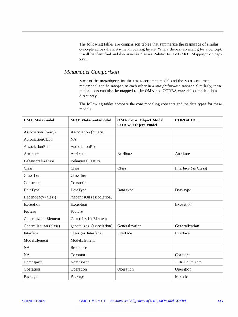
The following tables are comparison tables that summarize the mappings of similar concepts across the meta-metamodeling layers. Where there is no analog for a concept, it will be identified and discussed in ”Issues Related to UML-MOF Mapping” on page xxvi..
Metamodel Comparison
Most of the metaobjects for the UML core metamodel and the MOF core meta-metamodel can be mapped to each other in a straightforward manner. Similarly, these metaobjects can also be mapped to the OMA and CORBA core object models in a direct way.
The following tables compare the core modeling concepts and the data types for these models.
UML Metamodel MOF Meta-metamodel OMA Core Object Model CORBA Object Model
CORBA IDL
Association (n-ary) Association (binary)
AssociationClass NA
AssociationEnd AssociationEnd
Attribute Attribute Attribute Attribute
BehavioralFeature BehavioralFeature
Class Class Class Interface (as Class)
Classifier Classifier
Constraint Constraint
DataType DataType Data type Data type
Dependency (class) /dependsOn (association)
Exception Exception Exception
Feature Feature
GeneralizableElement GeneralizableElement
Generalization (class) generalizes (association) Generalization Generalization
Interface Class (as Interface) Interface Interface
ModelElement ModelElement
NA Reference
NA Constant Constant
Namespace Namespace ~ IR Containers
Operation Operation Operation Operation
Package Package Module
September 2001 OMG-UML, v 1.4 Architectural Alignment of UML, MOF, and CORBA xxv
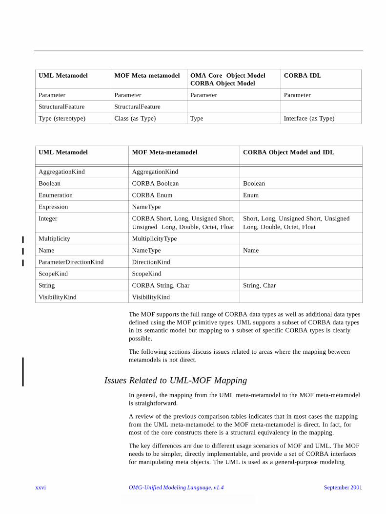
The MOF supports the full range of CORBA data types as well as additional data types defined using the MOF primitive types. UML supports a subset of CORBA data types in its semantic model but mapping to a subset of specific CORBA types is clearly possible.
The following sections discuss issues related to areas where the mapping between metamodels is not direct.
Issues Related to UML-MOF Mapping
In general, the mapping from the UML meta-metamodel to the MOF meta-metamodel is straightforward.
A review of the previous comparison tables indicates that in most cases the mapping from the UML meta-metamodel to the MOF meta-metamodel is direct. In fact, for most of the core constructs there is a structural equivalency in the mapping.
The key differences are due to different usage scenarios of MOF and UML. The MOF needs to be simpler, directly implementable, and provide a set of CORBA interfaces for manipulating meta objects. The UML is used as a general-purpose modeling
Parameter Parameter Parameter Parameter
StructuralFeature StructuralFeature
Type (stereotype) Class (as Type) Type Interface (as Type)
UML Metamodel MOF Meta-metamodel CORBA Object Model and IDL
AggregationKind AggregationKind
Boolean CORBA Boolean Boolean
Enumeration CORBA Enum Enum
Expression NameType
Integer CORBA Short, Long, Unsigned Short, Unsigned Long, Double, Octet, Float
Short, Long, Unsigned Short, Unsigned Long, Double, Octet, Float
Multiplicity MultiplicityType
Name NameType Name
ParameterDirectionKind DirectionKind
ScopeKind ScopeKind
String CORBA String, Char String, Char
VisibilityKind VisibilityKind
UML Metamodel MOF Meta-metamodel OMA Core Object Model CORBA Object Model
CORBA IDL
xxvi OMG-Unified Modeling Language, v1.4 September 2001
language, with potentially many implementation targets. These differences are commonly observed in repository, meta-CASE, and modeling-tool implementations. The key differences are:
• The MOF only supports binary associations while UML supports higher-order (also referred to as 'N-ary') associations. This tradeoff was made because N-ary relationships are rarely used in metamodeling and the design goal was to keep the MOF interfaces simpler. We have anticipated extending the MOF to support higher order associations in future.
• Associations in the MOF are limited to simple associations and cannot contain features. Association Classes in UML can contain features (such as attributes). The MOF has been defined to be structurally extensible to full-blown association classes in the future by relaxing this constraint. UML Association Classes are modeled as MOF Classes with well-defined multiplicity constraints to ensure shared lifetime of features owned by the association.
• The MOF supports the concept of a Reference which allows direct navigation from one Classifier to another. The UML metamodel uses the Target AssociationEnd’s 'name' property as a ‘pseudo-attribute’ for the same purpose, but navigates to another classifier through an Association. The concept of reference is widely used in object repositories, as well as object and object-relational databases and optimizes navigation across a metamodel.
• Some concepts such as Generalization, Dependency, and Refinement are reified as classes in UML, but implemented as Associations in the MOF. The MOF does not require the richness of UML in these areas.
• The MOF supports the full set of CORBA data types, whereas the UML metamodel does not define data types to this depth. A CORBA-specific implementation of UML is clearly possible by either creating the additional data types needed or by providing appropriate mappings.
• The UML has clearly defined the similarities of the key concepts of Class, Interface, and Type. The MOF and UML both use the Class concept as the most general of these in their respective models. The MOF specification is focused only on specification of metamodels and generation of CORBA interfaces; therefore, it does not deal with implementation concepts such as 'Methods.' UML clearly needs to support these concepts because UML can be used to model conceptual, logical, and implementation models. In this sense, the MOF uses the Class concept to define Types, since MOF Classes do not have any methods, just operations. This is consistent with the definition of UML Type as a stereotype of Class with a constraint that Types cannot contain methods. The MOF Class concept is rich enough to define Interfaces, and in fact the MOF specification itself clearly shows that an MOF Class can be mapped to multiple CORBA Interfaces.
The previous table shows that the mapping of metadatatypes between the meta-metamodels is also straightforward. Here also there are more MOF meta-metaobjects than there are UML meta-metaobjects. The MOF supports the full range of CORBA data types as well as additional data types defined using the MOF primitive types. UML supports a subset of CORBA data types in its semantic model but maps to specific CORBA types in its corresponding interface model.
September 2001 OMG-UML, v 1.4 Architectural Alignment of UML, MOF, and CORBA xxvii
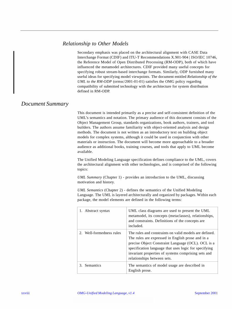
Relationship to Other Models
Secondary emphasis was placed on the architectural alignment with CASE Data Interchange Format (CDIF) and ITU-T Recommendations X.901-904 | ISO/IEC 10746, the Reference Model of Open Distributed Processing (RM-ODP), both of which have influenced the metamodel architectures. CDIF provided many useful concepts for specifying robust stream-based interchange formats. Similarly, ODP furnished many useful ideas for specifying model viewpoints. The document entitled Relationship of the UML to the RM-ODP (ormsc/2001-01-01) satisfies the OMG policy regarding compatibility of submitted technology with the architecture for system distribution defined in RM-ODP.
Document Summary
This document is intended primarily as a precise and self-consistent definition of the UML’s semantics and notation. The primary audience of this document consists of the Object Management Group, standards organizations, book authors, trainers, and tool builders. The authors assume familiarity with object-oriented analysis and design methods. The document is not written as an introductory text on building object models for complex systems, although it could be used in conjunction with other materials or instruction. The document will become more approachable to a broader audience as additional books, training courses, and tools that apply to UML become available.
The Unified Modeling Language specification defines compliance to the UML, covers the architectural alignment with other technologies, and is comprised of the following topics:
UML Summary (Chapter 1) - provides an introduction to the UML, discussing motivation and history.
UML Semantics (Chapter 2) - defines the semantics of the Unified Modeling Language. The UML is layered architecturally and organized by packages. Within each package, the model elements are defined in the following terms:
1. Abstract syntax UML class diagrams are used to present the UML metamodel, its concepts (metaclasses), relationships, and constraints. Definitions of the concepts are included.
2. Well-formedness rules The rules and constraints on valid models are defined. The rules are expressed in English prose and in a precise Object Constraint Language (OCL). OCL is a specification language that uses logic for specifying invariant properties of systems comprising sets and relationships between sets.
3. Semantics The semantics of model usage are described in English prose.
xxviii OMG-Unified Modeling Language, v1.4 September 2001
UML Notation Guide (Chapter 3) - specifies the graphic syntax for expressing the semantics described by the UML metamodel. Consequently, the UML Notation Guide’s chapter should be read in conjunction with the UML Semantics chapter.
UML Example Profiles (Chapter 4) - shows two example profiles, the UML Profile for Software Development Processes and the UML Profile for Business Modeling.
UML Model Interchange (Chapter 5) - specifies the how UML models can be interchanged using XML Metadata Interchange (XMI) and CORBA IDL.
Object Constraint Language Specification (Chapter 6) - defines the Object Constraint Language (OCL) syntax, semantics, and grammar. All OCL features are described in terms of concepts defined in the UML Semantics.
In addition, there is an appendix of Standard Elements that defines standard stereotypes, constraints, and tagged values for UML, and a glossary of terms.
Dependencies Between Chapters
UML Semantics (Chapter 2) can stand on its own, relative to the others, with the exception of the OCL Specification. The semantics depends upon OCL for the specification of its well-formedness rules.
The UML Notation Guide and UML Model Interchange both depend on the UML Semantics. Specifying these separately permits their evolution in the most flexible way, even though they are not completely independent.
The specifications in the UML Extensions chapter depend on both the notation and semantics chapters.
September 2001 OMG-UML, v 1.4 Document Summary xxix
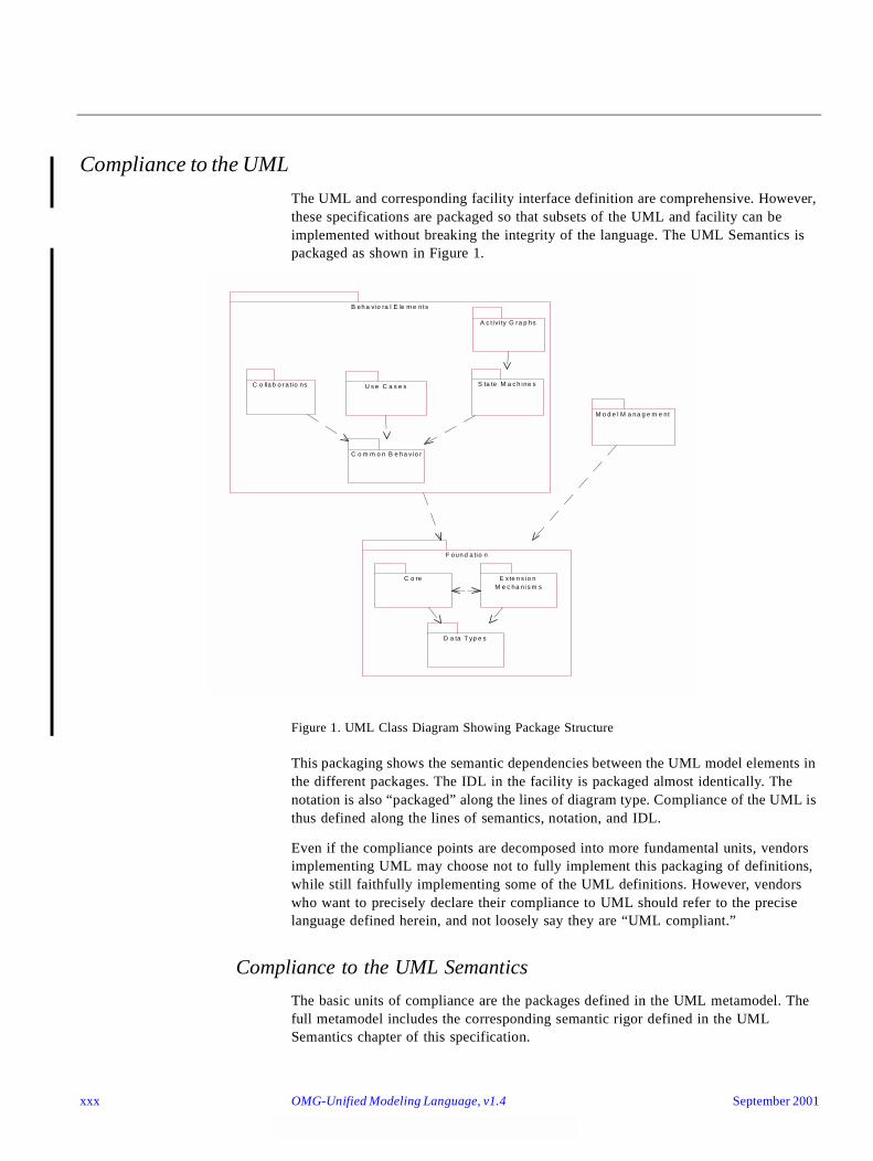
Compliance to the UML
The UML and corresponding facility interface definition are comprehensive. However, these specifications are packaged so that subsets of the UML and facility can be implemented without breaking the integrity of the language. The UML Semantics is packaged as shown in Figure 1.
Figure 1. UML Class Diagram Showing Package Structure
This packaging shows the semantic dependencies between the UML model elements in the different packages. The IDL in the facility is packaged almost identically. The notation is also “packaged” along the lines of diagram type. Compliance of the UML is thus defined along the lines of semantics, notation, and IDL.
Even if the compliance points are decomposed into more fundamental units, vendors implementing UML may choose not to fully implement this packaging of definitions, while still faithfully implementing some of the UML definitions. However, vendors who want to precisely declare their compliance to UML should refer to the precise language defined herein, and not loosely say they are “UML compliant.”
Compliance to the UML Semantics
The basic units of compliance are the packages defined in the UML metamodel. The full metamodel includes the corresponding semantic rigor defined in the UML Semantics chapter of this specification.
F oun d a tio n
B eh a vio ra l E le m e nts
M o d e l M a na g e m e nt
U s e C a s e s S ta te M a c h ine sC o lla b o r a tio ns
C o m m o n B e ha vio r
A c t iv i ty G ra p hs
C o re
D a ta T yp e s
E xte n s io n M e c ha ni s m s
xxx OMG-Unified Modeling Language, v1.4 September 2001
The class diagram illustrates the package dependencies, which are also summarized in the table below.
Complying with a package requires complying with the prerequisite package.
The semantics are defined in an implementation language-independent way. An implementation of the semantics, without consistent interface and implementation choices, does not guarantee tool interoperability. See Chapter 5, “UML Model Interchange.”
In addition to the above packages, compliance to a given metamodel package must load or know about the predefined UML standard elements (i.e., values for all predefined stereotypes, tags, and constraints). These are defined throughout the semantics and notation documents and summarized in the UML Standard Elements appendix. The predefined constraint values must be enforced consistent with their definitions. Having tools know about the standard elements is necessary for the full language and to avoid the definition of user-defined elements that conflict with the standard UML elements. Compliance to the UML Standard Elements and UML Standard Profiles is distinct from the UML Semantics, so not all tools need to know about the UML Standard Elements and UML Standard Profiles.
For any implementation of UML, it is optional that the tool implements the Object Constraint Language. A vendor conforming to OCL support must support the following:
• Validate and store syntactically correct OCL expressions as values for UML data types.
• Be able to perform a full type check on the object constraint expression. This check will test whether all features used in the expression are actually defined in the UML model and used correctly.
All tools conforming to the UML semantics are expected to conform to the following aspects of the semantics:
Package Prerequisite Packages
DataTypes
Core DataTypes, Extension Mechanisms
Extension Mechanisms Core, DataTypes
Common Behavior Foundation
State Machines Common Behavior, Foundation
Activity Graphs State Machines, Foundation
Collaborations Common Behavior, Foundation
Use Cases Common Behavior, Foundation
Model Management Foundation
September 2001 OMG-UML, v 1.4 Compliance to the UML xxxi
• abstract syntax; that is, the concepts, valid relationships, and constraints expressed in the corresponding class diagrams,
• well-formedness rules, and
• semantics of model usage.
However, vendors are expected to apply some discretion on how strictly the well-formedness rules are enforced. Tools should be able to report on well-formedness violations, but not necessarily force all models to be well formed. Incomplete models are common during certain phases of the development lifecycle, so they should be permitted.
Compliance to the UML Notation
The UML notation is an essential element of the UML to enable communication between team members. Compliance to the notation is optional, but the semantics are not very meaningful without a consistent way of expressing them.
Notation compliance is defined along the lines of the UML Diagrams types: use case, class, statechart, activity graph, sequence, collaboration, component, and deployment diagrams.
If the notation is implemented, a tool must enforce the underlying semantics and maintain consistency between diagrams if the diagrams share the same underlying model. By this definition, a simple “drawing tool” cannot be compliant to the UML notation.
There are many optional notation adornments. For example, a richly adorned class icon may include an embedded stereotype icon, a list of properties (tagged values and metamodel attributes), constraint expressions, attributes with visibilities indicated, and operations with full signatures. Complying with class diagram support implies the ability to support all of the associated adornments.
Compliance to the notation in the UML Standard Profiles is described separately.
Compliance to Model Interchange Using XMI
The UML XMI DTD (document number ad/01-02-16) supports all packages of the UML Interchange Metamodel, which is a MOF translation of the UML Semantics Metamodel. See Model Interchange Using XMI (section 5.2). Each package of the Interchange Metamodel defines a separate compliance option.
Compliance to Model Interchange Using CORBA IDL
A UML CORBAfacility must support the MOF Reflective interfaces. Supporting the reflective interfaces for the Core package is the most basic level of compliance.Support for each additional package is a separate compliance option. In addition, support for each package's specific IDL module defined in UML_1.4_CORBA_IDL.zip (document number ad/01-02-17) constitutes a separate compliance option.
xxxii OMG-Unified Modeling Language, v1.4 September 2001
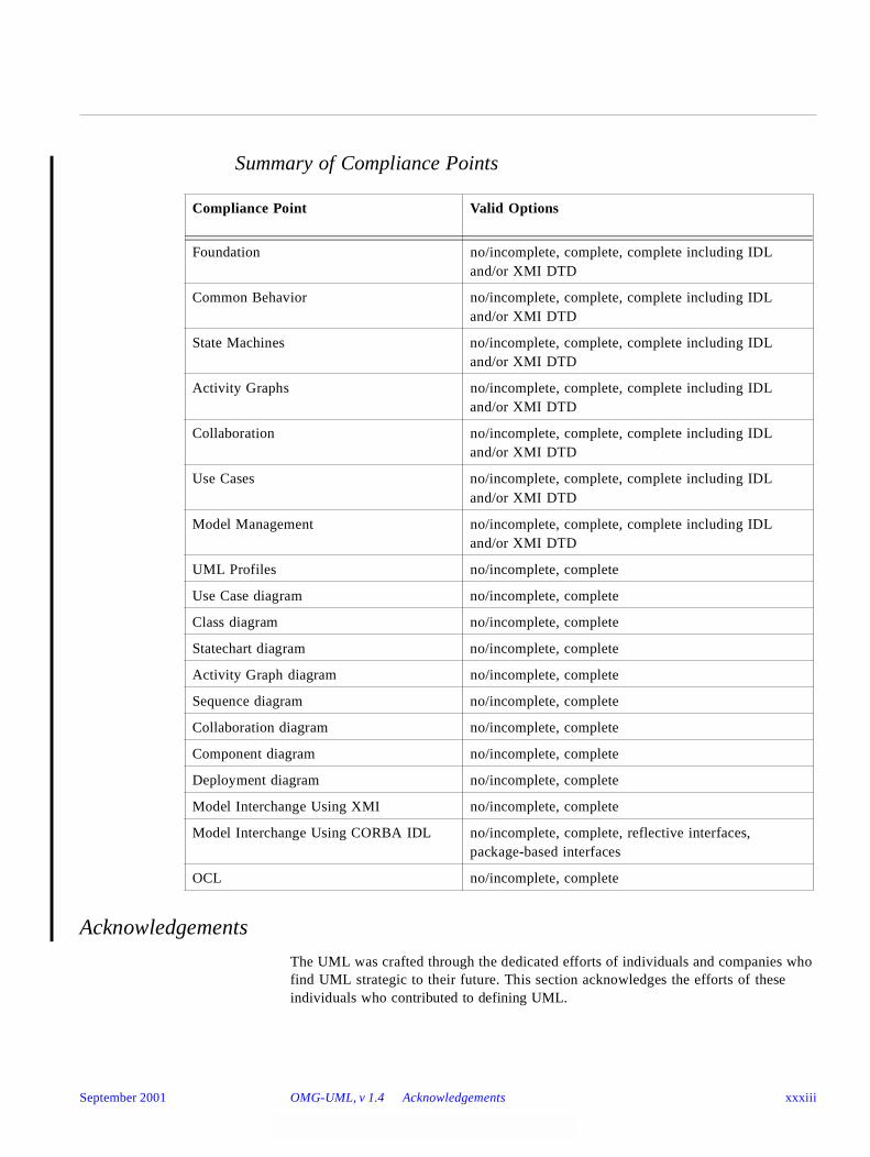
Summary of Compliance Points
Acknowledgements
The UML was crafted through the dedicated efforts of individuals and companies who find UML strategic to their future. This section acknowledges the efforts of these individuals who contributed to defining UML.
Compliance Point Valid Options
Foundation no/incomplete, complete, complete including IDL and/or XMI DTD
Common Behavior no/incomplete, complete, complete including IDL and/or XMI DTD
State Machines no/incomplete, complete, complete including IDL and/or XMI DTD
Activity Graphs no/incomplete, complete, complete including IDL and/or XMI DTD
Collaboration no/incomplete, complete, complete including IDL and/or XMI DTD
Use Cases no/incomplete, complete, complete including IDL and/or XMI DTD
Model Management no/incomplete, complete, complete including IDL and/or XMI DTD
UML Profiles no/incomplete, complete
Use Case diagram no/incomplete, complete
Class diagram no/incomplete, complete
Statechart diagram no/incomplete, complete
Activity Graph diagram no/incomplete, complete
Sequence diagram no/incomplete, complete
Collaboration diagram no/incomplete, complete
Component diagram no/incomplete, complete
Deployment diagram no/incomplete, complete
Model Interchange Using XMI no/incomplete, complete
Model Interchange Using CORBA IDL no/incomplete, complete, reflective interfaces, package-based interfaces
OCL no/incomplete, complete
September 2001 OMG-UML, v 1.4 Acknowledgements xxxiii

UML Core Team
The following persons were members of the core development team for the UML proposal or served on the first or second UML Revision Task Force:
• Colorado State University: Robert France
• Computer Associates: John Clark
• Concept 5 Technologies: Ed Seidewitz
• Data Access Corporation: Tom Digre
• Enea Data: Karin Palmkvist
• Hewlett-Packard Company: Martin Griss
• IBM Corporation: Steve Brodsky, Steve Cook
• I-Logix: Eran Gery, David Harel
• ICON Computing: Desmond D’Souza
• IntelliCorp and James Martin & Co.: James Odell
• Kabira Technologies: Conrad Bock
• Klasse Objecten: Jos Warmer
• MCI Systemhouse: Joaquin Miller
• OAO Technology Solutions: Ed Seidewitz
• ObjecTime Limited: John Hogg, Bran Selic
• Oracle Corporation: Guus Ramackers
• PLATINUM Technology Inc.: Dilhar DeSilva
• Rational Software: Grady Booch, Ed Eykholt, Ivar Jacobson, Gunnar Overgaard, Jim Rumbaugh
• SAP: Oliver Wiegert
• SOFTEAM: Philippe Desfray
• Sterling Software: John Cheesman, Keith Short
• Sun Microsystems: Peter Walker
• Telelogic: Cris Kobryn, Morgan Björkander
• Taskon: Trygve Reenskaug
• Unisys Corporation: Sridhar Iyengar, GK Khalsa, Don Baisley
UML 1.1 Semantics Task Force
During the final submission phase for UML 1.1, a team was formed to focus on improving the formality of the UML 1.0 semantics, as well as incorporating additional ideas from the partners. Under the leadership of Cris Kobryn, this team was very instrumental in reconciling diverse viewpoints into a consistent set of semantics, as expressed in the revised UML Semantics. Other members of this team were Dilhar DeSilva, Martin Griss, Sridhar Iyengar, Eran Gery, James Odell, Gunnar Overgaard, Karin Palmkvist, Guus Ramackers, Bran Selic, and Jos Warmer. Grady Booch, Ivar Jacobson, and Jim Rumbaugh also provided their expertise to the team.
xxxiv OMG-Unified Modeling Language, v1.4 September 2001
UML Revision Task Force
After the adoption of the UML 1.1 proposal by the OMG membership in November, 1997, the OMG chartered a revision task force (RTF) to deal with bugs, inconsistencies, and other problems that could be handled without greatly expanding the scope of the original proposal. The RTF accepted public comments submitted to the OMG after adoption of the proposal. This document containing UML version 1.3 is the result of the work of the UML RTF. The results have been issued in several preliminary versions with minor changes expected in the final version. If you have a preliminary version of the specification, you can obtain an updated version from the OMG web site at www.omg.org.
Contributors and Supporters
We also acknowledge the contributions, influence, and support of the following individuals.
Jim Amsden, Hernan Astudillo, Colin Atkinson, Dave Bernstein, Philip A. Bernstein, Michael Blaha, Mike Bradley, Ray Buhr, Gary Cernosek, James Cerrato, Brian Cook, Magnus Christerson, Dai Clegg, Peter Coad, Derek Coleman, Ward Cunningham, Raj Datta, Mike Devlin, Philippe Desfray, Bruce Douglass, Nathan Dykman, Staffan Ehnebom, Maria Ericsson, Johannes Ernst, Don Firesmith, Martin Fowler, Adam Frankl, Eric Gamma, Dipayan Gangopadhyay, Garth Gullekson, Rick Hargrove, Tim Harrison, Richard Helm, Brian Henderson-Sellers, Michael Hirsch, Bob Hodges, Glenn Hollowell, Yves Holvoet, Jon Hopkins, John Hsia, Anders Ivner, Ralph Johnson, Stuart Kent, Anneke Kleppe, Philippe Kruchten, Paul Kyzivat, Martin Lang, Grant Larsen, Reed Letsinger, Mary Loomis, Jeff MacKay, Bev Macmaster, Robert Martin, Terrie McDaniel, Jim McGee, Bertrand Meyer, Mike Meier, Randy Messer, Greg Meyers, Fred Mol, Birger Moller-Pedersen, Luis Montero, Paul Moskowitz, Andy Moss, Jan Pachl, Paul Patrick, Woody Pidcock, Bill Premerlani, Jeff Price, Jerri Pries, Terry Quatrani, Mats Rahm, George Reich, Rich Reitman, Rudolf M. Riess, Erick Rivas, Kenny Rubin, Bernhard Rumpe, Jim Rye, Danny Sabbah, Tom Schultz, Gregson Siu, Jeff Sutherland, Dan Tasker, Dave Tropeano, Andy Trice, Dan Uhlar, John Vlissides, Larry Wall, Paul Ward, Diane White, Oliver Wiegert, Alan Wills, Rebecca Wirfs-Brock, Bryan Wood, Ed Yourdon, and Steve Zeigler.
September 2001 OMG-UML, v 1.4 Acknowledgements xxxv
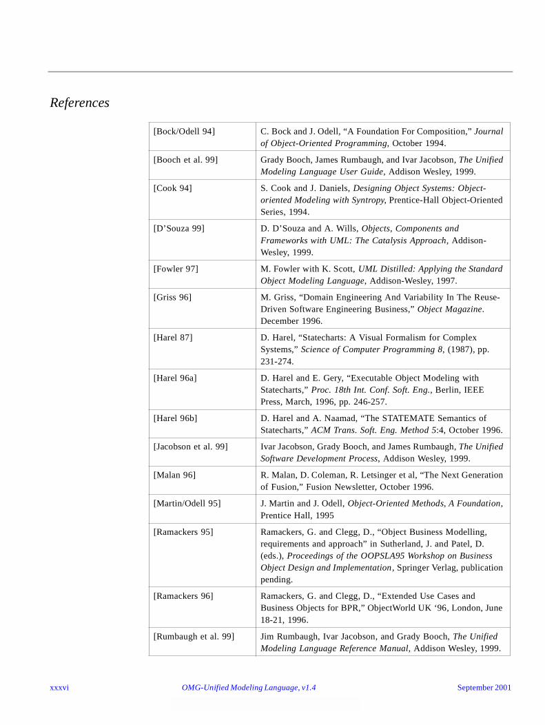
References
[Bock/Odell 94] C. Bock and J. Odell, “A Foundation For Composition,” Journal of Object-Oriented Programming, October 1994.
[Booch et al. 99] Grady Booch, James Rumbaugh, and Ivar Jacobson, The Unified Modeling Language User Guide, Addison Wesley, 1999.
[Cook 94] S. Cook and J. Daniels, Designing Object Systems: Object-oriented Modeling with Syntropy, Prentice-Hall Object-Oriented Series, 1994.
[D’Souza 99] D. D’Souza and A. Wills, Objects, Components and Frameworks with UML: The Catalysis Approach, Addison-Wesley, 1999.
[Fowler 97] M. Fowler with K. Scott, UML Distilled: Applying the Standard Object Modeling Language, Addison-Wesley, 1997.
[Griss 96] M. Griss, “Domain Engineering And Variability In The Reuse-Driven Software Engineering Business,” Object Magazine. December 1996.
[Harel 87] D. Harel, “Statecharts: A Visual Formalism for Complex Systems,” Science of Computer Programming 8, (1987), pp. 231-274.
[Harel 96a] D. Harel and E. Gery, “Executable Object Modeling with Statecharts,” Proc. 18th Int. Conf. Soft. Eng., Berlin, IEEE Press, March, 1996, pp. 246-257.
[Harel 96b] D. Harel and A. Naamad, “The STATEMATE Semantics of Statecharts,” ACM Trans. Soft. Eng. Method 5:4, October 1996.
[Jacobson et al. 99] Ivar Jacobson, Grady Booch, and James Rumbaugh, The Unified Software Development Process, Addison Wesley, 1999.
[Malan 96] R. Malan, D. Coleman, R. Letsinger et al, “The Next Generation of Fusion,” Fusion Newsletter, October 1996.
[Martin/Odell 95] J. Martin and J. Odell, Object-Oriented Methods, A Foundation, Prentice Hall, 1995
[Ramackers 95] Ramackers, G. and Clegg, D., “Object Business Modelling, requirements and approach” in Sutherland, J. and Patel, D. (eds.), Proceedings of the OOPSLA95 Workshop on Business Object Design and Implementation , Springer Verlag, publication pending.
[Ramackers 96] Ramackers, G. and Clegg, D., “Extended Use Cases and Business Objects for BPR,” ObjectWorld UK ‘96, London, June 18-21, 1996.
[Rumbaugh et al. 99] Jim Rumbaugh, Ivar Jacobson, and Grady Booch, The Unified Modeling Language Reference Manual, Addison Wesley, 1999.
xxxvi OMG-Unified Modeling Language, v1.4 September 2001
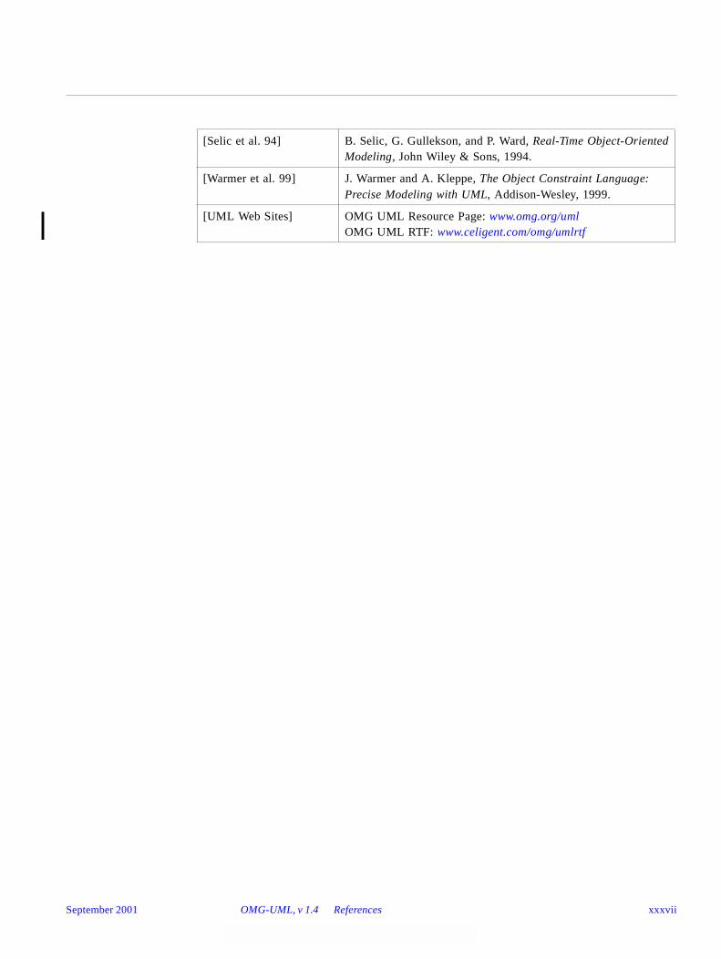
[Selic et al. 94] B. Selic, G. Gullekson, and P. Ward, Real-Time Object-OrientedModeling, John Wiley & Sons, 1994.
[Warmer et al. 99] J. Warmer and A. Kleppe, The Object Constraint Language: Precise Modeling with UML, Addison-Wesley, 1999.
[UML Web Sites] OMG UML Resource Page: www.omg.org/umlOMG UML RTF: www.celigent.com/omg/umlrtf
September 2001 OMG-UML, v 1.4 References xxxvii

xxxviii OMG-Unified Modeling Language, v1.4 September 2001
UML Summary 1
The UML Summary provides an introduction to the UML, discussing its motivation and history.
Contents
This chapter contains the following topics.
1.1 Overview
The Unified Modeling Language (UML) is a language for specifying, visualizing, constructing, and documenting the artifacts of software systems, as well as for business modeling and other non-software systems. The UML represents a collection of the best engineering practices that have proven successful in the modeling of large and complex systems.
Topic Page
“Overview” 1-1
“Primary Artifacts of the UML” 1-2
“Motivation to Define the UML” 1-3
“Goals of the UML” 1-4
“Scope of the UML” 1-6
“UML - Past, Present, and Future” 1-11
September 2001 OMG-Unified Modeling Language, v1.4 1-1
1
1.2Primary Artifacts of the UML
What are the primary artifacts of the UML? This can be answered from two different perspectives: the UML definition itself and how it is used to produce project artifacts.
1.2.1 UML-defining Artifacts
To aid the understanding of the artifacts that constitute the Unified Modeling Language itself, this document consists of chapters describing UML Semantics, UML Notation Guide, and UML Standard Profiles.
1.2.2 Development Project Artifacts
The choice of what models and diagrams one creates has a profound influence upon how a problem is attacked and how a corresponding solution is shaped. Abstraction, the focus on relevant details while ignoring others, is a key to learning and communicating. Because of this:
• Every complex system is best approached through a small set of nearly independent views of a model. No single view is sufficient.
• Every model may be expressed at different levels of fidelity.
• The best models are connected to reality.
In terms of the views of a model, the UML defines the following graphical diagrams:
• use case diagram
• class diagram
• behavior diagrams:
• statechart diagram
• activity diagram
• interaction diagrams:
• sequence diagram
• collaboration diagram
• implementation diagrams:
• component diagram
• deployment diagram
Although other names are sometimes given to these diagrams, this list constitutes the canonical diagram names.
These diagrams provide multiple perspectives of the system under analysis or development. The underlying model integrates these perspectives so that a self-consistent system can be analyzed and built. These diagrams, along with supporting documentation, are the primary artifacts that a modeler sees, although the UML and supporting tools will provide for a number of derivative views. These diagrams are further described in the UML Notation Guide (Chapter 3 of this specification).
1-2 OMG-Unified Modeling Language, v1.4 September 2001
1
A frequently asked question has been: Why doesn’t UML support data-flow diagrams? Simply put, data-flow and other diagram types that were not included in the UML do not fit as cleanly into a consistent object-oriented paradigm. Activity diagrams and collaboration diagrams accomplish much of what people want from DFDs, and then some. Activity diagrams are also useful for modeling workflow.
1.3Motivation to Define the UML
This section describes several factors motivating the UML and includes why modeling is essential. It highlights a few key trends in the software industry and describes the issues caused by divergence of modeling approaches.
1.3.1 Why We Model
Developing a model for an industrial-strength software system prior to its construction or renovation is as essential as having a blueprint for large building. Good models are essential for communication among project teams and to assure architectural soundness. We build models of complex systems because we cannot comprehend any such system in its entirety. As the complexity of systems increase, so does the importance of good modeling techniques. There are many additional factors of a project’s success, but having a rigorous modeling language standard is one essential factor. A modeling language must include:
• Model elements — fundamental modeling concepts and semantics
• Notation — visual rendering of model elements
• Guidelines — idioms of usage within the trade
In the face of increasingly complex systems, visualization and modeling become essential. The UML is a well-defined and widely accepted response to that need. It is the visual modeling language of choice for building object-oriented and component-based systems.
1.3.2 Industry Trends in Software
As the strategic value of software increases for many companies, the industry looks for techniques to automate the production of software. We look for techniques to improve quality and reduce cost and time-to-market. These techniques include component technology, visual programming, patterns, and frameworks. We also seek techniques to manage the complexity of systems as they increase in scope and scale. In particular, we recognize the need to solve recurring architectural problems, such as physical distribution, concurrency, replication, security, load balancing, and fault tolerance. Development for the worldwide web makes some things simpler, but exacerbates these architectural problems.
Complexity will vary by application domain and process phase. One of the key motivations in the minds of the UML developers was to create a set of semantics and notation that adequately addresses all scales of architectural complexity, across all domains.
September 2001 OMG-UML , v1.4 Motivation to Define the UML 1-3
1
1.3.3 Prior to Industry Convergence
Prior to the UML, there was no clear leading modeling language. Users had to choose from among many similar modeling languages with minor differences in overall expressive power. Most of the modeling languages shared a set of commonly accepted concepts that are expressed slightly differently in various languages. This lack of agreement discouraged new users from entering the object technology market and from doing object modeling, without greatly expanding the power of modeling. Users longed for the industry to adopt one, or a very few, broadly supported modeling languages suitable for general-purpose usage.
Some vendors were discouraged from entering the object modeling area because of the need to support many similar, but slightly different, modeling languages. In particular, the supply of add-on tools has been depressed because small vendors cannot afford to support many different formats from many different front-end modeling tools. It is important to the entire object industry to encourage broadly based tools and vendors, as well as niche products that cater to the needs of specialized groups.
The perpetual cost of using and supporting many modeling languages motivated many companies producing or using object technology to endorse and support the development of the UML.
While the UML does not guarantee project success, it does improve many things. For example, it significantly lowers the perpetual cost of training and retooling when changing between projects or organizations. It provides the opportunity for new integration between tools, processes, and domains. But most importantly, it enables developers to focus on delivering business value and gives them a paradigm to accomplish this.
1.4 Goals of the UML
The primary design goals of the UML are as follows:
• Provide users with a ready-to-use, expressive visual modeling language to develop and exchange meaningful models.
• Furnish extensibility and specialization mechanisms to extend the core concepts.
• Support specifications that are independent of particular programming languages and development processes.
• Provide a formal basis for understanding the modeling language.
• Encourage the growth of the object tools market.
• Support higher-level development concepts such as components, collaborations, frameworks and patterns.
• Integrate best practices.
These goals are discussed in detail below.
1-4 OMG-Unified Modeling Language, v1.4 September 2001

1
Provide users with a ready-to-use, expressive visual modeling language to develop and exchange meaningful models
It is important that the Object Analysis and Design (OA&D) standard supports a modeling language that can be used “out of the box” to do normal general-purpose modeling tasks. If the standard merely provides a meta-meta-description that requires tailoring to a particular set of modeling concepts, then it will not achieve the purpose of allowing users to exchange models without losing information or without imposing excessive work to map their models to a very abstract form. The UML consolidates a set of core modeling concepts that are generally accepted across many current methods and modeling tools. These concepts are needed in many or most large applications, although not every concept is needed in every part of every application. Specifying a meta-meta-level format for the concepts is not sufficient for model users, because the concepts must be made concrete for real modeling to occur. If the concepts in different application areas were substantially different, then such an approach might work, but the core concepts needed by most application areas are similar and should be supported directly by the standard without the need for another layer.
Furnish extensibility and specialization mechanisms to extend the core concepts
OMG expects that the UML will be tailored as new needs are discovered and for specific domains. At the same time, we do not want to force the common core concepts to be redefined or re-implemented for each tailored area. Therefore, we believe that the extension mechanisms should support deviations from the common case, rather than being required to implement the core modeling concepts themselves. The core concepts should not be changed more than necessary. Users need to be able to
• build models using core concepts without using extension mechanisms for most normal applications,
• add new concepts and notations for issues not covered by the core,
• choose among variant interpretations of existing concepts, when there is no clear consensus, and
• specialize the concepts, notations, and constraints for particular application domains.
Support specifications that are independent of particular programming languages and development processes
The UML must and can support all reasonable programming languages. It also must and can support various methods and processes of building models. The UML can support multiple programming languages and development methods without excessive difficulty.
Provide a formal basis for understanding the modeling language
Because users will use formality to help understand the language, it must be both precise and approachable; a lack of either dimension damages its usefulness. The formalisms must not require excessive levels of indirection or layering, use of low-level mathematical notations distant from the modeling domain, such as set-theoretic notation, or operational definitions that are equivalent to programming an
September 2001 OMG-UML , v1.4 Goals of the UML 1-5
1
implementation. The UML provides a formal definition of the static format of the model using a metamodel expressed in UML class diagrams. This is a popular and widely accepted formal approach for specifying the format of a model and directly leads to the implementation of interchange formats. UML expresses well-formedness constraints in precise natural language plus Object Constraint Language expressions. UML expresses the operational meaning of most constructs in precise natural language. The fully formal approach taken to specify languages such as Algol-68 was not approachable enough for most practical usage.
Encourage the growth of the object tools market
By enabling vendors to support a standard modeling language used by most users and tools, the industry benefits. While vendors still can add value in their tool implementations, enabling interoperability is essential. Interoperability requires that models can be exchanged among users and tools without loss of information. This can only occur if the tools agree on the format and meaning of all of the relevant concepts. Using a higher meta-level is no solution unless the mapping to the user-level concepts is included in the standard.
Support higher-level development concepts such as components, collaborations, frameworks, and patterns
Clearly defined semantics of these concepts is essential to reap the full benefit of object-orientation and reuse. Defining these within the holistic context of a modeling language is a unique contribution of the UML.
Integrate best practices
A key motivation behind the development of the UML has been to integrate the best practices in the industry, encompassing widely varying views based on levels of abstraction, domains, architectures, life cycle stages, implementation technologies, etc. The UML is indeed such an integration of best practices.
1.5Scope of the UML
The Unified Modeling Language (UML) is a language for specifying, constructing, visualizing, and documenting the artifacts of a software-intensive system.
First and foremost, the Unified Modeling Language fuses the concepts of Booch, OMT, and OOSE. The result is a single, common, and widely usable modeling language for users of these and other methods.
Second, the Unified Modeling Language pushes the envelope of what can be done with existing methods. As an example, the UML authors targeted the modeling of concurrent, distributed systems to assure the UML adequately addresses these domains.
Third, the Unified Modeling Language focuses on a standard modeling language, not a standard process. Although the UML must be applied in the context of a process, it is our experience that different organizations and problem domains require different processes. (For example, the development process for shrink-wrapped software is an interesting one, but building shrink-wrapped software is vastly different from building
1-6 OMG-Unified Modeling Language, v1.4 September 2001
1
hard-real-time avionics systems upon which lives depend.) Therefore, the efforts concentrated first on a common metamodel (which unifies semantics) and second on a common notation (which provides a human rendering of these semantics). The UML authors promote a development process that is use-case driven, architecture centric, and iterative and incremental.
The UML specifies a modeling language that incorporates the object-oriented community’s consensus on core modeling concepts. It allows deviations to be expressed in terms of its extension mechanisms. The Unified Modeling Language provides the following:
• Semantics and notation to address a wide variety of contemporary modeling issues in a direct and economical fashion.
• Semantics to address certain expected future modeling issues, specifically related to component technology, distributed computing, frameworks, and executability.
• Extensibility mechanisms so individual projects can extend the metamodel for their application at low cost. We don’t want users to directly change the UML metamodel.
• Extensibility mechanisms so that future modeling approaches could be grown on top of the UML.
• Semantics to facilitate model interchange among a variety of tools.
• Semantics to specify the interface to repositories for the sharing and storage of model artifacts.
1.5.1 Outside the Scope of the UML
1.5.1.1 Programming Languages
The UML, a visual modeling language, is not intended to be a visual programming language, in the sense of having all the necessary visual and semantic support to replace programming languages. The UML is a language for visualizing, specifying, constructing, and documenting the artifacts of a software-intensive system, but it does draw the line as you move toward code. For example, complex branches and joins are better expressed in a textual programming language. The UML does have a tight mapping to a family of object languages so that you can get the best of both worlds.
1.5.1.2 Tools
Standardizing a language is necessarily the foundation for tools and process. Tools and their interoperability are very dependent on a solid semantic and notation definition, such as the UML provides. The UML defines a semantic metamodel, not a tool interface, storage, or run-time model, although these should be fairly close to one another.
September 2001 OMG-UML , v1.4 Scope of the UML 1-7

1
The UML documents do include some tips to tool vendors on implementation choices, but do not address everything needed. For example, they don’t address topics like diagram coloring, user navigation, animation, storage/implementation models, or other features.
1.5.1.3 Process
Many organizations will use the UML as a common language for its project artifacts, but will use the same UML diagram types in the context of different processes. The UML is intentionally process independent, and defining a standard process was not a goal of the UML or OMG’s RFP.
The UML authors do recognize the importance of process. The presence of a well-defined and well-managed process is often a key discriminator between hyperproductive projects and unsuccessful ones. The reliance upon heroic programming is not a sustainable business practice. A process
• provides guidance as to the order of a team’s activities,
• specifies what artifacts should be developed,
• directs the tasks of individual developers and the team as a whole, and
• offers criteria for monitoring and measuring a project’s products and activities.
Processes by their very nature must be tailored to the organization, culture, and problem domain at hand. What works in one context (shrink-wrapped software development, for example) would be a disaster in another (hard-real-time, human-rated systems, for example). The selection of a particular process will vary greatly, depending on such things as problem domain, implementation technology, and skills of the team.
Booch, OMT, OOSE, and many other methods have well-defined processes, and the UML can support most methods. There has been some convergence on development process practices, but there is not yet consensus for standardization. What will likely result is general agreement on best practices and potentially the embracing of a process framework, within which individual processes can be instantiated. Although the UML does not mandate a process, its developers have recognized the value of a use-case driven, architecture-centric, iterative, and incremental process, so were careful to enable (but not require) this with the UML.
1.5.2 Comparing UML to Other Modeling Languages
It should be made clear that the Unified Modeling Language is not a radical departure from Booch, OMT, or OOSE, but rather the legitimate successor to all three. This means that if you are a Booch, OMT, or OOSE user today, your training, experience, and tools will be preserved, because the Unified Modeling Language is a natural evolutionary step. The UML will be equally easy to adopt for users of many other methods, but their authors must decide for themselves whether to embrace the UML concepts and notation underneath their methods.
1-8 OMG-Unified Modeling Language, v1.4 September 2001
1
The Unified Modeling Language is more expressive yet cleaner and more uniform than Booch, OMT, OOSE, and other methods. This means that there is value in moving to the Unified Modeling Language, because it will allow projects to model things they could not have done before. Users of most other methods and modeling languages will gain value by moving to the UML, since it removes the unnecessary differences in notation and terminology that obscure the underlying similarities of most of these approaches.
With respect to other visual modeling languages, including entity-relationship modeling, BPR flow charts, and state-driven languages, the UML should provide improved expressiveness and holistic integrity.
Users of existing methods will experience slight changes in notation, but this should not take much relearning and will bring a clarification of the underlying semantics. If the unification goals have been achieved, UML will be an obvious choice when beginning new projects, especially as the availability of tools, books, and training becomes widespread. Many visual modeling tools support existing notations, such as Booch, OMT, OOSE, or others, as views of an underlying model; when these tools add support for UML (as some already have) users will enjoy the benefit of switching their current models to the UML notation without loss of information.
Existing users of any object method can expect a fairly quick learning curve to achieve the same expressiveness as they previously knew. One can quickly learn and use the basics productively. More advanced techniques, such as the use of stereotypes and properties, will require some study since they enable very expressive and precise models needed only when the problem at hand requires them.
1.5.3 Features of the UML
The goals of the unification efforts were to keep it simple, to cast away elements of existing Booch, OMT, and OOSE that didn’t work in practice, to add elements from other methods that were more effective, and to invent new only when an existing solution was not available. Because the UML authors were in effect designing a language (albeit a graphical one), they had to strike a proper balance between minimalism (everything is text and boxes) and over-engineering (having an icon for every conceivable modeling element). To that end, they were very careful about adding new things, because they didn’t want to make the UML unnecessarily complex. Along the way, however, some things were found that were advantageous to add because they have proven useful in practice in other modeling.
There are several new concepts that are included in UML, including
• extensibility mechanisms (stereotypes, tagged values, and constraints),
• threads and processes,
• distribution and concurrency (e.g., for modeling ActiveX/DCOM and CORBA),
• patterns/collaborations,
• activity diagrams (for business process modeling),
• refinement (to handle relationships between levels of abstraction),
September 2001 OMG-UML , v1.4 Scope of the UML 1-9
1
• interfaces and components, and
• a constraint language.
Many of these ideas were present in various individual methods and theories but UML brings them together into a coherent whole. In addition to these major changes, there are many other localized improvements over the Booch, OMT, and OOSE semantics and notation.
The UML is an evolution from Booch, OMT, OOSE, other object-oriented methods, and many other sources. These various sources incorporated many different elements from many authors, including non-OO influences. The UML notation is a melding of graphical syntax from various sources, with a number of symbols removed (because they were confusing, superfluous, or little used) and with a few new symbols added. The ideas in the UML come from the community of ideas developed by many different people in the object-oriented field. The UML developers did not invent most of these ideas; rather, their role was to select and integrate the best ideas from object modeling and computer-science practices. The actual genealogy of the notation and underlying detailed semantics is complicated, so it is discussed here only to provide context, not to represent precise history.
Use-case diagrams are similar in appearance to those in OOSE.
Class diagrams are a melding of OMT, Booch, class diagrams of most other object methods. Stereotypes and their corresponding icons can be defined for various diagrams to support other modeling styles. Stereotypes, constraints, and taggedValues are concepts added in UML that did not previously exist in the major modeling languages.
Statechart diagrams are substantially based on the statecharts of David Harel with minor modifications. Activity graph diagrams, which share much of the same underlying semantics, are similar to the work flow diagrams developed by many sources including many pre-object sources.
Sequence diagrams were found in a variety of object methods under a variety of names (interaction, message trace, and event trace) and date to pre-object days. Collaboration diagrams were adapted from Booch (object diagram), Fusion (object interaction graph), and a number of other sources.
Collaborations are now first-class modeling entities, and often form the basis of patterns.
The implementation diagrams (component and deployment diagrams) are derived from Booch’s module and process diagrams, but they are now component-centered, rather than module-centered and are far better interconnected.
Stereotypes are one of the extension mechanisms and extend the semantics of the metamodel. User-defined icons can be associated with given stereotypes for tailoring the UML to specific processes.
1-10 OMG-Unified Modeling Language, v1.4 September 2001

1
Object Constraint Language is used by UML to specify the semantics and is provided as a language for expressions during modeling. OCL is an expression language having its root in the Syntropy method and has been influenced by expression languages in other methods like Catalysis. The informal navigation from OMT has the same intent, where OCL is formalized and more extensive.
Each of these concepts has further predecessors and many other influences. We realize that any brief list of influences is incomplete and we recognize that the UML is the product of a long history of ideas in the computer science and software engineering area.
1.6UML - Past, Present, and Future
The UML was developed by Rational Software and its partners. Many companies are incorporating the UML as a standard into their development process and products, which cover disciplines such as business modeling, requirements management, analysis & design, programming, and testing.
1.6.1 UML 0.8 - 0.91
1.6.1.1 Precursors to UML
Identifiable object-oriented modeling languages began to appear between mid-1970 and the late 1980s as various methodologists experimented with different approaches to object-oriented analysis and design. Several other techniques influenced these languages, including Entity-Relationship modeling, the Specification & Description Language (SDL, circa 1976, CCITT), and other techniques. The number of identified modeling languages increased from less than 10 to more than 50 during the period between 1989-1994. Many users of object methods had trouble finding complete satisfaction in any one modeling language, fueling the “method wars.” By the mid-1990s, new iterations of these methods began to appear, most notably Booch’93, the continued evolution of OMT, and Fusion. These methods began to incorporate each other’s techniques, and a few clearly prominent methods emerged, including the OOSE, OMT-2, and Booch’93 methods. Each of these was a complete method, and was recognized as having certain strengths. In simple terms, OOSE was a use-case oriented approach that provided excellent support business engineering and requirements analysis. OMT-2 was especially expressive for analysis and data-intensive information systems. Booch’93 was particularly expressive during design and construction phases of projects and popular for engineering-intensive applications.
1.6.1.2 Booch, Rumbaugh, and Jacobson Join Forces
The development of UML began in October of 1994 when Grady Booch and Jim Rumbaugh of Rational Software Corporation began their work on unifying the Booch and OMT (Object Modeling Technique) methods. Given that the Booch and OMT methods were already independently growing together and were collectively recognized as leading object-oriented methods worldwide, Booch and Rumbaugh joined forces to forge a complete unification of their work. A draft version 0.8 of the
September 2001 OMG-UML , v1.4 UML - Past, Present, and Future 1-11
1
Unified Method, as it was then called, was released in October of 1995. In the Fall of 1995, Ivar Jacobson and his Objectory company joined Rational and this unification effort, merging in the OOSE (Object-Oriented Software Engineering) method. The Objectory name is now used within Rational primarily to describe its UML-compliant process, the Rational Unified Process.
As the primary authors of the Booch, OMT, and OOSE methods, Grady Booch, Jim Rumbaugh, and Ivar Jacobson were motivated to create a unified modeling language for three reasons. First, these methods were already evolving toward each other independently. It made sense to continue that evolution together rather than apart, eliminating the potential for any unnecessary and gratuitous differences that would further confuse users. Second, by unifying the semantics and notation, they could bring some stability to the object-oriented marketplace, allowing projects to settle on one mature modeling language and letting tool builders focus on delivering more useful features. Third, they expected that their collaboration would yield improvements in all three earlier methods, helping them to capture lessons learned and to address problems that none of their methods previously handled well.
As they began their unification, they established four goals to focus their efforts:
1. Enable the modeling of systems (and not just software) using object-oriented concepts
2. Establish an explicit coupling to conceptual as well as executable artifacts
3. Address the issues of scale inherent in complex, mission-critical systems
4. Create a modeling language usable by both humans and machines
Devising a notation for use in object-oriented analysis and design is not unlike designing a programming language. There are tradeoffs. First, one must bound the problem: Should the notation encompass requirement specification? (Yes, partially.) Should the notation extend to the level of a visual programming language? (No.) Second, one must strike a balance between expressiveness and simplicity: Too simple a notation will limit the breadth of problems that can be solved; too complex a notation will overwhelm the mortal developer. In the case of unifying existing methods, one must also be sensitive to the installed base: Make too many changes, and you will confuse existing users. Resist advancing the notation, and you will miss the opportunity of engaging a much broader set of users. The UML definition strives to make the best tradeoffs in each of these areas.
The efforts of Booch, Rumbaugh, and Jacobson resulted in the release of the UML 0.9 and 0.91 documents in June and October of 1996. During 1996, the UML authors invited and received feedback from the general community. They incorporated this feedback, but it was clear that additional focused attention was still required.
1.6.2 UML Partners
During 1996, it became clear that several organizations saw UML as strategic to their business. A Request for Proposal (RFP) issued by the Object Management Group (OMG) provided the catalyst for these organizations to join forces around producing a
1-12 OMG-Unified Modeling Language, v1.4 September 2001

1
joint RFP response. Rational established the UML Partners consortium with several organizations willing to dedicate resources to work toward a strong UML definition. Those contributing most to the UML definition included: Digital Equipment Corp., HP, i-Logix, IntelliCorp, IBM, ICON Computing, MCI Systemhouse, Microsoft, Oracle, Rational Software, TI, and Unisys. This collaboration produced UML, a modeling language that was well defined, expressive, powerful, and generally applicable.
In January 1997 IBM & ObjecTime; Platinum Technology; Ptech; Taskon & Reich Technologies; and Softeam also submitted separate RFP responses to the OMG. These companies joined the UML partners to contribute their ideas, and together the partners produced the revised UML 1.1 response. The focus of the UML 1.1 release was to improve the clarity of the UML 1.0 semantics and to incorporate contributions from the new partners.
This document is based on the UML 1.1 release and is the result of a collaborative team effort. The UML Partners have worked hard as a team to define UML. While each partner came in with their own perspective and areas of interest, the result has benefited from each of them and from the diversity of their experiences. The UML Partners contributed a variety of expert perspectives, including, but not limited to, the following: OMG and RM-ODP technology perspectives, business modeling, constraint language, state machine semantics, types, interfaces, components, collaborations, refinement, frameworks, distribution, and metamodel.
1.6.3 UML - Present and Future
The UML is nonproprietary and open to all. It addresses the needs of user and scientific communities, as established by experience with the underlying methods on which it is based. Many methodologists, organizations, and tool vendors have committed to use it. Since the UML builds upon similar semantics and notation from Booch, OMT, OOSE, and other leading methods and has incorporated input from the UML partners and feedback from the general public, widespread adoption of the UML should be straightforward.
There are two aspects of "unified" that the UML achieves: First, it effectively ends many of the differences, often inconsequential, between the modeling languages of previous methods. Secondly, and perhaps more importantly, it unifies the perspectives among many different kinds of systems (business versus software), development phases (requirements analysis, design, and implementation), and internal concepts.
1.6.3.1 Standardization of the UML
Many organizations have already endorsed the UML as their organization’s standard, since it is based on the modeling languages of leading object methods. The UML is ready for widespread use. This document is suitable as the primary source for authors writing books and training materials, as well as developers implementing visual modeling tools. Additional collateral, such as articles, training courses, examples, and books, will soon make the UML very approachable for a wide audience.
September 2001 OMG-UML , v1.4 UML - Past, Present, and Future 1-13
1
The Unified Modeling Language v. 1.1 specification which was added to the list of OMG Adopted Technologies in November 1997. Since then the OMG has assumed responsibility for the further development of the UML standard.
1.6.3.2 Revision of the UML
After adoption of the UML 1.1 specification by the OMG membership in November 1997, the OMG chartered a revision task force (RTF) to accept comments from the general public and to make revisions to the specifications to handle bugs, inconsistencies, ambiguities, and minor omissions that could be handled without a major change in scope from the original specification. The members of the RTF were drawn from the original proposers with a few additional persons. The RTF issued several preliminary reports with the final report containing UML 1.3 scheduled for the second quarter of 1999. It contained a number of changes to the UML metamodel, semantics, and notation, but in the big picture this version should be considered a minor upgrade to the original specification. More substantive changes and expansion in scope requires the full OMG specification and adoption process.
1.6.3.3 Industrialization
Many organizations and vendors worldwide have already embraced the UML. The number of endorsing organizations is expected to grow significantly over time. These organizations will continue to encourage the use of the Unified Modeling Language by making the definition readily available and by encouraging other methodologists, tool vendors, training organizations, and authors to adopt the UML.
The real measure of the UML’s success is its use on successful projects and the increasing demand for supporting tools, books, training, and mentoring.
1.6.3.4 Future UML Evolution
Although the UML defines a precise language, it is not a barrier to future improvements in modeling concepts. We have addressed many leading-edge techniques, but expect additional techniques to influence future versions of the UML. Many advanced techniques can be defined using UML as a base. The UML can be extended without redefining the UML core.
The UML, in its current form, is expected to be the basis for many tools, including those for visual modeling, simulation, and development environments. As interesting tool integrations are developed, implementation standards based on the UML will become increasingly available.
The UML has integrated many disparate ideas, so this integration will accelerate the use of object-orientation. Component-based development is an approach worth mentioning. It is synergistic with traditional object-oriented techniques. While reuse based on components is becoming increasingly widespread, this does not mean that component-based techniques will replace object-oriented techniques. There are only subtle differences between the semantics of components and classes.
1-14 OMG-Unified Modeling Language, v1.4 September 2001
UML Semantics 2
Contents
This chapter contains the following sections.
Section Title Page
Part 1 - Background
“Introduction” 2-2
“Language Architecture” 2-3
“Language Formalism” 2-7
Part 2 - Foundation
“Foundation Package” 2-11
“Core” 2-12
“Extension Mechanisms” 2-74
“Data Types” 2-85
Part 3 - Behavioral Elements
“Behavioral Elements Package” 2-94
“Common Behavior” 2-94
“Collaborations” 2-115
“Use Cases” 2-134
“State Machines” 2-145
September 2001 OMG-Unified Modeling Language, v1.4 2-1
2
Part 1 - Background
2.1 Introduction
2.1.1 Purpose and Scope
The primary audience for this detailed description consists of the OMG, other standards organizations, tool builders, metamodelers, methodologists, and expert modelers. The authors assume familiarity with metamodeling and advanced object modeling. Readers looking for an introduction to the UML or object modeling should consider another source.
Although the document is meant for advanced readers, it is also meant to be easily understood by its intended audience. Consequently, it is structured and written to increase readability. The structure of the document, like the language, builds on previous concepts to refine and extend the semantics. In addition, the document is written in a ‘semi-formal’ style that combines natural and formal languages in a complementary manner.
This section specifies semantics for structural and behavioral object models. Structural models (also known as static models) emphasize the structure of objects in a system, including their classes, interfaces, attributes and relations. Behavioral models (also known as dynamic models) emphasize the behavior of objects in a system, including their methods, interactions, collaborations, and state histories.
This section provides complete semantics for all modeling notations described in the UML Notation Guide (Chapter 3). This includes support for a wide range of diagram techniques: class diagram, object diagram, use case diagram, sequence diagram, collaboration diagram, state diagram, activity diagram, and deployment diagram. The UML Notation Guide includes a summary of the semantics sections that are relevant to each diagram technique.
2.1.2 Approach
This section emphasizes language architecture and formal rigor. The architecture of the UML is based on a four-layer metamodel structure, which consists of the following layers: user objects, model, metamodel, and meta-metamodel. This document is primarily concerned with the metamodel layer, which is an instance of the meta-
“Activity Graphs” 2-175
Part 4 - General Mechanisms
“Model Management” 2-187
Section Title Page
2-2 OMG-Unified Modeling Language, v1.4 September 2001
2
metamodel layer. For example, Class in the metamodel is an instance of MetaClass in the meta-metamodel. The metamodel architecture of UML is discussed further in Section 2.2, “Language Architecture,” on page 2-3.
The UML metamodel is a logical model and not a physical (or implementation) model. The advantage of a logical metamodel is that it emphasizes declarative semantics, and suppresses implementation details. Implementations that use the logical metamodel must conform to its semantics, and must be able to import and export full as well as partial models. However, tool vendors may construct the logical metamodel in various ways, so they can tune their implementations for reliability and performance. The disadvantage of a logical model is that it lacks the imperative semantics required for accurate and efficient implementation. Consequently, the metamodel is accompanied with implementation notes for tool builders.
UML is also structured within the metamodel layer. The language is decomposed into several logical packages: Foundation, Behavioral Elements, and Model Management. These packages in turn are decomposed into subpackages. For example, the Foundation package consists of the Core, Extension Mechanisms, and Data Types subpackages. The structure of the language is fully described in Section 2.2, “Language Architecture,” on page 2-3.
The metamodel is described in a semi-formal manner using these views:
• Abstract syntax
• Well-formedness rules
• Semantics
The abstract syntax is provided as a model described in a subset of UML, consisting of a UML class diagram and a supporting natural language description. (In this way the UML bootstraps itself in a manner similar to how a compiler is used to compile itself.) The well-formedness rules are provided using a formal language (Object Constraint Language) and natural language (English). Finally, the semantics are described primarily in natural language, but may include some additional notation, depending on the part of the model being described. The adaptation of formal techniques to specify the language is fully described in Section 2.3, “Language Formalism,” on page 2-7.
In summary, the UML metamodel is described in a combination of graphic notation, natural language, and formal language. We recognize that there are theoretical limits to what one can express about a metamodel using the metamodel itself. However, our experience suggests that this combination strikes a reasonable balance between expressiveness and readability.
September 2001 OMG-UML , v1.4 Introduction 2-3
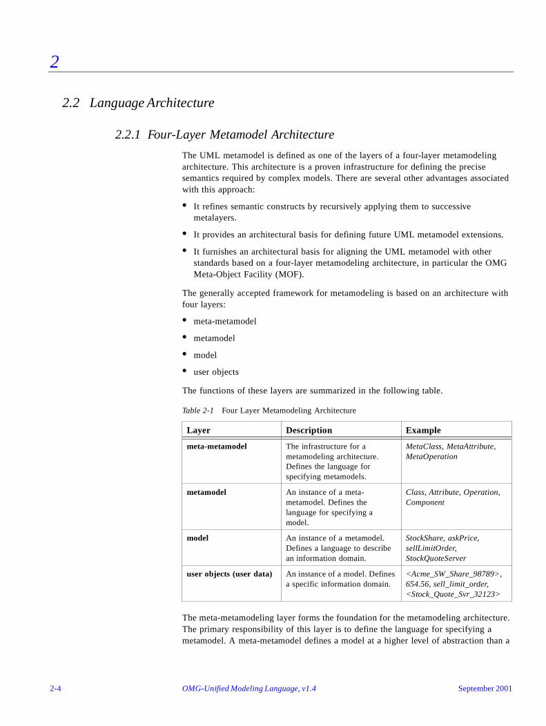
2
2.2 Language Architecture
2.2.1 Four-Layer Metamodel Architecture
The UML metamodel is defined as one of the layers of a four-layer metamodeling architecture. This architecture is a proven infrastructure for defining the precise semantics required by complex models. There are several other advantages associated with this approach:
• It refines semantic constructs by recursively applying them to successive metalayers.
• It provides an architectural basis for defining future UML metamodel extensions.
• It furnishes an architectural basis for aligning the UML metamodel with other standards based on a four-layer metamodeling architecture, in particular the OMG Meta-Object Facility (MOF).
The generally accepted framework for metamodeling is based on an architecture with four layers:
• meta-metamodel
• metamodel
• model
• user objects
The functions of these layers are summarized in the following table.
The meta-metamodeling layer forms the foundation for the metamodeling architecture. The primary responsibility of this layer is to define the language for specifying a metamodel. A meta-metamodel defines a model at a higher level of abstraction than a
Table 2-1 Four Layer Metamodeling Architecture
Layer Description Example
meta-metamodel The infrastructure for a metamodeling architecture. Defines the language for specifying metamodels.
MetaClass, MetaAttribute, MetaOperation
metamodel An instance of a meta-metamodel. Defines the language for specifying a model.
Class, Attribute, Operation, Component
model An instance of a metamodel. Defines a language to describe an information domain.
StockShare, askPrice, sellLimitOrder, StockQuoteServer
user objects (user data) An instance of a model. Defines a specific information domain.
<Acme_SW_Share_98789>, 654.56, sell_limit_order, <Stock_Quote_Svr_32123>
2-4 OMG-Unified Modeling Language, v1.4 September 2001
2
metamodel, and is typically more compact than the metamodel that it describes. A meta-metamodel can define multiple metamodels, and there can be multiple meta-metamodels associated with each metamodel.
While it is generally desirable that related metamodels and meta-metamodels share common design philosophies and constructs, this is not a strict rule. Each layer needs to maintain its own design integrity. Examples of meta-metaobjects in the meta-metamodeling layer are: MetaClass, MetaAttribute, and MetaOperation.
A metamodel is an instance of a meta-metamodel. The primary responsibility of the metamodel layer is to define a language for specifying models. Metamodels are typically more elaborate than the meta-metamodels that describe them, especially when they define dynamic semantics. Examples of metaobjects in the metamodeling layer are: Class, Attribute, Operation, and Component.
A model is an instance of a metamodel. The primary responsibility of the model layer is to define a language that describes an information domain. Examples of objects in the modeling layer are: StockShare, askPrice, sellLimitOrder, and StockQuoteServer.
User objects (a.k.a. user data) are an instance of a model. The primary responsibility of the user objects layer is to describe a specific information domain. Examples of objects in the user objects layer are: <Acme_Software_Share_98789>, 654.56, sell_limit_order, and <Stock_Quote_Svr_32123>.
2.2.1.1 Architectural Alignment with the MOF Meta-Metamodel
Both the UML and the MOF are based on a four-layer metamodel architecture, where the MOF meta-metamodel is the meta-metamodel for the UML metamodel. Since the MOF and UML have different scopes and differ in their abstraction levels (the UML metamodel tends to be more of a logical model than the MOF meta-metamodel), they are related by loose metamodeling rather than strict metamodeling.1 As a result, the UML metamodel is an instance of the MOF meta-metamodel.
Consequently, there is not a strict isomorphic instance-of mapping between all the MOF meta-metamodel elements and the UML metamodel elements. In spite of this, since the two models were designed to be interoperable, the UML Core package metamodel and the MOF meta-metamodel are structurally quite similar.
1.In loose (or “non-strict”) metamodeling a Mn level model is an instance of a Mn+1 level model. In strict metamodeling, every element of a Mn level model is an instance of exactly one element of Mn+1 level model.
September 2001 OMG-UML , v1.4 Language Architecture 2-5
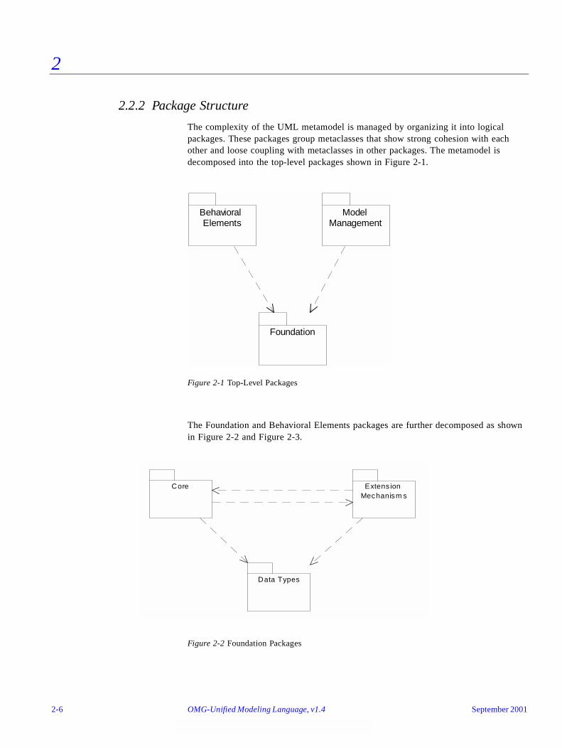
2
2.2.2 Package Structure
The complexity of the UML metamodel is managed by organizing it into logical packages. These packages group metaclasses that show strong cohesion with each other and loose coupling with metaclasses in other packages. The metamodel is decomposed into the top-level packages shown in Figure 2-1.
Figure 2-1 Top-Level Packages
The Foundation and Behavioral Elements packages are further decomposed as shown in Figure 2-2 and Figure 2-3.
Figure 2-2 Foundation Packages
Behavioral Elements
Model Management
Foundation
Core
Data Types
Extens ion Mechanism s
2-6 OMG-Unified Modeling Language, v1.4 September 2001
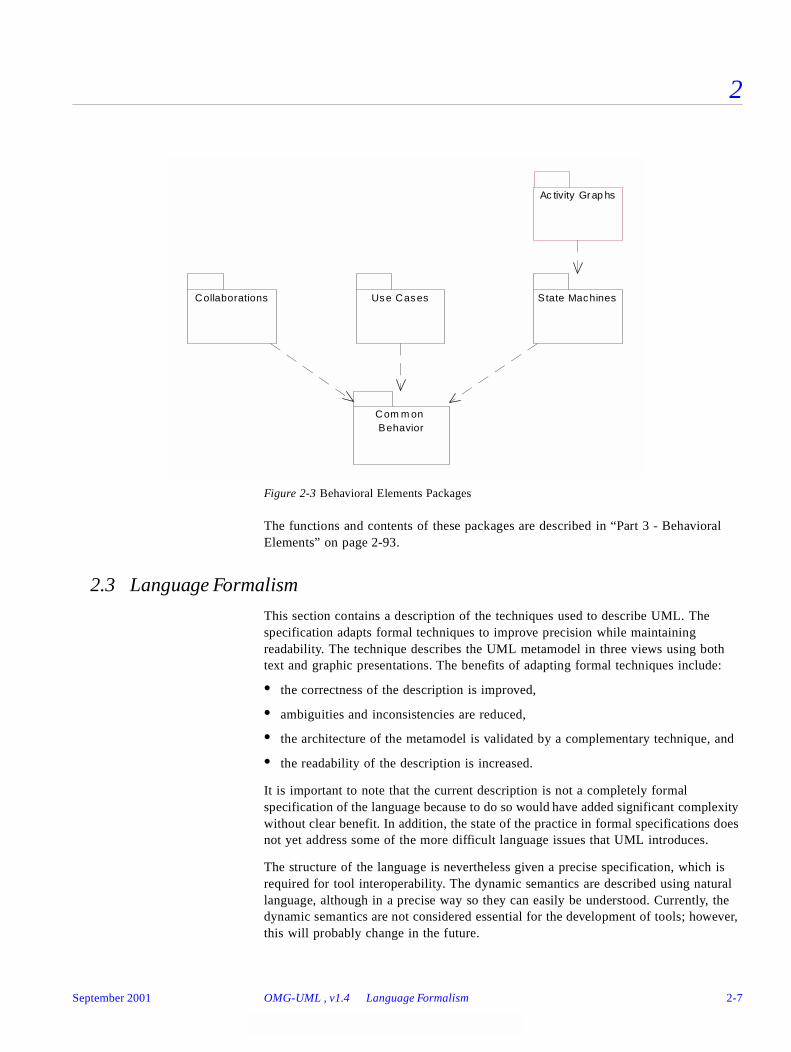
2
Figure 2-3 Behavioral Elements Packages
The functions and contents of these packages are described in “Part 3 - Behavioral Elements” on page 2-93.
2.3 Language Formalism
This section contains a description of the techniques used to describe UML. The specification adapts formal techniques to improve precision while maintaining readability. The technique describes the UML metamodel in three views using both text and graphic presentations. The benefits of adapting formal techniques include:
• the correctness of the description is improved,
• ambiguities and inconsistencies are reduced,
• the architecture of the metamodel is validated by a complementary technique, and
• the readability of the description is increased.
It is important to note that the current description is not a completely formal specification of the language because to do so would have added significant complexity without clear benefit. In addition, the state of the practice in formal specifications does not yet address some of the more difficult language issues that UML introduces.
The structure of the language is nevertheless given a precise specification, which is required for tool interoperability. The dynamic semantics are described using natural language, although in a precise way so they can easily be understood. Currently, the dynamic semantics are not considered essential for the development of tools; however, this will probably change in the future.
Use Cases State MachinesCollaborations
Com m on Behavior
Ac tivity Grap hs
September 2001 OMG-UML , v1.4 Language Formalism 2-7
2
2.3.1 Levels of Formalism
A common technique for specification of languages is to first define the syntax of the language and then to describe its static and dynamic semantics. The syntax defines what constructs exist in the language and how the constructs are built up in terms of other constructs. Sometimes, especially if the language has a graphic syntax, it is important to define the syntax in a notation independent way, that is, to define the abstract syntax of the language. The concrete syntax is then defined by mapping the notation onto the abstract syntax. The syntax is described in the Abstract Syntax sections.
The static semantics of a language define how an instance of a construct should be connected to other instances to be meaningful, and the dynamic semantics define the meaning of a well-formed construct. The meaning of a description written in the language is defined only if the description is well formed, that is, if it fulfills the rules defined in the static semantics. The static semantics are found in sections headed Well-Formedness Rules. The dynamic semantics are described under the heading Semantics. In some cases, parts of the static semantics are also explained in the Semantics section for completeness.
The specification uses a combination of languages - a subset of UML, an object constraint language, and precise natural language to describe the abstract syntax and semantics of the full UML. The description is self-contained; no other sources of information are needed to read the document2. Although this is a metacircular description3, understanding this document is practical since only a small subset of UML constructs are needed to describe its semantics.
In constructing the UML metamodel different techniques have been used to specify language constructs, using some of the capabilities of UML. The main language constructs are reified into metaclasses in the metamodel. Other constructs, in essence being variants of other ones, are defined as stereotypes of metaclasses in the metamodel. This mechanism allows the semantics of the variant construct to be significantly different from the base metaclass. Another more “lightweight” way of defining variants is to use metaattributes. As an example, the aggregation construct is specified by an attribute of the metaclass AssociationEnd, which is used to indicate if an association is an ordinary aggregate, a composite aggregate, or a common association.
2. Although a comprehension of the UML’s four-layer metamodel architecture and its underlying meta-metamodel is helpful, it is not essential to understand the UML semantics.
3. In order to understand the description of the UML semantics, you must understand some UML semantics.
2-8 OMG-Unified Modeling Language, v1.4 September 2001
2
2.3.2 Package Specification Structure
This section provides information for each package in the UML metamodel. Each package has one or more of the following subsections.
2.3.2.1 Abstract Syntax
The abstract syntax is presented in a UML class diagram showing the metaclasses defining the constructs and their relationships. The diagram also presents some of the well-formedness rules, mainly the multiplicity requirements of the relationships, and whether or not the instances of a particular sub-construct must be ordered. Finally, a short informal description in natural language describing each construct is supplied. The first paragraph of each of these descriptions is a general presentation of the construct that sets the context, while the following paragraphs give the informal definition of the metaclass specifying the construct in UML. For each metaclass, its attributes are enumerated together with a short explanation. Furthermore, the opposite role names of associations connected to the metaclass are also listed in the same way.
2.3.2.2 Well-Formedness Rules
The static semantics of UML metaclasses, except for multiplicity and ordering constraints, are defined as a set of invariants of an instance of the metaclass. (Note that a metaclass is not required to have any invariants.) These invariants have to be satisfied for the construct to be meaningful. The rules thus specify constraints over attributes and associations defined in the metamodel. Each invariant is defined by an OCL expression together with an informal explanation of the expression. In many cases, additional operations on the metaclasses are needed for the OCL expressions. These are then defined in a separate subsection after the well-formedness rules for the construct, using the same approach as the abstract syntax: an informal explanation followed by the OCL expression defining the operation.
The statement ‘No extra well-formedness rules’ means that all current static semantics are expressed in the superclasses together with the multiplicity and type information expressed in the diagrams.
2.3.2.3 Semantics
The meanings of the constructs are defined using natural language. The constructs are grouped into logical chunks that are defined together. Since only concrete metaclasses have a true meaning in the language, only these are described in this section.
2.3.2.4 Standard Elements
Stereotypes of the metaclasses defined previously in the section are listed, with an informal definition in natural language. Well-formedness rules, if any, for the stereotypes are also defined in the same manner as in the Well-Formedness Rules subsection.
September 2001 OMG-UML , v1.4 Language Formalism 2-9
2
Other kinds of standard elements (constraints and tagged-values) are listed, and are defined in the Standard Elements appendix.
2.3.2.5 Notes
This subsection may contain rationales for metamodeling decisions, pragmatics for the use of the constructs, and examples all written in natural language.
2.3.3 Use of a Constraint Language
The specification uses the Object Constraint Language (OCL), as defined in Chapter 6, “Object Constraint Language Specification” for expressing well-formedness rules. The following conventions are used to promote readability:
• Self - which can be omitted as a reference to the metaclass defining the context of the invariant, has been kept for clarity.
• In expressions where a collection is iterated, an iterator is used for clarity, even when formally unnecessary. The type of the iterator is usually omitted, but included when it adds to understanding.
• The ‘collect’ operation is left implicit where this is practical.
2.3.4 Use of Natural Language
We strove to be precise in our use of natural language, in this case English. For example, the description of UML semantics includes phrases such as “X provides the ability to…” and “X is a Y.” In each of these cases, the usual English meaning is assumed, although a deeply formal description would demand a specification of the semantics of even these simple phrases.
The following general rules apply:
• When referring to an instance of some metaclass, we often omit the word “instance.” For example, instead of saying “a Class instance” or “an Association instance,” we just say “a Class” or “an Association.” By prefixing it with an “a” or “an,” assume that we mean “an instance of.” In the same way, by saying something like “Elements” we mean “a set (or the set) of instances of the metaclass Element.”
• Every time a word coinciding with the name of some construct in UML is used, that construct is referenced.
• Terms including one of the prefixes sub, super, or meta are written as one word (for example, metamodel, subclass).
2.3.5 Naming Conventions and Typography
In the description of UML, the following conventions have been used:
• When referring to constructs in UML, not their representation in the metamodel, normal text is used.
2-10 OMG-Unified Modeling Language, v1.4 September 2001
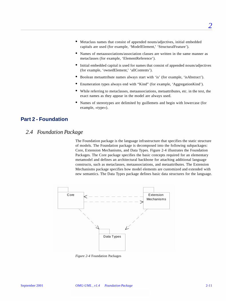
2
• Metaclass names that consist of appended nouns/adjectives, initial embedded capitals are used (for example, ‘ModelElement,’ ‘StructuralFeature’).
• Names of metaassociations/association classes are written in the same manner as metaclasses (for example, ‘ElementReference’).
• Initial embedded capital is used for names that consist of appended nouns/adjectives (for example, ‘ownedElement,’ ‘allContents’).
• Boolean metaattribute names always start with ‘is’ (for example, ‘isAbstract’).
• Enumeration types always end with “Kind” (for example, ‘AggregationKind’).
• While referring to metaclasses, metaassociations, metaattributes, etc. in the text, the exact names as they appear in the model are always used.
• Names of stereotypes are delimited by guillemets and begin with lowercase (for example, «type»).
Part 2 - Foundation
2.4 Foundation Package
The Foundation package is the language infrastructure that specifies the static structure of models. The Foundation package is decomposed into the following subpackages: Core, Extension Mechanisms, and Data Types. Figure 2-4 illustrates the Foundation Packages. The Core package specifies the basic concepts required for an elementary metamodel and defines an architectural backbone for attaching additional language constructs, such as metaclasses, metaassociations, and metaattributes. The Extension Mechanisms package specifies how model elements are customized and extended with new semantics. The Data Types package defines basic data structures for the language.
Figure 2-4 Foundation Packages
Core
Data Types
Extension Mechanisms
September 2001 OMG-UML , v1.4 Foundation Package 2-11
2
2.5 Core
2.5.1 Overview
The Core package is the most fundamental of the subpackages that compose the UML Foundation package. It defines the basic abstract and concrete metamodel constructs needed for the development of object models. Abstract constructs are not instantiable and are commonly used to reify key constructs, share structure, and organize the UML metamodel. Concrete metamodel constructs are instantiable and reflect the modeling constructs used by object modelers (cf. metamodelers). Abstract constructs defined in the Core include ModelElement, GeneralizableElement, and Classifier. Concrete constructs specified in the Core include Class, Attribute, Operation, and Association.
The Core package specifies the core constructs required for a basic metamodel and defines an architectural backbone (“skeleton”) for attaching additional language constructs such as metaclasses, metaassociations, and metaattributes. Although the Core package contains sufficient semantics to define the remainder of UML, it is not the UML meta-metamodel. It is the underlying base for the Foundation package, which in turn serves as the infrastructure for the rest of language. In other packages, the Core is extended by adding metaclasses to the backbone using generalizations and associations.
The following sections describe the abstract syntax, well-formedness rules, and semantics of the Core package.
2.5.2 Abstract Syntax
The abstract syntax for the Core package is expressed in graphic notation in the following figures. Figure 2-5 on page 2-13 shows the model elements that form the structural backbone of the metamodel. Figure 2-6 on page 2-14 shows the model elements that define relationships. Figure 2-7 on page 2-15 shows the model elements that define dependencies. Figure 2-8 on page 2-16 shows the various kinds of classifiers. Figure 2-9 on page 2-17 shows auxiliary elements for template parameters, presentation elements, and comments.
2-12 OMG-Unified Modeling Language, v1.4 September 2001
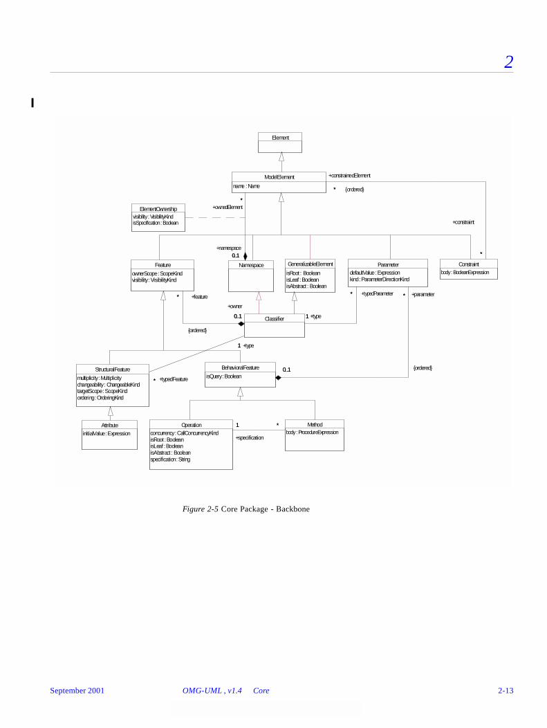
2
Figure 2-5 Core Package - Backbone
Element
GeneralizableElement
isRoot : BooleanisLeaf : BooleanisAbstract : Boolean
AttributeinitialValue : Expression
Methodbody : ProcedureExpression
Operationconcurrency : CallConcurrencyKindisRoot : BooleanisLeaf : BooleanisAbstract : Booleanspecification : String
*1 *
+specification
1
ElementOwnershipvisibility : VisibilityKindisSpecification : Boolean
Namespace Constraintbody : BooleanExpression
ModelElement
name : Name
0..1
*
+namespace0..1
+ownedElement*
*
*
+constraint
*
+constrainedElement
* {ordered}
BehavioralFeature
isQuery : Boolean
Feature
ownerScope : ScopeKindvisibility : VisibilityKind
StructuralFeature
multiplicity : Multiplicitychangeability : ChangeableKindtargetScope : ScopeKindordering : OrderingKind
ParameterdefaultValue : Expressionkind : ParameterDirectionKind
0..1
*
0..1
+parameter*
{ordered}
Classifier
*
0..1
+feature*
{ordered}
+owner
0..1
*
1
+typedFeature*
+type1
*
1
+typedParameter*
+type1
September 2001 OMG-UML , v1.4 Core 2-13
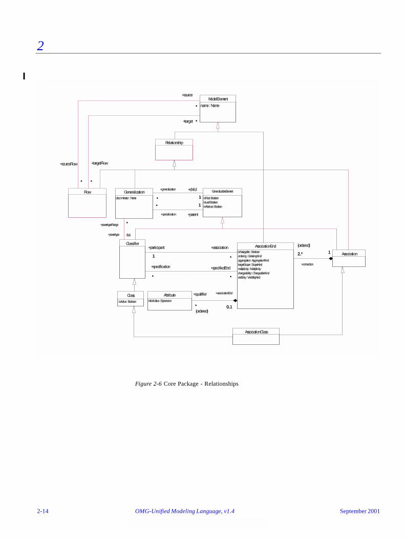
2
Figure 2-6 Core Package - Relationships
{ordered}
AssociationClass
ClassisActive : Boolean
Relationship
Flow
ModelElement
name : Name
*
*
+sourceFlow
*
+source
*
*
*
+targetFlow
*
+target *
Association
AttributeinitialValue : Expression
AssociationEndisNavigable : Booleanordering : OrderingKindaggregation : AggregationKindtargetScope : ScopeKindmultiplicity : Multiplicitychangeability : ChangeableKindvisibility : VisibilityKind
2..* 1
+connection
2..* 1
* 0..1
+qualifier
*{ordered}
+associationEnd
0..1
GeneralizableElement
isRoot : BooleanisLeaf : BooleanisAbstract : Boolean
Classifier
1 *
+participant
1
+association
*
**
+specifiedEnd
*
+specification
*
Generalizationdiscriminator : Name * 1
+generalization
*
+child
1
1*
+parent
1
+specialization
*
0..1
*
+powertype 0..1
+powertypeRange *
2-14 OMG-Unified Modeling Language, v1.4 September 2001
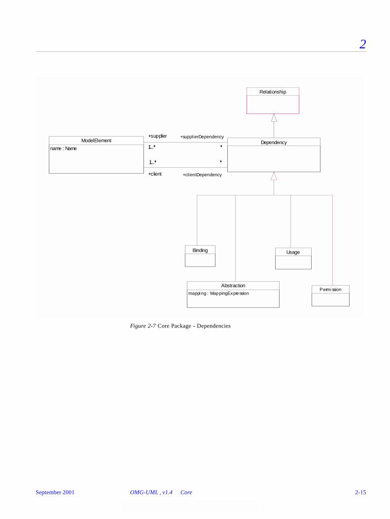
2
Figure 2-7 Core Package - Dependencies
Usage
Permi ssionAbstraction
mappi ng : MappingExpression
Dependency
Binding
ModelElement
name : Name 1..* *
+supplier
1..*
+supplierDependency
*
1..* *
+client
1..*
+clientDependency
*
Relationship
September 2001 OMG-UML , v1.4 Core 2-15
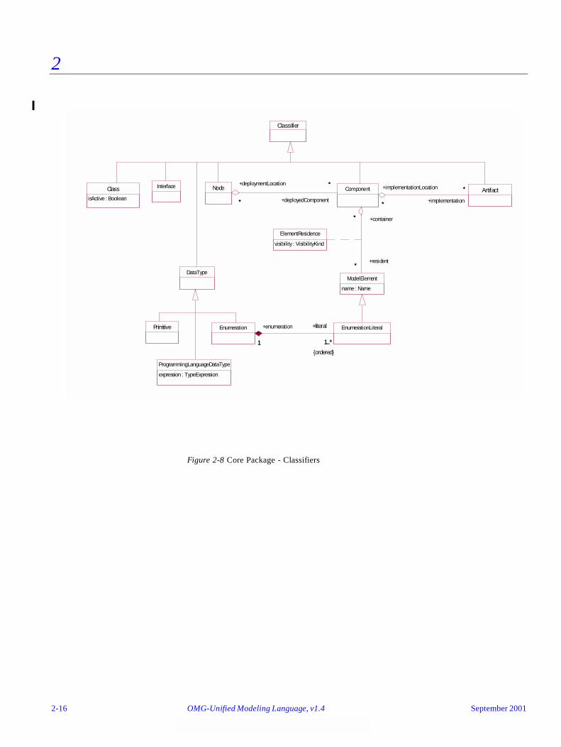
2
Figure 2-8 Core Package - Classifiers
EnumerationLiteral
Classifier
Class
isActive : Boolean
DataType
Interface
ElementResidence
visibility : VisibilityKind
Primitive Enumeration
1 1..*
+enumeration
1
+literal
1..*
{ordered}
Node
ModelElement
name : Name
ArtifactComponent
*
*+deploymentLocation
* +deployedComponent
*
*
*
+container*
+resident*
*
* +implementation
*+implementationLocation
*
ProgrammingLanguageDataType
expression : TypeExpression
2-16 OMG-Unified Modeling Language, v1.4 September 2001
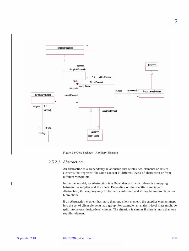
2
Figure 2-9 Core Package - Auxiliary Elements
2.5.2.1 Abstraction
An abstraction is a Dependency relationship that relates two elements or sets of elements that represent the same concept at different levels of abstraction or from different viewpoints.
In the metamodel, an Abstraction is a Dependency in which there is a mapping between the supplier and the client. Depending on the specific stereotype of Abstraction, the mapping may be formal or informal, and it may be unidirectional or bidirectional.
If an Abstraction element has more than one client element, the supplier element maps into the set of client elements as a group. For example, an analysis-level class might be split into several design-level classes. The situation is similar if there is more than one supplier element.
Element
PresentationElement
TemplateParameter
Comment
body : String
ModelElement
name : Name
**
+presentation
*
+subject
*
0..1*
+template
0..1
+templateParameter
*
{ordered}
0..1
*
+defaultElement0..1
*
*
*
*
+annotatedElement*
Binding
TemplateArgument
* 1*
+modelElement
1
1
1..*
+binding1
+argument 1..*
{ordered}
September 2001 OMG-UML , v1.4 Core 2-17
2
The UML standard stereotyped classes of Abstraction are Derivation, Realization, Refinement, and Trace. (These are the names for the Abstraction class with the stereotypes «derive», «realize», «refine», and «trace», respectively.)
Attributes
Stereotypes
mapping A MappingExpression that states the abstraction relationship between the supplier and the client. In some cases, such as Derivation, it is usually formal and unidirectional; in other cases, such as Trace, it is usually informal and bidirectional. The mapping attribute is optional and may be omitted if the precise relationship between the elements is not specified.
«derive» (Name for the stereotyped class is Derivation.) Specifies a derivation relationship among model elements that are usually, but not necessarily, of the same type. A derived dependency specifies that the client may be computed from the supplier. The mapping specifies the computation. The client may be implemented for design reasons, such as efficiency, even though it is logically redundant.
«realize» (Name for the stereotyped class is Realization.) Specifies a realization relationship between a specification model element or elements (the supplier) and a model element or elements that implement it (the client). The implementation model element is required to support all of the operations or received signals that the specification model element declares. The implementation model element must make or inherit its own declarations of the operations and signal receptions. The mapping specifies the relationship between the two. The mapping may or may not be computable. Realization can be used to model stepwise refinement, optimizations, transformations, templates, model synthesis, framework composition, etc.
«refine» (Name for the stereotyped class is Refinement.) Specifies refinement relationship between model elements at different semantic levels, such as analysis and design. The mapping specifies the relationship between the two elements or sets of elements. The mapping may or may not be computable, and it may be unidirectional or bidirectional. Refinement can be used to model transformations from analysis to design and other such changes.
«trace» (Name for the stereotyped class is Trace.) Specifies a trace relationship between model elements or sets of model elements that represent the same concept in different models. Traces are mainly used for tracking requirements and changes across models. Since model changes can occur in both directions, the directionality of the dependency can often be ignored. The mapping specifies the relationship between the two, but it is rarely computable and is usually informal.
2-18 OMG-Unified Modeling Language, v1.4 September 2001
2
2.5.2.2 Artifact
An Artifact represents a physical piece of information that is used or produced by a software development process. Examples of Artifacts include models, source files, scripts, and binary executable files. An Artifact may constitute the implementation of a deployable component.
In the metamodel, an Artifact is a Classifier with an optional aggregation association to one or more Components. As a Classifier, Artifacts may have Features that represent properties of the Artifact (for example, a “read-only” attribute or a “check in” operation).
It should be noted that sometimes Artifacts may need to be linked to Classifiers directly, without introducing a ‘Component.’ For instance, in the context of code generation, the resulting Artifacts (source code files) are never deployed as Components. In that case, a «derive» Dependency can be used between the Classifier(s) and the generated Artifact.
The standard stereotypes of Artifact are «file», the subclasses of «file» («executable», «source», «library», and «document»), and «table». These stereotypes can be further subclassed into implementation and platform specific stereotypes (for example, «jarFile» for Java archives).
Associations
Stereotypes
2.5.2.3 Association
An association defines a semantic relationship between classifiers. The instances of an association are a set of tuples relating instances of the classifiers. Each tuple value may appear at most once.
implementationLocation The deployable Component(s) that are implemented by this Artifact.
«document» Denotes a generic file that is not a «source» file or «executable». Subclass of «file».
«executable» Denotes a program file that can be executed on a computer system. Subclass of «file».
«file» Denotes a physical file in the context of the system developed.
«library» Denotes a static or dynamic library file. Subclass of «file».
«source» Denotes a source file that can be compiled into an executable file. Subclass of «file».
«table» Denotes a database table.
September 2001 OMG-UML , v1.4 Core 2-19
2
In the metamodel, an Association is a declaration of a semantic relationship between Classifiers, such as Classes. An Association has at least two AssociationEnds. Each end is connected to a Classifier - the same Classifier may be connected to more than one AssociationEnd in the same Association. The Association represents a set of connections among instances of the Classifiers. An instance of an Association is a Link, which is a tuple of Instances drawn from the corresponding Classifiers.
Attributes
Associations
Stereotypes
Standard Constraints
Tagged Values
Inherited Features
Association is a GeneralizableElement. The following elements are inherited by a child Association.
name The name of the Association that in combination with its associated Classifiers must be unique within the enclosing namespace (usually a Package).
connection An Association consists of at least two AssociationEnds, each of which represents a connection of the association to a Classifier. Each AssociationEnd specifies a set of properties that must be fulfilled for the relationship to be valid. The bulk of the structure of an Association is defined by its AssociationEnds. The classifiers belonging to the association are related to the AssociationEnds by the participant rolename association.
implicit The «implicit» stereotype is applied to an association, specifying that the association is not manifest, but rather is only conceptual.
xor The {xor} constraint is applied to a set of associations, specifying that over that set, exactly one is manifest for each associated instance. Xor is an exclusive or (not inclusive or) constraint.
persistence Persistence denotes the permanence of the state of the association, marking it as transitory (its state is destroyed when the instance is destroyed) or persistent (its state is not destroyed when the instance is destroyed).
2-20 OMG-Unified Modeling Language, v1.4 September 2001
2
Non-Inherited Features
2.5.2.4 AssociationClass
An association class is an association that is also a class. It not only connects a set of classifiers but also defines a set of features that belong to the relationship itself and not any of the classifiers.
Inherited Features
AssociationClass inherits features as specified in both Class and Association.
In the metamodel, an AssociationClass is a declaration of a semantic relationship between Classifiers, which has a set of features of its own. AssociationClass is a subclass of both Association and Class (that is, each AssociationClass is both an Association and a Class); therefore, an AssociationClass has both AssociationEnds and Features.
2.5.2.5 AssociationEnd
An association end is an endpoint of an association, which connects the association to a classifier. Each association end is part of one association. The association-ends of each association are ordered.
In the metamodel, an AssociationEnd is part of an Association and specifies the connection of an Association to a Classifier. It has a name and defines a set of properties of the connection (for example, which Classifier the Instances must conform to, their multiplicity, and if they may be reached from another Instance via this connection).
In the following descriptions when referring to an association end for a binary association, the source end is the other end. The target end is the one whose properties are being discussed.
connection The child must have the same number of ends as the parent. Each participant class must be a descendant of the participant class in the same position in the parent. If the Association is an AssociationClass, its class properties (attributes, operations, etc.) are inherited. Various other properties are subject to change in the child. This specification is likely to be further clarified in UML 2.0.
isRootisLeafisAbstract
Not inheritable by their very nature, but they define the generalization structure.
name Each model element has a unique name.
September 2001 OMG-UML , v1.4 Core 2-21
2
Attributes
aggregation When placed on one end (the “target” end), specifies whether the class on the target end is an aggregation with respect to the class on the other end (the “source”end). Only one end can be an aggregation.
Possibilities are:• none - The target class is not an aggregate.• aggregate - The target class is an aggregate; therefore, the
source class is a part and must have the aggregation value of none. The part may be contained in other aggregates.
• composite - The target class is a composite; therefore, the source class is a part and must have the aggregation value of none. The part is strongly owned by the composite and may not be part of any other composite.
changeability When placed on one end (the “target” end), specifies whether an instance of the Association may be modified by an instance of the class on the other end (the “source” end). In other words, the attribute controls the access by operations on the class on the opposite end.
Possibilities are:• changeable - No restrictions on modification.• frozen - No links may be added by operations on the source
class after the creation of the source object. Operations on the target class may add links (provided they are not similarly restricted).
• addOnly - Links may be added at any time by operations on the source object, but once created a link may not be removed by operations on the source class. Operations on the target class may add or remove links (provided they are not similarly restricted).
ordering When placed on a target end, specifies whether the set of links from the source instance to the target instance is ordered. The ordering must be determined and maintained by Operations that add links. It represents additional information not inherent in the objects or links themselves.
Possibilities are:• unordered - The links form a set with no inherent ordering. • ordered - A set of ordered links can be scanned in order. • Other possibilities (such as sorted) may be defined later by
declaring additional keywords. As with user-defined stereotypes, this would be a private extension supported by particular editing tools.
2-22 OMG-Unified Modeling Language, v1.4 September 2001
2
isNavigable When placed on a target end, specifies whether traversal from a source instance to its associated target instances is possible. Specification of each direction across the Association is independent. A value of true means that the association can be navigated by the source class and the target rolename can be used in navigation expressions.
multiplicity When placed on a target end, specifies the number of target instances that may be associated with a single source instance across the given Association.
name (Inherited from ModelElement) The rolename of the end. When placed on a target end, provides a name for traversing from a source instance across the association to the target instance or set of target instances. It represents a pseudo-attribute of the source classifier; that is, it may be used in the same way as an Attribute and must be unique with respect to Attributes and other pseudo-attributes of the source Classifier.
targetScope Specifies whether the target value is an instance or a classifier.
Possibilities are:• instance. An instance value is part of each link. This is the
default.• classifier. A classifier itself is part of each link. Normally this
would be fixed at modeling time and need not be stored separately at run time.
visibility Specifies the visibility of the association end from the viewpoint of the classifier on the other end.
Possibilities are:• public - Other classifiers may navigate the association and use
the rolename in expressions, similar to the use of a public attribute.
• protected - Descendants of the source classifier may navigate the association and use the rolename in expressions, similar to the use of a protected attribute.
• private - Only the source classifier may navigate the association and use the rolename in expressions, similar to the use of a private attribute.
• package - Classifiers in the same package (or a nested subpackage, to any level) as the association declaration may navigate the association and use the rolename in expressions.
September 2001 OMG-UML , v1.4 Core 2-23
2
Associations
Stereotypes
2.5.2.6 Attribute
An attribute is a named slot within a classifier that describes a range of values that instances of the classifier may hold.
In the metamodel, an Attribute is a named piece of the declared state of a Classifier, particularly the range of values that Instances of the Classifier may hold.
Attributes
qualifier An optional list of qualifier Attributes for the end. If the list is empty, then the Association is not qualified.
specification Designates zero or more Classifiers that specify the Operations that may be applied to an Instance accessed by the AssociationEnd across the Association. These determine the minimum interface that must be realized by the actual Classifier attached to the end to support the intent of the Association. May be an Interface or another Classifier. These classifiers do not indicate the classes of the participants in a link, merely the operations that may be applied when traversing a link.
participant Designates the Classifier participating in the Association at the given end. A link of the Association contains a reference to an instance of the class (including a descendant of the given class or a class that realizes a given interface) in the given position in the link.
(unnamed composite end)
Designates the Association that owns the AssociationEnd.
«association» Specifies a real association (default and redundant, but may be included for emphasis).
«global» Specifies that the target is a global value that is known to all elements rather than an actual association.
«local» Specifies that the relationship represents a local variable within a procedure rather than an actual association.
«parameter» Specifies that the relationship represents a procedure parameter rather than an actual association.
«self» Specifies that the relationship represents a reference to the object that owns an operation or action rather than an actual association.
initialValue An Expression specifying the value of the attribute upon initialization. It is meant to be evaluated at the time the object is initialized. (Note that an explicit constructor may supersede an initial value.)
2-24 OMG-Unified Modeling Language, v1.4 September 2001

2
Associations
2.5.2.7 BehavioralFeature
A behavioral feature refers to a dynamic feature of a model element, such as an operation or method.
In the metamodel, a BehavioralFeature specifies a behavioral aspect of a Classifier. All different kinds of behavioral aspects of a Classifier, such as Operation and Method, are subclasses of BehavioralFeature. BehavioralFeature is an abstract metaclass.
Attributes
Associations
Stereotypes
2.5.2.8 Binding
A binding is a relationship between a template (as supplier) and a model element generated from the template (as client). It includes a list of arguments that match the template parameters. The template is a form that is cloned and modified by substitution
associationEnd Designates the optional AssociationEnd that owns a qualifier attribute. Note that an attribute may be part of an AssociationEnd (in which case it is a qualifier) or part of a Classifier (by inheritance from Feature, in which case it is a feature) but not both. If the value is empty, the attribute is not a qualifier attribute.
isQuery Specifies whether an execution of the Feature leaves the state of the system unchanged. True indicates that the state is unchanged; false indicates that side-effects may occur.
name (Inherited from ModelElement) The name of the Feature. The entire signature of the Feature (name and parameter list) must be unique within its containing Classifier.
parameter An ordered list of Parameters for the Operation. To call the Operation, the caller must supply a list of values compatible with the types of the Parameters.
«create» Specifies that the designated feature creates an instance of the classifier to which the feature is attached. May be promoted to the Classifier containing the feature.
«destroy» Specifies that the designated feature destroys an instance of the classifier to which the feature is attached. May be promoted to the classifier containing the feature.
September 2001 OMG-UML , v1.4 Core 2-25
2
to yield an implicit model fragment that behaves as if it were a direct part of the model. A Binding must have one supplier and one client; unlike a general Dependency, the supplier and client may not be sets.
In the metamodel, a Binding is a Dependency where the supplier is the template and the client is the instantiation of the template that performs the substitution of parameters of a template. A Binding has a list of arguments that replace the parameters of the supplier to yield the client. The client is fully specified by the binding of the supplier’s parameters and does not add any information of its own. An element may participate as a supplier in multiple Binding relationships to different clients. An element may participate in only one Binding relationship as a client.
Associations
2.5.2.9 Class
A class is a description of a set of objects that share the same attributes, operations, methods, relationships, and semantics. A class may use a set of interfaces to specify collections of operations it provides to its environment.
In the metamodel, a Class describes a set of Objects sharing a collection of Features, including Operations, Attributes and Methods, that are common to the set of Objects. Furthermore, a Class may realize zero or more Interfaces; this means that its full descriptor (see Section 2.5.4.4, “Inheritance,” on page 2-70 for the definition) must contain every Operation from every realized Interface (it may contain additional operations as well).
A Class defines the data structure of Objects, although some Classes may be abstract; that is, no Objects can be created directly from them. Each Object instantiated from a Class contains its own set of values corresponding to the StructuralFeatures declared in the full descriptor. Objects do not contain values corresponding to BehavioralFeatures or class-scope Attributes; all Objects of a Class share the definitions of the BehavioralFeatures from the Class, and they all have access to the single value stored for each class-scope attribute.
Attributes
argument An ordered list of arguments. Each argument is a TemplateArgument element. The model element attached to the TemplateArgument by the modelElement association replaces the corresponding supplier parameter in the supplier definition, and the result represents the definition of the client as if it had been defined directly.
isActive Specifies whether an Object of the Class maintains its own thread of control. If true, then an Object has its own thread of control and runs concurrently with other active Objects. Such a class is informally called an active class. If false, then Operations run in the address space and under the control of the active Object that controls the caller. Such a class is informally called a passive class.
2-26 OMG-Unified Modeling Language, v1.4 September 2001
2
Stereotypes
Inherited Features
Class is a GeneralizableElement. The following elements are inherited by a child classifier, in addition to those specified under its parent, Classifier.
«auxiliary» Specifies a class that supports another more central or fundamental class, typically by implementing secondary logic or control flow. The class that the auxiliary supports may be defined explicitly using a Focus class or implicitly by a dependency relationship. Auxiliary classes are typically used together with Focus classes, and are particularly useful for specifying the secondary business logic or control flow of components during design. See also: «focus».
«focus» Specifies a class that defines the core logic or control flow for one or more auxiliary classes that support it. Support classes may be defined explicitly using Auxiliary classes or implicitly by dependency relationships. Focus classes are typically used together with one or more Auxiliary classes, and are particularly useful for specifying the core business logic or control flow of components during design. See also: «auxiliary».
«implementation» Specifies the implementation of a class in some programming language (for example, C++, Smalltalk, Java) in which an instance may not have more than one class. This is in contrast to Class, for which an instance may have multiple classes at one time and may gain or lose classes over time, and an object (a child of instance) may dynamically have multiple classes.
An Implementation class is said to realize a Type if it provides all of the operations defined for the Type with the same behavior as specified for the Type’s operations. An Implementation Class may realize a number of different Types. Note that the physical attributes and associations of the Implementation class do not have to be the same as those of any Type it realizes and that the Implementation Class may provide methods for its operations in terms of its physical attributes and associations. See also: «type».
«type» Specifies a domain of objects together with the operations applicable to the objects, without defining the physical implementation of those objects. A type may not contain any methods, maintain its own thread of control, or be nested. However, it may have attributes and associations. The associations of a Type are defined solely for the purpose of specifying the behavior of the type's operations and do not represent the implementation of state data.
Although an object may have at most one Implementation Class, it may conform to multiple different Types. See also: «implementation».
isActive The child may be active when the parent is passive, but not vice versa. In most cases, they are the same.
September 2001 OMG-UML , v1.4 Core 2-27
2
2.5.2.10 Classifier
A classifier is an element that describes behavioral and structural features; it comes in several specific forms, including class, data type, interface, component, artifact, and others that are defined in other metamodel packages.
In the metamodel, a Classifier declares a collection of Features, such as Attributes, Methods, and Operations. It has a name, which is unique in the Namespace enclosing the Classifier. Classifier is an abstract metaclass.
Classifier is a child of GeneralizableElement and Namespace. As a GeneralizableElement, it may inherit Features and participation in Associations (in addition to things inherited as a ModelElement). It also inherits ownership of StateMachines, Collaborations, etc.
As a Namespace, a Classifier may declare other Classifiers nested in its scope. Nested Classifiers may be accessed by other Classifiers only if the nested Classifiers have adequate visibility. There are no data value or state consequences of nested Classifiers (i.e., it is not an aggregation or composition).
Associations
feature An ordered list of Features, like Attribute, Operation, Method, owned by the Classifier.
association Denotes the AssociationEnd of an Association in which the Classifier participates at the given end. This is the inverse of the participant association from AssociationEnd. A link of the association contains a reference to an instance of the class in the given position.
powertypeRange Designates zero or more Generalizations for which the Classifier is a powertype. If the cardinality is zero, then the Classifier is not a powertype; if the cardinality is greater than zero, then the Classifier is a powertype over the set of Generalizations designated by the association, and the child elements of the Generalizations are the instances of the Classifier as a powertype. A Classifier that is a powertype can be marked with the «powertype» stereotype.
specifiedEnd Indicates an AssociationEnd for which the given Classifier specifies operations that may be applied to instances obtained by traversing the association from the other end. (This relationship does not define the structure of the association, merely operations that may be applied on traversing it.)
2-28 OMG-Unified Modeling Language, v1.4 September 2001
2
Stereotypes
Tagged Values
Inherited Features
Classifier is a GeneralizableElement. The following elements are inherited by a child classifier. Note that inheritance makes the inherited elements part of the (virtual) full descriptor of the classifier, but it does not change its actual data structure. See the explanation for the meaning of each kind of inheritance.
«metaclass» Specifies that the instances of the classifier are classes.
«powertype» Specifies that the classifier is a metaclass whose instances are siblings marked by the same discriminator. For example, the metaclass TreeSpecies might be a power type for the subclasses of Tree that represent different species, such as AppleTree, BananaTree, and CherryTree.
«process» Specifies a classifier that represents a heavy-weight flow of control.
«thread» Specifies a classifier that represents a flow of control.
«utility» Specifies a classifier that has no instances, but rather denotes a named collection of non-member attributes and operations, all of which are class-scoped.
persistence Persistence denotes the permanence of the state of the classifier, marking it as transitory (its state is destroyed when the instance is destroyed) or persistent (its state is not destroyed when the instance is destroyed).
semantics Semantics is the specification of the meaning of the classifier.
associationEnd The child class inherits participation in all associations of its parent, subject to all the same properties.
constraint Constraints on the parent apply to the child.
September 2001 OMG-UML , v1.4 Core 2-29
2
Non-Inherited Features
The following elements are not inherited by a child classifier:
2.5.2.11 Comment
A comment is an annotation attached to a model element or a set of model elements. It has no semantic force but may contain information useful to the modeler.
Attributes
feature Attributes of the parent are part of the full descriptor of the child and may not be declared again or overridden.Operations of the parent are part of the full descriptor of the child but may be overridden; a redeclaration may change its hierarchy location (isRoot, isLeaf, isAbstract) but may not change its specification or parameter structure. The concurrency level may be loosened (e.g., from guarded to concurrent). An overriding operation may link to a different Method. An overriding operation can have isQuery=true when the parent had a false value, but not vice versa (in other words, once a side-effect, always a side-effect).
Methods of the parent are part of the full descriptor of the child but may be overridden. An overriding method can set the isQuery status, change its hierarchy structure, but may not change its parameter structure. It may link to a different operation that overrides the operation of the parent method.
generalizationspecialization
These are implicitly inherited, in the sense that they define ancestors and descendants, but not explicitly inherited, as they are the arcs in the generalization graph. They establish the generalization structure itself as a directed graph, into which the child classifier fits.
ownedElement The namespace of the parent is available to the child, except for private access.
isRootisLeafisAbstract
By their very nature, these are not inherited.
name Each classifier has its own unique name.
parameter Template structure is not inherited. Each classifier must declare its own template structure, if any. A nontemplate can be child of a template and vice versa.
powertypeRange A powertype corresponds to a particular node in the generalization hierarchy, so it is not inherited.
body A string that is the comment.
2-30 OMG-Unified Modeling Language, v1.4 September 2001
2
Associations
Stereotypes
2.5.2.12 Component
A component represents a modular, deployable, and replaceable part of a system that encapsulates implementation and exposes a set of interfaces.
A component is typically specified by one or more classifiers that reside on the component. A subset of these classifiers explicitly defines the component’s external interfaces. A component conforms to the interfaces that it exposes, where the interfaces represent services provided by elements that reside on the component. A component may be implemented by one or more artifacts, such as binary, executable, or script files. A component may be deployed on a node.
Components may be specified in both design models (for example, using static structure diagrams) and in implementation models (for example, using implementation diagrams). When they are specified as part of a design model components need not be allocated to nodes, nor do they need to have any associated implementation artifacts.
In the metamodel, a Component is a child of Classifier. It does not have its own Features, but instead acts as a container for other Classifiers that have Features. A Component is specified by the Interfaces it exposes and the Classifiers that reside on it. The visibility attribute of the ElementResidence association defines whether a resident element is visible outside the Component: an external Interface of a Component has visibility value ‘public.’ A Component may be implemented by one or more Artifacts, and may be deployed on a Node.
Associations
annotatedElement A ModelElement or set of ModelElements described by the Comment.
«requirement» Specifies a desired feature, property, or behavior of an element as part of a system.
«responsibility» Specifies a contract or an obligation of an element in its relationship to other elements.
deploymentLocation The set of Nodes the Component is residing on.
resident Association class ElementResidence - The set of model elements that specify the component. The visibility attribute shows the external visibility of the element outside the component: an external Interface of a Component has visibility = ‘public’ for its ElementResidence association.
implementation The set of Artifacts that implement the Component. For a Component, these Artifacts are generally «executable».
September 2001 OMG-UML , v1.4 Core 2-31
2
Inherited Features
The following elements are inherited by a child Component, in addition to those specified under Classifier.
Non-Inherited Features
2.5.2.13 Constraint
A constraint is a semantic condition or restriction expressed in text.
In the metamodel, a Constraint is a BooleanExpression on an associated ModelElement(s), which must be true for the model to be well formed. This restriction can be stated in natural language, or in different kinds of languages with a well-defined semantics. Certain Constraints are predefined in the UML, others may be user defined. Note that a Constraint is an assertion, not an executable mechanism. It indicates a restriction that must be enforced by correct design of a system.
Attributes
Associations
(none)
deploymentLocation The set of locations may differ. Often it is more restrictive on the child.
resident The set of resident elements may differ. Often it is more restrictive on the child and contains additional elements.
implementation The set of Artifacts that implement the child Component will usually differ.
body A BooleanExpression that must be true when evaluated for an instance of a system to be well-formed.
constrainedElement A ModelElement or list of ModelElements affected by the Constraint. If the constrained element is a Stereotype, then the constraint applies to all ModelElements that use the stereotype.
2-32 OMG-Unified Modeling Language, v1.4 September 2001
2
Stereotypes
2.5.2.14 DataType
A data type is a type whose values have no identity; that is, they are pure values. Data types include primitive built-in types (such as integer and string) as well as definable enumeration types (such as the predefined enumeration type boolean whose literals are false and true).
In the metamodel, a DataType defines a special kind of Classifier in which Operations are all pure functions; that is, they can return DataValues but they cannot change DataValues, because they have no identity. For example, an “add” operation on a number with another number as an argument yields a third number as a result; the target and argument are unchanged.
Inherited Features
DataType inherits features as specified in Classifier.
2.5.2.15 Dependency
A term of convenience for a Relationship other than Association, Generalization, Flow, or metarelationship (such as the relationship between a Classifier and one of its Instances).
A dependency states that the implementation or functioning of one or more elements requires the presence of one or more other elements.
In the metamodel, a Dependency is a directed relationship from a client (or clients) to a supplier (or suppliers) stating that the client is dependent on the supplier; that is, the client element requires the presence and knowledge of the supplier element.
The kinds of Dependency are Abstraction, Binding, Permission, and Usage. Various stereotypes of those elements are predefined.
«invariant» Specifies a constraint that must be attached to a set of classifiers or relationships. It indicates that the conditions of the constraint must hold over time (for the time period of concern in the particular containing element) for the classifiers or relationships and their instances.
«postcondition» Specifies a constraint that must be attached to an operation, and denotes that the conditions of the constraint must hold after the invocation of the operation.
«precondition» Specifies a constraint that must be attached to an operation, and denotes that the conditions of the constraint must hold for the invocation of the operation.
«stateInvariant» Specifies a constraint that must be attached to a state vertex in a state machine that has a classifier for a context. The stereotype indicates that the constraint holds for instances of the classifier when an instance is in that state.
September 2001 OMG-UML , v1.4 Core 2-33
2
Associations
2.5.2.16 Element
An element is an atomic constituent of a model.
In the metamodel, an Element is the top metaclass in the metaclass hierarchy. It has two subclasses: ModelElement and PresentationElement. Element is an abstract metaclass.
Tagged Values
2.5.2.17 ElementOwnership
Element ownership defines the visibility of a ModelElement contained in a Namespace.
In the metamodel, ElementOwnership reifies the relationship between ModelElement and Namespace denoting the ownership of a ModelElement by a Namespace and its visibility outside the Namespace. See Section 2.5.2.27, “ModelElement,” on page 2-42.
client The element that is affected by the supplier element. In some cases (such as a Trace Abstraction) the direction is unimportant and serves only to distinguish the two elements.
supplier Inverse of client. Designates the element that is unaffected by a change. In a two-way relationship (such as some Refinement Abstractions) this would be the more general element. In an undirected situation, such as a Trace Abstraction, the choice of client and supplier may be irrelevant.
documentation Documentation is a comment, description, or explanation of the element to which it is attached.
2-34 OMG-Unified Modeling Language, v1.4 September 2001
2
Attributes
2.5.2.18 ElementResidence
Association class between Component and ModelElement that defines the set of ModelElements that specify a Component. See Component::resident in Section 2.5.2.12, “Component,” on page 2-31. Shows that the component supports the element. The visibility attribute of ElementResidence defines the visibility of a resident element outside the component: an external Interface of a Component has visibility = ‘public’ for its ElementResidence association.
Attributes
isSpecification Specifies whether the ownedElement is part of the specification for the containing namespace (in cases where specification is distinguished from the realization). Otherwise the ownedElement is part of the realization. In cases in which the distinction is not made, the value is false by default.
visibility Specifies whether the ModelElement can be seen and referenced by other ModelElements.
Possibilities include:• public - Any outside ModelElement can see the ModelElement.• protected - Any descendant of the ModelElement can see the
ModelElement.• private - Only the ModelElement itself, or elements nested within
it can see the ModelElement.• package - ModelElements declared in the same package (or a
nested subpackage, to any level) as the given ModelElement can see the ModelElement.
Note that use of an element in another Package may also be subject to access or import of its Package as described in Model Management; see Permission.
visibility Specifies whether a ModelElement that resides in a Component is visible externally. Possible values for ElementResidence visibility are:
• public - Any resident ModelElement with public visibility is part of the Component’s external Interface and can be used by other elements, if they have permission to access or import the Component.
• private - The ModelElement is internal to the Component and cannot be used by external elements.
• protected - The ModelElement is only visible to Descendant Components.
Note: the visibility values ‘package’ does not apply to Element Residence visibility. The Component and its residents have ElementOwnership associations with visibility values to the Package that contains them.
September 2001 OMG-UML , v1.4 Core 2-35
2
2.5.2.19 Enumeration
In the metamodel, Enumeration defines a kind of DataType whose range is a list of predefined values, called enumeration literals.
Enumeration literals can be copied, stored as values, and passed as arguments. They are ordered within their enumeration datatype. An enumeration literal can be compared for an exact match or to a range within its enumeration datatype. There is no other algebra defined on them (e.g., they cannot be added or subtracted).
The run-time instances of a Primitive datatype are Values. Each such value corresponds to exactly one EnumerationLiteral defined as part of the Enumeration type itself.
An Enumeration may have operations, but they must be pure functions (this is the rule for all DataType elements).
Associations
2.5.2.20 EnumerationLiteral
An EnumerationLiteral defines an element of the run-time extension of an Enumeration data type. It has no relevant substructure, that is, it is atomic. The enumeration literals of a particular Enumeration datatype are ordered.
It has a name (inherited from ModelElement) that can be used to identify it within its enumeration datatype.
Note that an EnumerationLiteral is a ModelElement and may appear in (M1) models to define the structure of an Enumeration. In a run-time (M0) system, enumeration literals are DataValues in many-to-one correspondence to EnumerationLiterals that they represent. (This is a subtle but necessary distinction between M1 and M0 entities.)
The run-time values corresponding to enumeration literals can be compared for equality and for relative ordering or inclusion in a range of enumeration literals.
Associations
2.5.2.21 Feature
A feature is a property, like operation or attribute, which is encapsulated within a Classifier.
In the metamodel, a Feature declares a behavioral or structural characteristic of an Instance of a Classifier or of the Classifier itself. Feature is an abstract metaclass.
literal An ordered set of EnumerationLiteral elements, each specifying a possible value of an instance of the enumeration element.
enumeration The enumeration classifier of which this enumeration literal is an instance.
2-36 OMG-Unified Modeling Language, v1.4 September 2001

2
Attributes
Associations
2.5.2.22 Flow
A flow is a relationship between two versions of an object or between an object and a copy of it.
In the metamodel, a Flow is a child of Relationship. A Flow is a directed relationship from a source or sources to a target or targets.
Predefined stereotypes of Flow are «become» and «copy». Become relates one version of an object to another with a different value, state, or location. Copy relates an object to another object that starts as a copy of it.
name (Inherited from ModelElement) The name used to identify the Feature within the Classifier or Instance. It must be unique across inheritance of names from ancestors including names of outgoing AssociationEnd. See more specific rules for the exact details.
Attributes, discriminators, and opposite association ends must have unique names in the set of inherited names. There may be multiple declarations of the same operation. Multiple operations may have the same name but different signatures; see the rules for precise details.
ownerScope Specifies whether Feature appears in each Instance of the Classifier or whether there is just a single instance of the Feature for the entire Classifier.
Possibilities are:• instance - Each Instance of the Classifier holds its own value for
the Feature.• classifier - There is just one value of the Feature for the entire
Classifier.
visibility Specifies whether the Feature can be used by other Classifiers. Visibilities of nested Classifiers combine so that the most restrictive visibility is the result.
Possibilities include:• public - Any outside Classifier with visibility to the Classifier can
use the Feature.• protected - Any descendent of the Classifier can use the Feature.• private - Only the Classifier itself can use the Feature.• package - Any Classifier declared in the same package (or a nested
subpackage, to any level) as the owner of the Feature can use the Feature.
owner The Classifier declaring the Feature. Note that an Attribute may be owned by a Classifier (in which case it is a feature) or an AssociationEnd (in which case it is a qualifier) but not both.
September 2001 OMG-UML , v1.4 Core 2-37

2
Stereotypes
2.5.2.23 GeneralizableElement
A generalizable element is a model element that may participate in a generalization relationship.
In the metamodel, a GeneralizableElement can be a generalization of other GeneralizableElements; that is, all Features defined in and all ModelElements contained in the ancestors are also present in the GeneralizableElement. GeneralizableElement is an abstract metaclass.
Attributes
«become» Specifies a Flow relationship, source and target of which represent the same instance at different points in time, but each with potentially different values, state instance, and roles. A Become flow relationship from A to B means that instance A becomes B with possibly new values, state instance, and roles at a different moment in time/space.
«copy» Specifies a Flow relationship, the source and target of which are different instances, but each with the same values, state instance, and roles (but a distinct identity). A Copy flow relationship from A to B means that B is an exact copy of A. Future changes in A are not necessarily reflected in B.
isAbstract Specifies whether the GeneralizableElement may not have a direct instance. True indicates that an instance of the GeneralizableElement must be an instance of a child of the GeneralizableElement. False indicates that there may be an instance of the GeneralizableElement that is not an instance of a child. An abstract GeneralizableElement is not instantiable since it does not contain all necessary information. That is, it may not have a direct instance. It may have an indirect instance, and a model at a higher level of abstraction may include instances of an abstract type, with the understanding that in a fully expanded concrete snapshot, such instances would have concrete types that are descendants of the abstract types.
isLeaf Specifies whether the GeneralizableElement is a GeneralizableElement with no descendants. True indicates that it may not have descendants, false indicates that it may have descendants (whether or not it actually has any descendents at the moment).
isRoot Specifies whether the GeneralizableElement is a root GeneralizableElement with no ancestors. True indicates that it may not have ancestors, false indicates that it may have ancestors (whether or not it actually has any ancestors at the moment).
2-38 OMG-Unified Modeling Language, v1.4 September 2001

2
Associations
Inherited Features
The following elements are inherited by a child GenerizableElement.
Non-Inherited Features
2.5.2.24 Generalization
A generalization is a taxonomic relationship between a more general element and a more specific element. The more specific element is fully consistent with the more general element (it has all of its properties, members, and relationships) and may contain additional information.
In the metamodel, a Generalization is a directed inheritance relationship, uniting a GeneralizableElement with a more general GeneralizableElement in a hierarchy. Generalization is a subtyping relationship; that is, an Instance of the more general GeneralizableElement may be substituted by an Instance of the more specific GeneralizableElement. See Inheritance for the consequences of Generalization relationships.
generalization Designates a Generalization whose parent GeneralizableElement is the immediate ancestor of the current GeneralizableElement.
specialization Designates a Generalization whose child GeneralizableElement is the immediate descendant of the current GeneralizableElement.
constraint All constraints on the parent apply to the child.
isRootisLeafisAbstract
Not inheritable by their very nature, but they define the generalization structure. IsRoot may be true only if there are no parents. IsLeaf may be true only if there are no children.
name Each model element has a unique name.
September 2001 OMG-UML , v1.4 Core 2-39
2
Attributes
Associations
Stereotypes
discriminator Designates the partition to which the Generalization link belongs. All of the Generalization links that share a given parent GeneralizableElement are divided into disjoint sets (that is, partitions) by their discriminator names. Each partition (a set of links sharing a discriminator name) represents an orthogonal dimension of specialization of the parent GeneralizableElement. The discriminator need not be unique. The empty string is also considered as a partition name; therefore all Generalization links have a discriminator. If the set of Generalization links that have the same parent all have the same name, then the children in the Generalization links are GeneralizableElements that specialize the parent, and an instance of any of them is a legal instance of the parent. Otherwise an indirect instance of the parent must be a (direct or indirect) instance of at least one element from each of the partitions.
child Designates a GeneralizableElement that is the specialized version of the parent GeneralizableElement.
parent Designates a GeneralizableElement that is the generalized version of the child GeneralizableElement.
powertype Designates a Classifier that serves as a powertype for the child element along the dimension of generalization expressed by the Generalization. The child element is therefore an instance of the powertype element.
«implementation» Specifies that the child inherits the implementation of the parent (its attributes, operations, and methods) but does not make public the supplier’s interfaces nor guarantee to support them, thereby violating substitutability. This is private inheritance and is usually used only for programming implementation purposes.
2-40 OMG-Unified Modeling Language, v1.4 September 2001
2
Standard Constraints
2.5.2.25 Interface
An interface is a named set of operations that characterize the behavior of an element.
In the metamodel, an Interface contains a set of Operations that together define a service offered by a Classifier realizing the Interface. A Classifier may offer several services, which means that it may realize several Interfaces, and several Classifiers may realize the same Interface.
Interfaces are GeneralizableElements.
Interfaces may not have Attributes, Associations, or Methods. An Interface may participate in an Association provided the Interface cannot see the Association; that is, a Classifier (other than an Interface) may have an Association to an Interface that is navigable from the Classifier but not from the Interface.
Inherited Features
Interface inherits features as specified in Classifier.
complete Specifies a constraint applied to a set of generalizations with the same discriminator and the same parent, indicating that any instance of the parent must be an instance of at least one child within the set of generalizations. If a parent has a single discriminator, the set of its child generalizations being complete implies that the parent is abstract. The connotation of declaring a set of generalizations complete is that all of the children with the given discriminator have been declared and that additional ones are not expected (in other words, the set of generalizations is closed), and designs may assume with some confidence that the set of children is fixed. If a new child is nevertheless added in the future, existing models may be adversely affected and may require modification.
disjoint Specifies a constraint applied to a set of generalizations, indicating that instance of the parent may be an instance of no more than one of the given children within the set of generalizations. This is the default semantics of generalization.
incomplete Specifies a constraint applied to a set of generalizations with the same discriminator, indicating that an instance of the parent need not be an instance of a child within the set (but there is no guarantee that such an instance will actually exist). Being incomplete implies that the parent is concrete. The connotation of declaring a set of generalizations incomplete is that all of the children with the given discriminator have not necessarily been declared and that additional ones might be added; therefore, users should not count on the set of children being fixed.
overlapping Specifies a constraint applied to a set of generalizations, indicating that an instance of one child may be simultaneously an instance of another child in the set (but there is no guarantee that such an instance will actually exist).
September 2001 OMG-UML , v1.4 Core 2-41
2
2.5.2.26 Method
A method is the implementation of an operation. It specifies the algorithm or procedure that effects the results of an operation.
In the metamodel, a Method is a declaration of a named piece of behavior in a Classifier and realizes one (directly) or a set (indirectly) of Operations of the Classifier.
There may be at most one method for a particular classifier (as owner of the method) and operation (as specification of the method) pairing.
Attributes
Associations
2.5.2.27 ModelElement
A model element is an element that is an abstraction drawn from the system being modeled. Contrast with view element, which is an element whose purpose is to provide a presentation of information for human comprehension.
In the metamodel, a ModelElement is a named entity in a Model. It is the base for all modeling metaclasses in the UML. All other modeling metaclasses are either direct or indirect subclasses of ModelElement.
Each ModelElement can be regarded as a template. A template has a set of templateParameters that denotes which of the parts of a ModelElement are the template parameters. A ModelElement is a template when there is at least one template parameter. If it is not a template, a ModelElement cannot have template parameters. However, such embedded parameters are not usually complete and need not satisfy well-formedness rules. It is the arguments supplied when the template is instantiated that must be well formed.
Partially instantiated templates are allowed. This is the case when there are arguments provided for some, but not all templateParameters. A partially instantiated template is still a template, since it still has parameters.
Attributes
body The implementation of the Method as a ProcedureExpression.
specification Designates an Operation that the Method implements. The Operation must be owned by the Classifier that owns the Method or be inherited by it. The signatures of the Operation and Method must match.
name An identifier for the ModelElement within its containing Namespace.
2-42 OMG-Unified Modeling Language, v1.4 September 2001
2
Associations
Note that if a ModelElement has at least one templateParameter, then it is a template; otherwise, it is an ordinary element.
asArgument Indicates zero or more TemplateArgument for which the model element is an argument in a template binding.
clientDependency Inverse of client. Designates a set of Dependency in which the ModelElement is a client.
constraint A set of Constraints affecting the element.
implementationLocation The component that an implemented model element resides in.
namespace Designates the Namespace that contains the ModelElement. Every ModelElement except a root element must belong to exactly one Namespace or else be a composite part of another ModelElement (which is a kind of virtual namespace). The pathname of Namespace or ModelElement names starting from the root package provides a unique designation for every ModelElement. The association attribute visibility specifies the visibility of the element outside its namespace (see Section 2.5.2.17, “ElementOwnership,” on page 2-34).
presentation A set of PresentationElements that present a view of the ModelElement.
supplierDependency Inverse of supplier. Designates a set of Dependency in which the ModelElement is a supplier.
templateParameter (association class TemplateParameter) A composite aggregation ordered list of parameters. Each parameter is a dummy ModelElement designated as a placeholder for a real ModelElement to be substituted during a binding of the template (see Section 2.5.2.8, “Binding,” on page 2-25). The real model element must be of the same kind (or a descendant kind) as the dummy ModelElement. The properties of the dummy ModelElement are ignored, except the name of the dummy element is used as the name of the template parameter. The association class TemplateParameter may be associated with a default ModelElement of the same kind as the dummy ModelElement. In the case of a Binding that does not supply an argument corresponding to the parameter, the value of the default ModelElement is used. If a Binding lacks an argument and there is no default ModelElement, the construct is invalid.Note that the template parameter element lacks structure. For example, a parameter that is a Class lacks Features; they are found in the actual argument.
September 2001 OMG-UML , v1.4 Core 2-43
2
Tagged Values
Inherited Features
ModelElement is not a GeneralizableElement but some of its descendants are. The following elements are inherited by children of elements that are GeneralizableElements.
Non-Inherited Features
2.5.2.28 Namespace
A namespace is a part of a model that contains a set of ModelElements each of whose names designates a unique element within the namespace.
In the metamodel, a Namespace is a ModelElement that can own other ModelElements, like Associations and Classifiers. The name of each owned ModelElement must be unique within the Namespace. Moreover, each contained
derived A true value indicates that the model element can be completely derived from other model elements and is therefore logically redundant. In an analysis model, the element may be included to define a useful name or concept. In a design model, the usual intent is that the element should exist in the implementation to avoid the need for recomputation.
constraint The child is subject to all constraints of the parent.
presentation The child is, by default, presented the same as the parent, but the presentation may be overridden.
stereotype If a model element is classified by a stereotype, then its children are also classified by the stereotype. They may use the tags defined on the stereotype and they are subject to constraints imposed by the stereotype.
taggedValue If a tag is defined to apply to a model element (for example, because it is classified by a stereotype defining the tag), then the tag applies to children of the model element.
clientDependencysupplierDependency
A general inheritance rule is not possible
deploymentLocation The set of locations may differ. Often it is more restrictive on the child.
implementationLocation The child may be implemented differently from the parent.
name Each model element has its own name. Names are not inherited.
namespace The child and the parent may be in different namespaces.
templateParameter A parent and child may have different template structure.
2-44 OMG-Unified Modeling Language, v1.4 September 2001

2
ModelElement is owned by at most one Namespace. The concrete subclasses of Namespace have additional constraints on which kind of elements may be contained. Namespace is an abstract metaclass.
Note that explicit parts of a model element, such as the features of a Classifier, are not modeled as owned elements in a namespace. A namespace is used for unstructured contents such as the contents of a package or a class declared inside the scope of another class.
Associations
2.5.2.29 Node
A node is a run-time physical object that represents a computational resource, generally having at least a memory and often processing capability as well, and upon which components may be deployed.
In the metamodel, a Node is a subclass of Classifier. It is associated with a set of Components that are deployed on the Node.
Associations
Inherited Features
The following elements are inherited by a child Node, in addition to those specified under Classifier.
Non-Inherited Features
2.5.2.30 Operation
An operation is a service that can be requested from an object to effect behavior. An operation has a signature, which describes the actual parameters that are possible (including possible return values).
In the metamodel, an Operation is a BehavioralFeature that can be applied to the Instances of the Classifier that contains the Operation.
ownedElement association class ElementOwnership - A set of ModelElements owned by the Namespace. Its visibility attribute states whether the element is visible outside the namespace.
deployedComponent The set of Components deployed on the Node.
(none)
resident The set of resident elements may differ. Often it is more restrictive on the child.
September 2001 OMG-UML , v1.4 Core 2-45
2
Attributes
Tagged Values
2.5.2.31 Parameter
A parameter is an unbound variable that can be changed, passed, or returned. A parameter may include a name, type, and direction of communication. Parameters are used in the specification of operations, messages and events, templates, etc.
concurrency Specifies the semantics of concurrent calls to the same passive instance; that is, an Instance originating from a Classifier with isActive=false. Active instances control access to their own Operations so this property is usually (although not required in UML) set to sequential. Possibilities include:
• sequential - Callers must coordinate so that only one call to an Instance (on any sequential Operation) may be outstanding at once. If simultaneous calls occur, then the semantics and integrity of the system cannot be guaranteed.
• guarded - Multiple calls from concurrent threads may occur simultaneously to one Instance (on any guarded Operation), but only one is allowed to commence. The others are blocked until the performance of the first Operation is complete. It is the responsibility of the system designer to ensure that deadlocks do not occur due to simultaneous blocks. Guarded Operations must perform correctly (or block themselves) in the case of a simultaneous sequential Operation or guarded semantics cannot be claimed.
• concurrent - Multiple calls from concurrent threads may occur simultaneously to one Instance (on any concurrent Operation). All of them may proceed concurrently with correct semantics. Concurrent Operations must perform correctly in the case of a simultaneous sequential or guarded Operation or concurrent semantics cannot be claimed.
isAbstract If true, then the operation does not have an implementation, and one must be supplied by a descendant. If false, the operation must have an implementation in the class or inherited from an ancestor.
isLeaf If true, then the implementation of the operation may not be overriden by a descendant class. If false, then the implementation of the operation may be overridden by a descendant class (but it need not be overridden).
isRoot If true, then the class must not inherit a declaration of the same operation. If false, then the class may (but need not) inherit a declaration of the same operation. (But the declaration must match in any case; a class may not modify an inherited operation declaration.)
semantics Semantics is the specification of the meaning of the operation.
2-46 OMG-Unified Modeling Language, v1.4 September 2001
2
In the metamodel, a Parameter is a declaration of an argument to be passed to, or returned from, an Operation, a Signal, etc.
Attributes
Associations
2.5.2.32 Permission
Permission is a kind of dependency. It grants a model element permission to access elements in another namespace.
In the metamodel, Permission in a Dependency between a client ModelElement and a supplier ModelElement. The client receives permission to reference the supplier’s contents. The supplier must be a Namespace.
The predefined stereotypes of Permission are access, import, and friend.
In the case of the access and import stereotypes, the client is granted permission to reference elements in the supplier namespace with public visibility. In the case of the import stereotype, the public names in the supplier namespace are added to the client namespace. An element may also access any protected contents of an ancestor namespace. An element may also access any contents (public, protected, private, or package) of its own namespace or a containing namespace.
In the case of the friend stereotype, the client is granted permission to reference elements in the supplier namespace, regardless of visibility.
defaultValue An Expression whose evaluation yields a value to be used when no argument is supplied for the Parameter.
kind Specifies what kind of a Parameter is required. Possibilities are:
• in - An input Parameter (may not be modified). • out - An output Parameter (may be modified to communicate
information to the caller).• inout - An input Parameter that may be modified.• return -A return value of a call.
name (Inherited from ModelElement) The name of the Parameter, which must be unique within its containing Parameter list.
type Designates a Classifier to which an argument value must conform.
September 2001 OMG-UML , v1.4 Core 2-47
2
Stereotypes
2.5.2.33 PresentationElement
A presentation element is a textual or graphical presentation of one or more model elements.
In the metamodel, a PresentationElement is an Element that presents a set of ModelElements to a reader. It is the base for all metaclasses used for presentation. All other metaclasses with this purpose are either direct or indirect subclasses of PresentationElement. PresentationElement is an abstract metaclass. The subclasses of this class are proper to a graphic editor tool and are not specified here. It is a stub for their future definition.
2.5.2.34 Primitive
A Primitive defines a predefined DataType, without any relevant UML substructure; that is, it has no UML parts. A primitive datatype may have an algebra and operations defined outside of UML (for example, mathematically). Primitive datatypes used in UML itself include Integer, UnlimitedInteger, and String.
The run-time instances of a Primitive datatype are DataValues. The values are in many-to-one correspondence to mathemetical elements defined outside of UML (for example, the various integers).
2.5.2.35 ProgrammingLanguageDataType
A data type is a type whose values have no identity (i.e., they are pure values). A programming language data type is a data type specified according to the semantics of a particular programming language, using constructs available in that language. There are a wide variety of programming languages and many of them include type constructs not included as UML classifiers. In some cases, it is important to represent those constructs such that their exact form in the programming language is available. The ProgrammingLanguageData type captures such programming language types in a language-dependent fashion. They are represented by the name of the language and a string characterizing them, subject to interpretation by the particular language. Because
«access» Access is a stereotyped permission dependency between two namespaces, denoting that the public contents of the target namespace are accessible to the namespace of the source package.
«friend» Friend is a stereotyped permission dependency whose source is a model element, such as an operation, class, or package, and whose target is a model element in a different package, such as an operation, class or package. A friend relationship grants the source access to the target regardless of the declared visibility. It extends the visibility of the supplier so that the client can see into the supplier.
«import» Import is a stereotyped permission dependency between two namespaces, denoting that the public contents of the target package are added to the namespace of the source package.
2-48 OMG-Unified Modeling Language, v1.4 September 2001
2
they are dependent on particular languages, they are not portable among languages (except by agreement among the languages) and they do not map into other UML classifiers. Their semantics is therefore opaque within UML except by special interpretation by a profile intended for the particular language.
Note that many or most programming language types can be directly represented using other UML classifiers, and such representation makes available deeper semantic analysis.
A ProgrammingLanguageDataType may omit its name. Two ProgrammingLanguageDataType elements without names are not considered equivalent.
Attributes
Inherited Features
ProgrammingLanguageDataType is meant to define language-dependent constructs for which inheritance properties are undefined in UML.
2.5.2.36 Relationship
A relationship is a connection among model elements.
In the metamodel, Relationship is a term of convenience without any specific semantics. It is abstract.
Children of Relationship are Association, Dependency, Flow, and Generalization.
2.5.2.37 StructuralFeature
A structural feature refers to a static feature of a model element, such as an attribute.
In the metamodel, a StructuralFeature declares a structural aspect of an Instance of a Classifier, such as an Attribute. For example, it specifies the multiplicity and changeability of the StructuralFeature. StructuralFeature is an abstract metaclass.
expression An expression for the ProgrammingLanguageDataType expressed in its particular programming language.
September 2001 OMG-UML , v1.4 Core 2-49
2
Attributes
Associations
Tagged Values
changeability Whether the value may be modified after the object is created.
Possibilities are:• changeable - No restrictions on modification.• frozen - The value may not be altered after the object is instantiated
and its values initialized. No additional values may be added to a set.• addOnly - Meaningful only if the multiplicity is not fixed to a single
value. Additional values may be added to the set of values, but once created a value may not be removed or altered.
multiplicity The possible number of data values for the feature that may be held by an instance. The cardinality of the set of values is an implicit part of the feature. In the common case in which the multiplicity is 1..1, then the feature is a scalar; that is, it holds exactly one value.
ordering Specifies whether the set of instances is ordered. The ordering must be determined and maintained by Operations that add values to the feature. This property is only relevant if the multiplicity is greater than one.
Possibilities are:• unordered - The instances form a set with no inherent ordering. • ordered - A set of ordered instances can be scanned in order. • Other possibilities (such as sorted) may be defined later by declaring
additional keywords. As with user-defined stereotypes, this would be a private extension supported by particular editing tools.
targetScope Specifies whether the targets are ordinary Instances or are Classifiers.
Possibilities are:• instance - Each value contains a reference to an Instance of the target
Classifier. This is the setting for a normal Attribute.• classifier - Each value contains a reference to the target Classifier
itself. This represents a way to store meta-information.
type Designates the classifier whose instances are values of the feature. Must be a Class, Interface, or DataType. The actual type may be a descendant of the declared type or (for an Interface) a Class that realizes the declared type.
persistence Persistence denotes the permanence of the state of the feature, marking it as transitory (its state is destroyed when the instance is destroyed) or persistent (its state is not destroyed when the instance is destroyed).
2-50 OMG-Unified Modeling Language, v1.4 September 2001

2
2.5.2.38 TemplateArgument
Reifies the relationship between a Binding and one of its arguments (a ModelElement).
Associations
2.5.2.39 TemplateParameter
Defines the relationship between a template (a ModelElement) and its parameter (a ModelElement). A ModelElement with at least one templateParameter association is a template (by definition).
In the metamodel, TemplateParameter reifies the relationship between a ModelElement that is a template and a ModelElement that is a dummy placeholder for a template argument. See association templateParameter in Section2.5.2.27, “ ModelElement,” on page 2-42 for details.
Associations
2.5.2.40 Usage
A usage is a relationship in which one element requires another element (or set of elements) for its full implementation or operation. The relationship is not a mere historical artifact, but an ongoing need; therefore, two elements related by usage must be in the same model.
In the metamodel, a Usage is a Dependency in which the client requires the presence of the supplier. How the client uses the supplier, such as a class calling an operation of another class, a method having an argument of another class, and a method from a class instantiating another class, is defined in the description of the particular Usage stereotype.
Various stereotypes of Usage are predefined, but the set is open-ended and may be added to.
binding The Binding that owns the template argument.
modelElement The actual argument for the subject Binding.
defaultElement An optional default value ModelElement. In case of a Binding of the template ModelElement in the reified TemplateParameter class association, the defaultElement is used as the argument of the bound element if no argument is supplied for the corresponding template parameter. If no argument is supplied and there is no default value, the model is ill formed.
September 2001 OMG-UML , v1.4 Core 2-51
2
Stereotypes
2.5.3 Well-Formedness Rules
The following well-formedness rules apply to the Core package.
2.5.3.1 Association
[1] The AssociationEnds must have a unique name within the Association.
self.allConnections->forAll( r1, r2 | r1.name = r2.name implies r1 = r2 )
[2] At most one AssociationEnd may be an aggregation or composition.
self.allConnections->select(aggregation <#none)->size <= 1
[3] If an Association has three or more AssociationEnds, then no AssociationEndmay be an aggregation or composition.
self.allConnections->size >=3 implies self.allConnections->forall(aggregation = #none)
[4] The connected Classifiers of the AssociationEnds should be included in the Namespace ofthe Association, or be Classifiers with public visibility in other Namespaces to which theNamespace of the Association has “access” Permissions.
self.allConnections->forAll(r | self.namespace.allContents->includes (r.participant) ) or
self.allConnections->forAll(r | self.namespace.allContents->excludes(r.participant) implies
self.namespace.clientDependency->exists (d |
d.oclIsTypeOf(Permission) and
d.stereotype.name = 'access' and
«call» Call is a stereotyped usage dependency whose source is an operation and whose target is an operation. The relationship may also be subsumed to the class containing an operation, with the meaning that there exists an operation in the class to which the dependency applies. A call dependency specifies that the source operation or an operation in the source class invokes the target operation or an operation in the target class. A call dependency may connect a source operation to any target operation that is within scope including, but not limited to, operations of the enclosing classifier and operations of other visible classifiers.
«create» Create is a stereotyped usage dependency denoting that the client classifier creates instances of the supplier classifier.
«instantiate» A stereotyped usage dependency among classifiers indicating that operations on the client create instances of the supplier.
«send» Send is a stereotyped usage dependency whose source is an operation and whose target is a signal, specifying that the source sends the target signal.
2-52 OMG-Unified Modeling Language, v1.4 September 2001
2
d.supplier.oclAsType(Namespace).ownedElement->select (e |
e.elementOwnership.visibility = #public)->includes (r.participant) or
d.supplier.oclAsType(GeneralizableElement).
allParents.oclAsType(Namespace).ownedElement->select (e |
e. elementOwnership.visibility =
#public)->includes (r.participant) or
d.supplier.oclAsType(Package).allImportedElements->select (e |
e. elementImport.visibility =
#public) ->includes (r.participant) ) )
Additional operations
[1] The operation allConnections results in the set of all AssociationEnds of the Association.
allConnections : Set(AssociationEnd);
allConnections = self.connection
2.5.3.2 AssociationClass
[1] The names of the AssociationEnds and the StructuralFeatures do not overlap.
self.allConnections->forAll( ar |
self.allFeatures->forAll( f |
f.oclIsKindOf(StructuralFeature) implies ar.name <> f.name ))
[2] An AssociationClass cannot be defined between itself and something else.
self.allConnections->forAll(ar | ar.participant <> self)
Additional operations
[1] The operation allConnections results in the set of all AssociationEnds of the AssociationClass, including all connections defined by its parent (transitive closure).
allConnections : Set(AssociationEnd);
allConnections = self.connection->union(self.parent->select
(s | s.oclIsKindOf(Association))->collect (a : Association |
a.allConnections))->asSet
2.5.3.3 AssociationEnd
[1] The Classifier of an AssociationEnd cannot be an Interface or a DataType if theassociation is navigable away from that end.
(self.participant.oclIsKindOf (Interface) orself.participant.oclIsKingOf (DataType)) implies
self.association.connection->select (ae | ae <> self)->forAll(ae | ae.isNavigable = #false)
September 2001 OMG-UML , v1.4 Core 2-53
2
[2] An Instance may not belong by composition to more than one composite Instance.
self.aggregation = #composite implies self.multiplicity.max <= 1
2.5.3.4 Attribute
No extra well-formedness rules.
2.5.3.5 BehavioralFeature
[1] All Parameters should have a unique name.
self.parameter->forAll(p1, p2 | p1.name = p2.name implies p1 = p2)
[2] The type of the Parameters should be included in the Namespace of the Classifier.
self.parameter->forAll( p |
self.owner.namespace.allContents->includes (p.type) )
Additional operations
[1] The operation hasSameSignature checks if the argument has the same signature as theinstance itself.
hasSameSignature ( b : BehavioralFeature ) : Boolean;
hasSameSignature (b) =
(self.name = b.name) and
(self.parameter->size = b.parameter->size) and
Sequence{ 1..(self.parameter->size) }->forAll( index : Integer |
b.parameter->at(index).type =
self.parameter->at(index).type and
b.parameter->at(index).kind =
self.parameter->at(index).kind
)
[2] The operation matchesSignature checks if the argument has a signature that would clash with the signature of the instance itself (and therefore must be unique). Mismatches inkind or any differences in return parameters do not cause a mismatch:
matchesSignature ( b : BehavioralFeature ) : Boolean;
matchesSignature (b) =
(self.name = b.name) and
(self.parameter->size = b.parameter->size) and
Sequence{ 1..(self.parameter->size) }->forAll( index : Integer |
b.parameter->at(index).type =
self.parameter->at(index).type or
2-54 OMG-Unified Modeling Language, v1.4 September 2001
2
(b.parameter->at(index).kind = return and
self.parameter->at(index).kind = return)
)
2.5.3.6 Binding
[1] The client ModelElement must conform to the type of the supplier ModelElement in aBinding.
self.client.oclIsKindOf(self.supplier)
[2] Each argument ModelElement of the supplier must have the same type (or a descendant ofthe type) of the corresponding supplier parameter ModelElement in a Binding.
let range : Set(Integer) = [1..self.arguments->size()] inrange->forAll(index |
arguments->at(index).oclIsKindOf( supplier.templateParameter->at(index).oclType
[3] The number of arguments must equal the number of parameters.
self.arguments->size() = self.supplier.templateParameter->size()
[4] A Binding has one client and one supplier.
(self.client->size = 1) and (self.supplier->size = 1)
[5] A ModelElement may participate in at most one Binding as a client.
Binding.allInstances->forAll
[b1, b2 | (b1 <> b2) implies (b1.client <> b2.client)]
2.5.3.7 Class
[1] If a Class is concrete, all the Operations of the Class should have a realizing Method in thefull descriptor.
not self.isAbstract implies self.allOperations->forAll (op |
self.allMethods->exists (m | m.specification->includes(op)))
[2] A Class can only contain Classes, Associations, Generalizations, UseCases, Constraints,Dependencies, Collaborations, DataTypes, and Interfaces as a Namespace.
self.allContents->forAll->(c |
c.oclIsKindOf(Class ) or
c.oclIsKindOf(Association ) or
c.oclIsKindOf(Generalization) or
c.oclIsKindOf(UseCase ) or
c.oclIsKindOf(Constraint ) or
c.oclIsKindOf(Dependency ) or
c.oclIsKindOf(Collaboration ) or
September 2001 OMG-UML , v1.4 Core 2-55

2
c.oclIsKindOf(DataType ) or
c.oclIsKindOf(Interface )
2.5.3.8 Classifier
[1] No BehavioralFeature of the same kind may match the same signature in a Classifier.
self.feature->forAll(f, g |
(
(
(f.oclIsKindOf(Operation) and g.oclIsKindOf(Operation)) or
(f.oclIsKindOf(Method ) and g.oclIsKindOf(Method )) or
(f.oclIsKindOf(Reception) and g.oclIsKindOf(Reception))
) and
f.oclAsType(BehavioralFeature).matchesSignature(g)
)
implies f = g)
[2] No Attributes may have the same name within a Classifier.
self.feature->select ( a | a.oclIsKindOf (Attribute) )->forAll ( p, q |
p.name = q.name implies p = q )
[3] No opposite AssociationEnds may have the same name within a Classifier.
self.allOppositeAssociationEnds->forAll ( p, q | p.name = q.name implies p = q )
[4] The name of an Attribute may not be the same as the name of an opposite AssociationEndor a ModelElement contained in the Classifier.
self.feature->select ( a | a.oclIsKindOf (Attribute) )->forAll ( a |
not self.allOppositeAssociationEnds->union (self.allContents)->collect ( q |
q.name )->includes (a.name) )
[5] The name of an opposite AssociationEnd may not be the same as the name of an Attributeor a ModelElement contained in the Classifier.
self.oppositeAssociationEnds->forAll ( o |
not self.allAttributes->union (self.allContents)->collect ( q |
q.name )->includes (o.name) )
[6] For each Operation in an specification realized by the Classifier, the Classifier must havea matching Operation.
self.specification.allOperations->forAll (interOp |
self.allOperations->exists( op | op.hasMatchingSignature (interOp) ) )
2-56 OMG-Unified Modeling Language, v1.4 September 2001
2
[7] All of the generalizations in the range of a powertype have the same discriminator.
self.powertypeRange->forAll (g1, g2 | g1.discriminator = g2.discriminator)
[8] Discriminator names must be distinct from attribute names and opposite AssociationEndnames.
self.allDiscriminators->intersection (self.allAttributes.name->union (self.allOppositeAssociationEnds.name))->isEmpty
Additional operations
[1] The operation allFeatures results in a Set containing all Features of the Classifier itself andall its inherited Features.
allFeatures : Set(Feature);
allFeatures = self.feature->union(
self.parent.oclAsType(Classifier).allFeatures)
[2] The operation allOperations results in a Set containing all Operations of the Classifieritself and all its inherited Operations.
allOperations : Set(Operation);
allOperations = self.allFeatures->select(f | f.oclIsKindOf(Operation))
[3] The operation allMethods results in a Set containing all Methods of the Classifier itselfand all its inherited Methods.
allMethods : set(Method);
allMethods = self.allFeatures->select(f | f.oclIsKindOf(Method))
[4] The operation allAttributes results in a Set containing all Attributes of the Classifier itselfand all its inherited Attributes.
allAttributes : set(Attribute);
allAttributes = self.allFeatures->select(f | f.oclIsKindOf(Attribute))
[5] The operation associations results in a Set containing all Associations of the Classifieritself.
associations : set(Association);
associations = self.association.association->asSet
[6] The operation allAssociations results in a Set containing all Associations of the Classifieritself and all its inherited Associations.
allAssociations : set(Association);
allAssociations = self.associations->union (
self.parent.oclAsType(Classifier).allAssociations)
[7] The operation oppositeAssociationEnds results in a set of all AssociationEnds that areopposite to the Classifier.
September 2001 OMG-UML , v1.4 Core 2-57
2
oppositeAssociationEnds : Set (AssociationEnd);
oppositeAssociationEnds =
self.associations->select ( a | a.connection->select ( ae |
ae.participant = self ).size = 1 )->collect ( a |
a.connection->
select ( ae | ae.participant <> self ) )->union (
self.associations->select ( a | a.connection->select ( ae |
ae.participant = self ).size > 1 )->collect ( a |
a.connection) )
[8] The operation allOppositeAssociationEnds results in a set of all AssociationEnds,including the inherited ones, that are opposite to the Classifier.
allOppositeAssociationEnds : Set (AssociationEnd);
allOppositeAssociationEnds = self.oppositeAssociationEnds->union (
self.parent.allOppositeAssociationEnds )
[9] The operation specification yields the set of Classifiers that the current Classifier realizes.
specification: Set(Classifier)
specification = self.clientDependency->select(d |
d.oclIsKindOf(Abstraction) and d.stereotype.name = "realization"and d.supplier.oclIsKindOf(Classifier))
.supplier.oclAsType(Classifier)
[10] The operation allContents returns a Set containing all ModelElements contained in the Classifier together with the contents inherited from its parents.
allContents : Set(ModelElement);
allContents = self.contents->union(
self.parent.allContents->select(e |
e.elementOwnership.visibility = #public or
e.elementOwnership.visibility = #protected))
[11] The operation allDiscriminators results in a Set containing all Discriminators of the Generalizations from which the Classifier is descended itself and all its inherited Features.
allDiscriminators : Set(Name);
allDiscriminators = self.generalization.discriminator->union(
self.parent.oclAsType(Classifier).allDiscriminators)
2-58 OMG-Unified Modeling Language, v1.4 September 2001
2
2.5.3.9 Comment
No extra well-formedness rules.
2.5.3.10 Component
[1] A Component may only contain other Components in its namespace.
self.allContents-forAll( c | c.oclIsKindOf(Component))
[2] A Component does not have any Features.
self.feature->isEmpty
[3] A Component may only have as residents DataTypes, Interfaces, Classes, Associations,Dependencies, Constraints, Signals, DataValues, and Objects.
self.allResidentElements->forAll( re |
re.oclIsKindOf(DataType) or
re.oclIsKindOf(Interface) or
re.oclIsKindOf(Class) or
re.oclIsKindOf(Association) or
re.oclIsKindOf(Dependency) or
re.oclIsKindOf(Constraint) or
re.oclIsKindOf(Signal) or
re.oclIsKindOf(DataValue) or
re.oclIsKindOf(Object) )
Additional operations
[1] The operation allResidentElements results in a Set containing all ModelElements residentin a Component or one of its ancestors.
allResidentElements : set(ModelElement)
allResidentElements = self.resident->union(
self.parent.oclAsType(Component).allResidentElements->select( re |
re.elementResidence.visibility = #public or
re.elementResidence.visibility = #protected))
2.5.3.11 Constraint
[1] A Constraint cannot be applied to itself.
not self.constrainedElement->includes (self)
September 2001 OMG-UML , v1.4 Core 2-59
2
2.5.3.12 DataType
[1] A DataType can only contain Operations, which all must be queries.
self.allFeatures->forAll(f |
f.oclIsKindOf(Operation) and f.oclAsType(Operation).isQuery)
[2] A DataType cannot contain any other ModelElements.
self.allContents->isEmpty
2.5.3.13 Dependency
No extra well-formedness rules.
2.5.3.14 Element
No extra well-formedness rules.
2.5.3.15 ElementOwnership
No additional well-formedness rules.
2.5.3.16 ElementResidence
No additional well-formedness rules.
2.5.3.17 Enumeration
No additional well-formedness rules.
2.5.3.18 EnumerationLiteral
No additional well-formedness rules.
2.5.3.19 Feature
No extra well-formedness rules.
2.5.3.20 GeneralizableElement
[1] A root cannot have any Generalizations.
self.isRoot implies self.generalization->isEmpty
[2] No GeneralizableElement can have a parent Generalization to an element that is a leaf.
self.parent->forAll(s | not s.isLeaf)
2-60 OMG-Unified Modeling Language, v1.4 September 2001
2
[3] Circular inheritance is not allowed.
not self.allParents->includes(self)
[4] The parent must be included in the Namespace of the GeneralizableElement.
self.generalization->forAll(g |
self.namespace.allContents->includes(g.parent) )
[5] A GeneralizableElement may only be a child of GeneralizableElement of the same kind.
self.generalization.parent->forAll(p | self.oclIsKindOf(p))
Additional Operations
[1] The operation parent returns a Set containing all direct parents.
parent : Set(GeneralizableElement);
parent = self.generalization.parent
[2] The operation allParents returns a Set containing all the Generalizable Elements inheritedby this GeneralizableElement (the transitive closure), excluding the GeneralizableElementitself.
allParents : Set(GeneralizableElement);
allParents = self.parent->union(self.parent.allParents)
2.5.3.21 Generalization
No extra well-formedness rules.
2.5.3.22 ImplementationClass (stereotype of Class)
[1] All direct instances of an implementation class must not have any other Classifiers that areimplementation classes.
self.instance.forall(i | i.classifier.forall(c |
c.stereotype.name = "implementationClass" implies c = self))
[2] A parent of an implementation class must be an implementation class.
self.parent->forAll(stereotype.name="implementationClass")
2.5.3.23 Interface
[1] An Interface can only contain Operations.
self.allFeatures->forAll(f |
f.oclIsKindOf(Operation) or f.oclIsKindOf(Reception))
[2] An Interface cannot contain any ModelElements.
self.allContents->isEmpty
[3] All Features defined in an Interface are public.
September 2001 OMG-UML , v1.4 Core 2-61

2
self.allFeatures->forAll ( f | f.visibility = #public )
2.5.3.24 Method
[1] If the realized Operation is a query, then so is the Method.
self.specification->isQuery implies self.isQuery
[2] The signature of the Method should be the same as the signature of the realized Operation.
self.hasSameSignature (self. specification)
[3] The visibility of the Method should be the same as for the realized Operation.
self.visibility = self.specification.visibility
[4] The realized Operation must be a feature (possibly inherited) of the same Classifier as theMethod.
self.owner.allOperations->includes(self.specification)
[5] If the realized Operation has been overridden one or more times in the ancestors of theowner of the Method, then the Method must realize the latest overriding (that is, all otherOperations with the same signature must be owned by ancestors of the owner of therealized Operation).
self.specification.owner.allOperations->includesAll((self.owner.allOperations->select(op |
self.hasSameSignature(op)))
[6] There may be at most one method for a given classifier (as owner of the method) andoperation (as specification of the method) pair.
self.owner.allMethods->select(operation = self.operation)->size = 1
2.5.3.25 ModelElement
That part of the model owned by a template is not subject to all well-formedness rules. A template is not directly usable in a well-formed model. The results of binding a template are subject to well-formedness rules.
(not expressed in OCL)
Additional operations
[1] The operation supplier results in a Set containing all direct suppliers of the ModelElement.
supplier : Set(ModelElement);
supplier = self.clientDependency.supplier
[2] The operation allSuppliers results in a Set containing all the ModelElements that aresuppliers of this ModelElement, including the suppliers of these ModelElements. This isthe transitive closure.
allSuppliers : Set(ModelElement);
2-62 OMG-Unified Modeling Language, v1.4 September 2001
2
allSuppliers = self.supplier->union(self.supplier.allSuppliers)
[3] The operation “model” results in the set of Models to which the ModelElement belongs.
model : Set(Model);
model = self.namespace->union(self.namespace.allSurroundingNamespaces)
->select( ns|
ns.oclIsKindOf (Model))
[4] A ModelElement is a template when it has parameters.
isTemplate : Boolean;
isTemplate = (self.templateParameter->notEmpty)
[5] A ModelElement is an instantiated template when it is related to a template by a Bindingrelationship.
isInstantiated : Boolean;
isInstantiated = self.clientDependency->select(oclIsKindOf(Binding))->notEmpty
[6] The templateArguments are the arguments of an instantiated template, which substitute fortemplate parameters.
templateArguments : Set(ModelElement);
templateArguments = self.clientDependency->
select(oclIsKindOf(Binding)).oclAsType(Binding).argument
2.5.3.26 Namespace
[1] If a contained element that is not an Association or Generalization has a name, then the name must be unique in the Namespace.
self.allContents->forAll(me1, me2 : ModelElement |
( not me1.oclIsKindOf (Association) and not me2.oclIsKindOf (Association) and
me1.name <> ‘’ and me2.name <> ‘’ and me1.name = me2.name
) implies
me1 = me2 )
[2] All Associations must have a unique combination of name and associated Classifiers inthe Namespace.
self.allContents -> select(oclIsKindOf(Association))->forAll(a1, a2 |
a1.name = a2.name and a1.connection.participant = a2.connection.participant implies a1 = a2)
Additional operations
September 2001 OMG-UML , v1.4 Core 2-63
2
[1] The operation contents results in a Set containing all ModelElements contained by theNamespace.
contents : Set(ModelElement)
contents = self.ownedElement -> union(self.namespace, contents)
[2] The operation allContents results in a Set containing all ModelElements contained by theNamespace.
allContents : Set(ModelElement);
allContents = self.contents
[3] The operation allVisibleElements results in a Set containing all ModelElements visibleoutside of the Namespace.
allVisibleElements : Set(ModelElement)
allVisibleElements = self.allContents -> select(e |
e.elementOwnership.visibility = #public)
[4] The operation allSurroundingNamespaces results in a Set containing all surroundingNamespaces.
allSurroundingNamespaces : Set(Namespace)
allSurroundingNamespaces =
self.namespace->union(self.namespace.allSurroundingNamespaces)
2.5.3.27 Node
No extra well-formedness rules.
2.5.3.28 Operation
No additional well-formedness rules.
2.5.3.29 Parameter
No additional well-formedness rules.
2.5.3.30 PresentationElement
No extra well-formedness rules.
2.5.3.31 Primitive
No additional well-formedness rules.
2.5.3.32 StructuralFeature
[1] The connected type should be included in the owner’s Namespace.
2-64 OMG-Unified Modeling Language, v1.4 September 2001
2
self.owner.namespace.allContents->includes(self.type)
[2] The type of a StructuralFeature must be a Class, DataType, or Interface.
self.type.oclIsKindOf(Class) orself.type.oclIsKindOf(DataType) orself.type.oclIsKindOf(Interface)
2.5.3.33 Trace
A trace is an Abstraction with the «trace» stereotype. These are the additional constraints due to the stereotype.
[1] The client ModelElements of a Trace must all be from the same Model.
self.client->forAll(e1, e2 | e1.model = e2.model)
[2] The supplier ModelElements of a Trace must all be from the same Model.
self.supplier->forAll(e1, e2 | e1.model = e2.model)
[3] The client and supplier ModelElements must be from two different Models.
self.client.model <> self.supplier.model
[4] The client and supplier ModelElements must all be from models of the same system.
self.client.model.intersection(self.supplier.model) <> Set{}
2.5.3.34 Type (stereotype of Class)
[1] A Type may not have any Methods.
not self.feature->exists(oclIsKindOf(Method))
[2] The parent of a type must be a type.
self.parent->forAll(stereotype.name = "type")
2.5.3.35 Usage
No extra well-formedness rules.
2.5.4 Detailed Semantics
This section provides a description of the dynamic semantics of the elements in the Core. It is structured based on the major constructs in the core, such as interface, class, and association.
2.5.4.1 Association
An association declares a connection (link) between instances of the associated classifiers (e.g., classes). It consists of at least two association ends, each specifying a connected classifier and a set of properties that must be fulfilled for the relationship to
September 2001 OMG-UML , v1.4 Core 2-65
2
be valid. The multiplicity property of an association end specifies how many instances of the classifier at a given end (the one bearing the multiplicity value) may be associated with a single instance of the classifier at the other end. A multiplicity is a range of nonnegative integers. The association end also states whether or not the connection may be traversed towards the instance playing that role in the connection (isNavigable), for instance, if the instance is directly reachable via the association. An association-end also specifies whether or not an instance playing that role in a connection may be replaced by another instance.
It may state
• that no constraints exist (changeable),
• that the link cannot be modified once it has been initialized (frozen), or
• that new links of the association may be added but not removed or altered (addOnly).
These constraints do not affect the modifiability of the objects themselves that are attached to the links. Moreover, the classifier, or (a child of) the classifier itself. The ordering attribute of association-end states that if the instances related to a single instance at the other end have an ordering that must be preserved, the order of insertion of new links must be specified by operations that add or modify links. Note that sorting is a performance optimization and is not an example of a logically ordered association, because the ordering information in a sort does not add any information.
In UML, Associations can be of three different kinds: 1) ordinary association, 2) composite aggregate, and 3) shareable aggregate. Since the aggregate construct can have several different meanings depending on the application area, UML gives a more precise meaning to two of these constructs; that is, association and composite aggregate and leaves the shareable aggregate more loosely defined in between.
An association may represent an aggregation; that is, a whole/part relationship. In this case, the association-end attached to the whole element is designated, and the other association-end of the association represents the parts of the aggregation. Only binary associations may be aggregations. Composite aggregation is a strong form of aggregation, which requires that a part instance be included in at most one composite at a time and that the composite object has sole responsibility for the disposition of its parts. This means that the composite object is responsible for the creation and destruction of the parts. In implementation terms, it is responsible for their memory allocation. If a composite object is destroyed, it must destroy all of its parts. It may remove a part and give it to another composite object, which then assumes responsibility for it. If the multiplicity from a part to composite is zero-to-one, the composite may remove the part, and the part may assume responsibility for itself, otherwise it may not live apart from a composite.
A consequence of these rules is that a composite implies propagation semantics; that is, some of the dynamic semantics of the whole is propagated to its parts. For example, if the whole is copied or destroyed, then so are the parts as well (because a part may belong to at most one composite).
2-66 OMG-Unified Modeling Language, v1.4 September 2001
2
A classifier on the composite end of an association may have parts that are classifiers and associations. At the instance level, an instance of a part element is considered “part of” the instance of a composite element. If an association is part of a composite and it connects two classes that are also part of the same composite, then a link of the association will connect objects that are part of the same composite object of which the link is part.
A shareable aggregation denotes weak ownership; that is, the part may be included in several aggregates and its owner may also change over time. However, the semantics of a shareable aggregation does not imply deletion of the parts when an aggregate referencing it is deleted. Both kinds of aggregations define a transitive, antisymmetric relationship; that is, the instances form a directed, non-cyclic graph. Composition instances form a strict tree (or rather a forest).
A qualifier declares a partition of the set of associated instances with respect to an instance at the qualified end (the qualified instance is at the end to which the qualifier is attached). A qualifier instance comprises one value for each qualifier attribute. Given a qualified object and a qualifier instance, the number of objects at the other end of the association is constrained by the declared multiplicity. In the common case in which the multiplicity is 0..1, the qualifier value is unique with respect to the qualified object, and designates at most one associated object. In the general case of multiplicity 0..*, the set of associated instances is partitioned into subsets, each selected by a given qualifier instance. In the case of multiplicity 1 or 0..1, the qualifier has both semantic and implementation consequences. In the case of multiplicity 0..*, it has no real semantic consequences but suggests an implementation that facilitates easy access of sets of associated instances linked by a given qualifier value.
Note that the multiplicity of a qualifier is given assuming that the qualifier value is supplied. The “raw” multiplicity without the qualifier is assumed to be 0..*. This is not fully general but it is almost always adequate, as a situation in which the raw multiplicity is 1 would best be modeled without a qualifier.
Note also that a qualified multiplicity whose lower bound is zero indicates that a given qualifier value may be absent, while a lower bound of 1 indicates that any possible qualifier value must be present. The latter is reasonable only for qualifiers with a finite number of values (such as enumerated values or integer ranges) that represent full tables indexed by some finite range of values.
2.5.4.2 AssociationClass
An association may be refined to have its own set of features; that is, features that do not belong to any of the connected classifiers but rather to the association itself. Such an association is called an association class. It will be both an association, connecting a set of classifiers and a class, and as such have features and be included in other associations. The semantics of such an association is a combination of the semantics of an ordinary association and of a class.
The AssociationClass construct can be expressed in a few different ways in the metamodel (for example, as a subclass of Class, as a subclass of Association, or as a subclass of Classifier). Since an AssociationClass is a construct being both an
September 2001 OMG-UML , v1.4 Core 2-67
2
association (having a set of association-ends) and a class (declaring a set of features), the most accurate way of expressing it is as a subclass of both Association and Class. In this way, AssociationClass will have all the properties of the other two constructs. Moreover, if new kinds of associations containing features (e.g., AssociationDataType) are to be included in UML, these are easily added as subclasses of Association and the other Classifier.
The terms child, subtype, and subclass are synonyms and mean that an instance of a classifier being a subtype of another classifier can always be used where an instance of the latter classifier is expected. The neutral terms parent and child, with the transitive closures ancestor and descendant, are the preferred terms in this document.
2.5.4.3 Class
The purpose of a class is to declare a collection of methods, operations, and attributes that fully describe the structure and behavior of objects. All objects instantiated from a class will have attribute values matching the attributes of the full class descriptor and support the operations found in the full class descriptor. Some classes may not be directly instantiated. These classes are said to be abstract and exist only for other classes to inherit and reuse the features declared by them. No object may be a direct instance of an abstract class, although an object may be an indirect instance of one through a subclass that is non-abstract.
When a class is instantiated to create a new object, a new instance is created, which is initialized containing an attribute value for each attribute found in the full class descriptor. The object is also initialized with a connection to the list of methods in the full class descriptor.
Note – An actual implementation behaves as if there were a full class descriptor, but many clever optimizations are possible in practice.
Finally, the identity of the new object is returned to the creator. The identity of every instance in a well-formed system is unique and automatic.
A class can have generalizations to other classes. This means that the full class descriptor of a class is derived by inheritance from its own segment declaration and those of its ancestors. Generalization between classes implies substitutability; that is, an instance of a class may be used whenever an instance of a superclass is expected. If the class is specified as a root, it cannot be a subclass of other classes. Similarly, if it is specified as a leaf, no other class can be a subclass of the class.
Each attribute declared in a class has a visibility and a type. The visibility defines if the attribute is publicly available to any class, if it is only available inside the class and its subclasses (protected), if it can be used within the containing package (package), or if it can only be used inside the class (private). The targetScope of the attribute declares whether its value should be an instance (of a child) of that type or if it should be (a child of) the type itself.
There are two alternatives for the ownerScope of an attribute:
2-68 OMG-Unified Modeling Language, v1.4 September 2001
2
• it may state that each object created by the class (or by its subclasses) has its own value of the attribute, or
• that the value is owned by the class itself.
An attribute also declares how many attribute values should be connected to each owner (multiplicity), what the initial values should be, and if these attribute values may be changed to:
• none - no constraint exists,
• frozen - the value cannot be replaced or added to once it has been initialized, or
• addOnly - new values may be added to a set but not removed or altered.
For each operation, the operation name, the types of the parameters, and the return type(s) are specified, as well as its visibility (see above). An operation may also include a specification of the effects of its invocation. The specification can be done in several different ways (for example, with pre- and post-conditions, pseudo-code, or just plain text). Each operation declares if it is applicable to the instances, the class, or to the class itself (ownerScope). Furthermore, the operation states whether or not its application will modify the state of the object (isQuery). The operation also states whether or not the operation may be realized by a different method in a subclass (isPolymorphic). A method realizing an operation has the same signature as the operation and a body implementing the specification of the operation. Methods in descendants override and replace methods inherited from ancestors (see Section 2.5.4.4, “Inheritance,” on page 2-70). Each method implements an operation declared in the class or inherited from an ancestor. The same operation may be declared more than once in a full class descriptor, but their descriptions must all match, except that the generalization properties (isRoot, IsAbstract, isLeaf) may vary, and a child operation may strengthen query properties (the child may be a query even though the parent is not). The specification of the method must match the specification of its matching operation, as defined above for operations. Furthermore, if the isQuery attribute of an operation is true, then it must also be true in any realizing method. However, if it is false in the operation, it may still be true in the method if the method does not actually modify the state to carry out the behavior required by the operation (this can only be true if the operation does not inherently modify state). The visibility of a method must match its operation.
Classes may have associations to each other. This implies that objects created by the associated classes are semantically connected; that is, that links exist between the objects, according to the requirements of the associations. See Association on the next page. Associations are inherited by subclasses.
A class may realize a set of interfaces. This means that each operation found in the full descriptor for any realized interface must be present in the full class descriptor with the same specification (see Section 2.5.4.4, “Inheritance,” on page 2-70). The relationship between interface and class is not necessarily one-to-one; a class may offer several interfaces and one interface may be offered by more than one class. The same operation may be defined in multiple interfaces that a class supports; if their
September 2001 OMG-UML , v1.4 Core 2-69

2
specifications are identical then there is no conflict; otherwise, the model is ill formed. Moreover, a class may contain additional operations besides those found in its interfaces.
A class acts as the namespace for various kinds of contained elements defined within its scope including classes, interfaces, and associations (note that this is purely a scoping construction and does not imply anything about aggregation), the contained classifiers can be used as ordinary classifiers in the container class. If a class inherits another class, the contents of the ancestor are available to its descendants if the visibility of an element is public or protected; however, if the visibility is private, then the element is not visible and therefore not available in the descendant.
2.5.4.4 Inheritance
To understand inheritance it is first necessary to understand the concept of a full descriptor and a segment descriptor. A full descriptor is the full description needed to describe an object or other instance (see Section 2.5.4.5, “Instantiation,” on page 2-71). It contains a description of all of the attributes, associations, and operations that the object contains. In a pre-object-oriented language, the full descriptor of a data structure was declared directly in its entirety. In an object-oriented language, the description of an object is built out of incremental segments that are combined using inheritance to produce a full descriptor for an object. The segments are the modeling elements that are actually declared in a model. They include elements such as class and other generalizable elements. Each generalizable element contains a list of features and other relationships that it adds to what it inherits from its ancestors. The mechanism of inheritance defines how full descriptors are produced from a set of segments connected by generalization. The full descriptors are implicit, but they define the structure of actual instances.
Each kind of generalizable element has a set of inheritable features. For any model element, these include constraints. For classifiers, these include features (attributes, operations, signal receptions, and methods) and participation in associations. The ancestors of a generalizable element are its parents (if any) together with all of their ancestors (with duplicates removed). For a Namespace (such as a Package or a Class with nested declarations), the public or protected contents of the Namespace are available to descendants of the Namespace.
If a generalizable element has no parent, then its full descriptor is the same as its segment descriptor. If a generalizable element has one or more parents, then its full descriptor contains the union of the features from its own segment descriptor and the segment descriptors of all of its ancestors. For a classifier, no attribute, operation, or signal with the same signature may be declared in more than one of the segments (in other words, they may not be redefined). A method may be declared in more than one segment. A method declared in any segment supersedes and replaces a method with the same signature declared in any ancestor. If two or more methods nevertheless remain, then they conflict and the model is ill formed. The constraints on the full descriptor are the union of the constraints on the segment itself and all of its ancestors. If any of them are inconsistent, then the model is ill formed.
2-70 OMG-Unified Modeling Language, v1.4 September 2001
2
In any full descriptor for a classifier, each method must have a corresponding operation. In a concrete classifier, each operation in its full descriptor must have a corresponding method in the full descriptor.
The purpose of the full descriptor is explained under Section 2.5.4.5, “Instantiation,” on page 2-71.
2.5.4.5 Instantiation
The purpose of a model is to describe the possible states of a system and their behavior. The state of a system comprises objects, values, and links. Each object is described by a full class descriptor. The class corresponding to this descriptor is the direct class of the object. If an object is not completely described by a single class (multiple classification), then any class in the minimal set of unrelated (by generalization) classes whose union completely describes the object is a direct class of the object. Similarly each link has a direct association and each value has a direct data type. Each of these instances is said to be a direct instance of the classifier from which its full descriptor was derived. An instance is an indirect instance of the classifier or any of its ancestors.
The data content of an object comprises one value for each attribute in its full class descriptor (and nothing more). The value must be consistent with the type of the attribute. The data content of a link comprises a tuple containing a list of instances, one that is an indirect instance of each participant classifier in the full association descriptor. The instances and links must obey any constraints on the full descriptors of which they are instances (including both explicit constraints and built-in constraints such as multiplicity).
The state of a system is a valid system instance if every instance in it is a direct instance of some element in the system model and if all of the constraints imposed by the model are satisfied by the instances.
The behavioral parts of UML describe the valid sequences of valid system instances that may occur as a result of both external and internal behavioral effects.
2.5.4.6 Interface
The purpose of an interface is to collect a set of operations that constitute a coherent service offered by classifiers. Interfaces provide a way to partition and characterize groups of operations. An interface is only a collection of operations with a name. It cannot be directly instantiated. Instantiable classifiers, such as class or use case, may use interfaces for specifying different services offered by their instances. Several classifiers may realize the same interface. All of them must contain at least the operations matching those contained in the interface. The specification of an operation contains the signature of the operation (i.e., its name, the types of the parameters, and the return type). An interface does not imply any internal structure of the realizing classifier. For example, it does not define which algorithm to use for realizing an operation. An operation may, however, include a specification of the effects of its invocation. The specification can be done in several different ways (e.g., with pre and post-conditions, pseudo-code, or just plain text).
September 2001 OMG-UML , v1.4 Core 2-71
2
Each operation declares if it applies to the instances of the classifier declaring it or to the classifier itself (for example, a constructor on a class (ownerScope)). Furthermore, the operation states whether or not its application will modify the state of the instance (isQuery). The operation also states whether or not all the classes must have the same realization of the operation (isPolymorphic).
An interface can be a child of other interfaces denoted by generalizations. This means that a classifier offering the interface must provide not only the operations declared in the interface but also those declared in the ancestors of the interface. If the interface is specified as a root, it cannot be a child of other interfaces. Similarly, if it is specified as a leaf, no other interface can be a child of the interface.
2.5.4.7 Operation
Operation is a conceptual construct, while Method is the implementation construct. Their common features, such as having a signature, are expressed in the BehavioralFeature metaclass, and the specific semantics of the Operation. The Method constructs are defined in the corresponding subclasses of BehavioralFeature.
2.5.4.8 PresentationElement
The responsibility of presentation element is to provide a textual and graphical projection of a collection of model elements. In this context, projection means that the presentation element represents a human readable notation for the corresponding model elements. The notation for UML can be found in Chapter 3 of this document.
Presentation elements and model elements must be kept in agreement, but the mechanisms for doing this are design issues for model editing tools.
2.5.4.9 Template
A template is a parameterized model element that cannot be used directly in a model. Instead, it may be used to generate other model elements using the Binding relationship; those generated model elements can be used in normal relationships with other elements.
A template represents the parameterization of a model element, such as a class or an operation, although conceptually any model element may be used (but not all may be useful). The template element is attached by composite aggregation to an ordered list of parameter elements. Each parameter element has a name that represents a parameter name within the template element. Any use of the name within the scope of the template element represents an unbound parameter that is to be replaced by an actual value in a Binding of the template. For example, a parameter may represent the type of an attribute of a class (for a class template). The corresponding attribute would have an association to the template parameter as its type.
2-72 OMG-Unified Modeling Language, v1.4 September 2001
2
Note that the scope of the template includes all of the elements recursively owned by it through composite aggregation. For example, a parameterized class template owns its attributes, operations, and so on. Neither the parameterized elements nor its contents may be used directly in a model without binding.
A template element has the templateParameter association to a list of ModelElements that serve as its parameters. To avoid introducing metamodel (M2) elements in an ordinary (M1) model, the model contains a representative of each parameter element, rather than the type of the parameter element. For example, a frequent kind of parameter is a class. Instead of including the metaclass Class in the (M1) ordinary model, a dummy class must be declared whose name is the name of the parameter. This dummy element is meaningful only within the template (it may not be used within the wider model) and it has no features (such as attributes and operations), because the features are part of an actual element that is supplied when the template is bound. Because a template parameter is only a dummy that lacks internal structure, it may violate well-formedness constraints of elements of its kind; the actual elements supplied during binding must satisfy ordinary well-formedness constraints.
Note also that when the template is bound, the bound element does not show the explicit structure of an element of its kind; it is a stub. Its semantics and well-formedness rules must be evaluated as if the actual substitutions of actual elements for parameters had been made; but the expansions are not explicitly shown in a canonical model as they are regarded as derived.
A template element is therefore effectively isolated from the directly-usable part of the model and is indirectly connected to its ultimate instances through Binding associations to bound elements. The bound elements may be used in ordinary models in places where the model element underlying the template could be used.
2.5.4.10 Miscellaneous
A constraint is a Boolean expression over one or several elements that must always be true. A constraint can be specified in several different ways (e.g., using natural language or a constraint language).
A dependency specifies that the semantics of a set of model elements requires the presence of another set of model elements. This implies that if the source is somehow modified, the dependents probably must be modified. The reason for the dependency can be specified in several different ways (e.g., using natural language or an algorithm) but is often implicit.
A Usage or Binding dependency can be established only between elements in the same model, since the semantics of a model cannot be dependent on the semantics of another model. If a connection is to be established between elements in different models, a Trace or Refinement should be used. Refinement can connect elements in different or same models.
September 2001 OMG-UML , v1.4 Core 2-73

2
Whenever the supplier element of a dependency changes, the client element is potentially invalidated. After such invalidation, a check should be performed followed by possible changes to the derived client element. Such a check should be performed after which action can be taken to change the derived element to validate it again. The semantics of this validation and change is outside the scope of UML.
A data type is a special kind of classifier, similar to a class, but whose instances are primitive values (not objects). For example, the integers and strings are usually treated as primitive values. A primitive value does not have an identity, so two occurrences of the same value cannot be differentiated. Usually, it is used for specification of the type of an attribute. An enumeration type is a user-definable type comprising a finite number of values.
2.6 Extension Mechanisms
2.6.1 Overview
The Extension Mechanisms package is the subpackage that specifies how specific UML model elements are customized and extended with new semantics by using stereotypes, constraints, tag definitions, and tagged values. A coherent set of such extensions, defined for specific purposes, constitutes a UML profile (see Section 2.14, “Model Management,” on page 2-187).
The UML provides a rich set of modeling concepts and notations that have been carefully designed to meet the needs of typical software modeling projects. However, users may sometimes require additional features beyond those defined in the UML standard. These needs are met in UML by its built-in extension mechanisms that enable new kinds of modeling elements to be added to the modeler’s repertoire as well as to attach free-form information to modeling elements. The principal extension mechanism is the concept of Stereotype. It provides a way of defining virtual subclasses of UML metaclasses with new metaattributes and additional semantics.
A fundamental constraint on all extensions defined using the profile extension mechanism is that extensions must be strictly additive to the standard UML semantics. This means that such extensions must not conflict with or contradict the standard semantics. In effect, these extension mechanisms are a means for refining the standard semantics of UML and do not support arbitrary semantic extension. They allow the modeler to add new modeling elements to UML for use in creating UML models for process-specific or implementation language-specific domains (for example, supporting code generation for a certain language and infrastructure). It should be noted that stereotypes and tags are used in the definition of UML itself. They are used to define standard model elements that are not considered complex enough to be defined directly as UML metaclasses.
Stereotypes are themselves metaclasses in UML. Consequently, the user of a UML tool can define stereotypes; for example, a new stereotype «persistent» could be defined that can be attached to classes. Many users will not define new stereotypes, but will
2-74 OMG-Unified Modeling Language, v1.4 September 2001
2
only apply them during modeling; for example, the stereotype “«persistent»” can be attached to the class “Invoice” by the modeler. A tool could use this as an indicator that a database table definition needs to be generated.
A profile is a stereotyped package that contains model elements that have been customized for a specific domain or purpose by extending the metamodel using stereotypes, tagged definitions, and constraints. A profile may specify model libraries on which it depends and the metamodel subset that it extends.
A stereotype is a model element that defines additional values (based on tag definitions), additional constraints, and optionally a new graphical representation. All model elements that are branded by one or more particular stereotypes receive these values and constraints in addition to the attributes, associations, and superclasses that the element has in the standard UML. Stereotypes augment the classification mechanism based on the built in UML metamodel class hierarchy; therefore, names of new stereotypes must not clash with the names of predefined UML metamodel elements or standard elements.
Tag definitions specify new kinds of properties that may be attached to model elements. The actual properties of individual model elements are specified using Tagged Values. These may either be simple datatype values or references to other model elements. Tag definitions can be compared to metaattribute definitions while tagged values correspond to values attached to model elements. They may be used to represent properties such as management information (author, due date, status), code generation information (optimizationLevel, containerClass).
Constraints can also be attached to any model element to refine its semantics. Constraints attached to a stereotype must be observed by all model elements branded by that stereotype. If the rules are specified formally in a profile (for example, by using OCL for the expression of constraints), then a modeling tool may be able to interpret the rules and aid the modeler in enforcing them when applying the profile.
Although it is outside the scope and intent of the UML specification, it is also possible to extend the UML metamodel by explicitly adding new metaclasses and other meta constructs. This capability depends on the use of tools and repositories that support the OMG Meta Object Facility (MOF). Profiles are sometimes referred to as the ‘lightweight’ built-in extension mechanisms of UML, in contrast with the ‘heavyweight’ extensibility mechanism as defined by the MOF specification. This is because there are restrictions on how UML profiles can extend the UML metamodel. These restrictions are intended to ensure that any extensions defined by a UML profile are purely additive. Such restrictions do not apply in the MOF context where, in principle, any metamodel can be defined. (Consequently, every profile definition could also be expressed as an MOF metamodel, but not all MOF metamodels based on UML can be expressed as proper UML profiles.)
From a pragmatic viewpoint, when modeling tools are used to specify lightweight extensions, they should fully support UML extension mechanisms (including a default graphical notation for extended elements) and the XMI that they produce must be compatible with the predefined XMI for UML DTDs. (Note that this is expected to be less readable than a dedicated XMI format based on an MOF metamodel.)
September 2001 OMG-UML , v1.4 Extension Mechanisms 2-75

2
When defining profiles modelers should be careful to base their extensions on the most semantically similar constructs in the UML metamodel. Failure to observe this can easily result in semantically incorrect or semantically redundant language extensions. When capturing the extended semantics of a domain in the definition of a profile (with the purpose of enabling tool support for the domain), modelers should also be careful not to focus exclusively on defining stereotypes. In most cases a combination of stereotypes and predefined standard model elements will be most effective. Examples of standard or common model elements in a profile definition are standard classes that the user is intended to reuse or subclass, or a set of standard Templates that the user may apply.
Several profile-related standard stereotypes and tags are defined in the Model Management package and chapter, including «profile», «modelLibrary», «appliedProfile», and {applicableSubset}.
The following sections describe the abstract syntax, well-formedness rules, and semantics of the Extension Mechanisms package.
2.6.2 Abstract Syntax
The abstract syntax for the Extension Mechanisms package is expressed in graphic notation in Figure 2-10.
Figure 2-10 Extension Mechanisms
GeneralizableElement(from Core)
{xor}
Stereotype
icon : GeometrybaseClass : Name
Constraint(from Core)
0..1
*
+constrainedStereotype
0..1
+stereotypeConstraint*
TagDefinitiontagType : Namemultiplicity : Multiplicity
*0..1
+definedTag
*
+owner
0..1
ModelElement(from Core)
*
*
+stereotype
*
+extendedElement
*
*
*
+constrainedElement
*{ordered}
+constraint
* TaggedValuedataValue : String
1
*
+type1
+typedValue*
1
*
1
+taggedValue*
*
*
+referenceValue
*
+referenceTag*
[*]
[*]
2-76 OMG-Unified Modeling Language, v1.4 September 2001

2
2.6.2.1 Constraint (as extended)
The constraint concept allows new semantics to be specified linguistically for a model element. The specification is written as an expression in a designated constraint language. The language can be specially designed for writing constraints (such as OCL), a programming language, mathematical notation, or natural language. If constraints are to be enforced by a model editor tool, then the tool must understand the syntax and semantics of the constraint language. Because the choice of language is arbitrary, constraints are an extension mechanism.
In the metamodel a constraint directly attached to a model element describes semantic restrictions that this model element must obey. Constraints attached to a Stereotype apply to each model element that bears that stereotype. Note that, for the case of constraints attached to stereotype definitions, the scope of the constraint is the UML metamodel and not the model in which it is defined. This allows the definition of well-formedness rules for stereotypes in the same manner as the well-formedness rules of other metamodel elements.
Attributes
Associations
Any one Constraint must have one or more constrainedElement links, or one constrainedStereotype link, but not both.
2.6.2.2 ModelElement (as extended)
Any model element may have arbitrary tagged values and constraints (subject to these making sense). A model element may also have one or more stereotypes. In the latter case, the base class of the stereotype must match the metaclass of that model element (such as Class, Association, Dependency) or one of its subclasses. The presence of a stereotype may impose implicit constraints on the modeling element and may require the presence of specific tagged values.
body A boolean expression defining the constraint. Expressions are written as strings in a designated language. For the model to be well formed, the expression must always yield a true value when evaluated for instances of the constrained elements at any time when the system is stable; that is, not during the execution of an atomic operation.
When a constraint is attached to a stereotype, the lexical scope of that constraint is the UML metamodel rather than the M1 model in which the constraint is defined. This means that there is no need to explicitly import the UML metamodel.
constrainedElement An ordered list of elements subject to the constraint
constrainedStereotype A stereotype to which the constraint applies. This constraint will automatically apply to all model elements branded by that stereotype.
September 2001 OMG-UML , v1.4 Extension Mechanisms 2-77
2
Associations
2.6.2.3 Stereotype
The stereotype concept provides a way of branding (classifying) model elements so that they behave in some respects as if they were instances of new virtual metamodel constructs. These model elements have the same structure (attributes, associations, operations) as similar non-stereotyped model elements of the same kind. The stereotype may specify additional constraints and tag definitions that apply to model elements. In addition, a stereotype may be used to indicate a difference in meaning or usage between two model elements with identical structure.
In the metamodel the Stereotype metaclass is a subclass of GeneralizableElement. Tag definitions and constraints attached to a stereotype apply to all model elements branded by that stereotype. A stereotype may also specify a geometrical icon to be used for presenting elements with the stereotype.
If a stereotype is a subclass of another stereotype, then it inherits all of the constraints and tagged values from its stereotype supertype and it must apply to the same kind of base class. A stereotype keeps track of the base class to which it may be applied. Stereotypes are typically grouped in a Profile package.
Attributes
constraint A constraint that must be satisfied by the model element. A model element may have a set of constraints. The constraint is to be evaluated when the system is stable; that is, not in the middle of an atomic operation.
stereotype Designates the stereotypes that further qualify the UML metaclass (the base class or one of its subclasses) of the modeling element. The stereotype does not conflict with or contradict the standard semantics of the metaclass to which it applies, but may specify additional constraints and tag definitions. All constraints and tag definitions on a stereotype apply to the model elements that are branded by the stereotype. The stereotype acts as a virtual metaclass describing the model element.
taggedValue An arbitrary property attached to the model element based on an associated tag definition. The interpretation of the tagged value is outside the scope of the UML metamodel.
baseClass Specifies the names of one or more UML modeling elements to which the stereotype applies, such as Class, Association, Refinement, Constraint. This is the name of a metaclass; that is, a class from the UML metamodel itself rather than a user model class.
icon The geometrical description for an icon to be used to present an image of a model element branded by the stereotype.
2-78 OMG-Unified Modeling Language, v1.4 September 2001
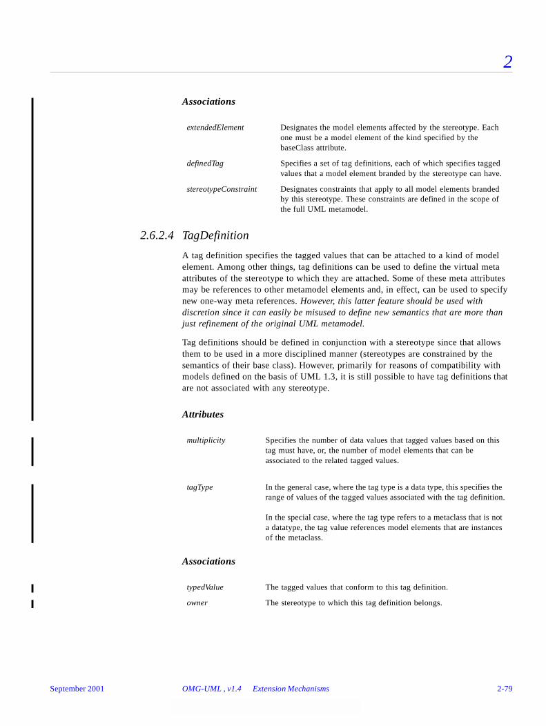
2
Associations
2.6.2.4 TagDefinition
A tag definition specifies the tagged values that can be attached to a kind of model element. Among other things, tag definitions can be used to define the virtual meta attributes of the stereotype to which they are attached. Some of these meta attributes may be references to other metamodel elements and, in effect, can be used to specify new one-way meta references. However, this latter feature should be used with discretion since it can easily be misused to define new semantics that are more than just refinement of the original UML metamodel.
Tag definitions should be defined in conjunction with a stereotype since that allows them to be used in a more disciplined manner (stereotypes are constrained by the semantics of their base class). However, primarily for reasons of compatibility with models defined on the basis of UML 1.3, it is still possible to have tag definitions that are not associated with any stereotype.
Attributes
Associations
extendedElement Designates the model elements affected by the stereotype. Each one must be a model element of the kind specified by the baseClass attribute.
definedTag Specifies a set of tag definitions, each of which specifies tagged values that a model element branded by the stereotype can have.
stereotypeConstraint Designates constraints that apply to all model elements branded by this stereotype. These constraints are defined in the scope of the full UML metamodel.
multiplicity Specifies the number of data values that tagged values based on this tag must have, or, the number of model elements that can be associated to the related tagged values.
tagType In the general case, where the tag type is a data type, this specifies the range of values of the tagged values associated with the tag definition.
In the special case, where the tag type refers to a metaclass that is not a datatype, the tag value references model elements that are instances of the metaclass.
typedValue The tagged values that conform to this tag definition.
owner The stereotype to which this tag definition belongs.
September 2001 OMG-UML , v1.4 Extension Mechanisms 2-79
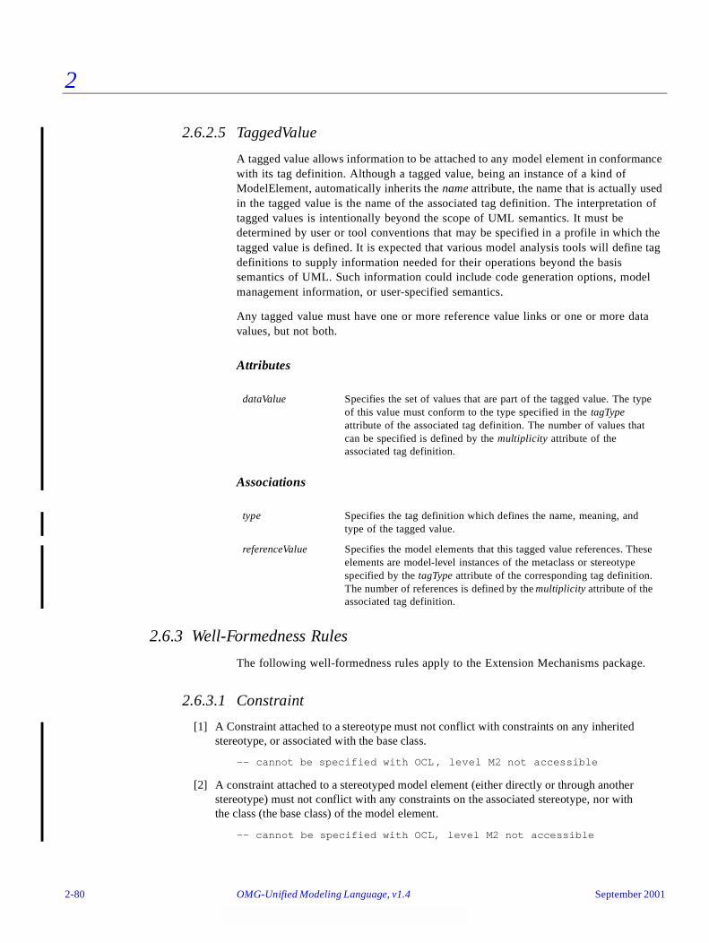
2
2.6.2.5 TaggedValue
A tagged value allows information to be attached to any model element in conformance with its tag definition. Although a tagged value, being an instance of a kind of ModelElement, automatically inherits the name attribute, the name that is actually used in the tagged value is the name of the associated tag definition. The interpretation of tagged values is intentionally beyond the scope of UML semantics. It must be determined by user or tool conventions that may be specified in a profile in which the tagged value is defined. It is expected that various model analysis tools will define tag definitions to supply information needed for their operations beyond the basis semantics of UML. Such information could include code generation options, model management information, or user-specified semantics.
Any tagged value must have one or more reference value links or one or more data values, but not both.
Attributes
Associations
2.6.3 Well-Formedness Rules
The following well-formedness rules apply to the Extension Mechanisms package.
2.6.3.1 Constraint
[1] A Constraint attached to a stereotype must not conflict with constraints on any inheritedstereotype, or associated with the base class.
-- cannot be specified with OCL , level M2 not accessible
[2] A constraint attached to a stereotyped model element (either directly or through anotherstereotype) must not conflict with any constraints on the associated stereotype, nor withthe class (the base class) of the model element.
-- cannot be specified with OCL, level M2 not accessible
dataValue Specifies the set of values that are part of the tagged value. The type of this value must conform to the type specified in the tagType attribute of the associated tag definition. The number of values that can be specified is defined by the multiplicity attribute of the associated tag definition.
type Specifies the tag definition which defines the name, meaning, and type of the tagged value.
referenceValue Specifies the model elements that this tagged value references. These elements are model-level instances of the metaclass or stereotype specified by the tagType attribute of the corresponding tag definition. The number of references is defined by the multiplicity attribute of the associated tag definition.
2-80 OMG-Unified Modeling Language, v1.4 September 2001

2
[3] A constraint attached to a stereotype will apply to all model elements branded by thatstereotype and must not conflict with any constraints on the attached branding stereotype,nor with the class (the base class) of the model element.
-- cannot be specified with OCL, level M2 not accessible
2.6.3.2 ModelElement
[1] Tags associated with a model element (directly via a property list or indirectly via astereotype) must not clash with any meta attributes associated with the model element.
-- cannot be specified with OCL, level M2 not accessible
[2] A model element must have at most one tagged value with a given tag name.
self.taggedValue->forAll(t1, t2 : TaggedValue |
t1.type.name = t2.type.name implies t1 = t2)
[3] A stereotype cannot extend itself.
self.stereotype->excludes(self)
2.6.3.3 Stereotype
[1] Stereotype names must not clash with any base class names.
Stereotype.allInstances->forAll(st | st.baseClass <> self.name)
[2] The base class name must be provided.
Set {self.baseClass}->notEmpty
[3] Tag names attached to a stereotype must not clash with M2 meta-attributenamespace of the appropriate base class element, nor with tag definition names of any inherited stereotype.
-- cannot be specified with OCL, level M2 not accessible
[4] The base class of a stereotype must be the same or a subclass of the base class of parentstereotypes.
-- cannot be specified with OCL, level M2 not accessible
[5] All stereotype definitions must be contained either directly or transitively in a profilepackage.
findProfile(self)->notEmpty
Additional Operations
[1] The find profile operation returns either the single-element set containing profile packagein which the model element is defined or an empty set if the element is not contained inany profile.
findProfile (me : ModelElement) : Set (Package)
if (me.namespace->notEmpty) then
if (me.namespace.oclIsKindOf(Package) and
September 2001 OMG-UML , v1.4 Extension Mechanisms 2-81
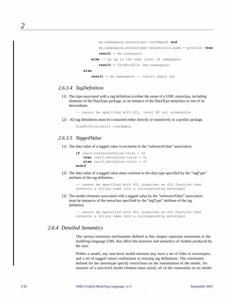
2
me.namespace.stereotype->notEmpty) and
me.namespace.stereotype->exists(s|s.name = profile) then
result = me.namespace
else -- go up to the next level of namespace
result = findProfile (me.namespace)
else
result = me.namespace -- return empty set
2.6.3.4 TagDefinition
[1] The type associated with a tag definition is either the name of a UML metaclass, includingelements of the DataType package, or an instance of the DataType metaclass or one of itsdescendants.
-- cannot be specified with OCL, level M2 not accessible
[2] All tag definitions must be contained either directly or transitively in a profile package.
findProfile(self)->notEmpty
2.6.3.5 TaggedValue
[1] The data value of a tagged value is exclusive to the “referenceValue” association.
if (self.referenceValue->size > 0) then (self.dataValue->size = 0)else (self.dataValue->size > 0)
endif
[2] The data value of a tagged value must conform to the data type specified by the “tagType”attribute of the tag definition.
-- cannot be specified with OCL (requires an OCL function that converts a string name into a corresponding metatype)
[3] The model elements associated with a tagged value by the “referenceValue” associationmust be instances of the metaclass specified by the “tagType” attribute of the tagdefinition.
-- cannot be specified with OCL (requires an OCL function that converts a string name into a corresponding metatype)
2.6.4 Detailed Semantics
The various extension mechanisms defined in this chapter represent extensions to the modeling language UML that affect the structure and semantics of models produced by the user.
Within a model, any user-level model element may have a set of links to stereotypes, and a set of tagged values conformant to existing tag definitions. The constraints defined for the stereotype specify restrictions on the instantiation of the model. An instance of a user-level model element must satisfy all of the constraints on its model
2-82 OMG-Unified Modeling Language, v1.4 September 2001

2
element for the model to be well-formed. Evaluation of constraints is to be performed when the relevant portion of the system is “stable,” that is, after the completion of any internal operations when it is waiting for external events. In general, constraints are written in any language that can adequately specify the desired constraints, such as OCL, C++, or natural language. The interpretation of the constraints must be specified by the constraint language.
A stereotype refers to a base class, which is a class in the UML metamodel (not a user-level modeling element) such as Class, Association, Refinement, etc. A stereotype may be a subclass of one or more existing stereotypes. In that case, it inherits their constraints and tag definitions and may add additional ones of its own. In principle, a stereotype inherits the base class value of its parent, if one exists (this is expressed as a constraint on these values). The modeler may refine this to any subclass of that base class. For instance, if a stereotype s with a base class b is defined, then a stereotype t that has s as its superclass has either b or any subclass of b as its base class value. If a stereotype has multiple superclasses, then all of these superclasses must be derived from a single common superclass. In that case, the base class of the subclass is equivalent to the most specific parent stereotype, or a subclass of that. For instance, if a stereotype s has supertypes t and u with base classes “Classifier” and “Class” respectively, then the base class of s is “Class” or any subclass of “Class” in UML.
If a model element is branded by an attached stereotype, then the UML base class of the model element must be the base class specified by the stereotype or one of the subclasses of that base class. Any constraints on the stereotype are implicitly attached to the model element. Any tag definitions belonging to the stereotype will serve as specifications for tagged values associated to the model element. If the stereotype is a subclass of one or more stereotypes, then any constraints or tag definitions from those stereotypes also apply to the model element (because they are inherited by this stereotype). If there are any conflicts among the multiple constraints and tag definitions (inherited or directly specified), then the model is ill formed, as is the case with general specialization hierarchies.
2.6.5 Notes
Backward compatibility of profiles with UML 1.3 has been addressed by maintaining the basic UML 1.3 extension features while adding new features that can be optionally exploited. There are two areas where backward compatibility has been carefully considered. First, although it is generally recommended that tags should be defined in the context of a stereotype, they may still be defined independently as was the case with UML 1.3. Second, although it is generally recommended that tag definitions should be typed, they may still be defined with type declared String; that is, they are effectively not typed.
UML 1.4 compliant tools are expected to make use of the ability to type tags, and to provide conversion utilities for models based on earlier versions of UML. It is important to note, however, that older models that contain tags declared to be of type String should still work correctly, since String continues to be a standard UML datatype.
The following are some typical examples of stereotypes and tag definitions:
September 2001 OMG-UML , v1.4 Extension Mechanisms 2-83
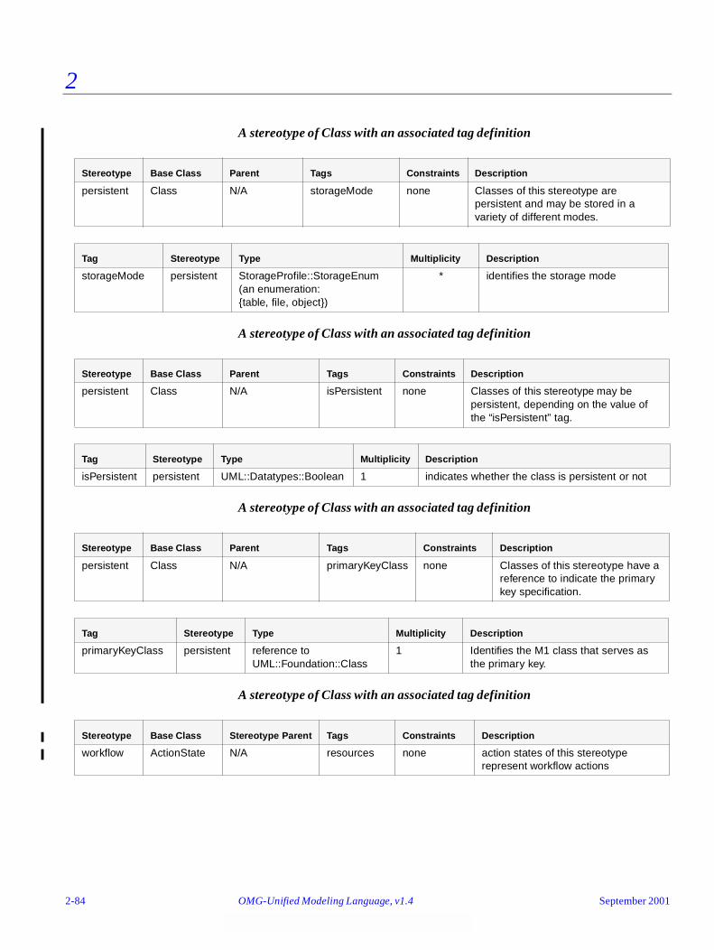
2
A stereotype of Class with an associated tag definition
A stereotype of Class with an associated tag definition
A stereotype of Class with an associated tag definition
A stereotype of Class with an associated tag definition
Stereotype Base Class Parent Tags Constraints Description
persistent Class N/A storageMode none Classes of this stereotype are persistent and may be stored in a variety of different modes.
Tag Stereotype Type Multiplicity Description
storageMode persistent StorageProfile::StorageEnum(an enumeration:{table, file, object})
* identifies the storage mode
Stereotype Base Class Parent Tags Constraints Description
persistent Class N/A isPersistent none Classes of this stereotype may be persistent, depending on the value of the “isPersistent” tag.
Tag Stereotype Type Multiplicity Description
isPersistent persistent UML::Datatypes::Boolean 1 indicates whether the class is persistent or not
Stereotype Base Class Parent Tags Constraints Description
persistent Class N/A primaryKeyClass none Classes of this stereotype have a reference to indicate the primary key specification.
Tag Stereotype Type Multiplicity Description
primaryKeyClass persistent reference to UML::Foundation::Class
1 Identifies the M1 class that serves as the primary key.
Stereotype Base Class Stereotype Parent Tags Constraints Description
workflow ActionState N/A resources none action states of this stereotype represent workflow actions
2-84 OMG-Unified Modeling Language, v1.4 September 2001
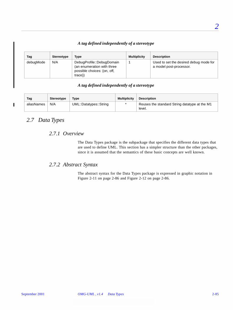
2
A tag defined independently of a stereotype
A tag defined independently of a stereotype
2.7 Data Types
2.7.1 Overview
The Data Types package is the subpackage that specifies the different data types that are used to define UML. This section has a simpler structure than the other packages, since it is assumed that the semantics of these basic concepts are well known.
2.7.2 Abstract Syntax
The abstract syntax for the Data Types package is expressed in graphic notation in Figure 2-11 on page 2-86 and Figure 2-12 on page 2-86.
Tag Stereotype Type Multiplicity Description
debugMode N/A DebugProfile::DebugDomain(an enumeration with three possible choices: {on, off, trace})
1 Used to set the desired debug mode for a model post-processor.
Tag Stereotype Type Multiplicity Description
aliasNames N/A UML::Datatypes::String * Reuses the standard String datatype at the M1 level.
September 2001 OMG-UML , v1.4 Data Types 2-85
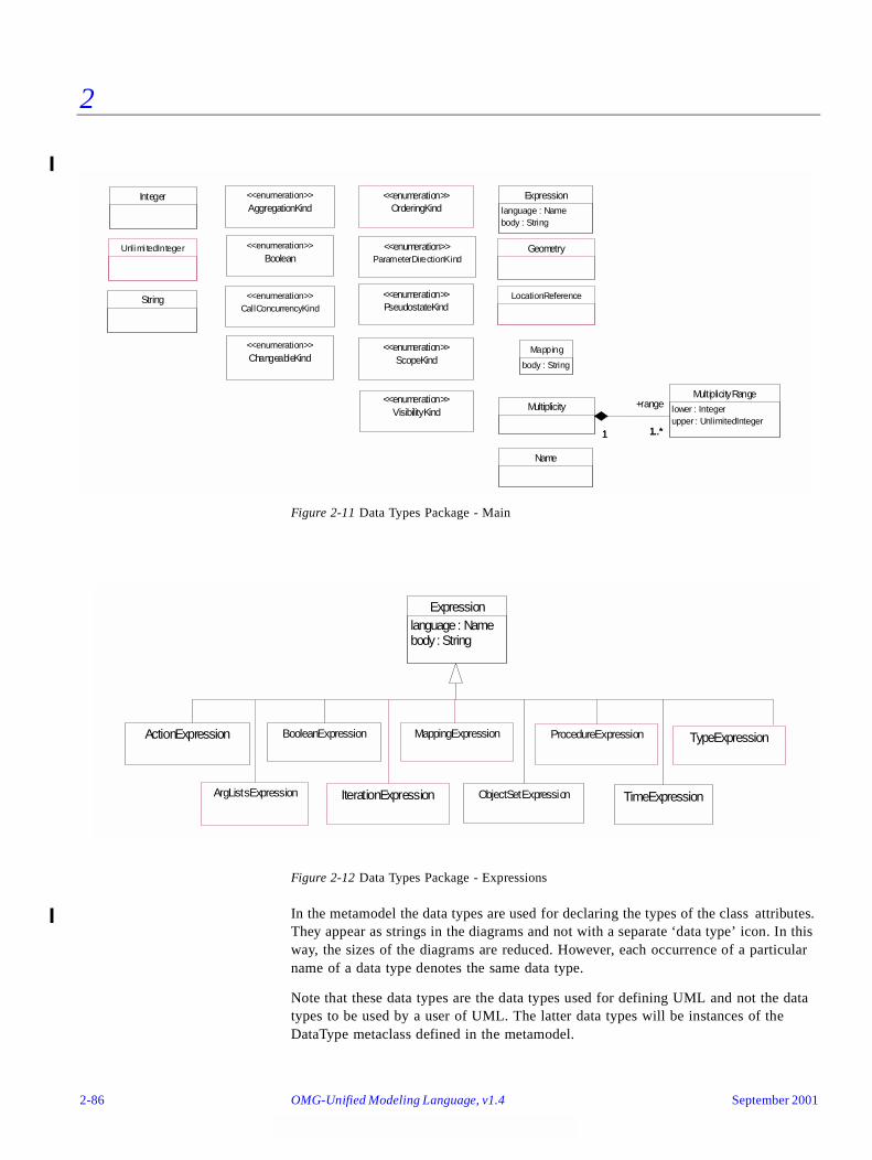
2
Figure 2-11 Data Types Package - Main
Figure 2-12 Data Types Package - Expressions
In the metamodel the data types are used for declaring the types of the class attributes. They appear as strings in the diagrams and not with a separate ‘data type’ icon. In this way, the sizes of the diagrams are reduced. However, each occurrence of a particular name of a data type denotes the same data type.
Note that these data types are the data types used for defining UML and not the data types to be used by a user of UML. The latter data types will be instances of the DataType metaclass defined in the metamodel.
AggregationKind<<enumeration>>
Boolean<<enumeration>>
ChangeableKind<<enumeration>>
Expression
language : Namebody : String
Name
Integer
ParameterDirectionKind<<enumeration>>
ScopeKind<<enumeration>>
String
VisibilityKind<<enumeration>>
PseudostateKind<<enumeration>>
CallConcurrencyKind<<enumeration>>
MultiplicityRange
lower : Integerupper : UnlimitedInteger
Multiplicity
1..*1
+range
1..*1
Mapping
body : String
Unlimi tedInteger
LocationReference
OrderingKind<<enumeration>>
Geometry
IterationExpression
BooleanExpression
Expressionlanguage : Namebody : String
ObjectSetExpression TimeExpression
ActionExpression TypeExpression
ArgListsExpression
MappingExpression ProcedureExpression
2-86 OMG-Unified Modeling Language, v1.4 September 2001

2
2.7.2.1 ActionExpression
An expression whose evaluation results in the performance of an action.
2.7.2.2 AggregationKind
An enumeration that denotes what kind of aggregation an Association is. When placed on a target end, specifies the relationship of the target end to the source end. AggregationKind defines an enumeration whose values are:
2.7.2.3 ArgListsExpression
In the metamodel ArgListsExpression defines a statement that will result in a set of object lists when it is evaluated.
2.7.2.4 Boolean
In the metamodel Boolean defines an enumeration that denotes a logicial condition. Its enumeration literals are:
2.7.2.5 BooleanExpression
In the metamodel BooleanExpression defines a statement that will evaluate to an instance of Boolean when it is evaluated.
none The end is not an aggregate.
aggregate The end is an aggregate; therefore, the other end is a part and must have the aggregation value of none. The part may be contained in other aggregates.
composite The end is a composite; therefore, the other end is a part and must have the aggregation value of none. The part is strongly owned by the composite and may not be part of any other composite.
true The Boolean condition is satisfied.
false The Boolean condition is not satisfied.
September 2001 OMG-UML , v1.4 Data Types 2-87
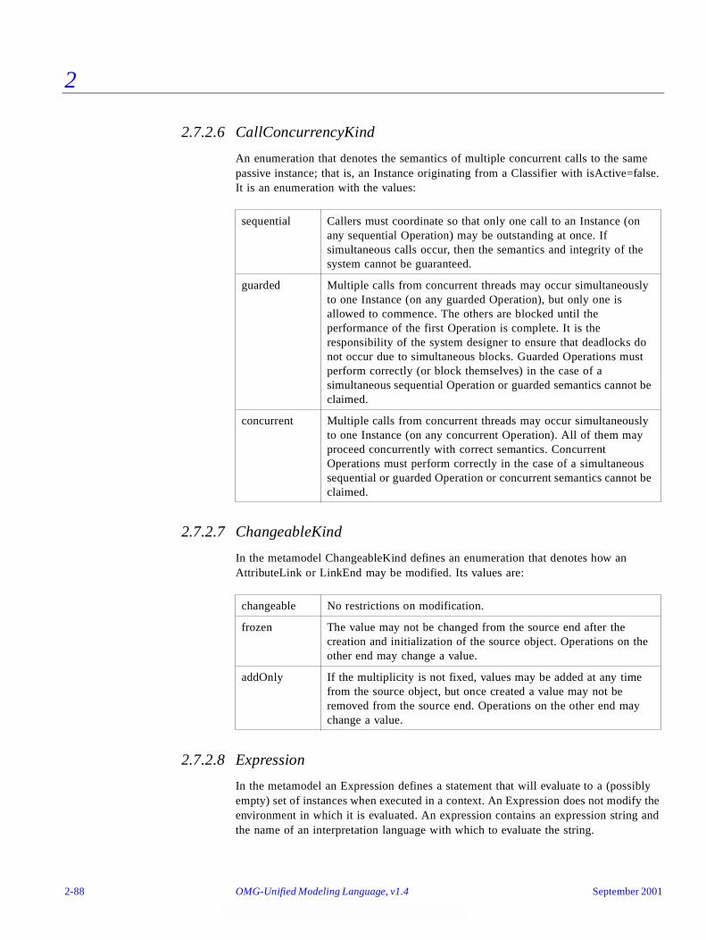
2
2.7.2.6 CallConcurrencyKind
An enumeration that denotes the semantics of multiple concurrent calls to the same passive instance; that is, an Instance originating from a Classifier with isActive=false. It is an enumeration with the values:
2.7.2.7 ChangeableKind
In the metamodel ChangeableKind defines an enumeration that denotes how an AttributeLink or LinkEnd may be modified. Its values are:
2.7.2.8 Expression
In the metamodel an Expression defines a statement that will evaluate to a (possibly empty) set of instances when executed in a context. An Expression does not modify the environment in which it is evaluated. An expression contains an expression string and the name of an interpretation language with which to evaluate the string.
sequential Callers must coordinate so that only one call to an Instance (on any sequential Operation) may be outstanding at once. If simultaneous calls occur, then the semantics and integrity of the system cannot be guaranteed.
guarded Multiple calls from concurrent threads may occur simultaneously to one Instance (on any guarded Operation), but only one is allowed to commence. The others are blocked until the performance of the first Operation is complete. It is the responsibility of the system designer to ensure that deadlocks do not occur due to simultaneous blocks. Guarded Operations must perform correctly (or block themselves) in the case of a simultaneous sequential Operation or guarded semantics cannot be claimed.
concurrent Multiple calls from concurrent threads may occur simultaneously to one Instance (on any concurrent Operation). All of them may proceed concurrently with correct semantics. Concurrent Operations must perform correctly in the case of a simultaneous sequential or guarded Operation or concurrent semantics cannot be claimed.
changeable No restrictions on modification.
frozen The value may not be changed from the source end after the creation and initialization of the source object. Operations on the other end may change a value.
addOnly If the multiplicity is not fixed, values may be added at any time from the source object, but once created a value may not be removed from the source end. Operations on the other end may change a value.
2-88 OMG-Unified Modeling Language, v1.4 September 2001
2
Attributes
Predefined language names include the following:
In general, a language name should be spelled and capitalized exactly as it appears in the document defining the language. For example, use COBOL, not Cobol; use Ada, not ADA; use PostScript, not Postscript. In other words, spell it correctly.
2.7.2.9 Geometry
An uninterpreted type used to describe the geometrical shape of icons, such as those that may be attached to stereotypes. The details of this specification are not currently part of UML and must therefore be supplied by the implementation of a model editing tool, with the understanding that they will likely be tool-specific. This type is therefore not actually defined in the metamodel but is used only as the type of attributes.
2.7.2.10 Integer
In the metamodel, Integer is a classifier element that is an instance of Primitive, representing the predefined type of integers. An instance of Integer an element in the (infinite) set of integers (…-2, -1, 0, 1, 2…).
2.7.2.11 IterationExpression
In the metamodel IterationExpression defines a string that will evaluate to an iteration control construct in the interpretation language.
2.7.2.12 LocationReference
Designates a position within a behavior sequence for the insertion of an extension use case. May be a line or range of lines in code, or a state or set of states in a state machine, or some other means in a different kind of specification.
language Names the language in which the expression body is represented. The interpretation of the expression depends on the language. If the language name is omitted, no interpretation for the expression can be assumed by UML.
body The text of the expression expressed in the given language.
OCL The Object Constraint Language (see the chapter “Object Constraint Language Specification” in this document).
(The empty string) This represents a natural-language statement. As such, it is obviously intended for human information rather than formal specification.
September 2001 OMG-UML , v1.4 Data Types 2-89
2
2.7.2.13 Mapping
In the metamodel a Mapping is an expression that is used for mapping ModelElements. For exchange purposes, it should be represented as a String.
Attributes
2.7.2.14 MappingExpression
An expression that evaluates to a mapping.
2.7.2.15 Multiplicity
In the metamodel a Multiplicity defines a non-empty set of non-negative integers. A set that only contains zero ({0}) is not considered a valid Multiplicity. Every Multiplicity has at least one corresponding String representation.
2.7.2.16 MultiplicityRange
In the metamodel a MultiplicityRange defines a range of integers. The upper bound of the range cannot be below the lower bound. The lower bound must be a nonnegative integer. The upper bound must be a nonnegative integer or the special value unlimited, which indicates there is no upper bound on the range.
2.7.2.17 Name
In the metamodel a Name defines a token that is used for naming ModelElements. A name is represented as a String.
2.7.2.18 ObjectSetExpression
In the metamodel ObjectSetExpression defines a statement that will evaluate to a set of instances when it is evaluated. ObjectSetExpressions are commonly used to designate the target instances in an Action. The expression may be the reserved word “all” when used as the target of a SendAction. It evaluates to all the instances that can receive the signal, as determined by the underlying runtime system.
2.7.2.19 OrderingKind
Defines an enumeration that specifies how the elements of a set are arranged. Used in conjunction with elements that have a multiplicity in cases when the multiplicity value is greater than one. The ordering must be determined and maintained by operations that
body A string describing the mapping. The format of the mapping is currently unspecified in UML.
2-90 OMG-Unified Modeling Language, v1.4 September 2001

2
modify the set. The intent is that the set of enumeration literals be open for new values to be added by tools for purposes of design, code generation, etc. For example, a value of sorted might be used for a design specification.
Values are:
2.7.2.20 ParameterDirectionKind
In the metamodel ParameterDirectionKind defines an enumeration that denotes if a Parameter is used for supplying an argument and/or for returning a value. The enumeration values are:
2.7.2.21 ProcedureExpression
In the metamodel ProcedureExpression defines a statement that will result in a change to the values of its environment when it is evaluated.
unordered The elements of the set have no inherent ordering.
ordered The elements of the set have a sequential ordering.
Other possibilities (such as sorted) may be defined later by declaring additional keywords. As with user-defined stereotypes, this would be a private extension supported by particular editing tools.
in An input Parameter (may not be modified).
out An output Parameter (may be modified to communicate information to the caller).
inout An input Parameter that may be modified.
return A return value of a call.
September 2001 OMG-UML , v1.4 Data Types 2-91
2
2.7.2.22 PseudostateKind
In the metamodel, PseudostateKind defines an enumeration that discriminates the kind of Pseudostate. See Section 2.12.2.7, “PseudoState,” on page 2-151 for details. The enumeration values are:
2.7.2.23 ScopeKind
In the metamodel ScopeKind defines an enumeration that denotes whether a feature belongs to individual instances or an entire classifier. Its values are:
choice Splits an incoming transition into several disjoint outgoing transitions. Each outgoing transition has a guard condition that is evaluated after prior actions on the incoming path have been completed. At least one outgoing transition must be enabled or the model is ill formed.
deepHistory When reached as the target of a transition, restores the full state configuration that was active just before the enclosing composite state was last exited.
fork Splits an incoming transition into several concurrent outgoing transitions. All of the transitions fire together.
initial The default target of a transition to the enclosing composite state.
join Merges transitions from concurrent regions into a single outgoing transition. All the transitions fire together.
junction Chains together transitions into a single run-to-completion path. May have multiple input and/or output transitions. Each complete path involving a junction is logically independent and only one such path fires at one time. May be used to construct branches and merges.
shallowHistory When reached as the target of a transition, restores the state within the enclosing composite state that was active just before the enclosing state was last exited. Does not restore any substates of the last active state.
instance The feature pertains to Instances of a Classifier. For example, it is a distinct Attribute in each Instance or an Operation that works on an Instance.
classifier The feature pertains to an entire Classifier. For example, it is an Attribute shared by the entire Classifier or an Operation that works on the Classifier, such as a creation operation.
2-92 OMG-Unified Modeling Language, v1.4 September 2001
2
2.7.2.24 String
In the metamodel String is a classifier element that is an instance of Primitive. An instance of String defines a piece of text.
2.7.2.25 TimeExpression
In the metamodel TimeExpression defines a statement that will define the time of occurrence of an event. The specific format of time expressions is not specified here and is subject to implementation considerations.
2.7.2.26 TypeExpression
In the metamodel TypeExpression is the encoding of a programming language type in the interpretation language. It is used within a ProgrammingLanguageDataType.
2.7.2.27 UnlimitedInteger
In the metamodel, UnlimitedInteger is a classifier element that is an instance of Primitive. It defines a data type whose range is the nonnegative integers augmented by the special value “unlimited.” It is used for the upper bound of multiplicities.
2.7.2.28 Uninterpreted
In the metamodel an Uninterpreted is a blob, the meaning of which is domain-specific and therefore not defined in UML.
2.7.2.29 VisibilityKind
In the metamodel VisibilityKind defines an enumeration that denotes how the element to which it refers is seen outside the enclosing name space. Its values are:
Part 3 - Behavioral ElementsThis Behavioral Elements package is the language superstructure that specifies the dynamic behavior or models. The Behavioral Elements package is decomposed into the following subpackages: Common Behavior, Collaborations, Use Cases, State Machines, and Activity Graphs.
public Other elements may see and use the target element.
protected Descendants of the source element may see and use the target element.
private Only the source element may see and use the target element.
package Elements declared in the same package as the target element may see and use the target element.
September 2001 OMG-UML , v1.4 Data Types 2-93

2
2.8 Behavioral Elements Package
Common Behavior specifies the core concepts required for behavioral elements. The Collaborations package specifies a behavioral context for using model elements to accomplish a particular task. The Use Case package specifies behavior using actors and use cases. The State Machines package defines behavior using finite-state transition systems. The Activity Graphs package defines a special case of a state machine that is used to model processes.
Figure 2-13 Behavioral Elements Package
2.9 Common Behavior
2.9.1 Overview
The Common Behavior package is the most fundamental of the subpackages that compose the Behavioral Elements package. It specifies the core concepts required for dynamic elements and provides the infrastructure to support Collaborations, State Machines, and Use Cases.
The following sections describe the abstract syntax, well-formedness rules, and semantics of the Common Behavior package.
Use Cases State MachinesCollaborations
Com m on Behavior
Ac tivity Grap hs
2-94 OMG-Unified Modeling Language, v1.4 September 2001
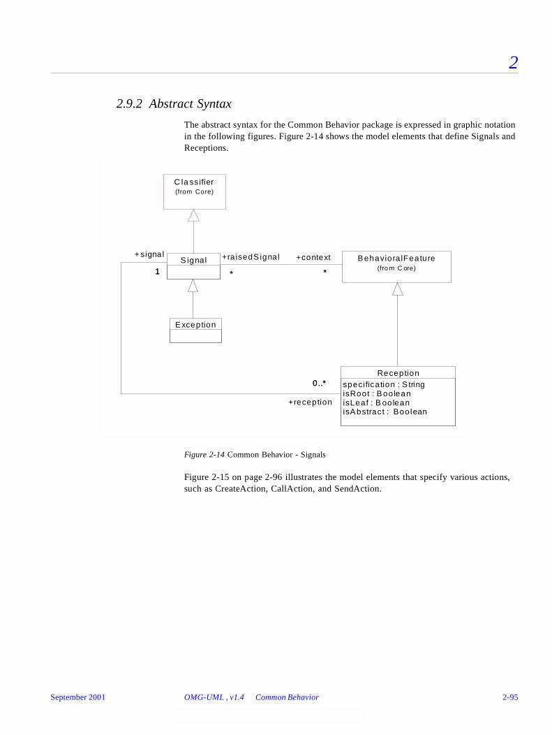
2
2.9.2 Abstract Syntax
The abstract syntax for the Common Behavior package is expressed in graphic notation in the following figures. Figure 2-14 shows the model elements that define Signals and Receptions.
Figure 2-14 Common Behavior - Signals
Figure 2-15 on page 2-96 illustrates the model elements that specify various actions, such as CreateAction, CallAction, and SendAction.
Exception
Receptionspecification : S tringisRoot : BooleanisLeaf : B ooleanisAbstract : Boolean
Behaviora lFeature(fro m C ore)
S ignal1
0..*
+ signal
1
+reception
0..*
**
+context
*
+ra isedS ignal
*
C la ss ifier(from Core)
September 2001 OMG-UML , v1.4 Common Behavior 2-95
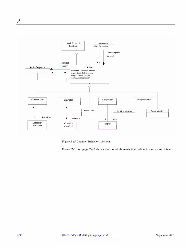
2
Figure 2-15 Common Behavior - Actions
Figure 2-16 on page 2-97 shows the model elements that define Instances and Links.
DestroyAction
UninterpretedAction
ModelElement(from Core)
CreateAction
Classifier(from Core)
0..*
1
0..*
+instantiation1
ReturnAction TerminateAction
CallAction
Operation(from Core)
*
1
*
+operation1
SendAction
Signal
*
1
*
+signal1
Argumentvalue : Expression
ActionSequence Actionrecurrence : IterationExpressiontarget : ObjectSetExpressionisAsynchronous : Booleanscript : ActionExpression
*
0..1
+actualArgument*
{ordered}
0..1
0..1 0..*0..1
+action
0..*
{ordered}
2-96 OMG-Unified Modeling Language, v1.4 September 2001
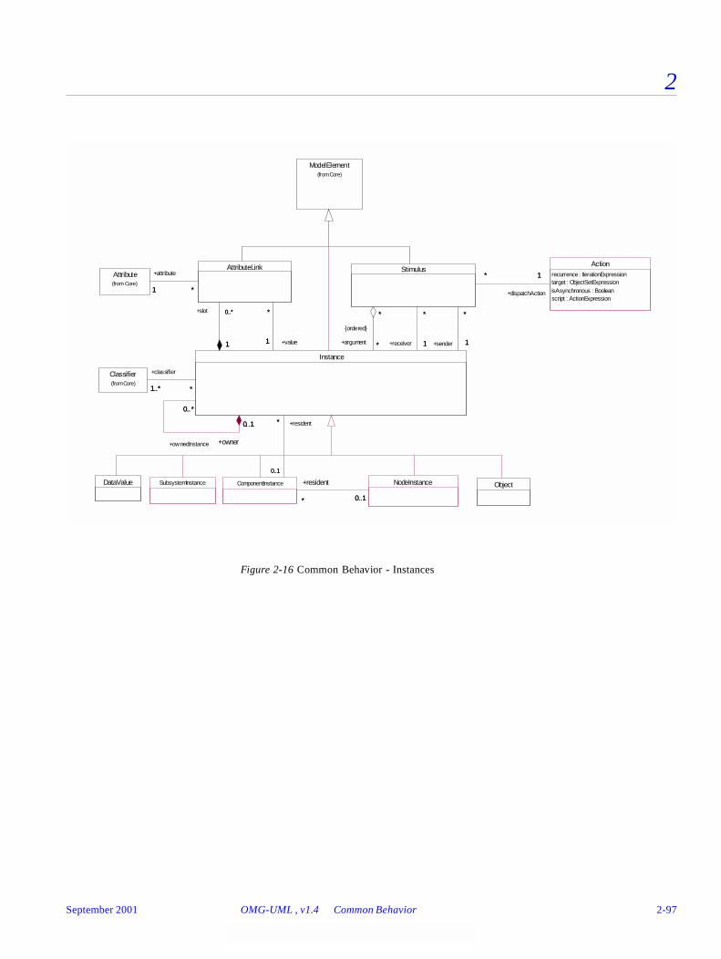
2
Figure 2-16 Common Behavior - Instances
DataValue Object
ModelElement(from Core)
NodeInstance
Actionrecurrence : IterationExpressiontarget : ObjectSetExpressionisAsynchronous : Booleanscript : ActionExpression
Attribute(from Core)
ComponentInstance
* 0..1
+resident
* 0..1
Stimulus1*
+dispatchAction
1*
Classifier(from Core)
AttributeLink
*1 *
+attribute
1
Instance
*
0..1
+resident*
0..1
*
*
*
+argument *
{ordered}
*
1
*
+sender 11
*
+receiver 1
*
1..* *
+classifier
1..* *
1
0..*
1
+slot 0..* *
1
*
+value1
0..*
0..1
+ownedInstance
0..*
+owner
0..1
SubsystemInstance
September 2001 OMG-UML , v1.4 Common Behavior 2-97
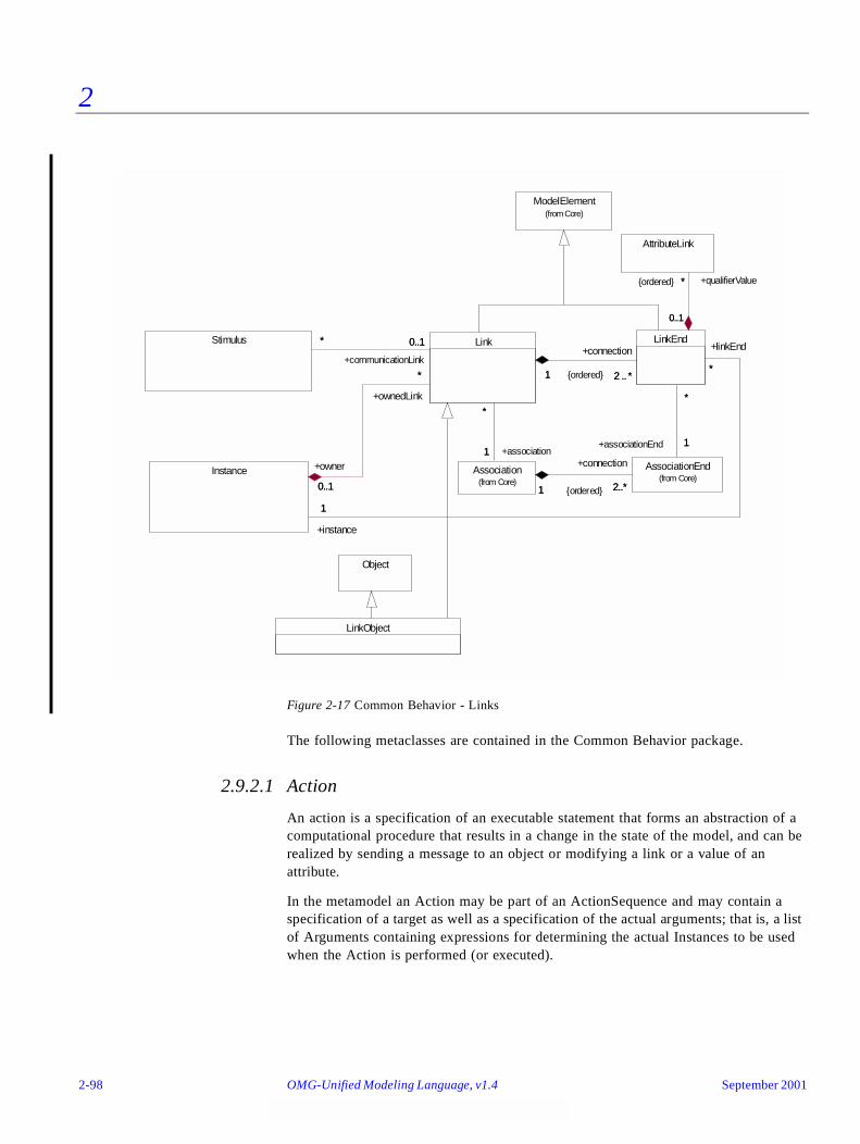
2
Figure 2-17 Common Behavior - Links
The following metaclasses are contained in the Common Behavior package.
2.9.2.1 Action
An action is a specification of an executable statement that forms an abstraction of a computational procedure that results in a change in the state of the model, and can be realized by sending a message to an object or modifying a link or a value of an attribute.
In the metamodel an Action may be part of an ActionSequence and may contain a specification of a target as well as a specification of the actual arguments; that is, a list of Arguments containing expressions for determining the actual Instances to be used when the Action is performed (or executed).
LinkObject
Object
ModelElement(from Core)
AssociationEnd(from Core)
AttributeLink
Association(from Core)
Stimulus LinkEndLink
Instance
+associationEnd 1
+qualifierValue*{ordered}
2..*1
+connection
2..*1 {ordered}
+association1
*
*
1
*
0..10..1
*
+linkEnd
*
*
1
*
+communicationLink
0..1* 0..1
1 2 .. *1
+connection
2 .. *{ordered}
+ownedLink
*
+instance
11
*
+owner
0..1
*
0..1
2-98 OMG-Unified Modeling Language, v1.4 September 2001
2
The target metaattribute is of type ObjectSetExpression which, when executed, resolves into zero or more specific Instances that are the intended target of the Action, like a receiver of a dispatched Signal. The recurrence metaattribute specifies how the target set is iterated when the action is executed. It is not defined within UML if the action is applied sequentially or in parallel to the target instances.
Action is an abstract metaclass.
Attributes
Associations
2.9.2.2 ActionSequence
An action sequence is a collection of actions.
In the metamodel an ActionSequence is an Action, which is an aggregation of other Actions. It describes the behavior of the owning State or Transition.
Associations
2.9.2.3 Argument
An argument is an expression describing how to determine the actual values passed in a dispatched request.
In the metamodel an Argument is a composite part of an Action and contains a metaattribute value of type Expression. It states how the actual argument is determined when the owning Action is executed.
Attributes
isAsynchronous Indicates if a dispatched Stimulus is asynchronous or not.
recurrence An Expression stating how many times the Action should be performed.
script An ActionExpression describing the effects of the Action.
target An ObjectSetExpression that determines the target of the Action.
actualArgument A sequence of Expressions that determines the actual arguments needed when evaluating the Action.
action A sequence of Actions performed sequentially as an atomic unit.
value An Expression determining the actual Instance when evaluated.
September 2001 OMG-UML , v1.4 Common Behavior 2-99
2
2.9.2.4 AttributeLink
An attribute link is a named slot in an instance, which holds the value of an attribute.
In the metamodel AttributeLink is a piece of the state of an Instance and holds the value of an Attribute.
Associations
2.9.2.5 CallAction
A call action is an action resulting in an invocation of an operation on an instance. A call action can be synchronous or asynchronous, indicating whether the operation is invoked synchronously or asynchronously.
In the metamodel the CallAction is an Action. The designated Instance or set of Instances is specified via the target expression, and the actual arguments are designated via the argument association inherited from Action. The Operation to be invoked is specified by the associated Operation.
Attributes
Associations
2.9.2.6 ComponentInstance
A component instance is an instance of a component that resides on a node instance. A component instance may have a state.
In the metamodel a ComponentInstance is an Instance that originates from a Component. It may be associated with a set of Instances, and may reside on a NodeInstance.
value The Instance that is the value of the AttributeLink.
attribute The Attribute from which the AttributeLink originates.
isAsynchronous (inherited from Action) Indicates if a dispatched operation is asynchronous or not.
• False - indicates that the caller waits for the completion of the execution of the operation.
• True - Indicates that the caller does not wait for the completion of the execution of the operation but continues immediately.
operation The operation that will be invoked when the Action is executed.
2-100 OMG-Unified Modeling Language, v1.4 September 2001
2
Associations
2.9.2.7 CreateAction
A create action is an action resulting in the creation of an instance of some classifier.
In the metamodel the CreateAction is an Action. The Classifier to be instantiated is designated by the instantiation association of the CreateAction. A CreateAction has no target instance.
Associations
2.9.2.8 DestroyAction
A destroy action is an action that results in the destruction of an object specified in the action.
In the metamodel a DestroyAction is an Action. The designated object is specified by the target association of the Action.
2.9.2.9 DataValue
A data value is an instance with no identity.
In the metamodel DataValue is a child of Instance that cannot change its state; that is, all Operations that are applicable to it are pure functions or queries. DataValues are typically used as attribute values.
2.9.2.10 Exception
An exception is a signal raised by behavioral features typically in case of execution faults.
In the metamodel Exception is derived from Signal. An Exception is associated with the BehavioralFeatures that raise it.
Associations
resident A collection of Instances that exist inside the ComponentInstance.
instantiation The Classifier of which an Instance will be created of when the CreateAction is performed.
context (Inherited from Signal) The set of BehavioralFeatures that raise the exception.
September 2001 OMG-UML , v1.4 Common Behavior 2-101

2
2.9.2.11 Instance
The instance construct defines an entity to which a set of operations can be applied and which has a state that stores the effects of the operations.
In the metamodel Instance is connected to at least one Classifier that declares its structure and behavior. It has a set of attribute values and is connected to a set of Links, both sets matching the definitions of its Classifiers. The two sets implement the current state of the Instance. An Instance may also own other Instances or Links.
Instance is an abstract metaclass.
Associations
Standard Constraints
Tagged Values
2.9.2.12 Link
The link construct is a connection between instances.
In the metamodel Link is an instance of an Association. It has a set of LinkEnds that matches the set of AssociationEnds of the Association. A Link defines a connection between Instances.
slot The set of AttributeLinks that holds the attribute values of the Instance.
linkEnd The set of LinkEnds of the connected Links that are attached to the Instance.
classifier The set of Classifiers that declare the structure of the Instance.
ownedInstance The set of Instances that are owned by the Instance.
ownedLink The set of Links that are owned by the Instance.
owner Specifies the Instance that owns the Instance.
destroyed Destroyed is a constraint applied to an instance, specifying that the instance is destroyed during the execution.
new New is a constraint applied to an instance, specifying that the instance is created during the execution.
transient Transient is a constraint applied to an instance, specifying that the instance is created and destroyed during the execution.
persistent Persistence denotes the permanence of the state of the instance, marking it as transitory (its state is destroyed when the instance is destroyed) or persistent (its state is not destroyed when the instance is destroyed).
2-102 OMG-Unified Modeling Language, v1.4 September 2001
2
Associations
Standard Constraints
2.9.2.13 LinkEnd
A link end is an end point of a link. In the metamodel LinkEnd is the part of a Link that connects to an Instance. It corresponds to an AssociationEnd of the Link’s Association.
Associations
Stereotypes
association The Association that is the declaration of the link.
connection The tuple of LinkEnds that constitute the Link.
owner Specifies the Instance that owns the Link.
destroyed Destroyed is a constraint applied to a link, specifying that the link is destroyed during the execution.
new New is a constraint applied to a link, specifying that the link is created during the execution.
transient Transient is a constraint applied to a link, specifying that the link is created and destroyed during the execution.
associationEnd The AssociationEnd that is the declaration of the LinkEnd.
instance The Instance connected to the LinkEnd.
qualifierValue The AttributeLinks that hold the values of the Qualifier associated with the corresponding AssociationEnd.
association Association is a constraint applied to a link-end, specifying that the corresponding instance is visible via association.
global Global is a constraint applied to a link-end, specifying that the corresponding instance is visible because it is in a global scope relative to the link.
local Local is a constraint applied to link-end, specifying that the corresponding instance is visible because it is in a local scope relative to the link.
parameter Parameter is a constraint applied to a link-end, specifying that the corresponding instance is visible because it is a parameter relative to the link.
self Self is a constraint applied to a link-end, specifying that the corresponding instance is visible because it is the dispatcher of a request.
September 2001 OMG-UML , v1.4 Common Behavior 2-103

2
2.9.2.14 LinkObject
A link object is a link with its own set of attribute values and to which a set of operations may be applied.
In the metamodel LinkObject is a connection between a set of Instances, where the connection itself may have a set of attribute values and to which a set of Operations may be applied. It is a child of both Object and Link.
2.9.2.15 NodeInstance
A node instance is an instance of a node. A collection of component instances may reside on the node instance.
In the metamodel NodeInstance is an Instance that originates from a Node. Each ComponentInstance that resides on a NodeInstance must be an instance of a Component that resides on the corresponding Node.
Associations
2.9.2.16 Object
An object is an instance that originates from a class.
In the metamodel Object is a subclass of Instance and it originates from at least one Class. The set of Classes may be modified dynamically, which means that the set of features of the Object may change during its lifetime.
2.9.2.17 Reception
A reception is a declaration stating that a classifier is prepared to react to the receipt of a signal. The reception designates a signal and specifies the expected behavioral response. A reception is a summary of expected behavior. The details of handling a signal are specified by a state machine.
In the metamodel Reception is a child of BehavioralFeature and declares that the Classifier containing the feature reacts to the signal designated by the reception feature. The isPolymorphic attribute specifies whether the behavior is polymorphic or not; a true value indicates that the behavior is not always the same and may be affected by state or subclassing. The specification indicates the expected response to the Signal.
resident A collection of ComponentInstances that reside on the NodeInstances.
2-104 OMG-Unified Modeling Language, v1.4 September 2001
2
Attributes
Associations
2.9.2.18 ReturnAction
A return action is an action that results in returning a value to a caller.
In the metamodel ReturnAction is an Action that causes values to be passed back to the activator. The values are represented by the arguments inherited from Action. A ReturnAction has no explicit target.
2.9.2.19 SendAction
A send action is an action that results in the (asynchronous) sending of a signal. The signal can be directed to a set of receivers via an objectSetExpression, or sent implicitly to an unspecified set of receivers, defined by some external mechanism. For example, if the signal is an exception, the receiver is determined by the underlying runtime system mechanisms.
In the metamodel SendAction is an Action. It is associated with the Signal to be raised, and its actual arguments are specified by the argument association, inherited from Action.
Associations
isAbstract If true, then the reception does not have an implementation, and one must be supplied by a descendant. If false, the reception must have an implementation in the classifier or inherited from an ancestor.
isLeaf If true, then the implementation of the reception may not be overridden by a descendant classifier. If false, then the implementation of the reception may be overridden by a descendant classifier (but it need not be overridden).
isRoot If true, then the classifier must not inherit a declaration of the same reception. If false, then the classifier may (but need not) inherit a declaration of the same reception. (But the declaration must match in any case; a classifier may not modify an inherited declaration of a reception.)
specification A description of the effects of the classifier receiving a Signal, stated by a String.
signal The Signal that the Classifier is prepared to handle.
signal The signal that will be invoked when the Action is executed.
September 2001 OMG-UML , v1.4 Common Behavior 2-105
2
2.9.2.20 Signal
A signal is a specification of an asynchronous stimulus communicated between instances. The receiving instance handles the signal by a state machine. Signal is a generalizable element and is defined independently of the classes handling the signal. A reception is a declaration that a class handles a signal, but the actual handling is specified by a state machine.
In the metamodel Signal is a child to Classifier, with the parameters expressed as Attributes. A Signal is always asynchronous. A Signal is associated with the BehavioralFeatures that raise it.
Associations
2.9.2.21 Stimulus
A stimulus reifies a communication between two instances.
In the metamodel Stimulus is a communication; that is, a Signal sent to an Instance, or an invocation of an Operation. It can also be a request to create an Instance, or to destroy an Instance. It has a sender, a receiver, and may have a set of actual arguments, all being Instances.
Associations
2.9.2.22 SubsystemInstance
A subsystem instance is an instance of a subsystem. It is the runtime representation of a subsystem, hence it can be connected to links corresponding to associations of the subsystem. Its task is to handle incoming communication by re-directing stimuli to the appropriate receiver inside the subsystem.
In the metamodel SubsystemInstance is a subclass of Instance.
context The set of BehavioralFeatures that raise the signal.
reception A set of Receptions that indicates Classes prepared to handle the signal.
argument The sequence of Instances being the arguments of the MessageInstance.
communicationLink The Link that is used for communication.
dispatchAction The Action that caused the Stimulus to be dispatched when it was executed.
receiver The Instance that receives the Stimulus.
sender The Instance that sends the Stimulus.
2-106 OMG-Unified Modeling Language, v1.4 September 2001
2
2.9.2.23 TerminateAction
A terminate action results in self-destruction of an object.
In the metamodel TerminateAction is a child of Action. The target of a TerminateAction is implicitly the Instance executing the action, so there is no explicit target.
2.9.2.24 UninterpretedAction
An uninterpreted action represents an action that is not explicitly reified in the UML.
Taken to the extreme, any action is a call or raise on some instance, like in Smalltalk. However, in more practical terms, uninterpreted actions can be used to model language-specific actions that are neither call actions nor send actions, and are not easily categorized under the other types of actions.
2.9.3 Well-Formedness Rules
The following well-formedness rules apply to the Common Behavior package.
2.9.3.1 Action
No extra well-formedness rules.
2.9.3.2 ActionSequence
No extra well-formedness rules.
2.9.3.3 Argument
No extra well-formedness rules.
2.9.3.4 AttributeLink
[1] The type of the Instance must match the type of the Attribute.
self.value.classifier->union (self.value.classifier.allParents)->includes (
self.attribute.type)
2.9.3.5 CallAction
[1] The number of arguments must be the same as the number of parameters in the Operation.
self.actualArgument->size = self.operation.parameter->size
September 2001 OMG-UML , v1.4 Common Behavior 2-107
2
2.9.3.6 ComponentInstance
[1] A ComponentInstance originates from exactly one Component.
self.classifier->size = 1
and
self.classifier.oclIsKindOf (Component)
[2] A ComponentInstance may only own ComponentInstances.
self.contents->forAll (c | c.oclIsKindOf(ComponentInstance))
2.9.3.7 CreateAction
[1] A CreateAction does not have a target expression.
self.target->isEmpty
2.9.3.8 DestroyAction
[1] A DestroyAction should not have arguments.
self.actualArgument->size = 0
2.9.3.9 DataValue
[1] A DataValue originates from exactly one Classifier, which is a DataType.
(self.classifier->size = 1)
and
self.classifier.oclIsKindOf(DataType)
[2] A DataValue has no AttributeLinks.
self.slot->isEmpty
[3] A DataValue may not contain any Instances.
self.contents->isEmpty
2.9.3.10 Exception
No extra well-formedness rules.
2.9.3.11 Instance
[1] The AttributeLinks match the declarations in the Classifiers.
self.slot->forAll ( al |
self.classifier->exists ( c |
c.allAttributes->includes ( al.attribute ) ) )
[2] The Links match the declarations in the Classifiers.
self.allLinks->forAll ( l |
2-108 OMG-Unified Modeling Language, v1.4 September 2001
2
self.classifier->exists ( c |
c.allAssociations->includes ( l.association ) ) )
[3] If two Operations have the same signature they must be the same.
self.classifier->forAll ( c1, c2 |
c1.allOperations->forAll ( op1 |
c2.allOperations->forAll ( op2 |
op1.hasSameSignature (op2) implies op1 = op2 ) ) )
[3] There are no name conflicts between the AttributeLinks and opposite LinkEnds.
self.slot->forAll( al |
not self.allOppositeLinkEnds->exists( le | le.name = al.name ) )
and
self.allOppositeLinkEnds->forAll( le |
not self.slot->exists( al | le.name = al.name ) )
[4] For each Association in which an Instance is involved, the number of opposite LinkEndsmust match the multiplicity of the AssociationEnd.
self.classifier.allOppositeAssociationEnds->forAll ( ae |
ae.multiplicity.multiplicityRange->exists ( mr |
self.selectedLinkEnds (ae)->size >= mr.lower and
(mr.upper = ‘unlimited’ or
(mr.upper <> ‘unlimited’ and
self.selectedLinkEnds (ae)->size <=
mr.upper.oclAsType (Integer) ) ) ) )
[5] The number of associated AttributeLinks must match the multiplicity of the Attribute.
self.classifier.allAttributes->forAll ( a |
a.multiplicity.multiplicityRange->exists ( mr |
self.selectedAttributeLinks (a)->size >= mr.lower and
(mr.upper = ‘unlimited’ or
(mr.upper <> ‘unlimited’ and
self.selectedLinkEnds (a)->size <=
mr.upper.oclAsType (Integer) ) ) ) )
Additional operations
[1] The operation allLinks results in a set containing all Links of the Instance itself.
allLinks : set(Link);
allLinks = self.linkEnd.link
[2] The operation allOppositeLinkEnds results in a set containing all LinkEnds of Linksconnected to the Instance with another LinkEnd.
allOppositeLinkEnds : set(LinkEnd);
allOppositeLinkEnds = self.allLinks.connection->select (le |le.instance <> self)
September 2001 OMG-UML , v1.4 Common Behavior 2-109
2
[3] The operation selectedLinkEnds results in a set containing all opposite LinkEndscorresponding to a given AssociationEnd.
selectedLinkEnds (ae : AssociationEnd) : set(LinkEnd);
selectedLinkEnds (ae) = self.allOppositeLinkEnds->select (le |le.associationEnd = ae)
[4] The operation selectedAttributeLinks results in a set containing all AttributeLinkscorresponding to a given Attribute.
selectedAttributeLinks (ae : Attribute) : set(AttributeLink);
selectedAttributeLinks (a) = self.slot->select (s |s.attribute = a)
[5] The operation contents results in a Set containing all ModelElements contained by theInstance.
contents: Set(ModelElement);
contents = self.ownedInstance->union(self.ownedLink)
2.9.3.12 Link
[1] The set of LinkEnds must match the set of AssociationEnds of the Association.
Sequence {1..self.connection->size}->forAll ( i |
self.connection->at (i).associationEnd =
self.association.connection->at (i) )
[2] There are not two Links of the same Association that connects the same set of Instancesin the same way.
self.association.link->forAll ( l |
Sequence {1..self.connection->size}->forAll ( i |
self.connection->at (i).instance =
l.connection->at (i).instance )
implies self = l )
2.9.3.13 LinkEnd
[1] The type of the Instance must match the type of the AssociationEnd.
self.instance.classifier->union (self.instance.classifier.allParents)->includes (
self.associationEnd.type)
2.9.3.14 LinkObject
[1] One of the Classifiers must be the same as the Association.
self.classifier->includes(self.association)
[2] The Association must be a kind of AssociationClass.
self.association.oclIsKindOf(AssociationClass)
2-110 OMG-Unified Modeling Language, v1.4 September 2001
2
2.9.3.15 NodeInstance
[1] A NodeInstance must have only one Classifier as its origin, and it must be a Node.
self.classifier->forAll ( c | c.oclIsKindOf(Node))
and
self.classifier->size = 1
[2] Each ComponentInstance that resides on a NodeInstance must be an instance of aComponent that resides on the corresponding Node.
self.resident->forAll(n |
self.classifier.resident->includes(n.classifier))
[3] A NodeInstance may not contain any Instances.
self.contents->isEmpty
2.9.3.16 Object
[1] Each of the Classifiers must be a kind of Class or ClassifierInState.
self.classifier->forAll ( c | c.oclIsKindOf(Class) or
(c.oclIsKindOf(ClassifierInState) and
c.oclAsType(ClassifierInState).type.oclIsKindOf(Class)))
[2] An Object may only own Objects, DataValues, Links, UseCaseInstances,CollaborationInstances, and Stimuli.
self.contents->forAll(c |
c.oclIsKindOf(Object) or
c.oclIsKindOf(DataValue) or
c.oclIsKindOf(Link) or
c.oclIsKindOf(UseCaseInstance) or
c.oclIsKindOf(CollaborationInstance) or
c.oclIsKindOf(Stimuli))
2.9.3.17 Reception
[1] A Reception cannot be a query.
not self.isQuery
2.9.3.18 ReturnAction
[1] A ReturnAction is always asynchronous.
self.isAsynchronous
2.9.3.19 SendAction
[1] The number of arguments is the same as the number of parameters of the Signal.
September 2001 OMG-UML , v1.4 Common Behavior 2-111
2
self.actualArgument->size = self.signal.allAttributes->size
[2] A Signal is always asynchronous.
self.isAsynchronous
2.9.3.20 Signal
[1] A Signal may not contain any ModelElements.
self.contents->isEmpty
2.9.3.21 Stimulus
[1] The number of arguments must match the number of Arguments of the Action.
self.dispatchAction.actualArgument->size = self.argument->size
[2] The Action must be a SendAction, a CallAction, a CreateAction, or a DestroyAction.
self.dispatchAction.oclIsKindOf (SendAction) or
self.dispatchAction.oclIsKindOf (CallAction) or
self.dispatchAction.oclIsKindOf (CreateAction) or
self.dispatchAction.oclIsKindOf (DestroyAction )
2.9.3.22 SubsystemInstance
[1] A SubsystemInstance may only own Objects, DataValues, Links, UseCaseInstances,CollaborationInstances, SubsystemInstances, and Stimuli.
self.contents->forAll ( c |
c.oclIsKindOf(Object) or
c.oclIsKindOf(DataValue) or
c.oclIsKindOf(Link) or
c.oclIsKindOf(UseCaseInstance) or
c.oclIsKindOf(CollaborationInstance) or
c.oclIsKindOf(SubsystemInstance) or
c.oclIsKindOf(Stimulus) )
[2] A SubsystemInstance originates from a Subsystem.
self.classifier.oclIsKindOf(Subsystem)
2.9.3.23 TerminateAction
[1] A TerminateAction has no arguments.
self.actualArguments->size = 0
2.9.3.24 UninterpretedAction
No extra well-formedness rules.
2-112 OMG-Unified Modeling Language, v1.4 September 2001
2
2.9.4 Detailed Semantics
This section provides a description of the semantics of the elements in the Common Behavior package.
2.9.4.1 Object and DataValue
An object is an instance that originates from a class, it is structured and behaves according to its class. All objects originating from the same class are structured in the same way, although each of them has its own set of attribute links. Each attribute link references an instance, usually a data value. The number of attribute links with the same name fulfills the multiplicity of the corresponding attribute in the class. The set may be modified according to the specification in the corresponding attribute; for example, each referenced instance must originate from (a specialization of) the type of the attribute, and attribute links may be added or removed according to the changeable property of the attribute.
An object may have multiple classes; that is, it may originate from several classes. In this case, the object will have all the features declared in all of these classes, both the structural and the behavioral ones. Moreover, the set of classes; that is, the set of features that the object conforms to may vary over time. New classes may be added to the object and old ones may be detached. This means that the features of the new classes are dynamically added to the object, and the features declared in a class that is removed from the object are dynamically removed from the object. No name clashes between attributes links and opposite link ends are allowed, and each operation that is applicable to the object should have a unique signature.
Another kind of instance is data value, which is an instance with no identity. Moreover, a data value cannot change its state; all operations that are applicable to a data value are queries and do not cause any side effects. Since it is not possible to differentiate between two data values that appear to be the same, it becomes more of a philosophical issue whether there are several data values representing the same value or just one for each value-it is not possible to tell. In addition, a data value cannot change its data type.
An instance may contain other instances as a result of a (namespace) containment between their classifiers. Namespace rules imply that an instance contained in another instance has access to all names that are accessible to its container instance.
Subsystem instances are further discussed in Section 2.14, “Model Management,” on page 2-187.
2.9.4.2 Link
A link is a connection between instances. Each link is an instance of an association; that is, a link connects instances of (specializations of) the associated classifiers. In the context of an instance, an opposite end defines the set of instances connected to the instance via links of the same association and each instance is attached to its link via a link-end originating from the same association-end. However, to be able to use a particular opposite end, the corresponding link end attached to the instance must be
September 2001 OMG-UML , v1.4 Common Behavior 2-113

2
navigable. An instance may use its opposite ends to access the associated instances. An instance can communicate with the instances of its opposite ends and use references to them as arguments or reply values in communications.
A link object is a special kind of link, which at the same time is also an object. Since an object may change its classes this is also true for a link object. However, one of the classes must always be an association class.
2.9.4.3 Signal, Exception and Stimulus
Several kinds of requests exist between instances; for example, sending a signal and invoking an operation. The former is used to trigger a reaction in the receiver in an asynchronous way and without a reply, while the latter applies an operation to an instance, which can be either done synchronously or asynchronously and may require a reply from the receiver to the sender. Other kinds of requests are used for example to create a new instance or to delete an already existing instance. When an instance communicates with another instance a stimulus is passed between the two instances. Each stimulus has a sender instance and a receiver instance, and possibly a sequence of arguments according to the specifying signal or operation. The stimulus uses a link between the sender and the receiver for communication. This link may be missing if the receiver is an argument inside the current activation, a local or global variable, or if the stimulus is sent to the sender instance itself. Moreover, a stimulus is dispatched by an action (e.g., a call action or a send action). The action specifies the request made by the stimulus, like the operation to be invoked or the signal event to be raised, as well as how the actual arguments of the stimulus are determined.
A signal may be attached to a classifier, which means that instances of the classifier will be able to receive that signal. This is facilitated by declaring a reception by the classifier. An exception is a special kind of signal, typically used to signal fault situations. The sender of the exception aborts execution and execution resumes with the receiver of the exception, which may be the sender itself. Unlike other signals, the receiver of an exception is determined implicitly by the interaction sequence during execution; it is not explicitly specified as the target of the send action.
The reception of a stimulus originating from a call action by an instance causes the invocation of an operation on the receiver. The receiver executes the method that is found in the full descriptor of the class that corresponds to the operation. The reception of a stimulus originating from a signal by an instance may cause a transition and subsequent effects as specified by the state machine for the classifier of the recipient. This form of behavior is described in the State Machines package. Note that the invoked behavior is described by methods and state machine transitions. Operations and receptions merely declare that a classifier accepts a given operation invocation or signal but they do not specify the implementation.
2.9.4.4 Action
An action is a specification of a computable statement. Each kind of action is defined as a subclass of action. The following kinds of actions are defined:
2-114 OMG-Unified Modeling Language, v1.4 September 2001
2
• send action is an action in which a stimulus is created that causes a signal event for the receiver(s).
• call action is an action in which a stimulus is created that causes an operation to be invoked on the receiver.
• create action is an action in which an instance is created based on the definitions of the specified set of classifiers.
• terminate action is an action in which an instance causes itself to cease to exist.
• destroy action is an action in which an instance causes another instance to cease to exist.
• return action is an action that returns a value to a caller.
• uninterpreted action is an action that has no interpretation in UML.
Each action specifies the target of the action and the arguments of the action. The target of an action is an object set expression, which resolves into zero or more instances when the action is executed; for example, the receiver of a stimulus or the instance to be destroyed. The action also specifies if it should iterate over the set of target instances (recurrence). Note, however, that UML does not define if the action is applied to the target instances sequentially or in parallel. The recurrence can also (in the degenerated case) be used for specification of a condition, which must be fulfilled if the action is to be applied to the target; otherwise, the request is neglected.
The arguments of the action resolve into a sequence of instances when the action is executed. These instances are the actual arguments of (for example, the stimulus being dispatched by the action); that is, the instances passed with a signal or the instances used in an operation invocation. The argument sequence may be dependent on the recurrence; that is, the arguments may vary dependent on the actual target.
An action is always executed within the context of an instance, so the target set expression and the argument expressions are evaluated within an instance.
2.10 Collaborations
2.10.1 Overview
The Collaborations package is a subpackage of the Behavioral Elements package. The package uses constructs defined in the Foundation package and the Common Behavior packages.
The Collaborations package provides the means to define Collaborations and CollaborationInstanceSets. The main constructs used in a Collaboration include ClassifierRole, AssociationRole, Interaction, and Message while Instance, Stimulus, and Link are used in a CollaborationInstanceSet.
The description of cooperating Instances involves two aspects: 1) the structural description of the participants, and 2) the description of their communication patterns. The structure of the participants that play the roles in the performance of a specific task and their relationships is called a Collaboration. The communication pattern
September 2001 OMG-UML , v1.4 Collaborations 2-115

2
performed by Instances playing the roles to accomplish the task is called an Interaction. The behavior is implemented by ensembles of Instances that exchange Stimuli within an overall Interaction. To understand the mechanisms used in a design, it is important to see only those Instances and their Interactions that are involved in accomplishing a purpose or a related set of purposes, projected from the larger system of which they are part of.
A Collaboration includes a set of ClassifierRoles and AssociationRoles that define the participants needed for a given set of purposes. Instances conforming to the ClassifierRoles play the roles defined by the ClassifierRoles, while Links between the Instances conform to AssociationRoles of the Collaboration. ClassifierRoles and AssociationRoles define a usage of Instances and Links, and the Classifiers and Associations declare all required properties of these Instances and Links.
An Interaction is defined in the context of a Collaboration. It specifies the communication patterns between the roles in the Collaboration. More precisely, it contains a set of partially ordered Messages, each specifying one communication; for example, what Signal to be sent or what Operation to be invoked, as well as the roles to be played by the sender and the receiver, respectively.
A CollaborationInstanceSet references a collection of Instances that jointly perform the task specified by the CollaborationInstanceSet’s Collaboration. These Instances play the roles defined by the ClassifierRoles of the Collaboration; that is, the Instances have all the properties stated by (the Instances conform to) the ClassifierRoles. The Stimuli sent between the Instances when performing the task are participating in the InteractionInstanceSet of the CollaborationInstanceSet. These Stimuli conform to the Messages in one of the Interactions of the Collaboration. Since an Instance can participate in several CollaborationInstanceSets at the same time, all its communications are not necessarily referenced by only one InteractionInstanceSet. They can be interleaved.
A parameterized Collaboration represents a design construct that can be used repeatedly in different designs. The participants in the Collaboration, including the Classifiers and Relationships, can be parameters of the generic Collaboration. The parameters are bound to particular ModelElements in each instantiation of generic Collaboration. Such a parameterized Collaboration can capture the structure of a design pattern (note that a design pattern involves more than structural aspects). Whereas most Collaborations can be anonymous because they are attached to a named ModelElement, Collaboration patterns are free standing design constructs that must have names.
A Collaboration may be expressed at different levels of granularity. A coarse-grained Collaboration may be refined to produce another Collaboration that has a finer granularity.
Collaborations can be used for expressing several different things, like how use cases are realized, actor structures of ROOM, OOram role models, and collaborations as defined in Catalysis. They are also used for setting up the context of Interactions and for defining the mapping between the specification part and the realization part of a Subsystem.
2-116 OMG-Unified Modeling Language, v1.4 September 2001
2
A Collaboration may be attached to an Operation or a Classifier, like a UseCase, to describe the realization of the Operation or of the Classifier; that is, what roles Instances play to perform the behavior specified by the Operation or the UseCase. A Collaboration that describes a Classifier, like a UseCase, references Classifiers and Associations in general, while a Collaboration describing an Operation includes the arguments and the local variables of the Operation, as well as ordinary Associations attached to the Classifier owning the Operation. The Interactions defined within the Collaboration specify the communication pattern between the Instances when they perform the behavior specified in the Operation or the UseCase. A Collaboration may also be attached to a Classifier to define the static structure of it; that is, the roles played by the Attributes, the Parameters, etc.
A ClassifierRole or an AssociationRole has one or a collection of Classifiers or Associations as its base. The same Classifier or Association can appear as the base of roles in several Collaborations and several times in the same Collaboration, each time in a different role. In each appearance it is specified which of the properties of the Classifier or the Association are needed in the particular usage. These properties constitute a subset of all the properties of that Classifier or Association.
A Collaboration is a GeneralizableElement. This implies that a Collaboration may specify a task that is a specialization of another Collaboration’s task.
The following sections describe the abstract syntax, well-formedness rules, and semantics of the Collaborations package.
2.10.2 Abstract Syntax
The abstract syntax for the Collaborations package is expressed in graphic notation in Figure 2-18 through Figure 2-20.
September 2001 OMG-UML , v1.4 Collaborations 2-117

2
Figure 2-18 Collaborations - Roles
AssociationEnd(from Core)
Attribute(from Core)
Association(from Core)
2..*
1
+connection2..*
1
{ordered}
Feature(from Core)
Collaboration
AssociationEndRole
collaborationMultiplicity : Multiplicity
0..1 *
+base
0..1 *
*
*
*
+availableQualifier*
Classifier(from Core)
ModelElement(from Core)
*
*
*
+constrainingElement *Action
(from Common Behavior)
AssociationRolemultiplicity : Multiplicity
0..1 *
+base
0..1 *
1
*
1
+/ownedElement*
1
2..*
1
+/connection 2..*
ClassifierRole
multiplicity : Multiplicity
** *
+availableFeature
*
1
1..*
1
+/ownedElement
1..*
* 1*
+/type
1
*1..* *
+base
1..*
*
*
*
+availableContents *
Message
1
*
+action 1
*
*0..1 *
+communicationConnection
0..1
1
*
+sender 1
* *
1
*
+receiver1
*
*
+predecessor
*
+successor
*
*
0..1
*
+activator
0..1
2-118 OMG-Unified Modeling Language, v1.4 September 2001
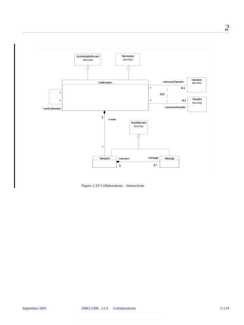
2
Figure 2-19 Collaborations - Interactions
{xor}
GeneralizableElement(from Core)
Namespace(from Core)
Message
Operation(from Core)
Interaction
1 1..*1
+message
1..*
Classifier(from Core)
Collaboration
* 0..1*
+representedOperation
0..1
1
*
+context1
+interaction
*
* 0..1*
+representedClassifier
0..1*
*
+usedCollaboration
*
*
ModelElement(from Core)
September 2001 OMG-UML , v1.4 Collaborations 2-119
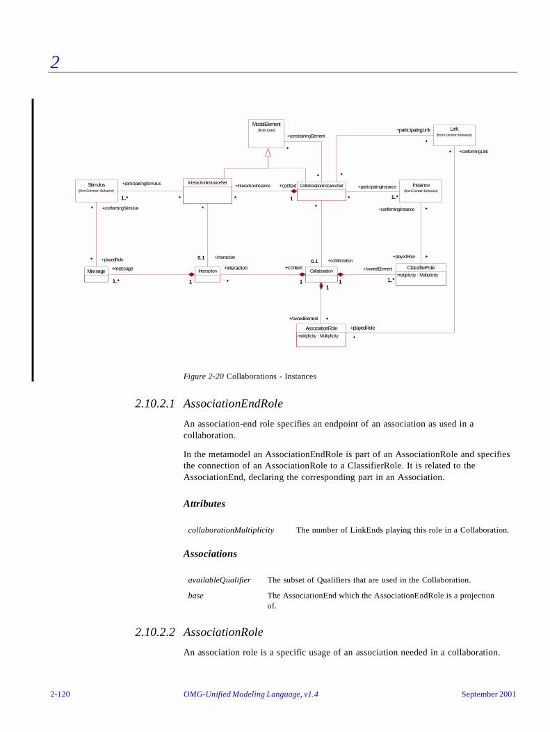
2
Figure 2-20 Collaborations - Instances
2.10.2.1 AssociationEndRole
An association-end role specifies an endpoint of an association as used in a collaboration.
In the metamodel an AssociationEndRole is part of an AssociationRole and specifies the connection of an AssociationRole to a ClassifierRole. It is related to the AssociationEnd, declaring the corresponding part in an Association.
Attributes
Associations
2.10.2.2 AssociationRole
An association role is a specific usage of an association needed in a collaboration.
collaborationMultiplicity The number of LinkEnds playing this role in a Collaboration.
availableQualifier The subset of Qualifiers that are used in the Collaboration.
base The AssociationEnd which the AssociationEndRole is a projection of.
Message
Stimulus(from Common Behavior)
*
*
+playedRole*
+conformingStimulus*
Interaction
1..* 1
+message
1..* 1
ClassifierRolemultiplicity : Multiplicity
AssociationRolemultiplicity : Multiplicity
InteractionInstanceSet
*1..* *
+participatingStimulus
1..*
0..1
*
+interaction0..1
*
Collaboration
* 1
+interaction
*
+context
1 1..*1
+/ownedElement
1..*1
*
1
+/ownedElement *
1
Instance(from Common Behavior)
*
*
+playedRole *
+conformingInstance *
ModelElement(from Core) Link
(from Common Behavior)
*
*
+playedRole
*
+conformingLink*
CollaborationInstanceSet
1*
+context
1
+interactionInstance
*
0..1
*
+collaboration0..1
*
* 1..**
+participatingInstance
1..*
*
*
+constrainingElement
*
*
*
*
+participatingLink
*
*
2-120 OMG-Unified Modeling Language, v1.4 September 2001

2
In the metamodel an AssociationRole specifies a restricted view of an Association used in a Collaboration. An AssociationRole is a composition of a set of AssociationEndRoles corresponding to the AssociationEnds of its base Association.
Attributes
Associations
2.10.2.3 ClassifierRole
A classifier role is a specific role played by a participant in a collaboration. It specifies a restricted view of a classifier, defined by what is required in the collaboration.
In the metamodel a ClassifierRole specifies one participant of a Collaboration; that is, a role Instances conform to. A ClassifierRole defines a set of Features, which is a subset of those available in the base Classifiers, as well as a subset of ModelElements contained in the base Classifiers, that are used in the role. The ClassifierRole may be connected to a set of AssociationRoles via AssociationEndRoles. As ClassifierRole is a kind of Classifier, a Generalization relationship may be defined between two ClassifierRoles. The child role is a specialization of the parent; that is, the Features and the contents of the child includes the Features and contents of the parent.
Attributes
Associations
2.10.2.4 Collaboration
A collaboration describes how an operation or a classifier, like a use case, is realized by a set of classifiers and associations used in a specific way. The collaboration defines a set of roles to be played by instances and links, as well as a set of interactions that define the communication between the instances when they play the roles.
multiplicity The number of Links playing this role in a Collaboration.
base The Association which the AssociationRole is a view of.
conformingLink The collection of Links that conforms to the AssociationRole.
multiplicity The number of Instances playing this role in a Collaboration.
availableContents The subset of ModelElements contained in the base Classifier, which is used in the Collaboration.
availableFeature The subset of Features of the base Classifier, which is used in the Collaboration.
base The Classifiers, which the ClassifierRole is a view of.
conformingInstance The collection of Instances that conforms to the ClassifierRole.
September 2001 OMG-UML , v1.4 Collaborations 2-121
2
In the metamodel a Collaboration contains a set of ClassifierRoles and AssociationRoles, which represent the Classifiers and Associations that take part in the realization of the associated Classifier or Operation. The Collaboration may also contain a set of Interactions that are used for describing the behavior performed by Instances conforming to the participating ClassifierRoles.
A Collaboration specifies a view (restriction, slice, projection) of a model of Classifiers. The projection describes the required relationships between Instances that conform to the participating ClassifierRoles, as well as the required subsets of the Features and contained ModelElements of these Classifiers. Several Collaborations may describe different projections of the same set of Classifiers. Hence, a Classifier can be a base for several ClassifierRoles.
A Collaboration may also reference a set of ModelElements, usually Classifiers and Generalizations, needed for expressing structural requirements, such as Generalizations required between the Classifiers themselves to fulfill the intent of the Collaboration.
A Collaboration is a GeneralizableElement, which implies that one Collaboration may specify a task that is a specialization of the task of another Collaboration.
Associations
2.10.2.5 CollaborationInstanceSet
A collaboration instance set references a set of instances that jointly collaborate in performing the particular task specified by the collaboration of the collaboration instance. The instances in the collaboration instance set play the roles defined in the collaboration.
In the metamodel a CollaborationInstanceSet references a set of Instances and Links that play the roles defined by the ClassifierRoles and AssociationRoles of the CollaborationInstanceSet’s Collaboration.
constrainingElement The ModelElements that add extra constraints, like Generalization and Constraint, on the ModelElements participating in the Collaboration.
interaction The set of Interactions that are defined within the Collaboration.
ownedElement (Inherited from Namespace) The set of roles defined by the Collaboration. These are ClassifierRoles and AssociationRoles.
representedClassifier The Classifier the Collaboration is a realization of. (Used if the Collaboration represents a Classifier.)
representedOperation The Operation the Collaboration is a realization of. (Used if the Collaboration represents an Operation.)
usedCollaboration Collaborations that are used when defining the source Collaboration.
2-122 OMG-Unified Modeling Language, v1.4 September 2001
2
A CollaborationInstanceSet contains an InteractionInstanceSet, which references the set of Stimuli that are interchanged between the Instances of the CollaborationInstanceSet and corresponds to the Messages of an Interaction in the CollaborationInstanceSet’s Collaboration.
Associations
2.10.2.6 Interaction
An interaction specifies the communication between instances performing a specific task. Each interaction is defined in the context of a collaboration.
In the metamodel an Interaction contains a set of Messages specifying the communication between a set of Instances conforming to the ClassifierRoles of the owning Collaboration.
Associations
2.10.2.7 InteractionInstanceSet
An interaction instance set is the set of stimuli that participate in a collaboration instance set.
In the metamodel an InteractionInstanceSet references a collection of Stimuli that conform to the Messages of the InteractionInstanceSet’s Interaction.
constrainingElement The ModelElements that add extra constraints, like Generalization and Constraint, on the ModelElements participating in the Collaboration.
collaboration The Collaboration, which declares the roles that the Instances that participate in the CollaborationInstanceSet play.
interactionInstanceSet The InteractionInstanceSet that references the Stimuli passed between the Instances when performing the task of the CollaborationInstanceSet’s Collaboration.
participatingInstance The set of Instances that participate in the CollaborationInstanceSet.
participatingLink The set of Links that participate in the CollaborationInstanceSet.
context The Collaboration that defines the context of the Interaction.
message The Messages that specify the communication in the Interaction.
September 2001 OMG-UML , v1.4 Collaborations 2-123
2
Associations
2.10.2.8 Message
A message defines a particular communication between instances that is specified in an interaction.
In the metamodel a Message defines one specific kind of communication in an Interaction. A communication can be raising a Signal, invoking an Operation, creating or destroying an Instance. The Message specifies not only the kind of communication, but also the roles of the sender and the receiver, the dispatching Action, and the role played by the communication Link. Furthermore, the Message defines the relative sequencing of Messages within the Interaction.
Associations
2.10.3 Well-Formedness Rules
The following well-formedness rules apply to the Collaborations package.
2.10.3.1 AssociationEndRole
[1] The type of the ClassifierRole must conform to the type of the base AssociationEnd.
context The CollaborationInstanceSet that defines the context of the InteractionInstanceSet.
participating-Stimulus
The Stimuli that participate in the performance of the CollaborationInstanceSet.
interaction The Interaction that defines the interaction pattern that the stimuli conforms to.
action The Action that causes a Stimulus to be sent according to the Message.
activator The Message that invokes the behavior causing the dispatching of the current Message.
communicationConnection The AssociationRole played by the Links used in the communications specified by the Message.
conformingStimulus The collection of Stimuli that conforms to the Message.
interaction The Interaction of which the Message is a part.
receiver The role of the Instance that receives the communication and reacts to it.
predecessor The set of Messages whose completion enables the execution of the current Message. All of them must be completed before execution begins.
sender The role of the Instance that invokes the communication and possibly receives a response.
2-124 OMG-Unified Modeling Language, v1.4 September 2001
2
self.type.base = self.base.type
or
self.type.base.allParents->includes (self.base.type)
[2] The type must be a kind of ClassifierRole.
self.type.oclIsKindOf (ClassifierRole)
[3] The qualifiers used in the AssociationEndRole must be a subset of those in the baseAssociationEnd.
self.base.qualifier->includesAll (self.availableQualifier)
[4] In a Collaboration an Association may only be used for traversal if it is allowed by thebase Association.
self.isNavigable implies self.base.isNavigable
[5] An AssociationEndRole is not a role of another AssociationEndRole.
not self.base.oclIsKindOf (AssociationEndRole)
2.10.3.2 AssociationRole
[1] The AssociationEndRoles must conform to the AssociationEnds of the base Association.
Sequence{ 1..(self.connection->size) }->forAll (index |
self.connection->at(index).base =
self.base.connection->at(index))
[2] The endpoints must be a kind of AssociationEndRoles.
self.connection->forAll( r | r.oclIsKindOf (AssociationEndRole) )
[3] An AssociationEnd is not a role of another AssociationEnd.
not self.base.oclIsKindOf (AssociationEnd)
2.10.3.3 ClassifierRole
[1] The AssociationRoles connected to the ClassifierRole must match a subset of theAssociations connected to the base Classifiers.
self.allAssociations->forAll( ar |
self.base.allAssociations->exists ( a | ar.base = a ) )
[2] The Features and contents of the ClassifierRole must be subsets of those of the baseClassifiers.
self.base.allFeatures->includesAll (self.allAvailableFeatures)
and
self.base.allContents->includesAll (self.allAvailableContents)
[3] A ClassifierRole does not have any Features of its own.
self.allFeatures->isEmpty
[4] A ClassifierRole is not a role of another ClassifierRole.
September 2001 OMG-UML , v1.4 Collaborations 2-125
2
not self.base.oclIsKindOf (ClassifierRole)
Additional operations
[1] The operation allAvailableFeatures results in the set of all Features contained in theClassifierRole together with those contained in the parents.
allAvailableFeatures : Set(Feature);
allAvailableFeatures = self.availableFeature->union
(self.parent.allAvailableFeatures)
[2] The operation allAvailableContents results in the set of all ModelElements contained inthe ClassifierRole together with those contained in the parents.
allAvailableContents : Set(ModelElement);
allAvailableContents = self.availableContents->union
(self.parent.allAvailableContents)
2.10.3.4 Collaboration
[1] All Classifiers and Associations of the ClassifierRoles and AssociationRoles in theCollaboration must be included in the namespace owning the Collaboration.
self.allContents->forAll ( e |
(e.oclIsKindOf (ClassifierRole) implies
self.namespace.allContents->includes (
e.oclAsType(ClassifierRole).base) )
and
(e.oclIsKindOf (AssociationRole) implies
self.namespace.allContents->includes (
e.oclAsType(AssociationRole).base) ))
[2] All the constraining ModelElements must be included in the namespace owning theCollaboration.
self.constrainingElement->forAll ( ce |
self.namespace.allContents->includes (ce) )
[3] If a ClassifierRole or an AssociationRole does not have a name, then it should be the onlyone with a particular base.
self.allContents->forAll ( p |
(p.oclIsKindOf (ClassifierRole) implies
p.name = '' implies
self.allContents->forAll ( q |
q.oclIsKindOf(ClassifierRole) implies
(p.oclAsType(ClassifierRole).base =
q.oclAsType(ClassifierRole).base implies
p = q) ) )
and
2-126 OMG-Unified Modeling Language, v1.4 September 2001
2
(p.oclIsKindOf (AssociationRole) implies
p.name = '' implies
self.allContents->forAll ( q |
q.oclIsKindOf(AssociationRole) implies
(p.oclAsType(AssociationRole).base =
q.oclAsType(AssociationRole).base implies
p = q) ) )
)
[4] A Collaboration may only contain ClassifierRoles and AssociationRoles, theGeneralizations and the Constraints between them, and Actions used in theCollaboration’s Interactions.
self.allContents->forAll ( p |
p.oclIsKindOf (ClassifierRole) or
p.oclIsKindOf (AssociationRole) or
p.oclIsKindOf (Generalization) or
p.oclIsKindOf (Action) or
p.oclIsKindOf (Constraint) )
[5] An Action contained in a Collaboration must be connected to a Message; that is, be thedispatching Action of the Message, in an Interaction of the Collaboration.
self.allContents->forAll ( p |
p.oclIsKindOf (Action) implies
self.interaction->exists ( i : Interaction |
i.messages->exists ( m : Message | m.action = p ) ) )
[6] A role with the same name as one of the roles in a parent of the Collaboration must be achild (a specialization) of that role.
self.contents->forAll ( c |
self.parent.allContents->forall ( p |
c.name = p.name implies c.allParents->include (p) ))
Additional operations
[1] The operation allContents results in the set of all ModelElements contained in theCollaboration together with those contained in the parents except those that have beenspecialized.
allContents : Set(ModelElement);
allContents = self.contents->union (
self.parent.allContents->reject ( e |
self.contents.name->include (e.name) ))
2.10.3.5 CollaborationInstanceSet
[1] The Interaction of the CollaborationInstanceSet’s InteractionInstanceSet must be definedwithin the CollaborationInstanceSet’s Collaboration.
September 2001 OMG-UML , v1.4 Collaborations 2-127
2
self.collaboration.interaction->includes (
self.interactionInstanceSet.interaction)
2.10.3.6 Interaction
[1] All Signals being sent must be included in the namespace owning the Collaboration inwhich the Interaction is defined.
self.message->forAll ( m |
m.action.oclIsKindOf(SendAction) implies
self.context.namespace.allContents->includes (
m.action->oclAsType (SendAction).signal) )
2.10.3.7 InteractionInstanceSet
No extra well-formedness rules.
2.10.3.8 Message
[1] The sender and the receiver must participate in the Collaboration, which defines thecontext of the Interaction.
self.interaction.context.ownedElement->includes (self.sender)
and
self.interaction.context.ownedElement->includes (self.receiver)
[2] The predecessors and the activator must be contained in the same Interaction.
self.predecessor->forAll ( p | p.interaction = self.interaction )
and
self.activator->forAll ( a | a.interaction = self.interaction )
[3] The predecessors must have the same activator as the Message.
self.allPredecessors->forAll ( p | p.activator = self.activator )
[4] A Message cannot be the predecessor of itself.
not self.allPredecessors->includes (self)
[5] The communicationLink of the Message must be an AssociationRole in the context of theMessage’s Interaction.
self.interaction.context.ownedElement->includes (
self.communicationConnection)
[6] The sender and the receiver roles must be connected by the AssociationRole, which acts asthe communication connection.
self.communicationConnection->size > 0 implies
self.communicationConnection.connection->exists (ar |
ar.type = self.sender)
and
2-128 OMG-Unified Modeling Language, v1.4 September 2001
2
self.communicationConnection.connection->exists (ar |
ar.type = self.receiver)
Additional operations
[1] The operation allPredecessors results in the set of all Messages that precede the currentone.
allPredecessors : Set(Message);
allPredecessors = self.predecessor->union
(self.predecessor.allPredecessors)
2.10.4 Detailed Semantics
This section provides a description of the semantics of the elements in the Collaborations package. It is divided into two parts: Collaboration and Interaction. The description of behavior involves two aspects: 1) the structural description of the participants, and 2) the description of their communication patterns. The structure of Instances playing roles in a behavior and their relationships is described by a collaboration. The communication pattern performed by Instances playing the roles to accomplish a specific purpose is specified by an interaction.
2.10.4.1 Collaboration
Behavior is implemented by ensembles of instances that exchange stimuli to accomplish a task. To understand the mechanisms used in a design, it is important to see only those instances and their interactions that are involved in accomplishing the task or a related set of tasks, projected from the larger system of which they are parts of, and might be used for other purposes as well. Such a static construct is called a collaboration.
A collaboration defines an ensemble of participants that are needed for a given set of purposes. The participants define roles that instances and links play when interacting with each other. The roles to be played by the instances are modeled as classifier roles, and by the links as association roles. Classifier roles and association roles define a usage of instances and links, while the classifiers and associations specify all required properties of these instances and links. This means that the structure of an ensemble of interlinked instances conforms to the roles in a collaboration as they collaborate to achieve a given task. Reasoning about the behavior of an ensemble of instances can therefore be done in the context of the collaboration as well as in the context of the instances.
A collaboration can be used for specification of how an operation or a classifier, like a use case, is realized by an ensemble of classifiers and associations. Together, the classifiers and their associations participating in the collaboration meet the requirements of the realized operation or classifier. The collaboration defines a context in which the behavior of the realized element can be specified.
September 2001 OMG-UML , v1.4 Collaborations 2-129

2
A collaboration specifies what properties instances must have to be able to take part in the collaboration; that is, a role in the collaboration specifies the required set of features a conforming instance must have. Furthermore, the collaboration also states what associations must exist between the participants, as well as what classifiers a participant, like a subsystem, must contain. Neither all features nor all contents of the participating classifiers and not all associations between these classifiers are always required in a particular collaboration. Because of this, a collaboration is defined in terms of classifier roles. A classifier role is a description of the features required in a particular collaboration; that is, a classifier role can be seen as a projection of a classifier, which is called the base of the classifier role. (In fact, since an instance can originate from multiple classifiers at the same time (multiple classification), a classifier role can have several base classifiers.) However, instances of different classifiers can play the role defined by the classifier role, as long as they have all the required properties. Several classifier roles may have the same base classifier, even in the same collaboration, but their features and contained elements may be different subsets of the features and contained elements of the classifier. These classifier roles specify different roles played by (possibly different) instances of the same classifier.
A collaboration may be attached to an operation or a classifier, like a use case, to describe the context in which their behavior occurs; that is, what roles instances play to perform the behavior specified by the operation or the use case. A collaboration used in this way describes the realization of the operation or the classifier. A collaboration that describes for example a use case, references classifiers and associations in general, while a collaboration describing an operation includes only the parameters and the local variables of the operation, as well as ordinary associations attached to the classifier owning the operation. The interactions defined within the collaboration (see below) specify the communication pattern between the instances when they perform the behavior specified in the operation or the use case. A collaboration may also be attached to a class to define its static structure; that is, how its attributes, parameters etc. cooperate with each other.
In a collaboration the association roles define what associations are needed between the classifiers in this context. Each association role represents the usage of an association in the collaboration, and it is defined between the classifier roles that represent the associated classifiers. The represented association is called the base association of the association role. As the association roles specify a particular usage of an association in a specific collaboration, all constraints expressed by the association ends are not necessarily required to be fulfilled in the specified usage. The multiplicity of the association end may be reduced in the collaboration; that is, the upper and the lower bounds of the association end roles may be inside the bounds of the corresponding end of the base association, as it might be that only a subset of the associated instances participate in the collaboration instance set. Similarly, an association may be traversed in some, but perhaps not all, of the allowed directions in the specific collaboration; that is, the value of the isNavigable property of an association end role may be false even if the value of that property of the base association end is true. (However, the opposite is not true; that is, an association may not be used for traversal in a direction that is not allowed according to the isNavigable properties of the association ends.) The changeability and ordering of an association end may be strengthened in an association end role; that is, in a particular usage the end is used in a more restricted way than is defined by the association. Furthermore, if
2-130 OMG-Unified Modeling Language, v1.4 September 2001
2
an association has a collection of qualifiers (see the Core), some of them may be used in a specific collaboration. An association end role may therefore include a subset of the qualifiers defined by the corresponding association end of the base association.
A collaboration instance set references a collection of instances that play the roles defined in the collaboration instance set’s collaboration. An instance participating in a collaboration instance set plays a specific role; that is, conforms to a classifier role, in the collaboration. The number of instances that should play one specific role in a collaboration is specified by the classifier role’s multiplicity. Different instances may play the same role but in different collaboration instance sets. Since all these instances play the same role, they must all conform to the classifier role specifying the role. Thus, they are normally instances of one of the base classifier of the classifier role, or one of their descendants. The only requirement on conforming instances is that they must offer operations according to the classifier role, as well as support attribute links corresponding to the attributes specified by the classifier role, and links corresponding to the association roles connected to the classifier role. They may, therefore, be instances of any classifier meeting this requirement. The instances may, of course, have more attribute links than required by the classifier role, which for example would be the case if they originate from a classifier being a child of a base classifier. Moreover, a conforming instance may also support more attribute links than required if it originates from multiple classifiers (multiple classification). Finally, one instance may play different roles in different collaboration instance sets of the same collaboration. In fact, the instance may play multiple roles in the same collaboration instance set.
Collaborations (but not collaboration instance sets) may have generalization relationships to other collaborations. This means that one collaboration can specify a specialization of another collaboration’s task. This implies that all the roles of the parent collaboration are also available in the child collaboration; the child collaboration may, of course, also contain new roles. The former roles may possibly be specialized with new features; that is, the role defined in the parent is replaced in the child by a role with the same name as the parent role. The role in the child must reference the same collection of features and the same collection of contained elements as the role in the parent, and may also reference some additional features and additional contained elements. In this way it is possible to specialize a collaboration both by adding new roles and by replacing existing roles with specializations of them. The specialized role, that is, a role with a generalization relationship to the replaced role, may both reference new features and replace (override) features of its parent. Note that the base classifiers of the specialized roles are not necessarily specializations of the base classifiers of the parent’s roles; it is enough that they contain all the required features.
How the instances referenced by a collaboration instance set should interact to jointly perform the behavior of the classifier realized by the collaboration is specified with a set of interactions (see below). The collaboration thus specifies the context in which these interactions are performed. If the collaboration represents an operation, the context includes things like parameters, attributes, and classifiers contained in the classifier owning the operation. The interactions then specify how the arguments, the attribute values, the instances etc. will cooperate to perform the behavior specified by the operation. If the collaboration is a specialization of another collaboration, all communications specified by the parent collaboration are also included in the child, as
September 2001 OMG-UML , v1.4 Collaborations 2-131
2
the child collaboration includes all the roles of the parent. However, new messages may be inserted into these sequences of communication, since the child may include specializations of the parent’s roles as well as new roles. The child may of course also include completely new interactions that do not exist in the parent.
Two or more collaborations may be composed to form a new collaboration. For example, when refining a superordinate use case into a set of subordinate use cases, the collaborations specifying each of the subordinate use cases may be composed into one collaboration, which will be a (simple) refinement of the superordinate collaboration. The composition is done by observing that at least one instance must participate in both sets of collaborating instances. This instance has to conform to one classifier role in each collaboration. In the composite collaboration these two classifier roles are merged into a new one, which will contain all features included in either of the two original classifier roles. The new classifier role will, of course, be able to fulfill the requirements of both of the previous collaborations, so the instance participating in both of the two sets of collaborating instances will conform to the new classifier role.
A parameterized collaboration represents a design construct that can be used repeatedly in different designs. The participants in the collaboration, including the classifiers and relationships, can be parameters of the generic collaboration. The parameters are bound to particular model elements in each instantiation of generic collaboration. Such a parameterized collaboration can capture the structure of a design pattern (note that a design pattern involves more than structural aspects). Whereas most collaborations can be anonymous because they are attached to a named model element, collaboration patterns are free standing design constructs that must have names.
A collaboration may be a specification of a template. There will not be any instances of such a collaboration template, but it can be used for generating ordinary collaborations, which may be instantiated. Collaboration templates may have parameters that act like placeholders in the template. Usually, these parameters would be used as base classifiers and associations, but other kinds of model elements can also be defined as parameters in the collaboration, like operation or signal. In a collaboration generated from the template these parameters are refined by other model elements that make the collaboration instantiable.
Moreover, a collaboration may also contain a set of constraining model elements, like constraints and generalizations perhaps together with some extra classifiers. These constraining model elements do not participate in the collaboration themselves, but are used for expressing the extra constraints on the participating elements in the collaboration that cannot be covered by the participating roles themselves. For example, in a collaboration template it might be required that the base classifiers of two roles must have a common ancestor, or one role must be a subclass of another one. These kinds of requirements cannot be expressed with association roles, as the association roles express the required links between participating instances. An extra set of model elements may therefore be included in the collaboration.
2-132 OMG-Unified Modeling Language, v1.4 September 2001
2
2.10.4.2 Interaction
An interaction is defined in the context of a collaboration. It specifies the communication patterns between its roles. More precisely, it contains a set of partially ordered messages, each specifying one communication, such as what signal to be sent or what operation to be invoked, as well as the roles to be played by the sender and the receiver, respectively.
The purpose of an interaction is to specify the communication between an ensemble of interacting instances performing a specific task. An interaction is defined within a collaboration; that is, the collaboration defines the context in which the interaction takes place. The instances performing the communication specified by the interaction are included in a collaboration instance set; that is, they conform to the classifier roles of the collaboration instance set’s collaboration.
An interaction specifies the sending of a set of stimuli. These are partially ordered based on which execution thread they belong to. Within each thread the stimuli are sent in a sequential order while stimuli of different threads may be sent in parallel or in an arbitrary order.
An interaction instance set references the collection of stimuli that constitute the actual communication between the collection of instances. These instances are the collection of instances that participate in the collaboration instance set owning the interaction instance set. Hence, the interaction instance set includes those stimuli that the instances communicate when performing the task of the collaboration instance set. The stimuli of an interaction instance set match the messages of the interaction instance set’s interaction.
A message is a specification of a communication. It specifies the roles of the sender and the receiver instances, as well as which association role specifies the communication link. The message is connected to an action, which specifies the statement that, when executed, causes the communication specified by the message to take place. If the action is a call action or a send action, the signal to be sent or the operation to be invoked in the communication is stated by the action. The action also contains the argument expressions that, when executed, will determine the actual arguments being transmitted in the communication. Moreover, any conditions or iterations of the communication are also specified by the action. Apart from send action and call action, the action connected to a message can also be of other kinds, like create action and destroy action. In these cases, the communication will not raise a signal or invoke an operation, but cause a new instance to be created or an already existing instance to be destroyed. In the case of a create action, the receiver specified by the message is the role to be played by the instance, which is created when the action is performed.
The stimuli being sent when an action is executed conforms to a message, implying that the sender and receiver instances of the stimuli are in conformance with the sender and the receiver roles specified by the message. Furthermore, the action dispatching the stimulus is the same as the action attached to the message. If the action connected to the message is a create action or destroy action, the receiver role of the message specifies the role to be played by the instance, or was played by the instance, respectively.
September 2001 OMG-UML , v1.4 Collaborations 2-133
2
The interaction specifies the activator and predecessors of each message. The activator is the message that invoked the procedure that in turn invokes the current message. Every message except the initial messages of an interaction thus has an activator. The predecessors are the set of messages that must be completed before the current message may be executed. The first message in a procedure of course has no predecessors. If a message has more than one predecessor, it represents the joining of two threads of control. If a message has more than one successor (the inverse of predecessor), it indicates a fork of control into multiple threads. Thus, the predecessor’s relationship imposes a partial ordering on the messages within a procedure, whereas the activator relationship imposes a tree on the activation of operations. Messages may be executed concurrently subject to the sequential constraints imposed by the predecessors and activator relationship.
2.10.5 Notes
In UML, the term Pattern is a synonym for a collaboration template that describes the structure of a design pattern. This definition is not as powerful as the term is used in other contexts. In general, design patterns involve many nonstructural aspects, such as heuristics for their use and lists of advantages and disadvantages. Such aspects are not modeled by UML and may be represented as text or tables.
2.11 Use Cases
2.11.1 Overview
The Use Cases package is a subpackage of the Behavioral Elements package. It specifies the concepts used for definition of the functionality of an entity like a system. The package uses constructs defined in the Foundation package of UML as well as in the Common Behavior package.
The elements in the Use Cases package are primarily used to define the behavior of an entity, like a system or a subsystem, without specifying its internal structure. The key elements in this package are UseCase and Actor. Instances of use cases and instances of actors interact when the services of the entity are used. How a use case is realized in terms of cooperating objects, defined by classes inside the entity, can be specified with a Collaboration. A use case of an entity may be refined to a set of use cases of the elements contained in the entity. How these subordinate use cases interact can also be expressed in a Collaboration. The specification of the functionality of the system itself is usually expressed in a separate use-case model; that is, a Model stereotyped «useCaseModel» (see Section 4.3, “Stereotypes and Notation,” on page 4-2). The use cases and actors in the use-case model are equivalent to those of the top-level package.
The following sections describe the abstract syntax, well-formedness rules, and semantics of the Use Cases package.
2-134 OMG-Unified Modeling Language, v1.4 September 2001
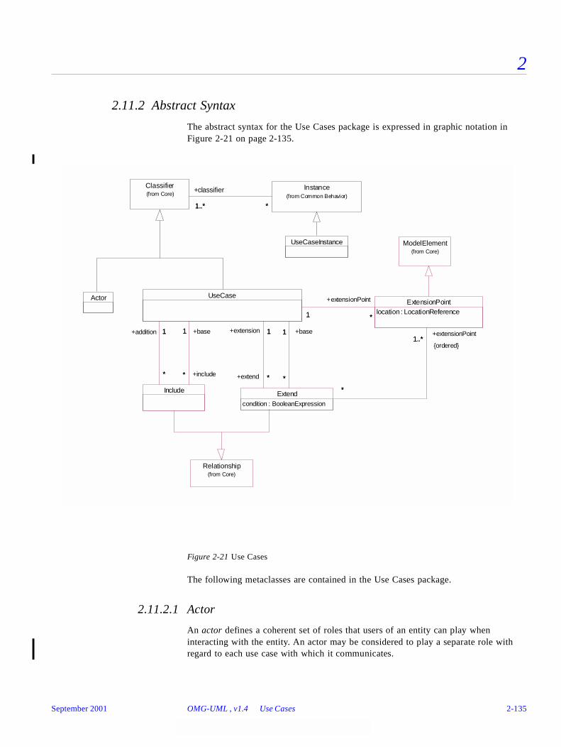
2
2.11.2 Abstract Syntax
The abstract syntax for the Use Cases package is expressed in graphic notation in Figure 2-21 on page 2-135.
Figure 2-21 Use Cases
The following metaclasses are contained in the Use Cases package.
2.11.2.1 Actor
An actor defines a coherent set of roles that users of an entity can play when interacting with the entity. An actor may be considered to play a separate role with regard to each use case with which it communicates.
UseCaseInstance
Actor
Classifier(from Core)
Instance(from Common Behavior)
1..* *
+classifier
1..* *
ModelElement(from Core)
Include
UseCase
*
1
+include*
+addition 1
*
1
*
+base1
ExtensionPointlocation : LocationReference
*1
+extensionPoint
*1
Extendcondition : BooleanExpression
1
*
+base1
*
1
*
+extension 1
+extend *
1..*
*
+extensionPoint1..*
{ordered}
*
Relationship(from Core)
September 2001 OMG-UML , v1.4 Use Cases 2-135
2
In the metamodel Actor is a subclass of Classifier. An Actor has a Name and may communicate with a set of UseCases, and, at realization level, with Classifiers taking part in the realization of these UseCases. An Actor may also have a set of Interfaces, each describing how other elements may communicate with the Actor.
An Actor may have generalization relationships to other Actors. This means that the child Actor will be able to play the same roles as the parent Actor, that is, communicate with the same set of UseCases, as the parent Actor.
2.11.2.2 Extend
An extend relationship defines that instances of a use case may be augmented with some additional behavior defined in an extending use case.
In the metamodel an Extend relationship is a directed relationship implying that a UseCaseInstance of the base UseCase may be augmented with the structure and behavior defined in the extending UseCase. The relationship consists of a condition, which must be fulfilled if the extension is to take place, and a sequence of references to extension points in the base UseCase where the additional behavior fragments are to be inserted.
Attributes
Associations
2.11.2.3 ExtensionPoint
An extension point references one or a collection of locations in a use case where the use case may be extended.
In the metamodel an ExtensionPoint has a name and one or a collection of descriptions of locations in the behavior of the owning use case, where a piece of behavior may be inserted into the owning use case.
Attributes
condition An expression specifying the condition that must be fulfilled if the extension is to take place.
base The UseCase to be extended.
extension The UseCase specifying the extending behavior.
extensionPoint A sequence of extension-points in the base UseCase specifying where the additions are to be inserted.
location A reference to one location or a collection of locations where an extension to the behavior of the use case may be inserted.
2-136 OMG-Unified Modeling Language, v1.4 September 2001
2
2.11.2.4 Include
An include relationship defines that a use case contains the behavior defined in another use case.
In the metamodel an Include relationship is a directed relationship between two UseCases implying that the behavior in the addition UseCase is inserted into the behavior of the base UseCase. The base UseCase may only depend on the result of performing the behavior defined in the addition UseCase, but not on the structure; that is, on the existence of specific attributes and operations, of the addition UseCase.
2.11.2.5 Associations
2.11.2.6 UseCase
The use case construct is used to define the behavior of a system or other semantic entity without revealing the entity’s internal structure. Each use case specifies a sequence of actions, including variants, that the entity can perform, interacting with actors of the entity.
In the metamodel UseCase is a subclass of Classifier, specifying the sequences of actions performed by an instance of the UseCase. The actions include changes of the state and communications with the environment of the UseCase. The sequences can be described using many different techniques, like Operation and Methods, ActivityGraphs, and StateMachines.
There may be Associations between UseCases and the Actors of the UseCases. Such an Association states that an instance of the UseCase and a user playing one of the roles of the Actor communicate. UseCases may be related to other UseCases by Extend, Include, and Generalization relationships. An Include relationship means that a UseCase includes the behavior described in another UseCase, while an Extend relationship implies that a UseCase may extend the behavior described in another UseCase, ruled by a condition. Generalization between UseCases means that the child is a more specific form of the parent. The child inherits all Features and Associations of the parent, and may add new Features and Associations.
The realization of a UseCase may be specified by a set of Collaborations; that is, the Collaborations define how Instances in the system interact to perform the sequences of the UseCase.
addition The UseCase specifying the additional behavior.
base The UseCase that is to include the addition.
September 2001 OMG-UML , v1.4 Use Cases 2-137
2
Associations
2.11.2.7 UseCaseInstance
A use case instance is the performance of a sequence of actions specified in a use case.
In the metamodel UseCaseInstance is a subclass of Instance. Each method performed by a UseCaseInstance is performed as an atomic transaction; that is, it is not interrupted by any other UseCaseInstance.
An explicitly described UseCaseInstance is called a scenario.
2.11.3 Well-FormednessRules
The following well-formedness rules apply to the Use Cases package.
2.11.3.1 Actor
[1] Actors can only have Associations to UseCases, Subsystems, and Classes and theseAssociations are binary.
self.associations->forAll(a |
a.connection->size = 2 and
a.allConnections->exists(r | r.type.oclIsKindOf(Actor)) and
a.allConnections->exists(r |
r.type.oclIsKindOf(UseCase) or
r.type.oclIsKindOf(Subsystem) or
r.type.oclIsKindOf(Class)))
[2] Actors cannot contain any Classifiers.
self.contents->isEmpty
2.11.3.2 Extend
[1] The referenced ExtensionPoints must be included in set of ExtensionPoint in the targetUseCase.
self.base.allExtensionPoints -> includesAll (self.extensionPoint)
extend A collection of Extend relationships to UseCases that the UseCase extends.
extensionPoint Defines a collection of ExtensionPoints where the UseCase may be extended.
include A collection of Include relationships to UseCases that the UseCase includes.
2-138 OMG-Unified Modeling Language, v1.4 September 2001
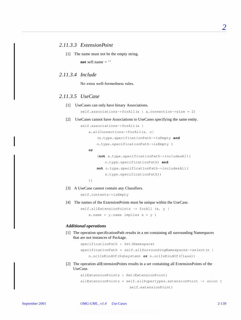
2
2.11.3.3 ExtensionPoint
[1] The name must not be the empty string.
not self.name = ‘’
2.11.3.4 Include
No extra well-formedness rules.
2.11.3.5 UseCase
[1] UseCases can only have binary Associations.
self.associations->forAll(a | a.connection->size = 2)
[2] UseCases cannot have Associations to UseCases specifying the same entity.
self.associations->forAll(a |
a.allConnections->forAll(s, o|
(s.type.specificationPath->isEmpty and
o.type.specificationPath->isEmpty )
or
(not s.type.specificationPath->includesAll(
o.type.specificationPath) and
not o.type.specificationPath->includesAll(
s.type.specificationPath))
))
[3] A UseCase cannot contain any Classifiers.
self.contents->isEmpty
[4] The names of the ExtensionPoints must be unique within the UseCase.
self.allExtensionPoints -> forAll (x, y |
x.name = y.name implies x = y )
Additional operations
[1] The operation specificationPath results in a set containing all surrounding Namespacesthat are not instances of Package.
specificationPath : Set(Namespace)
specificationPath = self.allSurroundingNamespaces->select(n |
n.oclIsKindOf(Subsystem) or n.oclIsKindOf(Class))
[2] The operation allExtensionPoints results in a set containing all ExtensionPoints of theUseCase.
allExtensionPoints : Set(ExtensionPoint)
allExtensionPoints = self.allSupertypes.extensionPoint -> union (
self.extensionPoint)
September 2001 OMG-UML , v1.4 Use Cases 2-139
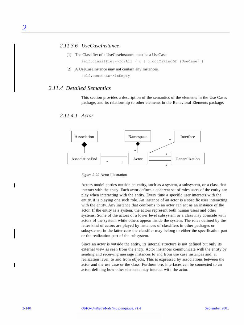
2
2.11.3.6 UseCaseInstance
[1] The Classifier of a UseCaseInstance must be a UseCase.
self.classifier->forAll ( c | c.oclIsKindOf (UseCase) )
[2] A UseCaseInstance may not contain any Instances.
self.contents->isEmpty
2.11.4 Detailed Semantics
This section provides a description of the semantics of the elements in the Use Cases package, and its relationship to other elements in the Behavioral Elements package.
2.11.4.1 Actor
Figure 2-22 Actor Illustration
Actors model parties outside an entity, such as a system, a subsystem, or a class that interact with the entity. Each actor defines a coherent set of roles users of the entity can play when interacting with the entity. Every time a specific user interacts with the entity, it is playing one such role. An instance of an actor is a specific user interacting with the entity. Any instance that conforms to an actor can act as an instance of the actor. If the entity is a system, the actors represent both human users and other systems. Some of the actors of a lower level subsystem or a class may coincide with actors of the system, while others appear inside the system. The roles defined by the latter kind of actors are played by instances of classifiers in other packages or subsystems; in the latter case the classifier may belong to either the specification part or the realization part of the subsystem.
Since an actor is outside the entity, its internal structure is not defined but only its external view as seen from the entity. Actor instances communicate with the entity by sending and receiving message instances to and from use case instances and, at realization level, to and from objects. This is expressed by associations between the actor and the use case or the class. Furthermore, interfaces can be connected to an actor, defining how other elements may interact with the actor.
Interface
Generalization
Association
AssociationEnd
Namespace
Actor* 1
*
*
*
*
2-140 OMG-Unified Modeling Language, v1.4 September 2001
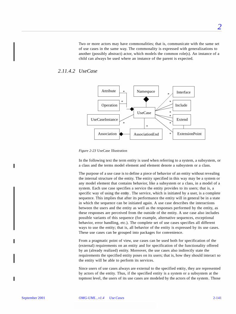
2
Two or more actors may have commonalities; that is, communicate with the same set of use cases in the same way. The commonality is expressed with generalizations to another (possibly abstract) actor, which models the common role(s). An instance of a child can always be used where an instance of the parent is expected.
2.11.4.2 UseCase
Figure 2-23 UseCase Illustration
In the following text the term entity is used when referring to a system, a subsystem, or a class and the terms model element and element denote a subsystem or a class.
The purpose of a use case is to define a piece of behavior of an entity without revealing the internal structure of the entity. The entity specified in this way may be a system or any model element that contains behavior, like a subsystem or a class, in a model of a system. Each use case specifies a service the entity provides to its users; that is, a specific way of using the entity . The service, which is initiated by a user, is a complete sequence. This implies that after its performance the entity will in general be in a state in which the sequence can be initiated again. A use case describes the interactions between the users and the entity as well as the responses performed by the entity, as these responses are perceived from the outside of the entity. A use case also includes possible variants of this sequence (for example, alternative sequences, exceptional behavior, error handling, etc.). The complete set of use cases specifies all different ways to use the entity; that is, all behavior of the entity is expressed by its use cases. These use cases can be grouped into packages for convenience.
From a pragmatic point of view, use cases can be used both for specification of the (external) requirements on an entity and for specification of the functionality offered by an (already realized) entity. Moreover, the use cases also indirectly state the requirements the specified entity poses on its users; that is, how they should interact so the entity will be able to perform its services.
Since users of use cases always are external to the specified entity, they are represented by actors of the entity. Thus, if the specified entity is a system or a subsystem at the topmost level, the users of its use cases are modeled by the actors of the system. Those
UseCase
Attribute
Operation
UseCaseInstance
AssociationEndAssociation
Namespace Interface
Include
Extend
ExtensionPoint
*
*
**
*
*
**
*
*
September 2001 OMG-UML , v1.4 Use Cases 2-141
2
actors of a lower level subsystem or a class that are internal to the system are often not explicitly defined. Instead, the use cases relate directly to model elements conforming to these implicit actors; that is, whose instances play the roles of these actors in interaction with the use cases. These model elements are contained in other packages or subsystems, where in the subsystem case they may be contained in the specification part or the realization part. The distinction between actor and conforming element like this is often neglected; thus, they are both referred to by the term actor.
There may be associations between use cases and actors, meaning that the instances of the use case and the actor communicate with each other. One actor may communicate with several use cases of an entity; that is, the actor may request several services of the entity, and one use case communicates with one or several actors when providing its service. Note that two use cases specifying the same entity cannot communicate with each other since each of them individually describes a complete usage of the entity. Moreover, use cases always use signals when communicating with actors outside the system, while they may use other communication semantics when communicating with elements inside the system.
The interaction between actors and use cases can be defined with interfaces. An interface of a use case defines a subset of the entire interaction defined in the use case. Different interfaces offered by the same use case need not be disjoint.
A use case can be described in plain text, using operations and methods together with attributes, in activity graphs, by a state machine, or by other behavior description techniques, such as preconditions and postconditions. The interaction between a use case and its actors can also be presented in collaboration diagrams for specification of the interactions between the entity containing the use case and the entity’s environment.
A use-case instance is a performance of a use case, initiated by a message instance from an instance of an actor. As a response the use-case instance performs a sequence of actions as specified by the use case, like communicating with actor instances, not necessarily only the initiating one. The actor instances may send new message instances to the use-case instance and the interaction continues until the instance has responded to all input and does not expect any more input, when it ends. Each method performed by a use-case instance is performed as an atomic transaction; that is, it is not interrupted by any other use-case instance.
In the case where subsystems are used to model the system’s containment hierarchy, the system can be specified with use cases at all levels, as use cases can be used to specify subsystems and classes. A use case specifying one model element is then refined into a set of smaller use cases, each specifying a service of a model element contained in the first one. The use case of the whole may be referred to as superordinate to its refining use cases, which, correspondingly, may be called subordinate in relation to the first one. The functionality specified by each superordinate use case is completely traceable to its subordinate use cases. Note, though, that the structure of the container element is not revealed by the use cases, since they only specify the functionality offered by the element. The subordinate use cases of a specific superordinate use case cooperate to perform the superordinate one. Their cooperation is specified by collaborations and may be presented in collaboration diagrams. A specific subordinate use case may appear in several collaborations; that is
2-142 OMG-Unified Modeling Language, v1.4 September 2001
2
play a role in the performances of several superordinate use cases. In each such collaboration, other roles specify the cooperation with this specific subordinate use case. These roles are the roles played by the actors of that subordinate use case. Some of these actors may be the actors of the superordinate use case, as each actor of a superordinate use case appears as an actor of at least one of the subordinate use cases. Furthermore, the interfaces of a superordinate use case are traceable to the interfaces of those subordinate use cases that communicate with actors that are also actors of the superordinate use case.
The environment of subordinate use cases is the model element containing the model elements specified by these use cases. Thus, from a bottom-up perspective, an interaction between subordinate use cases results in a superordinate use case , that is, a use case of the container element.
Use cases of classes are mapped onto operations of the classes, since a service of a class in essence is the invocation of the operations of the class. Some use cases may consist of the application of only one operation, while others may involve a set of operations, usually in a well-defined sequence. One operation may be needed in several of the services of the class, and will therefore appear in several use cases of the class.
The realization of a use case depends on the kind of model element it specifies. For example, since the use cases of a class are specified by means of operations of the class, they are realized by the corresponding methods, while the use cases of a subsystem are realized by the elements contained in the subsystem. Since a subsystem does not have any behavior of its own, all services offered by a subsystem must be a composition of services offered by elements contained in the subsystem (i.e., eventually by classes). These elements will collaborate and jointly perform the behavior of the specified use case. One or a set of collaborations describes how the realization of a use case is made. Hence, collaborations are used for specification of both the refinement and the realization of a use case in terms of subordinate use cases.
The usage of use cases at all levels imply not only a uniform way of specification of functionality at all levels, but also a powerful technique for tracing requirements at the system package level down to operations of the classes. The propagation of the effect of modifying a single operation at the class level all the way up to the behavior of the system package is managed in the same way.
Commonalities between use cases can be expressed in three different ways: with generalization, include, and extend relationships. A generalization relationship between use cases implies that the child use case contains all the attributes, sequences of behavior, and extension points defined in the parent use case, and participates in all relationships of the parent use case. The child use case may also define new behavior sequences, as well as add additional behavior into and specialize existing behavior of the inherited ones. One use case may have several parent use cases and one use case may be a parent to several other use cases.
An include relationship between two use cases means that the behavior defined in the target use case is included at one location in the sequence of behavior performed by an instance of the base use case. When a use-case instance reaches the location where the behavior of an another use case is to be included, it performs all the behavior described by the included use case and then continues according to its original use case. This
September 2001 OMG-UML , v1.4 Use Cases 2-143

2
means that although there may be several paths through the included use case due to (e.g., conditional statements), all of them must end in such a way that the use-case instance can continue according to the original use case. One use case may be included in several other use cases and one use case may include several other use cases. The included use case may not be dependent on the base use case. In that sense the included use case represents encapsulated behavior, which may easily be reused in several use cases. Moreover, the base use case may only be dependent on the results of performing the included behavior and not on structure, like Attributes and Associations, of the included use case.
An extend relationship defines that a use case may be augmented with some additional behavior defined in another use case. One use case may extend several use cases and one use case may be extended by several use cases. The base use case may not be dependent of the addition of the extending use case. The extend relationship contains a condition and references a sequence of extension points in the target use case. The condition must be satisfied if the extension is to take place, and the references to the extension points define the locations in the base use case where the additions are to be made. Once an instance of a use case is to perform some behavior referenced by an extension point of its use case, and the extension point is the first one in an extends relationship’s sequence of references to extension points, the condition of the relationship is evaluated. If the condition is fulfilled, the sequence obeyed by the use-case instance is extended to include the sequence of the extending use case. The different parts of the extending use case are inserted at the locations defined by the sequence of extension points in the relationship -- one part at each referenced extension point. Note that the condition is only evaluated once: at the first referenced extension point, and if it is fulfilled all of the extending use case is inserted in the original sequence. An extension point may define one location or a set of locations in the behavior defined by the use case. However, if an extend relationship references a sequence of extension points, only the first one may define a set of locations. All other ones must define exactly one location each. Which of the locations of the first extension point to use is determined by where the extension is triggered. This is not possible for the other ones. In other words, once the extension has been triggered, all locations where to add the different part of the extending use case must be uniquely defined. Hence, all extension points, except for the first one, referenced by an extend relationship must define single locations. The description of the location references by an extension point can be made in several different ways, like textual description of where in the behavior the addition should be made, pre-or post conditions, or using the name of a state in a state machine.
Note that the three kinds of relationships described above can only exist between use cases specifying the same entity. The reason for this is that the use cases of one entity specify the behavior of that entity alone; that is, all use-case instances are performed entirely within that entity. If a use case would have a generalization, include, or extend relationship to a use case of another entity, the resulting use-case instances would involve both entities, resulting in a contradiction. However, generalization, include, and extend relationships can be defined from use cases specifying one entity to use cases of another one if the first entity has a generalization to the second one, since the contents of both entities are available in the first entity. However, the contents of the second entity must be at least protected, so they become available inside the child entity.
2-144 OMG-Unified Modeling Language, v1.4 September 2001
2
As a first step when developing a system, the dynamic requirements of the system as a whole can be expressed with use cases. The entity being specified is then the whole system, and the result is a separate model called a use-case model, that is, a model with the stereotype «useCaseModel». Next, the realization of the requirements is expressed with a model containing a system package, probably a package hierarchy, and at the bottom a set of classes. If the system package, that is, a package with the stereotype «topLevelPackage» is a subsystem, its abstract behavior is naturally the same as that of the system. Thus, if use cases are used for the specification part of the system package, these use cases are equivalent to those in the use-case model of the system; that is, they express the same behavior but possibly slightly differently structured. In other words, all services specified by the use cases of a system package, and only those, define the services offered by the system. Furthermore, if several models are used for modeling the realization of a system (for example, an analysis model and a design model), the set of use cases of all system packages and the use cases of the use-case model must be equivalent.
2.11.5 Notes
A pragmatic rule of use when defining use cases is that each use case should yield some kind of observable result of value to (at least) one of its actors. This ensures that the use cases are complete specifications and not just fragments.
2.12 State Machines
2.12.1 Overview
The State Machine package is a subpackage of the Behavioral Elements package. It specifies a set of concepts that can be used for modeling discrete behavior through finite state-transition systems. These concepts are based on concepts defined in the Foundation package as well as concepts defined in the Common Behavior package. This enables integration with the other subpackages in Behavioral Elements.
The state machine formalism described in this section is an object-based variant of Harel statecharts. It incorporates several concepts similar to those defined in ROOMcharts, a variant of statechart defined in the ROOM modeling language. The major differences relative to classical Harel statecharts are described on Section 2.12.5.4, “Comparison to classical statecharts,” on page 2-175.
State machines can be used to specify behavior of various elements that are being modeled. For example, they can be used to model the behavior of individual entities (such as, class instances) or to define the interactions (such as, collaborations) between entities.
In addition, the state machine formalism provides the semantic foundation for activity graphs. This means that activity graphs are simply a special form of state machines.
The following sections describe the abstract syntax, well-formedness rules, and semantics of the State Machines package. Activity graphs are described in Section 2.13, “Activity Graphs,” on page 2-175.
September 2001 OMG-UML , v1.4 State Machines 2-145
2
2.12.2 Abstract Syntax
The abstract syntax for state machines is expressed graphically in Figure 2-24 on page 2-147, which covers all the basic concepts of state machine graphs such as states and transitions. Figure 2-25 on page2-148 describes the abstract syntax of events that can trigger state machine behavior.
The specifications of the concepts defined in these two diagrams are listed in alphabetical order following the figures.
2-146 OMG-Unified Modeling Language, v1.4 September 2001

2
Figure 2-24 State Machines - Main
Pseudostate
kind : PseudostateKind
SimpleState
SynchState
bound : UnlimitedInteger
StubState
referenceState : Name
FinalStateCompositeState
Guardexpression : BooleanExpression
StateVertex
0..*
0..1
+subvertex
0..*
+container
0..1
Event
Action(from Common Behavior)
Transition
1
0..1
1
+guard0..1
0..1
*
+trigger0..1
*1 *
+source
1
+outgoing
*
1 *
+target
1
+incoming
*
0..1
0..1
+effect0..1
0..1
State
0..*
0..*
0..* +deferrableEvent
0..*
*
0..1
+internalTransition*
0..1
0..1 0..10..1
+entry
0..1
0..1
0..1
0..1 +exit
0..1
0..1
0..1
0..1 +doActivity
0..1
SubmachineState
StateMachine
*
0..1
+transitions*
0..1
1
0..1
+top1
0..1
*
1
*
+submachine
1
ModelElement(from Core)
*
0..1
+behavior *
+context 0..1
September 2001 OMG-UML , v1.4 State Machines 2-147
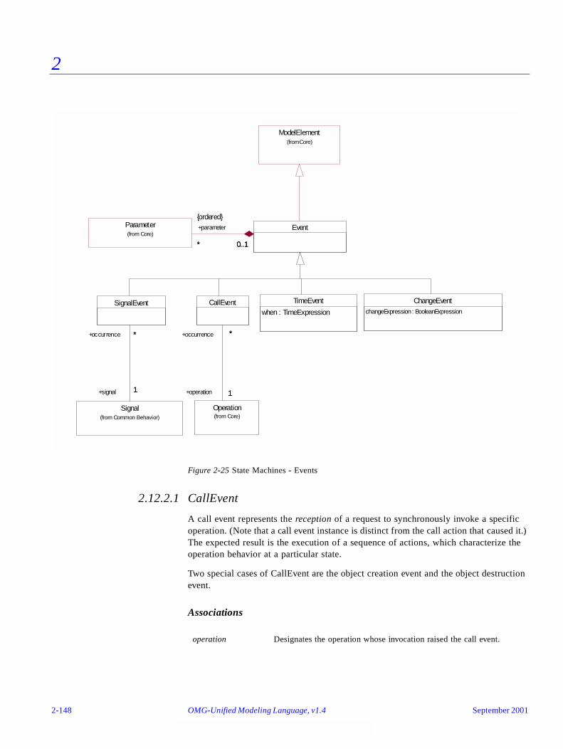
2
Figure 2-25 State Machines - Events
2.12.2.1 CallEvent
A call event represents the reception of a request to synchronously invoke a specific operation. (Note that a call event instance is distinct from the call action that caused it.) The expected result is the execution of a sequence of actions, which characterize the operation behavior at a particular state.
Two special cases of CallEvent are the object creation event and the object destruction event.
Associations
operation Designates the operation whose invocation raised the call event.
TimeEvent
when : TimeExpression
ChangeEventchangeExpression : BooleanExpression
Operation(from Core)
CallEvent
1
*
+operation 1
+occurrence *
SignalEvent
Signal(from Common Behavior)
*
1
+occurrence *
+signal 1
Parameter(from Core)
Event
* 0..1
+parameter
*
{ordered}
0..1
ModelElement(from Core)
2-148 OMG-Unified Modeling Language, v1.4 September 2001

2
Stereotypes
2.12.2.2 ChangeEvent
A change event models an event that occurs when an explicit boolean expression becomes true as a result of a change in value of one or more attributes or associations. A change event is raised implicitly and is not the result of some explicit change event action.
The change event should not be confused with a guard. A guard is only evaluated at the time an event is dispatched whereas, conceptually, the boolean expression associated with a change event is evaluated continuously until it becomes true. The event that is generated remains until it is consumed even if the boolean expression changes to false after that.
Attributes
2.12.2.3 CompositeState
A composite state is a state that contains other state vertices (states, pseudostates, etc.). The association between the composite and the contained vertices is a composition association. Hence, a state vertex can be a part of at most one composite state.
Any state enclosed within a composite state is called a substate of that composite state. It is called a direct substate when it is not contained by any other state; otherwise, it is referred to as a transitively nested substate.
CompositeState is a child of State.
Associations
«create» Create is a stereotyped call event denoting that the instance receiving that event has just been created. For state machines, it triggers the initial transition at the topmost level of the state machine (and is the only kind of trigger that may be applied to an initial transition).
«destroy» Destroy is a stereotyped call event denoting that the instance receiving the event is being destroyed.
changeExpression The boolean expression that specifies the change event.
subvertex The set of state vertices that are owned by this composite state.
September 2001 OMG-UML , v1.4 State Machines 2-149
2
Attributes
2.12.2.4 Event
An event is a specification of a type of observable occurrence. The occurrence that generates an event instance is assumed to take place at an instant in time with no duration.
Strictly speaking, the term “event” is used to refer to the type and not to an instance of the type. However, on occasion, where the meaning is clear from the context, the term is also used to refer to an event instance.
Event is a child of ModelElement.
Associations
2.12.2.5 FinalState
A special kind of state signifying that the enclosing composite state is completed. If the enclosing state is the top state, then it means that the entire state machine has completed.
A final state cannot have any outgoing transitions.
FinalState is a child of State.
2.12.2.6 Guard
A guard is a boolean expression that is attached to a transition as a fine-grained control over its firing. The guard is evaluated when an event instance is dispatched by the state machine. If the guard is true at that time, the transition is enabled, otherwise, it is disabled.
Guards should be pure expressions without side effects. Guard expressions with side effects are ill formed.
Guard is a child of ModelElement.
isConcurrent A boolean value that specifies the decomposition semantics. If this attribute is true, then the composite state is decomposed directly into two or more orthogonal conjunctive components called regions (usually associated with concurrent execution). If this attribute is false, then there are no direct orthogonal components in the composite.
isRegion A derived boolean value that indicates whether a CompositeState is a substate of a concurrent state. If it is true, then this composite state is a direct substate of a concurrent state.
parameter The list of parameters defined by the event.
2-150 OMG-Unified Modeling Language, v1.4 September 2001
2
Attributes
2.12.2.7 PseudoState
A pseudostate is an abstraction that encompasses different types of transient vertices in the state machine graph. They are used, typically, to connect multiple transitions into more complex state transitions paths. For example, by combining a transition entering a fork pseudostate with a set of transitions exiting the fork pseudostate, we get a compound transition that leads to a set of concurrent target states.
The following pseudostate kinds are defined:
• An initial pseudostate represents a default vertex that is the source for a single transition to the default state of a composite state. There can be at most one initial vertex in a composite state.
• deepHistory is used as a shorthand notation that represents the most recent active configuration of the composite state that directly contains this pseudostate; that is, the state configuration that was active when the composite state was last exited. A composite state can have at most one deep history vertex. A transition may originate from the history connector to the default deep history state. This transition is taken in case the composite state had never been active before.
• shallowHistory is a shorthand notation that represents the most recent active substate of its containing state (but not the substates of that substate). A composite state can have at most one shallow history vertex. A transition coming into the shallow history vertex is equivalent to a transition coming into the most recent active substate of a state. A transition may originate from the history connector to the initial shallow history state. This transition is taken in case the composite state had never been active before.
• join vertices serve to merge several transitions emanating from source vertices in different orthogonal regions. The transitions entering a join vertex cannot have guards.
• fork vertices serve to split an incoming transition into two or more transitions terminating on orthogonal target vertices. The segments outgoing from a fork vertex must not have guards.
• junction vertices are semantic-free vertices that are used to chain together multiple transitions. They are used to construct compound transition paths between states. For example, a junction can be used to converge multiple incoming transitions into a single outgoing transition representing a shared transition path (this is known as a merge). Conversely, they can be used to split an incoming transition into multiple outgoing transition segments with different guard conditions. This realizes a static conditional branch. (In the latter case, outgoing transitions whose guard conditions evaluate to false are disabled. A predefined guard denoted “else” may be defined for at most one outgoing transition. This transition is enabled if all the guards labeling the other transitions are false.) Static conditional branches are distinct from dynamic conditional branches that are realized by choice vertices (described below).
expression The boolean expression that specifies the guard.
September 2001 OMG-UML , v1.4 State Machines 2-151
2
• choice vertices which, when reached, result in the dynamic evaluation of the guards of its outgoing transitions. This realizes a dynamic conditional branch. It allows splitting of transitions into multiple outgoing paths such that the decision on which path to take may be a function of the results of prior actions performed in the same run-to-completion step. If more than one of the guards evaluates to true, an arbitrary one is selected. If none of the guards evaluates to true, then the model is considered ill formed. (To avoid this, it is recommended to define one outgoing transition with the predefined “else” guard for every choice vertex.) Choice vertices should be distinguished from static branch points that are based on junction points (described above).
PseudoState is a child of StateVertex.
Attributes
2.12.2.8 SignalEvent
A signal event represents the reception of a particular (asynchronous) signal. A signal event instance should not be confused with the action, such as send action, that generated it.
SignalEvent is a child of Event.
Associations
2.12.2.9 SimpleState
A SimpleState is a state that does not have substates. It is a child of State.
2.12.2.10 State
A state is an abstract metaclass that models a situation during which some (usually implicit) invariant condition holds. The invariant may represent a static situation such as an object waiting for some external event to occur. However, it can also model dynamic conditions such as the process of performing some activity; that is, the model element under consideration enters the state when the activity commences and leaves it as soon as the activity is completed.
State is a child of StateVertex.
kind Determines the precise type of the PseudoState and can be one of initial, deepHistory, shallowHistory, join, fork, junction, or choice.
signal The specific signal that is associated with this event.
2-152 OMG-Unified Modeling Language, v1.4 September 2001

2
Associations
2.12.2.11 StateMachine
A state machine is a specification that describes all possible behaviors of some dynamic model element. Behavior is modeled as a traversal of a graph of state nodes interconnected by one or more joined transition arcs that are triggered by the dispatching of series of event instances. During this traversal, the state machine executes a series of actions associated with various elements of the state machine.
StateMachine has a composition relationship to State, which represents the top-level state, and a set of transitions. This means that a state machine owns its transitions and its top state. All remaining states are transitively owned through the state containment hierarchy rooted in the top state. The association to ModelElement provides the context of the state machine. A common case of the context relation is where a state machine is used to specify the lifecycle of a classifier.
Associations
deferrableEvent A list of events that are candidates to be retained by the state machine if they trigger no transitions out of the state (not consumed).
entry An optional action that is executed whenever this state is entered regardless of the transition taken to reach the state. If defined, entry actions are always executed to completion prior to any internal activity or transitions performed within the state.
exit An optional action that is executed whenever this state is exited regardless of which transition was taken out of the state. If defined, exit actions are always executed to completion only after all internal activities and transition actions have completed execution.
doActivity An optional activity that is executed while being in the state. The execution starts when this state is entered, and stops either by itself, or when the state is exited, whichever comes first.
internalTransition A set of transitions that, if triggered, occur without exiting or entering this state. Thus, they do not cause a state change. This means that the entry or exit condition of the State will not be invoked. These transitions can be taken even if the state machine is in one or more regions nested within this state.
context An association to the model element whose behavior is specified by this state machine. A model element may have more than one state machine (although one is sufficient for most purposes). Each state machine is optionally owned by one model element.
September 2001 OMG-UML , v1.4 State Machines 2-153
2
2.12.2.12 StateVertex
A StateVertex is an abstraction of a node in a statechart graph. In general, it can be the source or destination of any number of transitions.
StateVertex is a child of ModelElement.
Associations
2.12.2.13 StubState
A stub state can appear within a submachine state and represents an actual subvertex contained within the referenced state machine. It can serve as a source or destination of transitions that connect a state vertex in the containing state machine with a subvertex in the referenced state machine.
StubState is a child of State.
Associations
2.12.2.14 SubmachineState
A submachine state is a syntactical convenience that facilitates reuse and modularity. It is a shorthand that implies a macro-like expansion by another state machine and is semantically equivalent to a composite state. The state machine that is inserted is called the referenced state machine while the state machine that contains the submachine state is called the containing state machine. The same state machine may be referenced more than once in the context of a single containing state machine. In effect, a submachine state represents a “call” to a state machine “subroutine” with one or more entry and exit points.
The entry and exit points are specified by stub states.
top Designates the top-level state that is the root of the state containment hierarchy. There is exactly one state in every state machine that is the top state.
transition The set of transitions owned by the state machine. Note that internal transitions are owned by their containing states and not by the state machine.
outgoing Specifies the transitions departing from the vertex.
incoming Specifies the transitions entering the vertex.
container The composite state that contains this state vertex.
referenceState Designates the referenced state as a pathname (a name formed by the concatenation of the name of a state and the successive names of all states that contain it, up to the top state).
2-154 OMG-Unified Modeling Language, v1.4 September 2001

2
SubmachineState is a child of State.
Associations
2.12.2.15 SynchState
A synch state is a vertex used for synchronizing the concurrent regions of a state machine. It is different from a state in the sense that it is not mapped to a boolean value (active, not active), but an integer. A synch state is used in conjunction with forks and joins to insure that one region leaves a particular state or states before another region can enter a particular state or states.
SynchState is a child of StateVertex.
Attributes
2.12.2.16 TimeEvent
A TimeEvent models the expiration of a specific deadline. Note that the time of occurrence of a time event instance; that is, the expiration of the deadline is the same as the time of its reception. However, it is important to note that there may be a variable delay between the time of reception and the time of dispatching (for example, due to queueing delays).
The expression specifying the deadline may be relative or absolute. If the time expression is relative and no explicit starting time is defined, then it is relative to the time of entry into the source state of the transition triggered by the event. In the latter case, the time event instance is generated only if the state machine is still in that state when the deadline expires.
Attributes
2.12.2.17 Transition
A transition is a directed relationship between a source state vertex and a target state vertex. It may be part of a compound transition, which takes the state machine from one state configuration to another, representing the complete response of the state machine to a particular event instance.
submachine The state machine that is to be substituted in place of the submachine state.
bound A positive integer or the value “unlimited” specifying the maximal count of the SynchState. The count is the difference between the number of times the incoming and outgoing transitions of the synch state are fired.
when Specifies the corresponding time deadline.
September 2001 OMG-UML , v1.4 State Machines 2-155

2
Transition is a child of ModelElement.
Associations
2.12.3 Well-FormednessRules
The following well-formedness rules apply to the State Machines package.
2.12.3.1 CompositeState
[1] A composite state can have at most one initial vertex.
self.subvertex->select (v | v.oclIsKindOf(Pseudostate))->
select(p : Pseudostate | p.kind = #initial)->size <= 1
[2] A composite state can have at most one deep history vertex.
self.subvertex->select (v | v.oclIsKindOf(Pseudostate))->
select(p : Pseudostate | p.kind = #deepHistory)->size <= 1
[3] A composite state can have at most one shallow history vertex.
self.subvertex->select(v | v.oclIsKindOf(Pseudostate))->
select(p : Pseudostate | p.kind = #shallowHistory)->size <= 1
[4] There have to be at least two composite substates in a concurrent composite state.
(self.isConcurrent) implies
(self.subvertex->select (v | v.oclIsKindOf(CompositeState))->size >= 2)
[5] A concurrent state can only have composite states as substates.
(self.isConcurrent) impliesself.subvertex->forAll(s | (s.oclIsKindOf(CompositeState))
trigger Specifies the event that fires the transition. There can be at most one trigger per transition.
guard A boolean predicate that provides a fine-grained control over the firing of the transition. It must be true for the transition to be fired. It is evaluated at the time the event is dispatched. There can be at most one guard per transition.
effect Specifies an optional action to be performed when the transition fires.
source Designates the originating state vertex (state or pseudostate) of the transition.
target Designates the target state vertex that is reached when the transition is taken.
2-156 OMG-Unified Modeling Language, v1.4 September 2001
2
[6] The substates of a composite state are part of only that composite state.
self.subvertex->forAll(s | (s.container->size = 1) and (s.container = self))
2.12.3.2 FinalState
[1] A final state cannot have any outgoing transitions.
self.outgoing->size = 0
2.12.3.3 Guard
[1] A guard should not have side effects.
self.transition->stateMachine->notEmpty implies post: (self.transition.stateMachine->context = self.transition.stateMachine->context@pre)
2.12.3.4 PseudoState
[1] An initial vertex can have at most one outgoing transition and no incoming transitions.
(self.kind = #initial) implies
((self.outgoing->size <= 1) and (self.incoming->isEmpty))
[2] History vertices can have at most one outgoing transition.
((self.kind = #deepHistory) or (self.kind = #shallowHistory)) implies
(self.outgoing->size <= 1)
[3] A join vertex must have at least two incoming transitions and exactly one outgoingtransition.
(self.kind = #join) implies
((self.outgoing->size = 1) and (self.incoming->size >= 2))
[4] All transitions incoming a join vertex must originate in different regions of a concurrentstate.
(self.kind = #join and not oclIsKindOf(self.stateMachine, ActivityGraph))
implies self.incoming->forAll (t1, t2 | t1<>t2 implies
(self.stateMachine.LCA(t1.source, t2.source).container.isConcurrent)
[5] A fork vertex must have at least two outgoing transitions and exactly one incomingtransition.
(self.kind = #fork) implies
((self.incoming->size = 1) and (self.outgoing->size >= 2))
[6] All transitions outgoing a fork vertex must target states in different regions of a concurrentstate.
September 2001 OMG-UML , v1.4 State Machines 2-157
2
(self.kind = #fork and not oclIsKindOf(self.stateMachine, ActivityGraph)) implies self.outgoing->forAll (t1, t2 | t1<>t2 implies
(self.stateMachine.LCA(t1.target, t2.target).container.isConcurrent)
[7] A junction vertex must have at least one incoming and one outgoing transition.
(self.kind = #junction) implies
((self.incoming->size >= 1) and (self.outgoing->size >= 1))
[8] A choice vertex must have at least one incoming and one outgoing transition.
(self.kind = #choice) implies
((self.incoming->size >= 1) and (self.outgoing->size >= 1))
2.12.3.5 StateMachine
[1] A StateMachine is aggregated within either a classifier or a behavioral feature.
self.context.notEmpty implies
(self.context.oclIsKindOf(BehavioralFeature) or
self.context.oclIsKindOf(Classifier))
[2] A top state is always a composite.
self.top.oclIsTypeOf(CompositeState)
[3] A top state cannot have any containing states.
self.top.container->isEmpty
[4] The top state cannot be the source of a transition.
(self.top.outgoing->isEmpty)
[5] If a StateMachine describes a behavioral feature, it contains no triggers of type CallEvent,apart from the trigger on the initial transition (see OCL for Transition [8]).
self.context.oclIsKindOf(BehavioralFeature) implies
self.transitions->reject(
source.oclIsKindOf(Pseudostate) and
source.oclAsType(Pseudostate).kind= #initial).trigger->isEmpty
Additional Operations
[1] The operation LCA(s1,s2) returns the state that is the least common ancestor of states s1and s2.
context StateMachine::LCA (s1 : State, s2 : State) : CompositeState
2-158 OMG-Unified Modeling Language, v1.4 September 2001
2
result = if ancestor (s1, s2) then s1
else if ancestor (s2, s1) then s2
else (LCA (s1.container, s2.container))
[2] The query ancestor(s1, s2) checks whether s2 is an ancestor state of state s1.
context StateMachine::ancestor (s1 : State, s2 : State) : Boolean
result = if (s2 = s1) then true
else if (s1.container->isEmpty) then true
else if (s2.container->isEmpty) then false
else (ancestor (s1, s2.container)
2.12.3.6 SynchState
[1] The value of the bound attribute must be a positive integer, or unlimited.
(self.bound > 0) or (self.bound = unlimited)
[2] All incoming transitions to a SynchState must come from the same region and all outgoingtransitions from a SynchState must go to the same region.
2.12.3.7 SubmachineState
[1] Only stub states allowed as substates of a submachine state.
self.subvertex->forAll (s | s.oclIsTypeOf(StubState))
[2] Submachine states are never concurrent.
self.isConcurrent = false
2.12.3.8 Transition
[1] A fork segment should not have guards or triggers.
(self.source.oclIsKindOf(Pseudostate) and not oclIsKindOf(self.stateMachine, ActivityGraph)) implies
((self.source.oclAsType(Pseudostate).kind = #fork) implies
((self.guard->isEmpty) and (self.trigger->isEmpty)))
[2] A join segment should not have guards or triggers.
self.target.oclIsKindOf(Pseudostate) implies
((self.target.oclAsType(Pseudostate).kind = #join) implies
((self.guard->isEmpty) and (self.trigger->isEmpty)))
[3] A fork segment should always target a state.
September 2001 OMG-UML , v1.4 State Machines 2-159

2
(self.stateMachine->notEmpty and not oclIsKindOf(self.stateMachine, ActivityGraph)) implies
self.source.oclIsKindOf(Pseudostate) implies
((self.source.oclAsType(Pseudostate).kind = #fork) implies
(self.target.oclIsKindOf(State)))
[4] A join segment should always originate from a state.
(self.stateMachine->notEmpty and not oclIsKindOf(self.stateMachine, ActivityGraph))
implies
self.target.oclIsKindOf(Pseudostate) implies
((self.target.oclAsType(Pseudostate).kind = #join) implies
(self.source.oclIsKindOf(State)))
[5] Transitions outgoing pseudostates may not have a trigger.
self.source.oclIsKindOf(Pseudostate) implies (self.trigger->isEmpty))
[6] An initial transition at the topmost level either has no trigger or it has a trigger with thestereotype "create.”
self.source.oclIsKindOf(Pseudostate) implies(self.source.oclAsType(Pseudostate).kind = #initial) implies
(self.source.container = self.stateMachine.top) implies((self.trigger->isEmpty) or (self.trigger.stereotype.name = 'create'))
2.12.4 Detailed Semantics
This section describes the execution semantics of state machines. For convenience, the semantics are described in terms of the operations of a hypothetical machine that implements a state machine specification. This is for reference purposes only. Individual realizations are free to choose any form that achieves the same semantics.
In the general case, the key components of this hypothetical machine are:
• an event queue that holds incoming event instances until they are dispatched .
• an event dispatcher mechanism that selects and de-queues event instances from the event queue for processing
• an event processor that processes dispatched event instances according to the general semantics of UML state machines and the specific form of the state machine in question. Because of that, this component is simply referred to as the “state machine” in the following text.
Although the intent is to define the semantics of state machines very precisely, there are a number of semantic variation points to allow for different semantic interpretations that might be required in different domains of application. These are clearly identified in the text.
2-160 OMG-Unified Modeling Language, v1.4 September 2001
2
The basic semantics of events, states, transitions are discussed first in separate subsections under the appropriate headings. The operation of the state machine as a whole are then described in the state machine subsection.
2.12.4.1 Event
Event instances are generated as a result of some action either within the system or in the environment surrounding the system. An event is then conveyed to one or more targets. The means by which event instances are transported to their destination depend on the type of action, the target, the properties of the communication medium, and numerous other factors. In some cases, this is practically instantaneous and completely reliable while in others it may involve variable transmission delays, loss of events, reordering, or duplication. No specific assumptions are made in this regard. This provides full flexibility for modeling different types of communication facilities.
An event is received when it is placed on the event queue of its target. An event is dispatched when it is dequeued from the event queue and delivered to the state machine for processing. At this point, it is referred to as the current event. Finally, it is consumed when event processing is completed. A consumed event is no longer available for processing. No assumptions are made about the time intervals between event reception, event dispatching, and consumption. This leaves open the possibility of different semantic models such as zero-time semantics.
Any parameter values associated with the current event are available to all actions directly caused by that event (transition actions, entry actions, etc.).
Event generalization may be defined explicitly by a signal taxonomy in the case of signal events, or implicitly defined by event expressions, as in time events.
2.12.4.2 State
Active states
A state can be active or inactive during execution. A state becomes active when it is entered as a result of some transition, and becomes inactive if it is exited as a result of a transition. A state can be exited and entered as a result of the same transition (e.g., self transition).
State entry and exit
Whenever a state is entered, it executes its entry action before any other action is executed. Conversely, whenever a state is exited, it executes its exit action as the final step prior to leaving the state.
If defined, the activity associated with a state is forked as a concurrent activity at the instant when the entry action of the state is completed. Upon exit, the activity is terminated before the exit action is executed.
September 2001 OMG-UML , v1.4 State Machines 2-161

2
Activity in state (do-activity)
The activity represents the execution of a sequence of actions, that occurs while the state machine is in the corresponding state. The activity starts executing upon entering the state, following the entry action. If the activity completes while the state is still active, it raises a completion event. In cases where there is an outgoing completion transition (see below) the state will be exited. If the state is exited as a result of the firing of an outgoing transition before the completion of the activity, the activity is aborted prior to its completion.
Deferred events
A state may specify a set of event types that may be deferred in that state. An event instance that does not trigger any transitions in the current state, will not be dispatched if its type matches one of the types in the deferred event set of that state. Instead, it remains in the event queue while another non-deferred message is dispatched instead. This situation persists until a state is reached where either the event is no longer deferred or where the event triggers a transition.
2.12.4.3 CompositeState
Active state configurations
When dealing with composite and concurrent states, the simple term “current state” can be quite confusing. In a hierarchical state machine more than one state can be active at once. If the state machine is in a simple state that is contained in a composite state, then all the composite states that either directly or transitively contain the simple state are also active. Furthermore, since some of the composite states in this hierarchy may be concurrent, the current active “state” is actually represented by a tree of states starting with the single top state at the root down to individual simple states at the leaves. We refer to such a state tree as a state configuration.
Except during transition execution, the following invariants always apply to state configurations:
• If a composite state is active and not concurrent, exactly one of its substates is active.
• If the composite state is active and concurrent, all of its substates (regions) are active.
Entering a non-concurrent composite state
Upon entering a composite state, the following cases are differentiated:
• Default entry: Graphically, this is indicated by an incoming transition that terminates on the outside edge of the composite state. In this case, the default transition is taken. If there is a guard on the transition it must be enabled (true). (A disabled initial transition is an ill-defined execution state and its handling is not defined.) The entry action of the state is executed before the action associated with the initial transition.
2-162 OMG-Unified Modeling Language, v1.4 September 2001

2
• Explicit entry: If the transition goes to a substate of the composite state, then that substate becomes active and its entry code is executed after the execution of the entry code of the composite state. This rule applies recursively if the transition terminates on a transitively nested substate.
• Shallow history entry: If the transition terminates on a shallow history pseudostate, the active substate becomes the most recently active substate prior to this entry, unless the most recently active substate is the final state or if this is the first entry into this state. In the latter two cases, the default history state is entered. This is the substate that is target of the transition originating from the history pseudostate. (If no such transition is specified, the situation is illegal and its handling is not defined.) If the active substate determined by history is a composite state, then it proceeds with its default entry.
• Deep history entry: The rule here is the same as for shallow history except that the rule is applied recursively to all levels in the active state configuration below this one.
Entering a concurrent composite state
Whenever a concurrent composite state is entered, each one of its concurrent substates (regions) is also entered, either by default or explicitly. If the transition terminates on the edge of the composite state, then all the regions are entered using default entry. If the transition explicitly enters one or more regions (in case of a fork), these regions are entered explicitly and the others by default.
Exiting non-concurrent state
When exiting from a composite state, the active substate is exited recursively. This means that the exit actions are executed in sequence starting with the innermost active state in the current state configuration.
Exiting a concurrent state
When exiting from a concurrent state, each of its regions is exited. After that, the exit actions of the regions are executed.
Deferred events
An event that is deferred in a composite state is automatically deferred in all directly or transitively nested substates.
2.12.4.4 FinalState
When the final state is active, its containing composite state is completed, which means that it satisfies the completion condition. If the containing state is the top state, the entire state machine terminates, implying the termination of the entity associated with the state machine. If the state machine specifies the behavior of a classifier, it implies the “termination” of that instance.
September 2001 OMG-UML , v1.4 State Machines 2-163

2
2.12.4.5 SubmachineState
A submachine state is a convenience that does not introduce any additional dynamic semantics. It is semantically equivalent to a composite state and may have entry and exit actions, internal transitions, and activities.
2.12.4.6 Transitions
High-level transitions
Transitions originating from the boundary of composite states are called high-level or group transitions. If triggered, they result in exiting of all the substates of the composite state executing their exit actions starting with the innermost states in the active state configuration. Note that in terms of execution semantics, a high-level transition does not add specialized semantics, but rather reflects the semantics of exiting a composite state.
Compound transitions
A compound transition is a derived semantic concept, represents a “semantically complete” path made of one or more transitions, originating from a set of states (as opposed to pseudo-state) and targeting a set of states. The transition execution semantics described below refer to compound transitions.
In general, a compound transition is an acyclical unbroken chain of transitions joined via join, junction, choice, or fork pseudostates that define path from a set of source states (possibly a singleton) to a set of destination states, (possibly a singleton). For self-transitions, the same state acts as both the source and the destination set. A (simple) transition connecting two states is therefore a special common case of a compound transition.
The tail of a compound transition may have multiple transitions originating from a set of mutually orthogonal concurrent regions that are joined by a join point.
The head of a compound transition may have multiple transitions originating from a fork pseudostate targeted to a set of mutually orthogonal concurrent regions.
In a compound transition multiple outgoing transitions may emanate from a common junction point. In that case, only one of the outgoing transitions whose guard is true is taken. If multiple transitions have guards that are true, a transition from this set is chosen. The algorithm for selecting such a transition is not specified. Note that in this case, the guards are evaluated before the compound transition is taken.
In a compound transition where multiple outgoing transitions emanate from a common choice point, the outgoing transition whose guard is true at the time the choice point is reached, will be taken. If multiple transitions have guards that are true, one transition from this set is chosen. The algorithm for selecting this transition is not specified. If no guards are true after the choice point has been reached, the model is ill formed.
2-164 OMG-Unified Modeling Language, v1.4 September 2001

2
Internal transitions
An internal transition executes without exiting or re-entering the state in which it is defined. This is true even if the state machine is in a nested state within this state.
Completion transitions and completion events
A completion transition is a transition without an explicit trigger, although it may have a guard defined. When all transition and entry actions and activities in the currently active state are completed, a completion event instance is generated. This event is the implicit trigger for a completion transition. The completion event is dispatched before any other queued events and has no associated parameters. For instance, a completion transition emanating from a concurrent composite state will be taken automatically as soon as all the concurrent regions have reached their final state.
If multiple completion transitions are defined for a state, then they should have mutually exclusive guard conditions.
Enabled (compound) transitions
A transition is enabled if and only if:
• All of its source states are in the active state configuration.
• The trigger of the transition is satisfied by the current event. An event instance satisfies a trigger if it matches the event specified by the trigger. In case of signal events, since signals are generalized concepts, a signal event satisfies a signal event associated with the same signal or a generalization of thereof.
• If there exists at least one full path from the source state configuration to either the target state configuration or to a dynamic choice point in which all guard conditions are true (transitions without guards are treated as if their guards are always true).
Since more than one transition may be enabled by the same event instance, being enabled is a necessary but not sufficient condition for the firing of a transition.
Guards
In a simple transition with a guard, the guard is evaluated before the transition is triggered.
In compound transitions involving multiple guards, all guards are evaluated before a transition is triggered, unless there are choice points along one or more of the paths. The order in which the guards are evaluated is not defined.
If there are choice points in a compound transition, only guards that precede the choice point are evaluated according to the above rule. Guards downstream of a choice point are evaluated if and when the choice point is reached (using the same rule as above). In other words, for guard evaluation, a choice point has the same effect as a state.
Guards should not include expressions causing side effects. Models that violate this are considered ill formed.
September 2001 OMG-UML , v1.4 State Machines 2-165
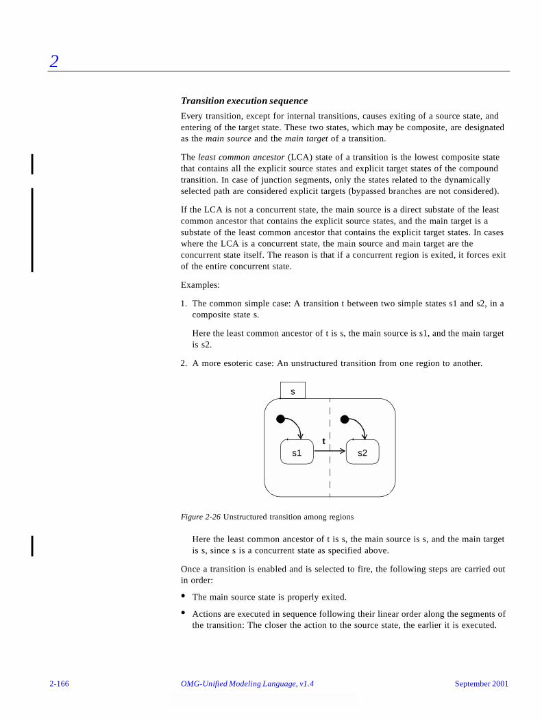
2
Transition execution sequence
Every transition, except for internal transitions, causes exiting of a source state, and entering of the target state. These two states, which may be composite, are designated as the main source and the main target of a transition.
The least common ancestor (LCA) state of a transition is the lowest composite state that contains all the explicit source states and explicit target states of the compound transition. In case of junction segments, only the states related to the dynamically selected path are considered explicit targets (bypassed branches are not considered).
If the LCA is not a concurrent state, the main source is a direct substate of the least common ancestor that contains the explicit source states, and the main target is a substate of the least common ancestor that contains the explicit target states. In cases where the LCA is a concurrent state, the main source and main target are the concurrent state itself. The reason is that if a concurrent region is exited, it forces exit of the entire concurrent state.
Examples:
1. The common simple case: A transition t between two simple states s1 and s2, in a composite state s.
Here the least common ancestor of t is s, the main source is s1, and the main target is s2.
2. A more esoteric case: An unstructured transition from one region to another.
Figure 2-26 Unstructured transition among regions
Here the least common ancestor of t is s, the main source is s, and the main target is s, since s is a concurrent state as specified above.
Once a transition is enabled and is selected to fire, the following steps are carried out in order:
• The main source state is properly exited.
• Actions are executed in sequence following their linear order along the segments of the transition: The closer the action to the source state, the earlier it is executed.
s
s1 s2t
2-166 OMG-Unified Modeling Language, v1.4 September 2001
2
• If a choice point is encountered, the guards following that choice point are evaluated dynamically and a path whose guards are true is selected. Entry and exit actions are executed for states entered and exited by the transition into the choice point.
• The main target state is properly entered.
2.12.4.7 StateMachine
Event processing - run-to-completion step
Events are dispatched and processed by the state machine, one at a time. The order of dequeuing is not defined, leaving open the possibility of modeling different priority-based schemes.
The semantics of event processing is based on the run-to-completion assumption, interpreted as run-to-completion processing. Run-to-completion processing means that an event can only be dequeued and dispatched if the processing of the previous current event is fully completed.
Run-to-completion may be implemented in various ways. For active classes, it may be realized by an event-loop running in its own concurrent thread, and that reads events from a queue. For passive classes it may be implemented as a monitor.
The processing of a single event by a state machine is known as a run-to-completion step. Before commencing on a run-to-completion step, a state machine is in a stable state configuration with all actions (but not necessarily activities) completed. The same conditions apply after the run-to-completion step is completed. Thus, an event will never be processed while the state machine is in some intermediate and inconsistent situation. The run-to-completion step is the passage between two state configurations of the state machine.
The run-to-completion assumption simplifies the transition function of the state machine, since concurrency conflicts are avoided during the processing of event, allowing the state machine to safely complete its run-to-completion step.
When an event instance is dispatched, it may result in one or more transitions being enabled for firing. If no transition is enabled and the event is not in the deferred event list of the current state configuration, the event is discarded and the run-to-completion step is completed.
In the presence of concurrent states it is possible to fire multiple transitions as a result of the same event — as many as one transition in each concurrent state in the current state configuration. In cases where one or more transitions are enabled, the state machine selects a subset and fires them. Which of the enabled transitions actually fire is determined by the transition selection algorithm described below. The order in which selected transitions fire is not defined.
September 2001 OMG-UML , v1.4 State Machines 2-167

2
Each orthogonal region in the active state configuration that is not decomposed into concurrent regions; that is, “bottom-level” region can fire at most one transition as a result of the current event. When all orthogonal regions have finished executing the transition, the current event instance is fully consumed, and the run-to-completion step is completed.
During a transition, a number of actions may be executed. If these actions are synchronous, then the transition step is not completed until the invoked objects complete their own run-to-completion steps.
An event instance can arrive at a state machine that is blocked in the middle of a run-to-completion step from some other object within the same thread, in a circular fashion. This event instance can be treated by orthogonal components of the state machine that are not frozen along transitions at that time.
Run-to-completion and concurrency
It is possible to define state machine semantics by allowing the run-to-completion steps to be applied concurrently to the orthogonal regions of a composite state, rather than to the whole state machine. This would allow the event serialization constraint to be relaxed. However, such semantics are quite subtle and difficult to implement. Therefore, the dynamic semantics defined in this document are based on the premise that a single run-to-completion step applies to the entire state machine and includes the concurrent steps taken by concurrent regions in the active state configuration.
In case of active objects, where each object has its own thread of execution, it is very important to clearly distinguish the notion of run to completion from the concept of thread pre-emption. Namely, run-to-completion event handling is performed by a thread that, in principle, can be pre-empted and its execution suspended in favor of another thread executing on the same processing node. (This is determined by the scheduling policy of the underlying thread environment — no assumptions are made about this policy.) When the suspended thread is assigned processor time again, it resumes its event processing from the point of pre-emption, and eventually completes its event processing.
Conflicting transitions
It was already noted that it is possible for more than one transition to be enabled within a state machine. If that happens, then such transitions may be in conflict with each other. For example, consider the case of two transitions originating from the same state, triggered by the same event, but with different guards. If that event occurs and both guard conditions are true, then only one transition will fire. In other words, in case of conflicting transitions, only one of them will fire in a single run-to-completion step.
Two transitions are said to conflict if they both exit the same state, or, more precisely, that the intersection of the set of states they exit is non-empty. Only transitions that occur in mutually orthogonal regions may be fired simultaneously. This constraint guarantees that the new active state configuration resulting from executing the set of transitions is well formed.
2-168 OMG-Unified Modeling Language, v1.4 September 2001

2
An internal transition in a state conflicts only with transitions that cause an exit from that state.
Firing priorities
In situations where there are conflicting transitions, the selection of which transitions will fire is based in part on an implicit priority. These priorities resolve some transition conflicts, but not all of them. The priorities of conflicting transitions are based on their relative position in the state hierarchy. By definition, a transition originating from a substate has higher priority than a conflicting transition originating from any of its containing states.
The priority of a transition is defined based on its source state. The priority of joined transitions is based on the priority of the transition with the most transitively nested source state.
In general, if t1 is a transition whose source state is s1, and t2 has source s2, then:
• If s1 is a direct or transitively nested substate of s2, then t1 has higher priority than t2.
• If s1 and s2 are not in the same state configuration, then there is no priority difference between t1 and t2.
Transition selection algorithm
The set of transitions that will fire is a maximal set of transitions that satisfies the following conditions:
• All transitions in the set are enabled.
• There are no conflicting transitions within the set.
• There is no transition outside the set that has higher priority than a transition in the set (that is, enabled transitions with highest priorities are in the set while conflicting transitions with lower priorities are left out).
This can be easily implemented by a greedy selection algorithm, with a straightforward traversal of the active state configuration. States in the active state configuration are traversed starting with the innermost nested simple states and working outwards toward the top state. For each state at a given level, all originating transitions are evaluated to determine if they are enabled. This traversal guarantees that the priority principle is not violated. The only non-trivial issue is resolving transition conflicts across orthogonal states on all levels. This is resolved by terminating the search in each orthogonal state once a transition inside any one of its components is fired.
2.12.4.8 Synch States
Synch states provide a means of synchronizing the execution of two concurrent regions. Specifically, a synch state has incoming transitions from a fork (or forks) in one region, the source region, and outgoing transitions to a join (or joins) in another, the target region. These forks and joins are called synchronization forks and joins. The
September 2001 OMG-UML , v1.4 State Machines 2-169
2
synch state itself is contained by the least common ancestor of the two regions being synchronized. The synchronized regions do not need to be siblings in state decomposition, but they must have a common ancestor state.
When the source region reaches a synchronization fork, the target states of that fork become active, including the synch state. Activation of the synch state is an indication that the source region has completed some activity. This region can continue performing its remaining activities in parallel. When the target region reaches the corresponding synchronization join, it is prevented from continuing unless all the states leading into the synchronization join are active, including the synch states.
A synch state may have multiple incoming and outgoing transitions, used for multiple synchronization points in each region. Alternatively, it may have single incoming and outgoing transitions where the incoming transition is fired multiple times before the outgoing one is fired. To support these applications, synch states keep count of the difference between the number of times their incoming and outgoing transitions are fired. When an incoming transition is fired, the count is incremented by one, unless its value is equal to the value defined in the bound attribute. In that case, the count is not incremented. When an outgoing transition is fired, the count is decremented by one. An outgoing transition may fire only if the count is greater than zero, which prevents the count from becoming negative. The count is automatically set to zero when its container state is exited.
The bound attribute is for limiting the number of times outgoing transitions fire from a synch state. For a state to realize the equivalent of a binary semaphore, the bound should be set to one. In this case multiple incoming transitions may fire before the outgoing transition does, whereupon the outgoing transition can only fire once.
2.12.4.9 StubStates
Stub states are pseudostates signifying either entry points to or exit points from a submachine. Since a submachine is encapsulated and represented as a submachine state, multi-level (“deep”) transitions may logically connect states in separate state machines. This is facilitated by stub state, representing real states in a referenced machine to or form transitions in the referencing machine are incoming/outgoing. Stub states are therefore only defined within a submachine state, and are the only potential subvertices of a submachine state.
2.12.5 Notes
2.12.5.1 Protocol State Machines
One application area of state machines is in specifying object protocols, also known as object life cycles. A ‘protocol state machine’ for a class defines the order; that is, sequence in which the operations of that Class can be invoked. The behavior of each of these operations is defined by an associated method, rather than through action expressions on transitions.
2-170 OMG-Unified Modeling Language, v1.4 September 2001
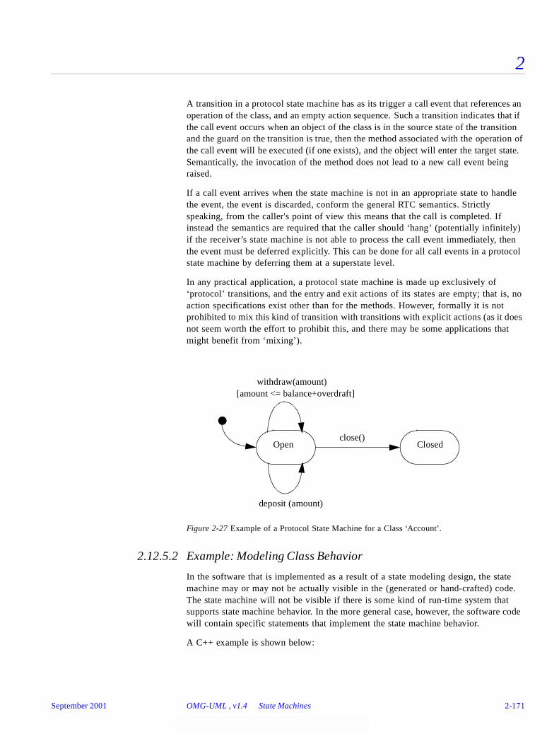
2
A transition in a protocol state machine has as its trigger a call event that references an operation of the class, and an empty action sequence. Such a transition indicates that if the call event occurs when an object of the class is in the source state of the transition and the guard on the transition is true, then the method associated with the operation of the call event will be executed (if one exists), and the object will enter the target state. Semantically, the invocation of the method does not lead to a new call event being raised.
If a call event arrives when the state machine is not in an appropriate state to handle the event, the event is discarded, conform the general RTC semantics. Strictly speaking, from the caller's point of view this means that the call is completed. If instead the semantics are required that the caller should ‘hang’ (potentially infinitely) if the receiver’s state machine is not able to process the call event immediately, then the event must be deferred explicitly. This can be done for all call events in a protocol state machine by deferring them at a superstate level.
In any practical application, a protocol state machine is made up exclusively of ‘protocol’ transitions, and the entry and exit actions of its states are empty; that is, no action specifications exist other than for the methods. However, formally it is not prohibited to mix this kind of transition with transitions with explicit actions (as it does not seem worth the effort to prohibit this, and there may be some applications that might benefit from ‘mixing’).
Figure 2-27 Example of a Protocol State Machine for a Class ‘Account’.
2.12.5.2 Example: Modeling Class Behavior
In the software that is implemented as a result of a state modeling design, the state machine may or may not be actually visible in the (generated or hand-crafted) code. The state machine will not be visible if there is some kind of run-time system that supports state machine behavior. In the more general case, however, the software code will contain specific statements that implement the state machine behavior.
A C++ example is shown below:
Open Closedclose()
withdraw(amount)[amount <= balance+overdraft]
deposit (amount)
September 2001 OMG-UML , v1.4 State Machines 2-171

2
class bankAccount {private:
int balance;public:
void deposit (amount) {if (balance > 0)
balance = balance + amount’ // no changeelse
balance = balance + amount - 1; // transaction fee}
void withdrawal (amount) {if (balance>0)
balance = balance - amount;}
}
In the above example, the class has an abstract state manifested by the balance attribute, controlling the behavior of the class. This is modeled by the state machine in Figure 2-28 on page 2-172.
Figure 2-28 State Machine for Modeling Class Behavior
2.12.5.3 Example: State machine refinement
Note – The following discussion provides some potentially useful heuristics on how state machines can be refined. These techniques are all based on practical experience. However, readers are reminded that this topic is still the subject of research, and that it is likely that other approaches may be defined either now or in the future.
Since state machines describe behaviors of generalizable elements, primarily classes, state machine refinement is used to capture the relationships between the corresponding state machines. State machines use refinement in three different mappings, specified by the mapping attribute of the refinement meta-class. The mappings are refinement, substitution, and deletion.
credit
debit
withdrawal
deposit/balance+=amount
deposit
[amount>-balance]/balance+=amount-1
else/balance -= amount
else/balance+=amount-1
[amount>balance]/balance -= amount
2-172 OMG-Unified Modeling Language, v1.4 September 2001

2
To illustrate state machine refinement, consider the following example where one state machine attached to a class denoted ‘Supplier,’ is refined by another state machine attached to a class denoted as ‘Client.’
Figure 2-29 State Machine Refinement Example
In the example above, the client state (Sa(new)) in the subclass substitutes the simple substate (Sa1) by a composite substate (Sa1(new)). This new composite substate has a component substate (Sa11). Furthermore, the new version of Sa1 deletes the substate Sa2 and also adds a new substate Sa4. Substate Sa3 is inherited and is therefore common to both versions of Sa. For clarity, we have used a gray shading to identify components that have been inherited from the original. (This is for illustration purposes and is not intended as a notational recommendation.)
It is important to note that state machine refinement as defined here does not specify or favor any specific policy of state machine refinement. Instead, it simply provides a flexible mechanism that allows subtyping, (behavioral compatibility), inheritance (implementation reuse), or general refinement policies.
We provide a brief discussion of potentially useful policies that can be implemented with the state machine refinement mechanism.
Subtyping
The refinement policy for subtyping is based on the rationale that the subtype preserves the pre/post condition relationships of applying events/operations on the type, as specified by the state machine. The pre/post conditions are realized by the states, and the relationships are realized by the transitions. Preserving pre/post conditions guarantee the substitutability principle.
States and transitions are only added, not deleted. Refinement is interpreted as follows:
• A refined state has the same outgoing transitions, but may add others, and a different set of incoming transitions. It may have a bigger set of substates, and it may change its concurrency property from false to true.
Sa
Sa2
Sa1
Sa3
Sa (new)
Sa4Sa1 (new)
Sa3Sa11
- Sa2 deleted
- Sa4 added
- Sa1 refinedinto composite
Supplier (refined) Client (refined)
September 2001 OMG-UML , v1.4 State Machines 2-173
2
• A refined transition may go to a new target state which is a substate of the state specified in the base class. This comes to guarantee the post condition specified by the base class.
• A refined guard has the same guard condition, but may add disjunctions. This guarantees that pre-conditions are weakened rather than strengthened.
• A refined action sequence contains the same actions (in the same sequence), but may have additional actions. The added actions should not hinder the invariant represented by the target state of the transition.
Strict Inheritance
The rationale behind this policy is to encourage reuse of implementation rather than preserving behavior. Since most implementation environments utilize strict inheritance; that is, features can be replaced or added, but not deleted, the inheritance policy follows this line by disabling refinements that may lead to non-strict inheritance once the state machine is implemented.
States and transitions can be added. Refinement is interpreted as follows:
• A refined state has some of the same incoming transitions (i.e., drop some, add some) but a greater or bigger set of outgoing transitions. It may have more substates, and may change its concurrency attribute.
• A refined transition may go to a new target state but should have the same source.
• A refined guard may have a different guard condition.
• A refined action sequence contains some of the same actions (in the same sequence), and may have additional actions.
General Refinement
In this most general case, states and transitions can be added and deleted (i.e., ‘null’ refinements). Refinement is interpreted without constraints; that is, there are no formal requirements on the properties and relationships of the refined state machine element and the refining element:
• A refined state may have different outgoing and incoming transitions (i.e., drop all, add some).
• A refined transition may leave from a different source and go to a new target state.
• A refined guard has may have a different guard condition.
• A refined action sequence need not contain the same actions (or it may change their sequence), and may have additional actions.
The refinement of the composite state in the example above is an illustration of general refinement.
It should be noted that if a type has multiple supertype relationships in the structural model, then the default state machine for the type consists of all the state machines of its supertypes as orthogonal state machine regions. This may be explicitly overridden through refinement if required.
2-174 OMG-Unified Modeling Language, v1.4 September 2001

2
2.12.5.4 Comparison to classical statecharts
The major difference between classical (Harel) statecharts and object state machines results from the external context of the state machine. Object state machines, such as ROOMcharts, primarily come to represent behavior of a type. Classical statechart specify behaviors of processes. The following list of differences result from the above rationale:
• Events carry parameters, rather than being primitive signals.
• Call events (operation triggers) are supported to model behaviors of types.
• Event conjunction is not supported, and the semantics is given in respect to a single event dispatch, to better match the type context as opposed to a general system context.
• Classical statecharts have an elaborated set of predefined actions, conditions and events that are not mandated by object state machines, such as entered(s), exited(s), true(condition), tr!(c) (make true), fs!(c).
• Operations are not broadcast but can be directed to an object-set.
• The notion of activities (processes) does not exist in object state machines. Therefore all predefined actions and events that deal with activities are not supported, as well as the relationships between states and activities.
• Transition compositions are constrained for practical reasons. In classical statecharts any composition of pseudostates, simple transitions, guards, and labels is allowed.
• Object state machine supports the notion of synchronous communication between state machines.
• Actions on transitions are executed in their given order.
• Classical statecharts do not support dynamic choice points.
• Classical statecharts are based on the zero-time assumption, meaning transitions take zero time to execute. The whole system execution is based on synchronous steps where each step produces new events that will be processed at the next step. In object-oriented state machines, these assumptions are relaxed and replaced with these of software execution model, based on threads of execution and that execution of actions may take time.
2.13 Activity Graphs
2.13.1 Overview
The Activity Graphs package defines an extended view of the State Machine package. State machines and activity graphs are both essentially state transition systems, and share many metamodel elements. This section describes the concepts in the State Machine package that are specific to activity graphs. It should be noted that the activity
September 2001 OMG-UML , v1.4 Activity Graphs 2-175
2
graphs extension has few semantics of its own. It should be understood in the context of the State Machine package, including its dependencies on the Foundation package and the Common Behavior package.
An activity graph is a special case of a state machine that is used to model processes involving one or more classifiers. Its primary focus is on the sequence and conditions for the actions that are taken, rather than on which classifiers perform those actions. Most of the states in such a graph are action states that represent atomic actions; that is, states that invoke actions and then wait for their completion. Transitions into action states are triggered by events, which can be
• the completion of a previous action state (completion events),
• the availability of an object in a certain state,
• the occurrence of a signal, or
• the satisfaction of some condition.
By defining a small set of additional subtypes to the basic state machine concepts, the well-formedness of activity graphs can be defined formally, and subsequently mapped to the dynamic semantics of state machines. In addition, the activity specific subtypes eliminate ambiguities that might otherwise arise in the interchange of activity graphs between tools.
2.13.2 Abstract Syntax
The abstract syntax for activity graphs is expressed in graphic notation in Figure 2-30 on page 2-177.
2-176 OMG-Unified Modeling Language, v1.4 September 2001

2
Figure 2-30 Activity Graphs
2.13.2.1 ActivityGraph
An activity graph is a special case of a state machine that defines a computational process in terms of the control-flow and object-flow among its constituent actions. It does not extend the semantics of state machines in a major way but it does define shorthand forms that are convenient for modeling control-flow and object-flow in computational and organizational processes.
The primary purpose of activity graphs is to describe the states of an activity or process involving one or more classifiers. Activity graphs can be attached to packages, classifiers (including use cases), and behavioral features. As in any state machine, if an outgoing transition is not explicitly triggered by an event, then it is implicitly triggered
CallState
ActionStateisDynamic : BooleandynamicArguments : ArgListsExpressiondynamicMultiplicity : Multiplicity
SimpleState(from State Machines)
SubactivityStateisDynamic : BooleandynamicArguments : ArgListsExpressiondynamicMultiplicity : Multiplicity
SubmachineState(from State Machines)
CompositeStateisConcurrent : Boolean
ActivityGraph Partition
1 0..*1
+partition
0..*
ModelElement(from Core)
*
*
+contents*
*
StateMachine(from State Machines)
0..1*
+context
0..1
+behavior
*
State(from State Machines)
0..1
1
0..1
+top 1
ClassifierInState
0..*
1..*
0..*
+inState
1..*
Parameter(from Core)
Classifier(from Core)
1
*
+type1
*
ObjectFlowStateisSynch : Boolean
*
*
+parameter*
+state *
1*
+type
1*
September 2001 OMG-UML , v1.4 Activity Graphs 2-177
2
by the completion of the contained actions. A subactivity state represents a nested activity that has some duration and internally consists of a set of actions or more subactivities. That is, a subactivity state is a “hierarchical action” with an embedded activity subgraph that ultimately resolves to individual actions.
Junctions, forks, joins, and synchs may be included to model decisions and concurrent activity.
Activity graphs include the concept of Partitions to organize states according to various criteria, such as the real-world organization responsible for their performance.
Activity graphing can be applied to organizational modeling for business process engineering and workflow modeling. In this context, events often originate from inside the system, such as the finishing of a task, but also from outside the system, such as a customer call. Activity graphs can also be applied to system modeling to specify the dynamics of operations and system level processes when a full interaction model is not needed.
Associations
2.13.2.2 ActionState
An action state represents the execution of an atomic action, typically the invocation of an operation.
An action state is a simple state with an entry action whose only exit transition is triggered by the implicit event of completing the execution of the entry action. The state therefore corresponds to the execution of the entry action itself and the outgoing transition is activated as soon as the action has completed its execution.
An ActionState may perform more than one action as part of its entry action. An action state may not have an exit action, do activity, or internal transitions.
Attributes
partition A set of Partitions each of which contains some of the model elements of the model.
dynamicArguments An ArgListsExpression that determines at runtime the number of parallel executions of the actions of the state. The value must be a set of lists of objects, each list serving as arguments for one execution. This attribute is ignored if the isDynamic attribute is false.
dynamicMultiplicity A Multiplicity limiting the number of parallel executions of the actions of state. This attribute is ignored if the isDynamic attribute is false.
isDynamic A boolean value specifying whether the state's actions might be executed concurrently. It is used in conjunction with the dynamicArguments attribute.
2-178 OMG-Unified Modeling Language, v1.4 September 2001

2
Associations
2.13.2.3 CallState
A call state is an action state that has exactly one call action as its entry action. It is useful in object flow modeling to reduce notational ambiguity over which action is taking input or providing output.
2.13.2.4 ClassifierInState
A classifier-in-state characterizes instances of a given classifier that are in a particular state or states. In an activity graph, it may be used to specify input and/or output to an action through an object flow state.
ClassifierInState is a child of Classifier and may be used in static structural models and collaborations. For example, it can be used to show associations that are only relevant when objects of a class are in a given state.
Associations
2.13.2.5 ObjectFlowState
An object flow state defines an object flow between actions in an activity graph. An instance of a particular classifier, possibly in a particular state, is available when an object flow state is occupied.
The generation of an object by an action in an action state may be modeled by an object flow state that is triggered by the completion of the action state. The use of the object in a subsequent action state may be modeled by connecting the output transition of the object flow state as an input transition to the action state. Generally each action places the object in a different state that is modeled as a distinct object flow state.
Attributes
entry (Inherited from State) Specifies the invoked actions.
type Designates a classifier for the ClassifierInState to characterize the instances of.
inState Designates a state that characterizes instances of the classifier of the ClassifierInState. The state must be a valid state of the corresponding classifier. This may have multiple states when referring to an object in orthogonal states.
isSynch A boolean value indicating whether an object flow state is used as a synch state.
September 2001 OMG-UML , v1.4 Activity Graphs 2-179
2
Associations
Stereotypes
2.13.2.6 Partition
A partition is a mechanism for dividing the states of an activity graph into groups. Partitions often correspond to organizational units in a business model. They may be used to allocate characteristics or resources among the states of an activity graph. It should be noted that Partitions do not impact the dynamic semantics of the model but they help to allocate properties and actions for various purposes.
Associations
2.13.2.7 SubactivityState
A subactivity state represents the execution of a non-atomic sequence of steps that has some duration; that is, internally it consists of a set of actions and possibly waiting for events. That is, a subactivity state is a “hierarchical action,” where an associated subactivity graph is executed.
A subactivity state is a submachine state that executes a nested activity graph. When an input transition to the subactivity state is triggered, execution begins with the nested activity graph. The outgoing transitions of a subactivity state are enabled when the final state of the nested activity graph is reached; that is, when it completes its execution, or when the trigger events occur on the transitions.
The semantics of a subactivity state are equivalent to the model obtained by statically substituting the contents of the nested graph as a composite state replacing the subactivity state.
type Designates a classifier that specifies the classifier of the object. It may be a classifier-in-state to specify the state and classifier of the object.
parameter Designates parameters that provide the object as output or take it as input.
«signalflow» Signalflow is a stereotype of ObjectFlowState with a Signal as its type.
contents Specifies the states that belong to the partition. They need not constitute a nested region.
2-180 OMG-Unified Modeling Language, v1.4 September 2001
2
Attributes
Associations
2.13.2.8 Transition
Transition is inherited from state machines.
Tagged Values
2.13.3 Well-Formedness Rules
2.13.3.1 ActivityGraph
[1] An ActivityGraph specifies the dynamics of
(i) a Package, or
(ii) a Classifier (including UseCase), or
(iii) a BehavioralFeature.
(self.context.oclIsTypeOf(Package) xor
dynamicArguments An ArgListsExpression that determines the number of parallel executions of the submachines of the state. The value must be a set of lists of objects, each list serving as arguments for one execution. This attribute is ignored if the isDynamic attribute is false.
dynamicMultiplicity A Multiplicity limiting the number of parallel executions of the actions of state. This attribute is ignored if the isDynamic attribute is false.
isDynamic A boolean value specifying whether the state's subactivity might be executed concurrently. It is used in conjunction with the dynamicArguments attribute.
submachine (Inherited from SubmachineState) This designates an activity graph that is conceptually nested within the subactivity state. The subactivity state is conceptually equivalent to a composite state whose contents are the states of the nested activity graph. The nested activity graph must have an initial state and a final state.
usage Usage applies only to transitions leading into or out of an object flow state. It has a value of uses or modifies. A value of uses indicates that the action of the state at the other end of the transition from the object flow state uses but does not modify the object represented by the object flow state. A value of modifies indicates that the action of the state at the other end of the transition from the object flow state modifies and may use the object represented by the object flow state.
September 2001 OMG-UML , v1.4 Activity Graphs 2-181
2
self.context.oclIsKindOf(Classifier) xor
self.context.oclIsKindOf(BehavioralFeature))
2.13.3.2 ActionState
[1] An action state has a non-empty entry action.
self.entry->size > 0
[2] An action state does not have an internal transition, exit action, or a do activity.
self.internalTransition->size = 0 and self.exit->size = 0 and self.doActivity->size = 0
[3] Transitions originating from an action state have no trigger event.
self.outgoing->forAll(t | t.trigger->size = 0)
2.13.3.3 CallState
[1] The entry action of a call state is a single call action.
self.entry->size = 1 and self.entry.oclIsKindOf(CallAction)
2.13.3.4 ClassifierInState
[1] Classifiers-in-state have no namespace contents.
self.allContents->size = 0
2.13.3.5 ObjectFlowState
[1] Parameters of an object flow state must have a type and direction compatible withclassifier or classifier-in-state of the object flow state.
let ofstype : Classifier =
(if self.type.IsKindOf(ClassifierInState)
then self.type.type else self.type);
self.parameter->forAll(parameter |
parameter.type = ofstype
or (parameter.kind = #in
and ofstype.allSupertypes->includes(type))
or ((parameter.kind = #out or parameter.kind = #return)
and type.allSupertypes->includes(ofstype))
or (parameter.kind = #inout
and ( ofstype.allSupertypes->includes(type)
or type.allSupertypes->includes(ofstype))))
2-182 OMG-Unified Modeling Language, v1.4 September 2001
2
[2] Downstream states have entry actions that accept input conforming to the type of theclassifier or classifier-in-state. The entry actions use the input parameters of the objectflow state. Valid downstream states are calculated by traversing outgoing transitionstransitively, skipping pseudo states, and entering and exiting subactivity states, looking forregular states. If the object flow state has no parameters, then the target of downstreamactions must conform to the type of the classifier or classifier-in-state.
self.allNextLeafStates.size > 0 and
self.allNextLeafStates->forAll(s | self.isInputAction(s.entry))
[3] Upstream states have entry actions that provide output or return values conforming to thetype of the classifier or classifier-in-state. The entry actions use the output or returnparameters of the object flow state. Valid upstream states are calculated by traversingincoming transitions transitively, skipping pseudo states, entering and exiting subactivitystates, looking for regular states.
self.allPreviousLeafStates.size > 0 and
self.allPreviousLeafStates->forAll(s |
self.isOutputAction(s.entry))
Additional operations
[1] The operation allNextLeafStates results in the set of states immediately downstreamof the object flow state that have the next actions that will be executed.
[2] The operation allPreviousLeafStates results in the set of states immediatelyupstream of the object flow state that have the next actions that were last executed.
[3] The operation isInputAction takes an action as input and results in a boolean tellingwhether the action has an input parameter compatible with the object flow state.
[4] The operation isOutputAction takes an action as input and results in a boolean tellingwhether the action has an output parameter compatible with the object flow state.
2.13.3.6 PseudoState
[1] In activity graphs, transitions incoming to (and outgoing from) join and fork pseudostateshave as sources (targets) any state vertex. That is, joins and forks are syntactically notrestricted to be used in combination with composite states, as is the case in state machines.
self.stateMachine.oclIsTypeOf(ActivityGraph) implies
((self.kind = #join or self.kind = #fork) implies
(self.incoming->forAll(t | t.source.oclIsKindOf(State) or
source.oclIsTypeOf(PseudoState)) and
(self.outgoing->forAll(t | t.source.oclIsKindOf(State) or
source.oclIsTypeOf(PseudoState)))))
[2] All of the paths leaving a fork must eventually merge in a subsequent join in the model.Furthermore, multiple layers of forks and joins must be well nested, with the exception offorks and joins leading to or from synch state. Therefore the concurrency structure of an
September 2001 OMG-UML , v1.4 Activity Graphs 2-183
2
activity graph is in fact equally restrictive as that of an ordinary state machine, eventhough the composite states need not be explicit.
2.13.3.7 SubactivityState
[1] A subactivity state is a submachine state that is linked to an activity graph.
self.submachine.oclIsKindOf(ActivityGraph)
2.13.4 Detailed Semantics
2.13.4.1 ActivityGraph
The dynamic semantics of activity graphs can be expressed in terms of state machines. This means that the process structure of activities formally must be equivalent to orthogonal regions (in composite states). That is, transitions crossing between parallel paths (or threads) are not allowed, except for transitions used with synch states. As such, an activity specification that contains ‘unconstrained parallelism’ as is used in general activity graphs is considered ‘incomplete’ in terms of UML.
All events that are not relevant in a state must be deferred so they are consumed when they become relevant. This is facilitated by the general deferral mechanism of state machines.
2.13.4.2 ActionState
As soon as the incoming transition of an ActionState is triggered, its entry action starts executing. Once the entry action has finished executing, the action is considered complete. When the action is complete, then the outgoing transition is enabled.
The isDynamic attribute of an action state determines whether multiple invocations of state might be executed concurrently, depending on runtime information. This means that the normal activities of an action state, namely its actions, may execute multiple times in parallel. If isDynamic is true, then the dynamicArguments attribute is evaluated at the time the state is entered. The size of the resulting set determines the number of parallel executions of the state. Each element of the set is a list, which is used as arguments for an execution. These arguments can be referred to within actions (for example, by “object[i]” denoting the ith object in a list). If the isDynamic attribute is false, dynamicArguments is ignored. If the dynamicArguments expression evaluates to the empty set, then the state behaves as if it had no actions. It is an error if the dynamicArguments expression evaluates to a set with fewer or more elements than the number allowed by the dynamicMultiplicity attribute. The behavior is not defined in this case.
Dynamic states may be nested. In this case, you can’t access the outer set of arguments in the inner nesting. If this should be necessary, arguments can be passed explicitly from the outer to the inner dynamic state.
2-184 OMG-Unified Modeling Language, v1.4 September 2001

2
2.13.4.3 ObjectFlowState
The activation of an object flow state signifies that an instance of the associated classifier is available, perhaps in a specified state; that is, a state change has occurred as a result of a previous operation. This may enable a subsequent action state that requires the instance as input. As with all states in activity graphs, if the object flow state leads into a join pseudostate, then the object flow state remains activated until the other predecessors of the join have completed.
Unless there is an explicit ‘fork’ that creates orthogonal object states, only one of an object flow state’s outgoing transitions will fire as determined by the guards of the transitions. The invocation of the action state may result in a state change of the object, resulting in a new object flow state.
An object flow state may specify the parameter of an operation that provides the flowing object as output, and the parameter of an operation that takes the flowing object as input. The operations must be called in actions of states immediately preceding and succeeding the object flow state, respectively, although pseudostates, final states, synch states, and stub states may be interposed between the object flow state and the acting state. For example, an object flow state may transition to a subactivity state, which means at runtime the object is passed as input to the first state after the initial state of the subactivity graph. If no parameter is specified to take the flowing object as input, then it is used as an action target instead. Call actions are particularly suited to be used in conjunction with this technique because they invoke exactly one operation.
Object flow states may be used as synch states, indicated by the isSynch attribute being set to true. In this case, outgoing transitions can fire only if an object has arrived on the incoming transitions. Instead of a count, the state keeps a list of objects that arrive on the incoming transitions. These objects are pulled from the list as outgoing transitions are fired. No outgoing transitions can fire if the list is empty. All objects in the list conform to the classifier and state specified by the object flow state. The list is not bounded as the count may be in synch states.
For applications requiring that actions or activities bring about an event as their result, use an object flow state with a signal as a classifier. This means the action or activity must return an instance of a signal. For multiple resulting events, transition the action or activity to a fork, and target the fork transitions at multiple object flow states.
2.13.4.4 SubactivityState
The isDynamic, dynamicArguments, and dynamicMultiplicity attributes of a subactivity state have a similar meaning to the same attributes of action states. They provide for executing the submachine of the subactivity state multiple times in parallel. See semantics of ActionState.
September 2001 OMG-UML , v1.4 Activity Graphs 2-185
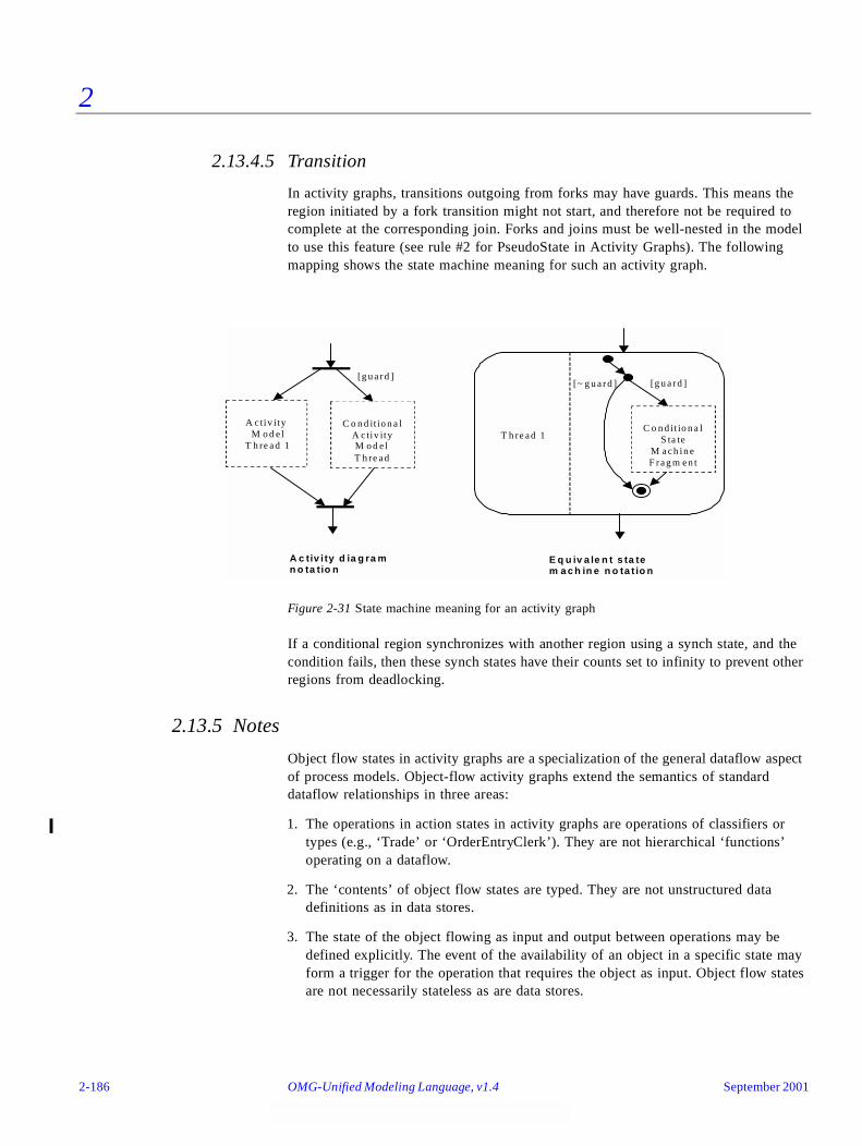
2
2.13.4.5 Transition
In activity graphs, transitions outgoing from forks may have guards. This means the region initiated by a fork transition might not start, and therefore not be required to complete at the corresponding join. Forks and joins must be well-nested in the model to use this feature (see rule #2 for PseudoState in Activity Graphs). The following mapping shows the state machine meaning for such an activity graph.
Figure 2-31 State machine meaning for an activity graph
If a conditional region synchronizes with another region using a synch state, and the condition fails, then these synch states have their counts set to infinity to prevent other regions from deadlocking.
2.13.5 Notes
Object flow states in activity graphs are a specialization of the general dataflow aspect of process models. Object-flow activity graphs extend the semantics of standard dataflow relationships in three areas:
1. The operations in action states in activity graphs are operations of classifiers or types (e.g., ‘Trade’ or ‘OrderEntryClerk’). They are not hierarchical ‘functions’ operating on a dataflow.
2. The ‘contents’ of object flow states are typed. They are not unstructured data definitions as in data stores.
3. The state of the object flowing as input and output between operations may be defined explicitly. The event of the availability of an object in a specific state may form a trigger for the operation that requires the object as input. Object flow states are not necessarily stateless as are data stores.
[g u a r d ]
C o n d it io n a lA c tiv ityM o d e lT h re a d
A c tiv ityM o d e l
T h re a d 1
[g u a r d ][~ g u a r d ]
C o n d it io n a lS ta te
M a c h in eF r a g m e n t
A c tiv i ty d ia g ra mn o ta tio n
E q u iv a le n t s ta tem a c h in e n o ta t io n
T h re a d 1
2-186 OMG-Unified Modeling Language, v1.4 September 2001
2
Part 4 - General MechanismsThis section defines the mechanisms of general applicability to models. This version of UML contains one general mechanisms package, Model Management. The Model Management package specifies how model elements are organized into models, packages, subsystems, and UML profiles.
2.14 Model Management
2.14.1 Overview
The Model Management package is dependent on the Foundation package. It defines Model, Package, and Subsystem, which all serve as grouping units for other ModelElements.
Models are used to capture different views of a physical system. Packages are used within a Model to group ModelElements. A Subsystem represents a behavioral unit in the physical system. UML Profiles are packages dedicated to group UML extensions.
In this section it is necessary to clearly distinguish between the physical system being modeled; that is, the subject of the model and the model element that represent the physical system in the model. For this reason, we consistently use the term physical system when we want to indicate the former, and the term (top-level) subsystem when we want to indicate the latter. An example of a physical system is a credit card service, which includes software, hardware, and wetware (people). The UML model for this physical system might consist of a top-level subsystem called CreditCardService, which is decomposed into subsystems for Authorization, Credit, and Billing. An analogy with the construction of houses would be that the house would correspond to the physical system, while a blueprint would correspond to a model, and an element used in a blueprint would correspond to a model element.
The following sections describe the abstract syntax, well-formedness rules, and semantics of the Model Management package.
2.14.2 Abstract Syntax
The abstract syntax for the Model Management package is expressed in graphic notation in Figure 2-32.
September 2001 OMG-UML , v1.4 Model Management 2-187
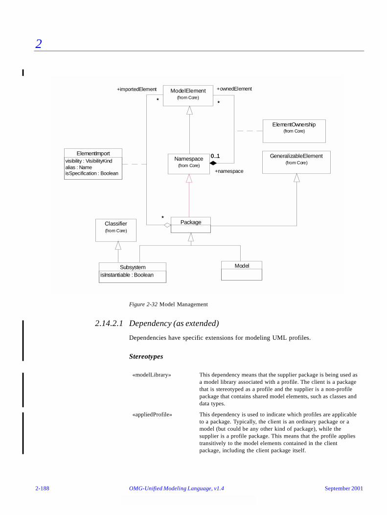
2
Figure 2-32 Model Management
2.14.2.1 Dependency (as extended)
Dependencies have specific extensions for modeling UML profiles.
Stereotypes
«modelLibrary» This dependency means that the supplier package is being used as a model library associated with a profile. The client is a package that is stereotyped as a profile and the supplier is a non-profile package that contains shared model elements, such as classes and data types.
«appliedProfile» This dependency is used to indicate which profiles are applicable to a package. Typically, the client is an ordinary package or a model (but could be any other kind of package), while the supplier is a profile package. This means that the profile applies transitively to the model elements contained in the client package, including the client package itself.
ElementImportvisibility : VisibilityKindalias : NameisSpecification : Boolean
GeneralizableElement(from Core)
SubsystemisInstantiable : Boolean
Model
ElementOwnership(from Core)
Namespace(from Core)
Package
ModelElement(from Core)
*
0..1
+ownedElement
*
+namespace
0..1
*
*
*
+importedElement
*
Classifier(from Core)
2-188 OMG-Unified Modeling Language, v1.4 September 2001
2
2.14.2.2 ElementImport
An element import defines the visibility and alias of a model element included in the namespace within a package, as a result of the package importing another package.
In the metamodel an ElementImport reifies the relationship between a Package and an imported ModelElement. It allows redefinition of the name and the visibility for the imported ModelElement; that is, the ModelElement may be given another name (an alias) and/or a new visibility to be used within the importing Package. The default is no alias (the original name will be used) and private visibility relative to the importing Package.
Attributes
2.14.2.3 Model
A model captures a view of a physical system. It is an abstraction of the physical system, with a certain purpose. This purpose determines what is to be included in the model and what is irrelevant. Thus the model completely describes those aspects of the physical system that are relevant to the purpose of the model, at the appropriate level of detail.
In the metamodel, Model is a subclass of Package. It contains a containment hierarchy of ModelElements that together describe the physical system. A Model also contains a set of ModelElements that represents the environment of the system, typically Actors, together with their interrelationships, such as Dependencies, Generalizations, and Constraints.
Different Models can be defined for the same physical system, where each model represents a view of the physical system defined by its purpose and abstraction level (for example, an analysis model, a design model, an implementation model). Typically different models are complementary and defined from the perspectives (viewpoints) of different system stakeholders. For example, a use-case model may be defined from the viewpoint of a business analyst stakeholder. Each Model is a complete description of the physical system. When Models are nested, the container Model represents the comprehensive view of the physical system given by the different views defined by the contained Models.
alias The alias defines a local name of the imported ModelElement, to be used within the Package.
isSpecification Specifies whether the ownedElement is part of the specification for the containing namespace (in cases where specification is distinguished from the realization). Otherwise the ownedElement is part of the realization. In cases in which the distinction is not made, the value is false by default.
visibility An imported ModelElement is either public, protected, or private relative to the importing Package.
September 2001 OMG-UML , v1.4 Model Management 2-189

2
Stereotypes
2.14.2.4 Package
A package is a grouping of model elements.
In the metamodel Package is a subclass of Namespace and GeneralizableElement. A Package contains ModelElements like Packages, Classifiers, and Associations. A Package may also contain Constraints and Dependencies between ModelElements of the Package.
Each ModelElement of a Package has a visibility relative to the Package stating if the ModelElement is available to ModelElements in other Packages with a Permission («access» or «import») or Generalization relationship to the Package. An «access» or «import» Permission from one Package to another allows public ModelElements in the target Package to be referenced by ModelElements in the source Package. They differ in that all public ModelElements in imported Packages are added to the Namespace within the importing Package, whereas the Namespace within an accessing Package is not affected at all. The ModelElements available in a Package are those in the contents of the Namespace within the Package, which consists of owned and imported ModelElements, together with public ModelElements in accessed Packages.
Associations
«systemModel» A systemModel is a stereotyped model that contains a collection of models of the same physical system. A systemModel also contains all relationships and constraints between model elements contained in different models.
«metamodel» A metamodel is a stereotyped model denoting that the model is an abstraction of another model; that is, it is a model of a model. Hence, if M2 is a model of the model M1, then M2 is a metamodel of M1. It follows then that classes in M1 are instances of metaclasses in M2. The stereotype can be recursively applied, as in the case of a 4-layer metamodel architecture.
importedElement The namespace defined by a package is extended by model elements in other, imported packages.
2-190 OMG-Unified Modeling Language, v1.4 September 2001
2
Stereotypes
Tag Definitions
«facade» A facade is a stereotyped package that contains references to model elements owned by another package. It is used to provide a ‘public view’ of some of the contents of a package. A facade does not contain any model elements of its own.
«framework» A framework is a stereotyped package that contains model elements that specify a reusable architecture for all or part of a system. Frameworks typically include classes, patterns, or templates. When frameworks are specialized for an application domain, they are sometimes referred to as application frameworks.
«modelLibrary» A model library is a stereotyped package that contains model elements that are intended to be reused by other packages. A model library differs from a profile in that a model library does not extend the metamodel using stereotypes and tagged definitions. A model library is analogous to a class library in some programming languages.
«profile» A profile is a stereotyped package that contains model elements that have been customized for a specific domain or purpose using extension mechanisms, such as stereotypes, tagged definitions, and constraints. A profile may also specify model libraries on which it depends and the metamodel subset that it extends. (The latter is specified via an applicableSubset tag definition.)
«stub» A stub is a stereotyped package that represents only the public parts of another package.
«topLevel» TopLevel is a stereotyped package that denotes the highest level package in a containment hierarchy. The topLevel stereotype defines the outer limit for looking up names, as namespaces “see” outwards. A topLevel subsystem is the top of a subsystem containment hierarchy; that is, it is the model element that represents the boundary of the entire physical system being modeled.
{applicableSubset} This tag definition, which only applies to profile packages, lists the metaelements that are used by the associated profile. The value associated with this tag definition is a set of strings, where each string represents the name of an applicable metaelement.
Note that the use of applicable subset does not necessarily exclude the use of any metaelements, but clearly identifies which ones are referenced from the associated profile. Further note that the tag definition applies only to the immediately associated profile. If a profile combines several other profiles using import or generalizations, the applicable subset only applies to the immediately associated profile. The absence of an applicable subset tag definition means that the whole UML metamodel is applicable.
September 2001 OMG-UML , v1.4 Model Management 2-191
2
2.14.2.5 Subsystem
A subsystem is a grouping of model elements that represents a behavioral unit in a physical system. A subsystem offers interfaces and has operations. In addition, the model elements of a subsystem are partitioned into specification and realization elements, where the former, together with the operations of the subsystem, are realized by the latter.
In the metamodel, Subsystem is a subclass of both Package and Classifier. As such it may have a set of Features, which are constrained to be Operations and Receptions, and Associations.
The contents of a Subsystem are divided into two subsets: specification elements and realization elements. The former subset provides, together with the Operations of the Subsystem, a specification of the behavior contained in the Subsystem, while the ModelElements in the latter subset jointly provide a realization of the specification. Any kind of ModelElement can be a specification element or a realization element. The relationships between the specification elements and the realization elements can be defined in different ways (for example, with Collaborations or «realize» dependencies).
Attributes
2.14.3 Well-Formedness Rules
The following well-formedness rules apply to the Model Management package.
2.14.3.1 ElementImport
No extra well-formedness rules.
2.14.3.2 Model
No extra well-formedness rules.
2.14.3.3 Package
[1] No imported element (excluding Association) may have the same name or alias as anyelement owned by the Package or one of its supertypes.
self.allImportedElements->reject( re |
re.oclIsKindOf(Association) )->forAll( re |
(re.elementImport.alias <> ’’ implies
not (self.allContents - self.allImportedElements)->
isInstantiable States whether a Subsystem is instantiable or not. If false, the Subsystem represents a unique part of the physical system; otherwise, there may be several system parts with the same definition.
2-192 OMG-Unified Modeling Language, v1.4 September 2001

2
reject( ve |
ve.oclIsKindOf (Association) )->exists ( ve |
ve.name = re.elementImport.alias))
and
(re.elementImport.alias = ’’ implies
not (self.allContents - self.allImportedElements)->
reject ( ve |
ve.oclIsKindOf (Association) )->exists ( ve |
ve.name = re.name) ) )
[2] Imported elements (excluding Association) may not have the same name or alias.
self.allImportedElements->reject( re |
not re.oclIsKindOf (Association) )->forAll( r1, r2 |
(r1.elementImport.alias <> ’’ and
r2.elementImport.alias <> ’’ and
r1.elementImport.alias = r2.elementImport.alias
implies r1 = r2)
and
(r1.elementImport.alias = ’’ and
r2.elementImport.alias = ’’ and
r1.name = r2.name implies r1 = r2)
and
(r1.elementImport.alias <> ’’ and
r2.elementImport.alias = ’’ implies
r1.elementImport.alias <> r2.name))
[3] No imported element (Association) may have the same name or alias combined with thesame set of associated Classifiers as any Association owned by the Package or one of itssupertypes.
self.allImportedElements->select( re |
re.oclIsKindOf(Association) )->forAll( re |
(re.elementImport.alias <> ’’ implies
not (self.allContents - self.allImportedElements)->
select( ve |
ve.oclIsKindOf(Association) )->exists(
ve : Association |
ve.name = re.elementImport.alias
and
ve.connection->size = re.connection->size and
Sequence {1..re.connection->size}->forAll( i |
re.connection->at(i).participant =
ve.connection->at(i).participant ) ) )
September 2001 OMG-UML , v1.4 Model Management 2-193
2
and
(re.elementImport.alias = ’’ implies
not (self.allContents - self.allImportedElements)->
select( ve |
not ve.oclIsKindOf(Association) )->exists( ve :
Association |
ve.name = re.name
and
ve.connection->size = re.connection->size and
Sequence {1..re.connection->size}->forAll( i |
re.connection->at(i).participant =
ve.connection->at(i).participant ) ) ) )
[4] Imported elements (Association) may not have the same name or alias combined with thesame set of associated Classifiers.
self.allImportedElements->select ( re |
re.oclIsKindOf (Association) )->forAll ( r1, r2 : Association |
(r1.connection->size = r2.connection->size and
Sequence {1..r1.connection->size}->forAll ( i |
r1.connection->at (i).participant =
r2.connection->at (i).participant and
r1.elementImport.alias <> ’’ and
r2.elementImport.alias <> ’’ and
r1.elementImport.alias = r2.elementImport.alias
implies r1 = r2))
and
(r1.connection->size = r2.connection->size and
Sequence {1..r1.connection->size}->forAll ( i |
r1.connection->at (i).participant =
r2.connection->at (i).participant and
r1.elementImport.alias = ’’ and
r2.elementImport.alias = ’’ and
r1.name = r2.name
implies r1 = r2))
and
(r1.connection->size = r2.connection->size and
Sequence {1..r1.connection->size}->forAll ( i |
r1.connection->at (i).participant =
r2.connection->at (i).participant and
r1.elementImport.alias <> ’’ and
r2.elementImport.alias = ’’
2-194 OMG-Unified Modeling Language, v1.4 September 2001
2
implies r1.elementImport.alias <> r2.name)))
Additional Operations
[1] The operation contents results in a Set containing the ModelElements owned by orimported by the Package.
contents : Set(ModelElement)
contents = self.ownedElement->union(self.importedElement)
[2] The operation allImportedElements results in a Set containing the ModelElementsimported by the Package or one of its parents.
allImportedElements : Set(ModelElement)
allImportedElements = self.importedElement->union(
self.parent.oclAsType(Package).allImportedElements->select( re |
re.elementImport.visibility = #public or
re.elementImport.visibility = #protected))
[3] The operation allContents results in a Set containing the ModelElements owned by orimported by the Package or one of its ancestors.
allContents : Set(ModelElement);
allContents = self.contents->union(
self.parent.allContents->select(e |
e.elementOwnership.visibility = #public or
e.elementOwnership.visibility = #protected))
2.14.3.4 Profile
[1] The base classes of all stereotypes in a profile must be part of the applicable subset of thisprofile.
self.applicableSubset->includesAll(self.stereotypes->collect(baseClass))
[2] A profile package can only contain tag definitions, stereotypes, constraints and data types.
self.contents->forAll(e | e.oclIsKindOf(Stereotype) ore.oclIsKindOf(Constraint) or e.oclIsKindOf(TagDefinition) or e.oclIsKindOf (DataType))
2.14.3.5 Subsystem
[1] For each Operation in an Interface offered by a Subsystem, the Subsystem itself or at leastone contained specification element must have a matching Operation.
self.specification.allOperations->forAll(interOp |
self.allOperations->union
(self.allSpecificationElements->select(specEl|
specEl.oclIsKindOf(Classifier))->forAll(c|
September 2001 OMG-UML , v1.4 Model Management 2-195
2
c.allOperations))->exists
( op | op.hasSameSignature(interOp) ) )
[1] For each Reception in an Interface offered by a Subsystem, the Subsystem itself or at leastone contained specification element must have a matching Reception.
let allReceptions : set(Reception) = self.allFeatures->select(f |
f.oclIsKindOf(Reception)) in
self.specification.allReceptions->forAll(interRec |
self.allReceptions->union
(self.allSpecificationElements->select(specEl|
specEl.oclIsKindOf(Classifier))->forAll(c|
c.allReceptions))->exists
( rec | rec.hasSameSignature(interRec) ) )
[3] The Features of a Subsystem may only be Operations or Receptions.
self.feature->forAll(f | f.oclIsKindOf(Operation) or
f.oclIsKindOf(Reception))
[4] A Subsystem may only own or reference Packages, Classes, DataTypes, Interfaces,UseCases, Actors, Subsystems, Signals, Associations, Generalizations, Dependencies,Constraints, Collaborations, StateMachines, and Stereotypes.
self.contents->forAll ( c |
c.oclIsKindOf(Package) or
c.oclIsKindOf(Class) or
c.oclIsKindOf(DataType) or
c.oclIsKindOf(Interface) or
c.oclIsKindOf(UseCase) or
c.oclIsKindOf(Actor) or
c.oclIsKindOf(Subsystem) or
c.oclIsKindOf(Signal) or
c.oclIsKindOf(Association) or
c.oclIsKindOf(Generalization) or
c.oclIsKindOf(Dependency) or
c.oclIsKindOf(Constraint) or
c.oclIsKindOf(Collaboration) or
c.oclIsKindOf(StateMachine) or
c.oclIsKindOf(Stereotype) )
Additional Operations
[1] The operation allSpecificationElements results in a Set containing the Model Elementsspecifying the behavior of the Subsystem.
allSpecificationElements : Set(ModelElement)
allSpecificationElements = self.allContents->select(c | c.elementOwnership.isSpecification )
2-196 OMG-Unified Modeling Language, v1.4 September 2001
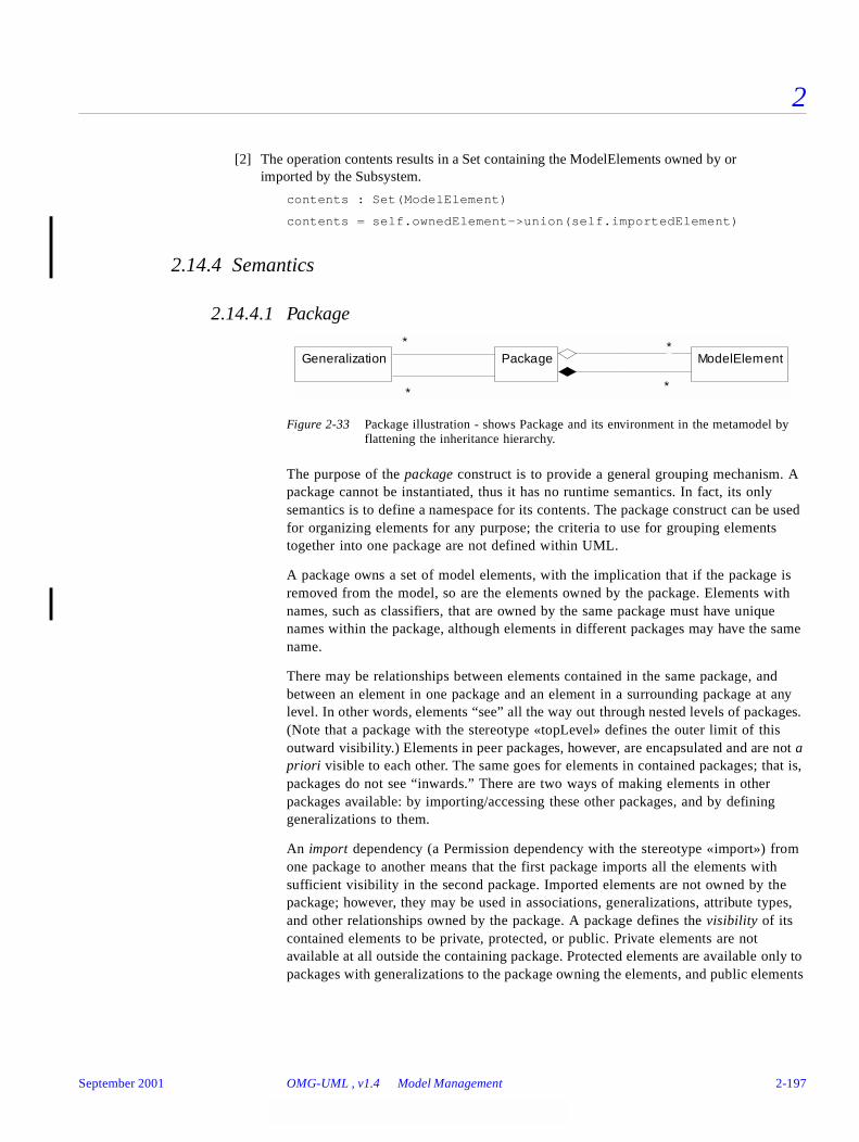
2
[2] The operation contents results in a Set containing the ModelElements owned by orimported by the Subsystem.
contents : Set(ModelElement)
contents = self.ownedElement->union(self.importedElement)
2.14.4 Semantics
2.14.4.1 Package
Figure 2-33 Package illustration - shows Package and its environment in the metamodel byflattening the inheritance hierarchy.
The purpose of the package construct is to provide a general grouping mechanism. A package cannot be instantiated, thus it has no runtime semantics. In fact, its only semantics is to define a namespace for its contents. The package construct can be used for organizing elements for any purpose; the criteria to use for grouping elements together into one package are not defined within UML.
A package owns a set of model elements, with the implication that if the package is removed from the model, so are the elements owned by the package. Elements with names, such as classifiers, that are owned by the same package must have unique names within the package, although elements in different packages may have the same name.
There may be relationships between elements contained in the same package, and between an element in one package and an element in a surrounding package at any level. In other words, elements “see” all the way out through nested levels of packages. (Note that a package with the stereotype «topLevel» defines the outer limit of this outward visibility.) Elements in peer packages, however, are encapsulated and are not a priori visible to each other. The same goes for elements in contained packages; that is, packages do not see “inwards.” There are two ways of making elements in other packages available: by importing/accessing these other packages, and by defining generalizations to them.
An import dependency (a Permission dependency with the stereotype «import») from one package to another means that the first package imports all the elements with sufficient visibility in the second package. Imported elements are not owned by the package; however, they may be used in associations, generalizations, attribute types, and other relationships owned by the package. A package defines the visibility of its contained elements to be private, protected, or public. Private elements are not available at all outside the containing package. Protected elements are available only to packages with generalizations to the package owning the elements, and public elements
*
*ModelElement
*Package
*
*
*
Generalization*
*
September 2001 OMG-UML , v1.4 Model Management 2-197
2
are available also to importing and accessing packages. Note that the visibility mechanism does not restrict the availability of an element to peer elements in the same package.
When an element is imported by a package it extends the namespace of that package. It is possible to give an imported element an alias to avoid name conflicts with the names of the other elements in the namespace, including other imported elements. The alias will then be the name of that element in the namespace; the element will not appear under both the alias and its original name. An imported element is by default private to the importing package. It may, however, be given a more permissive visibility relative to the importing package; that is, the local visibility may be defined as protected or public.
A package with an import dependency to another package imports all the public contents of the namespace defined by the supplier package, including elements of packages imported by the supplier package that are given public visibility in the supplier.
The access dependency (a Permission dependency with the stereotype «access») is similar to the import dependency in that it makes elements in the supplier package available to the client package. However, in this case no elements in the supplier package are included in the namespace of the client. They are simply referred to by their full pathname when referenced in the accessing package. Clearly, they are not visible to packages in turn accessing or importing this package.
A package can have generalizations to other packages. This means that the public and protected elements owned or imported by a package are also available to its children, and can be used in the same way as any element owned or imported by the children themselves. Elements made available to another package by the use of a generalization are referred to by the same name in the child as they are in the parent. Moreover, they have the same visibility in the child as they have in the parent package. Relationships between the ancestor package and other model elements are also inherited by the child package.
A package can be used to define a framework, specifying a reusable architecture for all or part of a system. Frameworks may include reusable classes, patterns or templates. When frameworks are specialized for an application domain, they are sometimes referred to as application frameworks.
2.14.4.2 Profile
A profile stereotype of Package contains one or more related extensions of standard UML semantics (refer to Section 2.6, “Extension Mechanisms,” on page 2-74). These are normally intended to customize UML for a particular domain or purpose. Profiles can contain stereotypes, tag definitions, and constraints. They can also contain data types that are used by tag definitions for informally declaring the types of the values that can be associated with tag definitions.
2-198 OMG-Unified Modeling Language, v1.4 September 2001

2
In addition, a profile package can specify a related model library and identify a subset of the UML metamodel that is applicable for the profile. In principle, profiles merely refine the standard semantics of UML by adding further constraints and interpretations that capture domain-specific semantics and modeling patterns. They do not add any new fundamental concepts.
Relationships between profiles
A profile package can have the usual relationships with other packages such as generalization, import, and access. These have the usual semantics. They are useful to profile designers who may want to import elements from one profile into another, or to combine two or more profiles. However, care should be taken to combine these in a consistent way. For example, extensions from different profiles may be incompatible and their respective constraints may contradict each other. In this revision of UML, no formal mechanisms are defined to verify that a combination of two or more profiles is mutually consistent.
Profile generalization
Generalization of profiles is a relationship between a profile and a more general profile. The more specific profile must be fully consistent with the more general profile; that is, it has all the same tag definitions, stereotypes, and constraints, and may add further refinements, which must not contradict its parent. Note that the subset of UML defined as applicable by a profile is not inherited by specializing profiles, whereas relationships to model libraries are.
Access and import dependencies between profiles
Profiles can have access and import dependencies with the usual semantics. This allows elements in one profile to access or use elements in the related profiles. An applied profiles dependency will allow a client package to use all stereotypes and tag definitions accessible by the supplier package. As in all other types of packages, a profile can own other profiles with standard semantics of ownership and accessibility.
Applying a profile to a package
A UML model can be based on a number of different UML profiles. The applicable profiles are identified by specially stereotyped «appliedProfile» dependencies from the UML model package to the appropriate profile packages. This declaration enables the UML model to access the stereotypes and tag definitions of these profiles.
September 2001 OMG-UML , v1.4 Model Management 2-199

2
2.14.4.3 Subsystem
Figure 2-34 Subsystem illustration - shows Subsystem and its environment in the metamodel by flattening the inheritance hierarchy.
The purpose of the subsystem construct is to provide a grouping mechanism for specifying a behavioral unit of a physical system. Apart from defining a namespace for its contents, a subsystem serves as a specification unit for the behavior of its contained model elements.
The contents of a subsystem are defined in the same way as for a package, thus it consists of owned elements and imported elements, with unique names or aliases within the subsystem. The contents of a subsystem are divided into two subsets: 1) specification elements and 2) realization elements. The specification elements, together with the operations and receptions of the subsystem, are used for giving an abstract specification of the behavior offered by the realization elements. The collection of realization elements model the interior of the behavioral unit of the physical system. Consequently, subsystems contained in the realization part represent subordinate subsystems; that is, subsystems at the level below in the containment hierarchy, hence owned by the current subsystem.
The specification of a subsystem thus consists of the specification elements together with the subsystem’s features (operations and receptions). It specifies the behavior performed jointly by instances of classifiers in the realization subset, without revealing anything about the contents of this subset. The specification is typically made in terms of model elements such as use cases and/or operations, although other kinds of model elements like classes, interfaces, constraints, relationships between model elements, state machines may also be used. Use cases are used to specify complete sequences performed by the subsystem; that is, by instances of its contained classifiers interacting with its surroundings. Operations are suitable to represent simpler subsystem services that are used independently of each other; that is, not in any particular order.
A subsystem has no behavior of its own. All behavior defined in the specification of the subsystem is jointly offered by the elements in the realization subset of the contents. In general, since subsystems are classifiers, they can appear anywhere a classifier is expected. It follows that, since the subsystem itself has no behavior of its own, the requirements posed on the subsystem in the context where it occurs are fulfilled by the realization of the subsystem.
The correspondence between the specification and the realization of a subsystem can be specified in several ways, including collaborations and «realize» dependencies. A collaboration specifies how instances of the realization elements cooperate to jointly perform the behavior specified by a use case, an operation, etc. in the subsystem specification; that is, how the higher level of abstraction is transformed into the lower
InterfaceBehavioralFeature
*
*
Generalization*
Subsystem
**
*
ModelElement
**
SubsystemInstance
2-200 OMG-Unified Modeling Language, v1.4 September 2001

2
level of abstraction. A stimulus received by an instance of a use case (higher level of abstraction) corresponds to an instance conforming to one of the classifier roles in the collaboration receiving that stimulus (lower level of abstraction). This instance communicates with other instances conforming to other classifier roles in the collaboration, and together they perform the behavior specified by the use case. All stimuli that can be received and sent by instances of the use cases are also received and sent by the conforming instances, although at a lower level of abstraction. Similarly, application of an operation of the subsystem actually means that a stimulus is sent to a contained instance that performs a method.
There are two ways of communicating with a subsystem, either by sending stimuli to the subsystem itself to be re-directed to the proper recipient inside the subsystem, or by sending stimuli directly to the recipient inside the subsystem. In the first case, an association is defined with the subsystem itself to enable stimuli sending. (In the abstract syntax, this is handled by a single subsystem instance being connected by links corresponding to this association, receiving stimuli sent to the subsystem, and re-directing them to instances within the subsystem instance. Hence the subsystem instance is the “runtime representative” of the subsystem. Note that this subsystem instance still does not perform any of the behavior specified in the subsystem specification.) How stimuli sent to the subsystem are re-directed to internal instances is not defined but left as a semantic variation point.
Communicating with a subsystem by sending stimuli directly to instances within the subsystem requires that the classifiers of these instances are available within the sender’s namespace so that they can be connected by associations. This can be achieved by import or access permissions. Importing and accessing subsystems is done in the same way as with packages, using the visibility property to define whether elements are public, protected, or private to the subsystem. Both the specification part and the realization part of a subsystem may include imported elements.
A subsystem can have generalizations to other subsystems. This means that the public and protected elements in the contents of a subsystem as well as operations and receptions are also available to its heirs. Furthermore, relationships between an ancestor subsystem and other model elements are inherited by specializing subsystems. In a concrete (non-abstract) subsystem all elements in the specification, including elements from ancestors, are completely realized by cooperating realization elements, as specified with, for example, a set of collaborations. This may not be true for abstract subsystems.
A subsystem may offer a set of interfaces. This implies that for each operation defined in an interface, the subsystem offering the interface must have a matching operation, either as a feature of the subsystem itself or of a specification element. The relationship between interface and subsystem is not necessarily one-to-one. Interfaces of a subsystem are usually contained in the same namespace as the subsystem itself, but may also be contained in the specification of the subsystem. In the latter case, elements using these interfaces must have an import or access relationship with the subsystem to gain access to the interfaces.
September 2001 OMG-UML , v1.4 Model Management 2-201
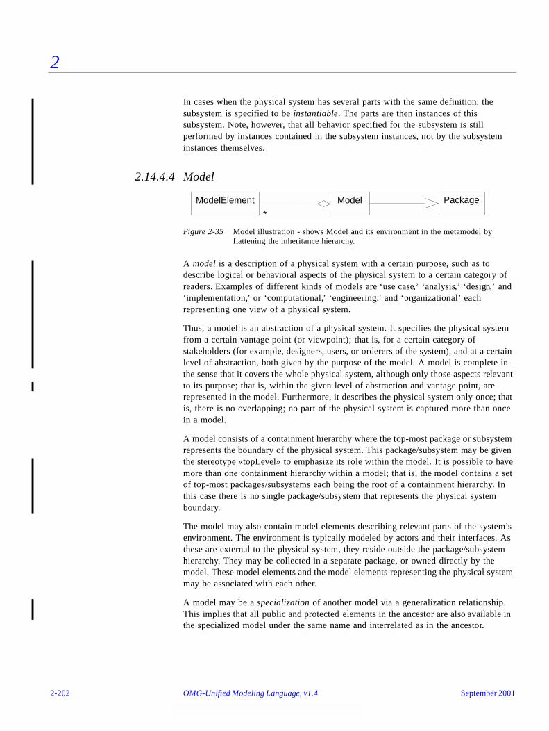
2
In cases when the physical system has several parts with the same definition, the subsystem is specified to be instantiable. The parts are then instances of this subsystem. Note, however, that all behavior specified for the subsystem is still performed by instances contained in the subsystem instances, not by the subsystem instances themselves.
2.14.4.4 Model
Figure 2-35 Model illustration - shows Model and its environment in the metamodel by flattening the inheritance hierarchy.
A model is a description of a physical system with a certain purpose, such as to describe logical or behavioral aspects of the physical system to a certain category of readers. Examples of different kinds of models are ‘use case,’ ‘analysis,’ ‘design,’ and ‘implementation,’ or ‘computational,’ ‘engineering,’ and ‘organizational’ each representing one view of a physical system.
Thus, a model is an abstraction of a physical system. It specifies the physical system from a certain vantage point (or viewpoint); that is, for a certain category of stakeholders (for example, designers, users, or orderers of the system), and at a certain level of abstraction, both given by the purpose of the model. A model is complete in the sense that it covers the whole physical system, although only those aspects relevant to its purpose; that is, within the given level of abstraction and vantage point, are represented in the model. Furthermore, it describes the physical system only once; that is, there is no overlapping; no part of the physical system is captured more than once in a model.
A model consists of a containment hierarchy where the top-most package or subsystem represents the boundary of the physical system. This package/subsystem may be given the stereotype «topLevel» to emphasize its role within the model. It is possible to have more than one containment hierarchy within a model; that is, the model contains a set of top-most packages/subsystems each being the root of a containment hierarchy. In this case there is no single package/subsystem that represents the physical system boundary.
The model may also contain model elements describing relevant parts of the system’s environment. The environment is typically modeled by actors and their interfaces. As these are external to the physical system, they reside outside the package/subsystem hierarchy. They may be collected in a separate package, or owned directly by the model. These model elements and the model elements representing the physical system may be associated with each other.
A model may be a specialization of another model via a generalization relationship. This implies that all public and protected elements in the ancestor are also available in the specialized model under the same name and interrelated as in the ancestor.
PackageModelElement Model
**
2-202 OMG-Unified Modeling Language, v1.4 September 2001
2
A model may import or access another model. The semantics is the same as for packages. However, some of the actors of the supplier model may be internal to the client. This is the case, for example, when the imported model represents a lower layer of the physical system than the client model represents. Then some of the actors of the lower layer model represent the upper layer. The conformance requirement is that there must be classifiers in the client whose instances may play the roles of such actors.
The contents of a model is the transitive closure of its owned model elements, like packages, classifiers, and relationships, together with inherited and imported elements.
There may be relationships between model elements in different models, such as refinement and trace. A trace; that is, an abstraction dependency with the stereotype «trace» indicates that the connected (sets of) model elements represent the same concept. Trace is used for tracing requirements between models, or tracing the impact on other models of a change to a model element in one model. Thus traces are usually non-directional dependencies. Relationships between model elements in different models have no impact on the model elements’ meaning in their containing models because of the self-containment of models. Note, though, that even if inter-model relationships do not express any semantics in relation to the models, they may have semantics in relation to the reader or in deriving model elements as part of the overall development process.
Models may be nested (for example, several models of the same physical system may be collected in a model with the stereotype «systemModel»). The models contained in the «systemModel» all describe the physical system from different viewpoints, the viewpoints not necessarily disjoint. The «systemModel» also contains all inter-model relationships. A «systemModel» constitutes a comprehensive specification of the physical system.
A large physical system may be composed by a set of subordinate physical systems together making up the large physical system. In this case each subordinate physical system is described by its own set of models collected in a separate «systemModel». This is an alternative to having each part of the physical system defined as a subsystem.
2.14.5 Notes
In UML, there are three different ways to model a group of elements contained in another element; by using a package, a subsystem, or a class. Some pragmatics on their use include:
• Packages are used when nothing but a plain grouping of elements is required.
• Subsystems provide grouping suitable for top-down development, since the requirements on the behavior of their contents can be expressed before the realization of this behavior is defined. Furthermore, from a bottom-up perspective, the specification of a subsystem may also be seen as a provider of “high level APIs” of the subsystem.
• Classes are used when the container itself should have instances, so that it is possible to define composite objects.
September 2001 OMG-UML , v1.4 Model Management 2-203
2
As Subsystem and Model both are Packages in the metamodel, all three constructs can be combined arbitrarily to organize a containment hierarchy. For example, a Subsystem may be defined using a set of Models, in which case these Models are contained in the Subsystem. Another example is a set of components defined by Subsystems, collected in a Package defining a reuse library.
It is a tool issue to decide how many of the imported elements must be explicitly referenced by the importing package; that is, how many ElementImport links to actually implement. For example, if all elements have the default visibility (private) and their original names in the importing package, the information can be retrieved directly from the imported package.
If a tool does not support the separation of specification and realization elements for Subsystem, then the value of the isSpecification attribute for ElementOwnership should be false by default. See the Core package, where ElementOwnership is defined, for details.
The issue of how to represent the runtime presence of a Subsystem has been solved by introducing SubsystemInstance, even for a non-instantiable Subsystem. An alternative, less intuitive, solution would be to have the metaclass Subsystem inherit the metaclass Instance, thus getting the desired characteristics.
Because this is a logical model of the UML, distribution or sharing of models between tools is not described.
It is expected that tools will manage presentation elements, in particular diagrams, that are attached to model elements.
2-204 OMG-Unified Modeling Language, v1.4 September 2001
UML Notation Guide 3
This guide describes the notation for the visual representation of the Unified Modeling Language (UML). This notation document contains brief summaries of the semantics of UML constructs, but the UML Semantics chapter must be consulted for full details.
Contents
This chapter contains the following topics.
Topic Page
“Part 1 - Background”
“Introduction” 3-5
Part 2 - Diagram Elements
“Graphs and Their Contents” 3-6
“Drawing Paths” 3-7
“Invisible Hyperlinks and the Role of Tools” 3-7
“Background Information” 3-8
“String” 3-8
“Name” 3-9
“Label” 3-10
“Keywords” 3-11
“Expression” 3-11
“Type-Instance Correspondence” 3-14
Part 3 - Model Management
September 2001 OMG-Unified Modeling Language, v1.4 3-1

3
“Package” 3-16
“Subsystem” 3-19
“Model” 3-24
Part 4 - General Extension Mechanisms
“Constraint and Comment” 3-26
“Element Properties” 3-29
“Stereotypes” 3-31
Part 5 - Static Structure Diagrams
“Class Diagram” 3-34
“Object Diagram” 3-35
“Classifier” 3-35
“Class” 3-35
“Name Compartment” 3-38
“List Compartment” 3-38
“Attribute” 3-41
“Operation” 3-44
“Nested Class Declarations” 3-48
“Type and Implementation Class” 3-49
“Interfaces” 3-50
“Parameterized Class (Template)” 3-52
“Bound Element” 3-54
“Utility” 3-56
“Metaclass” 3-57
“Enumeration” 3-57
“Stereotype Declaration” 3-57
“Powertype” 3-61
“Class Pathnames” 3-62
“Accessing or Importing a Package” 3-63
“Object” 3-64
“Composite Object” 3-67
“Association” 3-68
“Binary Association” 3-68
Topic Page
3-2 OMG-Unified Modeling Language, v1.4 September 2001
3
“Association End” 3-71
“Multiplicity” 3-75
“Qualifier” 3-76
“Association Class” 3-77
“N-ary Association” 3-79
“Composition” 3-81
“Link” 3-84
“Generalization” 3-86
“Dependency” 3-90
“Derived Element” 3-93
“InstanceOf” 3-93
Part 6 - Use Case Diagrams
“Use Case Diagram” 3-94
“Use Case” 3-96
“Actor” 3-97
“Use Case Relationships” 3-97
“Actor Relationships” 3-99
Part 7 - Interaction Diagrams
“Collaboration” 3-101
“Sequence Diagram” 3-102
“Object Lifeline” 3-108
“Activation” 3-110
“Message and Stimulus” 3-111
“Transition Times” 3-114
Part 8 - Collaboration Diagrams
“Collaboration Diagram” 3-115
“Pattern Structure” 3-118
“Collaboration Contents” 3-122
“Interactions” 3-124
“Collaboration Roles” 3-125
“Multiobject” 3-128
“Active object” 3-129
Topic Page
September 2001 OMG-UML , v1.4 3-3
3
“Message and Stimulus” 3-111
“Creation/Destruction Markers” 3-135
Part 9 - Statechart Diagrams
“Statechart Diagram” 3-137
“State” 3-138
“Composite States” 3-141
“Events” 3-143
“Simple Transitions” 3-146
“Transitions to and from Concurrent States” 3-147
“Transitions to and from Composite States” 3-148
“Factored Transition Paths” 3-151
“Submachine States” 3-153
“Synch States” 3-155
Part 10 - Activity Diagrams
“Activity Diagram” 3-156
“Action State” 3-159
“Subactivity state” 3-160
“Decisions” 3-160
“Call States” 3-162
“Swimlanes” 3-162
“Action-Object Flow Relationships” 3-164
“Control Icons” 3-166
“Synch States” 3-169
“Dynamic Invocation” 3-169
“Conditional Forks” 3-170
Part 11 - Implementation Diagrams
“Component Diagram” 3-170
“Deployment Diagram” 3-172
“Node” 3-174
“Component” 3-176
Topic Page
3-4 OMG-Unified Modeling Language, v1.4 September 2001
3
Part 1 - Background
3.1 Introduction
This chapter is arranged in parts according to semantic concepts subdivided by diagram types. Within each diagram type, model elements that are found on that diagram and their representation are listed. Note that many model elements are usable in more than one diagram. An attempt has been made to place each description where it is used the most, but be aware that the document involves implicit cross-references and that elements may be useful in places other than the section in which they are described. Be aware also that the document is nonlinear: there are forward references in it. It is not intended to be a teaching document that can be read linearly, but a reference document organized by affinity of concept.
Each part of this chapter is divided into sections, roughly corresponding to important model elements and notational constructs. Note that some of these constructs are used within other constructs; do not be misled by the flattened structure of the chapter. Within each section the following subsections may be found:
• Semantics: Brief summary of semantics. For a fuller explanation and discussion of fine points, see the UML Semantics chapter in this specification.
• Notation: Explains the notational representation of the semantic concept (“forward mapping to notation”).
• Presentation options: Describes various options in presenting the model information, such as the ability to suppress or filter information, alternate ways of showing things, and suggestions for alternate ways of presenting information within a tool.
Dynamic tools need the freedom to present information in various ways and the authors do not want to restrict this excessively. In some sense, we are defining the “canonical notation” that printed documents show, rather than the “screen notation.” The ability to extend the notation can lead to unintelligible dialects, so we hope this freedom will be used in intuitive ways. The authors have not sought to eliminate all the ambiguity that some of these presentation options may introduce, because the presence of the underlying model in a dynamic tool serves to easily disambiguate things. Note that a tool is not supposed to pick just one of the presentation options and implement it. Tools should offer users the options of selecting among various presentation options, including some that are not described in this document.
• Style guidelines: Include suggestions for the use of stylistic markers, such as fonts, naming conventions, arrangement of symbols that are not explicitly part of the notation, but that help to make diagrams more readable. These are similar to text indentation rules in C++ or Smalltalk. Not everyone will choose to follow these suggestions, but the use of some consistent guidelines of your own choosing is recommended in any case.
• Example: Shows samples of the notation. String and code examples are given in the following font: This is a string sample.
September 2001 OMG-UML , v1.4 Introduction 3-5

3
• Mapping: Shows the mapping of notation elements to metamodel elements (“reverse mapping from notation”). This indicates how the notation would be represented as semantic information. Note that, in general, diagrams are interpreted in a particular context in which semantic and graphic information is gathered simultaneously. The assumption is that diagrams are constructed by an editing tool that internalizes the model as the diagram is constructed. Some semantic constructs have no graphic notation and would be shown to a user within a tool using a form or table.
Part 2 - Diagram Elements
3.2 Graphs and Their Contents
Most UML diagrams and some complex symbols are graphs containing nodes connected by paths. The information is mostly in the topology, not in the size or placement of the symbols (there are some exceptions, such as a sequence diagram with a metric time axis). There are three kinds of visual relationships that are important:
1. connection (usually of lines to 2-d shapes),
2. containment (of symbols by 2-d shapes with boundaries), and
3. visual attachment (one symbol being “near” another one on a diagram).
These visual relationships map into connections of nodes in a graph, the parsed form of the notation.
UML notation is intended to be drawn on 2-dimensional surfaces. Some shapes are 2-dimensional projections of 3-d shapes (such as cubes), but they are still rendered as icons on a 2-dimensional surface. In the near future, true 3-dimensional layout and navigation may be possible on desktop machines; however, it is not currently practical.
There are basically four kinds of graphical constructs that are used in UML notation:
1. Icons - An icon is a graphical figure of a fixed size and shape. It does not expand to hold contents. Icons may appear within area symbols, as terminators on paths or as standalone symbols that may or may not be connected to paths.
2. 2-d Symbols - Two-dimensional symbols have variable height and width and they can expand to hold other things, such as lists of strings or other symbols. Many of them are divided into compartments of similar or different kinds. Paths are connected to two-dimensional symbols by terminating the path on the boundary of the symbol. Dragging or deleting a 2-d symbol affects its contents and any paths connected to it.
3. Paths - Sequences of line segments whose endpoints are attached. Conceptually a path is a single topological entity, although its segments may be manipulated graphically. A segment may not exist apart from its path. Paths are always attached to other graphic symbols at both ends (no dangling lines). Paths may have terminators; that is, icons that appear in some sequence on the end of the path and that qualify the meaning of the path symbol.
3-6 OMG-Unified Modeling Language, v1.4 September 2001
3
4. Strings - Present various kinds of information in an “unparsed” form. UML assumes that each usage of a string in the notation has a syntax by which it can be parsed into underlying model information. For example, syntaxes are given for attributes, operations, and transitions. These syntaxes are subject to extension by tools as a presentation option. Strings may exist as singular elements of symbols or compartments of symbols, as elements in lists (in which case the position in the list conveys information), as labels attached to symbols or paths, or as stand-alone elements on a diagram.
3.3 Drawing Paths
A path consists of a series of line segments whose endpoints coincide. The entire path is a single topological unit. Line segments may be orthogonal lines, oblique lines, or curved lines. Certain common styles of drawing lines exist: all orthogonal lines, or all straight lines, or curves only for bevels. The line style can be regarded as a tool restriction on default line input. When line segments cross, it may be difficult to know which visual piece goes with which other piece; therefore, a crossing may optionally be shown with a small semicircular jog by one of the segments to indicate that the paths do not intersect or connect (as in an electrical circuit diagram).
In some relationships (such as aggregation and generalization) several paths of the same kind may connect to a single symbol. In some circumstances (described for the particular relationship) the line segments connected to the symbol can be combined into a single line segment, so that the path from that symbol branches into several paths in a kind of tree. This is purely a graphical presentation option; conceptually the individual paths are distinct. This presentation option may not be used when the modeling information on the segments to be combined is not identical.
3.4 Invisible Hyperlinks and the Role of Tools
A notation on a piece of paper contains no hidden information. A notation on a computer screen may contain additional invisible hyperlinks that are not apparent in a static view, but that can be invoked dynamically to access some other piece of information, either in a graphical view or in a textual table. Such dynamic links are as much a part of a dynamic notation as the visible information, but this guide does not prescribe their form. We regard them as a tool responsibility. This document attempts to define a static notation for the UML, with the understanding that some useful and interesting information may show up poorly or not at all in such a view. On the other hand, we do not know enough to specify the behavior of all dynamic tools, nor do we want to stifle innovation in new forms of dynamic presentation. Eventually some of the dynamic notations may become well enough established to standardize them, but we do not feel that we should do so now.
September 2001 OMG-UML , v1.4 Drawing Paths 3-7
3
3.5 Background Information
3.5.1 Presentation Options
Each appearance of a symbol for a class on a diagram or on different diagrams may have its own presentation choices. For example, one symbol for a class may show the attributes and operations and another symbol for the same class may suppress them. Tools may provide style sheets attached either to individual symbols or to entire diagrams. The style sheets would specify the presentation choices. (Style sheets would be applicable to most kinds of symbols, not just classes.)
Not all modeling information is presented most usefully in a graphical notation. Some information is best presented in a textual or tabular format. For example, much detailed programming information is best presented as text lists. The UML does not assume that all of the information in a model will be expressed as diagrams; some of it may only be available as tables. This document does not attempt to prescribe the format of such tables or of the forms that are used to access them, because the underlying information is adequately described in the UML metamodel and the responsibility for presenting tabular information is a tool responsibility. It is assumed that hidden links may exist from graphical items to tabular items.
3.6 String
A string is a sequence of characters in some suitable character set used to display information about the model. Character sets may include non-Roman alphabets and characters.
3.6.1 Semantics
Diagram strings normally map underlying model strings that store or encode information about the model, although some strings may exist purely on the diagrams. UML assumes that the underlying character set is sufficient for representing multibyte characters in various human languages; in particular, the traditional 8-bit ASCII character set is insufficient. It is assumed that the tool and the computer manipulate and store strings correctly, including escape conventions for special characters, and this document will assume that arbitrary strings can be used without further fuss.
3.6.2 Notation
A string is displayed as a text string graphic. Normal printable characters should be displayed directly. The display of nonprintable characters is unspecified and platform-dependent. Depending on purpose, a string might be shown as a single-line entity or as a paragraph with automatic line breaks.
Typeface and font size are graphic markers that are normally independent of the string itself. They may code for various model properties, some of which are suggested in this document and some of which are left open for the tool or the user.
3-8 OMG-Unified Modeling Language, v1.4 September 2001
3
3.6.3 Presentation Options
Tools may present long strings in various ways, such as truncation to a fixed size, automatic wrapping, or insertion of scroll bars. It is assumed that there is a way to obtain the full string dynamically.
3.6.4 Examples
BankAccount
integrate (f: Function, from: Real, to: Real)
{ author = “Joe Smith”, deadline = 31-March-1997, status = analysis }
The purpose of the shuffle operation is nominally to put the cards into a random configuration. However, to more closely capture the behavior of physical decks, in which blocks of cards may stick together during several riffles, the operation is actually simulated by cutting the deck and merging the cards with an imperfect merge.
3.6.5 Mapping
A graphic string maps into a string within a model element. The mapping depends on context. In some circumstances, the visual string is parsed into multiple model elements. For example, an operation signature is parsed into its various fields. Further details are given with each kind of symbol.
3.7 Name
3.7.1 Semantics
A name is a string that is used to identify a model element uniquely within some scope. A pathname is used to find a model element starting from the root of the system (or from some other point). A name is a selector (qualifier) within some scope—the scope is made clear in this document for each element that can be named.
A pathname is a series of names linked together by a delimiter (such as ‘::’). There are various kinds of pathnames described in this document, each in its proper place and with its particular delimiter.
3.7.2 Notation
A name is displayed as a text string graphic. Normally a name is displayed on a single line and will not contain nonprintable characters. Tools and languages may impose reasonable limits on the length of strings and the character set they use for names, possibly more restrictive than those for arbitrary strings, such as comments.
September 2001 OMG-UML , v1.4 Name 3-9
3
3.7.3 Example
Names:
BankAccount
integrate
controller
abstract
this_is_a_very_long_name_with_underscores
Pathname:
MathPak::Matrices::BandedMatrix
3.7.4 Mapping
Maps to the name of a model element. The mapping depends on context, as with String. Further details are given with the particular element.
3.8 Label
A label is a string that is attached to a graphic symbol.
3.8.1 Semantics
A label is a term for a particular use of a string on a diagram. It is purely a notational term.
3.8.2 Notation
A label is a string that is attached graphically to another symbol on a diagram. Visually the attachment normally is by containment of the string (in a closed region) or by placing the string near the symbol. Sometimes the string is placed in a definite position (such as below a symbol) but most of the time the statement is that the string must be “near” the symbol. A tool maintains an explicit internal graphic linking between a label and a graphic symbol, so that the label drags with the symbol, but the final appearance of the diagram is a matter of aesthetic judgment and should be made so that there is no confusion about which symbol a label is attached to. Although the attachment may not be obvious from a visual inspection of a diagram, the attachment is clear and unambiguous at the graphic level (and poses no ambiguity in the semantic mapping).
3-10 OMG-Unified Modeling Language, v1.4 September 2001
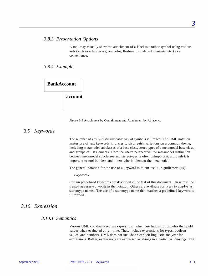
3
3.8.3 Presentation Options
A tool may visually show the attachment of a label to another symbol using various aids (such as a line in a given color, flashing of matched elements, etc.) as a convenience.
3.8.4 Example
Figure 3-1 Attachment by Containment and Attachment by Adjacency
3.9 Keywords
The number of easily-distinguishable visual symbols is limited. The UML notation makes use of text keywords in places to distinguish variations on a common theme, including metamodel subclasses of a base class, stereotypes of a metamodel base class, and groups of list elements. From the user’s perspective, the metamodel distinction between metamodel subclasses and stereotypes is often unimportant, although it is important to tool builders and others who implement the metamodel.
The general notation for the use of a keyword is to enclose it in guillemets («»):
«keyword»
Certain predefined keywords are described in the text of this document. These must be treated as reserved words in the notation. Others are available for users to employ as stereotype names. The use of a stereotype name that matches a predefined keyword is ill formed.
3.10 Expression
3.10.1 Semantics
Various UML constructs require expressions, which are linguistic formulas that yield values when evaluated at run-time. These include expressions for types, boolean values, and numbers. UML does not include an explicit linguistic analyzer for expressions. Rather, expressions are expressed as strings in a particular language. The
BankAccount
account
September 2001 OMG-UML , v1.4 Keywords 3-11
3
OCL constraint language is used within the UML semantic definition and may also be used at the user level; other languages (such as programming languages) may also be used.
UML avoids specifying the syntax for constructing type expressions because they are so language-dependent. It is assumed that the name of a class or simple data type will map into a simple Classifier reference, but the syntax of complicated language-dependent type expressions, such as C++ function pointers, is the responsibility of the specification language.
3.10.2 Notation
An expression is displayed as a string defined in a particular language. The syntax of the string is the responsibility of a tool and a linguistic analyzer for the language. The assumption is that the analyzer can evaluate strings at run-time to yield values of the appropriate type, or can yield semantic structures to capture the meaning of the expression. For example, a type expression evaluates to a Classifier reference, and a boolean expression evaluates to a true or false value. The language itself is known to a modeling tool but is generally implicit on the diagram, under the assumption that the form of the expression makes its purpose clear.
3.10.3 Examples
BankAccount
BankAccount * (*) (Person*, int)
array [1..20] of reference to range (-1.0..1.0) of Real
[ i > j and self.size > i ]
3.10.4 Mapping
An expression string maps to an Expression element (possibly a particular subclass of Expression, such as ObjectSetExpression or TimeExpression).
3.10.5 OCL Expressions
UML includes a definition of the OCL language, which is used to define constraints within the UML metamodel itself. The OCL language may be supported by tools for user-written expressions as well. Other possible languages include various computer languages as well as plain text (which cannot be parsed by a tool, of course, and is therefore only for human information). The OCL language is defined in the “Object Constraint Language Specification” chapter.
3-12 OMG-Unified Modeling Language, v1.4 September 2001

3
3.10.6 Selected OCL Notation
Syntax for some common navigational expressions are shown below. These forms can be chained together. The leftmost element must be an expression for an object or a set of objects. The expressions are meant to work on sets of values when applicable.
3.10.7 Examples
flight.pilot.training_hours > flight.plane.minimum_hours
company.employees−>select (title = “Manager” and self.reports−>size > 10)
3.11 Note
A note is a graphical symbol containing textual information (possibly including embedded images). It is a notation for rendering various kinds of textual information from the metamodel, such as constraints, comments, method bodies, and tagged values.
3.11.1 Semantics
A note is a notational item. It shows textual information within some semantic element.
3.11.2 Notation
A note is shown as a rectangle with a “bent corner” in the upper right corner. It contains arbitrary text. It appears on a particular diagram and may be attached to zero or more modeling elements by dashed lines.
3.11.3 Presentation Options
A note may have a stereotype.
item ‘.’ selector The selector is the name of an attribute in the item or the name of the target end of a link attached to the item. The result is the value of the attribute or the related object(s). The result is a value or a set of values depending on the multiplicities of the item and the association.
item ‘.’ selector ‘[‘ qualifier-value ‘]’ The selector designates a qualified association that qualifies the item. The qualifier-value is a value for the qualifier attribute. The result is the related object selected by the qualifier. Note that this syntax is applicable to array indexing as a form of qualification.
set ‘->’ ‘select’ ‘(‘ boolean-expression ‘)’ The boolean-expression is written in terms of objects within the set. The result is the subset of objects in the set for which the boolean expression is true.
September 2001 OMG-UML , v1.4 Note 3-13
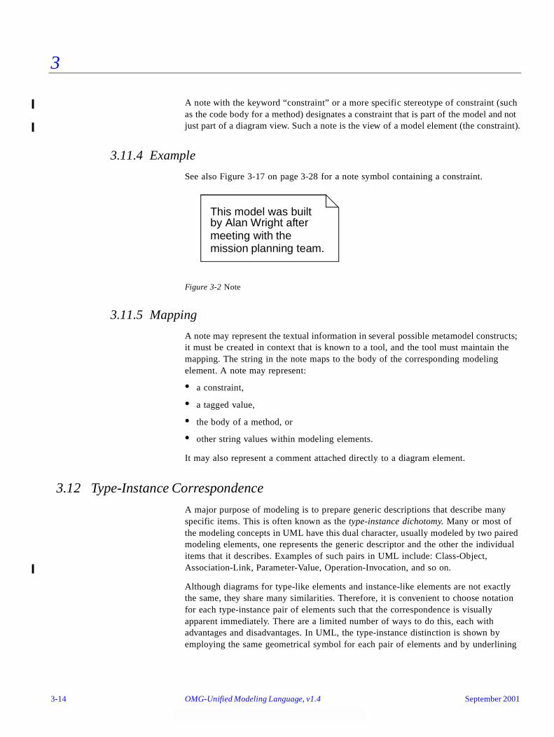
3
A note with the keyword “constraint” or a more specific stereotype of constraint (such as the code body for a method) designates a constraint that is part of the model and not just part of a diagram view. Such a note is the view of a model element (the constraint).
3.11.4 Example
See also Figure 3-17 on page 3-28 for a note symbol containing a constraint.
Figure 3-2 Note
3.11.5 Mapping
A note may represent the textual information in several possible metamodel constructs; it must be created in context that is known to a tool, and the tool must maintain the mapping. The string in the note maps to the body of the corresponding modeling element. A note may represent:
• a constraint,
• a tagged value,
• the body of a method, or
• other string values within modeling elements.
It may also represent a comment attached directly to a diagram element.
3.12 Type-Instance Correspondence
A major purpose of modeling is to prepare generic descriptions that describe many specific items. This is often known as the type-instance dichotomy. Many or most of the modeling concepts in UML have this dual character, usually modeled by two paired modeling elements, one represents the generic descriptor and the other the individual items that it describes. Examples of such pairs in UML include: Class-Object, Association-Link, Parameter-Value, Operation-Invocation, and so on.
Although diagrams for type-like elements and instance-like elements are not exactly the same, they share many similarities. Therefore, it is convenient to choose notation for each type-instance pair of elements such that the correspondence is visually apparent immediately. There are a limited number of ways to do this, each with advantages and disadvantages. In UML, the type-instance distinction is shown by employing the same geometrical symbol for each pair of elements and by underlining
This model was builtby Alan Wright aftermeeting with themission planning team.
3-14 OMG-Unified Modeling Language, v1.4 September 2001
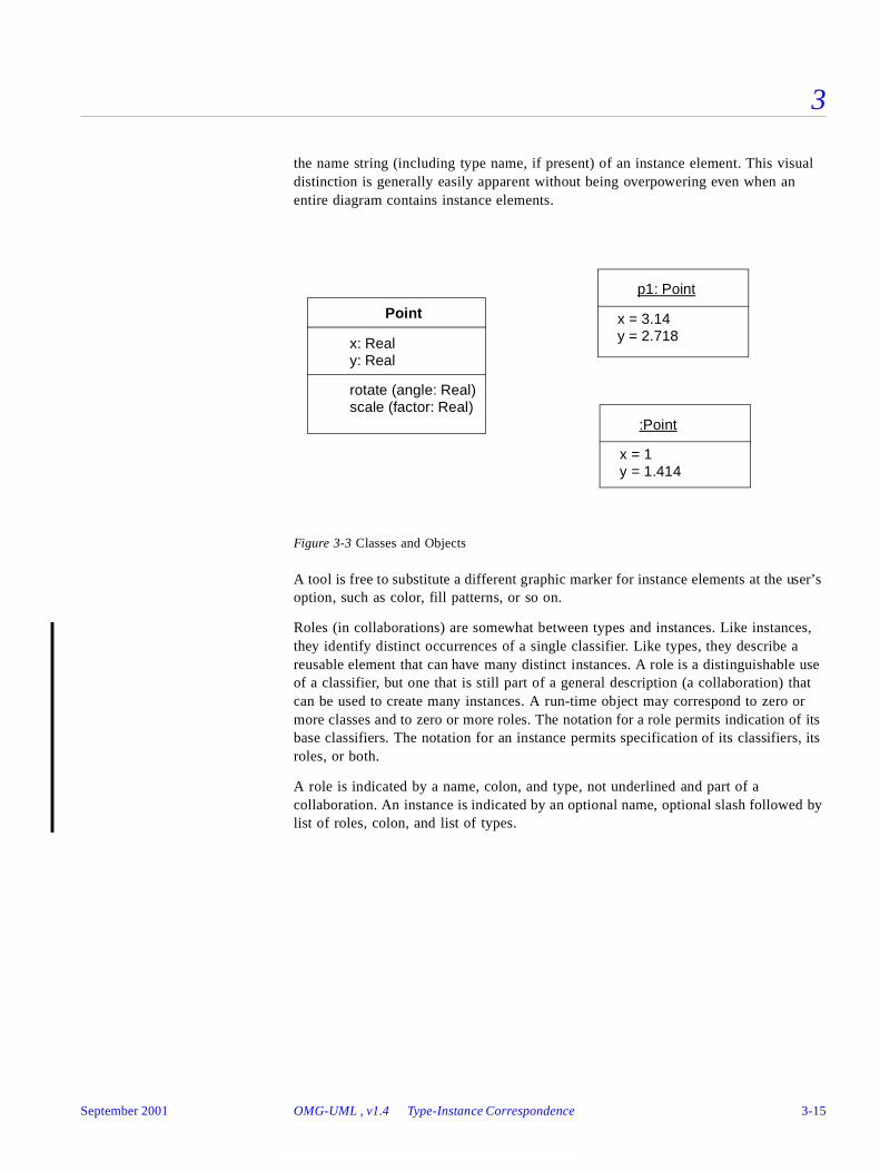
3
the name string (including type name, if present) of an instance element. This visual distinction is generally easily apparent without being overpowering even when an entire diagram contains instance elements.
Figure 3-3 Classes and Objects
A tool is free to substitute a different graphic marker for instance elements at the user’s option, such as color, fill patterns, or so on.
Roles (in collaborations) are somewhat between types and instances. Like instances, they identify distinct occurrences of a single classifier. Like types, they describe a reusable element that can have many distinct instances. A role is a distinguishable use of a classifier, but one that is still part of a general description (a collaboration) that can be used to create many instances. A run-time object may correspond to zero or more classes and to zero or more roles. The notation for a role permits indication of its base classifiers. The notation for an instance permits specification of its classifiers, its roles, or both.
A role is indicated by a name, colon, and type, not underlined and part of a collaboration. An instance is indicated by an optional name, optional slash followed by list of roles, colon, and list of types.
Point
x: Realy: Real
rotate (angle: Real)scale (factor: Real)
p1: Point
x = 3.14y = 2.718
:Point
x = 1y = 1.414
September 2001 OMG-UML , v1.4 Type-Instance Correspondence 3-15
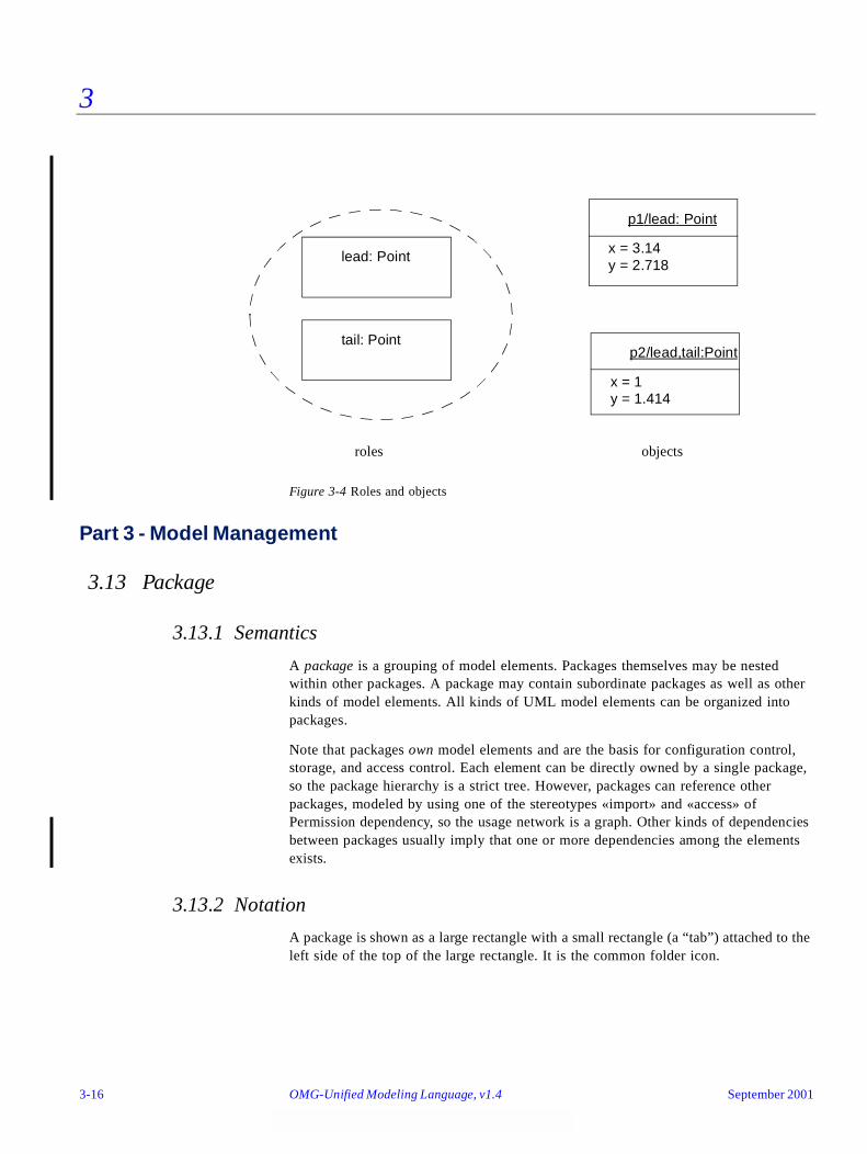
3
Figure 3-4 Roles and objects
Part 3 - Model Management
3.13 Package
3.13.1 Semantics
A package is a grouping of model elements. Packages themselves may be nested within other packages. A package may contain subordinate packages as well as other kinds of model elements. All kinds of UML model elements can be organized into packages.
Note that packages own model elements and are the basis for configuration control, storage, and access control. Each element can be directly owned by a single package, so the package hierarchy is a strict tree. However, packages can reference other packages, modeled by using one of the stereotypes «import» and «access» of Permission dependency, so the usage network is a graph. Other kinds of dependencies between packages usually imply that one or more dependencies among the elements exists.
3.13.2 Notation
A package is shown as a large rectangle with a small rectangle (a “tab”) attached to the left side of the top of the large rectangle. It is the common folder icon.
p1/lead: Point
x = 3.14y = 2.718
p2/lead,tail:Point
x = 1y = 1.414
lead: Point
tail: Point
roles objects
3-16 OMG-Unified Modeling Language, v1.4 September 2001
3
The contents of the package may be shown within the large rectangle. Contents may also be shown by branching lines to contained elements, drawn outside of the package (see Figure 3-5 on page 3-18). A plus sign (+) within a circle is drawn at the end attached to the container.
• If the contents of the package are not shown within the large rectangle, then the name of the package may be placed within the large rectangle.
• If the contents of the package are shown within the large rectangle, then the name of the package may be placed within the tab.
A keyword string may be placed above the package name. The predefined stereotypes facade, framework, stub, and topLevel are notated within guillemets.
A list of properties may be placed in braces after or below the package name. Example: {abstract}. See Section 3.17, “Element Properties,” on page3-29 for details of property syntax.
The visibility of a package element outside the package may be indicated by preceding the name of the element by a visibility symbol (‘+’ for public, ‘-’ for private, ‘#’ for protected, ‘~’ for package).
Relationships may be drawn between package symbols to show relationships between some of the elements in the packages. An import or access relationship between two packages is drawn as a dashed arrow with open arrowhead, labeled with the string «import» or «access», respectively.
Elements from imported or accessed packages may be shown outside the package symbol. As (public) elements in imported packages are added to the client namespace, they may alternatively be drawn inside the package symbol.
3.13.3 Presentation Options
A tool may show visibility by a graphic marker, such as color or font.
A tool may also show visibility by selectively displaying those elements that meet a given visibility level; for example, all of the public elements only.
A diagram showing a package with contents must not necessarily show all its contents; it may show a subset of the contained elements according to some criterion.
3.13.4 Style Guidelines
It is expected that packages with large contents will be shown as simple icons with names, in which the contents may be dynamically accessed by “zooming” to a detailed view.
September 2001 OMG-UML , v1.4 Package 3-17
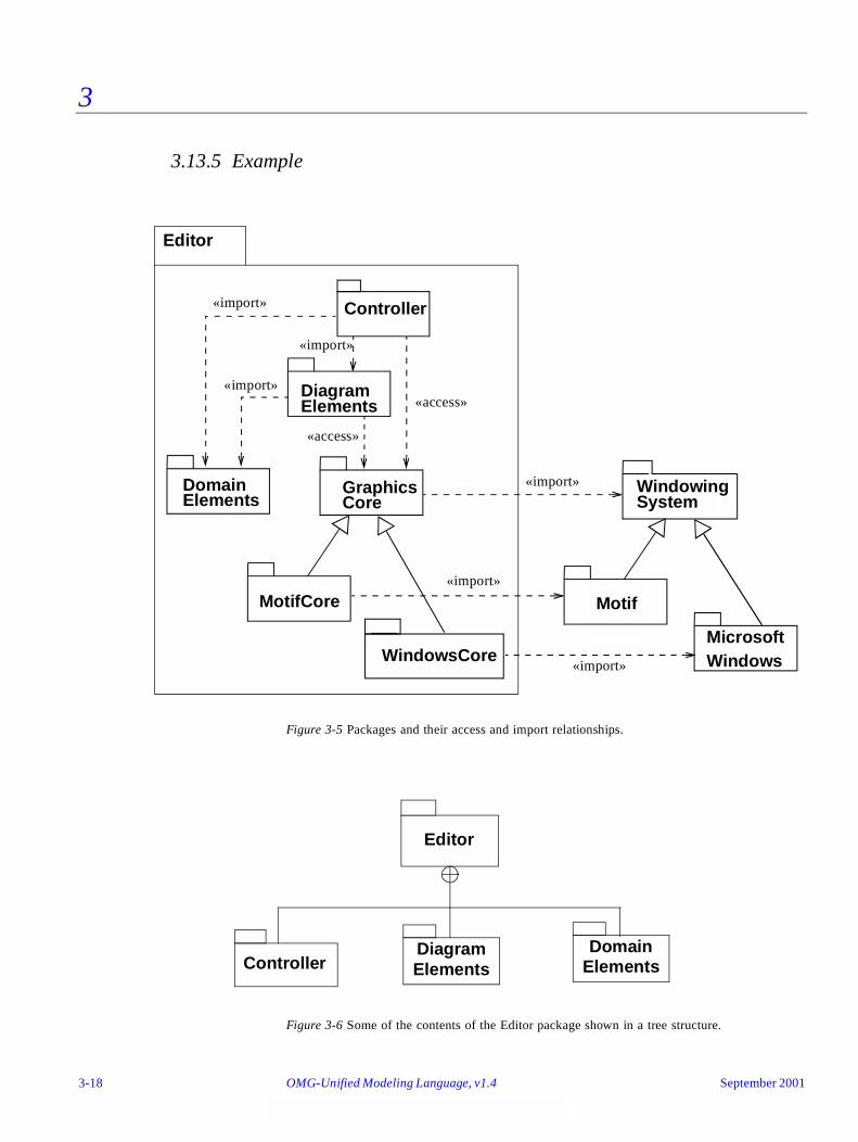
3
3.13.5 Example
Figure 3-5 Packages and their access and import relationships.
Figure 3-6 Some of the contents of the Editor package shown in a tree structure.
Controller
DiagramElements
WindowingSystem
DomainElements
GraphicsCore
MicrosoftWindows
Motif
WindowsCore
MotifCore
Editor
«import»
«import»
«import»
«import»
«import»
«import»
«access»
«access»
Editor
ControllerDiagram Elements
Domain Elements
3-18 OMG-Unified Modeling Language, v1.4 September 2001

3
3.13.6 Mapping
A package symbol maps into a Package element. The name on the package symbol is the name of the Package element. If there is a string above the package name other than «model» or «subsystem», then it maps into a Package element with the corresponding stereotype. If there is a string «model» or «subsystem», then it maps into a Model or Subsystem element, respectively.
A relationship icon drawn from the package symbol boundary to another package symbol maps into a corresponding relationship to the other package element.
A symbol directly contained within the package symbol; that is, not contained within another symbol maps into a model element either owned or referenced by the package element. The alias used for a referenced element is often its pathname, in which case it is directly visible from the diagram that the element is not owned by the package. Only the reference is owned by the current package. Alternatively, a symbol shown outside the package symbol, attached to one of the symbols within the package symbol, denotes a referenced model element.
Symbols connected to the package symbol by branching lines with a plus sign at the end attached to the package symbol, map to elements in the package.
3.14 Subsystem
3.14.1 Semantics
Whereas a package is a generic mechanism for organizing model elements, a subsystem represents a behavioral unit in the physical system, and hence in the model. A subsystem offers interfaces and has operations, and its contents are partitioned into specification and realization elements. The specification of the subsystem consists of operations on the subsystem, together with specification elements such as use cases, state machines.
Apart from defining a namespace, a subsystem serves as a specification unit for the behavior of its contained model elements. A subsystem may or may not be instantiable.
3.14.2 Notation
A subsystem is notated basically in the same way as a package, with the addition of a fork symbol placed in the upper right corner of the large rectangle. The name of the subsystem (together with optional keyword, stereotype) is placed within the large rectangle. Optionally, especially if contents of the subsystem are shown within the large rectangle, the subsystem name and the fork are placed within the tab (the small rectangle).
An instantiable subsystem has the string «instantiable» above its name.
The large rectangle has three compartments, one for operations and one for each of the subsets specification elements and realization elements. These are usually shown by dividing the rectangle by a vertical line, and then dividing the area to the left of this
September 2001 OMG-UML , v1.4 Subsystem 3-19
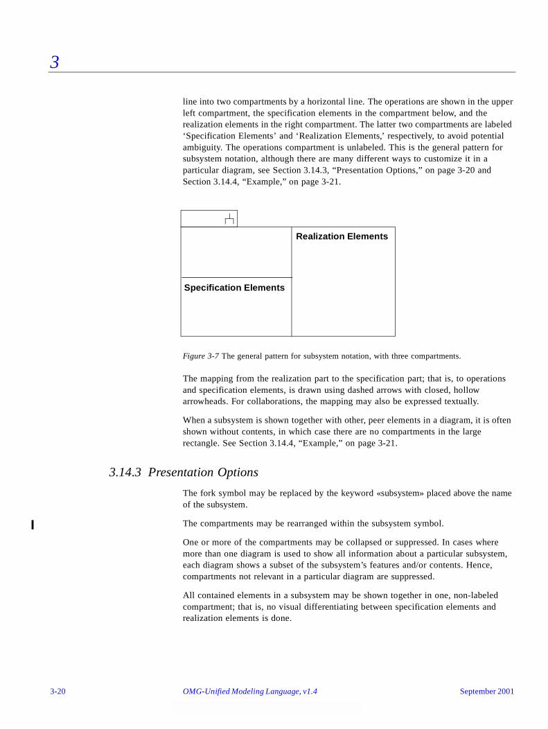
3
line into two compartments by a horizontal line. The operations are shown in the upper left compartment, the specification elements in the compartment below, and the realization elements in the right compartment. The latter two compartments are labeled ‘Specification Elements’ and ‘Realization Elements,’ respectively, to avoid potential ambiguity. The operations compartment is unlabeled. This is the general pattern for subsystem notation, although there are many different ways to customize it in a particular diagram, see Section 3.14.3, “Presentation Options,” on page 3-20 and Section 3.14.4, “Example,” on page 3-21.
Figure 3-7 The general pattern for subsystem notation, with three compartments.
The mapping from the realization part to the specification part; that is, to operations and specification elements, is drawn using dashed arrows with closed, hollow arrowheads. For collaborations, the mapping may also be expressed textually.
When a subsystem is shown together with other, peer elements in a diagram, it is often shown without contents, in which case there are no compartments in the large rectangle. See Section 3.14.4, “Example,” on page 3-21.
3.14.3 Presentation Options
The fork symbol may be replaced by the keyword «subsystem» placed above the name of the subsystem.
The compartments may be rearranged within the subsystem symbol.
One or more of the compartments may be collapsed or suppressed. In cases where more than one diagram is used to show all information about a particular subsystem, each diagram shows a subset of the subsystem’s features and/or contents. Hence, compartments not relevant in a particular diagram are suppressed.
All contained elements in a subsystem may be shown together in one, non-labeled compartment; that is, no visual differentiating between specification elements and realization elements is done.
Specification Elements
Realization Elements
3-20 OMG-Unified Modeling Language, v1.4 September 2001

3
Tools may provide alternative ways to differentiate specification elements from realization elements, such as different colors, using the keyword «specification» for specification elements, etc.
As with packages, the contents of a subsystem may be shown using tree notation. Distinction between specification and realization elements may then be done; for example, by having two separate, labeled branches, or by showing the category separately for each element in the tree as suggested above.
3.14.4 Example
Figure 3-8 An overview diagram showing subsystems with interfaces and their dependencies.
Figure 3-9 All contained elements of a subsystem shown together without division intocompartments. Here, the subsystem offers operation1(...) although this is notexplicitly shown.
In Figure 3-9 no visual separation between specification and realization elements is made. The following three figures are schematic examples where the specification/realization distinction is explicit. Together these figures constitute an example of how the basic notation for subsystem can be used to show different “views” of a subsystem in different diagrams, together giving the whole picture of the subsystem.
SS1
SS2 SS3
operation1(...) : Type1
«Interface»
September 2001 OMG-UML , v1.4 Subsystem 3-21
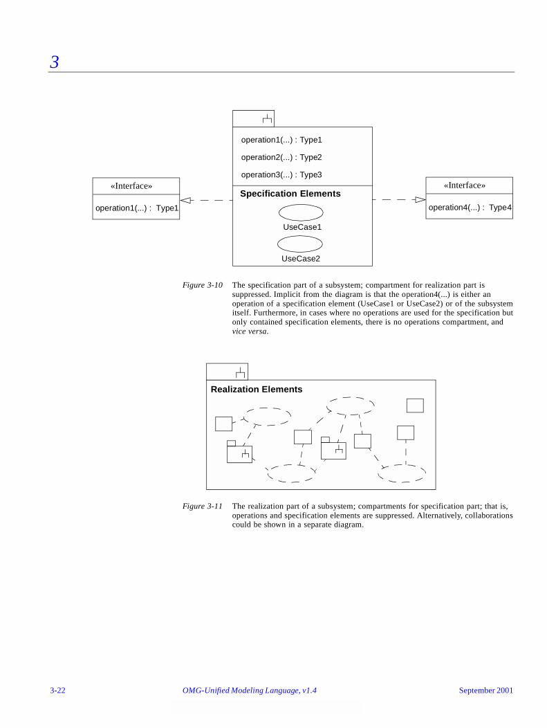
3
Figure 3-10 The specification part of a subsystem; compartment for realization part issuppressed. Implicit from the diagram is that the operation4(...) is either anoperation of a specification element (UseCase1 or UseCase2) or of the subsystemitself. Furthermore, in cases where no operations are used for the specification butonly contained specification elements, there is no operations compartment, andvice versa.
Figure 3-11 The realization part of a subsystem; compartments for specification part; that is, operations and specification elements are suppressed. Alternatively, collaborationscould be shown in a separate diagram.
operation2(...) : Type2
operation3(...) : Type3
UseCase1
UseCase2
Specification Elements
operation1(...) : Type1
«Interface»
operation4(...) : Type4
«Interface»
operation1(...) : Type1
Realization Elements
3-22 OMG-Unified Modeling Language, v1.4 September 2001
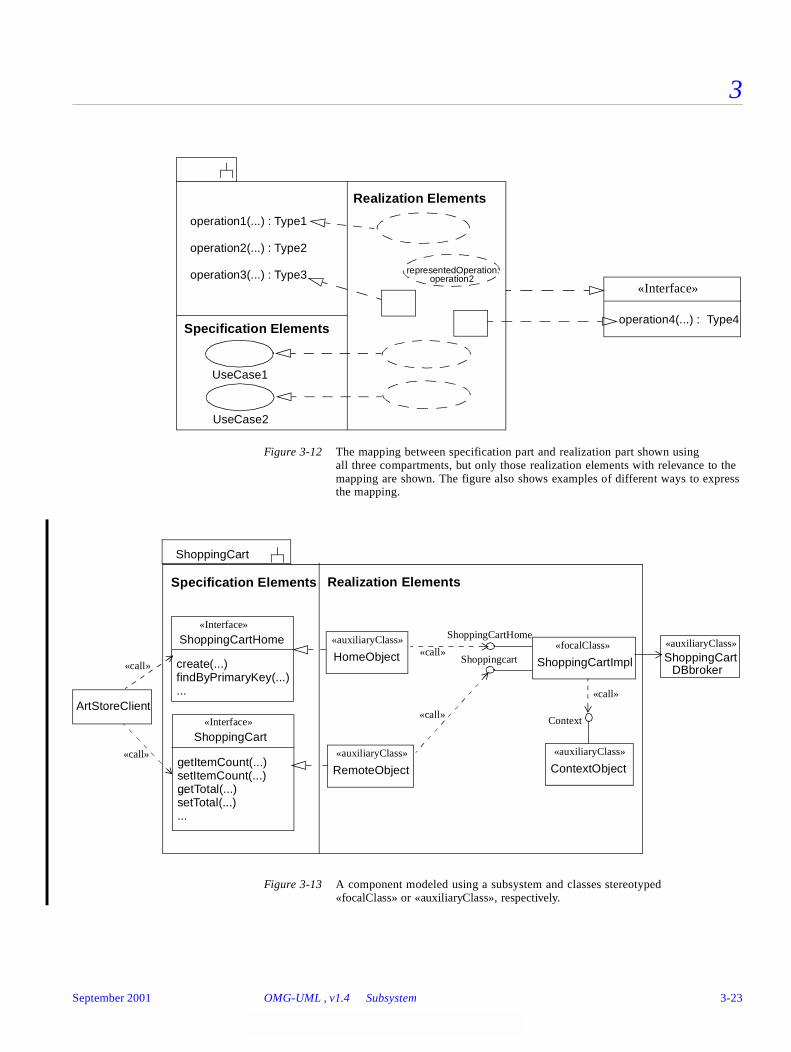
3
Figure 3-12 The mapping between specification part and realization part shown using all three compartments, but only those realization elements with relevance to themapping are shown. The figure also shows examples of different ways to expressthe mapping.
Figure 3-13 A component modeled using a subsystem and classes stereotyped«focalClass» or «auxiliaryClass», respectively.
Realization Elements
operation1(...) : Type1
operation2(...) : Type2
representedOperation: operation2
Specification Elements
operation3(...) : Type3
operation4(...) : Type4
«Interface»
UseCase1
UseCase2
Realization ElementsSpecification Elements
create(...)
«Interface»
ShoppingCartHome
findByPrimaryKey(...)...
getItemCount(...)
«Interface»
ShoppingCart
setItemCount(...)...getTotal(...)setTotal(...)...
«focalClass»
ShoppingCartImpl
«auxiliaryClass»
ContextObject«auxiliaryClass»
RemoteObject
«auxiliaryClass»
HomeObject
Context
ShoppingCartHome
Shoppingcart«call»
«call»
«call»
ShoppingCart
«auxiliaryClass»ShoppingCart
ArtStoreClient
«call»
«call»
DBbroker
September 2001 OMG-UML , v1.4 Subsystem 3-23

3
3.14.5 Mapping
A subsystem symbol maps into a Subsystem with the given name. The mapping is analogous to that of package symbols, with the following addition:
A symbol within a compartment of the large rectangle labeled ‘Specification Elements’ or ‘Realization Elements’ is mapped to a specification or realization element of the subsystem, respectively. An operation signature string within a non-labeled compartment maps to an operation of the subsystem. Note that a compartment may coincide with the whole rectangle.
A symbol, that is not an operation signature string, within a non-labeled compartment maps to an element contained in the subsystem.
A dashed arrow with closed, hollow arrowhead from a symbol denoting a realization element to a symbol denoting a specification element or an operation maps to a «realize» relationship between the corresponding elements.
3.15 Model
3.15.1 Semantics
A model captures a view of a physical system. Hence, it is an abstraction of the physical system with a certain purpose ; for example, to describe behavioral aspects of the physical system to a certain category of stakeholders. A model contains all the model elements needed to represent a physical system completely according to the purpose of this particular model. The model elements in a model are organized into a package/subsystem hierarchy, where the top-most package/subsystem represents the boundary of the physical system.
Different models of the same physical system show different aspects of the system. The pre-defined stereotype «systemModel» can be applied to a model containing the entire set of models for a physical system.
Relationships between elements in different models have no semantic impact on the contents of the models because of the self-containment of models. However, they are useful for tracing refinements and for keeping track of requirements between models.
Relationships between models express refinement, import, etc.
3.15.2 Notation
A model is notated using the ordinary package symbol with a small triangle in the upper right corner of the large rectangle. Optionally, especially if contents of the model is shown within the large rectangle, the triangle may be drawn to the right of the model name in the tab.
3-24 OMG-Unified Modeling Language, v1.4 September 2001

3
Relationships between models as well as relationships between elements in different models are shown using the notation for the given kind of relationship. In particular, trace dependencies are notated with a dashed line, with an optional open arrowhead, and the keyword «trace».
3.15.3 Presentation Options
A model may be notated as a package, using the ordinary package symbol with the keyword «model» placed above the name of the model.
3.15.4 Example
Figure 3-14 Three views of a physical system, each represented by a model.
Figure 3-15 A «systemModel» containing an analysis model and a design model.
AnalysisUse Case Design Model Model Model
«systemModel»
Analysis Design Model Model
September 2001 OMG-UML , v1.4 Model 3-25
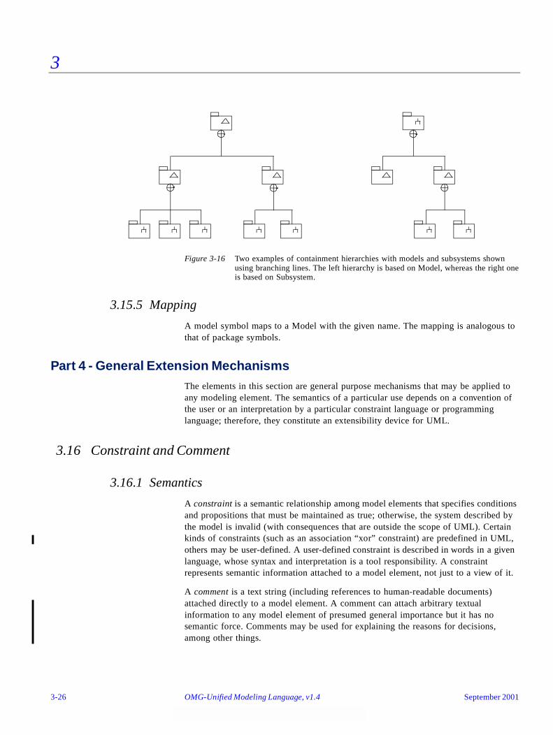
3
Figure 3-16 Two examples of containment hierarchies with models and subsystems shownusing branching lines. The left hierarchy is based on Model, whereas the right oneis based on Subsystem.
3.15.5 Mapping
A model symbol maps to a Model with the given name. The mapping is analogous to that of package symbols.
Part 4 - General Extension MechanismsThe elements in this section are general purpose mechanisms that may be applied to any modeling element. The semantics of a particular use depends on a convention of the user or an interpretation by a particular constraint language or programming language; therefore, they constitute an extensibility device for UML.
3.16 Constraint and Comment
3.16.1 Semantics
A constraint is a semantic relationship among model elements that specifies conditions and propositions that must be maintained as true; otherwise, the system described by the model is invalid (with consequences that are outside the scope of UML). Certain kinds of constraints (such as an association “xor” constraint) are predefined in UML, others may be user-defined. A user-defined constraint is described in words in a given language, whose syntax and interpretation is a tool responsibility. A constraint represents semantic information attached to a model element, not just to a view of it.
A comment is a text string (including references to human-readable documents) attached directly to a model element. A comment can attach arbitrary textual information to any model element of presumed general importance but it has no semantic force. Comments may be used for explaining the reasons for decisions, among other things.
3-26 OMG-Unified Modeling Language, v1.4 September 2001
3
3.16.2 Notation
A constraint is shown as a text string in braces ( { } ). There is an expectation that individual tools may provide one or more languages in which formal constraints may be written. One predefined language for writing constraints is OCL (see the Object Constraint Language Specification chapter); otherwise, the constraint may be written in natural language. Each constraint is written in a specific language, although the language is not generally displayed on the diagram (the tool must keep track of it, however).
For an element whose notation is a text string (such as an attribute, etc.), the constraint string may follow the element text string in braces.
For a list of elements whose notation is a list of text strings (such as the attributes within a class), a constraint string may appear as an element in the list. The constraint applies to all succeeding elements of the list until another constraint string list element or the end of the list. A constraint attached to an individual list element does not supersede the general constraint, but may augment or modify individual constraints within the constraint string.
For a single graphical symbol (such as a class or an association path), the constraint string may be placed near the symbol, preferably near the name of the symbol, if any.
For two graphical symbols (such as two classes or two associations), the constraint is shown as a dashed arrow from one element to the other element labeled by the constraint string (in braces). The direction of the arrow is relevant information within the constraint. The client (tail of the arrow) is mapped to the first position and the supplier (head of the arrow) is mapped to the second position in the constraint.
For three or more graphical symbols, the constraint string is placed in a note symbol and attached to each of the symbols by a dashed line. This notation may also be used for the other cases. For three or more paths of the same kind (such as generalization paths or association paths), the constraint may be attached to a dashed line crossing all of the paths.
A comment is shown as a text string (not enclosed in braces) within a note icon. Syntax for including comments within other elements (such as expressions or constraints) are not specified by UML but may be provided by a tool as part of the expression syntax for a particular language.
September 2001 OMG-UML , v1.4 Constraint and Comment 3-27
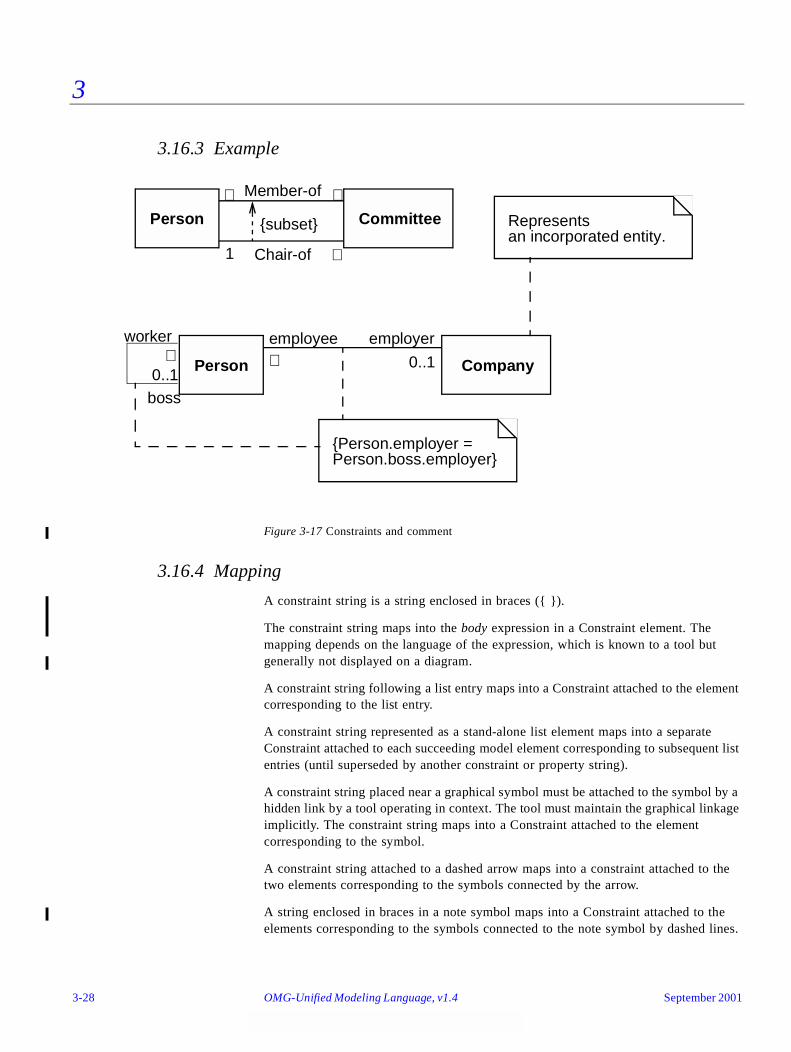
3
3.16.3 Example
Figure 3-17 Constraints and comment
3.16.4 Mapping
A constraint string is a string enclosed in braces ({ }).
The constraint string maps into the body expression in a Constraint element. The mapping depends on the language of the expression, which is known to a tool but generally not displayed on a diagram.
A constraint string following a list entry maps into a Constraint attached to the element corresponding to the list entry.
A constraint string represented as a stand-alone list element maps into a separate Constraint attached to each succeeding model element corresponding to subsequent list entries (until superseded by another constraint or property string).
A constraint string placed near a graphical symbol must be attached to the symbol by a hidden link by a tool operating in context. The tool must maintain the graphical linkage implicitly. The constraint string maps into a Constraint attached to the element corresponding to the symbol.
A constraint string attached to a dashed arrow maps into a constraint attached to the two elements corresponding to the symbols connected by the arrow.
A string enclosed in braces in a note symbol maps into a Constraint attached to the elements corresponding to the symbols connected to the note symbol by dashed lines.
Member-of
Chair-of
{subset}Person Committee
Person Company
boss
{Person.employer =Person.boss.employer}
employerworker employee
0..1
∗ ∗
∗
∗
∗ 0..1
1
Representsan incorporated entity.
3-28 OMG-Unified Modeling Language, v1.4 September 2001
3
A string (not enclosed in braces) in a note attached to the symbol for an element maps into a Comment attached to the corresponding element.
3.17 Element Properties
Many kinds of elements have detailed properties that do not have a visual notation. In addition, users can define new element properties using the tagged value mechanism.
A string may be used to display properties attached to a model element. This includes properties represented by attributes in the metamodel as well as both predefined and user-defined tagged values.
3.17.1 Semantics
Note that we use property in a general sense to mean any value attached to a model element, including attributes, associations, and tagged values. In this sense it can include indirectly reachable values that can be found starting at a given element. Some kinds of properties would have syntax within expressions (not specified by UML) but no explicit UML notation.
A tagged value is a keyword-value pair that may be attached to any kind of model element (including diagram elements as well as semantic model elements). The keyword is called a tag. Each tag represents a particular kind of property applicable to one or many kinds of model elements. Both the tag and the value are encoded as strings. Tagged values are an extensibility mechanism of UML permitting arbitrary information to be attached to models. It is expected that most model editors will provide basic facilities for defining, displaying, and searching tagged values as strings but will not otherwise use them to extend the UML semantics. It is expected, however, that back-end tools such as code generators, report writers, and the like will read tagged values to guide their semantics in flexible ways.
3.17.2 Notation
A property (either a metamodel attribute or a tagged value) is displayed as a comma-delimited sequence of property specifications all inside a pair of braces ( { } ).
A property specification has the form
name = value
where name is the name of a property (metamodel attribute or arbitrary tag) and value is an arbitrary string that denotes its value. If the type of the property is Boolean, then the default value is true if the value is omitted. That is, to specify a value of true you may include just the keyword. To specify a value of false, you omit the name completely. Properties of other types require explicit values. The syntax for displaying the value is a tool responsibility in cases where the underlying model value is not a string or a number.
Note that property strings may be used to display built-in attributes as well as tagged values.
September 2001 OMG-UML , v1.4 Element Properties 3-29
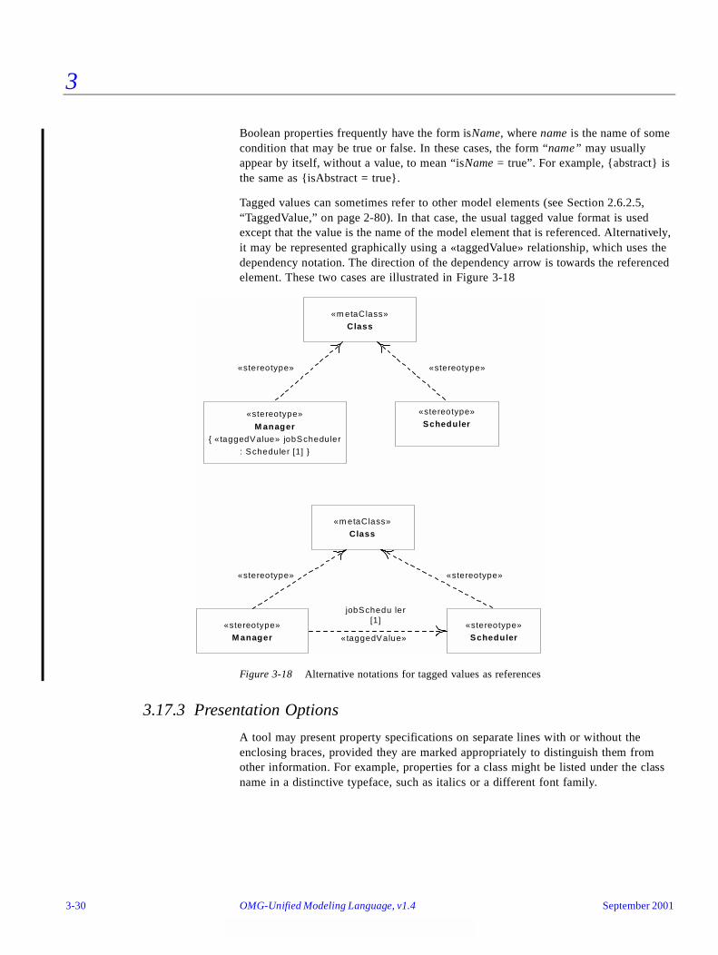
3
Boolean properties frequently have the form isName, where name is the name of some condition that may be true or false. In these cases, the form “name” may usually appear by itself, without a value, to mean “isName = true”. For example, {abstract} is the same as {isAbstract = true}.
Tagged values can sometimes refer to other model elements (see Section 2.6.2.5, “TaggedValue,” on page 2-80). In that case, the usual tagged value format is used except that the value is the name of the model element that is referenced. Alternatively, it may be represented graphically using a «taggedValue» relationship, which uses the dependency notation. The direction of the dependency arrow is towards the referenced element. These two cases are illustrated in Figure 3-18
Figure 3-18 Alternative notations for tagged values as references
3.17.3 Presentation Options
A tool may present property specifications on separate lines with or without the enclosing braces, provided they are marked appropriately to distinguish them from other information. For example, properties for a class might be listed under the class name in a distinctive typeface, such as italics or a different font family.
«stereotype»
Scheduler«stereotype»
M anager{ «taggedValue» jobScheduler
: Scheduler [1] }
«m etaClass»
Class
«stereotype»
Scheduler«stereotype»
M anager
«m etaClass»
Class
jobSchedu ler[1]
«stereotype»«stereotype»
«taggedValue»
«stereotype»«stereotype»
3-30 OMG-Unified Modeling Language, v1.4 September 2001

3
3.17.4 Style Guidelines
It is legal to use strings to specify properties that have graphical notations; however, such usage may be confusing and should be used with care.
3.17.5 Example
{ author = “Joe Smith”, deadline = 31-March-1997, status = analysis }
{ abstract }
3.17.6 Mapping
Each term within a string maps to either a built-in attribute of a model element or a tagged value (predefined or user-defined). A tool must enforce the correspondence to built-in attributes.
3.18 Stereotypes
3.18.1 Semantics
A stereotype is, in effect, a new class of metamodel element that is introduced at modeling time. It represents a subclass of an existing metamodel element with the same form (attributes and relationships) but with a different intent. Generally a stereotype represents a usage distinction. A stereotyped element may have additional constraints on it from the base metamodel class. It may also have required tagged values that add information needed by elements with the stereotype. It is expected that code generators and other tools will treat stereotyped elements specially. Stereotypes represent one of the built-in extensibility mechanisms of UML.
3.18.2 Notation
The general presentation of a stereotype is to use the symbol for the metamodel base element but to place a keyword string above the name of the element (if any). The keyword string (Section 3.9, “Keywords,” on page 3-11) is the name of the stereotype within matched guillemets, which are the quotation mark symbols used in French and certain other languages (for example, «foo»).
Note – A guillemet looks like a double angle-bracket, but it is a single character in most extended fonts. Most computers have a Character Map utility. Double angle-brackets may be used as a substitute by the typographically challenged.
The keyword string is generally placed above or in front of the name of the model element being described. If multiple stereotypes are defined for the same model element, they are placed vertically one below the other. The keyword string may also be used as an element in a list, in which case it applies to subsequent list elements until
September 2001 OMG-UML , v1.4 Stereotypes 3-31
3
another stereotype string replaces it, or an empty stereotype string («») nullifies it. Note that a stereotype name should not be identical to a predefined keyword applicable to the same element type.
To permit limited graphical extension of the UML notation as well, a graphic icon or a graphic marker (such as texture or color) can be associated with a stereotype. The UML does not specify the form of the graphic specification, but many bitmap and stroked formats exist (and their portability is a difficult problem). The icon can be used in one of two ways:
1. It may be used instead of, or in addition to, the stereotype keyword string as part of the symbol for the base model element that the stereotype is based on. For example, in a class rectangle it is placed in the upper right corner of the name compartment. In this form, the normal contents of the item can be seen.
2. The entire base model element symbol may be “collapsed” into an icon containing the element name or with the name above or below the icon. Other information contained by the base model element symbol is suppressed. More general forms of icon specification and substitution are conceivable, but we leave these to the ingenuity of tool builders, with the warning that excessive use of extensibility capabilities may lead to loss of portability among tools.
If multiple stereotypes are defined, the graphical icons or markers are omitted.
UML avoids the use of graphic markers, such as color, that present challenges for certain persons (the color blind) and for important kinds of equipment (such as printers, copiers, and fax machines). None of the UML symbols require the use of such graphic markers. Users may use graphic markers freely in their personal work for their own purposes (such as for highlighting within a tool) but should be aware of their limitations for interchange and be prepared to use the canonical forms when necessary.
The classification hierarchy of the stereotypes themselves can be displayed on a class diagram, as described in Section 3.35, “Stereotype Declaration,” on page 3-57. This capability is not required by many modelers who must use existing stereotypes but not define new kinds of stereotypes.
3.18.3 Examples
Figure 3-19 on page 3-33 illustrates various notational forms of the stereotype notation. Note that the top four shapes are alternatives of each other. The next one shows how a dependency can be stereotyped and the bottom example illustrates a model element with multiple stereotypes.
3-32 OMG-Unified Modeling Language, v1.4 September 2001

3
Figure 3-19 Varieties of Stereotype Notation
3.18.4 Mapping
The use of a stereotype keyword maps into the stereotype relationship between the Element corresponding to the symbol containing the name and the Stereotype of the given name. The use of a stereotype icon within a symbol maps into the stereotype relationship between the Element corresponding to the symbol containing the icon and the Stereotype represented by the symbol. A tool must establish the connection when the symbol is created and there is no requirement that an icon represent uniquely one stereotype. The use of a stereotype icon, instead of a symbol, must be created in a context in which a tool implies a corresponding model element and a Stereotype represented by the icon. The element and the stereotype have the stereotype relationship.
PenTracker«control»
PenTracker
«control»
PenTracker
PenTracker
JobManager Scheduler«call»
location: Point
enable (Mode)
location: Point
enable (Mode)
location: Point
enable (Mode)
Lock
«control»
reqQueue: Queue
«semaphore»
September 2001 OMG-UML , v1.4 Stereotypes 3-33

3
Part 5 - Static Structure DiagramsClass diagrams show the static structure of the model, in particular, the things that exist (such as classes and types), their internal structure, and their relationships to other things. Class diagrams do not show temporal information, although they may contain reified occurrences of things that have or things that describe temporal behavior. An object diagram shows instances compatible with a particular class diagram.
This section discusses classes and their variations, including templates and instantiated classes, and the relationships between classes (association and generalization) and the contents of classes (attributes and operations).
3.19 Class Diagram
A class diagram is a graph of Classifier elements connected by their various static relationships. Note that a “class” diagram may also contain interfaces, packages, relationships, and even instances, such as objects and links. Perhaps a better name would be “static structural diagram” but “class diagram” is shorter and well established.
3.19.1 Semantics
A class diagram is a graphic view of the static structural model. The individual class diagrams do not represent divisions in the underlying model.
3.19.2 Notation
A class diagram is a collection of static declarative model elements, such as classes, interfaces, and their relationships, connected as a graph to each other and to their contents. Class diagrams may be organized into packages either with their underlying models or as separate packages that build upon the underlying model packages.
3.19.3 Mapping
A class diagram does not necessarily match a single semantic entity. A package within the static structural model may be represented by one or more class diagrams. The division of the presentation into separate diagrams is for graphical convenience and does not imply a partitioning of the model itself. The contents of a diagram map into elements in the static semantic model. If a diagram is part of a package, then its contents map into elements in the same package (including possible references to elements accessed or imported from other packages).
3-34 OMG-Unified Modeling Language, v1.4 September 2001
3
3.20 Object Diagram
An object diagram is a graph of instances, including objects and data values. A static object diagram is an instance of a class diagram; it shows a snapshot of the detailed state of a system at a point in time. The use of object diagrams is fairly limited, mainly to show examples of data structures.
Tools need not support a separate format for object diagrams. Class diagrams can contain objects, so a class diagram with objects and no classes is an “object diagram.” The phrase is useful, however, to characterize a particular usage achievable in various ways.
3.21 Classifier
Classifier is the metamodel superclass of Class, DataType, and Interface. All of these have similar syntax and are therefore all notated using the rectangle symbol with keywords used as necessary. Because classes are most common in diagrams, a rectangle without a keyword represents a class, and the other subclasses of Classifier are indicated with keywords. In the sections that follow, the discussion will focus on Class, but most of the notation applies to the other element kinds as semantically appropriate and as described later under their own sections.
3.22 Class
A class is the descriptor for a set of objects with similar structure, behavior, and relationships. The model is concerned with describing the intension of the class, that is, the rules that define it. The run-time execution provides its extension, that is, its instances. UML provides notation for declaring classes and specifying their properties, as well as using classes in various ways. Some modeling elements that are similar in form to classes (such as interfaces, signals, or utilities) are notated using keywords on class symbols; some of these are separate metamodel classes and some are stereotypes of Class. Classes are declared in class diagrams and used in most other diagrams. UML provides a graphical notation for declaring and using classes, as well as a textual notation for referencing classes within the descriptions of other model elements.
3.22.1 Semantics
A class represents a concept within the system being modeled. Classes have data structure and behavior and relationships to other elements.
The name of a class has scope within the package in which it is declared and the name must be unique (among class names) within its package.
September 2001 OMG-UML , v1.4 Object Diagram 3-35
3
3.22.2 Basic Notation
A class is drawn as a solid-outline rectangle with three compartments separated by horizontal lines. The top name compartment holds the class name and other general properties of the class (including stereotype); the middle list compartment holds a list of attributes; the bottom list compartment holds a list of operations.
See Section 3.23, “Name Compartment,” on page 3-38 and Section 3.24, “List Compartment,” on page 3-38 for more details.
3.22.2.1 References
By default a class shown within a package is assumed to be defined within that package. To show a reference to a class defined in another package, use the syntax
Package-name::Class-name
as the name string in the name compartment. A full pathname can be specified by chaining together package names separated by double colons (::).
3.22.3 Presentation Options
Either or both of the attribute and operation compartments may be suppressed. A separator line is not drawn for a missing compartment. If a compartment is suppressed, no inference can be drawn about the presence or absence of elements in it. Compartment names can be used to remove ambiguity, if necessary (Section 3.24, “List Compartment,” on page 3-38).
Additional compartments may be supplied as a tool extension to show other predefined or user-defined model properties (for example, to show business rules, responsibilities, variations, events handled, exceptions raised, and so on). Most compartments are simply lists of strings. More complicated formats are possible, but UML does not specify such formats; they are a tool responsibility. Appearance of each compartment should preferably be implicit based on its contents. Compartment names may be used, if needed.
Tools may provide other ways to show class references and to distinguish them from class declarations.
A class symbol with a stereotype icon may be “collapsed” to show just the stereotype icon, with the name of the class either inside the class or below the icon. Other contents of the class are suppressed.
3.22.4 Style Guidelines
• Center class name in boldface.
• Center keyword (including stereotype names) in plain face within guillemets above class name.
3-36 OMG-Unified Modeling Language, v1.4 September 2001
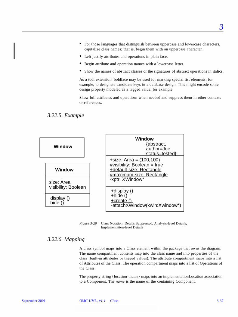
3
• For those languages that distinguish between uppercase and lowercase characters, capitalize class names; that is, begin them with an uppercase character.
• Left justify attributes and operations in plain face.
• Begin attribute and operation names with a lowercase letter.
• Show the names of abstract classes or the signatures of abstract operations in italics.
As a tool extension, boldface may be used for marking special list elements; for example, to designate candidate keys in a database design. This might encode some design property modeled as a tagged value, for example.
Show full attributes and operations when needed and suppress them in other contexts or references.
3.22.5 Example
Figure 3-20 Class Notation: Details Suppressed, Analysis-level Details, Implementation-level Details
3.22.6 Mapping
A class symbol maps into a Class element within the package that owns the diagram. The name compartment contents map into the class name and into properties of the class (built-in attributes or tagged values). The attribute compartment maps into a list of Attributes of the Class. The operation compartment maps into a list of Operations of the Class.
The property string {location=name} maps into an implementationLocation association to a Component. The name is the name of the containing Component.
Window
display ()
size: Areavisibility: Boolean
hide ()
Window
Window
+default-size: Rectangle#maximum-size: Rectangle
+create ()
+display ()
+size: Area = (100,100)#visibility: Boolean = true
+hide ()
-xptr: XWindow*
-attachXWindow(xwin:Xwindow*)
{abstract,author=Joe,status=tested}
September 2001 OMG-UML , v1.4 Class 3-37
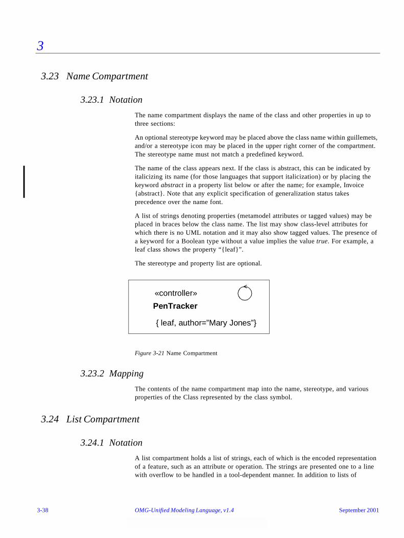
3
3.23 Name Compartment
3.23.1 Notation
The name compartment displays the name of the class and other properties in up to three sections:
An optional stereotype keyword may be placed above the class name within guillemets, and/or a stereotype icon may be placed in the upper right corner of the compartment. The stereotype name must not match a predefined keyword.
The name of the class appears next. If the class is abstract, this can be indicated by italicizing its name (for those languages that support italicization) or by placing the keyword abstract in a property list below or after the name; for example, Invoice {abstract}. Note that any explicit specification of generalization status takes precedence over the name font.
A list of strings denoting properties (metamodel attributes or tagged values) may be placed in braces below the class name. The list may show class-level attributes for which there is no UML notation and it may also show tagged values. The presence of a keyword for a Boolean type without a value implies the value true. For example, a leaf class shows the property “{leaf}”.
The stereotype and property list are optional.
Figure 3-21 Name Compartment
3.23.2 Mapping
The contents of the name compartment map into the name, stereotype, and various properties of the Class represented by the class symbol.
3.24 List Compartment
3.24.1 Notation
A list compartment holds a list of strings, each of which is the encoded representation of a feature, such as an attribute or operation. The strings are presented one to a line with overflow to be handled in a tool-dependent manner. In addition to lists of
PenTracker
«controller»
{ leaf, author=”Mary Jones”}
3-38 OMG-Unified Modeling Language, v1.4 September 2001
3
attributes or operations, optional lists can show other kinds of predefined or user-defined values, such as responsibilities, rules, or modification histories. UML does not define these optional lists. The manipulation of user-defined lists is tool-dependent.
The items in the list are ordered and the order may be modified by the user. The order of the elements is meaningful information and must be accessible within tools (for example, it may be used by a code generator in generating a list of declarations). The list elements may be presented in a different order to achieve some other purpose (for example, they may be sorted in some way). Even if the list is sorted, the items maintain their original order in the underlying model. The ordering information is merely suppressed in the view.
An ellipsis ( . . . ) as the final element of a list or the final element of a delimited section of a list indicates that additional elements in the model exist that meet the selection condition, but that are not shown in that list. Such elements may appear in a different view of the list.
3.24.1.1 Group properties
A property string may be shown as an element of the list, in which case it applies to all of the succeeding list elements until another property string appears as a list element. This is equivalent to attaching the property string to each of the list elements individually. The property string does not designate a model element. Examples of this usage include indicating a stereotype and specifying visibility. Keyword strings may also be used in a similar way to qualify subsequent list elements.
3.24.1.2 Compartment name
A compartment may display a name to indicate which kind of compartment it is. The name is displayed in a distinctive font centered at the top of the compartment. This capability is useful if some compartments are omitted or if additional user-defined compartments are added. For a Class, the predefined compartments are named attributes and operations. An example of a user-defined compartment might be requirements. The name compartment in a class must always be present; therefore, it does not require or permit a compartment name.
3.24.2 Presentation Options
A tool may present the list elements in a sorted order, in which case the inherent ordering of the elements is not visible. A sort is based on some internal property and does not indicate additional model information. Example sort rules include:
• alphabetical order,
• ordering by stereotype (such as constructors, destructors, then ordinary methods),
• ordering by visibility (public, then package, then protected, then private).
The elements in the list may be filtered according to some selection rule. The specification of selection rules is a tool responsibility. The absence of items from a filtered list indicates that no elements meet the filter criterion, but no inference can be
September 2001 OMG-UML , v1.4 List Compartment 3-39
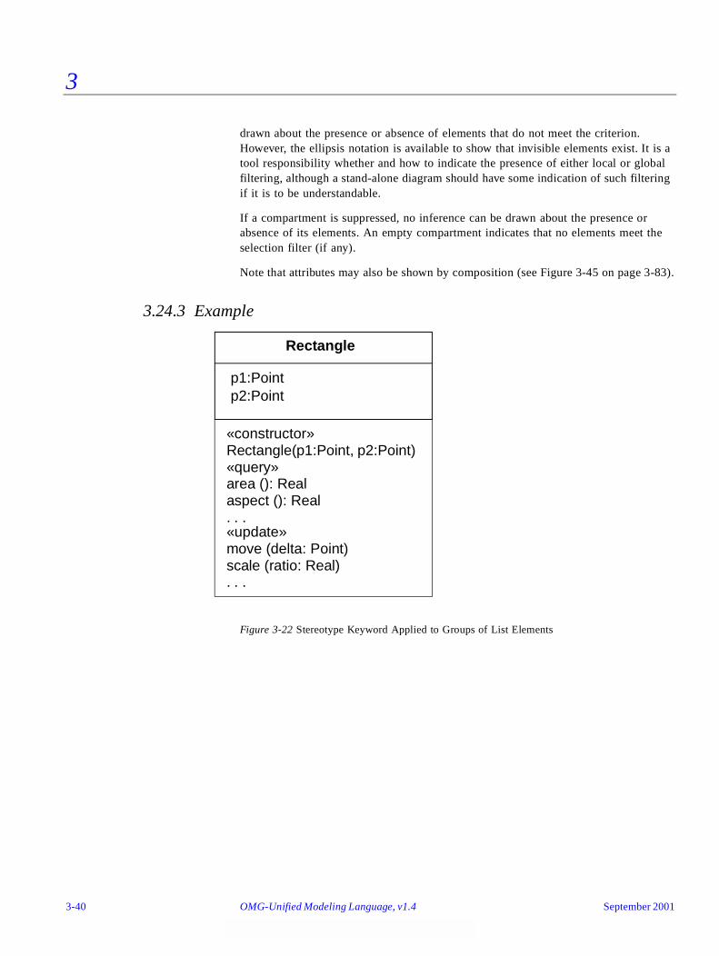
3
drawn about the presence or absence of elements that do not meet the criterion. However, the ellipsis notation is available to show that invisible elements exist. It is a tool responsibility whether and how to indicate the presence of either local or global filtering, although a stand-alone diagram should have some indication of such filtering if it is to be understandable.
If a compartment is suppressed, no inference can be drawn about the presence or absence of its elements. An empty compartment indicates that no elements meet the selection filter (if any).
Note that attributes may also be shown by composition (see Figure 3-45 on page 3-83).
3.24.3 Example
Figure 3-22 Stereotype Keyword Applied to Groups of List Elements
«constructor»Rectangle(p1:Point, p2:Point)«query»area (): Realaspect (): Real
«update»move (delta: Point)scale (ratio: Real). . .
. . .
Rectangle
p1:Pointp2:Point
3-40 OMG-Unified Modeling Language, v1.4 September 2001
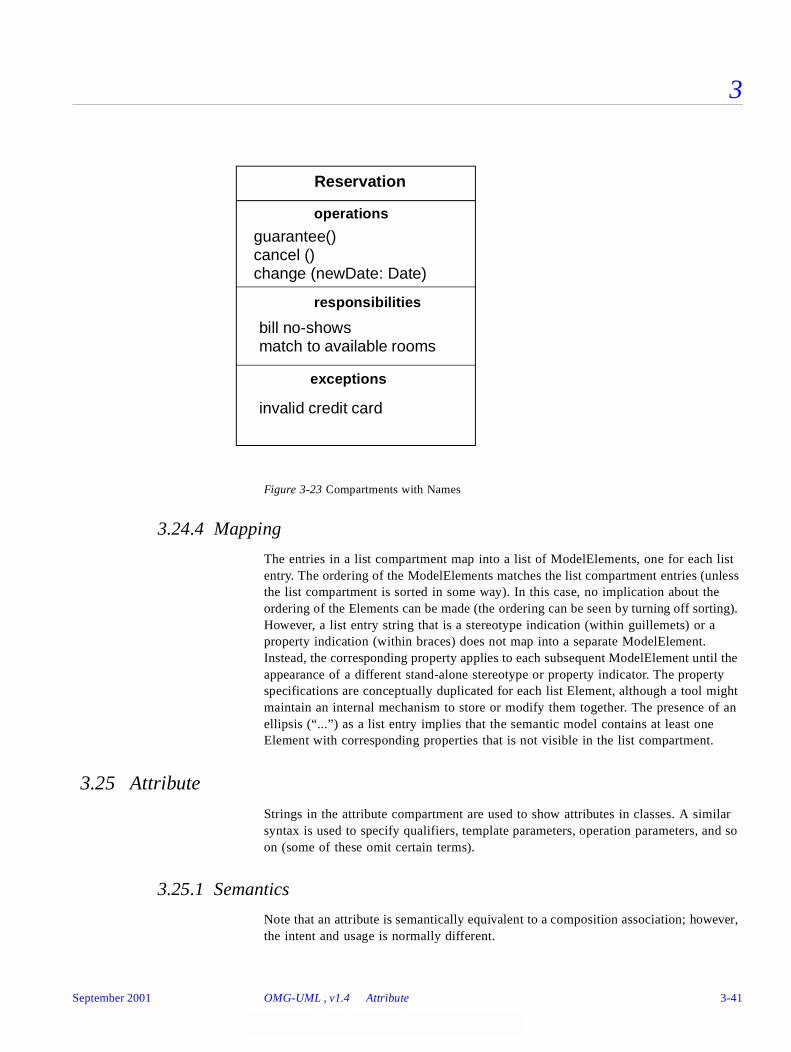
3
Figure 3-23 Compartments with Names
3.24.4 Mapping
The entries in a list compartment map into a list of ModelElements, one for each list entry. The ordering of the ModelElements matches the list compartment entries (unless the list compartment is sorted in some way). In this case, no implication about the ordering of the Elements can be made (the ordering can be seen by turning off sorting). However, a list entry string that is a stereotype indication (within guillemets) or a property indication (within braces) does not map into a separate ModelElement. Instead, the corresponding property applies to each subsequent ModelElement until the appearance of a different stand-alone stereotype or property indicator. The property specifications are conceptually duplicated for each list Element, although a tool might maintain an internal mechanism to store or modify them together. The presence of an ellipsis (“...”) as a list entry implies that the semantic model contains at least one Element with corresponding properties that is not visible in the list compartment.
3.25 Attribute
Strings in the attribute compartment are used to show attributes in classes. A similar syntax is used to specify qualifiers, template parameters, operation parameters, and so on (some of these omit certain terms).
3.25.1 Semantics
Note that an attribute is semantically equivalent to a composition association; however, the intent and usage is normally different.
bill no-shows
Reservation
operations
guarantee()cancel ()change (newDate: Date)
responsibilities
match to available rooms
exceptions
invalid credit card
September 2001 OMG-UML , v1.4 Attribute 3-41
3
The type of an attribute is a Classifier.
3.25.2 Notation
An attribute is shown as a text string that can be parsed into the various properties of an attribute model element. The default syntax is:
visibility name : type-expression [ multiplicity ordering ] = initial-value { property-string }
• Where visibility is one of:
+ public visibility
# protected visibility
- private visibility
~ .package visibility
The visibility marker may be suppressed. The absence of a visibility marker indicates that the visibility is not shown (not that it is undefined or public). A tool should assign visibilities to new attributes even if the visibility is not shown. The visibility marker is a shorthand for a full visibility property specification string.
Visibility may also be specified by keywords (public, protected, private, package). This form is used particularly when it is used as an inline list element that applies to an entire block of attributes.
Additional kinds of visibility might be defined for certain programming languages, such as C++ implementation visibility (actually all forms of nonpublic visibility are language-dependent). Such visibility must be specified by property string or by a tool-specific convention.
• Where name is an identifier string that represents the name of the attribute.
• Where [ multiplicity ordering] shows the multiplicity and the ordering of the attribute (Section 3.44, “Multiplicity,” on page 3-75). The term may be omitted, in which case the multiplicity is 1..1 (exactly one).
• The ordering property is meaningful if the multiplicity upper bound is greater than one. It may be one of:
• (absent) — the values are unordered
• unordered — the values are unordered
• ordered — the values are ordered
• Where type-expression is either
• if it is a simple word, the name of a classifier, or
• a language-dependent string that maps into a ProgrammingLanguageDataType.
• Where initial-value is a language-dependent expression for the initial value of a newly created object. The initial value is optional (the equal sign is also omitted). An explicit constructor for a new object may augment or modify the default initial value.
3-42 OMG-Unified Modeling Language, v1.4 September 2001
3
• Where property-string indicates property values that apply to the element. The property string is optional (the braces are omitted if no properties are specified).
A class-scope attribute is shown by underlining the name and type expression string; otherwise, the attribute is instance-scope.
class-scope-attribute
The notation justification is that a class-scope attribute is an instance value in the executing system, just as an object is an instance value, so both may be designated by underlining. An instance-scope attribute is not underlined; that is the default.
There is no symbol for whether an attribute is changeable (the default is changeable). A nonchangeable attribute is specified with the property “{frozen}”.
In the absence of a multiplicity indicator, an attribute holds exactly 1 value. Multiplicity may be indicated by placing a multiplicity indicator in brackets after the classifier name, for example:
colors : Color [3]points : Point [2..* ordered]
Note that a multiplicity of 0..1 provides for the possibility of null values: the absence of a value, as opposed to a particular value from the range. For example, the following declaration permits a distinction between the null value and the empty string:
name : String [0..1]
A stereotype keyword in guillemets precedes the entire attribute string, including any visibility indicators. A property list in braces follows the rest of the attribute string.
3.25.3 Presentation Options
The type expression may be suppressed (but it has a value in the model).
The initial value may be suppressed, and it may be absent from the model. It is a tool responsibility whether and how to show this distinction.
A tool may show the visibility indication in a different way, such as by using a special icon or by sorting the elements by group.
A tool may show the individual fields of an attribute as columns rather than a continuous string.
If the type-expression string is not a word, then it is assumed to be expressed in the syntax of a particular programming language, such as C++ or Smalltalk. This form is assumed if the string is not a word. Specific tagged properties may be included in the string. The programming language must be known from the general context of the diagram or a tool supporting it. In this case, the type-expression maps into a ProgrammingLanguageDataType whose expression attribute specifies the language name and the string representation of the data type in that language.
Particular attributes within a list may be suppressed (see Section 3.24, “List Compartment,” on page 3-38).
September 2001 OMG-UML , v1.4 Attribute 3-43
3
3.25.4 Style Guidelines
Attribute names typically begin with a lowercase letter. Attribute names are in plain face.
3.25.5 Example
+size: Area = (100,100)#visibility: Boolean = invisible+default-size: Rectangle#maximum-size: Rectangle-xptr: XWindowPtr
3.25.6 Mapping
A string entry within the attribute compartment maps into an Attribute within the Class corresponding to the class symbol. The properties of the attribute map in accord with the preceding descriptions. If the visibility is absent, then no conclusion can be drawn about the Attribute visibilities unless a filter is in effect; for example, only public attributes shown. Likewise, if the type or initial value are omitted. The omission of an underline always indicates an instance-scope attribute. The omission of multiplicity denotes a multiplicity of 1.
Any properties specified in braces following the attribute string map into properties on the Attribute. In addition, any properties specified on a previous stand-alone property specification entry apply to the current Attribute (and to others).
3.26 Operation
Entries in the operation compartment are strings that show operations defined on classes and methods supplied by classes.
3.26.1 Semantics
An operation is a service that an instance of the class may be requested to perform. It has a name and a list of arguments.
3.26.2 Notation
An operation is shown as a text string that can be parsed into the various properties of an operation model element. The default syntax is:
visibility name ( parameter-list ) : return-type-expression { property-string }
• Where visibility is one of:
+ public visibility
# protected visibility
3-44 OMG-Unified Modeling Language, v1.4 September 2001
3
- private visibility
~ package visibility
The visibility marker may be suppressed. The absence of a visibility marker indicates that the visibility is not shown (not that it is undefined or public). The visibility marker is a shorthand for a full visibility property specification string.
Visibility may also be specified by keywords (public, protected, private, package). This form is used particularly when it is used as an inline list element that applies to an entire block of operations.
Additional kinds of visibility might be defined for certain programming languages, such as C++ implementation visibility (actually all forms of nonpublic visibility are language-dependent). Such visibility must be specified by property string or by a tool-specific convention.
• Where name is an identifier string.
• Where return-type-expression is a language-dependent specification of the implementation type or types of the value returned by the operation. The colon and the return-type are omitted if the operation does not return a value (as for C++ void). A list of expressions may be supplied to indicate multiple return values.
• Where parameter-list is a comma-separated list of formal parameters, each specified using the syntax:
kind name : type-expression = default-value
• where kind is in, out, or inout, with the default in if absent.
• where name is the name of a formal parameter.
• where type-expression is the (language-dependent) specification of an implementation type.
• where default-value is an optional value expression for the parameter, expressed in and subject to the limitations of the eventual target language.
• Where property-string indicates property values that apply to the element. The property string is optional (the braces are omitted if no properties are specified).
A class-scope operation is shown by underlining the name and type expression string. An instance-scope operation is the default and is not marked.
An operation that does not modify the system state (one that has no side effects) is specified by the property “{query}”; otherwise, the operation may alter the system state, although there is no guarantee that it will do so.
The concurrency semantics of an operation are specified by a property string of the form “{concurrency = name}, where name is one of the names: sequential, guarded, concurrent. As a shorthand, one of the names may be used by itself in a property string to indicate the corresponding concurrency value. In the absence of a specification, the concurrency semantics are unspecified and must therefore be assumed to be sequential in the worst case.
September 2001 OMG-UML , v1.4 Operation 3-45
3
The top-most appearance of an operation signature declares the operation on the class (and inherited by all of its descendents). If this class does not implement the operation; that is, does not supply a method, then the operation may be marked as “{abstract}” or the operation signature may be italicized to indicate that it is abstract. A subordinate appearance of the operation signature without the {abstract} property indicates that the subordinate class implements a method on the operation.
The actual text or algorithm of a method may be indicated in a note attached to the operation entry.
If the objects of a class accept and respond to a given signal, an operation entry with the keyword «signal» indicates that the class accepts the given signal. The syntax is identical to that of an operation. The response of the object to the reception of the signal is shown with a state machine. Among other uses, this notation can show the response of objects of a class to error conditions and exceptions, which should be modeled as signals.
The specification of operation behavior is given as a note attached to the operation. The text of the specification should be enclosed in braces if it is a formal specification in some language (a semantic Constraint); otherwise, it should be plain text if it is just a natural-language description of the behavior (a Comment).
A stereotype keyword in guillemets precedes the entire operation string, including any visibility indicators. A property list in braces follows the entire operation string.
3.26.3 Presentation Options
The argument list and return type may be suppressed (together, not separately).
A tool may show the visibility indication in a different way, such as by using a special icon or by sorting the elements by group.
The syntax of the operation signature string can be that of a particular programming language, such as C++ or Smalltalk. Specific tagged properties may be included in the string.
A method body may be shown in a note attached to the operation entry within the compartment (Figure 3-24 on page 3-47). The line is drawn to the string within the compartment. This approach is useful mainly for showing small method bodies.
3-46 OMG-Unified Modeling Language, v1.4 September 2001
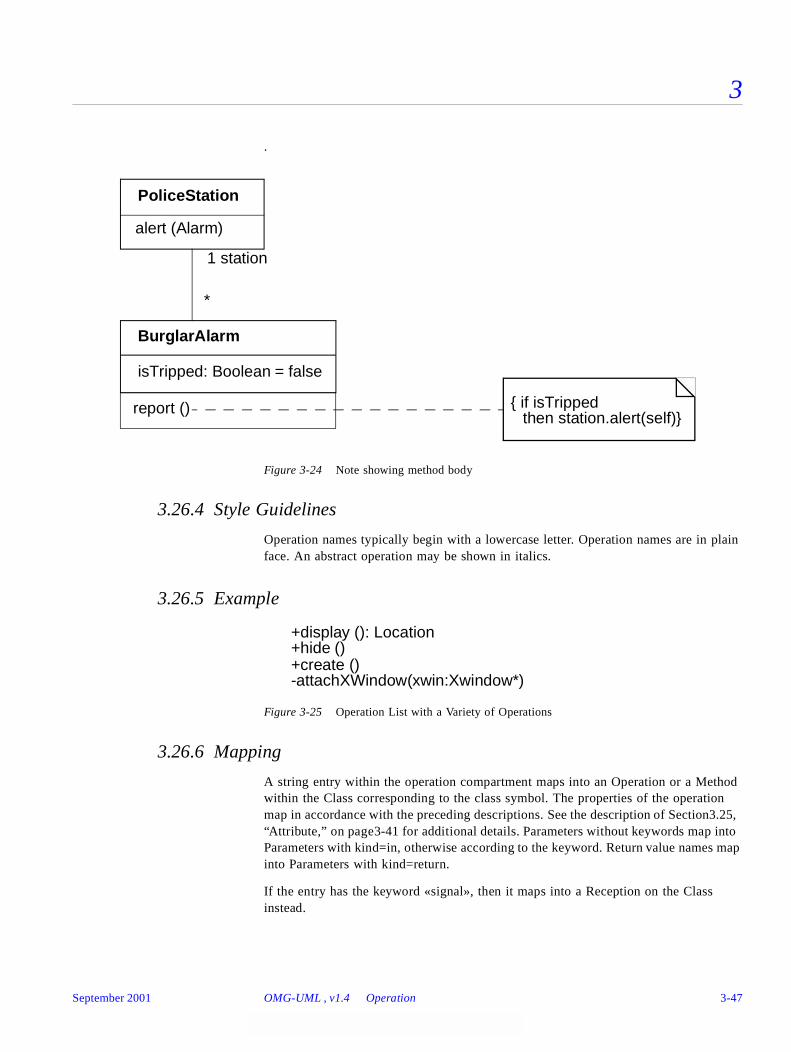
3
.
Figure 3-24 Note showing method body
3.26.4 Style Guidelines
Operation names typically begin with a lowercase letter. Operation names are in plain face. An abstract operation may be shown in italics.
3.26.5 Example
Figure 3-25 Operation List with a Variety of Operations
3.26.6 Mapping
A string entry within the operation compartment maps into an Operation or a Method within the Class corresponding to the class symbol. The properties of the operation map in accordance with the preceding descriptions. See the description of Section3.25, “Attribute,” on page3-41 for additional details. Parameters without keywords map into Parameters with kind=in, otherwise according to the keyword. Return value names map into Parameters with kind=return.
If the entry has the keyword «signal», then it maps into a Reception on the Class instead.
report ()
BurglarAlarm
isTripped: Boolean = false
PoliceStation
1 station
*
{ if isTrippedthen station.alert(self)}
alert (Alarm)
+create ()
+display (): Location+hide ()
-attachXWindow(xwin:Xwindow*)
September 2001 OMG-UML , v1.4 Operation 3-47

3
The topmost appearance of an operation specification in a class hierarchy maps into an Operation definition in the corresponding Class or Interface. Interfaces do not have methods. In a Class, each appearance of an operation entry maps into the presence of a Method in the corresponding Class, unless the operation entry contains the {abstract} property (including use of conventions such as italics for abstract operations). If an abstract operation entry appears within a hierarchy in which the same operation has already been defined in an ancestor, it has no effect but is not an error unless the declarations are inconsistent.
Note that the operation string entry does not specify the body of a method.
3.27 Nested Class Declarations
3.27.1 Semantics
A class declared within another class belongs to the namespace of the other class and may only be used within it. This construct is primarily used for implementation reasons and for information hiding.
3.27.2 Notation
A declaring class and a class in its namespace may be connected by a line, with an “anchor” icon on the end connected to a declaring class (Figure 3-26 on page 3-48). An anchor icon is a cross inside a circle. The contents of the package are declared within the class and belong to its namespace.
3.27.3 Mapping
If Class B is attached to Class A by an “anchor” line with the “anchor” symbol on Class A, then Class B is declared within the Namespace of Class A. That is, the relationship between Class A and Class B is the namespace-ownedElement association.
Figure 3-26 Nested class declaration
DeclaringClass
NestedClass
3-48 OMG-Unified Modeling Language, v1.4 September 2001
3
3.28 Type and Implementation Class
3.28.1 Semantics
Classes can be stereotyped as Types or Implementation Classes (although they can be left undifferentiated as well). A Type is used to specify a domain of objects together with operations applicable to the objects without defining the physical implementation of those objects. A Type may not include any methods, but it may provide behavioral specifications for its operations. It may also have attributes and associations that are defined solely for the purpose of specifying the behavior of the type's operations.
An Implementation Class defines the physical data structure (for attributes and associations) and methods of an object as implemented in traditional languages (C++, Smalltalk, etc.). An Implementation Class is said to realize a Type if it provides all of the operations defined for the Type with the same behavior as specified for the Type’s operations. An Implementation Class may realize a number of different Types.
3.28.2 Notation
An undifferentiated class is shown with no stereotype. A type is shown with the stereotype “«type».” An implementation class is shown with the stereotype “«implementationClass».” A tool is also free to allow a default setting for an entire diagram, in which case all of the class symbols without explicit stereotype indications map into Classes with the default stereotype. This might be useful for a model that is close to the programming level.
The implementation of a type by a class is modeled as the Realization relationship, shown as a dashed line with a solid triangular arrowhead (a dashed “generalization arrow”). This symbol implies the realizing class provides at least all the operations of the Type, with conforming behavior, but it does not imply inheritance of structure (attributes or associations). The generalization hierarchy of a set of classes frequently parallels the generalization hierarchy of a set of types that they realize, but this is not mandatory, as long as each class provides the operations of the types that it realizes.
September 2001 OMG-UML , v1.4 Type and Implementation Class 3-49
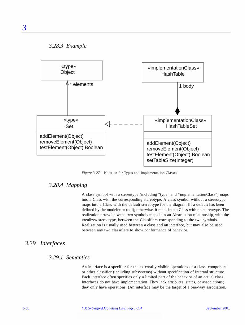
3
3.28.3 Example
Figure 3-27 Notation for Types and Implementation Classes
3.28.4 Mapping
A class symbol with a stereotype (including “type” and “implementationClass”) maps into a Class with the corresponding stereotype. A class symbol without a stereotype maps into a Class with the default stereotype for the diagram (if a default has been defined by the modeler or tool); otherwise, it maps into a Class with no stereotype. The realization arrow between two symbols maps into an Abstraction relationship, with the «realize» stereotype, between the Classifiers corresponding to the two symbols. Realization is usually used between a class and an interface, but may also be used between any two classifiers to show conformance of behavior.
3.29 Interfaces
3.29.1 Semantics
An interface is a specifier for the externally-visible operations of a class, component, or other classifier (including subsystems) without specification of internal structure. Each interface often specifies only a limited part of the behavior of an actual class. Interfaces do not have implementation. They lack attributes, states, or associations; they only have operations. (An interface may be the target of a one-way association,
Set«type»
addElement(Object)removeElement(Object)testElement(Object):Boolean
* elements
Object«type»
HashTableSet«implementationClass»
addElement(Object)removeElement(Object)testElement(Object):Boolean
1 body
HashTable«implementationClass»
setTableSize(Integer)
3-50 OMG-Unified Modeling Language, v1.4 September 2001

3
however, but it may not have an association that it can navigate.) Interfaces may have generalization relationships. An interface is formally equivalent to an abstract class with no attributes and no methods and only abstract operations, but Interface is a peer of Class within the UML metamodel (both are Classifiers).
3.29.2 Notation
An interface is a Classifier and may be shown using the full rectangle symbol with compartments and the keyword «interface». A list of operations supported by the interface is placed in the operation compartment. The attribute compartment may be omitted because it is always empty.
An interface may also be displayed as a small circle with the name of the interface placed below the symbol. The circle may be attached by a solid line to classifiers that support it. This indicates that the class provides all of the operations in the interface type (and possibly more). The operations provided are not shown on the circle notation; use the full rectangle symbol to show the list of operations. A class that uses or requires the operations supplied by the interface may be attached to the circle by a dashed arrow pointing to the circle. The dashed arrow implies that the class requires no more than the operations specified in the interface; the client class is not required to actually use all of the interface operations.
The Realization relationship from a classifier to an interface that it supports is shown by a dashed line with a solid triangular arrowhead (a “dashed generalization symbol”). This is the same notation used to indicate realization of a type by an implementation class. In fact, this symbol can be used between any two classifier symbols, with the meaning that the client (the one at the tail of the arrow) supports at least all of the operations defined in the supplier (the one at the head of the arrow), but with no necessity to support any of the data structure of the supplier (attributes and associations).
3.29.3 Example
Figure 3-28 Shorthand Version of Interface Notation
+c re ate ()+ log in(U se rN a m e , P assw d )+find (S tore Id)+g etPO S tota ls (PO S id )+u pd ateS tore Tota ls (Id ,Sales )+g et(Ite m )
-s toreId : In te ger-P O S list: L ist
Store
PO Ste rm ina l
PO Ste rm ina lH o m e
<< use> >
Store H om e
Store
POSterminal
September 2001 OMG-UML , v1.4 Interfaces 3-51
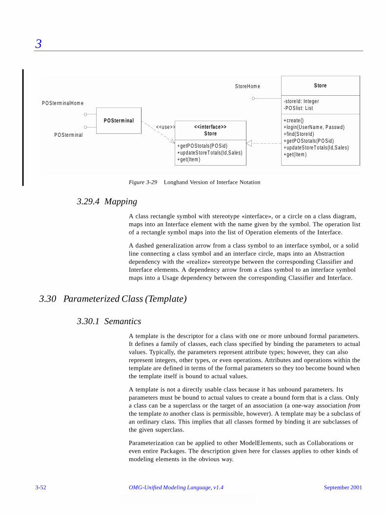
3
Figure 3-29 Longhand Version of Interface Notation
3.29.4 Mapping
A class rectangle symbol with stereotype «interface», or a circle on a class diagram, maps into an Interface element with the name given by the symbol. The operation list of a rectangle symbol maps into the list of Operation elements of the Interface.
A dashed generalization arrow from a class symbol to an interface symbol, or a solid line connecting a class symbol and an interface circle, maps into an Abstraction dependency with the «realize» stereotype between the corresponding Classifier and Interface elements. A dependency arrow from a class symbol to an interface symbol maps into a Usage dependency between the corresponding Classifier and Interface.
3.30 Parameterized Class (Template)
3.30.1 Semantics
A template is the descriptor for a class with one or more unbound formal parameters. It defines a family of classes, each class specified by binding the parameters to actual values. Typically, the parameters represent attribute types; however, they can also represent integers, other types, or even operations. Attributes and operations within the template are defined in terms of the formal parameters so they too become bound when the template itself is bound to actual values.
A template is not a directly usable class because it has unbound parameters. Its parameters must be bound to actual values to create a bound form that is a class. Only a class can be a superclass or the target of an association (a one-way association from the template to another class is permissible, however). A template may be a subclass of an ordinary class. This implies that all classes formed by binding it are subclasses of the given superclass.
Parameterization can be applied to other ModelElements, such as Collaborations or even entire Packages. The description given here for classes applies to other kinds of modeling elements in the obvious way.
+ crea te ()+ login(U se rN am e, P assw d)+ find(S tore Id )+ ge tP O Sto ta ls (P O S id )+ upda teS to reT o tals (Id,S a les)+ ge t(Item )
-s to re Id : In tege r-P O S lis t: L is t
S tore
P O Ste rm inal
P O Ste rm inalH om e
< <use> >
S toreH om e
P O Sterm inal
+ ge tP O Sto ta ls (P O S id )+ upda teS to reT o tals (Id,S a les)+ ge t(Item )
<<interface>>S tore
3-52 OMG-Unified Modeling Language, v1.4 September 2001
3
3.30.2 Notation
A small dashed rectangle is superimposed on the upper right-hand corner of the rectangle for the class (or to the symbol for another modeling element). The dashed rectangle contains a parameter list of formal parameters for the class and their implementation types. The list must not be empty, although it might be suppressed in the presentation. The name, attributes, and operations of the parameterized class appear as normal in the class rectangle; however, they may also include occurrences of the formal parameters. Occurrences of the formal parameters can also occur inside of a context for the class, for example, to show a related class identified by one of the parameters.
3.30.3 Presentation Options
The parameter list may be comma-separated or it may be one per line.
Parameters are restricted attributes, shown as strings with the syntax:
name : type = default-value
• Where name is an identifier for the parameter with scope inside the template.
• Where type is a string designating a Classifier for the parameter. If it is a simple word, it must be the name of a Classifier. Otherwise it is a programming-language dependent string that maps into a ProgrammingLanguageDataType according to the programming language (if any) for the diagram context or specified in a support tool.
• Where default-value is a string designating an Expression for a default value that is used when the corresponding argument is omitted in a Binding. The equal sign and expression may be omitted, in which case there is no default value and the argument must be supplied in a Binding.
If the type name is omitted, the parameter type is assumed to be Classifier. The value supplied for an argument in a Binding must be the name of a Classifier (including a class or a data type). Other parameter types (such as Integer) must be explicitly shown. The value supplied for an argument in a Binding must be an actual instance value of the given kind.
September 2001 OMG-UML , v1.4 Parameterized Class (Template) 3-53
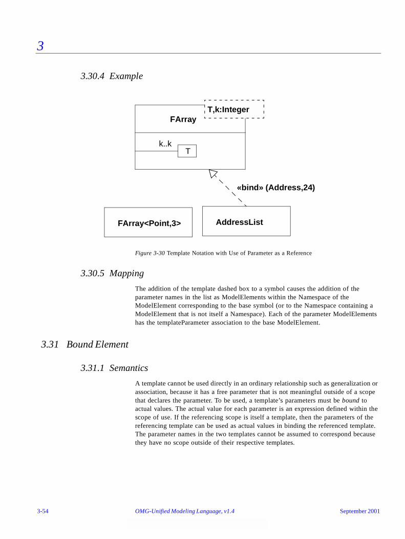
3
3.30.4 Example
Figure 3-30 Template Notation with Use of Parameter as a Reference
3.30.5 Mapping
The addition of the template dashed box to a symbol causes the addition of the parameter names in the list as ModelElements within the Namespace of the ModelElement corresponding to the base symbol (or to the Namespace containing a ModelElement that is not itself a Namespace). Each of the parameter ModelElements has the templateParameter association to the base ModelElement.
3.31 Bound Element
3.31.1 Semantics
A template cannot be used directly in an ordinary relationship such as generalization or association, because it has a free parameter that is not meaningful outside of a scope that declares the parameter. To be used, a template’s parameters must be bound to actual values. The actual value for each parameter is an expression defined within the scope of use. If the referencing scope is itself a template, then the parameters of the referencing template can be used as actual values in binding the referenced template. The parameter names in the two templates cannot be assumed to correspond because they have no scope outside of their respective templates.
FArray
FArray<Point,3>
T,k:Integer
«bind» (Address,24)
Tk..k
AddressList
3-54 OMG-Unified Modeling Language, v1.4 September 2001

3
3.31.2 Notation
A bound element is indicated by a text syntax in the name string of an element, as follows:
Template-name ‘<‘ value-list ‘>’
• Where value-list is a comma-delimited non-empty list of value expressions.
• Where Template-name is identical to the name of a template.
For example, VArray<Point,3> designates a class described by the template Varray.
The number and type of values must match the number and type of the template parameters for the template of the given name.
The bound element name may be used anywhere that an element name of the parameterized kind could be used. For example, a bound class name could be used within a class symbol on a class diagram, as an attribute type, or as part of an operation signature.
Note that a bound element is fully specified by its template; therefore, its content may not be extended. Declaration of new attributes or operations for classes is not permitted, for example, but a bound class could be subclassed and the subclass extended in the usual way.
The relationship between the bound element and its template alternatively may be shown by a Dependency relationship with the keyword «bind». The arguments are shown in parentheses after the keyword. In this case, the bound form may be given a name distinct from the template.
3.31.3 Style Guidelines
The attribute and operation compartments are normally suppressed within a bound class, because they must not be modified in a bound template.
3.31.4 Example
See Figure 3-30 on page 3-54.
3.31.5 Mapping
The use of the bound element syntax for the name of a symbol maps into a Binding dependency between the dependent ModelElement (such as Class) corresponding to the bound element symbol and the provider ModelElement (again, such as Class) whose name matches the name part of the bound element without the arguments. If the name does not match a template element or if the number of arguments in the bound element does not match the number of parameters in the template, then the model is ill formed. Each argument position in the bound element maps into a TemplateArgument bearing a binding link to the Binding dependency and a modelElement link to the
September 2001 OMG-UML , v1.4 Bound Element 3-55

3
ModelElement that is implicitly substituted for the template parameter in the corresponding position in the template definition. An explicitly drawn «bind» dependency symbol mays to a Binding dependency with arguments as described above.
3.32 Utility
A utility is a grouping of global variables and procedures in the form of a class declaration. This is not a fundamental construct, but a programming convenience. The attributes and operations of the utility become global variables and procedures. A utility is modeled as a stereotype of a classifier.
3.32.1 Semantics
The instance-scope attributes and operations of a utility are interpreted as global attributes and operations. It is inappropriate for a utility to declare class-scope attributes and operations because the instance-scope members are already interpreted as being at class scope.
3.32.2 Notation
A utility is shown as the stereotype «utility» of Class. It may have both attributes and operations, all of which are treated as global attributes and operations.
3.32.3 Example
Figure 3-31 Notation for Utility
3.32.4 Mapping
This is not a special symbol. It simply maps into a Class element with the «utility» stereotype.
MathPak«utility»
sin (Angle): Real
sqrt (Real): Realrandom(): Real
cos (Angle): Real
3-56 OMG-Unified Modeling Language, v1.4 September 2001

3
3.33 Metaclass
3.33.1 Semantics
A metaclass is a class whose instances are classes.
3.33.2 Notation
A metaclass is shown as the stereotype «metaclass» of Class.
3.33.3 Mapping
This is not a special symbol. It simply maps into a Class element with the «metaclass» stereotype.
3.34 Enumeration
3.34.1 Semantics
An Enumeration is a user-defined data type whose instances are a set of user-specified named enumeration literals. The literals have a relative order but no algebra is defined on them.
3.34.2 Notation
An Enumeration is shown using the Classifier notation (a rectangle) with the keyword «enumeration». The name of the Enumeration is placed in the upper compartment. An ordered list of enumeration literals may be placed, one to a line, in the middle compartment. Operations defined on the literals may be placed in the lower compartment. The lower and middle compartments may be suppressed.
3.34.3 Mapping
Maps into an Enumeration with the given list of enumeration literals.
3.35 Stereotype Declaration
3.35.1 Semantics
A Stereotype is a user-defined metaelement whose structure matches an existing UML metaelement (its “base class”). Because it is user defined, a stereotype declaration is an element that appears at the “model” layer of the UML four-layer metamodeling hierarchy although it conceptually belongs in the layer below, the metamodel layer.
September 2001 OMG-UML , v1.4 Metaclass 3-57

3
3.35.2 Notation
Because stereotypes span two different metamodeling layers, a special notation is required to clearly indicate the crossover between the two layers. Specifically, it is necessary to show how a model-level element (the stereotype) relates to its metaelement (its UML base class). This is denoted using a special stereotype of Dependency called «stereotype» as shown in Figure 3-32 on page 3-59.
The Stereotype itself is shown using the Classifier notation (a rectangle) with the keyword «stereotype» (Figure 3-32). The name of the Stereotype is placed in the upper compartment. Constraints on elements described by the stereotype may be placed in a named compartment called Constraints. Required tags may be placed in a named compartment called Tags. Individual items (tags) in the list of are defined according to the following format:
tagDefinitionName : String [multiplicity]
where string can be either a string matching the name of a data type representing the type of the values of the tag, or it is a reference to a metaclass or a stereotype. In the latter case, the string has the form:
«metaclass» metaclassName
or
«stereotype» stereotypeName
where metaclassName is the name of the referenced metaclass and is the name of the references stereotype. The multiplicity element is optional and conforms to standard rules for specifying multiplicities. In case of a range specification, a lower bound of zero indicates an optional tag.
3-58 OMG-Unified Modeling Language, v1.4 September 2001

3
Figure 3-32 Notational form for declaring a stereotype
In the example diagram in Figure 3-32, the stereotype Persistent is a stereotype of the UML metaelement Class. TableName is an optional tag whose type is a model type called String while SQLFile is a reference to an instance of Component in the model.
An icon can be defined for the stereotype, but its graphical definition is outside the scope of UML and must be handled by an editing tool.
An alternative and usually more compact way of specifying stereotypes and tags using tables is shown in Figure 3-33 and Figure 3-34, respectively.
Figure 3-33 Tabular form for specifying stereotypes
Figure 3-34 Tabular form for specifying tags
Stereotype Base Class Parent Tags Constraints Description
ArchitecturalElement
GeneralizableElement
N/A N/A N/A A generic stereotype that is the parent of all other stereotypes used for archi-tectural modeling .
Capsule Class ArchitecturalElement
isDynamic self.isActive = true Indicates a class that is used to model the structural components of an archi-tecture specification.
Tag Stereotype Type Multiplicity Description
isDynamic Capsule UML::Datatypes::Boolean 1 Used to identify if the associated capsule class may be created and destroyed dynamically.
Class«metaclass»
«stereotype»
Constraints{TableName should not be longer than 8 characters}
«stereotype»Persistent
Tags
SQLFile : «metaclass» ComponentTableName : String [0..1]
September 2001 OMG-UML , v1.4 Stereotype Declaration 3-59
3
Each row of the stereotype specification table in Figure 3-33 defines one stereotype and each row in the tag specification table in Figure 3-34 contains one tag definition.
The columns of the stereotype specification table are defined as follows:
• Stereotype - the name of the stereotype.
• Base Class - the UML metamodel element that serves as the base for the stereotype.
• Parent - the direct parent of the stereotype being defined (NB: if one exists, otherwise the symbol “N/A” is used).
• Tags - a list of all tags of the tagged values that may be associated with this stereotype (or N/A if none are defined).
• Constraints - a list of constraints associated with the stereotype.
• Description - an informal description with possible explanatory comments.
The columns of the tag specification table are defined as follows:
• Tag - the name of the tag.
• Stereotype - the name of the stereotype which owns this tag, or “N/A” if it is a stand alone tag.
• Type - the name of the type of the values that can be associated with the tag.
• Multiplicity - the maximum number of values that may be associated with one tag instance.
• Description - an informal description with possible explanatory comments.
In the case of both the stereotype specification table and the tag specification table, columns that are not applicable may be omitted.
In the example stereotype specification table of Figure 3-34, two related stereotypes are defined. The first row declares the stereotype ArchitecturalElement, which is a stereotype of GeneralizableElement, while the second row declares the stereotype Capsule, which is a specialization of the ArchitecturalElement stereotype, but which applies only to instances of Class, which is a subclass of GeneralizableElement in the metamodel.
3-60 OMG-Unified Modeling Language, v1.4 September 2001
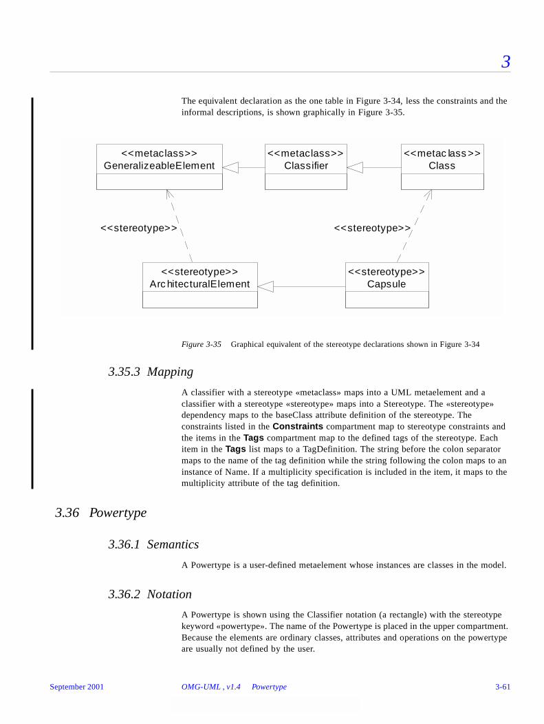
3
The equivalent declaration as the one table in Figure 3-34, less the constraints and the informal descriptions, is shown graphically in Figure 3-35.
Figure 3-35 Graphical equivalent of the stereotype declarations shown in Figure 3-34
3.35.3 Mapping
A classifier with a stereotype «metaclass» maps into a UML metaelement and a classifier with a stereotype «stereotype» maps into a Stereotype. The «stereotype» dependency maps to the baseClass attribute definition of the stereotype. The constraints listed in the Constraints compartment map to stereotype constraints and the items in the Tags compartment map to the defined tags of the stereotype. Each item in the Tags list maps to a TagDefinition. The string before the colon separator maps to the name of the tag definition while the string following the colon maps to an instance of Name. If a multiplicity specification is included in the item, it maps to the multiplicity attribute of the tag definition.
3.36 Powertype
3.36.1 Semantics
A Powertype is a user-defined metaelement whose instances are classes in the model.
3.36.2 Notation
A Powertype is shown using the Classifier notation (a rectangle) with the stereotype keyword «powertype». The name of the Powertype is placed in the upper compartment. Because the elements are ordinary classes, attributes and operations on the powertype are usually not defined by the user.
GeneralizeableElement<<metaclass>>
Classifier<<metaclass>>
Class<<metac lass >>
Arc hitecturalElement<<stereotype>>
Capsule<<stereotype>>
<<stereotype>> <<stereotype>>
September 2001 OMG-UML , v1.4 Powertype 3-61
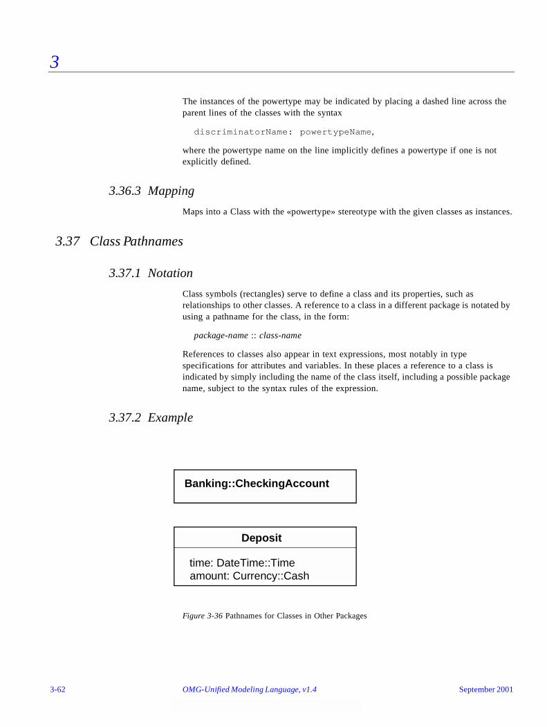
3
The instances of the powertype may be indicated by placing a dashed line across the parent lines of the classes with the syntax
discriminatorName: powertypeName,
where the powertype name on the line implicitly defines a powertype if one is not explicitly defined.
3.36.3 Mapping
Maps into a Class with the «powertype» stereotype with the given classes as instances.
3.37 Class Pathnames
3.37.1 Notation
Class symbols (rectangles) serve to define a class and its properties, such as relationships to other classes. A reference to a class in a different package is notated by using a pathname for the class, in the form:
package-name :: class-name
References to classes also appear in text expressions, most notably in type specifications for attributes and variables. In these places a reference to a class is indicated by simply including the name of the class itself, including a possible package name, subject to the syntax rules of the expression.
3.37.2 Example
Figure 3-36 Pathnames for Classes in Other Packages
Banking::CheckingAccount
Deposit
time: DateTime::Timeamount: Currency::Cash
3-62 OMG-Unified Modeling Language, v1.4 September 2001
3
3.37.3 Mapping
A class symbol whose name string is a pathname represents a reference to the Class with the given name inside the package with the given name. The name is assumed to be defined in the target package; otherwise, the model is ill formed. A Relationship from a symbol in the current package; that is, the package containing the diagram and its mapped elements to a symbol in another package is part of the current package.
3.38 Accessing or Importing a Package
3.38.1 Semantics
An element may reference an element contained in a different package. On the package level, the «access» dependency indicates that the contents of the target package may be referenced by the client package or packages recursively embedded within it. The target references must have visibility sufficient for the referents: public visibility for an unrelated package, public or protected visibility for a descendant of the target package, or any visibility for a package nested inside the target package (an access dependency is not required for the latter case). A package nested inside the package making the access gets the same access.
Note that an access dependency does not modify the namespace of the client or in any other way automatically create references; it merely grants permission to establish references. Note also that a tool could automatically create access dependencies for users if desired when references are created.
An import dependency grants access and also loads the names with appropriate visibility in the target namespace into the accessing package; that is, a pathname is not necessary to reference them. Such names are not automatically re-exported, however; a name must be explicitly re-exported (and may be given a new name and visibility at the same time).
3.38.2 Notation
The access dependency is displayed as a dependency arrow from the referencing (client) package to the target (supplier) package containing the target of the references. The arrow has the stereotype keyword «access». This dependency indicates that elements within the client package may legally reference elements within the supplier. The references must also satisfy visibility constraints specified by the supplier. Note that the dependency does not automatically create any references. It merely grants permission for them to be established.
The import dependency has the same notation as the access dependency except it has the stereotype keyword «import».
September 2001 OMG-UML , v1.4 Accessing or Importing a Package 3-63
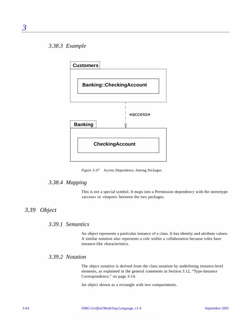
3
3.38.3 Example
Figure 3-37 Access Dependency Among Packages
3.38.4 Mapping
This is not a special symbol. It maps into a Permission dependency with the stereotype «access» or «import» between the two packages.
3.39 Object
3.39.1 Semantics
An object represents a particular instance of a class. It has identity and attribute values. A similar notation also represents a role within a collaboration because roles have instance-like characteristics.
3.39.2 Notation
The object notation is derived from the class notation by underlining instance-level elements, as explained in the general comments in Section 3.12, “Type-Instance Correspondence,” on page 3-14.
An object shown as a rectangle with two compartments.
Banking::CheckingAccount
CheckingAccount
Banking
«access»
Customers
3-64 OMG-Unified Modeling Language, v1.4 September 2001
3
The top compartment shows the name of the object and its class, all underlined, using the syntax:
objectname : classname
The classname can include a full pathname of enclosing package, if necessary. The package names precede the classname and are separated by double colons. For example:
display_window: WindowingSystem::GraphicWindows::Window
A stereotype for the class may be shown textually (in guillemets above the name string) or as an icon in the upper right corner. The stereotype for an object must match the stereotype for its class.
To show multiple classes that the object is an instance of, use a comma-separated list of classnames. These classnames must be legal for multiple classification; that is, only one implementation class permitted, but multiple types permitted.
To show the presence of an object in a particular state of a class, use the syntax:
objectname : classname ‘[‘ statename-list ‘]’
The list must be a comma-separated list of names of states that can legally occur concurrently.
The second compartment shows the attributes for the object and their values as a list. Each value line has the syntax:
attributename : type = value
The type is redundant with the attribute declaration in the class and may be omitted.
The value is specified as a literal value. UML does not specify the syntax for literal value expressions; however, it is expected that a tool will specify such a syntax using some programming language.
The flow relationship between two values of the same object over time can be shown by connecting two object symbols by a dashed arrow with the keyword «become». If the flow arrow is on a collaboration diagram, the label may also include a sequence number to show when the value changes. Similarly, the keyword «copy» can be used to show the creation of one object from another object value.
3.39.3 Presentation Options
The name of the object may be omitted. In this case, the colon should be kept with the class name. This represents an anonymous object of the given class given identity by its relationships.
The class of the object may be suppressed (together with the colon).
The attribute value compartment as a whole may be suppressed.
Attributes whose values are not of interest may be suppressed.
September 2001 OMG-UML , v1.4 Object 3-65

3
Attributes whose values change during a computation may show their values as a list of values held over time. In an interactive tool, they might even change dynamically. An alternate notation is to show the same object more than once with a «becomes» relationship between them.
3.39.4 Style Guidelines
Objects may be shown on class diagrams. The elements on collaboration diagrams are not objects, because they describe many possible objects. They are instead roles that may be held by object. Objects in class diagrams serve mainly to show examples of data structures.
3.39.5 Variations
For a language such as Self in which operations can be attached to individual objects at run time, a third compartment containing operations would be appropriate as a language-specific extension.
3.39.6 Example
Figure 3-38 Objects
3.39.7 Mapping
In an object diagram, or within an ordinary class diagram, an object symbol maps into an Object of the Class (or Classes) given by the classname part of the name string. The attribute list in the symbol maps into a set of AttributeLinks attached to the Object, with values given by the value expressions in the attribute list in the symbol. If a list of states in brackets follows the class name, then this maps into a ClassifierInState with the named Class as its type and the named States as the states. The ClassfierInState classifies the Object.
triangle: Polygon
center = (0,0)vertices = ((0,0),(4,0),(4,3))borderColor = blackfillColor = white
triangle: Polygon
triangle
:Polygon
scheduler
3-66 OMG-Unified Modeling Language, v1.4 September 2001
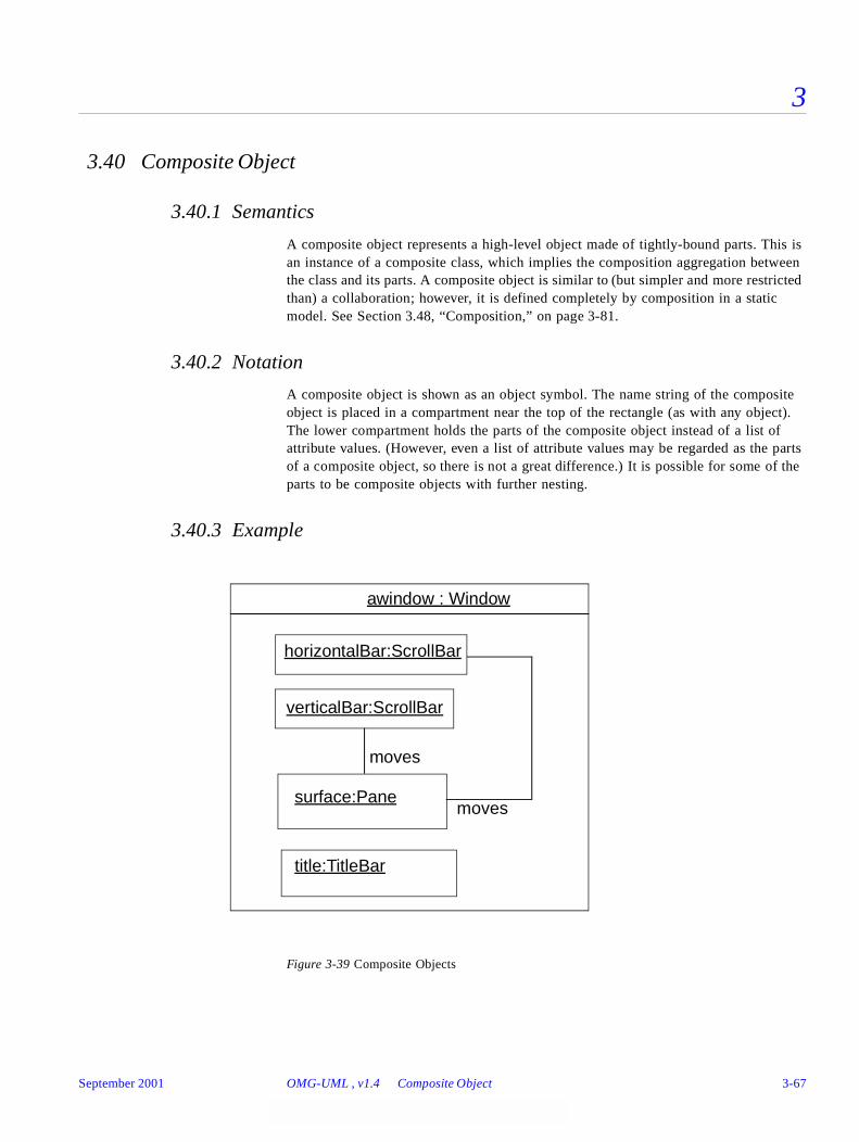
3
3.40 Composite Object
3.40.1 Semantics
A composite object represents a high-level object made of tightly-bound parts. This is an instance of a composite class, which implies the composition aggregation between the class and its parts. A composite object is similar to (but simpler and more restricted than) a collaboration; however, it is defined completely by composition in a static model. See Section 3.48, “Composition,” on page 3-81.
3.40.2 Notation
A composite object is shown as an object symbol. The name string of the composite object is placed in a compartment near the top of the rectangle (as with any object). The lower compartment holds the parts of the composite object instead of a list of attribute values. (However, even a list of attribute values may be regarded as the parts of a composite object, so there is not a great difference.) It is possible for some of the parts to be composite objects with further nesting.
3.40.3 Example
Figure 3-39 Composite Objects
horizontalBar:ScrollBar
verticalBar:ScrollBar
awindow : Window
surface:Pane
title:TitleBar
moves
moves
September 2001 OMG-UML , v1.4 Composite Object 3-67
3
3.40.4 Mapping
A composite object symbol maps into an Object of the given Class with composition links to each of the Objects and Links corresponding to the class box symbols and to association path symbols directly contained within the boundary of the composite object symbol (and not contained within another deeper boundary).
3.41 Association
Binary associations are shown as lines connecting two classifier symbols. The lines may have a variety of adornments to show their properties. Ternary and higher-order associations are shown as diamonds connected to class symbols by lines.
3.42 Binary Association
3.42.1 Semantics
A binary association is an association among exactly two classifiers (including the possibility of an association from a classifier to itself).
3.42.2 Notation
A binary association is drawn as a solid path connecting two classifier symbols (both ends may be connected to the same classifier, but the two ends are distinct). The path may consist of one or more connected segments. The individual segments have no semantic significance, but may be graphically meaningful to a tool in dragging or resizing an association symbol. A connected sequence of segments is called a path.
In a binary association, both ends may attach to the same classifier. The links of such an association may connect two different instances from the same classifier or one instance to itself. The latter case may be forbidden by a constraint if necessary.
The end of an association where it connects to a classifier is called an association end. Most of the interesting information about an association is attached to its ends.
The path may also have graphical adornments attached to the main part of the path itself. These adornments indicate properties of the entire association. They may be dragged along a segment or across segments, but must remain attached to the path. It is a tool responsibility to determine how close association adornments may approach an end so that confusion does not occur. The following kinds of adornments may be attached to a path.
3.42.2.1 association name
Designates the (optional) name of the association.
3-68 OMG-Unified Modeling Language, v1.4 September 2001
3
It is shown as a name string near the path (but not near enough to an end to be confused with a rolename). The name string may have an optional small black solid triangle in it. The point of the triangle indicates the direction in which to read the name. The name-direction arrow has no semantics significance, it is purely descriptive. The classifiers in the association are ordered as indicated by the name-direction arrow.
Note – There is no need for a name direction property on the association model; the ordering of the classifiers within the association is the name direction. This convention works even with n-ary associations.
A stereotype keyword within guillemets may be placed above or in front of the association name. A property string may be placed after or below the association name.
3.42.2.2 association class symbol
Designates an association that has class-like properties, such as attributes, operations, and other associations. This is present if, and only if, the association is an association class. It is shown as a class symbol attached to the association path by a dashed line.
The association path and the association class symbol represent the same underlying model element, which has a single name. The name may be placed on the path, in the class symbol, or on both (but they must be the same name).
Logically, the association class and the association are the same semantic entity; however, they are graphically distinct. The association class symbol can be dragged away from the line, but the dashed line must remain attached to both the path and the class symbol.
3.42.3 Presentation Options
When two paths cross, the crossing may optionally be shown with a small semicircular jog to indicate that the paths do not intersect (as in electrical circuit diagrams).
3.42.4 Style Guidelines
Lines may be drawn using various styles, including orthogonal segments, oblique segments, and curved segments. The choice of a particular set of line styles is a user choice.
3.42.5 Options
3.42.5.1 Xor-association
An xor-constraint indicates a situation in which only one of several potential associations may be instantiated at one time for any single instance. This is shown as a dashed line connecting two or more associations, all of which must have a classifier in
September 2001 OMG-UML , v1.4 Binary Association 3-69
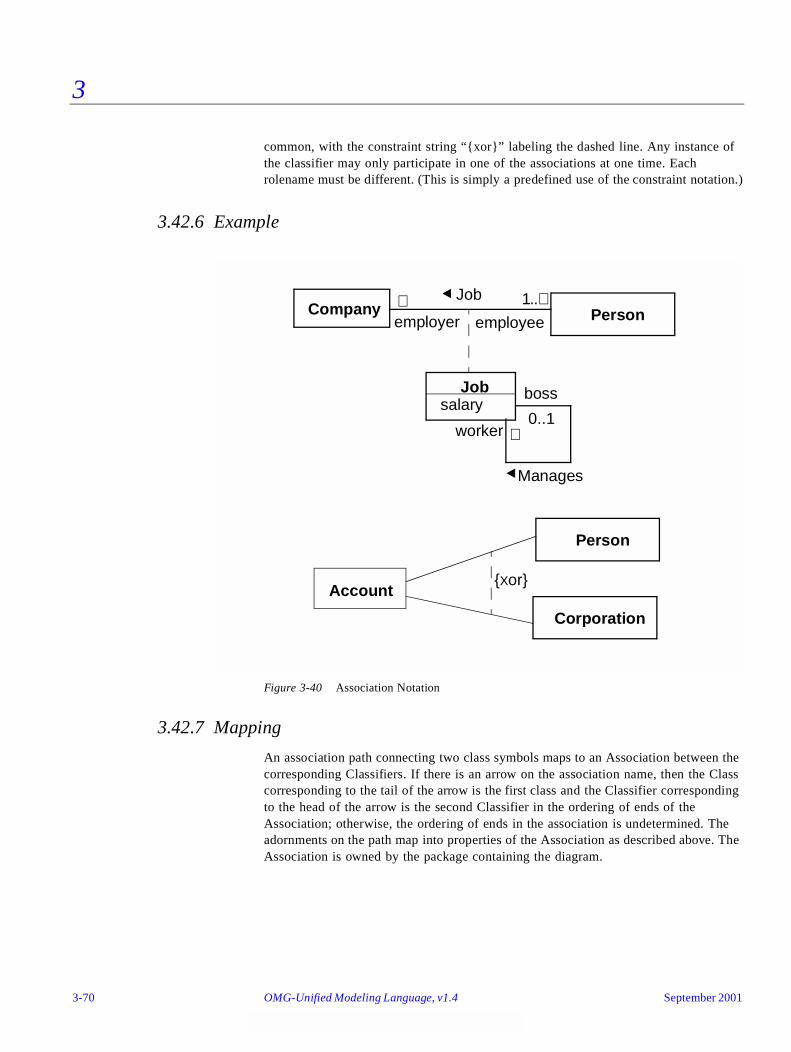
3
common, with the constraint string “{xor}” labeling the dashed line. Any instance of the classifier may only participate in one of the associations at one time. Each rolename must be different. (This is simply a predefined use of the constraint notation.)
3.42.6 Example
Figure 3-40 Association Notation
3.42.7 Mapping
An association path connecting two class symbols maps to an Association between the corresponding Classifiers. If there is an arrow on the association name, then the Class corresponding to the tail of the arrow is the first class and the Classifier corresponding to the head of the arrow is the second Classifier in the ordering of ends of the Association; otherwise, the ordering of ends in the association is undetermined. The adornments on the path map into properties of the Association as described above. The Association is owned by the package containing the diagram.
Person
Manages
JobCompany
boss
worker
employeeemployer1..∗
∗
∗
0..1
Job
Account
Person
Corporation
{Xor}
salary
3-70 OMG-Unified Modeling Language, v1.4 September 2001
3
3.43 Association End
3.43.1 Semantics
An association end is simply an end of an association where it connects to a classifier. It is part of the association, not part of the classifier. Each association has two or more ends. Most of the interesting details about an association are attached to its ends. An association end is not a separable element, it is just a mechanical part of an association.
3.43.2 Notation
The path may have graphical adornments at each end where the path connects to the classifier symbol. These adornments indicate properties of the association related to the classifier. The adornments are part of the association symbol, not part of the classifier symbol. The end adornments are either attached to the end of the line, or near the end of the line, and must drag with it. The following kinds of adornments may be attached to an association end.
3.43.2.1 multiplicity
Specified by a text syntax. Multiplicity may be suppressed on a particular association or for an entire diagram. In an incomplete model the multiplicity may be unspecified in the model itself. In this case, it must be suppressed in the notation. See Section 3.44, “Multiplicity,” on page 3-75.
3.43.2.2 ordering
If the multiplicity is greater than one, then the set of related elements can be ordered or unordered. If no indication is given, then it is unordered (the elements form a set). Various kinds of ordering can be specified as a constraint on the association end. The declaration does not specify how the ordering is established or maintained. Operations that insert new elements must make provision for specifying their position either implicitly (such as at the end) or explicitly. Possible values include:
• unordered - the elements form an unordered set. This is the default and need not be shown explicitly.
• ordered - the elements of the set have an ordering, but duplicates are still prohibited. This generic specification includes all kinds of ordering. This may be specified by the keyword syntax “{ordered}.”
An ordered relationship may be implemented in various ways; however, this is normally specified as a language-specified code generation property to select a particular implementation. An implementation extension might substitute the data structure to hold the elements for the generic specification “ordered.”
At implementation level, sorting may also be specified. It does not add new semantic information, but it expresses a design decision:
September 2001 OMG-UML , v1.4 Association End 3-71
3
• sorted - the elements are sorted based on their internal values. The actual sorting rule is best specified as a separate constraint.
3.43.2.3 qualifier
A qualifier is optional, but not suppressible. See Section 3.45, “Qualifier,” on page 3-76.
3.43.2.4 navigability
An arrow may be attached to the end of the path to indicate that navigation is supported toward the classifier attached to the arrow. Arrows may be attached to zero, one, or two ends of the path. To be totally explicit, arrows may be shown whenever navigation is supported in a given direction. In practice, it is often convenient to suppress some of the arrows and just show exceptional situations. See Section 3.22.3, “Presentation Options,” on page 3-36 for details.
3.43.2.5 aggregation indicator
A hollow diamond is attached to the end of the path to indicate aggregation. The diamond may not be attached to both ends of a line, but it need not be present at all. The diamond is attached to the class that is the aggregate. The aggregation is optional, but not suppressible.
If the diamond is filled, then it signifies the strong form of aggregation known as composition. See Section 3.48, “Composition,” on page 3-81.
3.43.2.6 rolename
A name string near the end of the path. It indicates the role played by the class attached to the end of the path near the rolename. The rolename is optional, but not suppressible.
3.43.2.7 interface specifier
The name of a Classifier with the syntax:
‘:’ classifiername, . . .
It indicates the behavior expected of an associated object by the related instance. In other words, the interface specifier specifies the behavior required to enable the association. In this case, the actual classifier usually provides more functionality than required for the particular association (since it may have other responsibilities).
The use of a rolename and interface specifier are equivalent to creating a small collaboration that includes just an association and two roles, whose structure is defined by the rolename and attached classifier on the original association. Therefore, the
3-72 OMG-Unified Modeling Language, v1.4 September 2001
3
original association and classifiers are a use of the collaboration. The original classifier must be compatible with the interface specifier (which can be an interface or a type, among other kinds of classifiers).
If an interface specifier is omitted, then the association may be used to obtain full access to the associated class.
3.43.2.8 changeability
If the links are changeable (can be added, deleted, and moved), then no indicator is needed. The property {frozen} indicates that no links may be added, deleted, or moved from an object (toward the end with the adornment) after the object is created and initialized. The property {addOnly} indicates that additional links may be added (presumably, the multiplicity is variable); however, links may not be modified or deleted.
3.43.2.9 visibility
Specified by a visibility indicator (‘+’, ‘#’, ‘-’ or explicit property name such as {public}) in front of the rolename. Specifies the visibility of the association traversing in the direction toward the given rolename. See Section 3.25, “Attribute,” on page 3-41 for details of visibility specification.
Other properties can be specified for association ends, but there is no graphical syntax for them. To specify such properties, use the constraint syntax near the end of the association path (a text string in braces). Examples of other properties include mutability.
3.43.3 Presentation Options
If there are two or more aggregations to the same aggregate, they may be drawn as a tree by merging the aggregation end into a single segment. This requires that all of the adornments on the aggregation ends be consistent. This is purely a presentation option, there are no additional semantics to it.
Various options are possible for showing the navigation arrows on a diagram. These can vary from time to time by user request or from diagram to diagram.
• Presentation option 1: Show all arrows. The absence of an arrow indicates navigation is not supported.
• Presentation option 2: Suppress all arrows. No inference can be drawn about navigation. This is similar to any situation in which information is suppressed from a view.
• Presentation option 3: Suppress arrows for associations with navigability in both directions, show arrows only for associations with one-way navigability. In this case, the two-way navigability cannot be distinguished from no-way navigation; however, the latter case is normally rare or nonexistent in practice. This is yet another example of a situation in which some information is suppressed from a view.
September 2001 OMG-UML , v1.4 Association End 3-73

3
3.43.4 Style Guidelines
If there are multiple adornments on a single association end, they are presented in the following order, reading from the end of the path attached to the classifier toward the bulk of the path:
• qualifier
• aggregation symbol
• navigation arrow
Rolenames and multiplicity should be placed near the end of the path so that they are not confused with a different association. They may be placed on either side of the line. It is tempting to specify that they will always be placed on a given side of the line (clockwise or counterclockwise), but this is sometimes overridden by the need for clarity in a crowded layout. A rolename and a multiplicity may be placed on opposite sides of the same association end, or they may be placed together (for example, “* employee”).
3.43.5 Example
Figure 3-41 Various Adornments on Association Roles
3.43.6 Mapping
The adornments on the end of an association path map into properties of the corresponding role of the Association. In general, implications cannot be drawn from the absence of an adornment (it may simply be suppressed) but see the preceding descriptions for details. The interface specifier maps into the “specification” rolename in the AssociationEnd-Classifier association.
Polygon PointContains
{ordered}
3..∗1
GraphicsBundle
colortexturedensity
1
1
-bundle
+vertex
3-74 OMG-Unified Modeling Language, v1.4 September 2001
3
3.44 Multiplicity
3.44.1 Semantics
A multiplicity item specifies the range of allowable cardinalities that a set may assume. Multiplicity specifications may be given for roles within associations, parts within composites, repetitions, and other purposes. Essentially a multiplicity specification is a subset of the open set of nonnegative integers.
3.44.2 Notation
A multiplicity specification is shown as a text string comprising a comma-separated sequence of integer intervals, where an interval represents a (possibly infinite) range of integers, in the format:
lower-bound .. upper-bound
where lower-bound and upper-bound are literal integer values, specifying the closed (inclusive) range of integers from the lower bound to the upper bound. In addition, the star character (*) may be used for the upper bound, denoting an unlimited upper bound. In a parameterized context (such as a template), the bounds could be expressions but they must evaluate to literal integer values for any actual use. Unbound expressions that do not evaluate to literal integer values are not permitted.
If a single integer value is specified, then the integer range contains the single integer value.
If the multiplicity specification comprises a single star (*), then it denotes the unlimited nonnegative integer range, that is, it is equivalent to 0..* (zero or more).
A multiplicity of 0..0 is meaningless as it would indicate that no instances can occur.
Expressions in some specification language can be used for multiplicities, but they must resolve to fixed integer ranges within the model; that is, no dynamic evaluation of expressions, essentially the same rule on literal values as most programming languages.
3.44.3 Style Guidelines
Preferably, intervals should be monotonically increasing. For example, “1..3,7,10” is preferable to “7,10,1..3”.
Two contiguous intervals should be combined into a single interval. For example, “0..1” is preferable to “0,1”.
3.44.4 Example
0..1
1
September 2001 OMG-UML , v1.4 Multiplicity 3-75
3
0..*
*
1..*
1..6
1..3,7..10,15,19..*
3.44.5 Mapping
A multiplicity string maps into a Multiplicity value with one or more MultiplicityRanges. Duplications or other nonstandard presentation of the string itself have no effect on the mapping. Note that Multiplicity is a value and not an object. It cannot stand on its own, but is the value of some element property.
3.45 Qualifier
3.45.1 Semantics
A qualifier is an attribute or list of attributes whose values serve to partition the set of instances associated with an instance across an association. The qualifiers are attributes of the association.
3.45.2 Notation
A qualifier is shown as a small rectangle attached to the end of an association path between the final path segment and the symbol of the classifier that it connects to. The qualifier rectangle is part of the association path, not part of the classifier. The qualifier rectangle drags with the path segments. The qualifier is attached to the source end of the association. An instance of the source classifier, together with a value of the qualifier, uniquely select a partition in the set of target classifier instances on the other end of the association; that is, every target falls into exactly one partition.
The multiplicity attached to the target end denotes the possible cardinalities of the set of target instances selected by the pairing of a source instance and a qualifier value. Common values include:
• “0..1” (a unique value may be selected, but every possible qualifier value does not necessarily select a value).
• “1” (every possible qualifier value selects a unique target instance; therefore, the domain of qualifier values must be finite).
• “*” (the qualifier value is an index that partitions the target instances into subsets).
The qualifier attributes are drawn within the qualifier box. There may be one or more attributes shown one to a line. Qualifier attributes have the same notation as classifier attributes, except that initial value expressions are not meaningful.
3-76 OMG-Unified Modeling Language, v1.4 September 2001

3
It is permissible (although somewhat rare), to have a qualifier on each end of a single association.
3.45.3 Presentation Options
A qualifier may not be suppressed (it provides essential detail whose omission would modify the inherent character of the relationship).
A tool may use a lighter line for qualifier rectangles than for class rectangles to distinguish them clearly.
3.45.4 Style Guidelines
The qualifier rectangle should be smaller than the attached class rectangle, although this is not always practical.
3.45.5 Example
Figure 3-42 Qualified Associations
3.45.6 Mapping
The presence of a qualifier box on an end of an association path maps into a list of qualifier attributes on the corresponding Association Role. Each attribute entry string inside the qualifier box maps into an Attribute.
3.46 Association Class
3.46.1 Semantics
An association class is an association that also has class properties (or a class that has association properties). Even though it is drawn as an association and a class, it is really just a single model element.
Square
Chessboard
rank:Rankfile:File
Person
Bank
account #
∗0..1 1
1
September 2001 OMG-UML , v1.4 Association Class 3-77

3
3.46.2 Notation
An association class is shown as a class symbol (rectangle) attached by a dashed line to an association path. The name in the class symbol and the name string attached to the association path are redundant and should be the same. The association path may have the usual adornments on either end. The class symbol may have the usual contents. There are no adornments on the dashed line.
3.46.3 Presentation Options
The class symbol may be suppressed. It provides subordinate detail whose omission does not change the overall relationship. The association path may not be suppressed.
3.46.4 Style Guidelines
The attachment point should not be near enough to either end of the path that it appears to be attached to, the end of the path, or to any of the association end adornments.
Note that the association path and the association class are a single model element and have a single name. The name can be shown on the path, the class symbol, or both. If an association class has only attributes, but no operations or other associations, then the name may be displayed on the association path and omitted from the association class symbol to emphasize its “association nature.” If it has operations and other associations, then the name may be omitted from the path and placed in the class rectangle to emphasize its “class nature.” In neither case are the actual semantics different.
3.46.5 Example
Figure 3-43 Association Class
Person
Manages
Company
boss
worker
employeeemployer1..∗
∗
∗
0..1
Jobsalary
3-78 OMG-Unified Modeling Language, v1.4 September 2001
3
3.46.6 Mapping
An association path connecting two class boxes connected by a dashed line to another class box maps into a single AssociationClass element. The name of the AssociationClass element is taken from the association path, the attached class box, or both (they must be consistent if both are present). The Association properties map from the association path, as specified previously. The Class properties map from the class box, as specified previously. Any constraints or properties placed on either the association path or attached class box apply to the AssociationClass itself; they must not conflict.
3.47 N-ary Association
3.47.1 Semantics
An n-ary association is an association among three or more classifiers (a single classifier may appear more than once). Each instance of the association is an n-tuple of values from the respective classifier. A binary association is a special case with its own notation.
Multiplicity for n-ary associations may be specified, but is less obvious than binary multiplicity. The multiplicity on a role represents the potential number of instance tuples in the association when the other N-1 values are fixed.
An n-ary association may not contain the aggregation marker on any role.
3.47.2 Notation
An n-ary association is shown as a large diamond (that is, large compared to a terminator on a path) with a path from the diamond to each participant class. The name of the association (if any) is shown near the diamond. Role adornments may appear on each path as with a binary association. Multiplicity may be indicated; however, qualifiers and aggregation are not permitted.
An association class symbol may be attached to the diamond by a dashed line. This indicates an n-ary association that has attributes, operations, and/or associations.
3.47.3 Style Guidelines
Usually the lines are drawn from the points on the diamond or the midpoint of a side.
September 2001 OMG-UML , v1.4 N-ary Association 3-79

3
3.47.4 Example
This example shows the record of a team in each season with a particular goalkeeper. It is assumed that the goalkeeper might be traded during the season and can appear with different teams.
Figure 3-44 Ternary association that is also an association class
3.47.5 Mapping
A diamond attached to some number of class symbols by solid lines maps into an N-ary Association whose AssociationEnds are attached to the corresponding Classes. The ordering of the Classifiers in the Association is indeterminate from the diagram. If a class box is attached to the diamond by a dashed line, then the corresponding Classifier supplies the classifier properties for an N-ary AssociationClass.
PlayerTeam
Year
Record
goals forgoals againstwinslosses
goalkeeper
∗
∗
∗
season
team
ties
3-80 OMG-Unified Modeling Language, v1.4 September 2001

3
3.48 Composition
3.48.1 Semantics
Composite aggregation is a strong form of aggregation, which requires that a part instance be included in at most one composite at a time and that the composite object has sole responsibility for the disposition of its parts. The multiplicity of the aggregate end may not exceed one (it is unshared). See Section 3.43, “Association End,” on page 3-71 for further details.
The composite in a composition “projects” its identity onto the parts in the relationship. In other words, each part object in an object model can be identified with a unique composite object. It keeps its own identity as its primary identity. The point is that it can also be identified as being part of a unique composite. Composition is transitive. If object A is part of object B that is part of object C, then object A is also part of object C. A part may be identified with several composite objects in this way, each at a different level of detail.
The parts of a composition may include classes and associations (they may be formed into AssociationClasses if necessary). The meaning of an association in a composite object is that any tuple of objects connected by a single link must all belong to the same container object. In other words, the composite object projects its identity onto each link corresponding to the part end of a composition aggregation. If an association and two classes it relates are all related as parts to the same class as composite, a link that is an instance of the association is identified with an object that is an instance of the composite class; the objects connected by the link are also identified with the composite object; and they must all be associated with the same composite object.
3.48.2 Notation
Composition may be shown by a solid filled diamond as an association end adornment. Alternately, UML provides a graphically-nested form that is more convenient for showing composition in many cases.
Instead of using binary association paths using the composition aggregation adornment, composition may be shown by graphical nesting of the symbols of the elements for the parts within the symbol of the element for the whole. A nested class-like element may have a multiplicity within its composite element. The multiplicity is shown in the upper right corner of the symbol for the part. If the multiplicity mark is omitted, then the default multiplicity is many. This represents its multiplicity as a part within the composite classifier. A nested element may have a rolename within the composition; the name is shown in front of its type in the syntax:
rolename ‘:’ classname
This represents its rolename within its composition association to the composite.
Alternately, composition is shown by a solid-filled diamond adornment on the end of an association path attached to the element for the whole. The multiplicity may be shown in the normal way.
September 2001 OMG-UML , v1.4 Composition 3-81
3
Note that attributes are, in effect, composition relationships between a classifier and the classifiers of its attributes.
An association drawn entirely within a border of the composite is considered to be part of the composition. Any instances on a single link of it must be from the same composite. An association drawn such that its path breaks the border of the composite is not considered to be part of the composition. Any instances on a single link of it may be from the same or different composites.
Note that the notation for composition resembles the notation for collaboration. A composition may be thought of as a collaboration in which all of the participants are parts of a single composite object.
Note that nested notation is not the correct way to show a class declared within another class. Such a declared class is not a structural part of the enclosing class but merely has scope within the namespace of the enclosing class, which acts like a package toward the inner class. Such a namescope containment may be shown by placing a package symbol in the upper right corner of the class symbol. A tool can allow a user to click on the package symbol to open the set of elements declared within it. The “anchor notation” (a cross in a circle on the end of a line) may also be used on a line between two class boxes to show that the class with the anchor icon declares the class on the other end of the line.
3.48.3 Design Guidelines
Note that a class symbol is a composition of its attributes and operations. The class symbol may be thought of as an example of the composition nesting notation (with some special layout properties). However, attribute notation subordinates the attributes strongly within the class; therefore, it should be used when the structure and identity of the attribute objects themselves is unimportant outside the class.
3-82 OMG-Unified Modeling Language, v1.4 September 2001
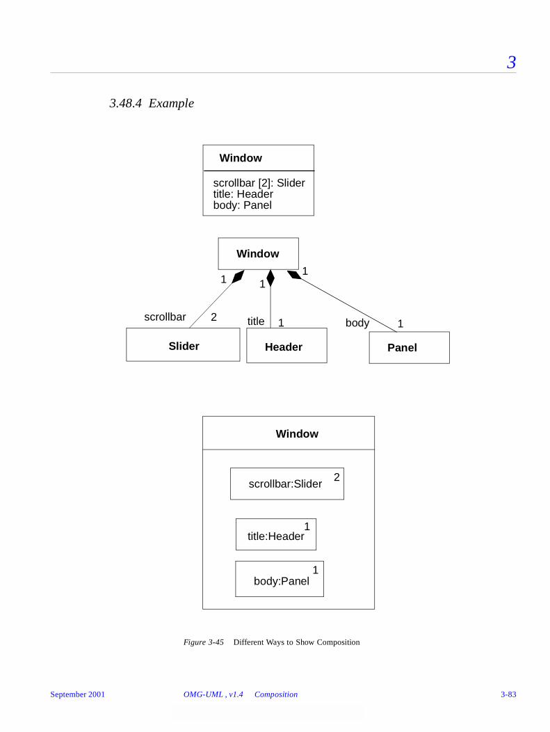
3
3.48.4 Example
Figure 3-45 Different Ways to Show Composition
Window
scrollbar [2]: Slidertitle: Headerbody: Panel
Window
scrollbar title body
scrollbar:Slider
Header Panel
2 1 1
Window
Slider
2
title:Header1
body:Panel1
111
September 2001 OMG-UML , v1.4 Composition 3-83
3
3.48.5 Mapping
A class box with an attribute compartment maps into a Class with Attributes. Although attributes may be semantically equivalent to composition on a deep level, the mapped model distinguishes the two forms.
A solid diamond on an association path maps into the aggregation-composition property on the corresponding Association Role.
A class box with contained class boxes maps into a set of composition associations; that is, one composition association between the Class corresponding to the outer class box and each of the Classes corresponding to the enclosed class boxes. The multiplicity of the composite end of each association is 1. The multiplicity of each constituent end is 1 if not specified explicitly; otherwise, it is the value specified in the corner of the class box or specified on an association path from the outer class box boundary to an inner class box.
3.49 Link
3.49.1 Semantics
A link is a tuple (list) of object references. Most commonly, it is a pair of object references. It is an instance of an association.
3.49.2 Notation
A binary link is shown as a path between two instances. In the case of a link from an instance to itself, it may involve a loop with a single instance. See “Association” on page 3-68 for details of paths.
A rolename may be shown at each end of the link. An association name may be shown near the path. If present, it is underlined to indicate an instance. Links do not have instance names, they take their identity from the instances that they relate. Multiplicity is not shown for links because they are instances. Other association adornments (aggregation, composition, navigation) may be shown on the link ends.
A qualifier may be shown on a link. The value of the qualifier may be shown in its box.
3-84 OMG-Unified Modeling Language, v1.4 September 2001

3
3.49.2.1 Implementation stereotypes
A stereotype may be attached to the link end to indicate various kinds of implementation. The following stereotypes may be used:
3.49.2.2 N-ary link
An n-ary link is shown as a diamond with a path to each participating instance. The other adornments on the association, and the adornments on the association ends, have the same possibilities as the binary link.
3.49.3 Example
Figure 3-46 Links
«association» association (default, unnecessary to specify except for emphasis)
«parameter» method parameter
«local» local variable of a method
«global» global variable
«self» self link (the ability of an instance to send a message to itself)
downhillSkiClub:Club Joe:Person
Jill:Person
Chris:Person
member
member
member
treasurer
officer
president
officer
September 2001 OMG-UML , v1.4 Link 3-85
3
3.49.4 Mapping
Within an object diagram, each link path maps to a Link between the Instances corresponding to the connected class boxes. If a name is placed on the link path, then it is an instance of the given Association (and the rolenames must match or the diagram is ill formed).
3.50 Generalization
3.50.1 Semantics
Generalization is the taxonomic relationship between a more general element (the parent) and a more specific element (the child) that is fully consistent with the first element and that adds additional information. It is used for classes, packages, use cases, and other elements.
3.50.2 Notation
Generalization is shown as a solid-line path from the child (the more specific element, such as a subclass) to the parent (the more general element, such as a superclass), with a large hollow triangle at the end of the path where it meets the more general element.
A generalization path may have a text label called a discriminator that is the name of a partition of the children of the parent. The child is declared to be in the given partition. The absence of a discriminator label indicates the “empty string” discriminator which is a valid value (the “default” discriminator).
Generalization may be applied to associations as well as to classes. To notate generalization between associations, a generalization arrow may be drawn from a child association path to a parent association path. This notation may be confusing because lines connect other lines. An alternative notation is to represent each association as an association class and to draw the generalization arrow between the rectangles for the association classes, as with other classifiers. This approach can be used even if an association does not have any additional attributes, because a degenerate association class is a legal association.
The existence of additional children in the model that are not shown on a particular diagram may be shown using an ellipsis (. . .) in place of a child.
Note – This does not indicate that additional children may be added in the future. It indicates that additional children exist right now, but are not being seen. This is a notational convention that information has been suppressed, not a semantic statement.
3-86 OMG-Unified Modeling Language, v1.4 September 2001
3
Predefined constraints may be used to indicate semantic constraints among the children. A comma-separated list of keywords is placed in braces either near the shared triangle (if several paths share a single triangle) or near a dotted line that crosses all of the generalization lines involved. The following keywords (among others) may be used (the following constraints are predefined):
The discriminator must be unique among the attributes and association roles of the given parent. Multiple occurrences of the same discriminator name are permitted and indicate that the children belong to the same partition.
The use of multiple classification or dynamic classification affects the dynamic execution semantics of the language, but is not usually apparent from a static model.
3.50.3 Presentation Options
A group of generalization paths for a given parent may be shown as a tree with a shared segment (including the triangle) to the child, branching into multiple paths to each child.
If a text label is placed on a generalization triangle shared by several generalization paths to children, the label applies to all of the paths. In other words, all of the children share the given properties.
overlapping An element may have two or more children from the set as ancestors. An instance may be a direct or indirect instance of two or more of the children.
disjoint No element may have two children in the set as ancestors. No instance may be a direct or indirect instance of tow of the children.
complete All children have been specified (whether or not shown). No additional children are expected.
incomplete Some children have been specified, but the list is known to be incomplete. There are additional children that are not yet in the model. This is a statement about the model itself. Note that this is not the same as the ellipsis, which states that additional children exist in the model but are not shown on the current diagram.
September 2001 OMG-UML , v1.4 Generalization 3-87

3
3.50.4 Example
Figure 3-47 Styles of Displaying Generalizations
Shape
SplineEllipsePolygon
Shape
SplineEllipsePolygon
Shared Target Style
Separate Target Style
. . .
. . .
3-88 OMG-Unified Modeling Language, v1.4 September 2001

3
Figure 3-48 Generalization with Discriminators and Constraints, Separate Target Style
Figure 3-49 Generalization with Shared Target Style
3.50.5 Mapping
Each generalization path between two element symbols maps into a Generalization between the corresponding GeneralizableElements. A generalization tree with one arrowhead and many tails maps into a set of Generalizations, one between each
Vehicle
WindPoweredVehicle
MotorPoweredVehicle
LandVehicle
WaterVehicle
venue
venuepowerpower
SailboatTruck
{overlapping} {overlapping}
Tree
Oak Elm
{disjoint, incomplete}
Birch
species
September 2001 OMG-UML , v1.4 Generalization 3-89
3
element corresponding to a symbol on a tail and the single GeneralizableElement corresponding to the symbol on the head. That is, a tree is semantically indistinguishable from a set of distinct arrows, it is purely a notational convenience.
Any property string attached to a generalization arrow applies to the Generalization. A property string attached to the head line segment on a generalization tree represents a (duplicated) property on each of the individual Generalizations.
The presence of an ellipsis (“...”) as a child node of a given parent indicates that the semantic model contains at least one child of the given parent that is not visible on the current diagram. Normally, this indicator will be maintained automatically by an editing tool.
3.51 Dependency
3.51.1 Semantics
A dependency indicates a semantic relationship between two model elements (or two sets of model elements). It relates the model elements themselves and does not require a set of instances for its meaning. It indicates a situation in which a change to the target element may require a change to the source element in the dependency.
3.51.2 Notation
A dependency is shown as a dashed arrow between two model elements. The model element at the tail of the arrow (the client) depends on the model element at the arrowhead (the supplier). The arrow may be labeled with an optional stereotype and an optional individual name.
It is possible to have a set of elements for the client or supplier. In this case, one or more arrows with their tails on the clients are connected to the tails of one or more arrows with their heads on the suppliers. A small dot can be placed on the junction if desired. A note on the dependency should be attached at the junction point.
The following kinds of Dependency are predefined and may be indicated with keywords. Note that some of these correspond to actual metamodel classes and others to stereotypes of metamodel classes. All of these are shown as dashed arrows with keywords in guillemets. The name column shows the name of the metamodel class or the informal name of the class with the given keyword stereotype.
3-90 OMG-Unified Modeling Language, v1.4 September 2001
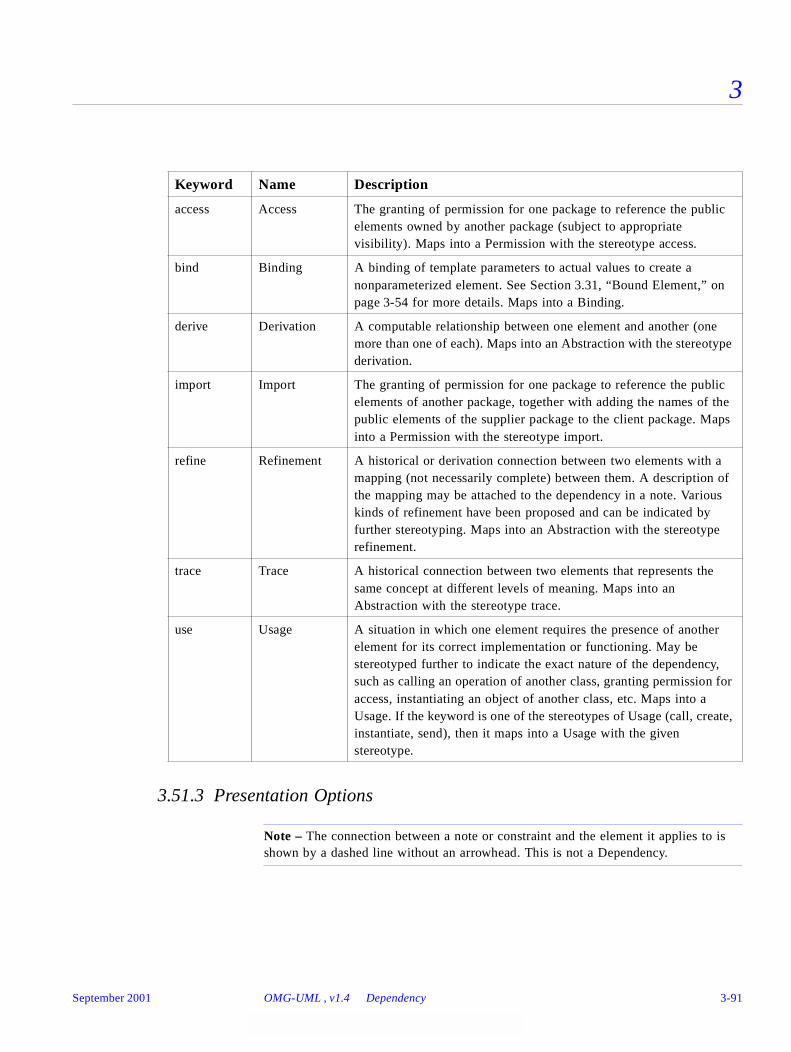
3
3.51.3 Presentation Options
Note – The connection between a note or constraint and the element it applies to is shown by a dashed line without an arrowhead. This is not a Dependency.
Keyword Name Description
access Access The granting of permission for one package to reference the public elements owned by another package (subject to appropriate visibility). Maps into a Permission with the stereotype access.
bind Binding A binding of template parameters to actual values to create a nonparameterized element. See Section 3.31, “Bound Element,” on page 3-54 for more details. Maps into a Binding.
derive Derivation A computable relationship between one element and another (one more than one of each). Maps into an Abstraction with the stereotype derivation.
import Import The granting of permission for one package to reference the public elements of another package, together with adding the names of the public elements of the supplier package to the client package. Maps into a Permission with the stereotype import.
refine Refinement A historical or derivation connection between two elements with a mapping (not necessarily complete) between them. A description of the mapping may be attached to the dependency in a note. Various kinds of refinement have been proposed and can be indicated by further stereotyping. Maps into an Abstraction with the stereotype refinement.
trace Trace A historical connection between two elements that represents the same concept at different levels of meaning. Maps into an Abstraction with the stereotype trace.
use Usage A situation in which one element requires the presence of another element for its correct implementation or functioning. May be stereotyped further to indicate the exact nature of the dependency, such as calling an operation of another class, granting permission for access, instantiating an object of another class, etc. Maps into a Usage. If the keyword is one of the stereotypes of Usage (call, create, instantiate, send), then it maps into a Usage with the given stereotype.
September 2001 OMG-UML , v1.4 Dependency 3-91
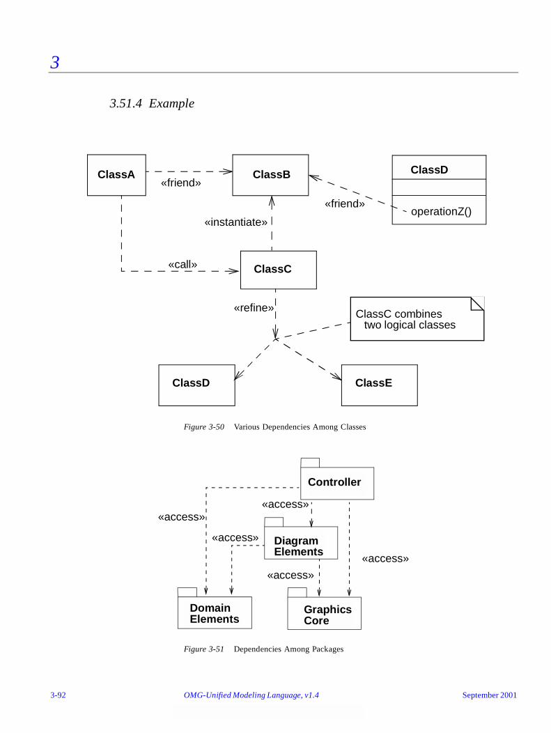
3
3.51.4 Example
Figure 3-50 Various Dependencies Among Classes
Figure 3-51 Dependencies Among Packages
«friend»ClassA ClassB
ClassC
«instantiate»
«call»
ClassD
operationZ()«friend»
ClassD ClassE
«refine» ClassC combinestwo logical classes
Controller
DiagramElements
DomainElements
GraphicsCore
«access»
«access»
«access»
«access»
«access»
3-92 OMG-Unified Modeling Language, v1.4 September 2001
3
3.51.5 Mapping
A dashed arrow maps into the appropriate kind of Dependency (based on keywords) between the Elements corresponding to the symbols attached to the ends of the arrow. The stereotype and the name (if any) attached to the arrow are the stereotype and name of the Dependency.
3.52 Derived Element
3.52.1 Semantics
A derived element is one that can be computed from another one, but that is shown for clarity or that is included for design purposes even though it adds no semantic information.
3.52.2 Notation
A derived element is shown by placing a slash (/) in front of the name of the derived element, such as an attribute or a rolename.
3.52.3 Style Guidelines
The details of computing a derived element can be specified by a dependency with the stereotype «derive». Usually it is convenient in the notation to suppress the dependency arrow and simply place a constraint string near the derived element, although the arrow can be included when it is helpful.
3.53 InstanceOf
3.53.1 Semantics
Shows the connection between an instance and its classifier.
3.53.2 Notation
Shown as a dashed arrow with its tail on the instance and its head on the classifier. The arrow has the keyword «instanceOf».
3.53.3 Mapping
Maps into an instance relationship from the instance to the classifier.
September 2001 OMG-UML , v1.4 Derived Element 3-93
3
Part 6 - Use Case DiagramsA use case diagram shows the relationship among use cases within a system or other semantic entity and their actors.
3.54 Use Case Diagram
3.54.1 Semantics
Use case diagrams show actors and use cases together with their relationships. The use cases represent functionality of a system or a classifier, like a subsystem or a class, as manifested to external interactors with the system or the classifier.
3.54.2 Notation
A use case diagram is a graph of actors, a set of use cases, possibly some interfaces, and the relationships between these elements. The relationships are associations between the actors and the use cases, generalizations between the actors, and generalizations, extends, and includes among the use cases. The use cases may optionally be enclosed by a rectangle that represents the boundary of the containing system or classifier.
3-94 OMG-Unified Modeling Language, v1.4 September 2001
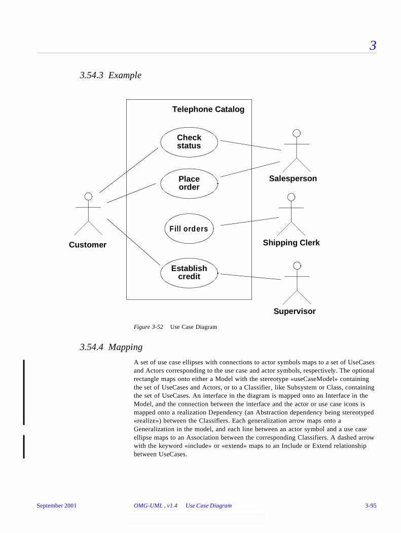
3
3.54.3 Example
Figure 3-52 Use Case Diagram
3.54.4 Mapping
A set of use case ellipses with connections to actor symbols maps to a set of UseCases and Actors corresponding to the use case and actor symbols, respectively. The optional rectangle maps onto either a Model with the stereotype «useCaseModel» containing the set of UseCases and Actors, or to a Classifier, like Subsystem or Class, containing the set of UseCases. An interface in the diagram is mapped onto an Interface in the Model, and the connection between the interface and the actor or use case icons is mapped onto a realization Dependency (an Abstraction dependency being stereotyped «realize») between the Classifiers. Each generalization arrow maps onto a Generalization in the model, and each line between an actor symbol and a use case ellipse maps to an Association between the corresponding Classifiers. A dashed arrow with the keyword «include» or «extend» maps to an Include or Extend relationship between UseCases.
Customer
Supervisor
SalespersonPlace
Establishcredit
Check
Telephone Catalog
Fill orders
Shipping Clerk
status
order
September 2001 OMG-UML , v1.4 Use Case Diagram 3-95
3
3.55 Use Case
3.55.1 Semantics
A use case is a kind of classifier representing a coherent unit of functionality provided by a system, a subsystem, or a class as manifested by sequences of messages exchanged among the system (subsystem, class) and one or more outside interactors (called actors) together with actions performed by the system (subsystem, class).
An extension point is a reference to one location within a use case at which action sequences from other use cases may be inserted. Each extension point has a unique name within a use case, and a description of the location within the behavior of the use case.
3.55.2 Notation
A use case is shown as an ellipse containing the name of the use case. An optional stereotype keyword may be placed above the name and a list of properties included below the name. As a classifier, a use case may also have compartments displaying attributes and operations.
Extension points may be listed in a compartment of the use case with the heading extension points. The description of the locations of the extension point is given in a suitable form, usually as ordinary text, but can also be given in other forms, like the name of a state in a state machine, or a precondition or a postcondition.
The behavior of a use case can be described in several different ways, depending on what is convenient: often plain text is used, but state machines, and operations and methods are examples of other ways of describing the behavior of the use case. Sequence diagrams can be used for describing the interaction between use cases and their actors.
3.55.3 Presentation Options
The name of the use case may be placed below the ellipse. The name of an abstract use case may be shown in italics.
The ellipse may contain or suppress compartments presenting the attributes, the operations, and the extension points of the use case.
3.55.4 Style Guidelines
Use case names should follow capitalization and punctuation guidelines used for Classifiers in the model.
3-96 OMG-Unified Modeling Language, v1.4 September 2001
3
3.55.5 Mapping
A use case symbol maps to a UseCase with the given name. An extension point maps into an ExtensionPoint within the UseCase.
3.56 Actor
3.56.1 Semantics
An actor defines a coherent set of roles that users of an entity can play when interacting with the entity. An actor may be considered to play a separate role with regard to each use case with which it communicates.
3.56.2 Notation
The standard stereotype icon for an actor is a “stick man” figure with the name of the actor below the figure.
3.56.3 Presentation Options
An actor may also be shown as a class rectangle with the keyword «actor», with the usual notation for all compartments. Other icons which convey the kind of actor may also be used to denote an actor.
3.56.4 Style Guidelines
Actor names should follow capitalization and punctuation guidelines used for types and classes in the model.
3.56.5 Mapping
An actor symbol maps to an Actor with the given name. The names of abstract actors may be shown in italics
3.57 Use Case Relationships
3.57.1 Semantics
There are several standard relationships among use cases or between actors and use cases.
• Association – The participation of an actor in a use case; that is, instances of the actor and instances of the use case communicate with each other. This is the only relationship between actors and use cases.
September 2001 OMG-UML , v1.4 Actor 3-97
3
• Extend – An extend relationship from use case A to use case B indicates that an instance of use case B may be augmented (subject to specific conditions specified in the extension) by the behavior specified by A. The behavior is inserted at the location defined by the extension point in B, which is referenced by the extend relationship.
• Generalization – A generalization from use case C to use case D indicates that C is a specialization of D.
• Include – An include relationship from use case E to use case F indicates that an instance of the use case E will also contain the behavior as specified by F. The behavior is included at the location which defined in E.
3.57.2 Notation
An association between an actor and a use case is shown as a solid line between the actor and the use case. It may have end adornments such as multiplicity.
An extend relationship between use cases is shown by a dashed arrow with an open arrow-head from the use case providing the extension to the base use case. The arrow is labeled with the keyword «extend». The condition of the relationship is optionally presented close to the key-word.
An include relationship between use cases is shown by a dashed arrow with an open arrow-head from the base use case to the included use case. The arrow is labeled with the keyword «include».
A generalization between use cases is shown by a generalization arrow; that is, a solid line with a closed, hollow arrow head pointing at the parent use case.
The relationship between a use case and its external interaction sequences is usually defined by an invisible hyperlink to sequence diagrams. The relationship between a use case and its realization may be shown as dashed arrow with the keyword «representedClassifier» to collaborations, but may also be defined as invisible hyperlinks.
3-98 OMG-Unified Modeling Language, v1.4 September 2001

3
3.57.3 Example
Figure 3-53 Use Case Relationships
3.57.4 Mapping
A path between use case and/or actor symbols maps into the corresponding relationship between the corresponding Elements, as described above.
3.58 Actor Relationships
3.58.1 Semantics
There is one standard relationship among actors and one between actors and use cases.
• Association – The participation of an actor in a use case; that is, instances of the actor and instances of the use case communicate with each other. This is the only relationship between actors and use cases.
• Generalization – A generalization from an actor A to an actor B indicates that an instance of A can communicate with the same kinds of use-case instances as an instance of B.
3.58.2 Notation
An association between an actor and a use case is shown as a solid line between the actor and the use case.
additional requests :
OrderProduct
SupplyArrange
«include»«include»«include»
RequestCatalog
«extend»Extension points
PaymentCustomer Data
after creation of the order
Salesperson
Place Order
1 * the salesperson asks forthe catalog
September 2001 OMG-UML , v1.4 Actor Relationships 3-99
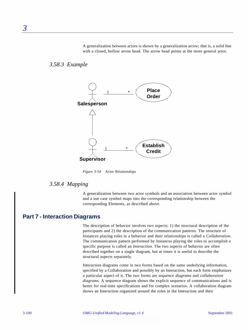
3
A generalization between actors is shown by a generalization arrow; that is, a solid line with a closed, hollow arrow head. The arrow head points at the more general actor.
3.58.3 Example
Figure 3-54 Actor Relationships
3.58.4 Mapping
A generalization between two actor symbols and an association between actor symbol and a use case symbol maps into the corresponding relationship between the corresponding Elements, as described above.
Part 7 - Interaction DiagramsThe description of behavior involves two aspects: 1) the structural description of the participants and 2) the description of the communication patterns. The structure of Instances playing roles in a behavior and their relationships is called a Collaboration. The communication pattern performed by Instances playing the roles to accomplish a specific purpose is called an Interaction. The two aspects of behavior are often described together on a single diagram, but at times it is useful to describe the structural aspects separately.
Interaction diagrams come in two forms based on the same underlying information, specified by a Collaboration and possibly by an Interaction, but each form emphasizes a particular aspect of it. The two forms are sequence diagrams and collaboration diagrams. A sequence diagram shows the explicit sequence of communications and is better for real-time specifications and for complex scenarios. A collaboration diagram shows an Interaction organized around the roles in the Interaction and their
EstablishCredit
PlaceOrder
Salesperson
Supervisor
1 *
1 *
3-100 OMG-Unified Modeling Language, v1.4 September 2001
3
relationships. It does not show time as a separate dimension, so the sequence of communications and the concurrent threads must be determined using sequence numbers.
3.59 Collaboration
3.59.1 Semantics
Behavior is implemented by ensembles of Instances that exchange Stimuli within an overall interaction to accomplish a task. To understand the mechanisms used in a design, it is important to see only those Instances and their cooperation involved in accomplishing a purpose or a related set of purposes, projected from the larger system of which they are part of. Such a static construct is called a Collaboration.
A Collaboration includes an ensemble of ClassifierRoles and AssociationRoles that define the participants needed for a given set of purposes. Instances conforming to the ClassifierRoles play the roles defined by the ClassifierRoles, while Links between the Instances conform to AssociationRoles of the Collaboration. ClassifierRoles and AssociationRoles define a usage of Instances and Links, and the Classifiers and Associations declare all required properties of these Instances and Links.
An Interaction is defined in the context of a Collaboration. It specifies the communication patterns between the roles in the Collaboration. More precisely, it contains a set of partially ordered Messages, each specifying one communication; for example, what Signal to be sent or what Operation to be invoked, as well as the roles to be played by the sender and the receiver, respectively.
A CollaborationInstanceSet references an ensemble of Instances that jointly perform the task specified by the CollaborationInstanceSet’s Collaboration. These Instances play the roles defined by the ClassifierRoles of the Collaboration; that is, the Instances have all the properties declared by the ClassifierRoles (the Instances are said to conform to the ClassifierRoles). The Stimuli sent between the Instances when performing the task are participating in the InteractionInstanceSet of the CollaborationInstanceSet. These Stimuli conform to the Messages in one of the Interactions of the Collaboration. Since an Instance can participate in several CollaborationInstanceSets at the same time, all its communications are not necessarily referenced by only one InteractionInstanceSet. They can be interleaved.
A Collaboration may be attached to an Operation or a Classifier, like a UseCase, to describe the context in which their behavior occurs; that is, what roles Instances play to perform the behavior specified by the Operation or the UseCase. A Collaboration is used for describing the realization of an Operation or a Classifier. A Collaboration which describes a Classifier, like a UseCase, references Classifiers and Associations in general, while a Collaboration describing an Operation includes the arguments and local variables of the Operation, as well as ordinary Associations attached to the Classifier owning the Operation. The Interactions defined within the Collaboration specify the communication pattern between the Instances when they perform the behavior specified in the Operation or the UseCase. These patterns are presented in
September 2001 OMG-UML , v1.4 Collaboration 3-101

3
sequence diagrams or collaboration diagrams. A Collaboration may also be attached to a Class to define the static structure of the Class; that is, how attributes, parameters, etc. cooperate with each other.
A parameterized Collaboration represents a design construct that can be used repeatedly in different designs. The participants in the Collaboration, including the Classifiers and Relationships, can be parameters of the generic Collaboration. The parameters are bound to particular ModelElements in each instantiation of the generic Collaboration. Such a parameterized Collaboration can capture the structure of a design pattern (note that a design pattern involves more than structural aspects). Whereas most Collaborations can be anonymous because they are attached to a named ModelElement, Collaboration patterns are free standing design constructs that must have names.
A Collaboration may be expressed at different levels of granularity. A coarse-grained Collaboration may be refined to produce another Collaboration that has a finer granularity.
3.60 Sequence Diagram
3.60.1 Semantics
A sequence diagram presents an Interaction, which is a set of Messages between ClassifierRoles within a Collaboration, or an InteractionInstanceSet, which is a set of Stimuli between Instances within a CollaborationInstanceSet to effect a desired operation or result.
3.60.2 Notation
A sequence diagram has two dimensions: 1) the vertical dimension represents time and 2) the horizontal dimension represents different instances. Normally time proceeds down the page. (The dimensions may be reversed, if desired.) Usually only time sequences are important, but in real-time applications the time axis could be an actual metric. There is no significance to the horizontal ordering of the instances.
The different kinds of arrows used in sequence diagrams are described in Section 3.63, “Message and Stimulus,” on page 3-111, below. These are the same kinds as in collaboration diagrams; see Section 3.65, “Collaboration Diagram,” on page 3-115.
Note that much of this notation is drawn directly from the Object Message Sequence Chart notation of Buschmann, Meunier, Rohnert, Sommerlad, and Stal, which is itself derived with modifications from the Message Sequence Chart notation.
3.60.3 Presentation Options
The horizontal ordering of the lifelines is arbitrary. Often call arrows are arranged to proceed in one direction across the page; however, this is not always possible and the ordering does not convey information.
3-102 OMG-Unified Modeling Language, v1.4 September 2001

3
The axes can be interchanged, so that time proceeds horizontally to the right and different objects are shown as horizontal lines.
Various labels (such as timing constraints, descriptions of actions during an activation, and so on) can be shown either in the margin or near the transitions or activations that they label.
Timing constraints may be expressed using time expressions on message or stimuli names. The functions sendTime (the time at which a stimulus is sent by an instance) and receiveTime (the time at which a stimulus is received by an instance) may be applied to stimuli names to yield a time. The set of time functions is open-ended, so that users can invent new ones as needed for special situations or implementation distinctions (such as elapsedTime, executionStartTime, queuedTime, handledTime, etc.)
Construction marks of the kind found in blueprints can be used to indicate a time interval to which a constraint may be attached (see bottom right of Figure 3-55 on page 3-104). This notation is visually appealing but it is ambiguous if the arrow is horizontal, because the send time and the receive time cannot be distinguished. In many cases the transmission time is negligible, so the ambiguity is harmless, but a tool must nevertheless map such a notation unambiguously to an expression on message or stimuli names (as shown in the examples in the left of the diagram) before the information is placed in the semantic model. (A tool may adopt defaults for this mapping.) Similarly, a tool might permit the time function to be elided and use the stimulus name to denote the time of stimulus sending or receipt within a timing expression (such as “b.receiveTime - a.sendTime < 1 sec.” in Figure 3-55), but again this is only a surface notation that must be mapped to a proper time expression in the semantic model).
September 2001 OMG-UML , v1.4 Sequence Diagram 3-103
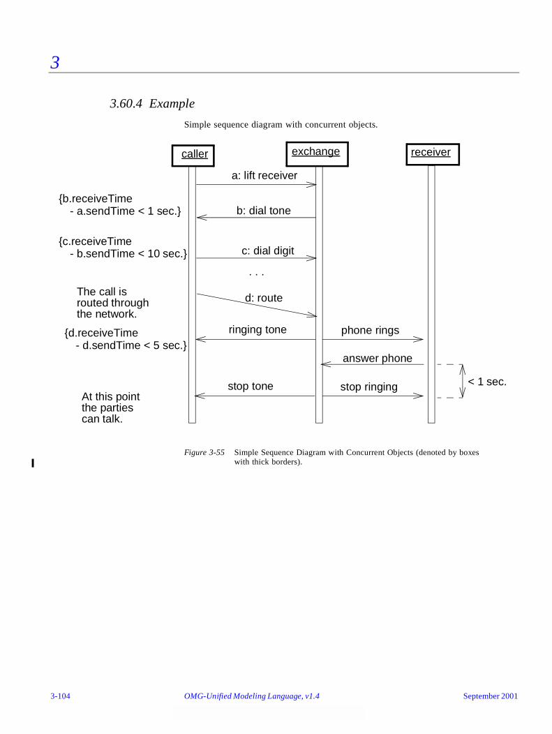
3
3.60.4 Example
Simple sequence diagram with concurrent objects.
Figure 3-55 Simple Sequence Diagram with Concurrent Objects (denoted by boxes with thick borders).
caller exchange
a: lift receiver
b: dial tone
c: dial digit
{b.receiveTime
{c.receiveTime
. . .
d: route
{d.receiveTime
receiver
phone ringsringing tone
answer phone
stop ringingstop tone
The call isrouted throughthe network.
At this pointthe partiescan talk.
- a.sendTime < 1 sec.}
- b.sendTime < 10 sec.}
- d.sendTime < 5 sec.}
< 1 sec.
3-104 OMG-Unified Modeling Language, v1.4 September 2001
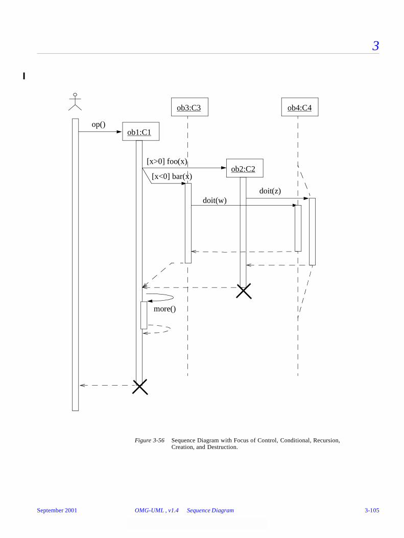
3
Figure 3-56 Sequence Diagram with Focus of Control, Conditional, Recursion, Creation, and Destruction.
[x>0] foo(x)
[x<0] bar(x)
doit(z)doit(w)
more()
ob1:C1
ob2:C2
ob3:C3 ob4:C4
op()
September 2001 OMG-UML , v1.4 Sequence Diagram 3-105
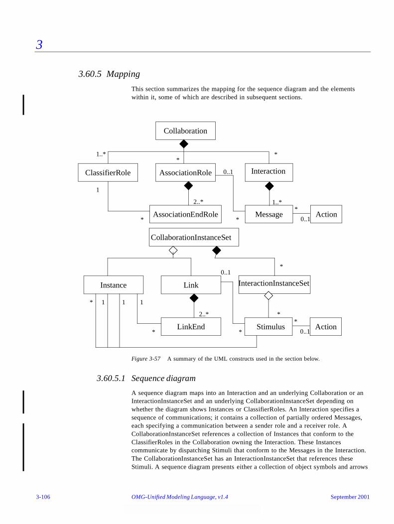
3
3.60.5 Mapping
This section summarizes the mapping for the sequence diagram and the elements within it, some of which are described in subsequent sections.
Figure 3-57 A summary of the UML constructs used in the section below.
3.60.5.1 Sequence diagram
A sequence diagram maps into an Interaction and an underlying Collaboration or an InteractionInstanceSet and an underlying CollaborationInstanceSet depending on whether the diagram shows Instances or ClassifierRoles. An Interaction specifies a sequence of communications; it contains a collection of partially ordered Messages, each specifying a communication between a sender role and a receiver role. A CollaborationInstanceSet references a collection of Instances that conform to the ClassifierRoles in the Collaboration owning the Interaction. These Instances communicate by dispatching Stimuli that conform to the Messages in the Interaction. The CollaborationInstanceSet has an InteractionInstanceSet that references these Stimuli. A sequence diagram presents either a collection of object symbols and arrows
Collaboration
ClassifierRole AssociationRole Interaction
AssociationEndRole Message
1..**
*
1
*
2..*
0..1
*
1..*
Instance Link
StimulusLinkEnd
2..*
1
*
* 1 1
*
*
0..1
Action0..1
*
Action0..1
*
CollaborationInstanceSet
InteractionInstanceSet
*
3-106 OMG-Unified Modeling Language, v1.4 September 2001
3
mapping to Instances and Stimuli, or a collection of classifier-role symbols and arrows mapping to ClassifierRoles and Messages. The Instances and Stimuli conform to the ClassifierRoles and Messages.
The sequence diagram presents either a Collaboration or a CollaborationInstanceSet. In the former case, the classifier box with its lifeline maps onto a ClassifierRole in the Collaboration, and the arrows map onto the Messages in one of the Collaboration’s Interactions. The name strings in the boxes map onto the names of the ClassifierRoles, while the classifier names map onto the ClassifierRole’s base Classifiers. The AssociationRoles among the ClassifierRoles are not shown on the sequence diagram. They must be obtained in the model from a complementary collaboration diagram or other means.
If the sequence diagram presents a CollaborationInstanceSet, each object box with its lifeline maps into an Instance, which conforms to a ClassifierRole in the CollaborationInstanceSet’s Collaboration. The name field maps into the name of the Instance, the role name into the ClassifierRole’s name, and the class field maps into the names of the Classifiers being the base Classifiers of the ClassifierRole. An arrow maps into a Stimulus connected to two Instances: the sender and the receiver. The Link used for the communication of the Stimulus plays the role specified by the AssociationRole connected to the Message. Unless the correct Link can be determined from a complementary collaboration diagram or other means, the Stimulus is either not attached to a Link (not a complete model), or it is attached to an arbitrary Link or to a dummy Link between the Instances conforming to the AssociationRole implied by the two ClassifierRoles due to the lack of complete information.
The name of the Operation to be invoked or Signal to be sent is mapped onto the name of the Operation or Signal associated by the Action connected to the Message. Different alternatives exist for showing the arguments of the Stimulus. If references to the actual Instances being passed as arguments are shown, these are mapped onto the arguments of the Stimulus. If the argument expressions are shown instead, these are mapped onto the Arguments of the Action connected to the dispatching Action. Finally, if the types of the arguments are shown together with the name of the Operation or the Signal, these are mapped onto the parameter types of the Operation or the Attribute types of the Signal, respectively. A timing label placed on the level of an arrow endpoint maps into the name of the corresponding Message or Stimulus. A constraint placed on the diagram maps into a Constraint on the entire Interaction.
An arrow with the arrowhead pointing to an object symbol or role symbol within the frame of the diagram maps into a Stimulus (Message) dispatched by a CreateAction. The interpretation is that an Instance is created by dispatching the Stimulus. If the target of the arrow is a classifier-role symbol, the Instance will conform to the ClassifierRole. (Note, that the diagram does not necessarily show from which Classifier the Instance originates; only that the newly created Instance conforms to the ClassifierRole.) After the creation of the Instance, it may immediately start interacting with other Instances. This implies that the creation method (constructor, initializer) of the Instance dispatches these Stimuli. If an object termination symbol (“X”) is the target of an arrow, the arrow maps into a Stimulus, which will cause the receiving Instance to be removed. If the object termination symbol appears in the diagram without an incoming arrow, it maps into a TerminateAction.
September 2001 OMG-UML , v1.4 Sequence Diagram 3-107
3
The order of the arrows in the diagram maps onto pairs of associations between the Stimuli (Messages). A predecessor relationship is established between Stimuli (Messages) corresponding to successive arrows in the vertical sequence. In case of concurrent arrows preceding an arrow, the corresponding Stimulus (Message) has a collection of predecessors. Moreover, each Stimulus (Message) has an activator association to the Stimulus (Message) corresponding to the incoming arrow of the activation.
Procedural sequence diagram
On a procedural sequence diagram (one with focus of control and calls), subsequent arrows on the same lifeline map into Stimuli (Messages) obeying the predecessor association. An arrow to the head of a focus of control region establishes a nested activation. The arrow maps into a Stimulus (Message) with the dispatching Action being a CallAction. The Stimulus holds the sender and receiver Instance, as well as the argument Instances, to be supplied in the invocation and references the target Operation to be invoked. The expressions that evaluate to the arguments of the Operation are the argument Expressions on the CallAction connected to the Stimulus. In the case where the arrow maps onto a Message the sender and the receiver are specified by the sender and receiver ClassifierRoles of the Message. The sender and receiver Instances of a Stimulus conform to these ClassifierRoles. Any condition or iteration expression attached to the arrow becomes recurrence values of the dispatching Action. All arrows departing the nested activation map into Stimuli (Messages) with an activation Association to the Stimulus (Message) corresponding to the arrow at the head of the activation. A return arrow departing the end of the activation maps into a Stimulus (Message) with:
• an activation Association to the Stimulus (Message) corresponding to the arrow at the head of the activation, and
• a predecessor association to the previous Stimulus (Message) within the same activation; that is, the last Stimulus (Message) being sent in the activation.
A return must be the final Stimulus (Message) within a predecessor chain. It is not the predecessor of any Stimulus (Message).
3.61 Object Lifeline
3.61.1 Semantics
In a sequence diagram an object lifeline denotes an Instance playing a specific role. Arrows between the lifelines denote communication between the Instances playing those roles. Within a sequence diagram the existence and duration of the Instance in a role is shown, but the relationships among the Instances are not shown. The role is specified by a ClassifierRole; it describes the properties of an Instance playing the role and describes the relationships an Instance in that role has to other Instances.
3-108 OMG-Unified Modeling Language, v1.4 September 2001

3
3.61.2 Notation
An Instance is shown as a vertical dashed line called the “lifeline.” The lifeline represents the existence of the Instance at a particular time. If the Instance is created or destroyed during the period of time shown on the diagram, then its lifeline starts or stops at the appropriate point; otherwise, it goes from the top to the bottom of the diagram. An object symbol is drawn at the head of the lifeline. If the Instance is created during the diagram, then the arrow, which maps onto the Stimulus that creates the Instance, is drawn with its arrowhead on the object symbol. If the Instance is destroyed during the diagram, then its destruction is marked by a large “X,” either at the arrow mapping to the Stimulus that causes the destruction or (in the case of self-destruction) at the final return arrow from the destroyed Instance. An Instance that exists when the transaction starts is shown at the top of the diagram (above the first arrow), while an Instance that exists when the transaction finishes has its lifeline continue beyond the final arrow.
The lifeline may split into two or more concurrent lifelines to show conditionality. Each separate track corresponds to a conditional branch in the communication. The lifelines may merge together at some subsequent point.
3.61.3 Presentation Options
In some cases, it is necessary to link sequence diagrams to each other; for example, it might not be possible to put all lifelines in one diagram, or a sub-sequence is included in several diagrams; hence, it is convenient to put the common sub-sequence in a separate diagram, which is referenced from the other diagrams. In these cases, the cut between the diagrams can be expressed in one of the diagrams with a dangling arrow leaving a lifeline but not arriving at another lifeline, and in the other diagram it is expressed with a dangling arrow arriving at a lifeline from nowhere. In both cases, it is recommended to attach a note stating which diagram the sequence originates from or continues in. This is purely notational. The different diagrams show different parts of the underlying Interaction.
3.61.4 Example
See also Figure 3-56 on page 3-105.
September 2001 OMG-UML , v1.4 Object Lifeline 3-109
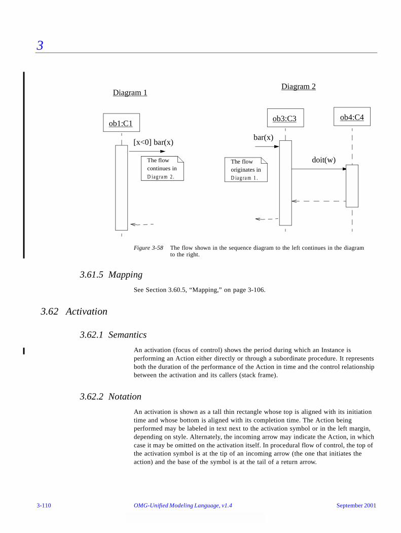
3
Figure 3-58 The flow shown in the sequence diagram to the left continues in the diagram to the right.
3.61.5 Mapping
See Section 3.60.5, “Mapping,” on page 3-106.
3.62 Activation
3.62.1 Semantics
An activation (focus of control) shows the period during which an Instance is performing an Action either directly or through a subordinate procedure. It represents both the duration of the performance of the Action in time and the control relationship between the activation and its callers (stack frame).
3.62.2 Notation
An activation is shown as a tall thin rectangle whose top is aligned with its initiation time and whose bottom is aligned with its completion time. The Action being performed may be labeled in text next to the activation symbol or in the left margin, depending on style. Alternately, the incoming arrow may indicate the Action, in which case it may be omitted on the activation itself. In procedural flow of control, the top of the activation symbol is at the tip of an incoming arrow (the one that initiates the action) and the base of the symbol is at the tail of a return arrow.
bar(x)
doit(w)
ob3:C3 ob4:C4
[x<0] bar(x)
ob1:C1
Diagram 1Diagram 2
The flowcontinues inD iag ra m 2 .
The floworiginates inD ia g ra m 1 .
3-110 OMG-Unified Modeling Language, v1.4 September 2001

3
In the case of concurrent Instances each with their own threads of control, an activation shows the duration when each Instance is performing an Operation or transition in a state machine. Operations by other Instances are not relevant. If the distinction between direct computation and indirect computation (by a nested procedure) is unimportant, the entire lifeline may be shown as an activation.
In the case of procedural code, an activation shows the duration during which a procedure is active in the Instance or a subordinate procedure is active, possibly in some other Instances. In other words, all of the active nested procedure activations may be seen at a given time. In the case of a recursive call to an Instance with an existing activation, the second activation symbol is drawn slightly to the right of the first one, so that they appear to “stack up” visually. (Recursive calls may be nested to an arbitrary depth.)
3.62.3 Example
See Figure 3-55 on page 3-104 and Figure 3-56 on page 3-105.
3.62.4 Mapping
See Section 3.60.5, “Mapping,” on page 3-106.
3.63 Message and Stimulus
3.63.1 Semantics
A Stimulus is a communication between two Instances that conveys information with the expectation that action will ensue. A Stimulus will cause an Operation to be invoked, raise a Signal, or cause an Instance to be created or destroyed.
A Message is a specification of Stimulus; that is, it specifies the roles that the sender and the receiver Instances must conform to, as well as the Action which will, when executed, dispatch a Stimulus that conforms to the Message.
3.63.2 Notation
In a sequence diagram a Stimulus as well as a Message is shown as a horizontal solid arrow from the lifeline of one Instance or ClassifierRole to the lifeline of another Instance or ClassifierRole. In case of a Stimulus from an Instance to itself, the arrow may start and finish on the same lifeline. The arrow is labeled with the name of the Operation to be invoked or the name of the Signal. Its argument values or argument expressions may be presented, as well.
The arrow may also be labeled with a sequence number to show the sequence of the Stimulus (Message) in the overall interaction. However, sequence numbers are often omitted in sequence diagrams, as the physical location of the arrow shows the relative
September 2001 OMG-UML , v1.4 Message and Stimulus 3-111

3
sequences, but they are necessary in collaboration diagrams. Sequence numbers are useful on both kinds of diagrams for identifying concurrent threads of control. An arrow may also be labeled with a condition and/or iteration expression.
3.63.3 Presentation options
The following arrowhead variations may be used to show different kinds of communications.
filled solid arrowhead
Procedure call or other nested flow of control. The entire nested sequence is completed before the outer level sequence resumes. The arrowhead may be used to denote ordinary procedure calls, but it may also be used to denote concurrently active instances when one of them sends a Signal and waits for a nested sequence of behavior to complete before it continues.
stick arrowhead
Asynchronous communication; that is, no nesting of control. The sender dispatches the Stimulus and immediately continues with the next step in the execution.1
dashed arrow with stick arrowhead
Return from procedure call.
Variation:
In a procedural flow of control, the return arrow may be omitted (it is implicit at the end of an activation). It is assumed that every call has a paired return after any subordinate stimuli. The return value can be shown on the initial arrow. For nonprocedural flow of control (including parallel processing and asynchronous messages) returns should be shown explicitly.
Variation:
Normally message arrows are drawn horizontally. This indicates the duration required to send the stimulus is “atomic;” that is, it is brief compared to the granularity of the interaction and that nothing else can “happen” during the transmission of the stimulus. This is the correct assumption within many computers.
1.UML 1.3 and previous versions included a half-stick arrowhead notation in addition to the stick arrowhead notation. This notation has been removed because the semantic distinction between the two was subtle and confusing.
3-112 OMG-Unified Modeling Language, v1.4 September 2001
3
If the stimulus requires some time to arrive, during which something else can occur (such as a stimulus in the opposite direction), then the arrow may be slanted downward so that the arrowhead is below the arrow tail.
Variation: Branching
A branch is shown by multiple arrows leaving a single point, each possibly labeled by a condition. Depending on whether the conditions are mutually exclusive, the construct may represent conditionality or concurrency.
Variation: Iteration
A connected set of arrows may be enclosed and marked as an iteration. For a generic sequence diagram, the iteration indicates that the dispatch of a set of stimuli can occur multiple times. For a procedure, the continuation condition for the iteration may be specified at the bottom of the iteration. If there is concurrency, then some arrows in the diagram may be part of the iteration and others may be single execution. It is desirable to arrange a diagram so that the arrows in the iteration can be enclosed together easily.
Variation:
A lifeline may subsume an entire set of objects on a diagram representing a high-level view.
Variation:
A distinction may be made between a period during which an Instance has a live activation and a period in which the activation is actually computing. The former (during which it has control information on a stack but during which control resides in something that it called) is shown with the ordinary double line. The latter (during which it is the top item on the stack) may be distinguished by shading the region.
3.63.4 Example
See Figure 3-56 on page 3-105.
3.63.5 Mapping
See Section 3.60.5, “Mapping,” on page 3-106.
September 2001 OMG-UML , v1.4 Message and Stimulus 3-113
3
3.64 Transition Times
3.64.1 Semantics
A Message may specify several different times; for example, a sending time and a receiving time. These are formal names that may be used within Constraint expressions. The set of different kinds of times is open-ended so that users can invent new ones as needed for special situations, such as elapsedTime and startExecutionTime. These expressions may be used in Constraints to designate specific time constraints valid for the Message.
3.64.2 Notation
A transition instance (such as a Stimulus or Message in a sequence diagram, a collaboration diagram, or a Transition in a state machine) may be given a name. A timing constraint is formed as an expression based on the name of the transition. For example, if the name of a Stimulus is stim, its send-time is expressed by stim.sendTime (), and its receive-time by stim.receiveTime (). The timing constraint may be shown in the left margin aligned with the arrow (on a sequence diagram) or near the tail of the arrow (on a collaboration diagram). Constraints may be specified by placing Boolean expressions, possibly including time expressions, in braces on the sequence diagram.
3.64.3 Presentation Options
When it is clear from the context, the name of a Message or the name of a Stimulus may itself be used to denote the time at which the transition started. In cases where the performance of the transition is not instantaneous, the time at which the transition is ended may be indicated by the same name with a prime sign appended to the name.
3.64.4 Example
See Figure 3-55 on page 3-104.
3.64.5 Mapping
See Section 3.60.5, “Mapping,” on page 3-106.
3-114 OMG-Unified Modeling Language, v1.4 September 2001
3
Part 8 - Collaboration Diagrams
3.65 Collaboration Diagram
3.65.1 Semantics
A collaboration diagram presents either a Collaboration, which contains a set of roles to be played by Instances, as well as their required relationships given in a particular context, or it presents a CollaborationInstanceSet with a collection of Instances and their relationships. The diagram may also present an Interaction (InteractionInstanceSet), which defines a set of Messages (Stimuli) specifying the interaction between the Instances playing the roles within a Collaboration to achieve the desired result.
A Collaboration is used for describing the realization of an Operation or a Classifier. A Collaboration that describes a Classifier, like a UseCase, references Classifiers and Associations in general, while a Collaboration describing an Operation includes the arguments and local variables of the Operation, as well as ordinary Associations attached to the Classifier owning the Operation.
3.65.2 Notation
A collaboration diagram shows a graph of either Instances linked to each other, or ClassifierRoles and AssociationRoles; it may also include the communication stated by an Interaction or InteractionInstanceSet.
Because collaboration diagrams often are used to help design procedures, they typically show navigability using arrowheads on the lines representing Links or AssociationRoles. (An arrowhead on a line between boxes indicates a Link or AssociationRole with one-way navigability. An arrow next to a line indicates Stimuli or Message flowing in the given direction. Obviously such an arrow cannot point backwards over a one-way line.)
The order of the interaction is described with a sequence of numbers, usually starting with number 1. For a procedural flow of control, the subsequent communication numbers are nested in accordance with call nesting. For a nonprocedural sequence of interactions among concurrent instances, all the sequence numbers are at the same level (that is, they are not nested).
A collaboration diagram without any interaction shows the context in which interactions can occur. It might be used to show the context for a single Operation or even for all of the Operations of a Class or group of Classes.
A collection of standard constraints may be used to show whether an Instance or a Link is created or destroyed during the execution:
• Instances and Links created during the execution may be designated as {new}.
• Instances and Links destroyed during the execution may be designated as {destroyed}.
September 2001 OMG-UML , v1.4 Collaboration Diagram 3-115
3
• Instances and Links created during the execution and then destroyed may be designated as {transient}.
These changes in life state are derivable from the detailed interaction among the Instances, they are provided as notational conveniences.
3.65.2.1 Collaboration Instance
A collaboration diagram given at instance level shows a CollaborationInstanceSet; that is, a collection of object boxes and lines mapping to Instances and Links, respectively. These instances conform to the ClassifierRoles and AssociationRoles of the CollaborationInstanceSet’s Collaboration. The diagram may also include arrows attached to the lines that correspond to Stimuli communicated over the Links. The diagram shows the Instances relevant to the realization of an Operation or Classifier, including Instances indirectly affected or accessed during the performance. The diagram also shows the Links among the Instances, including transient ones representing procedure arguments, local variables, and self links. Individual attribute values are usually not shown explicitly. If Stimuli must be sent to attribute values, the Attributes should be modeled using Associations instead.
3.65.2.2 Collaboration
A collaboration diagram given at specification level shows a Collaboration; that is, the roles defined within a Collaboration. Together, these roles form a realization of the attached Operation or Classifier of the Collaboration. The diagram contains a collection of class boxes and lines corresponding to ClassifierRoles and AssociationRoles in the Collaboration. In this case the arrows attached to the lines map onto Messages.
3-116 OMG-Unified Modeling Language, v1.4 September 2001

3
3.65.3 Example
Figure 3-59 Collaboration Diagram at instance level, presenting Objects, Links, and Stimuli referenced by a CollaborationInstanceSet and its InteractionInstanceSet.
Figure 3-60 Collaboration Diagram at specification level, presenting the ClassifierRolesand the AssociationRoles that belong to the Collaboration.
:Controller
wire: Wire
1: displayPositions(window)
left: Bead
wire
redisplay():Window
i-1 i
right: Bead
1.1.1b: r1:=position()1.1.1a: r0 := position()
1.1.2: create(r0,r1)
window
«parameter»window
1.1*[i:=1..n]: drawSegment(i) :Line {new}«local» line
1.1.3: display(window)
1.1.3.1: add(self)
contents {new}
«self»
/ Teacher : Person
: Facultygiven course *
/ Student : Person
student *
: Course
tutor 1
taken course *
participant *lecturer 1faculty member *
faculty 1
September 2001 OMG-UML , v1.4 Collaboration Diagram 3-117

3
Figure 3-61 Collaboration Diagram presenting a CollaborationInstanceSet in which someof the Objects play the same role. The instances conform to the Collaborationshown in Figure 3-60 on page 3-117.
3.65.4 Mapping
A collaboration diagram maps either to a Collaboration, possibly together with an Interaction, or to a CollaborationInstanceSet possibly together with its InteractionInstanceSet. The mapping of each kind of icon is described in Section 3.69, “Collaboration Roles,” on page 3-125. The mapping of the stereotypes is explained in Section 3.49, “Link,” on page 3-84.
3.66 Pattern Structure
3.66.1 Semantics
A Collaboration can be used to specify the implementation of design constructs. For this purpose, it is necessary to specify its context and interactions. It is also possible to view a Collaboration as a single entity from the “outside.” For example, this could be used to identify the presence of design patterns within a system design. A pattern is a parameterized Collaboration; that is, a Collaboration template. In each use of the pattern, actual Classifiers are substituted for the parameters in the pattern definition.
Note that patterns as defined in Design Patterns by Gamma, Helm, Johnson, and Vlissides include much more than structural descriptions. UML describes the structural aspects and some behavioral aspects of design patterns; however, UML notation does not include other important aspects of patterns, such as usage trade-offs or examples. These must be expressed by other means, such as in text or tables.
tutor / Teacher : Person
/ Student : Person
1: namesOfTeachers()
studentTeachers ()
1.1*[i:=1..n]: lecturer()
: Course
1.i.1: name ()
lecturer / Teacher : Person
3-118 OMG-Unified Modeling Language, v1.4 September 2001
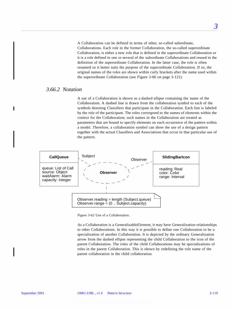
3
A Collaboration can be defined in terms of other, so-called subordinate, Collaborations. Each role in the former Collaboration, the so-called superordinate Collaboration, is either a new role that is defined in the superordinate Collaboration or it is a role defined in one or several of the subordinate Collaborations and reused in the definition of the superordinate Collaboration. In the latter case, the role is often renamed so it better suits the purpose of the superordinate Collaboration. If so, the original names of the roles are shown within curly brackets after the name used within the superordinate Collaboration (see Figure 3-66 on page 3-121).
3.66.2 Notation
A use of a Collaboration is shown as a dashed ellipse containing the name of the Collaboration. A dashed line is drawn from the collaboration symbol to each of the symbols denoting Classifiers that participate in the Collaboration. Each line is labeled by the role of the participant. The roles correspond to the names of elements within the context for the Collaboration; such names in the Collaboration are treated as parameters that are bound to specify elements on each occurrence of the pattern within a model. Therefore, a collaboration symbol can show the use of a design pattern together with the actual Classifiers and Associations that occur in that particular use of the pattern.
Figure 3-62 Use of a Collaboration.
As a Collaboration is a GeneralizableElement, it may have Generalization relationships to other Collaborations. In this way it is possible to define one Collaboration to be a specialization of another Collaboration. It is depicted by the ordinary Generalization arrow from the dashed ellipse representing the child Collaboration to the icon of the parent Collaboration. The roles of the child Collaborations may be specializations of roles in the parent Collaboration. This is shown by redefining the role name of the parent collaboration in the child collaboration.
Observer
SlidingBarIconObserver
CallQueue Subject
queue: List of Callsource: ObjectwaitAlarm: Alarm
reading: Realcolor: Colorrange: Interval
Observer.reading = length (Subject.queue)
capacity: Integer
Observer.range = (0 .. Subject.capacity)
September 2001 OMG-UML , v1.4 Pattern Structure 3-119
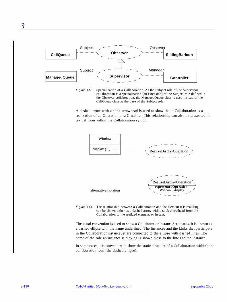
3
Figure 3-63 Specialization of a Collaboration. As the Subject role of the Supervisorcollaboration is a specialization (an extension) of the Subject role defined in the Observer collaboration, the ManagedQueue class is used instead of theCallQueue class as the base of the Subject role.
A dashed arrow with a stick arrowhead is used to show that a Collaboration is a realization of an Operation or a Classifier. This relationship can also be presented in textual form within the Collaboration symbol.
Figure 3-64 The relationship between a Collaboration and the element it is realizing can be shown either as a dashed arrow with a stick arrowhead from theCollaboration to the realized element, or in text.
The usual convention is used to show a CollaborationInstanceSet; that is, it is shown as a dashed ellipse with the name underlined. The Instances and the Links that participate in the CollaborationInstanceSet are connected to the ellipse with dashed lines. The name of the role an instance is playing is shown close to the line and the instance.
In some cases it is convenient to show the static structure of a Collaboration within the collaboration icon (the dashed ellipse).
Observer SlidingBarIcon
Observer
CallQueue
Subject
Supervisor Controller
Manager
ManagedQueue
Subject
Window
display (...)
representedOperation:alternative notation Window:: display
RealizeDisplayOperation
RealizeDisplayOperation
3-120 OMG-Unified Modeling Language, v1.4 September 2001

3
Figure 3-65 The static structure of a Collaboration shown within the collaboration icon.
It is possible to denote that a Collaboration is defined in terms of other Collaborations in two different ways, either using dashed ellipses showing the Collaborations and their relationships, or using ordinary collaboration diagrams. The former way has the advantage that it explicitly shows the relationship between the Collaborations, while the latter shows the structure of the new Collaboration.
Figure 3-66 The ComponentFramework Collaboration uses two occurrences of the ProxyCollaboration and two occurrences of the Container Collaboration. Note that eachrole in the Component Framework corresponds to a role in two of the usedCollaborations.
Observer
/Observer : SlidingBarIcon/Subject : CallQueue
Proxy
Component Framework
Proxy OriginalClient
«usedCollaboration»
Proxy
Proxy OriginalClient
Factory
Component
Component
Container
ElementContainer
Container
ElementContainer
Client Object
RemoteObject
ServiceContainer
«usedCollaboration»«usedCollaboration»
«usedCollaboration»
September 2001 OMG-UML , v1.4 Pattern Structure 3-121
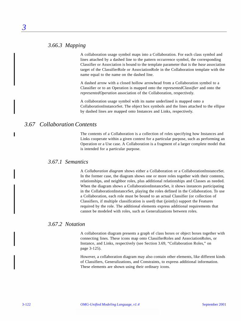
3
3.66.3 Mapping
A collaboration usage symbol maps into a Collaboration. For each class symbol and lines attached by a dashed line to the pattern occurrence symbol, the corresponding Classifier or Association is bound to the template parameter that is the base association target of the ClassifierRole or AssociationRole in the Collaboration template with the name equal to the name on the dashed line.
A dashed arrow with a closed hollow arrowhead from a Collaboration symbol to a Classifier or to an Operation is mapped onto the representedClassifier and onto the representedOperation association of the Collaboration, respectively.
A collaboration usage symbol with its name underlined is mapped onto a CollaborationInstanceSet. The object box symbols and the lines attached to the ellipse by dashed lines are mapped onto Instances and Links, respectively.
3.67 Collaboration Contents
The contents of a Collaboration is a collection of roles specifying how Instances and Links cooperate within a given context for a particular purpose, such as performing an Operation or a Use case. A Collaboration is a fragment of a larger complete model that is intended for a particular purpose.
3.67.1 Semantics
A Collaboration diagram shows either a Collaboration or a CollaborationInstanceSet. In the former case, the diagram shows one or more roles together with their contents, relationships, and neighbor roles, plus additional relationships and Classes as needed. When the diagram shows a CollaborationInstanceSet, it shows instances participating in the CollaborationInstanceSet, playing the roles defined in the Collaboration. To use a Collaboration, each role must be bound to an actual Classifier (or collection of Classifiers, if multiple classification is used) that (jointly) support the Features required by the role. The additional elements express additional requirements that cannot be modeled with roles, such as Generalizations between roles.
3.67.2 Notation
A collaboration diagram presents a graph of class boxes or object boxes together with connecting lines. These icons map onto ClassifierRoles and AssociationRoles, or Instance, and Links, respectively (see Section 3.69, “Collaboration Roles,” on page 3-125).
However, a collaboration diagram may also contain other elements, like different kinds of Classifiers, Generalizations, and Constraints, to express additional information. These elements are shown using their ordinary icons.
3-122 OMG-Unified Modeling Language, v1.4 September 2001
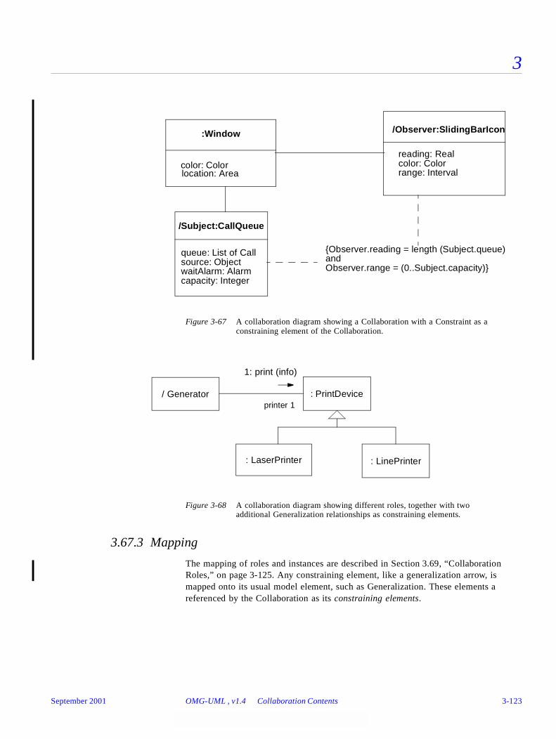
3
Figure 3-67 A collaboration diagram showing a Collaboration with a Constraint as a constraining element of the Collaboration.
Figure 3-68 A collaboration diagram showing different roles, together with two additional Generalization relationships as constraining elements.
3.67.3 Mapping
The mapping of roles and instances are described in Section 3.69, “Collaboration Roles,” on page 3-125. Any constraining element, like a generalization arrow, is mapped onto its usual model element, such as Generalization. These elements a referenced by the Collaboration as its constraining elements.
/Observer:SlidingBarIcon
/Subject:CallQueue
queue: List of Callsource: ObjectwaitAlarm: Alarm
reading: Realcolor: Colorrange: Interval
capacity: Integer
:Window
color: Colorlocation: Area
{Observer.reading = length (Subject.queue)andObserver.range = (0..Subject.capacity)}
/ Generator : PrintDevice
1: print (info)
: LaserPrinter : LinePrinter
printer 1
September 2001 OMG-UML , v1.4 Collaboration Contents 3-123
3
3.68 Interactions
A collaboration of Instances interacts to accomplish a purpose (such as performing an Operation) by exchanging Stimuli. These may include both sending Signals and invocations of Operations, as well as more implicit interaction through conditions and time events. A specific pattern of communication exchanges to accomplish a specific purpose is called an Interaction. The collection of Stimuli sent between the Instances that participate in a CollaborationInstanceSet when they perform the task of the Collaboration is called an InteractionInstanceSet.
3.68.1 Semantics
An Interaction is a behavioral specification that comprises a sequence of communications exchanged among a set of Instances within a Collaboration to accomplish a specific purpose, such as the implementation of an Operation. To specify an Interaction, it is first necessary to specify a Collaboration; that is, to establish the roles that interact and their relationships. Then, the possible interaction sequences are specified. These can be specified in a single description containing conditionals (branches or conditional signals), or they can be specified by supplying multiple descriptions, each describing a particular path through the possible execution paths.
One communication is specified with a Message; it specifies the sender and the receiver roles, as well as the Action that will cause the communication to take place. The Action specifies what kind of communication that should take place, such as sending a Signal or invoking an Operation, together with a sequence of expressions that determine the arguments to be supplied. The Action may also contain a recurrence expression stating a condition or an iteration of the performance of the Action.
When the Action is performed, a Stimulus is dispatched conforming to the Message. The Stimulus contains references to the sender and the receiver Instances playing the sender role and the receiver role of the Message, as well as a sequence of references to Instances being the result of evaluating the argument expressions of the dispatching Action. An InteractionInstanceSet is a collection of Stimuli that conform to the Messages of an Interaction; that is, the Stimuli are sent between the Instances participating in a CollaborationInstanceSet when they perform the task defined by the Collaboration.
3.68.2 Notation
Interactions are shown as sequence diagrams or as collaboration diagrams. Both diagram formats show the execution of collaborations. However, sequence diagrams do not show the relationships between the Instances or the Attribute values of the Instances; therefore, they do not fully show the context aspect of a Collaboration. Sequence diagrams do show the behavioral aspect of Collaborations explicitly, including the time sequence of Stimuli and explicit representation of method activations. Sequence diagrams are described in “Part 7 - Interaction Diagrams” on page 3-100. Collaboration diagrams show the full context of an interaction, including the Instances and their relationships relevant to a particular interaction. The sequencing of the Stimuli is done using sequence numbers, since distributing them along a time
3-124 OMG-Unified Modeling Language, v1.4 September 2001
3
axis, like in Sequence diagrams, is not possible in this kind of diagram. (In fact, in some cases it is convenient to use sequence numbers in combination with a time axis.) The contents of collaboration diagrams are described in the following section.
3.68.3 Mapping
The mapping of roles and instances are described below, while the mapping of messages and stimuli are described in Section 3.72, “Message and Stimulus,” on page 3-131.
3.68.4 Example
See Section 3.65, “Collaboration Diagram,” on page 3-115 for examples of Interactions and InteractionInstanceSets and their Collaborations and CollaborationInstanceSets, respectively.
3.69 Collaboration Roles
3.69.1 Semantics
A ClassifierRole defines a role to be played by an Instance within a Collaboration. The role describes the kind of Instance that may play the role, such as required Operations and Attributes, and describes its relationships to Instances playing other roles. The relationships to other roles are defined by AssociationRoles. These describe the required Links between the Instances; that is, a subset of the existing Links.
3.69.2 Notation
A ClassifierRole is shown using a class rectangle symbol. Normally, only the name compartment is shown, but the attribute and operation compartments may also be shown when needed. The name compartment contains the string:
‘/’ ClassifierRoleName ‘:’ ClassifierName [‘,’ ClassifierName]*
The name of the Classifier (or Classifiers if multiple classification is used) can include a full pathname of enclosing Packages, if necessary. A tool will normally permit shortened pathnames to be used when they are unambiguous. The Package names precede the Classifier name and are separated by double colons. For example:
display_window: WindowingSystem::GraphicWindows::Window
A stereotype may be shown textually (in guillemets above the name string) or as an icon in the upper right corner. A ClassifierRole representing a set of Instances can include a multiplicity indicator (such as “*”) in the upper right corner of the class box.
September 2001 OMG-UML , v1.4 Collaboration Roles 3-125
3
An AssociationRole is shown with the usual association line. The name string of the AssociationRole follows the same syntax as for the ClassifierRole. If the name is omitted, a line connected to ClassifierRole symbols denotes an AssociationRole. The information attached to the ends of the AssociationRole; that is, to the AssociationEndRoles, are shown using the same notation as for AssociationEnds.
An Instance playing the role defined by a ClassifierRole is depicted by an object box, normally without an attribute compartment. The name of the Instance is shown as a string:
ObjectName ‘/’ ClassifierRoleName ‘:’ ClassifierName [‘,’ ClassifierName]*
That is it starts with the name of the Instance, followed by the complete name of the ClassifierRole, all underlined. If the attribute compartment is shown, it contains the names of the Attributes required by an Instance playing the role. If some Attributes are required to have certain values, this is shown in the same way as in object diagrams; that is, the name of the attribute followed by an equal sign and the relevant values.
A Link is shown by a line between object boxes. Its name string follows the syntax of an Object playing a specific role.
3.69.3 Presentation options
The name of a ClassifierRole may be omitted. In this case, the colon is kept together with the Classifier name. The role name may be omitted only if there is only one role to be played by Instances of the base Classifier in the Collaboration.
The name of the Classifier may be omitted together with the colon.
At least one of the Classifier name (together with the colon) or the ClassifierRole name (together with the slash) must be present to denote a ClassifierRole. Otherwise, the rectangle denotes an ordinary Classifier or Instance depending on whether the name is underlined or not.
If the role is to be played by an Instance originating from multiple Classifiers, the names of the Classifiers are shown in a comma separated list after the colon.
In an object box the Instance name, the role name and / or the classifier name may be omitted. However, the colon should be kept in front of the classifier name, and the slash should be kept in front of the role name. The notation used is the same for Instances in general, with the possible addition of the name of the ClassifierRole that the Instance conforms to.
Note, the name of an Instance is always underlined, whereas the name of a Classifier (including ClassifierRole) is never underlined. Furthermore, an un-named line between icons representing Instances is always a Link, and between icons representing Classifiers (except ClassifierRoles) it is always an Association.
3-126 OMG-Unified Modeling Language, v1.4 September 2001
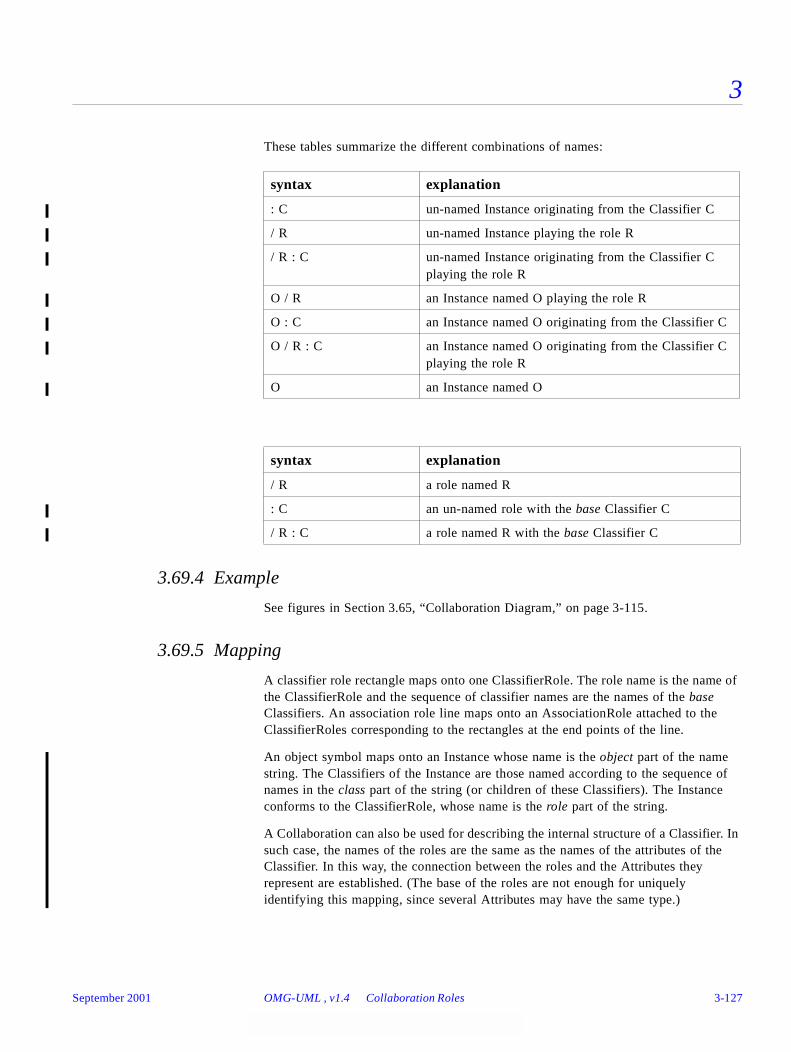
3
These tables summarize the different combinations of names:
3.69.4 Example
See figures in Section 3.65, “Collaboration Diagram,” on page 3-115.
3.69.5 Mapping
A classifier role rectangle maps onto one ClassifierRole. The role name is the name of the ClassifierRole and the sequence of classifier names are the names of the base Classifiers. An association role line maps onto an AssociationRole attached to the ClassifierRoles corresponding to the rectangles at the end points of the line.
An object symbol maps onto an Instance whose name is the object part of the name string. The Classifiers of the Instance are those named according to the sequence of names in the class part of the string (or children of these Classifiers). The Instance conforms to the ClassifierRole, whose name is the role part of the string.
A Collaboration can also be used for describing the internal structure of a Classifier. In such case, the names of the roles are the same as the names of the attributes of the Classifier. In this way, the connection between the roles and the Attributes they represent are established. (The base of the roles are not enough for uniquely identifying this mapping, since several Attributes may have the same type.)
syntax explanation
: C un-named Instance originating from the Classifier C
/ R un-named Instance playing the role R
/ R : C un-named Instance originating from the Classifier C playing the role R
O / R an Instance named O playing the role R
O : C an Instance named O originating from the Classifier C
O / R : C an Instance named O originating from the Classifier C playing the role R
O an Instance named O
syntax explanation
/ R a role named R
: C an un-named role with the base Classifier C
/ R : C a role named R with the base Classifier C
September 2001 OMG-UML , v1.4 Collaboration Roles 3-127

3
3.70 Multiobject
3.70.1 Semantics
A multiobject represents a set of Instances on the “many” end of an Association. This is used to show Operations and Signals that address the entire set, rather than a single Instance in it. The underlying static model is unaffected by this grouping. This corresponds to an Association with multiplicity “many” used to access a set of associated Instances.
3.70.2 Notation
A multiobject is shown as two rectangles in which the top rectangle is shifted slightly vertically and horizontally to suggest a stack of rectangles. A message arrow to the multiobject symbol indicates a Stimulus to the set of Instances (for example, a selection Operation to find an individual Object).
To perform an Operation on each Instance in a set of associated Instances requires two Stimuli: 1) an iteration to the multiobject to extract Links to the individual Instances and then 2) a Stimulus sent to each individual Instance using the (temporary) Link. This may be elided on a diagram by combining the arrows into a single arrow that includes an iteration and an application to each individual Instance. The target rolename takes a “many” indicator (*) to show that many individual Links are implied. Although this may be written as a single Stimulus, in the underlying model (and in any actual code) it requires the two layers of structure (iteration to find Links, communication using each Link) mentioned previously.
An Instance from the set is shown as a normal object symbol, but it may be attached to the multiobject symbol using a composition Link to indicate that it is part of the set. A communication arrow to the simple object symbol indicates a Stimulus to an individual Instance.
Typically a selection Stimulus to a multiobject returns a reference to an individual Instance, to which the original sender then sends a Stimulus.
3-128 OMG-Unified Modeling Language, v1.4 September 2001
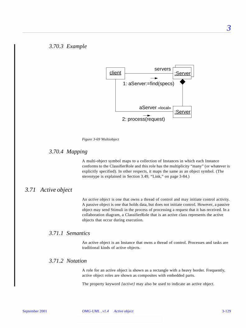
3
3.70.3 Example
Figure 3-69 Multiobject
3.70.4 Mapping
A multi-object symbol maps to a collection of Instances in which each Instance conforms to the ClassifierRole and this role has the multiplicity “many” (or whatever is explicitly specified). In other respects, it maps the same as an object symbol. (The stereotype is explained in Section 3.49, “Link,” on page 3-84.)
3.71 Active object
An active object is one that owns a thread of control and may initiate control activity. A passive object is one that holds data, but does not initiate control. However, a passive object may send Stimuli in the process of processing a request that it has received. In a collaboration diagram, a ClassifierRole that is an active class represents the active objects that occur during execution.
3.71.1 Semantics
An active object is an Instance that owns a thread of control. Processes and tasks are traditional kinds of active objects.
3.71.2 Notation
A role for an active object is shown as a rectangle with a heavy border. Frequently, active object roles are shown as composites with embedded parts.
The property keyword {active} may also be used to indicate an active object.
servers:Server
:ServeraServer «local»
client
1: aServer:=find(specs)
2: process(request)
September 2001 OMG-UML , v1.4 Active object 3-129

3
3.71.3 Example
Figure 3-70 Composite Active Object
3.71.4 Mapping
An active object symbol maps as an object symbol does, with the addition that the class of the object has the active property set.
job
:FactoryJobMgr
:FactoryScheduler
currentJob : TransferJob
:Factory Manager
1: start(job)
A2,B2 / 2: completed(job)
«local» job
:Oven:Robot
1 / A1: start(job)1 / B1: start(job)
A2: completedB2: completed
3-130 OMG-Unified Modeling Language, v1.4 September 2001
3
3.72 Message and Stimulus
3.72.1 Semantics
In a collaboration diagram a Stimulus is a communication between two Instances that conveys information with the expectation that action will ensue. A Stimulus will cause an Operation to be invoked, raise a Signal, or an Instance to be created or destroyed.
A Message is a specification of Stimulus. That is it specifies the roles that the sender and the receiver Instances should conform to, as well as the Action that will, when executed, dispatch a Stimulus that conforms to the Message.
3.72.2 Notation
Messages and Stimuli are shown as labeled arrows placed near an AssociationRole or a Link, respectively. The meaning is that the Link is used for transportation of the Stimulus to the target Instance. The arrow points along the line in the direction of the receiving Instance.
3.72.2.1 Control flow type
The following arrowhead variations may be used to show different kinds of communications.
filled solid arrowhead
Procedure call or other nested flow of control. The entire nested sequence is completed before the outer level sequence resumes. The arrowhead may be used to denote ordinary procedure calls, but it may also be used to denote concurrently active instances when one of them sends a Signal and waits for a nested sequence of behavior to complete before it continues.
stick arrowhead
Asynchronous communication; that is, no nesting of control. The sender dispatches the Stimulus and immediately continues with the next step in the execution.
dashed arrow with stick arrowhead
Return from a procedure call. The return arrow may be suppressed as it is implicit at the end of an activation.
other variations
Other kinds of control may be shown, such as “balking” or “time-out;” however, these are treated as extensions to the UML core.
September 2001 OMG-UML , v1.4 Message and Stimulus 3-131

3
A half stick arrowhead can be used to show asynchronous communication. This alternative is included for backwards compatibility. UML 1.3 and previous versions, included both half stick arrowhead and stick arrowhead with a very small (and not well-understood) distinction.
3.72.2.2 Arrow label
In the following the term Message is used, but the text applies to Stimulus, as well.
The label has the following syntax:
predecessor sequence-expression return-value := message-name argument-list
The label indicates the Message being sent, its arguments and return values, and the sequencing of the Message within the larger interaction, including call nesting, iteration, branching, concurrency, and synchronization.
3.72.2.3 Predecessor
The predecessor is a comma-separated list of sequence numbers followed by a slash (‘/’):
sequence-number ‘,’ . . . ‘/’
The clause is omitted if the list is empty.
Each sequence-number is a sequence-expression without any recurrence terms. It must match the sequence number of another Message.
The meaning is that the Message is not enabled until all of the communications whose sequence numbers appear in the list have occurred. Therefore, the list of predecessors represents a synchronization of threads.
Note that the Message corresponding to the numerically preceding sequence number is an implicit predecessor and need not be explicitly listed. All of the sequence numbers with the same prefix form a sequence. The numerical predecessor is the one in which the final term is one less. That is, number 3.1.4.5 is the predecessor of 3.1.4.6.
3.72.2.4 Sequence expression
The sequence-expression is a dot-separated list of sequence-terms followed by a colon (‘:’).
sequence-term ‘.’ . . . ‘:’
Each term represents a level of procedural nesting within the overall interaction. If all the control is concurrent, then nesting does not occur. Each sequence-term has the following syntax:
[ integer | name ] [ recurrence ]
3-132 OMG-Unified Modeling Language, v1.4 September 2001
3
The integer represents the sequential order of the Message within the next higher level of procedural calling. Messages that differ in one integer term are sequentially related at that level of nesting. Example: Message 3.1.4 follows Message 3.1.3 within activation 3.1. The name represents a concurrent thread of control. Messages that differ in the final name are concurrent at that level of nesting. Example: Message 3.1a and Message 3.1b are concurrent within activation 3.1. All threads of control are equal within the nesting depth.
The recurrence represents conditional or iterative execution. This represents zero or more Messages that are executed depending on the conditions involved. The choices are:
‘*’ ‘[’ iteration-clause ‘]’an iteration
‘[’ condition-clause ‘]’a branch
An iteration represents a sequence of Messages at the given nesting depth. The iteration clause may be omitted (in which case the iteration conditions are unspecified). The iteration-clause is meant to be expressed in pseudocode or an actual programming language, UML does not prescribe its format. An example would be: *[i := 1..n].
A condition represents a Message whose execution is contingent on the truth of the condition clause. The condition-clause is meant to be expressed in pseudocode or an actual programming language; UML does not prescribe its format. An example would be: [x > y].
Note that a branch is notated the same as an iteration without a star. One might think of it as an iteration restricted to a single occurrence.
The iteration notation assumes that the Messages in the iteration will be executed sequentially. There is also the possibility of executing them concurrently. The notation for this is to follow the star by a double vertical line (for parallelism): *||.
Note that in a nested control structure, the recurrence is not repeated at inner levels. Each level of structure specifies its own iteration within the enclosing context.
3.72.2.5 Signature
A signature is a string that indicates the name, the arguments, and the return value of an Operation or a Reception. The signature of a Message is derived from (is the same as) the signature of the Operation attached to the Message's dispatching Action, or the Reception for the Signal attached to the action. These have the following properties.
Return-value
This is a list of names that designates the values returned at the end of the communication within the subsequent execution of the overall interaction. These identifiers can be used as arguments to subsequent Messages. If the Message does not return a value, then the return value and the assignment operator are omitted.
September 2001 OMG-UML , v1.4 Message and Stimulus 3-133
3
Message-name
This is the name of the Operation to be applied on the receiver, or the Signal that is sent to the receiver.
Argument list
This is a comma-separated list of arguments (actual parameters) enclosed in parentheses. The parentheses can be used even if the list is empty. Each argument is either a reference to an Instance, or an expression in pseudocode or an appropriate programming language (UML does not prescribe). The expressions may use return values of previous messages (in the same scope) and navigation expressions starting from the source Instance; that is, Attributes of it and Links from it and paths reachable from them.
3.72.3 Presentation Options
Instead of text expressions for arguments and return values, data tokens may be shown near a message label. A token is a small circle labeled with the argument expression or return value name. It has a small arrow on it that points along the Message (for an argument) or opposite the Message (for a return value). Tokens represent arguments and return values. The choice of text syntax or tokens is a presentation option.
The syntax of Messages may instead be expressed in the syntax of a programming language, such as C++ or Smalltalk. All of the expressions on a single diagram should use the same syntax, however.
A return flow may be explicitly shown with a dashed arrow.
3.72.4 Example
See Figure 3-59 on page 3-117 for examples within a diagram.
Samples of control message label syntax:
2: display (x, y)simple Message
1.3.1: p:= find(specs)nested call with return value
4 [x < 0] : invert (x, color)conditional Message
A3,B4/ C3.1*: update ()synchronization with other threads, iteration
3.72.5 Mapping
An arrow symbol maps either onto a Message or a Stimulus. If the arrow is attached to a line corresponding to an AssociationRole, it maps onto a Message, with the ClassifierRoles corresponding to the end-points of the line as the sender and the receiver roles. If the line corresponds to a Link, the arrow maps onto a Stimulus, with
3-134 OMG-Unified Modeling Language, v1.4 September 2001
3
the Instances corresponding to the end-points of the line as the sender and the receiver Instances. The line is the communication connection or the communication link of the Message or the Stimulus, respectively.
The control flow type sets the corresponding properties:
• solid arrowhead: a synchronous operation invocation
• stick arrowhead: an asynchronous operation invocation
• dashed arrow with stick arrowhead: return from an synchronous operation invocation
The predecessor expression, together with the sequence expression, determines the predecessor and activation (caller) relationships of a Message or a Stimulus. The predecessors of a Message (Stimulus) are those Messages (Stimuli) corresponding to the sequence numbers in the predecessor list as well as the Message (Stimulus) corresponding to the immediate preceding sequence number as the Message (Stimulus); that is, 1.2.2 is the one preceding 1.2.3. The caller is the ClassifierRole (Instance) receiving the Message (Stimulus) whose sequence number is truncated by one position; that is, 1.2 is the caller of 1.2.3. The thread-of-control name maps onto a Classifier stereotyped thread; that is, an active class.
The return of a value maps into a Message from the called Instance to the caller with the dispatching Action being a ReturnAction. Its predecessor is the final Message within the procedure. Its activation is the Message that called the procedure.
The recurrence expression, the iteration clause, and the condition clause determine the recurrence value in the Action attached to the Message.
The operation name and the form of the signature determine the Operation attached to the CallAction associated with the Message. Similarly for a Signal and SendAction. The arguments of the signature determine the arguments associated with the CallAction and SendAction, respectively.
In a procedural interaction, each arrow symbol also maps into a second Message representing the return flow, unless the return flow is explicitly shown. This Message has an activation Association to the original call Message. Its associated Action is a ReturnAction bearing the return values as arguments (if any).
3.73 Creation/Destruction Markers
3.73.1 Semantics
During the execution of an interaction some Instances and Links are created and some are destroyed. The creation and destruction of elements can be marked.
September 2001 OMG-UML , v1.4 Creation/Destruction Markers 3-135

3
3.73.2 Notation
An Instance or a Link that is created during an interaction has the standard constraint new attached to it. An Instance or a Link that is destroyed during an interaction has the standard constraint destroyed attached. These constraints may be used even if the element has no name. Both constraints may be used together, but the standard constraint transient may be used in place of new destroyed.
3.73.3 Presentation options
Tools may use other graphic markers in addition to or in place of the keywords. For example, each kind of lifetime might be shown in a different color. A tool may also use animation to show the creation and destruction of elements and the state of the system at various times.
3.73.4 Example
See Figure 3-59 on page 3-117.
3.73.5 Mapping
Creation or destruction indicators map either into CreateActions, DestroyActions, or TerminateActions in the corresponding ClassifierRoles. The former two Actions dispatch the Stimuli that cause the changes. These status indicators are merely summaries of the total actions.
Part 9 - Statechart DiagramsA statechart diagram can be used to describe the behavior of instances of a model element such as an object or an interaction. Specifically, it describes possible sequences of states and actions through which the element instances can proceed during its lifetime as a result of reacting to discrete events (for example, signals, operation invocations).
The semantics and notation described in this chapter are substantially those of David Harel’s statecharts with modifications to make them object-oriented. His work was a major advance on the traditional flat state machines. Statechart notation also implements aspects of both Moore machines and Mealy machines, traditional state machine models.
3-136 OMG-Unified Modeling Language, v1.4 September 2001
3
3.74 Statechart Diagram
3.74.1 Semantics
Statechart diagrams represent the behavior of entities capable of dynamic behavior by specifying its response to the receipt of event instances. Typically, it is used for describing the behavior of class instances, but statecharts may also describe the behavior of other entities such as use-cases, actors, subsystems, operations, or methods.
3.74.2 Notation
A statechart diagram is a graph that represents a state machine. States and various other types of vertices (pseudostates) in the state machine graph are rendered by appropriate state and pseudostate symbols, while transitions are generally rendered by directed arcs that inter-connect them. States may also contain subdiagrams by physical containment or tiling. Note that every state machine has a top state that contains all the other elements of the entire state machine. The graphical rendering of this top state is optional.
The association between a state machine and its context does not have a special notation.
An example statechart diagram for a simple telephone object is depicted in Figure 3-71 on page 3-138.
September 2001 OMG-UML , v1.4 Statechart Diagram 3-137
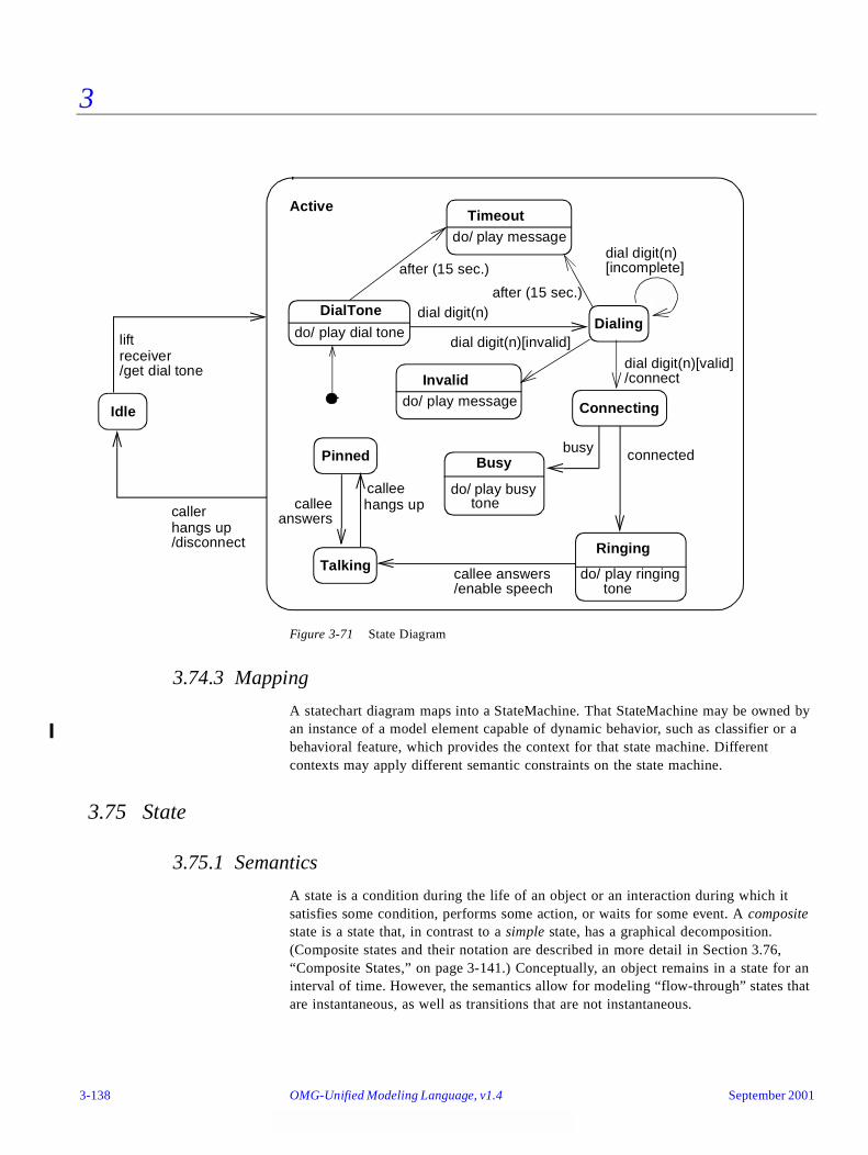
3
Figure 3-71 State Diagram
3.74.3 Mapping
A statechart diagram maps into a StateMachine. That StateMachine may be owned by an instance of a model element capable of dynamic behavior, such as classifier or a behavioral feature, which provides the context for that state machine. Different contexts may apply different semantic constraints on the state machine.
3.75 State
3.75.1 Semantics
A state is a condition during the life of an object or an interaction during which it satisfies some condition, performs some action, or waits for some event. A composite state is a state that, in contrast to a simple state, has a graphical decomposition. (Composite states and their notation are described in more detail in Section 3.76, “Composite States,” on page 3-141.) Conceptually, an object remains in a state for an interval of time. However, the semantics allow for modeling “flow-through” states that are instantaneous, as well as transitions that are not instantaneous.
DialToneDialing
TalkingRinging
Busy
dial digit(n)
connected
callee answers
Idle
busy
liftreceiver
callerhangs up
calleehangs up
Active
dial digit(n)
/get dial tone
do/ play busytone
do/ play ringingtone/enable speech
/disconnect
do/ play dial tone
Pinned
calleeanswers
Connecting
dial digit(n)[valid]
Timeoutdo/ play message
dial digit(n)[invalid]
/connectInvaliddo/ play message
[incomplete]after (15 sec.)
after (15 sec.)
3-138 OMG-Unified Modeling Language, v1.4 September 2001
3
A state may be used to model an ongoing activity. Such an activity is specified either by a nested state machine or by a computational expression.
3.75.2 Notation
A state is shown as a rectangle with rounded corners (Figure 3-72 on page 3-140). Optionally, it may have an attached name tab. The name tab is a rectangle, usually resting on the outside of the top side of a state and it contains the name of that state. It is normally used to keep the name of a composite state that has concurrent regions, but may be used in other cases as well (the Process state in Figure 3-77 on page 3-148 illustrates the use of the name tab).
A state may be optionally subdivided into multiple compartments separated from each other by a horizontal line. They are as follows:
• Name compartment
This compartment holds the (optional) name of the state as a string. States without names are anonymous and are all distinct. It is undesirable to show the same named state twice in the same diagram, as confusion may ensue. Name compartments should not be used if a name tab is used and vice versa.
• Internal transitions compartment
This compartment holds a list of internal actions or activities that are performed while the element is in the state.
The action label identifies the circumstances under which the action specified by the action expression will be invoked. The action expression may use any attributes and links that are in the scope of the owning entity. For list items where the action expression is empty, the backslash separator is optional.
A number of action labels are reserved for various special purposes and, therefore, cannot be used as event names. The following are the reserved action labels and their meaning:
• entry
This label identifies an action, specified by the corresponding action expression, which is performed upon entry to the state (entry action).
• exit
This label identifies an action, specified by the corresponding action expression, that is performed upon exit from the state (exit action).
• do
This label identifies an ongoing activity (“do activity”) that is performed as long as the modeled element is in the state or until the computation specified by the action expression is completed (the latter may result in a completion event being generated).
September 2001 OMG-UML , v1.4 State 3-139

3
• include
This label is used to identify a submachine invocation. The action expression contains the name of the submachine that is to be invoked. Submachine states and the corresponding notation are described in Section 3.82, “Submachine States,” on page 3-153.
In all other cases, the action label identifies the event that triggers the corresponding action expression. These events are called internal transitions and are semantically equivalent to self transitions except that the state is not exited or re-entered. This means that the corresponding exit and entry actions are not performed. The general format for the list item of an internal transition is:
event-name ‘(’ comma-separated-parameter-list ‘)’ ‘[’ guard-condition‘]’ ‘/’ action-expression
Each event name may appear more than once per state if the guard conditions are different. The event parameters and the guard conditions are optional. If the event has parameters, they can be used in the action expression through the current event variable.
3.75.3 Example
Figure 3-72 State
3.75.4 Mapping
A state symbol maps into a State. See Section 3.76, “Composite States,” on page 3-141 for further details on which kind of state.
The name string in the symbol maps to the name of the state. Two symbols with the same name map into the same state. However, each state symbol with no name (or an empty name string) maps into a distinct anonymous State.
A list item in the internal transition compartment maps into a corresponding Action associated with a state. An “entry” list item; that is, an item with the “entry” label maps to the “entry” role, an “exit” list item maps to the “exit” role, and a “do” item maps to the “doActivity” role. (The mapping of “include” items is discussed in Section 3.82, “Submachine States,” on page 3-153.)
Typing Password
help / display help
entry / set echo invisibleexit / set echo normalcharacter / handle character
3-140 OMG-Unified Modeling Language, v1.4 September 2001
3
A list item with an event name maps to a Transition associated with the “internal” role relative to the state. The action expression maps into the ActionSequence and Guard for the Transition. The event name and arguments map into an Event corresponding to the event name and arguments. The Event plays the role of a trigger to the Transition.
3.76 Composite States
3.76.1 Semantics
A composite state is decomposed into two or more concurrent substates (called regions) or into mutually exclusive disjoint substates. A given state may only be refined in one of these two ways. Naturally, any substate of a composite state can also be a composite state of either type.
A newly-created object takes its topmost default transition, originating from the topmost initial pseudostate. An object that transitions to its outermost final state is terminated.
Each region of a state may have initial pseudostates and final states. A transition to the enclosing state represents a transition to the initial pseudostate. A transition to a final state represents the completion of activity in the enclosing region. Completion of activity in all concurrent regions represents completion of activity by the enclosing state and triggers a completion event on the enclosing state. Completion of the top state of an object corresponds to its termination.
3.76.2 Notation
An expansion of a state shows its internal state machine structure. In addition to the (optional) name and internal transition compartments, the state may have an additional compartment that contains a region holding a nested diagram. For convenience and appearance, the text compartments may be shrunk horizontally within the graphic region.
An expansion of a state into concurrent substates is shown by tiling the graphic region of the state using dashed lines to divide it into regions. Each region is a concurrent substate. Each region may have an optional name and must contain a nested state diagram with disjoint states. The text compartments of the entire state are separated from the concurrent substates by a solid line. It is also possible to use a tab notation to place the name of a concurrent state. The tab notation is more space efficient.
An expansion of a state into disjoint substates is shown by showing a nested state diagram within the graphic region.
An initial pseudostate is shown as a small solid filled circle. In a top-level state machine, the transition from an initial pseudostate may be labeled with the event that creates the object; otherwise, it must be unlabeled. If it is unlabeled, it represents any transition to the enclosing state. The initial transition may have an action.
September 2001 OMG-UML , v1.4 Composite States 3-141
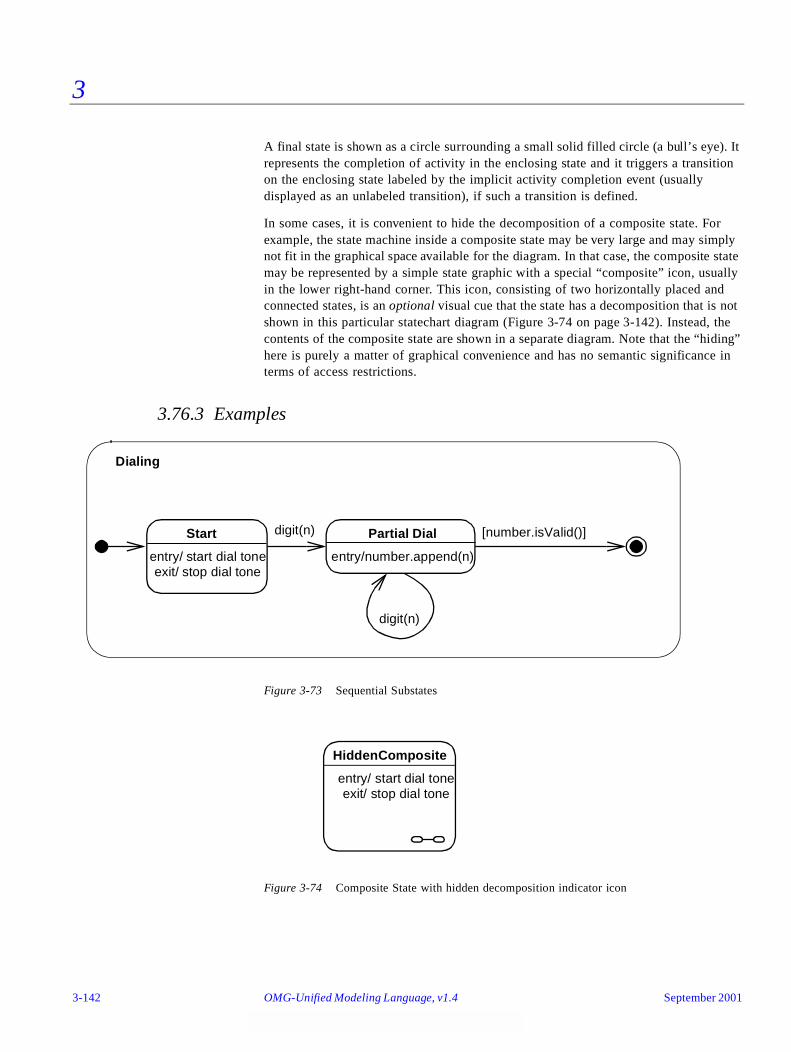
3
A final state is shown as a circle surrounding a small solid filled circle (a bull’s eye). It represents the completion of activity in the enclosing state and it triggers a transition on the enclosing state labeled by the implicit activity completion event (usually displayed as an unlabeled transition), if such a transition is defined.
In some cases, it is convenient to hide the decomposition of a composite state. For example, the state machine inside a composite state may be very large and may simply not fit in the graphical space available for the diagram. In that case, the composite state may be represented by a simple state graphic with a special “composite” icon, usually in the lower right-hand corner. This icon, consisting of two horizontally placed and connected states, is an optional visual cue that the state has a decomposition that is not shown in this particular statechart diagram (Figure 3-74 on page 3-142). Instead, the contents of the composite state are shown in a separate diagram. Note that the “hiding” here is purely a matter of graphical convenience and has no semantic significance in terms of access restrictions.
3.76.3 Examples
Figure 3-73 Sequential Substates
Figure 3-74 Composite State with hidden decomposition indicator icon
Start
entry/ start dial tone
Partial Dial
entry/number.append(n)
digit(n)
digit(n)
[number.isValid()]
Dialing
exit/ stop dial tone
HiddenComposite
entry/ start dial toneexit/ stop dial tone
3-142 OMG-Unified Modeling Language, v1.4 September 2001

3
Figure 3-75 Concurrent Substates
3.76.4 Mapping
A state symbol maps into a State. If the symbol has no subdiagrams in it, it maps into a SimpleState. If it is tiled by dashed lines into regions, then it maps into a CompositeState with the isConcurrent value true; otherwise, it maps into a CompositeState with the isConcurrent value false. A region maps into a CompositeState with the isRegion value true and the isConcurrent value false.
An initial pseudostate symbol maps into a Pseudostate of kind initial. A final state symbol maps to a final state.
3.77 Events
3.77.1 Semantics
An event is a noteworthy occurrence. For practical purposes in state diagrams, it is an occurrence that may trigger a state transition. Events may be of several kinds (not necessarily mutually exclusive).
Lab1 Lab2
Term
lab done
project done
Passed
Incomplete
Project
Final pass
Test
Failedfail
lab done
Taking Class
September 2001 OMG-UML , v1.4 Events 3-143

3
• A designated condition becoming true (described by a Boolean expression) results in a change event instance. The event occurs whenever the value of the expression changes from false to true. Note that this is different from a guard condition. A guard condition is evaluated once whenever its event fires. If it is false, then the transition does not occur and the event is lost.
• The receipt of an explicit signal from one object to another results in a signal event instance. It is denoted by the signature of the event as a trigger on a transition.
• The receipt of a call for an operation implemented as a transition by an object represents a call event instance.
• The passage of a designated period of time after a designated event (often the entry of the current state) or the occurrence of a given date/time is a TimeEvent.
The event declaration has scope within the package it appears in and may be used in state diagrams for classes that have visibility inside the package. An event is not local to a single class.
3.77.2 Notation
A signal or call event can be defined using the following format:
event-name ‘(‘ comma-separated-parameter-list ‘)
A parameter has the format:
parameter-name ‘:’ type-expression
A signal can be declared using the «signal» keyword on a class symbol in a class diagram. The parameters are specified as attributes. A signal can be specified as a subclass of another signal. This indicates that an occurrence of the subevent triggers any transition that depends on the event or any of its ancestors.
An elapsed-time event can be specified with the keyword after followed by an expression that evaluates (at modeling time) to an amount of time, such as “after (5 seconds)” or after (10 seconds since exit from state A).” If no starting point is indicated, then it is the time since the entry to the current state. Other time events can be specified as conditions, such as when (date = Jan. 1, 2000).
A condition becoming true is shown with the keyword when followed by a Boolean expression. This may be regarded as a continuous test for the condition until it is true, although in practice it would only be checked on a change of values.
Signals can be declared on a class diagram with the keyword «signal» on a rectangle symbol. These define signal names that may be used to trigger transitions. Their parameters are shown in the attribute compartment. They have no operations. They may appear in a generalization hierarchy.
3-144 OMG-Unified Modeling Language, v1.4 September 2001
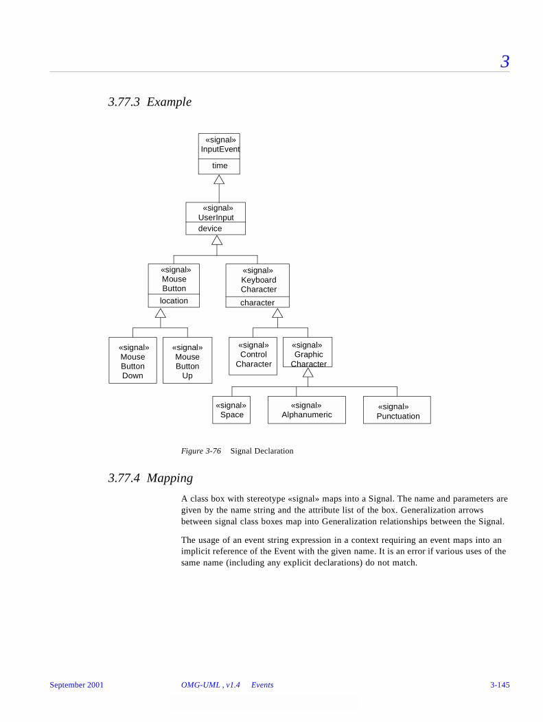
3
3.77.3 Example
Figure 3-76 Signal Declaration
3.77.4 Mapping
A class box with stereotype «signal» maps into a Signal. The name and parameters are given by the name string and the attribute list of the box. Generalization arrows between signal class boxes map into Generalization relationships between the Signal.
The usage of an event string expression in a context requiring an event maps into an implicit reference of the Event with the given name. It is an error if various uses of the same name (including any explicit declarations) do not match.
UserInputdevice
Mouse
location
ButtonKeyboardCharacter
character
InputEvent
time
Control Graphic
PunctuationAlphanumericSpace
Mouse MouseButtonDown
ButtonUp
«signal»
«signal»
«signal» «signal»
«signal» «signal» «signal»
«signal» «signal»
«signal»
«signal»
Character Character
September 2001 OMG-UML , v1.4 Events 3-145
3
3.78 Simple Transitions
3.78.1 Semantics
A simple transition is a relationship between two states indicating that an instance in the first state will enter the second state and perform specific actions when a specified event occurs provided that certain specified conditions are satisfied. On such a change of state, the transition is said to “fire.” The trigger for a transition is the occurrence of the event labeling the transition. The event may have parameters, which are accessible by the actions specified on the transition as well as in the corresponding exit and entry actions associated with the source and target states respectively. Events are processed one at a time. If an event does not trigger any transition, it is discarded. If it can trigger more than one transition within the same sequential region; that is, not in different concurrent regions, only one will fire. If these conflicting transitions are of the same priority, an arbitrary one is selected and triggered.
3.78.2 Notation
A transition is shown as a solid line originating from the source state and terminated by an arrow on the target state. It may be labeled by a transition string that has the following general format:
event-signature ‘[’ guard-condition ‘]’ ‘/’ action-expression
The event-signature describes an event with its arguments:
event-name ‘(’ comma-separated-parameter-list ‘)’
The guard-condition is a Boolean expression written in terms of parameters of the triggering event and attributes and links of the object that owns the state machine. The guard condition may also involve tests of concurrent states of the current machine, or explicitly designated states of some reachable object (for example, “in State1” or “not in State2”). State names may be fully qualified by the nested states that contain them, yielding pathnames of the form “State1::State2::State3.” This may be used in case same state name occurs in different composite state regions of the overall machine.
The action-expression is executed if and when the transition fires. It may be written in terms of operations, attributes, and links of the owning object and the parameters of the triggering event, or any other features visible in its scope. The corresponding action must be executed entirely before any other actions are considered. This model of execution is referred to as run-to-completion semantics. The action expression may be an action sequence comprising a number of distinct actions including actions that explicitly generate events, such as sending signals or invoking operations. The details of this expression are dependent on the action language chosen for the model.
3.78.2.1 Transition times
Names may be placed on transitions to designate the times at which they fire. See Section 3.64, “Transition Times,” on page 3-114.
3-146 OMG-Unified Modeling Language, v1.4 September 2001
3
3.78.3 Example
right-mouse-down (location) [location in window] / object := pick-object (location);object.highlight ()
The event may be any of the standard event types. Selecting the type depends on the syntax of the name (for time events, for example); however, SignalEvents and CallEvents are not distinguishable by syntax and must be discriminated by their declaration elsewhere.
3.78.4 Mapping
A transition string and the transition arrow that it labels together map into a Transition and its attachments. The arrow connects two state symbols. The Transition has the corresponding States as its source (the state at the tail) and destination (the state at the head) States in associations to the Transition.
The event name and parameters map into an Event element, which may be a SignalEvent, a CallEvent, a TimeExpression (if it has the proper syntax), or a ChangeEvent (if it is expressed as a Boolean expression). The event is attached as a “trigger” role in the association to the transition.
The guard condition maps into a Guard element attached to the Transition. Note that a guard condition is distinguished graphically from a change event specification by being enclosed in brackets.
An action expression maps into an Action attached as an “effect” role relative to the Transition.
3.79 Transitions to and from Concurrent States
A concurrent transition may have multiple source states and target states. It represents a synchronization and/or a splitting of control into concurrent threads without concurrent substates.
3.79.1 Semantics
A concurrent transition is enabled when all the source states are occupied. After a compound transition fires, all its destination states are occupied.
3.79.2 Notation
A concurrent transition includes a short heavy bar (a synchronization bar, which can represent synchronization, forking, or both). The bar may have one or more arrows from states to the bar (these are the source states). The bar may have one or more arrows from the bar to states (these are the destination states). A transition string may be shown near the bar. Individual arrows do not have their own transition strings.
September 2001 OMG-UML , v1.4 Transitions to and from Concurrent States 3-147
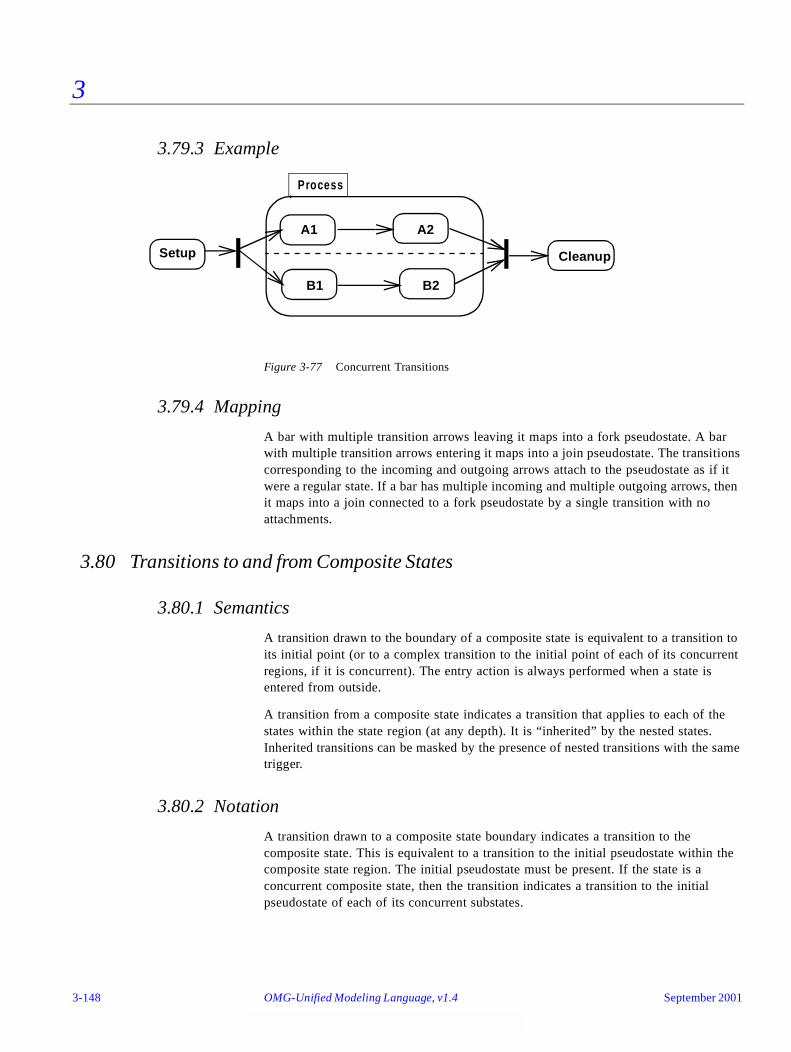
3
3.79.3 Example
Figure 3-77 Concurrent Transitions
3.79.4 Mapping
A bar with multiple transition arrows leaving it maps into a fork pseudostate. A bar with multiple transition arrows entering it maps into a join pseudostate. The transitions corresponding to the incoming and outgoing arrows attach to the pseudostate as if it were a regular state. If a bar has multiple incoming and multiple outgoing arrows, then it maps into a join connected to a fork pseudostate by a single transition with no attachments.
3.80 Transitions to and from Composite States
3.80.1 Semantics
A transition drawn to the boundary of a composite state is equivalent to a transition to its initial point (or to a complex transition to the initial point of each of its concurrent regions, if it is concurrent). The entry action is always performed when a state is entered from outside.
A transition from a composite state indicates a transition that applies to each of the states within the state region (at any depth). It is “inherited” by the nested states. Inherited transitions can be masked by the presence of nested transitions with the same trigger.
3.80.2 Notation
A transition drawn to a composite state boundary indicates a transition to the composite state. This is equivalent to a transition to the initial pseudostate within the composite state region. The initial pseudostate must be present. If the state is a concurrent composite state, then the transition indicates a transition to the initial pseudostate of each of its concurrent substates.
Process
Setup Cleanup
A1 A2
B2B1
3-148 OMG-Unified Modeling Language, v1.4 September 2001
3
Transitions may be drawn directly to states within a composite state region at any nesting depth. All entry actions are performed for any states that are entered on any transition. On a transition within a concurrent composite state, transition arrows from the synchronization bar may be drawn to one or more concurrent states. Any other concurrent regions start with their default initial pseudostate.
A transition drawn from a composite state boundary indicates a transition of the composite state. If such a transition fires, any nested states are forcibly terminated and perform their exit actions, then the transition actions occur and the new state is established.
Transitions may be drawn directly from states within a composite state region at any nesting depth to outside states. All exit actions are performed for any states that are exited on any transition. On a transition from within a concurrent composite state, transition arrows may be specified from one or more concurrent states to a synchronization bar; therefore, specific states in the other regions are irrelevant to triggering the transition.
A state region may contain a history state indicator shown as a small circle containing an ‘H.’ The history indicator applies to the state region that directly contains it. A history indicator may have any number of incoming transitions from outside states. It may have at most one outgoing unlabeled transition. This identifies the default “previous state” if the region has never been entered. If a transition to the history indicator fires, it indicates that the object resumes the state it last had within the composite region. Any necessary entry actions are performed. The history indicator may also be ‘H*’ for deep history. This indicates that the object resumes the state it last had at any depth within the composite region, rather than being restricted to the state at the same level as the history indicator. A region may have both shallow and deep history indicators.
3.80.3 Presentation Options
3.80.3.1 Stubbed transitions
Nested states may be suppressed. Transitions to nested states are subsumed to the most specific visible enclosing state of the suppressed state. Subsumed transitions that do not come from an unlabeled final state or go to an unlabeled initial pseudostate may (but need not) be shown as coming from or going to stubs. A stub is shown as a small vertical line (bar) drawn inside the boundary of the enclosing state. It indicates a transition connected to a suppressed internal state. Stubs are not used for transitions to initial or from final states.
Note that events should be shown on transitions leading into a state, either to the state boundary or to an internal substate, including a transition to a stubbed state. Normally events should not be shown on transitions leading from a stubbed state to an external state. Think of a transition as belonging to its source state. If the source state is suppressed, then so are the details of the transition. Note also that a transition from a final state is summarized by an unlabeled transition from the composite state contour (denoting the implicit event “action complete” for the corresponding state).
September 2001 OMG-UML , v1.4 Transitions to and from Composite States 3-149

3
3.80.4 Example
See Figure 3-76 on page 3-145 and Figure 3-77 on page 3-148 for examples of composite transitions. The following are examples of stubbed transitions and the history indicator.
Figure 3-78 Stubbed Transitions
Figure 3-79 History Indicator
A C
A C
BD
E
F
p s
t
B
r
p
r
D
W
W
may be abstracted as
u
s
s
A C
H
A1
A2
interrupt
resume
3-150 OMG-Unified Modeling Language, v1.4 September 2001

3
3.80.5 Mapping
An arrow to any state boundary, nested or not, maps into a Transition between the corresponding States and similarly for transitions directly to history states.
A history indicator maps into a Pseudostate of kind shallowHistory or deepHistory.
A stubbed transition does not map into anything in the model. It is a notational elision that indicates the presence of transitions to additional states in the model that are not visible in the diagram.
3.81 Factored Transition Paths
3.81.1 Semantics
By definition, a transition connects exactly two vertices in the state machine graph. However, since some of these vertices may be pseudostates—which are transient in nature—there is a need for describing chains of transitions that may be executed in the context of a single run-to-completion step. Such a transition is known as a compound transition.
As a practical measure, it is often useful to share segments of a compound transition. For example, two or more distinct compound transitions may come together and continue via a common path, sharing its action, and possibly terminating on the same target state. In other cases, it may be useful to split a transition into separate mutually exclusive; that is, non-concurrent paths.
Both of these examples of graphical factoring in which some transitions are shared result in simplified diagrams. However, factoring is also useful for modeling dynamically adaptive behavior. An example of this occurs when a single event may lead to any of a set of possible target states, but where the final target state is only determined as the result of an action (calculation) performed after the triggering of the compound transition.
Note that the splitting and joining of paths due to factoring is different from the splitting and joining of concurrent transitions described in Sect i on3.79, “Transitions to and from Concurrent States,” on page 3-147. The sources and targets of these factored transitions are not concurrent.
3.81.2 Notation
Two or more transitions emanating from different non-concurrent states or pseudostates can terminate on a common junction point. This allows their respective compound transitions to share the path that emanates from that junction point. A junction point is represented by a small black circle. Alternatively, it may be represented by a diamond shape (see Section 3.87, “Decisions,” on page 3-160).
Two or more guarded transitions emanating from the same junction point represent a static branch point. Normally, the guards are mutually exclusive. This is equivalent to a set of individual transitions, one for each path through the tree, whose guard
September 2001 OMG-UML , v1.4 Factored Transition Paths 3-151

3
condition is the “and” of all of the conditions along the path. Note that the semantics of static branches is that all the outgoing guards are evaluated before any transition is taken.
Two or more guarded transitions emanating from a common dynamic choice point are used to model dynamic choices. In this case, the guards of the outgoing transitions are evaluated at the time the choice point has been reached. The value of these guards may be a function of some calculations performed in the actions of the incoming transition (s). A dynamic choice point is represented by a small white circle (reminiscent of a small state icon).
3.81.3 Examples
In Figure 3-80 a single junction point is used to merge and split transitions. Regardless of whether the junction point was reached from state State0 or from state State1, the outgoing paths are the same for both cases.
If the state machine in this example is in state State1 and b is less than 0 when event e1 occurs, the outgoing transition will be taken only if one of the three downstream guards is true. Thus, if a is equal to 6 at that point, no transition will be triggered.
Figure 3-80 Junction points
In the dynamic choice point example in Figure 3-81 on page 3-153, the decision on which branch to take is only made after the transition from State1 is taken and the choice point is reached. Note that the action associated with that incoming transition computes a new value for a. This new value can then be used to determine the outgoing transition to be taken. The use of the predefined condition[else] is recommended to avoid run-time errors.
[a < 0]
State1
State2 State3 State4
e1[b < 0]e2[b < 0]
State0
[a = 5]
[a > 7]
3-152 OMG-Unified Modeling Language, v1.4 September 2001
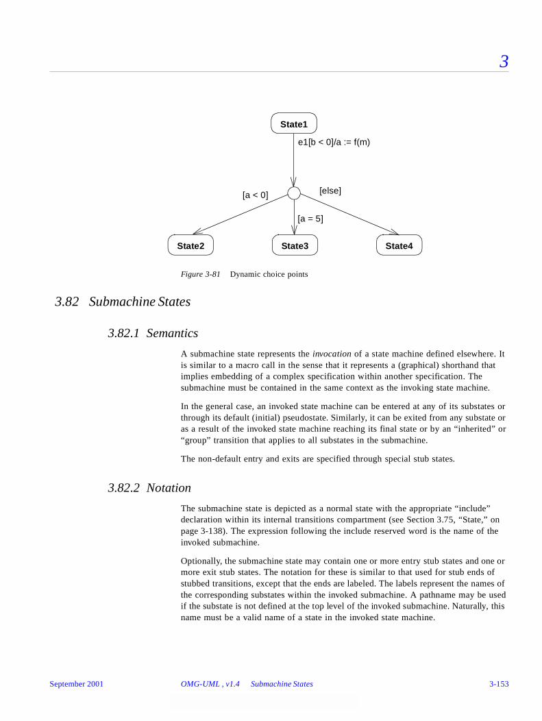
3
Figure 3-81 Dynamic choice points
3.82 Submachine States
3.82.1 Semantics
A submachine state represents the invocation of a state machine defined elsewhere. It is similar to a macro call in the sense that it represents a (graphical) shorthand that implies embedding of a complex specification within another specification. The submachine must be contained in the same context as the invoking state machine.
In the general case, an invoked state machine can be entered at any of its substates or through its default (initial) pseudostate. Similarly, it can be exited from any substate or as a result of the invoked state machine reaching its final state or by an “inherited” or “group” transition that applies to all substates in the submachine.
The non-default entry and exits are specified through special stub states.
3.82.2 Notation
The submachine state is depicted as a normal state with the appropriate “include” declaration within its internal transitions compartment (see Section 3.75, “State,” on page 3-138). The expression following the include reserved word is the name of the invoked submachine.
Optionally, the submachine state may contain one or more entry stub states and one or more exit stub states. The notation for these is similar to that used for stub ends of stubbed transitions, except that the ends are labeled. The labels represent the names of the corresponding substates within the invoked submachine. A pathname may be used if the substate is not defined at the top level of the invoked submachine. Naturally, this name must be a valid name of a state in the invoked state machine.
[a < 0]
State1
State2 State3 State4
e1[b < 0]/a := f(m)
[a = 5]
[else]
September 2001 OMG-UML , v1.4 Submachine States 3-153
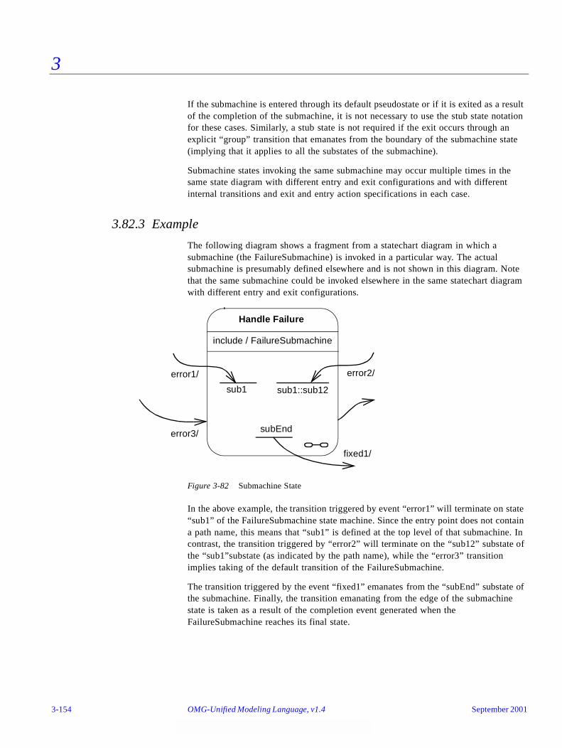
3
If the submachine is entered through its default pseudostate or if it is exited as a result of the completion of the submachine, it is not necessary to use the stub state notation for these cases. Similarly, a stub state is not required if the exit occurs through an explicit “group” transition that emanates from the boundary of the submachine state (implying that it applies to all the substates of the submachine).
Submachine states invoking the same submachine may occur multiple times in the same state diagram with different entry and exit configurations and with different internal transitions and exit and entry action specifications in each case.
3.82.3 Example
The following diagram shows a fragment from a statechart diagram in which a submachine (the FailureSubmachine) is invoked in a particular way. The actual submachine is presumably defined elsewhere and is not shown in this diagram. Note that the same submachine could be invoked elsewhere in the same statechart diagram with different entry and exit configurations.
Figure 3-82 Submachine State
In the above example, the transition triggered by event “error1” will terminate on state “sub1” of the FailureSubmachine state machine. Since the entry point does not contain a path name, this means that “sub1” is defined at the top level of that submachine. In contrast, the transition triggered by “error2” will terminate on the “sub12” substate of the “sub1”substate (as indicated by the path name), while the “error3” transition implies taking of the default transition of the FailureSubmachine.
The transition triggered by the event “fixed1” emanates from the “subEnd” substate of the submachine. Finally, the transition emanating from the edge of the submachine state is taken as a result of the completion event generated when the FailureSubmachine reaches its final state.
Handle Failure
include / FailureSubmachine
sub1 sub1::sub12
subEnd
error2/error1/
error3/
fixed1/
3-154 OMG-Unified Modeling Language, v1.4 September 2001
3
3.82.4 Mapping
A submachine state in a statechart diagram maps directly to a SubmachineState in the metamodel. The name following the “include” reserved action label represents the state machine indicated by the “submachine” attribute. Stub states map to the Stub State concept in the metamodel. The label on the diagram corresponds to the pathname represented by the “referenceState” attribute of the stub state.
3.83 Synch States
3.83.1 Semantics
A synch state is for synchronizing concurrent regions of a state machine. It is used in conjunction with forks and joins to insure that one region leaves a particular state or states before another region can enter a particular state or states. The firing of outgoing transitions from a synch state can be limited by specifying a bound on the difference between the number of times outgoing and incoming transitions have fired.
3.83.2 Notation
A synch state is shown as a small circle with the upper bound inside it. The bound is either a positive integer or an asterisk ('*') for unlimited. Synch states are drawn on the boundary between two regions when possible.
September 2001 OMG-UML , v1.4 Synch States 3-155
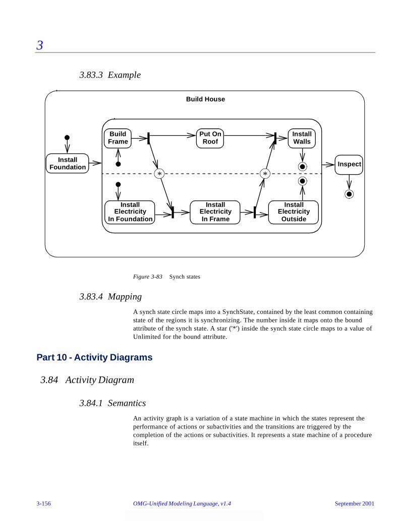
3
3.83.3 Example
Figure 3-83 Synch states
3.83.4 Mapping
A synch state circle maps into a SynchState, contained by the least common containing state of the regions it is synchronizing. The number inside it maps onto the bound attribute of the synch state. A star ('*') inside the synch state circle maps to a value of Unlimited for the bound attribute.
Part 10 - Activity Diagrams
3.84 Activity Diagram
3.84.1 Semantics
An activity graph is a variation of a state machine in which the states represent the performance of actions or subactivities and the transitions are triggered by the completion of the actions or subactivities. It represents a state machine of a procedure itself.
Build
InstallElectricity
Build House
InspectInstall
Foundation
Frame
In Foundation
InstallElectricityIn Frame
Put OnRoof
InstallElectricityOutside
InstallWalls
**
3-156 OMG-Unified Modeling Language, v1.4 September 2001

3
3.84.2 Notation
An activity diagram is a special case of a state diagram in which all (or at least most) of the states are action or subactivity states and in which all (or at least most) of the transitions are triggered by completion of the actions or subactivities in the source states. The entire activity diagram is attached (through the model) to a classifier, such as a use case, or to a package, or to the implementation of an operation. The purpose of this diagram is to focus on flows driven by internal processing (as opposed to external events). Use activity diagrams in situations where all or most of the events represent the completion of internally-generated actions (that is, procedural flow of control). Use ordinary state diagrams in situations where asynchronous events occur.
September 2001 OMG-UML , v1.4 Activity Diagram 3-157
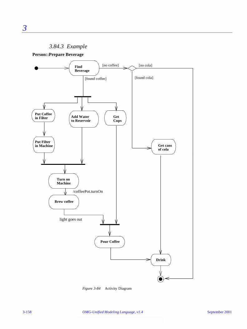
3
3.84.3 Example
Figure 3-84 Activity Diagram
GetCups
Put Coffeein Filter Add Water
to Reservoir
[found coffee]
[no coffee]FindBeverage
Get cansof cola
[no cola]
[found cola]
Put Filterin Machine
Turn onMachine
Person::Prepare Beverage
Brew coffee
Pour Coffee
Drink
/coffeePot.turnOn
light goes out
3-158 OMG-Unified Modeling Language, v1.4 September 2001
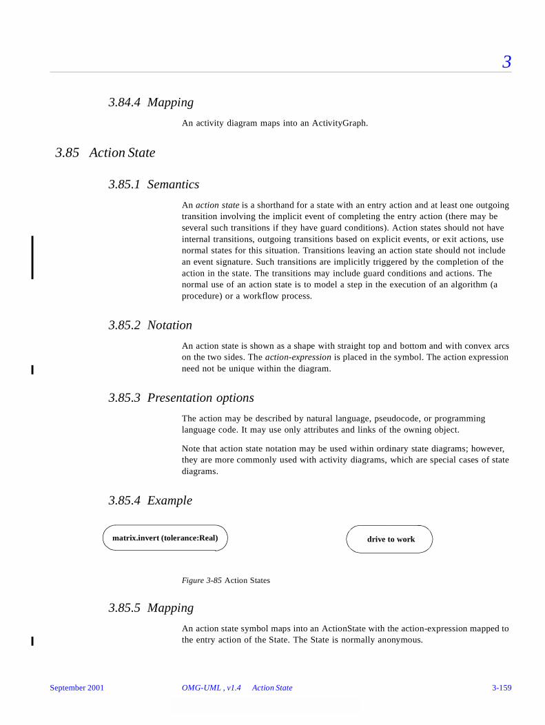
3
3.84.4 Mapping
An activity diagram maps into an ActivityGraph.
3.85 Action State
3.85.1 Semantics
An action state is a shorthand for a state with an entry action and at least one outgoing transition involving the implicit event of completing the entry action (there may be several such transitions if they have guard conditions). Action states should not have internal transitions, outgoing transitions based on explicit events, or exit actions, use normal states for this situation. Transitions leaving an action state should not include an event signature. Such transitions are implicitly triggered by the completion of the action in the state. The transitions may include guard conditions and actions. The normal use of an action state is to model a step in the execution of an algorithm (a procedure) or a workflow process.
3.85.2 Notation
An action state is shown as a shape with straight top and bottom and with convex arcs on the two sides. The action-expression is placed in the symbol. The action expression need not be unique within the diagram.
3.85.3 Presentation options
The action may be described by natural language, pseudocode, or programming language code. It may use only attributes and links of the owning object.
Note that action state notation may be used within ordinary state diagrams; however, they are more commonly used with activity diagrams, which are special cases of state diagrams.
3.85.4 Example
Figure 3-85 Action States
3.85.5 Mapping
An action state symbol maps into an ActionState with the action-expression mapped to the entry action of the State. The State is normally anonymous.
matrix.invert (tolerance:Real) drive to work
September 2001 OMG-UML , v1.4 Action State 3-159
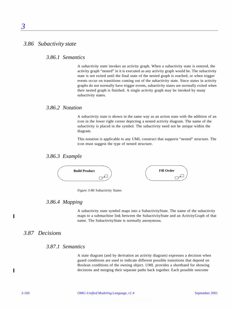
3
3.86 Subactivity state
3.86.1 Semantics
A subactivity state invokes an activity graph. When a subactivity state is entered, the activity graph “nested” in it is executed as any activity graph would be. The subactivity state is not exited until the final state of the nested graph is reached, or when trigger events occur on transitions coming out of the subactivity state. Since states in activity graphs do not normally have trigger events, subactivity states are normally exited when their nested graph is finished. A single activity graph may be invoked by many subactivity states.
3.86.2 Notation
A subactivity state is shown in the same way as an action state with the addition of an icon in the lower right corner depicting a nested activity diagram. The name of the subactivity is placed in the symbol. The subactivity need not be unique within the diagram.
This notation is applicable to any UML construct that supports “nested” structure. The icon must suggest the type of nested structure.
3.86.3 Example
Figure 3-86 Subactivity States
3.86.4 Mapping
A subactivity state symbol maps into a SubactivityState. The name of the subactivity maps to a submachine link between the SubactivityState and an ActivityGraph of that name. The SubactivityState is normally anonymous.
3.87 Decisions
3.87.1 Semantics
A state diagram (and by derivation an activity diagram) expresses a decision when guard conditions are used to indicate different possible transitions that depend on Boolean conditions of the owning object. UML provides a shorthand for showing decisions and merging their separate paths back together. Each possible outcome
Build Product Fill Order
3-160 OMG-Unified Modeling Language, v1.4 September 2001

3
should appear on one of the outgoing transitions. A predefined guard denoted “else” may be defined for at most one outgoing transition. This transition is enabled if all the guards labeling the other transitions are false.
3.87.2 Notation
A decision may be shown by labeling multiple output transitions of an action with different guard conditions.
The icon provided for a decision is the traditional diamond shape, with one incoming arrow and with two or more outgoing arrows, each labeled by a distinct guard condition with no event trigger.
The same icon can be used to merge decision branches back together, in which case it is called a merge. A merge has two or more incoming arrows and one outgoing arrow.
Note that a chain of decisions may be part of a complex transition, but only the first segment in such a chain may contain an event trigger label. All segments may have guard expressions. The transition coming from a merge may not have a trigger label or guard expressions.
3.87.3 Example
Figure 3-87 Decision and merge
3.87.4 Mapping
A decision symbol maps into a Pseudostate of kind junction. Each label on an outgoing arrow maps into a Guard on the corresponding Transition leaving the Pseudostate. A merge symbol also maps into a Pseudostate of kind junction.
Calculatetotal cost
[cost < $50] Chargecustomer’saccount
Getauthorization
[cost ≥ $50]
September 2001 OMG-UML , v1.4 Decisions 3-161
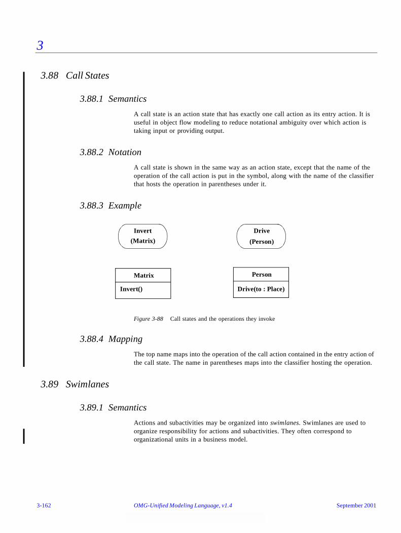
3
3.88 Call States
3.88.1 Semantics
A call state is an action state that has exactly one call action as its entry action. It is useful in object flow modeling to reduce notational ambiguity over which action is taking input or providing output.
3.88.2 Notation
A call state is shown in the same way as an action state, except that the name of the operation of the call action is put in the symbol, along with the name of the classifier that hosts the operation in parentheses under it.
3.88.3 Example
Figure 3-88 Call states and the operations they invoke
3.88.4 Mapping
The top name maps into the operation of the call action contained in the entry action of the call state. The name in parentheses maps into the classifier hosting the operation.
3.89 Swimlanes
3.89.1 Semantics
Actions and subactivities may be organized into swimlanes. Swimlanes are used to organize responsibility for actions and subactivities. They often correspond to organizational units in a business model.
Invert
(Matrix)
Drive
(Person)
Matrix
Invert()
Person
Drive(to : Place)
3-162 OMG-Unified Modeling Language, v1.4 September 2001
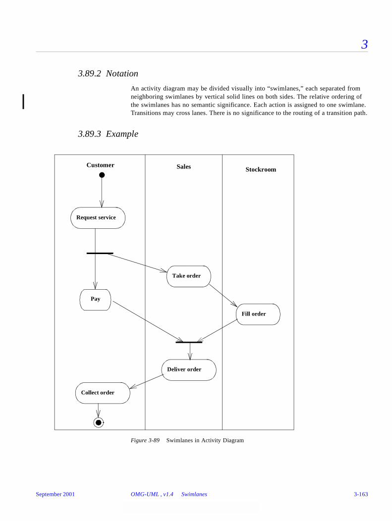
3
3.89.2 Notation
An activity diagram may be divided visually into “swimlanes,” each separated from neighboring swimlanes by vertical solid lines on both sides. The relative ordering of the swimlanes has no semantic significance. Each action is assigned to one swimlane. Transitions may cross lanes. There is no significance to the routing of a transition path.
3.89.3 Example
Figure 3-89 Swimlanes in Activity Diagram
Request service
Take order
Fill order
Collect order
Customer Sales Stockroom
Pay
Deliver order
September 2001 OMG-UML , v1.4 Swimlanes 3-163
3
3.89.4 Mapping
A swimlane maps into a Partition of the States in the ActivityGraph. A state symbol in a swimlane causes the corresponding State to belong to the corresponding Partition.
3.90 Action-Object Flow Relationships
3.90.1 Semantics
Actions operate by and on objects. These objects either have primary responsibility for initiating an action, or are used or determined by the action. Actions usually specify calls sent between the object owning the activity graph, which initiates actions, and the objects that are the targets of the actions.
3.90.2 Notation
3.90.2.1 Object responsible for an action
In sequence diagrams, the object responsible for performing an action is shown by drawing a lifeline and placing actions on lifelines (see Section 3.60, “Sequence Diagram,” on page 3-102). Activity diagrams do not show the lifeline, but each action specifies which object performs its operation. These objects may also be related to the swimlane in some way. The actions within a swimlane can all be handled by the same object or by multiple objects.
3.90.2.2 Object flow
Objects that are input to or output from an action may be shown as object symbols. A dashed arrow is drawn from an action state to an output object, and a dashed arrow is drawn from an input object to an action state. The same object may be (and usually is) the output of one action and the input of one or more subsequent actions.
The control flow (solid) arrows must be omitted when the object flow (dashed) arrows supply a redundant constraint. In other words, when a state produces an output that is input to a subsequent state, that object flow relationship implies a control constraint.
3.90.2.3 Object in state
Frequently the same object is manipulated by a number of successive actions or subactivities. It is possible to show one object with arrows to and from all of the relevant actions and subactivities, but for greater clarity, the object may be displayed multiple times on a diagram. Each appearance denotes a different point during the object’s life. To distinguish the various appearances of the same object, the state of the object at each point may be placed in brackets and appended to the name of the object (for example, PurchaseOrder[approved]). This notation may also be used in collaboration and sequence diagrams.
3-164 OMG-Unified Modeling Language, v1.4 September 2001

3
3.90.3 Example
Figure 3-90 Actions and Object Flow
3.90.4 Mapping
An object flow symbol maps into an ObjectFlowState whose incoming and outgoing Transitions correspond to the incoming and outgoing arrows. The Transitions have no attachments. The classifier name and (optional) state name of the object flow symbol map into a Class or a ClassifierInState corresponding to the name(s). Solid and dashed arrows both map to transitions.
Request service
Take order
Fill order
Collect order
Customer Sales Stockroom
Pay
Deliver order
Order[entered]
Order[filled]
Order[delivered]
Order[placed]
September 2001 OMG-UML , v1.4 Action-Object Flow Relationships 3-165
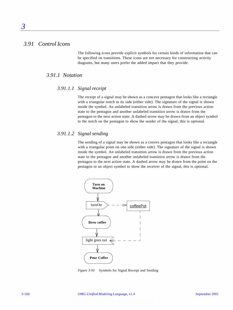
3
3.91 Control Icons
The following icons provide explicit symbols for certain kinds of information that can be specified on transitions. These icons are not necessary for constructing activity diagrams, but many users prefer the added impact that they provide.
3.91.1 Notation
3.91.1.1 Signal receipt
The receipt of a signal may be shown as a concave pentagon that looks like a rectangle with a triangular notch in its side (either side). The signature of the signal is shown inside the symbol. An unlabeled transition arrow is drawn from the previous action state to the pentagon and another unlabeled transition arrow is drawn from the pentagon to the next action state. A dashed arrow may be drawn from an object symbol to the notch on the pentagon to show the sender of the signal; this is optional.
3.91.1.2 Signal sending
The sending of a signal may be shown as a convex pentagon that looks like a rectangle with a triangular point on one side (either side). The signature of the signal is shown inside the symbol. An unlabeled transition arrow is drawn from the previous action state to the pentagon and another unlabeled transition arrow is drawn from the pentagon to the next action state. A dashed arrow may be drawn from the point on the pentagon to an object symbol to show the receiver of the signal, this is optional.
Figure 3-91 Symbols for Signal Receipt and Sending
Turn onMachine
Brew coffee
Pour Coffee
turnOn
light goes out
coffeePot
3-166 OMG-Unified Modeling Language, v1.4 September 2001

3
3.91.1.3 Deferred events
A frequent situation is when an event that occurs must be “deferred” for later use while some other action or subactivity is underway. (Normally an event that is not handled immediately is lost.) This may be thought of as having an internal transition that handles the event and places it on an internal queue until it is needed or until it is discarded. Each state specifies a set of events that are deferred if they occur during the state and are not used to trigger a transition. If an event is not included in the set of deferrable events for a state, and it does not trigger a transition, then it is discarded from the queue even if it has already occurred. If a transition depends on an event, the transition fires immediately if the event is already on the internal queue. If several transitions are possible, the leading event in the queue takes precedence.
A deferrable event is shown by listing it within the state followed by a slash and the special operation defer. If the event occurs, it is saved and it recurs when the object transitions to another state, where it may be deferred again. When the object reaches a state in which the event is not deferred, it must be accepted or lost. The indication may be placed on a composite state or its equivalents, submachine and subactivity states, in which case it remains deferrable throughout the composite state. A contained transition may still be triggered by a deferrable event, whereupon it is removed from the queue.
It is not necessary to defer events on action states, because these states are not interruptible for event processing. In this case, both deferred and undeferred events that occur during the state are deferred until the state is completed. This means that the timing of the transition will be the same regardless of the relative order of the event and the state completion, and regardless of whether events are deferred.
September 2001 OMG-UML , v1.4 Control Icons 3-167
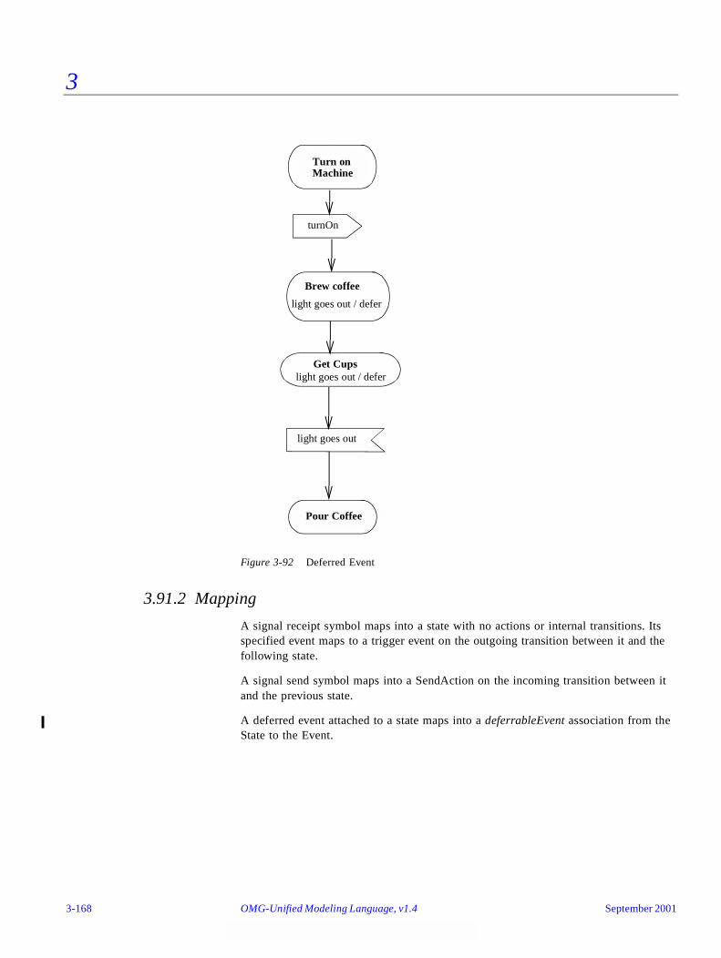
3
Figure 3-92 Deferred Event
3.91.2 Mapping
A signal receipt symbol maps into a state with no actions or internal transitions. Its specified event maps to a trigger event on the outgoing transition between it and the following state.
A signal send symbol maps into a SendAction on the incoming transition between it and the previous state.
A deferred event attached to a state maps into a deferrableEvent association from the State to the Event.
Turn onMachine
Brew coffee
Pour Coffee
turnOn
light goes out / defer
Get Cups
light goes out
light goes out / defer
3-168 OMG-Unified Modeling Language, v1.4 September 2001
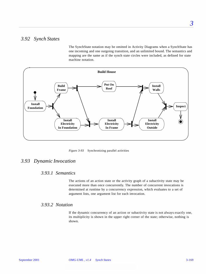
3
3.92 Synch States
The SynchState notation may be omitted in Activity Diagrams when a SynchState has one incoming and one outgoing transition, and an unlimited bound. The semantics and mapping are the same as if the synch state circles were included, as defined for state machine notation.
Figure 3-93 Synchronizing parallel activities
3.93 Dynamic Invocation
3.93.1 Semantics
The actions of an action state or the activity graph of a subactivity state may be executed more than once concurrently. The number of concurrent invocations is determined at runtime by a concurrency expression, which evaluates to a set of argument lists, one argument list for each invocation.
3.93.2 Notation
If the dynamic concurrency of an action or subactivity state is not always exactly one, its multiplicity is shown in the upper right corner of the state; otherwise, nothing is shown.
Build
InstallElectricity
Build House
InspectInstall
Foundation
Frame
In Foundation
InstallElectricityIn Frame
Put OnRoof
InstallElectricity
Outside
InstallWalls
September 2001 OMG-UML , v1.4 Synch States 3-169

3
3.93.3 Mapping
A multiplicity string in the upper right corner of an action or subactivity state maps to the same value in the dynamicMultiplicity attribute of the state. The presence of a multiplicity string also maps to a value of true for the isDynamic attribute of the state. If no multiplicity is present, the value of the isDynamic attribute is false.
3.94 Conditional Forks
In Activity Diagrams, transitions outgoing from forks may have guards. This means the region initiated by a fork transition might not start, and therefore is not required to complete at the corresponding join. The usual notation and mapping for guards may be used on the transition outgoing from a fork.
Part 11 - Implementation DiagramsImplementation diagrams show aspects of physical implementation, including the structure of components and the run-time deployment system. They come in two forms: 1) component diagrams show the structure of components, including the classifiers that specify them and the artifacts that implement them; and 2) deployment diagrams show the structure of the nodes on which the components are deployed. These diagrams can also be applied in a broader way to business modeling where the components represent business procedures and artifacts, and the deployment nodes represent the organization units and resources (human and otherwise) of the business.
3.95 Component Diagram
3.95.1 Semantics
A component diagram shows the dependencies among software components, including the classifiers that specify them (for example, implementation classes) and the artifacts that implement them; such as, source code files, binary code files, executable files, scripts.
A component diagram has only a type form, not an instance form. To show component instances, use a deployment diagram (possibly a degenerate one without nodes).
3.95.2 Notation
A component diagram is a graph of components connected by dependency relationships. Components may also be connected to components by physical containment representing composition relationships.
3-170 OMG-Unified Modeling Language, v1.4 September 2001
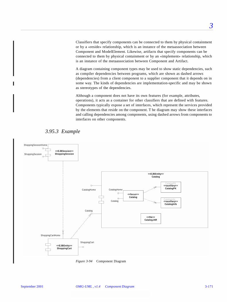
3
Classifiers that specify components can be connected to them by physical containment or by a «reside» relationship, which is an instance of the metaassociation between Component and ModelElement. Likewise, artifacts that specify components can be connected to them by physical containment or by an «implement» relationship, which is an instance of the metaassociation between Component and Artifact.
A diagram containing component types may be used to show static dependencies, such as compiler dependencies between programs, which are shown as dashed arrows (dependencies) from a client component to a supplier component that it depends on in some way. The kinds of dependencies are implementation-specific and may be shown as stereotypes of the dependencies.
Although a component does not have its own features (for example, attributes, operations), it acts as a container for other classifiers that are defined with features. Components typically expose a set of interfaces, which represent the services provided by the elements that reside on the component. T he diagram may show these interfaces and calling dependencies among components, using dashed arrows from components to interfaces on other components.
3.95.3 Example
Figure 3-94 Component Diagram
<<EJBEntity>>Catalog
CatalogHom e
Catalog
CatalogPK
<<EJBSession>>ShoppingSession
ShoppingSessionHom e
ShoppingSession
CatalogInfo
<<file>>CatalogJAR
<<focus>>Catalog
<<auxiliary>>CatalogPK
<<auxiliary>>CatalogInfo
CatalogHom e
Catalog
<<EJBEntity>>ShoppingCart
ShoppingCartHome
ShoppingCart
September 2001 OMG-UML , v1.4 Component Diagram 3-171

3
Figure 3-95 Component Diagram Showing Relationships with Classifiers and Artifacts
3.95.4 Mapping
A component diagram maps to a static model whose elements include Components. The physical containment of a Classifier by a Component represents a «reside» relationship, which is an instance of the metaassociation between Component and ModelElement. The physical containment of an Artifact by a Component represents an «implement» relationship, which is an instance of the metaassociation between Component and Artifact.
3.96 Deployment Diagram
3.96.1 Semantics
Deployment diagrams show the configuration of run-time processing elements and the software components, processes, and objects that execute on them. Software component instances represent run-time manifestations of software code units. Components that do not exist as run-time entities (because they have been compiled away) do not appear on these diagrams, they should be shown on component diagrams.
<<ejbEntity>>Catalog
<<auxiliary>>CatalogInfo
<<focus>>Catalog
< <res id e> > < <res id e> >
<<auxiliary>>CatalogPK
< <res id e> >
<<file>>CatalogJAR
< <im p lem ent> >
3-172 OMG-Unified Modeling Language, v1.4 September 2001

3
For business modeling, the run-time processing elements include workers and organizational units, and the software components include procedures and documents used by the workers and organizational units.
3.96.2 Notation
A deployment diagram is a graph of nodes connected by communication associations. Nodes may contain component instances. This indicates that the component runs or executes on the node. Components may contain instances of classifiers, which indicates that the instance resides on the component. Components are connected to other components by dashed-arrow dependencies (possibly through interfaces). This indicates that one component uses the services of another component. A stereotype may be used to indicate the precise dependency, if needed.
The deployment type diagram may also be used to show which components may reside on which nodes, by using dashed arrows with the stereotype «deploy» from the component symbol to the node symbol or by graphically nesting the component symbol within the node symbol.
Migration of component instances from node instance to node instance or objects from component instance to component instance may be shown using the «become» stereotype of the dependency relationship. In this case the component instance or object is resident on its node instance or component instance only part of the entire time.
Note that a process is just a special kind of object (see Section 3.71, “Active object,” on page 3-129).
September 2001 OMG-UML , v1.4 Deployment Diagram 3-173

3
3.96.3 Example
Figure 3-96 Deployment Diagram
3.96.4 Mapping
A deployment diagram maps to a static model whose elements include Nodes. It is not particularly distinguished in the model.
3.97 Node
3.97.1 Semantics
A node is a physical object that represents a processing resource, generally, having at least a memory and often processing capability as well. Nodes include computing devices but also human resources or mechanical processing resources. Nodes may be represented as types and as instances. Run time computational instances, both objects and component instances, may reside on node instances.
3.97.2 Notation
A node is shown as a figure that looks like a 3-dimensional view of a cube. A node type has a type name:
:DBServer
videoStoreServer:AppServer
<<C ontainer>> Vi deo StoreApplication
:Client
<<b ro w ser>>:OpenS ourceB ro w ser
<<S ess ion>>S hopp ingSess ion
<<Focus>>S hopp ingSess ion
<<E ntity>>C atalog
<<Focus>>C atalog
<<E ntity>>S hopp ingCart
<<Focus>>S hopp ingCart
<<database>>:VideoS toreD B
3-174 OMG-Unified Modeling Language, v1.4 September 2001
3
node-type
A node instance has a name and a type name. The node may have an underlined name string in it or below it. The name string has the syntax:
name ‘:’ node-type
The name is the name of the individual node (if any). The node-type says what kind of a node it is. Either or both elements are optional; if the node-type is omitted, then so is the colon.
Dashed arrows with the keyword «deploy» show the capability of a node type to support a component type. Alternatively, this may be shown by nesting component symbols inside the node symbol.
Component instances and objects may be contained within node instance symbols. This indicates that the items reside on the node instances.
Nodes may be connected by associations to other nodes. An association between nodes indicates a communication path between the nodes. The association may have a stereotype to indicate the nature of the communication path (for example, the kind of channel or network).
3.97.3 Example
This example shows two nodes containing components, where a «become» flow shows the backupBroker migrating from the backupServer to the primaryServer while the other components remain in place.
September 2001 OMG-UML , v1.4 Node 3-175
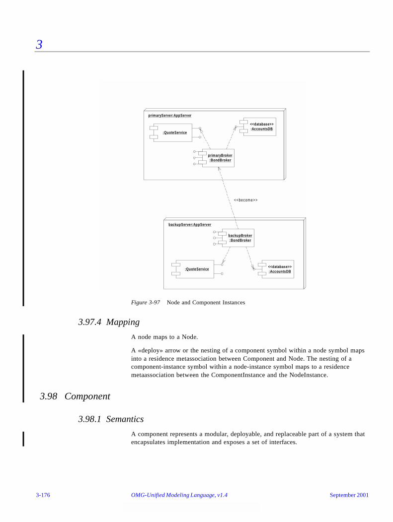
3
Figure 3-97 Node and Component Instances
3.97.4 Mapping
A node maps to a Node.
A «deploy» arrow or the nesting of a component symbol within a node symbol maps into a residence metassociation between Component and Node. The nesting of a component-instance symbol within a node-instance symbol maps to a residence metaassociation between the ComponentInstance and the NodeInstance.
3.98 Component
3.98.1 Semantics
A component represents a modular, deployable, and replaceable part of a system that encapsulates implementation and exposes a set of interfaces.
backupServer:AppServer
backupBroker:BondBroker
:QuoteService<<database>>:AccountsDB
primaryServer:AppServer
primaryBroker:BondBroker
:QuoteService
<<database>>:AccountsDB
<<becom e>>
3-176 OMG-Unified Modeling Language, v1.4 September 2001
3
A component is typically specified by one or more classifiers that reside on the component. A subset of these classifiers explicitly define the component’s external interfaces. A component conforms to the interfaces that it exposes, where the interfaces represent services provided by elements that reside on the component. A component may be implemented by one or more artifacts, such as binary, executable, or script files. A component may be deployed on a node.
3.98.2 Notation
A component is shown as a rectangle with two small rectangles protruding from its side. A component type has a type name:
component-type
A component instance has a name and a type. The name of the component and its type may be shown as an underlined string either within the component symbol or above or below it, with the syntax:
component-name ‘:’ component-type
Either or both elements are optional. If the component-type is omitted, then so is the colon.
Objects that reside on a component instance are shown as nested inside the component instance symbol. By analogy, classes that are implemented by a component may be shown as nested within it; this indicates residence and not ownership.
Elements that reside on a component are shown nested inside the component symbol. The visibility of a resident element to other components may be shown using the same notation as for the visibility of the contents of a package (prepending a visibility symbol to the name of the package). The meaning of the visibility depends on the nature of the component. For a source-language component (such as program text), it would control the accessibility of source-language constructs. For a run-time code component (such as executable code), it would control the ability of code in other components to call or otherwise access code in the component.
3.98.3 Example
The example shows a component with interfaces and also a component that contains objects at run time.
September 2001 OMG-UML , v1.4 Component 3-177
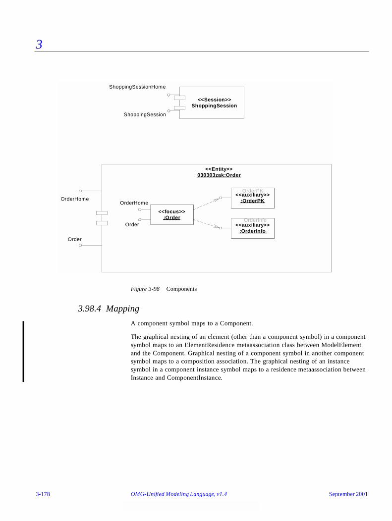
3
Figure 3-98 Components
3.98.4 Mapping
A component symbol maps to a Component.
The graphical nesting of an element (other than a component symbol) in a component symbol maps to an ElementResidence metaassociation class between ModelElement and the Component. Graphical nesting of a component symbol in another component symbol maps to a composition association. The graphical nesting of an instance symbol in a component instance symbol maps to a residence metaassociation between Instance and ComponentInstance.
<<Entity>>030303zak:Order
OrderHome
Order
OrderPK
<<Session>>ShoppingSession
ShoppingSessionHome
ShoppingSession
OrderInfo
<<focus>>:Order
<<auxiliary>>:OrderPK
<<auxiliary>>:OrderInfo
OrderHome
Order
3-178 OMG-Unified Modeling Language, v1.4 September 2001

UML Example Profiles 4
Contents
This chapter contains the following topics.
Part 1 - UML Profile for Software Development Processes
4.1 Introduction
The UML Profile for Software Development Processes is an example profile that is based on the Unified Process for software engineering. The profile is defined using the extensibility mechanisms of UML, which allow modelers to customize UML for specific domains, such as software development processes.
Topic Page
“Part 1 - UML Profile for Software Development Processes”
“Introduction” 4-1
“Summary of Profile” 4-2
“Stereotypes and Notation” 4-2
“Well-Formedness Rules” 4-9
“Example 2 - UML Profile for Business Modeling”
“Introduction” 4-9
“Summary of Profile” 4-10
“Stereotypes and Notation” 4-10
“Well-Formedness Rules” 4-16
September 2001 OMG-Unified Modeling Language, v1.4 4-1

4
Note that this profile is not a complete definition of the Unified Process or how to apply it, but rather an example that shows how some of the profile terminology and notation is used. This example is defined only through stereotypes and constraints; profiles also commonly include tagged values.
4.2 Summary of Profile
The stereotypes that are defined by this profile are summarized in Table 4-1.
4.3 Stereotypes and Notation
A system modeled by the Unified Process consists of several different, but related models. These models are characterized by the lifecycle stage that they represent, and each model makes use of one specific stereotype. Many of the stereotypes are used particularly to give the ability to structure and categorize models and systems during different stages of the development process.
Table 4-1 Stereotype Summary
Name Base Class
UseCaseModel Model
AnalysisModel Model
DesignModel Model
ImplementationModel Model
UseCaseSystem Package
AnalysisSystem Package
DesignSystem Subsystem
ImplementationSystem Subsystem
AnalysisPackage Package
DesignSubsystem Subsystem
ImplementationSubsystem Subsystem
UseCasePackage Package
AnalysisServicePackage Package
DesignServiceSubsystem Subsystem
Boundary Class
Entity Class
Control Class
Communicate Association
Subscribe Association
4-2 OMG-Unified Modeling Language, v1.4 September 2001

4
In addition, there are stereotypes describing different kinds of commonly occurring analysis classes (such as boundary, entity, and control) and their relationships, whereas design classes are by default not stereotyped in the Unified Process.
4.3.1 Use Case Stereotypes
4.3.1.1 UseCaseModel
The notation used for a UseCaseModel is a package stereotyped as «useCaseModel». Though superfluous, it is optionally possible to in addition use the model icon in the upper right corner of the package symbol.
The explicit modeling of the stereotype is shown in Figure 4-1.
Figure 4-1 Explicit Modeling of a Stereotype
4.3.1.2 UseCaseSystem
The notation used for a UseCaseSystem is a package stereotyped as «useCaseSystem».
Stereotype Base Class Parent Description Constraints
UseCaseModel«useCaseModel»
Model NA A use case model specifies the services a system provides to its users; that is, the different ways of using the system, and whose top-level package is a use case system.
None.
Stereotype Base Class Parent Description Constraints
UseCaseSystem«useCaseSystem»
Package NA A use case system is a top-level package that may contain use case packages, use cases, and relationships.
None.
UseCaseModel<<stereotype>>
Model<<metaclass>>
<<stereotype>>
September 2001 OMG-UML , v1.4 Stereotypes and Notation 4-3
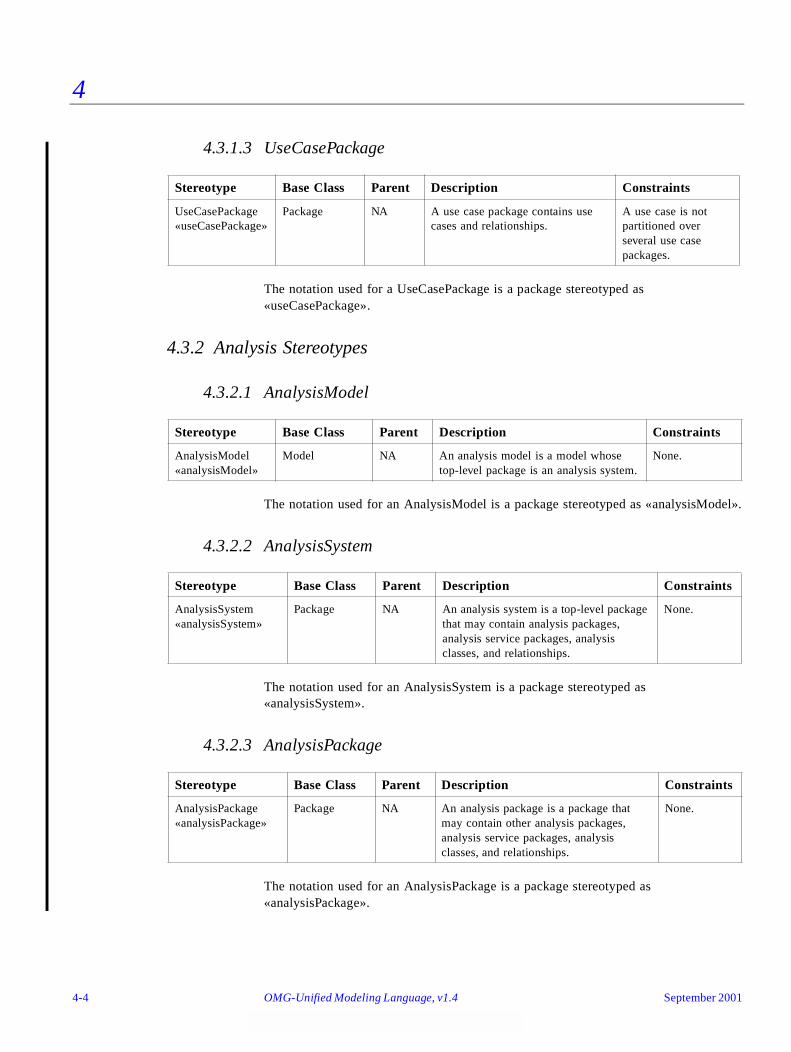
4
4.3.1.3 UseCasePackage
The notation used for a UseCasePackage is a package stereotyped as «useCasePackage».
4.3.2 Analysis Stereotypes
4.3.2.1 AnalysisModel
The notation used for an AnalysisModel is a package stereotyped as «analysisModel».
4.3.2.2 AnalysisSystem
The notation used for an AnalysisSystem is a package stereotyped as «analysisSystem».
4.3.2.3 AnalysisPackage
The notation used for an AnalysisPackage is a package stereotyped as «analysisPackage».
Stereotype Base Class Parent Description Constraints
UseCasePackage«useCasePackage»
Package NA A use case package contains use cases and relationships.
A use case is not partitioned over several use case packages.
Stereotype Base Class Parent Description Constraints
AnalysisModel«analysisModel»
Model NA An analysis model is a model whose top-level package is an analysis system.
None.
Stereotype Base Class Parent Description Constraints
AnalysisSystem«analysisSystem»
Package NA An analysis system is a top-level package that may contain analysis packages, analysis service packages, analysis classes, and relationships.
None.
Stereotype Base Class Parent Description Constraints
AnalysisPackage«analysisPackage»
Package NA An analysis package is a package that may contain other analysis packages, analysis service packages, analysis classes, and relationships.
None.
4-4 OMG-Unified Modeling Language, v1.4 September 2001
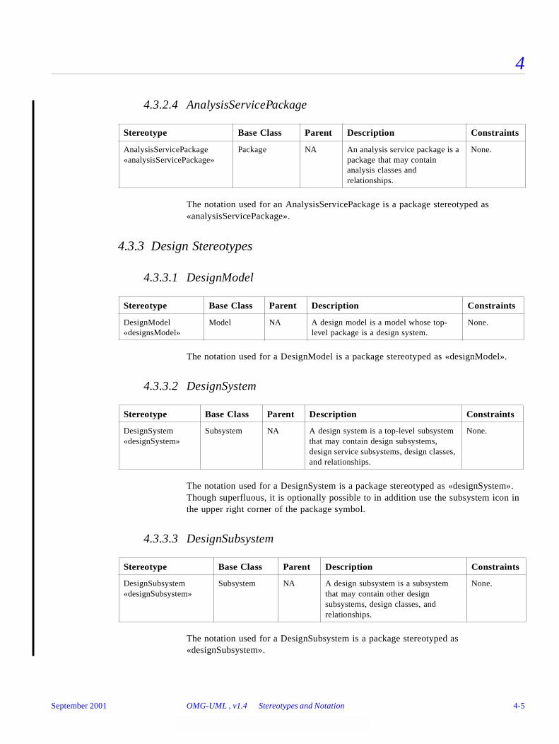
4
4.3.2.4 AnalysisServicePackage
The notation used for an AnalysisServicePackage is a package stereotyped as «analysisServicePackage».
4.3.3 Design Stereotypes
4.3.3.1 DesignModel
The notation used for a DesignModel is a package stereotyped as «designModel».
4.3.3.2 DesignSystem
The notation used for a DesignSystem is a package stereotyped as «designSystem». Though superfluous, it is optionally possible to in addition use the subsystem icon in the upper right corner of the package symbol.
4.3.3.3 DesignSubsystem
The notation used for a DesignSubsystem is a package stereotyped as «designSubsystem».
Stereotype Base Class Parent Description Constraints
AnalysisServicePackage«analysisServicePackage»
Package NA An analysis service package is a package that may contain analysis classes and relationships.
None.
Stereotype Base Class Parent Description Constraints
DesignModel«designsModel»
Model NA A design model is a model whose top-level package is a design system.
None.
Stereotype Base Class Parent Description Constraints
DesignSystem«designSystem»
Subsystem NA A design system is a top-level subsystem that may contain design subsystems, design service subsystems, design classes, and relationships.
None.
Stereotype Base Class Parent Description Constraints
DesignSubsystem«designSubsystem»
Subsystem NA A design subsystem is a subsystem that may contain other design subsystems, design classes, and relationships.
None.
September 2001 OMG-UML , v1.4 Stereotypes and Notation 4-5
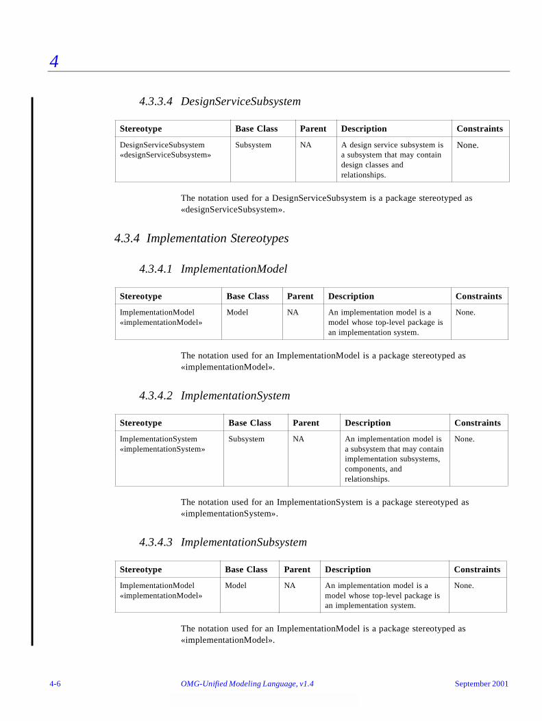
4
4.3.3.4 DesignServiceSubsystem
The notation used for a DesignServiceSubsystem is a package stereotyped as «designServiceSubsystem».
4.3.4 Implementation Stereotypes
4.3.4.1 ImplementationModel
The notation used for an ImplementationModel is a package stereotyped as «implementationModel».
4.3.4.2 ImplementationSystem
The notation used for an ImplementationSystem is a package stereotyped as «implementationSystem».
4.3.4.3 ImplementationSubsystem
The notation used for an ImplementationModel is a package stereotyped as «implementationModel».
Stereotype Base Class Parent Description Constraints
DesignServiceSubsystem«designServiceSubsystem»
Subsystem NA A design service subsystem is a subsystem that may contain design classes and relationships.
None.
Stereotype Base Class Parent Description Constraints
ImplementationModel«implementationModel»
Model NA An implementation model is a model whose top-level package is an implementation system.
None.
Stereotype Base Class Parent Description Constraints
ImplementationSystem«implementationSystem»
Subsystem NA An implementation model is a subsystem that may contain implementation subsystems, components, and relationships.
None.
Stereotype Base Class Parent Description Constraints
ImplementationModel«implementationModel»
Model NA An implementation model is a model whose top-level package is an implementation system.
None.
4-6 OMG-Unified Modeling Language, v1.4 September 2001

4
4.3.5 Class Stereotypes
4.3.5.1 Entity
The notation for Entity is shown below.
4.3.5.2 Control
The notation for Control is shown below.
4.3.5.3 Boundary
The notation for Boundary is shown below.
4.3.5.4 Notation
The notation given as part of the UML specification for stereotyped classes can be used for entity, control, and boundary, but it is also possible to substitute that notation with the icons shown below.
Stereotype Base Class Parent Description Constraints
Entity«entity»
Class NA An entity is a passive class; that is, its objects do not initiate interactions on their own. An entity object may participate in many different use case realizations and usually outlives any single interaction.
None.
Stereotype Base Class Parent Description Constraints
Control«control»
Class NA A control is a class whose objects manage interactions between collections of objects. A control class usually has behavior that is specific for one use case, and a control object usually does not outlive the use case realizations in which it participates.
None.
Stereotype Base Class Parent Description Constraints
Boundary«boundary»
Class NA A boundary is a class that lies on the periphery of a system, but within it. It interacts with actors outside the system as well as with entity, control, and other boundary classes within the system.
None.
September 2001 OMG-UML , v1.4 Stereotypes and Notation 4-7
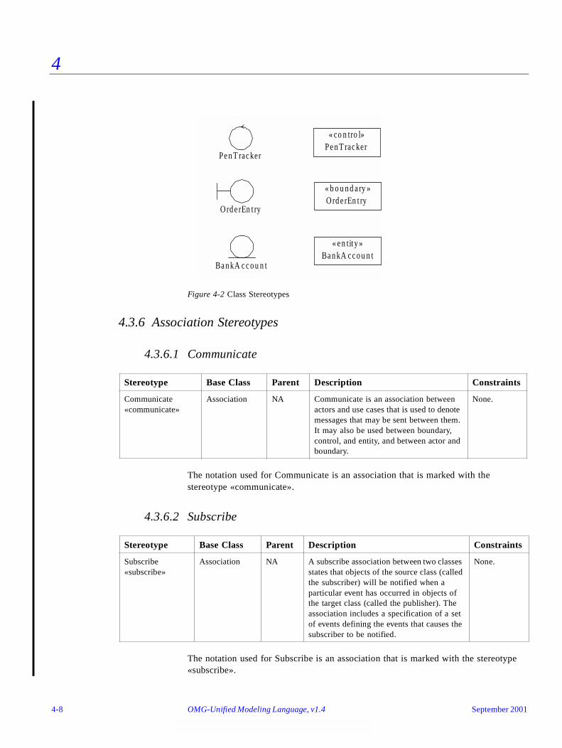
4
Figure 4-2 Class Stereotypes
4.3.6 Association Stereotypes
4.3.6.1 Communicate
The notation used for Communicate is an association that is marked with the stereotype «communicate».
4.3.6.2 Subscribe
The notation used for Subscribe is an association that is marked with the stereotype «subscribe».
Stereotype Base Class Parent Description Constraints
Communicate«communicate»
Association NA Communicate is an association between actors and use cases that is used to denote messages that may be sent between them. It may also be used between boundary, control, and entity, and between actor and boundary.
None.
Stereotype Base Class Parent Description Constraints
Subscribe«subscribe»
Association NA A subscribe association between two classes states that objects of the source class (called the subscriber) will be notified when a particular event has occurred in objects of the target class (called the publisher). The association includes a specification of a set of events defining the events that causes the subscriber to be notified.
None.
Pe n T rac kerPe n T rac ker
« co n tro l»
O rd e rEn t ryO rd e rEn t ry« b o u n d a ry »
Ba n kA c c o u n tBa n kA c c o u n t
« e n tity »
4-8 OMG-Unified Modeling Language, v1.4 September 2001
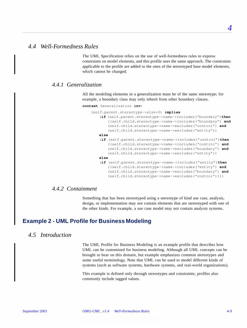
4
4.4 Well-Formedness Rules
The UML Specification relies on the use of well-formedness rules to express constraints on model elements, and this profile uses the same approach. The constraints applicable to the profile are added to the ones of the stereotyped base model elements, which cannot be changed.
4.4.1 Generalization
All the modeling elements in a generalization must be of the same stereotype; for example, a boundary class may only inherit from other boundary classes.
context Generalization inv:
(self.parent.stereotype->size>0) implies (if (self.parent.stereotype->name->includes(“boundary”)then
((self.child.stereotype->name->includes(“boundary”) and(self.child.stereotype->name->excludes(“control”) and (self.child.stereotype->name->excludes(“entity”))
else(if (self.parent.stereotype->name->includes(“control”)then
((self.child.stereotype->name->includes(“control”) and(self.child.stereotype->name->excludes(“boundary”) and (self.child.stereotype->name->excludes(“entity”))
else(if (self.parent.stereotype->name->includes(“entity”)then
((self.child.stereotype->name->includes(“entity”) and(self.child.stereotype->name->excludes(“boundary”) and (self.child.stereotype->name->excludes(“control”))))
4.4.2 Containment
Something that has been stereotyped using a stereotype of kind use case, analysis, design, or implementation may not contain elements that are stereotyped with one of the other kinds. For example, a use case model may not contain analysis systems.
Example 2 - UML Profile for Business Modeling
4.5 Introduction
The UML Profile for Business Modeling is an example profile that describes how UML can be customized for business modeling. Although all UML concepts can be brought to bear on this domain, but example emphasizes common stereotypes and some useful terminology. Note that UML can be used to model different kinds of systems (such as software systems, hardware systems, and real-world organizations).
This example is defined only through stereotypes and constraints; profiles also commonly include tagged values.
September 2001 OMG-UML , v1.4 Well-Formedness Rules 4-9
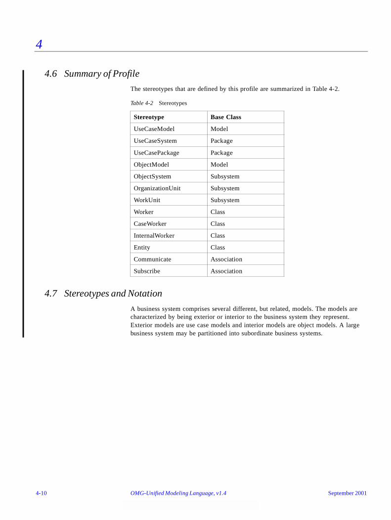
4
4.6 Summary of Profile
The stereotypes that are defined by this profile are summarized in Table 4-2.
4.7 Stereotypes and Notation
A business system comprises several different, but related, models. The models are characterized by being exterior or interior to the business system they represent. Exterior models are use case models and interior models are object models. A large business system may be partitioned into subordinate business systems.
Table 4-2 Stereotypes
Stereotype Base Class
UseCaseModel Model
UseCaseSystem Package
UseCasePackage Package
ObjectModel Model
ObjectSystem Subsystem
OrganizationUnit Subsystem
WorkUnit Subsystem
Worker Class
CaseWorker Class
InternalWorker Class
Entity Class
Communicate Association
Subscribe Association
4-10 OMG-Unified Modeling Language, v1.4 September 2001
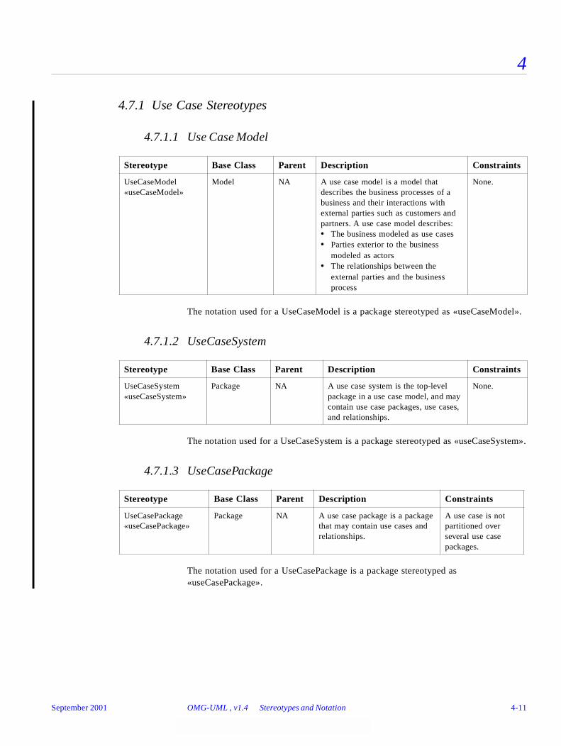
4
4.7.1 Use Case Stereotypes
4.7.1.1 Use Case Model
The notation used for a UseCaseModel is a package stereotyped as «useCaseModel».
4.7.1.2 UseCaseSystem
The notation used for a UseCaseSystem is a package stereotyped as «useCaseSystem».
4.7.1.3 UseCasePackage
The notation used for a UseCasePackage is a package stereotyped as «useCasePackage».
Stereotype Base Class Parent Description Constraints
UseCaseModel«useCaseModel»
Model NA A use case model is a model that describes the business processes of a business and their interactions with external parties such as customers and partners. A use case model describes:• The business modeled as use cases• Parties exterior to the business
modeled as actors• The relationships between the
external parties and the business process
None.
Stereotype Base Class Parent Description Constraints
UseCaseSystem«useCaseSystem»
Package NA A use case system is the top-level package in a use case model, and may contain use case packages, use cases, and relationships.
None.
Stereotype Base Class Parent Description Constraints
UseCasePackage«useCasePackage»
Package NA A use case package is a package that may contain use cases and relationships.
A use case is not partitioned over several use case packages.
September 2001 OMG-UML , v1.4 Stereotypes and Notation 4-11
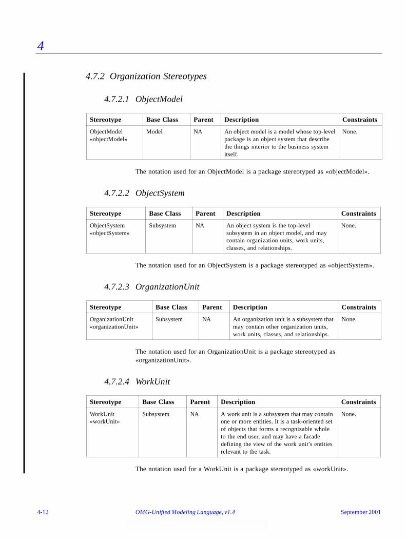
4
4.7.2 Organization Stereotypes
4.7.2.1 ObjectModel
The notation used for an ObjectModel is a package stereotyped as «objectModel».
4.7.2.2 ObjectSystem
The notation used for an ObjectSystem is a package stereotyped as «objectSystem».
4.7.2.3 OrganizationUnit
The notation used for an OrganizationUnit is a package stereotyped as «organizationUnit».
4.7.2.4 WorkUnit
The notation used for a WorkUnit is a package stereotyped as «workUnit».
Stereotype Base Class Parent Description Constraints
ObjectModel«objectModel»
Model NA An object model is a model whose top-level package is an object system that describe the things interior to the business system itself.
None.
Stereotype Base Class Parent Description Constraints
ObjectSystem«objectSystem»
Subsystem NA An object system is the top-level subsystem in an object model, and may contain organization units, work units, classes, and relationships.
None.
Stereotype Base Class Parent Description Constraints
OrganizationUnit«organizationUnit»
Subsystem NA An organization unit is a subsystem that may contain other organization units, work units, classes, and relationships.
None.
Stereotype Base Class Parent Description Constraints
WorkUnit«workUnit»
Subsystem NA A work unit is a subsystem that may contain one or more entities. It is a task-oriented set of objects that forms a recognizable whole to the end user, and may have a facade defining the view of the work unit’s entities relevant to the task.
None.
4-12 OMG-Unified Modeling Language, v1.4 September 2001
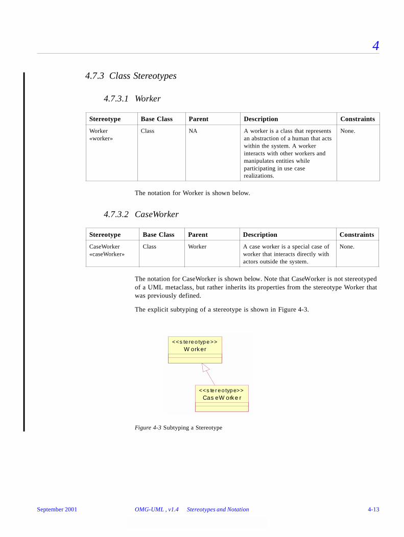
4
4.7.3 Class Stereotypes
4.7.3.1 Worker
The notation for Worker is shown below.
4.7.3.2 CaseWorker
The notation for CaseWorker is shown below. Note that CaseWorker is not stereotyped of a UML metaclass, but rather inherits its properties from the stereotype Worker that was previously defined.
The explicit subtyping of a stereotype is shown in Figure 4-3.
Figure 4-3 Subtyping a Stereotype
Stereotype Base Class Parent Description Constraints
Worker«worker»
Class NA A worker is a class that represents an abstraction of a human that acts within the system. A worker interacts with other workers and manipulates entities while participating in use case realizations.
None.
Stereotype Base Class Parent Description Constraints
CaseWorker«caseWorker»
Class Worker A case worker is a special case of worker that interacts directly with actors outside the system.
None.
W orker<<s te re o typ e >>
Cas eW orke r<<s te r e o typ e>>
September 2001 OMG-UML , v1.4 Stereotypes and Notation 4-13
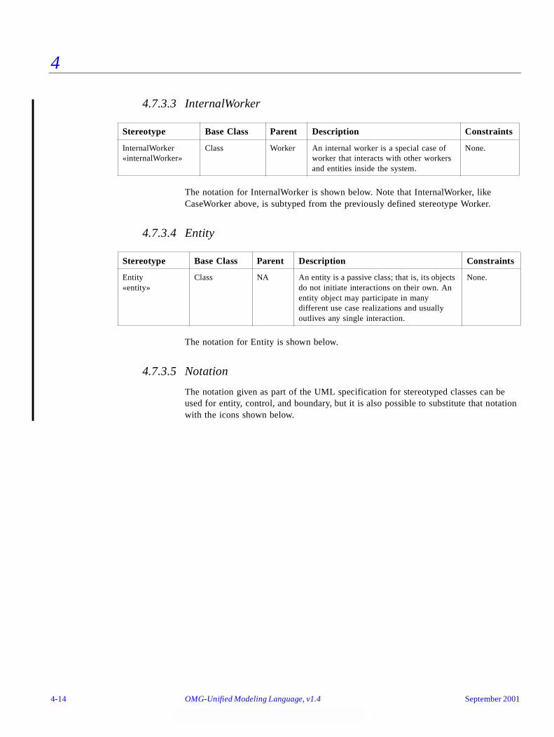
4
4.7.3.3 InternalWorker
The notation for InternalWorker is shown below. Note that InternalWorker, like CaseWorker above, is subtyped from the previously defined stereotype Worker.
4.7.3.4 Entity
The notation for Entity is shown below.
4.7.3.5 Notation
The notation given as part of the UML specification for stereotyped classes can be used for entity, control, and boundary, but it is also possible to substitute that notation with the icons shown below.
Stereotype Base Class Parent Description Constraints
InternalWorker«internalWorker»
Class Worker An internal worker is a special case of worker that interacts with other workers and entities inside the system.
None.
Stereotype Base Class Parent Description Constraints
Entity«entity»
Class NA An entity is a passive class; that is, its objects do not initiate interactions on their own. An entity object may participate in many different use case realizations and usually outlives any single interaction.
None.
4-14 OMG-Unified Modeling Language, v1.4 September 2001
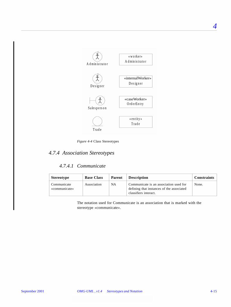
4
Figure 4-4 Class Stereotypes
4.7.4 Association Stereotypes
4.7.4.1 Communicate
The notation used for Communicate is an association that is marked with the stereotype «communicate».
Stereotype Base Class Parent Description Constraints
Communicate«communicate»
Association NA Communicate is an association used for defining that instances of the associated classifiers interact.
None.
O rd e rEn t ry« c a s e w o rke r»
T ra d e« e n t it y »
T ra d e
S a le s p e rs o n
A d m in is t ra to rA d m in is t ra to r
« w o rke r»
D e s ig n e rD e s ig n e r
« in te rn a l w o rke r»«internalWorker»
«caseWorker»
September 2001 OMG-UML , v1.4 Stereotypes and Notation 4-15
4
4.7.4.2 Subscribe
The notation used for Subscribe is an association that is marked with the stereotype «subscribe».
4.8 Well-Formedness Rules
The UML Specification relies on the use of well-formedness rules to express constraints on model elements, and this profile uses the same approach. The constraints applicable to the profile are added to the ones of the stereotyped base model elements, which cannot be changed.
4.8.1 Generalization
All the modeling elements in a generalization must be of the same stereotype; for example, a worker class may only inherit from other worker classes.
context Generalization inv:
let stNames : Set(Name) = self.child.stereotype->name
self.parent.stereotype->size>0) implies (if (self.parent.stereotype->name->includes(“worker”) then
((stNames->includes(“worker”) and(selfstNames->excludes(“case worker”) and(stNames->excludes(“internal worker”) and(stNames->excludes(“entity”))
else (if (self.parent.stereotype->name->includes(“case worker”) then
((stNames->includes(“case worker”) and(selfstNames->excludes(“worker”) and(stNames->excludes(“internal worker”) and(stNames->excludes(“entity”))
else (if (self.parent.stereotype->name->includes(“internal worker”)
then ((stNames->includes(“internal worker”) and(selfstNames->excludes(“case worker”) and(stNames->excludes(“worker”) and(stNames->excludes(“entity”))
else(if (self.parent.stereotype->name->includes(“entity”) then
((stNames->includes(“entity”) and
Stereotype Base Class Parent Description Constraints
Subscribe«subscribe»
Association NA A subscribe association between two classes states that objects of the source class (called the subscriber) will be notified when a particular event has occurred in objects of the target class (called the publisher). The association includes a specification of a set of events defining the event that causes the subscriber to be notified.
None.
4-16 OMG-Unified Modeling Language, v1.4 September 2001

4
(selfstNames->excludes(“case worker”) and(stNames->excludes(“internal worker”) and(self.child.stereotype->name->excludes(“worker”))))))
September 2001 OMG-UML , v1.4 Well-Formedness Rules 4-17

4
4-18 OMG-Unified Modeling Language, v1.4 September 2001
UML Model Interchange 5
Contents
This chapter contains the following sections.
5.1 Overview
UML model interchange is based on the Metaobject Facility (MOF) 1.3 Specification. The UML Semantics abstract syntax is mapped to a set of MOF packages called the UML Interchange Metamodel. The packages are available as an XML document called UML_1.4_Interchange_Metamodel.xml (OMG document ad/01-02-15) whose document type is based on the MOF 1.3 Model and the XML Metadata Interchange (XMI) 1.1 Specification.
Except for the Data_Types package, each package of the UML Interchange Metamodel defines a separate unit of compliance. The Core package defines the most basic level of compliance. The UML package, which is a cluster of all of the others, defines complete compliance.
Dependencies between the packages are shown in Figure 5-1. Each package imports whatever other packages it requires such that it can be directly deployed within a MOF facility. The packages can also be incorporated into other clusters in order to create other package groupings or to define extensions.
Section Title Page
“Overview” 5-1
“Model Interchange Using XMI” 5-22
“Model Interchange Using CORBA IDL” 5-24
September 2001 OMG-Unified Modeling Language, v1.4 5-1
5
The UML Interchange Metamodel closely follows the UML Semantics Metamodel as expressed in its abstract syntax. Changes are introduced as needed to conform to MOF requirements. Details are added to support XML and IDL generation. The following changes are made.
• Spaces in package names are changed to "_".
• Each unnamed association end is given its type's name with the first letter downcased.
• Associations in the UML Semantics Metamodel are unnamed, so names are generated by this pattern: "A_" followed by the first end's name followed by "_" and the second end's name.
• MOF references are added for most association ends in order to facilitate easy navigation. References are not added where they would create new package dependencies or where they would prevent linking to external models.
• MOF does not support association classes, so the ElementOwnership association class is removed and its attributes moved to ModelElement. Each other association class is changed into a class with each connection made into a separate association.
• Prefixes are added to enumeration literals to make them unique for IDL generation.
The Interchange Metamodel addresses semantic content of UML models and does not address diagram layout details. The metamodel can be extended to handle diagrams by subclassing the abstract class PresentationElement of the Core package. There is currently no standard extension for diagram interchange.
The Interchange Metamodel is shown using UML notation below. Figur e5-1 shows the separate packages and their dependencies. Figure 5-2 through Figure 5-21 show the classes, features, and associations of the metamodel.
5-2 OMG-Unified Modeling Language, v1.4 September 2001
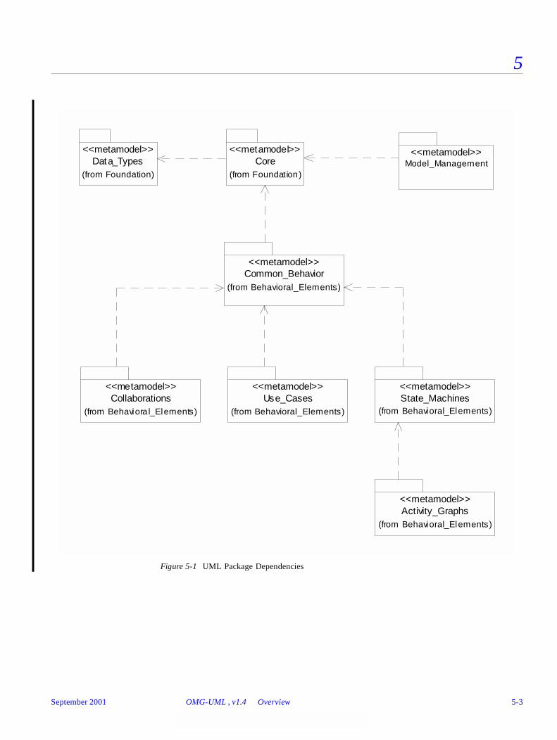
5
Figure 5-1 UML Package Dependencies
Data_Types<<metamodel>>
(from Foundation)
Core<<metamodel>>
(from Foundation)
Common_Behavior<<metamodel>>
(from Behavioral_Elements)
Use_Cases<<metamodel>>
(from Behavioral_Elements)
State_Machines<<metamodel>>
(from Behavioral_Elements)Collaborations
<<metamodel>>
(from Behaviora l_Elements)
Activity_Graphs<<metamodel>>
(from Behavioral_Elements)
Model_Management<<metamodel>>
September 2001 OMG-UML , v1.4 Overview 5-3

5
Figure 5-2 Core Package - Backbone
Element
GeneralizableElement
isRoot : BooleanisLeaf : BooleanisAbstract : Boolean/ generalization : Generalization
AttributeinitialValue : Expression/ associationEnd : AssociationEnd
Method
body : ProcedureExpression/ specification : Operation
Operation
concurrency : CallConcurrencyKindisRoot : BooleanisLeaf : BooleanisAbstract : Booleanspecification : String
*1
+method
*
+specification
1
Namespace
/ ownedElement : ModelElement
Constraintbody : BooleanExpression/ constrainedElement : ModelElement
ModelElement
name : Namevisibility : VisibilityKindisSpecification : Boolean/ namespace : Namespace/ clientDependency : Dependency/ constraint : Constraint/ targetFlow : Flow/ sourceFlow : Flow/ comment : Comment/ templateParameter : TemplateParameter/ stereotype : Stereotype/ taggedValue : TaggedValue
0..1
*
+namespace0..1
+ownedElement *
*
*
+constraint*
+constrainedElement
* {ordered}
BehavioralFeature
isQuery : Boolean/ parameter : Parameter
Feature
ownerScope : ScopeKind/ owner : Class ifier
StructuralFeature
multiplicity : Multiplicitychangeability : ChangeableKindtargetScope : ScopeKindordering : OrderingKind/ type : Classifier
Parameter
defaultValue : Expressionkind : ParameterDirectionKind/ behavioralFeature : BehavioralFeature/ type : Classifier
0..1
*
+behavioralFeature
0..1
+parameter*{ordered}
Classifier
/ feature : Feature/ powertypeRange : Generalization
*
0..1+feature
* {ordered} +owner
0..1
*
1
+typedFeature
*
+type 1
*
1
+typedParameter*
+type
1
5-4 OMG-Unified Modeling Language, v1.4 September 2001
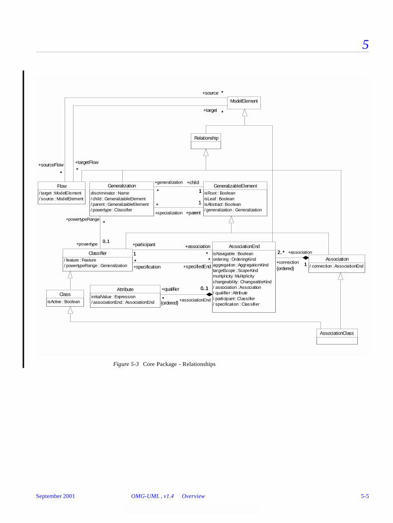
5
Figure 5-3 Core Package - Relationships
AssociationClass
Class
isActive : Boolean
Relationship
Association/ connection : AssociationEnd
Attribute
initialValue : Expression/ associationEnd : AssociationEnd
AssociationEnd
isNavigable : Booleanordering : OrderingKindaggregation : AggregationKindtargetScope : ScopeKindmultipl icity : Multiplicitychangeability : ChangeableKind/ association : Association/ qual ifier : Attribute/ participant : Classifier/ specification : Classifier
2..*
1+connection
2..*
{ordered}
+association
1
*
0..1+qualifier
*{ordered}
+associationEnd
0..1
GeneralizableElementisRoot : BooleanisLeaf : BooleanisAbstract : Boolean/ generalization : Generalization
Classifier/ feature : Feature/ powertypeRange : Generalization
1 *
+participant
1
+association
***
+specifiedEnd*
+specification*
Generalization
discriminator : Name/ child : GeneralizableElement/ parent : GeneralizableElement/ powertype : Classifier
* 1
+generalization
*
+child
1
1*
+parent
1
+specialization
*
0..1
*
+powertype0..1
+powertypeRange*
Flow/ target : ModelElement/ source : ModelElement
ModelElement
*
*
+sourceFlow
*
+source *
*
*
+targetFlow
*
+target *
September 2001 OMG-UML , v1.4 Overview 5-5

5
Figure 5-4 Core Package - Dependencies
Usage PermissionAbstractionmapping : MappingExpression
Binding/ argument : TemplateArgument
ModelElementname : Namevisibility : VisibilityKindisSpecification : Boolean/ namespace : Namespace/ clientDependency : Dependency/ constraint : Constraint/ targetFlow : Flow/ sourceFlow : Flow/ comment : Comment/ templateParameter : TemplateParameter/ stereotype : Stereotype/ taggedValue : TaggedValue
Dependency/ client : ModelElement/ supplier : ModelElement
1..* *
+supplier
1..*
+supplierDependency
*
1..* *
+client
1..*
+clientDependency
*
Relationship
5-6 OMG-Unified Modeling Language, v1.4 September 2001
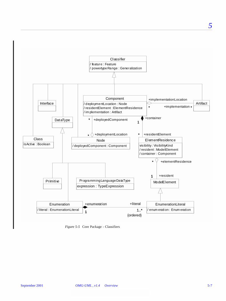
5
Figure 5-5 Core Package - Classifiers
Classi fier/ feature : Feature/ powertypeRange : Generalization
ClassisActive : Boolean
DataType
Interface
Primitive
Enumeration
/ literal : EnumerationLiteral
EnumerationLiteral
/ enum erati on : Enum eration1 1..*
+enumerat ion
1
+literal
1..*{ordered}
ProgrammingLanguageDataType
expression : TypeExpressionModelElement
Node
/ deployedComponent : Component
ElementResidence
vis ibility : Vis ibilityKind/ resident : ModelElement/ container : Component
1
*
+resident1
+elementResidence*
ArtifactComponent
/ deploymentLocation : Node/ residentElement : ElementResidence/ im plementation : Artifact
*
*
+deploymentLocation*
+deployedComponent*1
*
+container1
+residentElement*
** +implementation *
+implementationLocation
*
September 2001 OMG-UML , v1.4 Overview 5-7
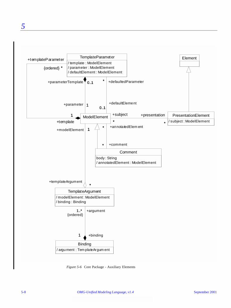
5
Figure 5-6 Core Package - Auxiliary Elements
Element
PresentationElement/ subject : ModelElement
Binding/ argument : Tem plateArgum ent
Commentbody : String/ annotatedElement : ModelElement
TemplateParameter/ template : ModelElement/ parameter : ModelElement/ defaultElement : ModelElement
TemplateArgument/ modelElement : ModelElement/ binding : Binding
1
1..*
+binding1
+argument1..*{ordered}
ModelElement
**
+presentation
*
+subject
*
*
*
+comment*
+annotatedElem ent*
0..1
*
+defaultElement0..1
+defaultedParameter*
1
*
+template
1
+templateParameter
*{ordered}
1
0..1
+parameter 1
+parameterTemplate 0..1
1
*
+modelElement
+templateArgument
1
*
5-8 OMG-Unified Modeling Language, v1.4 September 2001
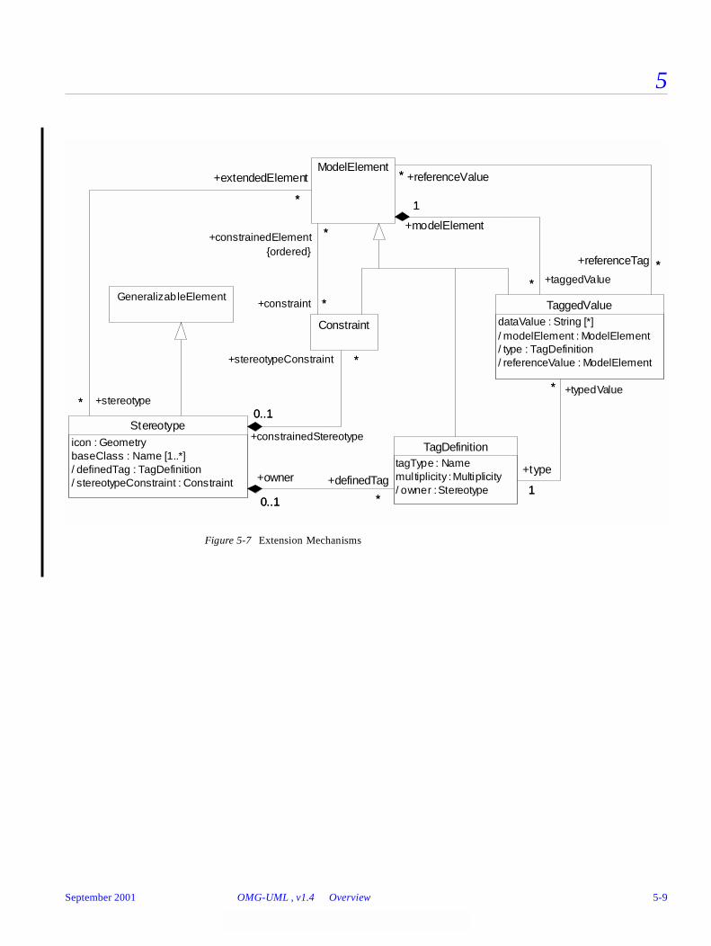
5
Figure 5-7 Extension Mechanisms
GeneralizableElement
Stereotypeicon : GeometrybaseClass : Name [1..*]/ definedTag : TagDefinition/ stereotypeConstraint : Constraint
Constraint
0..1
*
+constrainedStereotype
0..1
+stereotypeConstraint *
TagDefinitiontagType : Namemultiplicity : Multiplicity/ owner : Stereotype
*0..1
+definedTag
*
+owner
0..1
ModelElement
*
*
+stereotype*
+extendedElement
*
*
*
+constrainedElement *
{ordered}
+constraint * TaggedValuedataValue : String [*]/ modelElement : ModelElement/ type : TagDefinition/ referenceValue : ModelElement
1
*
+type
1
+typedValue*
1
*
+modelElement
1
+taggedValue*
*
*
+referenceValue*
+referenceTag *
September 2001 OMG-UML , v1.4 Overview 5-9

5
Figure 5-8 Data Types
AggregationKind
ak_noneak_aggregateak_composite
<<enumeration>>
Boolean
falsetrue
<<datatype>>
ChangeableKind
ck_changeableck_frozenck_addOnly
<<enumeration>>
Name<<datatype>>
Integer<<datatype>>
ParameterDirectionKind
pdk_inpdk_inoutpdk_outpdk_return
<<enumeration>>
ScopeKindsk_instancesk_classifier
<<enumeration>>
String<<datatype>>
VisibilityKind
vk_publicvk_protectedvk_privatevk_package
<<enumeration>>
PseudostateKindpk_choicepk_deepHistorypk_forkpk_initialpk_joinpk_junctionpk_shallowHistory
<<enumeration>>
CallConcurrencyKindcck_sequentialcck_guardedcck_concurrent
<<enumeration>>
MultiplicityRangelower : Integerupper : UnlimitedInteger/ multiplicity : Multiplicity
Multiplicity
1..*
1
+range1..*
+multiplicity1
UnlimitedInteger<<datatype>>
LocationReference<<datatype>>
OrderingKindok_unorderedok_ordered
<<enumeration>>
Geometry<<datatype>>
5-10 OMG-Unified Modeling Language, v1.4 September 2001
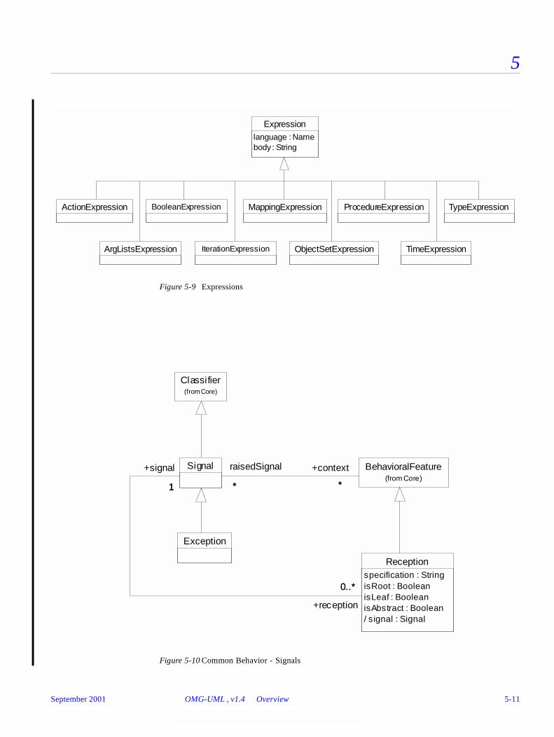
5
Figure 5-9 Expressions
Figure 5-10 Common Behavior - Signals
BooleanExpression
Expressionlanguage : Namebody : String
ObjectSetExpression TimeExpression
ActionExpression
IterationExpression
TypeExpression
ArgListsExpression
MappingExpression ProcedureExpression
Exception
Receptionspecification : StringisRoot : BooleanisLeaf : BooleanisAbstract : Boolean/ signal : Signal
BehavioralFeature(from Core)
Signal
1
0..*
+signal
1
+reception
0..*
**
+context
*
raisedSignal
*
Classifier(from Core)
September 2001 OMG-UML , v1.4 Overview 5-11

5
Figure 5-11 Common Behavior - Actions
DestroyAction
UninterpretedAction
ModelElement(f rom Core)
CreateAction
/ instantiation : Classifier
Classifier(from Core)
*
1
+createAction *
+instantiation1
ReturnAction
TerminateActionCallAction
/ operation : Operation
Operation(f rom Core)
*
1
+callAction *
+operation 1
SendAction
/ signal : Signal
Signal
*
1
+sendAction*
+signal1
Argumentvalue : Expression/ action : Action
ActionSequence
/ action : Action
Act ion
recurrence : IterationExpressiontarget : ObjectSetExpressionisAsynchronous : Booleanscript : ActionExpression/ actualArgument : Argument/ actionSequence : ActionSequence
*
0..1
+actualArgum ent*{ordered}
+action0..1
0..1 *
+actionSequence
0..1
+action
*{ordered}
5-12 OMG-Unified Modeling Language, v1.4 September 2001

5
Figure 5-12 Common Behavior - Instances
DataValue Object
ModelElement(from Core)
NodeInstance/ resident : ComponentInstance
Attribute(f rom Core)
ComponentInstance/ nodeInstance : NodeInstance/ resident : Instance
Classifier(from Core)
AttributeLink
/ attribute : Attr ibute/ value : Instance/ ins tance : Ins tance/ linkEnd : L inkEnd
Instance
/ classifier : Classifier/ linkEnd : LinkEnd/ slot : AttributeLink/ componentInstance : ComponentInstance/ ownedInstance : Instance/ ownedLink : Link
Stimulus/ argument : Instance/ sender : Instance/ receiver : Instance/ communicationLink : Link/ dispatchAction : Action
Action
SubsystemInstance
+nodeInstance
0..1
+attribute
1
+resident**
0..1
+classifier
1..*
+attributeLink
**
1
+slot**
*
0..1
+resident
*
+componentInstance 0..1
+instance*
1..**
+instance
0..10..1
*
+value 1
*
1
+ownedInstance
**
0..1
+owner
0..1
+argument *
{ordered}+sender1 +receiver1
**
*
**
1
*
1
*
+stimulus
*+dispatchAction
1
*
1
September 2001 OMG-UML , v1.4 Overview 5-13
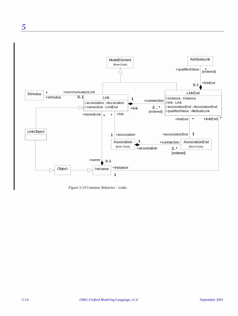
5
Figure 5-13 Common Behavior - Links
LinkObject
Object
ModelElement(from Core)
AssociationEnd(from Core)
AttributeLink
Association(from Core)
LinkEnd/ instance : Instance/ link : Link/ associationEnd : AssociationEnd/ qualifiedValue : AttributeLink
Link/ as sociation : Ass ociation/ connection : LinkEnd
Instance
Stimulus
+connection
2..*{ordered}
+associationEnd 1
+qualifiedValue *{ordered}
+association
1
2..*
1
+association1
+linkEnd *
1
*
+linkEnd0..10..1
*
+linkEnd *+link*
1
*
1
2 .. *+link
1 +connection
2 .. *{ordered}
+ownedLink *
+communicationLink
0..1
+instance
11
*
+owner 0..1
*
0..1
+stimulus**
0..1
5-14 OMG-Unified Modeling Language, v1.4 September 2001
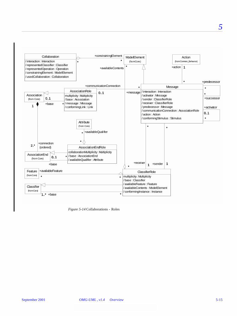
5
Figure 5-14 Collaborations - Roles
Attribute(f rom Core)
AssociationEndRolecollaborationMultiplicity : Multiplicity/ base : AssociationEnd/ availableQualifier : Attribute
*
*
*
+availableQuali fier*
AssociationEnd(from Core) 0..1 *
+base
0..1 *
Association(from Core)
2..*
1
+connection2..* {ordered}
1
Action(from Common_Behavior)
AssociationRolemultiplicity : Multiplicity/ base : Association/ message : Message/ conformingLink : Link
0..1
*+base
0..1
*
Collaboration/ interaction : Interaction/ representedClassifier : Classifier/ representedOperation : Operation/ constrainingElement : ModelElement/ usedCollaboration : Collaboration
Feature(from Core)
Message/ interaction : Interaction/ activator : Message/ sender : ClassifierRole/ receiver : ClassifierRole/ predecessor : Message/ communicationConnection : AssociationRole/ action : Action/ conformingStimulus : Stimulus *
0..1
*
+activator
0..1
*
*
+successor*
+predecessor
*
1
*
+action 1
*
*
0..1 +message*
+communicationConnection
0..1
ModelElement(f rom Core)* **
+constrainingElement
*
Classifier(from Core)
ClassifierRolemultiplicity : Multiplicity/ base : Classifier/ availableFeature : Feature/ availableContents : ModelElement/ conformingInstance : Instance
** *
+availableFeature
*
1
*
+sender 1
**
1
*
+receiver1*
*
*
+availableContents *
1..* *+base1..* *
September 2001 OMG-UML , v1.4 Overview 5-15
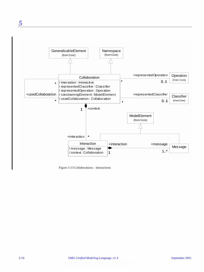
5
Figure 5-15 Collaborations - Interactions
GeneralizableElement(from Core)
Namespace(from Core)
MessageInteraction
/ message : Message/ context : Collaboration 1 1..*
+interaction
1
+message
1..*
Operation(f rom Core)
Collaboration/ interaction : Interacti on/ representedClassi fi er : Classi fier/ representedOperation : Operation/ constrainingElement : ModelElement/ usedCol laboration : Collaboration
1
*
+context1
+interaction *
0..1*
+representedOperation
0..1*
*
*
+usedCollaboration
*
*
Classifier(from Core)
* 0..1*
+representedClassifier
0..1
ModelElement(from Core)
5-16 OMG-Unified Modeling Language, v1.4 September 2001

5
Figure 5-16 Collaborations - Instances
Message
Stimulus(f rom Common_Behavior)
*
*
+playedRole*
+conformingStimulus*
Interaction/ mess age : Message/ context : Collaboration1..*
1+message
1..* +interaction
1
ClassifierRolemultipl icity : Mul tiplicity/ base : Classifier/ avai lableFeature : Feature/ avai lableContents : ModelElem ent/ conform ingIns tance : Instance
AssociationRolemultiplicity : Multiplicity/ base : Association/ message : Message/ conformingLink : Link
InteractionInstanceSet/ context : CollaborationInstanceSet/ interaction : Interaction/ participatingStim ulus : Stimulus
0..1
*
+interaction0..1
*
*1..* *
+participatingStimulus
1..*
Collaboration/ interaction : Interaction/ representedClassifier : Classifier/ representedOperation : Operation/ constrainingElement : ModelElement/ usedCollaboration : Collaboration
*
1+interaction
* +context
1
Instance* *
+playedRole
*
+conformingInstance
*
Link* *
+playedRole
*
+conformingLink
*
CollaborationInstanceSet/ interactionInstanceSet : InteractionInstanceSet/ collaboration : Collaboration/ participatingInstance : Instance/ participatingLink : Link/ constrainingElement : ModelElement
1
* +context
1+interactionInstanceSet
*
0..1
*
+collaboration 0..1
+co llaborationInstanceSet *
*
1..*
*
+participatingInstance 1..*
*
*
+participatingL ink *
*
ModelElement(from Core)
*
*
*
+constrainingElement
*
+interactionInstanceSet
September 2001 OMG-UML , v1.4 Overview 5-17
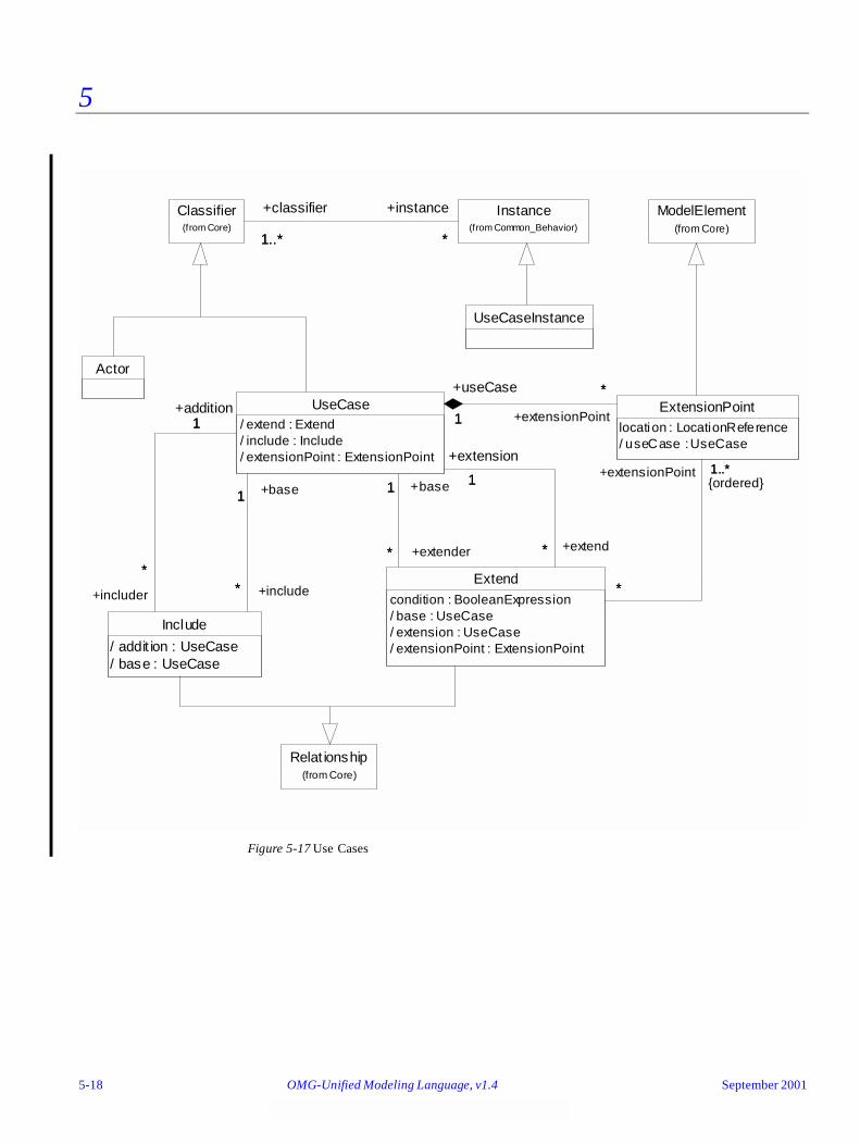
5
Figure 5-17 Use Cases
UseCaseInstance
Actor
Classifier(from Core)
Instance(from Common_Behavior)
1..* *
+classifier
1..*
+instance
*
ModelElement(from Core)
Include
/ addit ion : UseCase/ base : UseCase
UseCase/ extend : Extend/ include : Include/ extensionPoint : ExtensionPoint
*
1
+includer
*
+addition1
*
1
+include*
+base1
ExtensionPointlocation : LocationReference/ useCase : UseCase
*
1 +extensionPoint
*+useCase
1
Extendcondition : BooleanExpression/ base : UseCase/ extension : UseCase/ extensionPoint : ExtensionPoint
1
*
+base1
+extender*
1
*
+extension
1
+extend*
1..*
*
+extensionPoint 1..*{ordered}
*
Relat ionship(from Core)
5-18 OMG-Unified Modeling Language, v1.4 September 2001
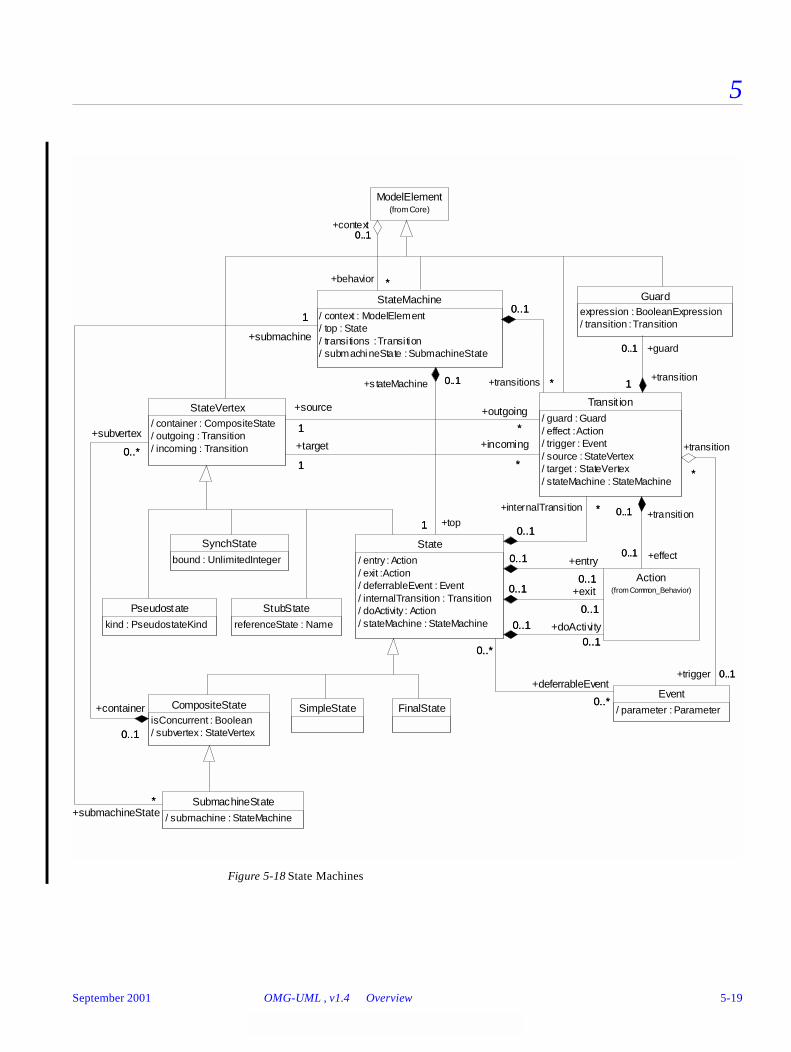
5
Figure 5-18 State Machines
Pseudostate
kind : PseudostateKind
SimpleState
SynchState
bound : UnlimitedInteger
StubState
referenceState : Name
FinalState
SubmachineState
/ submachine : StateMachine
ModelElement(from Core)
Guardexpression : BooleanExpression/ transition : Transition
Event
/ parameter : Parameter
Action(from Common_Behavior)
State
/ entry : Action/ exit : Action/ deferrableEvent : Event/ internalTransition : Transition/ doActivity : Action/ stateMachine : StateMachine
0..*
0..*
0..*
+deferrableEvent
0..*
0..1
0..1
0..1 +entry
0..10..1
0..1
0..1 +exit
0..1
0..1
0..1
0..1 +doActivity0..1
StateMachine
/ context : ModelElement/ top : State/ transitions : Transition/ submachineState : SubmachineState
1
0..1
+top1
+s tateMachine 0..1
*
1
+submachineState*
+submachine
1
*
0..1
+behavior *
+context0..1
CompositeStateisConcurrent : Boolean/ subvertex : StateVertex
Transit ion
/ guard : Guard/ effect : Action/ trigger : Event/ source : StateVertex/ target : StateVertex/ stateMachine : StateMachine
1
0..1
+transition1
+guard0..1
0..1
*
+trigger 0..1
+transition
*
0..1
0..1
+effect0..1
+transition0..1*
0..1
+internalTransition *
0..1
*
0..1
+transitions *
0..1
StateVertex/ container : CompositeState/ outgoing : Transition/ incoming : Transition0..*
0..1
+subvertex
0..*
+container
0..1
1 *
+source
1
+outgoing
*
1 *
+target
1
+incoming
*
September 2001 OMG-UML , v1.4 Overview 5-19

5
Figure 5-19 State Machines - Events
TimeEvent
when : TimeExpression
ChangeEvent
changeExpression : BooleanExpression
Operation(f rom Core)
CallEvent
/ operation : Operation
1
*
+operation 1
+occurrence *
SignalEvent
/ signal : Signal
Signal(f rom Common_Behav ior)
*
1
+occurrence*
+signal 1
Parameter(from Core)
Event
/ parameter : Parameter* 0..1
+parameter
* {ordered}
+event
0..1
ModelElement(from Core)
5-20 OMG-Unified Modeling Language, v1.4 September 2001
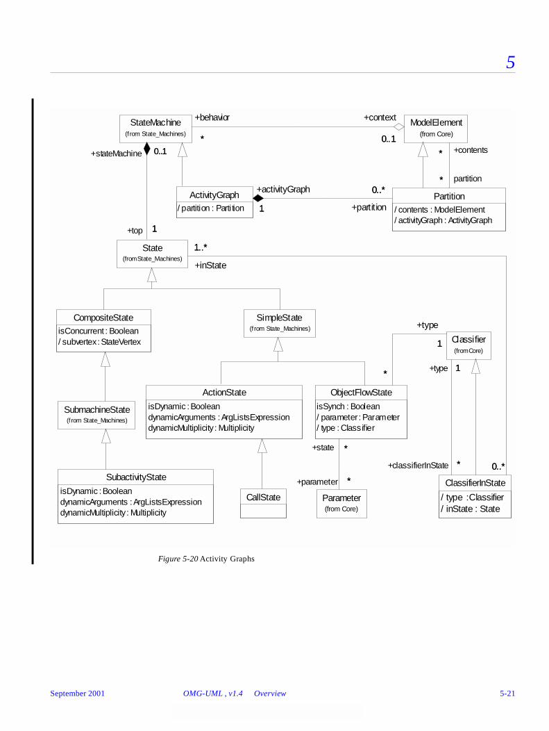
5
Figure 5-20 Activity Graphs
ActionState
isDynamic : BooleandynamicArguments : ArgListsExpressiondynamicMultiplicity : Multiplicity
SimpleState(from State_Machines)
SubactivityState
isDynamic : BooleandynamicArguments : ArgListsExpressiondynamicMultiplicity : Multiplicity
SubmachineState(from State_Machines)
CompositeStateisConcurrent : Boolean/ subvertex : StateVertex
CallState
ActivityGraph/ partition : Parti tion
Partition/ contents : ModelElement/ activityGraph : ActivityGraph
1
0..*+activityGraph
1 +partition
0..*
ModelElement(from Core)
*
*
+contents*
partition*
StateMachine(from State_Machines)
0..1*
+context
0..1
+behavior
*
State(from State_Machines)
0..1
1
+stateMachine 0..1
+top 1
ClassifierInState
/ type : Classifier/ inState : State
0..*
1..*
0..*
+inState
1..*
Parameter(from Core)
Classifier(from Core)
1
*
+type 1
+classifierInState *
ObjectFlowState
isSynch : Boolean/ parameter : Parameter/ type : Classifier
*
*
+parameter *
+state *
1
*
+type
1
*
September 2001 OMG-UML , v1.4 Overview 5-21
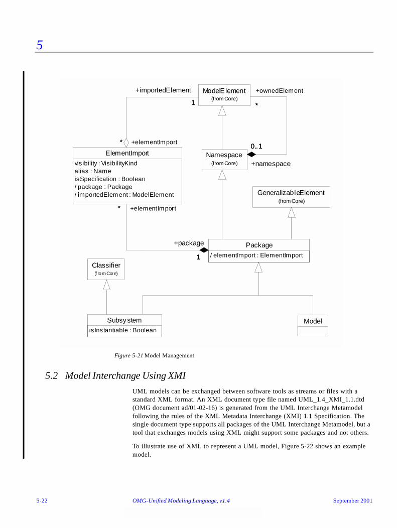
5
Figure 5-21 Model Management
5.2 Model Interchange Using XMI
UML models can be exchanged between software tools as streams or files with a standard XML format. An XML document type file named UML_1.4_XMI_1.1.dtd (OMG document ad/01-02-16) is generated from the UML Interchange Metamodel following the rules of the XML Metadata Interchange (XMI) 1.1 Specification. The single document type supports all packages of the UML Interchange Metamodel, but a tool that exchanges models using XML might support some packages and not others.
To illustrate use of XML to represent a UML model, Figure 5-22 shows an example model.
GeneralizableElement(from Core)
SubsystemisInstantiable : Boolean
Model
Classifier(f rom Core)
Namespace(from Core)
ModelElement(from Core)
*
0..1
+ownedElement
*
+namespace
0..1
Package/ elementImport : ElementImport
ElementImportvisibility : VisibilityKindalias : NameisSpecification : Boolean/ package : Package/ importedElement : ModelElement
1
*
+importedElement
1
+elementImport*
1
*
+package
1
+elementImport*
5-22 OMG-Unified Modeling Language, v1.4 September 2001

5
Figure 5-22Example: Employment Model
The model shown above is expressed in XML below.
<?xml version='1.0' encoding='ISO-8859-1' ?><!DOCTYPE XMI SYSTEM 'UML_1.4_XMI_1.1.dtd'><XMI xmi.version='1.2' xmlns:UML='omg.org/UML/1.4'> <XMI.header> <XMI.metamodel xmi.name='UML' xmi.version='1.4'/> </XMI.header> <XMI.content> <UML:Model xmi.id='S.1' name='Employment Model' visibility='public' isSpecification='false' isRoot='false' isLeaf='false' isAbstract='false'> <UML:Namespace.ownedElement> <UML:Class xmi.id='S.2' name='Person' visibility='public' isSpecification='false' namespace='S.1' isRoot='true' isLeaf='true' isAbstract='false' isActive='false'/> <UML:Class xmi.id='S.3' name='Business' visibility='public' isSpecification='false' namespace='S.1' isRoot='true' isLeaf='true' isAbstract='false' isActive='false'/> <UML:Association xmi.id='G.1' name='Employment' visibility='public' isSpecification='false' isRoot='false' isLeaf='false' isAbstract='false'> <UML:Association.connection> <UML:AssociationEnd name='employer' visibility='public' isSpecification='false' isNavigable='true' ordering='unordered' aggregation='none' targetScope='instance' changeability='changeable' participant='S.3' association='G.1'> <UML:AssociationEnd.multiplicity> <UML:Multiplicity> <UML:Multiplicity.range> <UML:MultiplicityRange lower='0' upper='-1'/> </UML:Multiplicity.range> </UML:Multiplicity> </UML:AssociationEnd.multiplicity> </UML:AssociationEnd> <UML:AssociationEnd name='employee' visibility='public' isSpecification='false' isNavigable='true' ordering='unordered' aggregation='none' targetScope='instance' changeability='changeable' participant='S.2' association='G.1'> <UML:AssociationEnd.multiplicity> <UML:Multiplicity> <UML:Multiplicity.range> <UML:MultiplicityRange lower='0' upper='-1'/> </UML:Multiplicity.range> </UML:Multiplicity> </UML:AssociationEnd.multiplicity> </UML:AssociationEnd> </UML:Association.connection> </UML:Association> </UML:Namespace.ownedElement> </UML:Model> </XMI.content></XMI>
Person Business
**
Employment+employer+employee
**
September 2001 OMG-UML , v1.4 Model Interchange Using XMI 5-23
5
5.3 Model Interchange Using CORBA IDL
CORBA interfaces can be used for creating, accessing, and manipulating UML models. The MOF Specification's Reflective module provides generic interfaces for accessing all objects of a model. Tailored interfaces extend the generic interfaces. One tailored IDL module is generated from each UML Interchange Metamodel package following rules defined in the MOF Specification. The tailored interfaces support fine-grained creation, access, and modification of model elements with type safety in terms of the UML Interchange Metamodel. Support of tailored interfaces is optional. A facility might support some packages and not others.
The module files are combined in a file named UML_1.4_CORBA_IDL.zip (OMG document ad/01-02-17).
The behavior of a CORBA Facility is defined by the MOF Specification for both reflective and tailored interfaces. Additionally, a UML CORBA Facility must provide access to UML Standard Elements (stereotypes, constraints, and tags) documented in chapter 2, UML Semantics.
5-24 OMG-Unified Modeling Language, v1.4 September 2001
Object Constraint Language Specification 6
This chapter introduces and defines the Object Constraint Language (OCL), a formal language to express side-effect-free constraints.
Contents
This chapter contains the following topics.
6.1 Overview
This chapter introduces and defines the Object Constraint Language (OCL), a formal language used to express constraints. These typically specify invariant conditions that must hold for the system being modeled. Note that when the OCL expressions are evaluated, they do not have side effects; that is, their evaluation cannot alter the state of
Topic Page
“Overview” 6-1
“Introduction” 6-3
“Relation to the UML Metamodel” 6-4
“Basic Values and Types” 6-7
“Objects and Properties” 6-11
“Collection Operations” 6-22
“The Standard OCL Package” 6-28
“Predefined OCL Types” 6-29
“Grammar” 6-45
September 2001 OMG-Unified Modeling Language, v1.4 6-1
6
the corresponding executing system. In addition, to specifying invariants of the UML metamodel, UML modelers can use OCL to specify application-specific constraints in their models.
OCL is used in the UML Semantics chapter to specify the well-formedness rules of the metaclasses comprising the UML metamodel. A well-formedness rule in the static semantics chapters in the UML Semantics section normally contains an OCL expression, specifying an invariant for the associated metaclass. The grammar for OCL is specified at the end of this chapter. A parser generated from this grammar has correctly parsed all the constraints in the UML Semantics section, a process which improved the correctness of the specifications for OCL and UML.
6.1.1 Why OCL?
A UML diagram, such as a class diagram, is typically not refined enough to provide all the relevant aspects of a specification. There is, among other things, a need to describe additional constraints about the objects in the model. Such constraints are often described in natural language. Practice has shown that this will always result in ambiguities. In order to write unambiguous constraints, so-called formal languages have been developed. The disadvantage of traditional formal languages is that they are usable to persons with a strong mathematical background, but difficult for the average business or system modeler to use.
OCL has been developed to fill this gap. It is a formal language that remains easy to read and write. It has been developed as a business modeling language within the IBM Insurance division, and has its roots in the Syntropy method.
OCL is a pure expression language; therefore, an OCL expression is guaranteed to be without side effect. When an OCL expression is evaluated, it simply returns a value. It cannot change anything in the model. This means that the state of the system will never change because of the evaluation of an OCL expression, even though an OCL expression can be used to specify a state change (for example, in a post-condition).
OCL is not a programming language; therefore, it is not possible to write program logic or flow control in OCL. You cannot invoke processes or activate non-query operations within OCL. Because OCL is a modeling language in the first place, not everything in it is promised to be directly executable.
OCL is a typed language, so that each OCL expression has a type. To be well formed, an OCL expression must conform to the type conformance rules of the language. For example, you cannot compare an Integer with a String. Each Classifier defined within a UML model represents a distinct OCL type. In addition, OCL includes a set of supplementary predefined types (these are described in Section 6.8, “Predefined OCL Types,” on page 6-29).
As a specification language, all implementation issues are out of scope and cannot be expressed in OCL.
The evaluation of an OCL expression is instantaneous. This means that the states of objects in a model cannot change during evaluation.
6-2 OMG-Unified Modeling Language, v1.4 September 2001

6
6.1.2 Where to Use OCL
OCL can be used for a number of different purposes:
• To specify invariants on classes and types in the class model
• To specify type invariant for Stereotypes
• To describe pre- and post conditions on Operations and Methods
• To describe Guards
• As a navigation language
• To specify constraints on operations
Within the UML Semantics chapter, OCL is used in the well-formedness rules as invariants on the metaclasses in the abstract syntax. In several places, it is also used to define ‘additional’ operations which are used in the well-formedness rules. Starting with UML 1.4, these additional operations can be formally defined using «definition» constraints and let-expressions.
6.2 Introduction
6.2.1 Legend
Text written in the courier typeface as shown below is an OCL expression.
'This is an OCL expression'
The context keyword introduces the context for the expression. The keyword inv, pre and post denote the stereotypes, respectively «invariant», «precondition», and «postcondition», of the constraint. The actual OCL expression comes after the colon.
context TypeName inv:
'this is an OCL expression with stereotype <<invariant>> i n the
context of TypeName' = 'another string'
In the examples. the keywords of OCL are written in boldface in this document. The boldface has no formal meaning, but is used to make the expressions more readable in this document. OCL expressions are written using ASCII characters only.
Words in Italics within the main text of the paragraphs refer to parts of OCL expressions.
6.2.2 Example Class Diagram
Figure 6-1 on page 6-4 is used in the examples in this document.
September 2001 OMG-UML , v1.4 Introduction 6-3
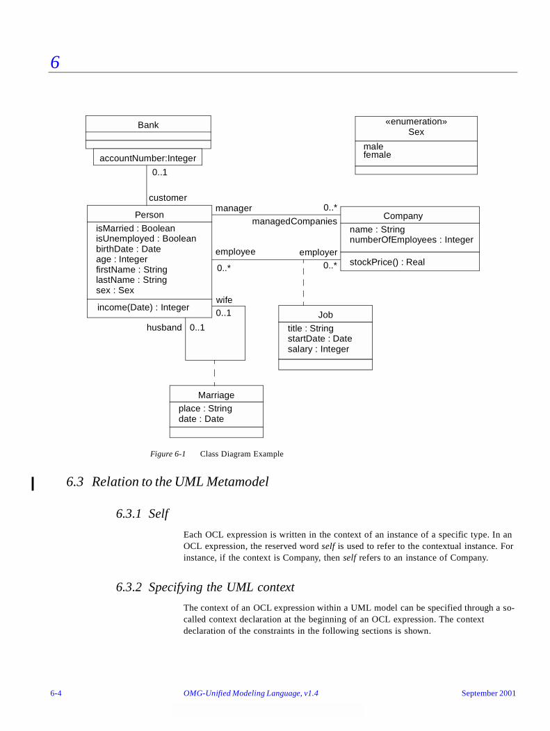
6
Figure 6-1 Class Diagram Example
6.3 Relation to the UML Metamodel
6.3.1 Self
Each OCL expression is written in the context of an instance of a specific type. In an OCL expression, the reserved word self is used to refer to the contextual instance. For instance, if the context is Company, then self refers to an instance of Company.
6.3.2 Specifying the UML context
The context of an OCL expression within a UML model can be specified through a so-called context declaration at the beginning of an OCL expression. The context declaration of the constraints in the following sections is shown.
Person
isMarried : BooleanisUnemployed : BooleanbirthDate : Dateage : IntegerfirstName : StringlastName : Stringsex : Sex
income(Date) : Integer
accountNumber:Integer
Bank
0..1
customer
Company
name : StringnumberOfEmployees : Integer
stockPrice() : Real
manager 0..*
managedCompanies
employee employer
wife
husband 0..1
0..1
0..*0..*
Job
title : StringstartDate : Datesalary : Integer
Marriage
place : Stringdate : Date
malefemale
«enumeration»Sex
6-4 OMG-Unified Modeling Language, v1.4 September 2001

6
If the constraint is shown in a diagram with the proper stereotype and the dashed lines to connect it to its contextual element, there is no need for an explicit context declaration in the test of the constraint. The context declaration is optional.
6.3.3 Invariants
The OCL expression can be part of an Invariant which is a Constraint stereotyped as an «invariant». When the invariant is associated with a Classifier, the latter is referred to as a “type” in this chapter. An OCL expression is an invariant of the type and must be true for all instances of that type at any time. (Note that all OCL expressions that express invariants are of the type Boolean.)
For example, if in the context of the Company type in Figure 6-1 on page 6-4, the following expression would specify an invariant that the number of employees must always exceed 50:
self.numberOfEmployees > 50
where self is an instance of type Company. (We can view self as the object from where we start the expression.) This invariant holds for every instance of the Company type.
The type of the contextual instance of an OCL expression, which is part of an invariant, is written with the context keyword, followed by the name of the type as follows. The label inv: declares the constraint to be an «invariant» constraint.
context Company inv:
self.numberOfEmployees > 50
In most cases, the keyword self can be dropped because the context is clear, as in the above examples. As an alternative for self, a different name can be defined playing the part of self:
context c : Company inv:
c.numberOfEmployees > 50
This invariant is equivalent to the previous one.
Optionally, the name of the constraint may be written after the inv keyword, allowing the constraint to be referenced by name. In the following example the name of the constraint is enoughEmployees. In the UML metamodel, this name is an attribute of the metaclass Constraint that is inherited from ModelElement.
context c : Company inv enoughEmployees:
c.numberOfEmployees > 50
6.3.4 Pre- and Postconditions
The OCL expression can be part of a Precondition or Postcondition, corresponding to «precondition» and «postcondition» stereotypes of Constraint associated with an Operation or Method. The contextual instance self then is an instance of the type that owns the operation or method as a feature. The context declaration in OCL uses the
September 2001 OMG-UML , v1.4 Relation to the UML Metamodel 6-5
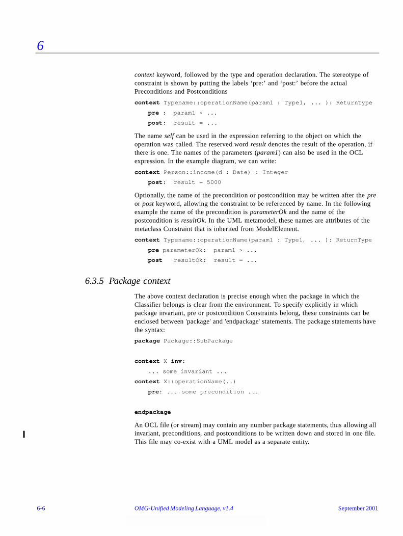
6
context keyword, followed by the type and operation declaration. The stereotype of constraint is shown by putting the labels ‘pre:’ and ‘post:’ before the actual Preconditions and Postconditions
context Typename::operationName(param1 : Type1, ... ): ReturnType
pre : param1 > ...
post: result = ...
The name self can be used in the expression referring to the object on which the operation was called. The reserved word result denotes the result of the operation, if there is one. The names of the parameters (param1) can also be used in the OCL expression. In the example diagram, we can write:
context Person::income(d : Date) : Integer
post: result = 5000
Optionally, the name of the precondition or postcondition may be written after the pre or post keyword, allowing the constraint to be referenced by name. In the following example the name of the precondition is parameterOk and the name of the postcondition is resultOk. In the UML metamodel, these names are attributes of the metaclass Constraint that is inherited from ModelElement.
context Typename::operationName(param1 : Type1, ... ): ReturnType
pre parameterOk: param1 > ...
post resultOk: result = ...
6.3.5 Package context
The above context declaration is precise enough when the package in which the Classifier belongs is clear from the environment. To specify explicitly in which package invariant, pre or postcondition Constraints belong, these constraints can be enclosed between 'package' and 'endpackage' statements. The package statements have the syntax:
package Package::SubPackage
context X inv:
... some invariant ...
context X::operationName(..)
pre: ... some precondition ...
endpackage
An OCL file (or stream) may contain any number package statements, thus allowing all invariant, preconditions, and postconditions to be written down and stored in one file. This file may co-exist with a UML model as a separate entity.
6-6 OMG-Unified Modeling Language, v1.4 September 2001
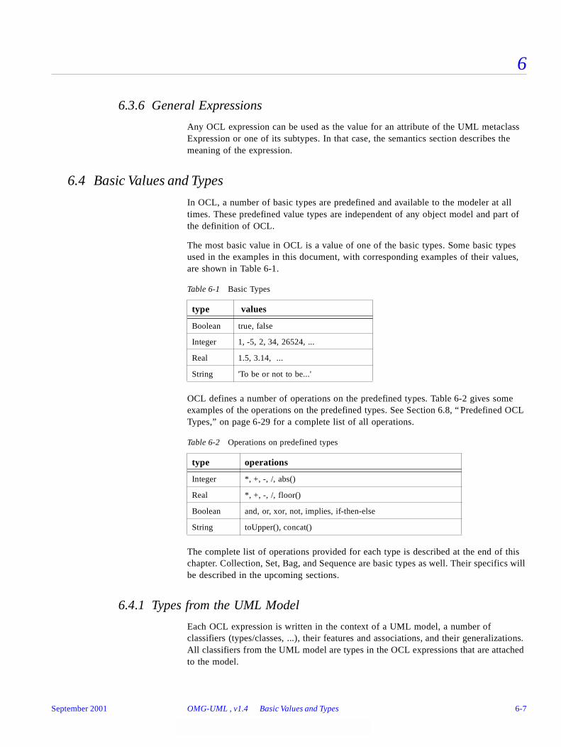
6
6.3.6 General Expressions
Any OCL expression can be used as the value for an attribute of the UML metaclass Expression or one of its subtypes. In that case, the semantics section describes the meaning of the expression.
6.4 Basic Values and Types
In OCL, a number of basic types are predefined and available to the modeler at all times. These predefined value types are independent of any object model and part of the definition of OCL.
The most basic value in OCL is a value of one of the basic types. Some basic types used in the examples in this document, with corresponding examples of their values, are shown in Table 6-1.
OCL defines a number of operations on the predefined types. Table 6-2 gives some examples of the operations on the predefined types. See Section 6.8, “ Predefined OCL Types,” on page 6-29 for a complete list of all operations.
The complete list of operations provided for each type is described at the end of this chapter. Collection, Set, Bag, and Sequence are basic types as well. Their specifics will be described in the upcoming sections.
6.4.1 Types from the UML Model
Each OCL expression is written in the context of a UML model, a number of classifiers (types/classes, ...), their features and associations, and their generalizations. All classifiers from the UML model are types in the OCL expressions that are attached to the model.
Table 6-1 Basic Types
type values
Boolean true, false
Integer 1, -5, 2, 34, 26524, ...
Real 1.5, 3.14, ...
String 'To be or not to be...'
Table 6-2 Operations on predefined types
type operations
Integer *, +, -, /, abs()
Real *, +, -, /, floor()
Boolean and, or, xor, not, implies, if-then-else
String toUpper(), concat()
September 2001 OMG-UML , v1.4 Basic Values and Types 6-7

6
6.4.2 Enumeration Types
Enumerations are Datatypes in UML and have a name, just like any other Classifier. An enumeration defines a number of enumeration literals, that are the possible values of the enumeration. Within OCL one can refer to the value of an enumeration. When we have Datatype named Sex with values ‘female’ or ‘male’ they can be used as follows:
context Person inv:
sex = Sex::male
6.4.3 Let Expressions and «definition» Constraints
Sometimes a sub-expression is used more than once in a constraint. The let expression allows one to define an attribute or operation that can be used in the constraint.
context Person inv:
let income : Integer = self.job.salary->sum()
let hasTitle(t : String) : Boolean =
self.job->exists(title = t) in
if isUnemployed then
self.income < 100
else
self.income >= 100 and self.hasTitle(‘manager’)
endif
A let expression may be included in an invariant or pre- or postcondition. It is then only known within this specific constraint. To enable reuse of let variables/operations one can use a Constraint with the stereotype «definition», in which let variables/operations are defined. This «definition» Constraint must be attached to a Classifier and may only contain let definitions. All variables and operations defined in the «definition» constraint are known in the same context as where any property of the Classifier can be used. In essence, such variables and operations are psuedo-attributes and psuedo-operations of the classifier. They are used in an OCL expression in exactly the same way as attributes or operations are used. The textual notation for a «definition» Constraint uses the keyword ‘def’ as shown below:
context Person def:
let income : Integer = self.job.salary->sum()
let hasTitle(t : String) : Boolean =
self.job->exists(title = t)
The names of the attributes / operations in a let expression may not conflict with the names of respective attributes/associationEnds and operations of the Classifier. Also, the names of all let variables and operations connected with a Classifier must be unique.
6-8 OMG-Unified Modeling Language, v1.4 September 2001
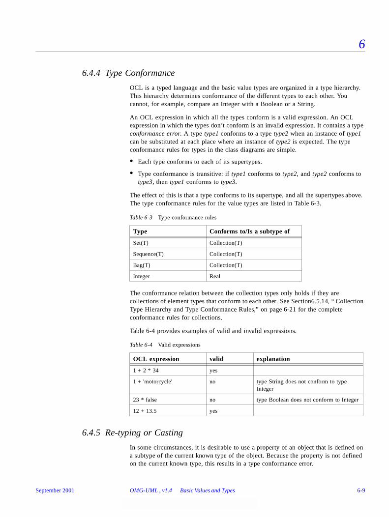
6
6.4.4 Type Conformance
OCL is a typed language and the basic value types are organized in a type hierarchy. This hierarchy determines conformance of the different types to each other. You cannot, for example, compare an Integer with a Boolean or a String.
An OCL expression in which all the types conform is a valid expression. An OCL expression in which the types don’t conform is an invalid expression. It contains a type conformance error. A type type1 conforms to a type type2 when an instance of type1 can be substituted at each place where an instance of type2 is expected. The type conformance rules for types in the class diagrams are simple.
• Each type conforms to each of its supertypes.
• Type conformance is transitive: if type1 conforms to type2, and type2 conforms to type3, then type1 conforms to type3.
The effect of this is that a type conforms to its supertype, and all the supertypes above. The type conformance rules for the value types are listed in Table 6-3.
The conformance relation between the collection types only holds if they are collections of element types that conform to each other. See Section6.5.14, “ Collection Type Hierarchy and Type Conformance Rules,” on page 6-21 for the complete conformance rules for collections.
Table 6-4 provides examples of valid and invalid expressions.
6.4.5 Re-typing or Casting
In some circumstances, it is desirable to use a property of an object that is defined on a subtype of the current known type of the object. Because the property is not defined on the current known type, this results in a type conformance error.
Table 6-3 Type conformance rules
Type Conforms to/Is a subtype of
Set(T) Collection(T)
Sequence(T) Collection(T)
Bag(T) Collection(T)
Integer Real
Table 6-4 Valid expressions
OCL expression valid explanation
1 + 2 * 34 yes
1 + 'motorcycle' no type String does not conform to type Integer
23 * false no type Boolean does not conform to Integer
12 + 13.5 yes
September 2001 OMG-UML , v1.4 Basic Values and Types 6-9
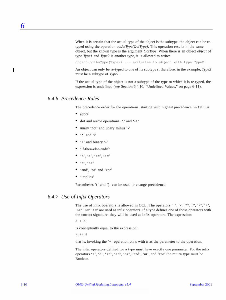
6
When it is certain that the actual type of the object is the subtype, the object can be re-typed using the operation oclAsType(OclType). This operation results in the same object, but the known type is the argument OclType. When there is an object object of type Type1 and Type2 is another type, it is allowed to write:
object.oclAsType(Type2) --- evaluates to object with type Type2
An object can only be re-typed to one of its subtype s; therefore, in the example, Type2 must be a subtype of Type1.
If the actual type of the object is not a subtype of the type to which it is re-typed, the expression is undefined (see Section 6.4.10, “Undefined Values,” on page 6-11).
6.4.6 Precedence Rules
The precedence order for the operations, starting with highest precedence, in OCL is:
• @pre
• dot and arrow operations: ‘.’ and ‘->’
• unary ‘not’ and unary minus ‘-’
• ‘*’ and ‘/’
• ‘+’ and binary ‘-’
• ‘if-then-else-endif’
• ‘<’, ‘>’, ‘<=’, ‘>=’
• ‘=’, ‘<>’
• ‘and’, ‘or’ and ‘xor’
• ‘implies’
Parentheses ‘(’ and ‘)’ can be used to change precedence.
6.4.7 Use of Infix Operators
The use of infix operators is allowed in OCL. The operators ‘+’, ‘-’, ‘*’. ‘/’, ‘<‘, ‘>’, ‘<>’ ‘<=’ ‘>=’ are used as infix operators. If a type defines one of those operators with the correct signature, they will be used as infix operators. The expression:
a + b
is conceptually equal to the expression:
a.+(b)
that is, invoking the ‘+’ operation on a with b as the parameter to the operation.
The infix operators defined for a type must have exactly one parameter. For the infix operators ‘<‘, ‘>’, ‘<=’, ‘>=’, ‘<>’, ‘and’, ‘or’, and ‘xor’ the return type must be Boolean.
6-10 OMG-Unified Modeling Language, v1.4 September 2001
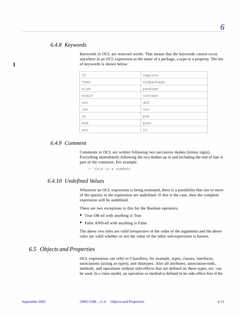
6
6.4.8 Keywords
Keywords in OCL are reserved words. That means that the keywords cannot occur anywhere in an OCL expression as the name of a package, a type or a property. The list of keywords is shown below:
6.4.9 Comment
Comments in OCL are written following two successive dashes (minus signs). Everything immediately following the two dashes up to and including the end of line is part of the comment. For example:
-- this is a comment
6.4.10 Undefined Values
Whenever an OCL expression is being evaluated, there is a possibility that one or more of the queries in the expression are undefined. If this is the case, then the complete expression will be undefined.
There are two exceptions to this for the Boolean operators:
• True OR-ed with anything is True
• False AND-ed with anything is False
The above two rules are valid irrespective of the order of the arguments and the above rules are valid whether or not the value of the other sub-expression is known.
6.5 Objects and Properties
OCL expressions can refer to Classifiers; for example, types, classes, interfaces, associations (acting as types), and datatypes. Also all attributes, association-ends, methods, and operations without side-effects that are defined on these types, etc. can be used. In a class model, an operation or method is defined to be side-effect-free if the
if implies
then endpackage
else package
endif context
not def
let inv
or pre
and post
xor in
September 2001 OMG-UML , v1.4 Objects and Properties 6-11

6
isQuery attribute of the operations is true. For the purpose of this document, we will refer to attributes, association-ends, and side-effect-free methods and operations as being properties. A property is one of:
• an Attribute
• an AssociationEnd
• an Operation with isQuery being true
• a Method with isQuery being true
6.5.1 Properties
The value of a property on an object that is defined in a class diagram is specified by a dot followed by the name of the property.
context AType inv:
self.property
If self is a reference to an object, then self.property is the value of the property property on self.
6.5.2 Properties: Attributes
For example, the age of a Person is written as self.age:
context Person inv:
self.age > 0
The value of the subexpression self.age is the value of the age attribute on the particular instance of Person identified by self. The type of this subexpression is the type of the attribute age, which is the basic type Integer.
Using attributes, and operations defined on the basic value types, we can express calculations etc. over the class model. For example, a business rule might be “the age of a Person is always greater than zero.” This can be stated as shown in the invariant above.
6.5.3 Properties: Operations
Operations may have parameters. For example, as shown earlier, a Person object has an income expressed as a function of the date. This operation would be accessed as follows, for a Person aPerson and a date aDate:
aPerson.income(aDate)
The operation itself could be defined by a postcondition constraint. This is a constraint that is stereotyped as «postcondition». The object that is returned by the operation can be referred to by result. It takes the following form:
context Person::income (d: Date) : Integer
post: result = age * 1000
6-12 OMG-Unified Modeling Language, v1.4 September 2001
6
The right-hand-side of this definition may refer to the operation being defined; that is, the definition may be recursive as long as the recursion is not infinite. The type of result is the return type of the operation, which is Integer in the above example.
To refer to an operation or a method that doesn’t take a parameter, parentheses with an empty argument list are mandatory:
context Company inv:
self.stockPrice() > 0
6.5.4 Properties: Association Ends and Navigation
Starting from a specific object, we can navigate an association on the class diagram to refer to other objects and their properties. To do so, we navigate the association by using the opposite association-end:
object.rolename
The value of this expression is the set of objects on the other side of the rolename association. If the multiplicity of the association-end has a maximum of one (“0..1” or “1”), then the value of this expression is an object. In the example class diagram, when we start in the context of a Company; that is, self is an instance of Company, we can write:
context Company
inv: self.manager.isUnemployed = false
inv: self.employee->notEmpty()
In the first invariant self.manager is a Person, because the multiplicity of the association is one. In the second invariant self.employee will evaluate in a Set of Persons. By default, navigation will result in a Set. When the association on the Class Diagram is adorned with {ordered}, the navigation results in a Sequence.
Collections, like Sets, Bags, and Sequences are predefined types in OCL. They have a large number of predefined operations on them. A property of the collection itself is accessed by using an arrow ‘->’ followed by the name of the property. The following example is in the context of a person:
context Person inv:
self.employer->size() < 3
This applies the size property on the Set self.employer, which results in the number of employers of the Person self.
context Person inv:
self.employer->isEmpty()
This applies the isEmpty property on the Set self.employer. This evaluates to true if the set of employers is empty and false otherwise.
September 2001 OMG-UML , v1.4 Objects and Properties 6-13
6
6.5.4.1 Missing Rolenames
When a rolename is missing at one of the ends of an association, the name of the type at the association end, starting with a lowercase character, is used as the rolename. If this results in an ambiguity, the rolename is mandatory. This is the case with unnamed rolenames in reflexive associations. If the rolename is ambiguous, then it cannot be used in OCL.
6.5.4.2 Navigation over Associations with Multiplicity Zero or One
Because the multiplicity of the role manager is one, self.manager is an object of type Person. Such a single object can be used as a Set as well. It then behaves as if it is a Set containing the single object. The usage as a set is done through the arrow followed by a property of Set. This is shown in the following example:
context Company inv:
self.manager->size() = 1
The sub-expression self.manager is used as a Set, because the arrow is used to access the size property on Set. This expression evaluates to true.
The following example shows how a property of a collection can be used.
context Company inv:
self.manager->foo
The sub-expression self.manager is used as Set, because the arrow is used to access the foo property on the Set. This expression is incorrect, because foo is not a defined property of Set.
context Company inv:
self.manager.age> 40
The sub-expression self.manager is used as a Person, because the dot is used to access the age property of Person.
In the case of an optional (0..1 multiplicity) association, this is especially useful to check whether there is an object or not when navigating the association. In the example we can write:
context Person inv:
self.wife->notEmpty() implies self.wife.sex = Sex::female
6.5.4.3 Combining Properties
Properties can be combined to make more complicated expressions. An important rule is that an OCL expression always evaluates to a specific object of a specific type. After obtaining a result, one can always apply another property to the result to get a new result value. Therefore, each OCL expression can be read and evaluated left-to-right.
Following are some invariants that use combined properties on the example class diagram:
6-14 OMG-Unified Modeling Language, v1.4 September 2001
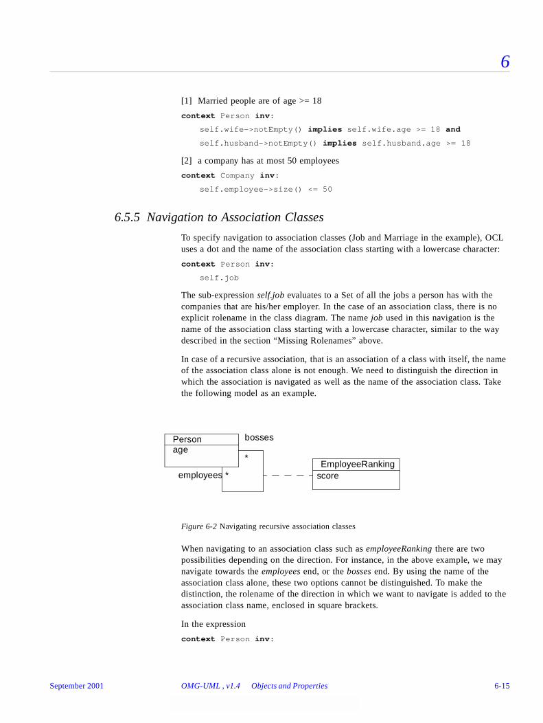
6
[1] Married people are of age >= 18
context Person inv:
self.wife->notEmpty() implies self.wife.age >= 18 and
self.husband->notEmpty() implies self.husband.age >= 18
[2] a company has at most 50 employees
context Company inv:
self.employee->size() <= 50
6.5.5 Navigation to Association Classes
To specify navigation to association classes (Job and Marriage in the example), OCL uses a dot and the name of the association class starting with a lowercase character:
context Person inv:
self.job
The sub-expression self.job evaluates to a Set of all the jobs a person has with the companies that are his/her employer. In the case of an association class, there is no explicit rolename in the class diagram. The name job used in this navigation is the name of the association class starting with a lowercase character, similar to the way described in the section “Missing Rolenames” above.
In case of a recursive association, that is an association of a class with itself, the name of the association class alone is not enough. We need to distinguish the direction in which the association is navigated as well as the name of the association class. Take the following model as an example.
Figure 6-2 Navigating recursive association classes
When navigating to an association class such as employeeRanking there are two possibilities depending on the direction. For instance, in the above example, we may navigate towards the employees end, or the bosses end. By using the name of the association class alone, these two options cannot be distinguished. To make the distinction, the rolename of the direction in which we want to navigate is added to the association class name, enclosed in square brackets.
In the expression
context Person inv:
EmployeeRanking
Personage
bosses
employees * score
*
September 2001 OMG-UML , v1.4 Objects and Properties 6-15
6
self.employeeRanking[bosses]->sum() > 0
the self.employeeRanking[bosses] evaluates to the set of EmployeeRankings belonging to the collection of bosses. And in the expression
context Person inv:
self.employeeRanking[employees]->sum() > 0
the self.employeeRanking[employees] evaluates to the set of EmployeeRankings belonging to the collection of employees. The unqualified use of the association class name is not allowed in such a recursive situation. Thus, the following example is invalid:
context Person inv:
self.employeeRanking->sum() > 0 -- INVALID!
In a non-recursive situation, the association class name alone is enough, although the qualified version is allowed as well. Therefore, the examples at the start of this section could also be written as:
context Person inv:
self.job[employer]
6.5.6 Navigation from Association Classes
We can navigate from the association class itself to the objects that participate in the association. This is done using the dot-notation and the role-names at the association-ends.
context Job
inv: self.employer.numberOfEmployees >= 1
inv: self.employee.age > 21
Navigation from an association class to one of the objects on the association will always deliver exactly one object. This is a result of the definition of AssociationClass. Therefore, the result of this navigation is exactly one object, although it can be used as a Set using the arrow (->).
6.5.7 Navigation through Qualified Associations
Qualified associations use one or more qualifier attributes to select the objects at the other end of the association. To navigate them, we can add the values for the qualifiers to the navigation. This is done using square brackets, following the role-name. It is permissible to leave out the qualifier values, in which case the result will be all objects at the other end of the association.
context Bank inv:
self.customer
This results in a Set(Person) containing all customers of the Bank.
context Bank inv:
self.customer[8764423]
6-16 OMG-Unified Modeling Language, v1.4 September 2001
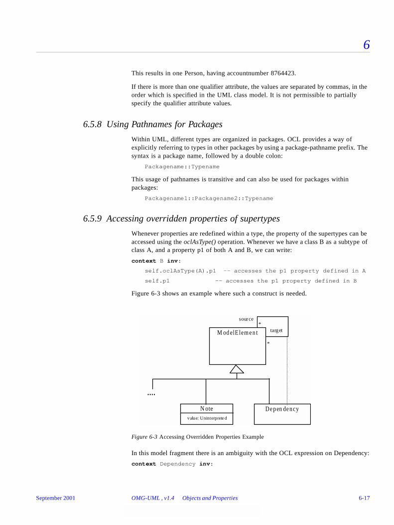
6
This results in one Person, having accountnumber 8764423.
If there is more than one qualifier attribute, the values are separated by commas, in the order which is specified in the UML class model. It is not permissible to partially specify the qualifier attribute values.
6.5.8 Using Pathnames for Packages
Within UML, different types are organized in packages. OCL provides a way of explicitly referring to types in other packages by using a package-pathname prefix. The syntax is a package name, followed by a double colon:
Packagename::Typename
This usage of pathnames is transitive and can also be used for packages within packages:
Packagename1::Packagename2::Typename
6.5.9 Accessing overridden properties of supertypes
Whenever properties are redefined within a type, the property of the supertypes can be accessed using the oclAsType() operation. Whenever we have a class B as a subtype of class A, and a property p1 of both A and B, we can write:
context B inv:
self.oclAsType(A).p1 -- accesses the p1 property defined in A
self.p1 -- accesses the p1 property defined in B
Figure 6-3 shows an example where such a construct is needed.
Figure 6-3 Accessing Overridden Properties Example
In this model fragment there is an ambiguity with the OCL expression on Dependency:
context Dependency inv:
....
De p en de n cy
target
source*
*
M od elE lem e n t
N otevalue: Uninterprete d
September 2001 OMG-UML , v1.4 Objects and Properties 6-17

6
self.source <> self
This can either mean normal association navigation, which is inherited from ModelElement, or it might also mean navigation through the dotted line as an association class. Both possible navigations use the same role-name, so this is always ambiguous. Using oclAsType() we can distinguish between them with:
context Dependency
inv: self.oclAsType(Dependency).source
inv: self.oclAsType(ModelElement).source
6.5.10 Predefined properties on All Objects
There are several properties that apply to all objects, and are predefined in OCL. These are:
oclIsTypeOf(t : OclType) : Boolean
oclIsKindOf(t : OclType) : Boolean
oclInState(s : OclState) : Boolean
oclIsNew() : Boolean
oclAsType(t : OclType) : instance of OclType
The operation is oclTypeOf results in true if the type of self and t are the same. For example:
context Person
inv: self.oclIsTypeOf( Person ) -- is true
inv: self.oclIsTypeOf( Company) -- is false
The above property deals with the direct type of an object. The oclIsKindOf property determines whether t is either the direct type or one of the supertypes of an object.
The operation oclInState(s) results in true if the object is in the state s. Values for s are the names of the states in the statemachine(s) attached to the Classifier of object. For nested states the statenames can be combined using the double colon ‘::’ .
On Off
Standby NoPower
6-18 OMG-Unified Modeling Language, v1.4 September 2001
6
In the example statemachine above, values for s can be On, Off, Off::Standby, Off::NoPower. If the classifier of object has the above associated statemachine valid OCL expressions are:
object.oclInState(On)
object.oclInState(Off)
object.oclInstate(Off::Standby)
object.oclInState(Off:NoPower)
If there are multiple statemachines attached to the object’s classifier, then the statename can be prefixed with the name of the statemachine containing the state and the double semicolon ::, as with nested states.
The operation oclIsNew evaluates to true if, used in a postcondition, the object is created during performing the operation; that is, it didn’t exist at precondition time.
6.5.11 Features on Classes Themselves
All properties discussed until now in OCL are properties on instances of classes. The types are either predefined in OCL or defined in the class model. In OCL, it is also possible to use features defined on the types/classes themselves. These are, for example, the class-scoped features defined in the class model. Furthermore, several features are predefined on each type.
A predefined feature on each type is allInstances, which results in the Set of all instances of the type in existence at the specific time when the expression is evaluated. If we want to make sure that all instances of Person have unique names, we can write:
context Person inv:
Person.allInstances->forAll(p1, p2 |
p 1 <> p2 implies p1.name <> p2.name)
The Person.allInstances is the set of all persons and is of type Set(Person). It is the set of all persons that exist at the snapshot in time that the expression is evaluated.
Note – The use of allInstances has some problems and its use is discouraged in most cases. The first problem is best explained by looking at the types like Integer, Real and String. For these types the meaning of allInstances is undefined. What does it mean for an Integer to exist? The evaluation of the expression Integer.allInstances results in an infinite set and is therefore undefined within OCL. The second problem with allInstances is that the existence of objects must be considered within some overall context, like a system or a model. This overall context must be defined, which is not done within OCL. A recommended style is to model the overall contextual system explicitly as an object within the system and navigate from that object to its containing instances without using allInstances.
September 2001 OMG-UML , v1.4 Objects and Properties 6-19
6
6.5.12 Collections
Single navigation results in a Set, combined navigations in a Bag, and navigation over associations adorned with {ordered} results in a Sequence. Therefore, the collection types play an important role in OCL expressions.
The type Collection is predefined in OCL. The Collection type defines a large number of predefined operations to enable the OCL expression author (the modeler) to manipulate collections. Consistent with the definition of OCL as an expression language, collection operations never change collections; isQuery is always true. They may result in a collection, but rather than changing the original collection they project the result into a new one.
Collection is an abstract type, with the concrete collection types as its subtypes. OCL distinguishes three different collection types: Set, Sequence, and Bag. A Set is the mathematical set. It does not contain duplicate elements. A Bag is like a set, which may contain duplicates; that is, the same element may be in a bag twice or more. A Sequence is like a Bag in which the elements are ordered. Both Bags and Sets have no order defined on them. Sets, Sequences, and Bags can be specified by a literal in OCL. Curly brackets surround the elements of the collection, elements in the collection are written within, separated by commas. The type of the collection is written before the curly brackets:
Set { 1 , 2 , 5 , 88 }
Set { 'apple' , 'orange', 'strawberry' }
A Sequence:
Sequence { 1, 3, 45, 2, 3 }
Sequence { 'ape', 'nut' }
A bag:
Bag {1 , 3 , 4, 3, 5 }
Because of the usefulness of a Sequence of consecutive Integers, there is a separate literal to create them. The elements inside the curly brackets can be replaced by an interval specification, which consists of two expressions of type Integer, Int-expr1 and Int-expr2, separated by ‘..’. This denotes all the Integers between the values of Int-expr1 and Int-expr2, including the values of Int-expr1 and Int-expr2 themselves:
Sequence{ 1..(6 + 4) }
Sequence{ 1..10 }
-- are both identical to
Sequence{ 1, 2, 3, 4, 5, 6, 7, 8, 9, 10 }
The complete list of Collection operations is described at the end of this chapter.
Collections can be specified by a literal, as described above. The only other way to get a collection is by navigation. To be more precise, the only way to get a Set, Sequence, or Bag is:
1. a literal, this will result in a Set, Sequence, or Bag:
Set {1 , 2, 3 , 5 , 7 , 11, 13, 17 }
6-20 OMG-Unified Modeling Language, v1.4 September 2001

6
Sequence {1 , 2, 3 , 5 , 7 , 11, 13, 17 }
Bag {1, 2, 3, 2, 1}
2. a navigation starting from a single object can result in a collection:
context Company inv:
self.employee
3. operations on collections may result in new collections:
collection1->union(collection2)
6.5.13 Collections of Collections
Within OCL, all Collections of Collections are flattened automatically; therefore, the following two expressions have the same value:
Set{ Set{1, 2}, Set{3, 4}, Set{5, 6} }
Set{ 1, 2, 3, 4, 5, 6 }
6.5.14 Collection Type Hierarchy and Type Conformance Rules
In addition to the type conformance rules in Section 6.4.4, “Type Conformance,” on page 6-9, the following rules hold for all types, including the collection types:
• The types Set (X), Bag (X) and Sequence (X) are all subtypes of Collection (X).
Type conformance rules are as follows for the collection types:
• Type1 conforms to Type2 when they are identical (standard rule for all types).
• Type1 conforms to Type2 when it is a subtype of Type2 (standard rule for all types).
• Collection(Type1) conforms to Collection(Type2), when Type1 conforms to Type2.
• Type conformance is transitive: if Type1 conforms to Type2, and Type2 conforms to Type3, then Type1 conforms to Type3 (standard rule for all types).
For example, if Bicycle and Car are two separate subtypes of Transport:
Set(Bicycle) conforms to Set(Transport)
Set(Bicycle) conforms to Collection(Bicycle)
Set(Bicycle) conforms to Collection(Transport)
Note that Set(Bicycle) does not conform to Bag(Bicycle), nor the other way around. They are both subtypes of Collection(Bicycle) at the same level in the hierarchy.
6.5.15 Previous Values in Postconditions
As stated in Section6.3.4, “ Pre- and Postconditions,” on page6-5, OCL can be used to specify pre- and post-conditions on operations and methods in UML. In a postcondition, the expression can refer to two sets of values for each property of an object:
• the value of a property at the start of the operation or method
September 2001 OMG-UML , v1.4 Objects and Properties 6-21
6
• the value of a property upon completion of the operation or method
The value of a property in a postcondition is the value upon completion of the operation. To refer to the value of a property at the start of the operation, one has to postfix the property name with the keyword ‘@pre’:
context Person::birthdayHappens()
post: age = age@pre + 1
The property age refers to the property of the instance of Person on which executes the operation. The property age@pre refers to the value of the property age of the Person that executes the operation, at the start of the operation.
If the property has parameters, the ‘@pre’ is postfixed to the propertyname, before the parameters.
context Company::hireEmployee(p : Person)
post: employees = employees@pre->including(p) andstockprice() = stockprice@pre() + 10
The above operation can also be specified by a postcondition and a precondition together:
context Company::hireEmployee(p : Person)
pre : not employee->includes(p)
post: employees->includes(p) and
stockprice() = stockprice@pre() + 10
When the pre-value of a property evaluates to an object, all further properties that are accessed of this object are the new values (upon completion of the operation) of this object. So:
[email protected] -- takes the old value of property b of a, say x
-- and then the new value of c of x.
[email protected]@pre -- takes the old value of property b of a, say x
-- and then the old value of c of x.
The ‘@pre’ postfix is allowed only in OCL expressions that are part of a Postcondition. Asking for a current property of an object that has been destroyed during execution of the operation results in Undefined. Also, referring to the previous value of an object that has been created during execution of the operation results in Undefined.
6.6 Collection Operations
OCL defines many operations on the collection types. These operations are specifically meant to enable a flexible and powerful way of projecting new collections from existing ones. The different constructs are described in the following sections.
6-22 OMG-Unified Modeling Language, v1.4 September 2001

6
6.6.1 Select and Reject Operations
Sometimes an expression using operations and navigations delivers a collection, while we are interested only in a special subset of the collection. OCL has special constructs to specify a selection from a specific collection. These are the select and reject operations. The select specifies a subset of a collection. A select is an operation on a collection and is specified using the arrow-syntax:
collection->select( ... )
The parameter of select has a special syntax that enables one to specify which elements of the collection we want to select. There are three different forms, of which the simplest one is:
collection->select( boolean-expression )
This results in a collection that contains all the elements from collection for which the boolean-expression evaluates to true. To find the result of this expression, for each element in collection the expression boolean-expression is evaluated. If this evaluates to true, the element is included in the result collection, otherwise not. As an example, the following OCL expression specifies that the collection of all the employees older than 50 years is not empty:
context Company inv:
self.employee->select(age > 50)->notEmpty()
The self.employee is of type Set(Person). The select takes each person from self.employee and evaluates age > 50 for this person. If this results in true, then the person is in the result Set.
As shown in the previous example, the context for the expression in the select argument is the element of the collection on which the select is invoked. Thus the age property is taken in the context of a person.
In the above example, it is impossible to refer explicitly to the persons themselves; you can only refer to properties of them. To enable to refer to the persons themselves, there is a more general syntax for the select expression:
collection->select( v | boolean-expression-with-v )
The variable v is called the iterator. When the select is evaluated, v iterates over the collection and the boolean-expression-with-v is evaluated for each v. The v is a reference to the object from the collection and can be used to refer to the objects themselves from the collection. The two examples below are identical:
context Company inv:
self.employee->select(age > 50)->notEmpty()
context Company inv:
self.employee->select(p | p.age > 50)->notEmpty()
The result of the complete select is the collection of persons p for which the p.age > 50 evaluates to True. This amounts to a subset of self.employee.
As a final extension to the select syntax, the expected type of the variable v can be given. The select now is written as:
September 2001 OMG-UML , v1.4 Collection Operations 6-23
6
collection->select( v : Type | boolean-expression-with-v )
The meaning of this is that the objects in collection must be of type Type. The next example is identical to the previous examples:
context Company inv:
self.employee.select(p : Person | p.age > 50)->notEmpty()
The compete select syntax now looks like one of:
collection->select( v : Type | boolean-expression-with-v )
collection->select( v | boolean-expression-with-v )
collection->select( boolean-expression )
The reject operation is identical to the select operation, but with reject we get the subset of all the elements of the collection for which the expression evaluates to False. The reject syntax is identical to the select syntax:
collection->reject( v : Type | boolean-expression-with-v )
collection->reject( v | boolean-expression-with-v )
collection->reject( boolean-expression )
As an example, specify that the collection of all the employees who are not married is empty:
context Company inv:
self.employee->reject( isMarried )->isEmpty()
The reject operation is available in OCL for convenience, because each reject can be restated as a select with the negated expression. Therefore, the following two expressions are identical:
collection->reject( v : Type | boolean-expression-with-v )
collection->select( v : Type | not (boolean-expression-with-v) )
6.6.2 Collect Operation
As shown in the previous section, the select and reject operations always result in a sub-collection of the original collection. When we want to specify a collection that is derived from some other collection, but which contains different objects from the original collection; that is, it is not a sub-collection, we can use a collect operation. The collect operation uses the same syntax as the select and reject and is written as one of:
collection->collect( v : Type | expression-with-v )
collection->collect( v | expression-with-v )
collection->collect( expression )
The value of the reject operation is the collection of the results of all the evaluations of expression-with-v.
An example: specify the collection of birthDates for all employees in the context of a company. This can be written in the context of a Company object as one of:
self.employee->collect( birthDate )
6-24 OMG-Unified Modeling Language, v1.4 September 2001
6
self.employee->collect( person | person.birthDate )
self.employee->collect( person : Person | person.birthDate )
An important issue here is that the resulting collection is not a Set, but a Bag. When more than one employee has the same value for birthDate, this value will be an element of the resulting Bag more than once. The Bag resulting from the collect operation always has the same size as the original collection.
It is possible to make a Set from the Bag, by using the asSet property on the Bag. The following expression results in the Set of different birthDates from all employees of a Company:
self.employee->collect( birthDate )->asSet()
6.6.2.1 Shorthand for Collect
Because navigation through many objects is very common, there is a shorthand notation for the collect that makes the OCL expressions more readable. Instead of
self.employee->collect(birthdate)
we can also write:
self.employee.birthdate
In general, when we apply a property to a collection of Objects, then it will automatically be interpreted as a collect over the members of the collection with the specified property.
For any propertyname that is defined as a property on the objects in a collection, the following two expressions are identical:
collection.propertyname
collection->collect(propertyname)
and so are these if the property is parameterized:
collection.propertyname(par1, par2, ...)
collection->collect(propertyname(par1, par2, ...)
6.6.3 ForAll Operation
Many times a constraint is needed on all elements of a collection. The forAll operation in OCL allows specifying a Boolean expression, which must hold for all objects in a collection:
collection->forAll( v : Type | boolean-expression-with-v )
collection->forAll( v | boolean-expression-with-v )
collection->forAll( boolean-expression )
This forAll expression results in a Boolean. The result is true if the boolean-expression-with-v is true for all elements of collection. If the boolean-expression-with-v is false for one or more v in collection, then the complete expression evaluates to false. For example, in the context of a company:
September 2001 OMG-UML , v1.4 Collection Operations 6-25
6
context Company
inv: self.employee->forAll( forename = 'Jack' )
inv: self.employee->forAll( p | p.forename = 'Jack' )
inv: self.employee->forAll( p : Person | p.forename = 'Jack' )
These invariants evaluate to true if the forename feature of each employee is equal to ‘Jack.’
The forAll operation has an extended variant in which more then one iterator is used. Both iterators will iterate over the complete collection. Effectively this is a forAll on the Cartesian product of the collection with itself.
context Company inv:
self.employee->forAll( e1, e2 |
e1 <> e2 implies e1.forename <> e2.forename)
context Company inv:
self.employee->forAll( e1, e2 : Person |
e1 <> e2 implies e1.forename <> e2.forename)
This expression evaluates to true if the forenames of all employees are different. It is semantically equivalent to:
context Company inv:
self.employee->forAll(e1 | self.employee->forAll (e2 |
e1 <> e2 implies e1.forename <> e2.forename)))
6.6.4 Exists Operation
Many times one needs to know whether there is at least one element in a collection for which a constraint holds. The exists operation in OCL allows you to specify a Boolean expression that must hold for at least one object in a collection:
collection->exists( v : Type | boolean-expression-with-v )
collection->exists( v | boolean-expression-with-v )
collection->exists( boolean-expression )
This exists operation results in a Boolean. The result is true if the boolean-expression-with-v is true for at least one element of collection. If the boolean-expression-with-v is false for all v in collection, then the complete expression evaluates to false. For example, in the context of a company:
context Company inv:
self.employee->exists( forename = 'Jack' )
context Company inv:
self.employee->exists( p | p.forename = 'Jack' )
context Company inv:
self.employee->exists( p : Person | p.forename = 'Jack' )
These expressions evaluate to true if the forename feature of at least one employee is equal to ‘Jack.’
6-26 OMG-Unified Modeling Language, v1.4 September 2001
6
6.6.5 Iterate Operation
The iterate operation is slightly more complicated, but is very generic. The operations reject, select, forAll, exists, collect can all be described in terms of iterate.
An accumulation builds one value by iterating over a collection.
collection->iterate( elem : Type; acc : Type = <expression> |
expression-with-elem-and-acc )
The variable elem is the iterator, as in the definition of select, forAll, etc. The variable acc is the accumulator. The accumulator gets an initial value <expression>.
When the iterate is evaluated, elem iterates over the collection and the expression-with-elem-and-acc is evaluated for each elem. After each evaluation of expression-with-elem-and-acc, its value is assigned to acc. In this way, the value of acc is built up during the iteration of the collection. The collect operation described in terms of iterate will look like:
collection->collect(x : T | x.property)
-- is identical to:
collection->iterate(x : T; acc : T2 = Bag{} |
acc->including(x.property))
Or written in Java-like pseudocode the result of the iterate can be calculated as:
iterate(elem : T; acc : T2 = value)
{
acc = value;
for(Enumeration e = collection.elements() ; e.hasMoreElements(); ){
elem = e.nextElement();
acc = <expression-with-elem-and-acc>
}
}
Although the Java pseudo code uses a ‘next element,’ the iterate operation is defined for each collection type and the order of the iteration through the elements in the collection is not defined for Set and Bag. For a Sequence the order is the order of the elements in the sequence.
6.6.6 Iterators in Collection Operations
The collection operations that take an OclExpression as parameter may all have an optional iterator declaration. For any operation name op, the syntax options are:
collection->op( iter : Type | OclExpression )
collection->op( iter | OclExpression )
collection->op( OclExpression )
September 2001 OMG-UML , v1.4 Collection Operations 6-27
6
6.6.7 Resolving Properties
For any property (attribute, operation, or navigation), the full notation includes the object of which the property is taken. As seen in Section 6.3.3, “Invariants,” on page 6-5, self can be left implicit, and so can the iterator variables in collection operations. At any place in an expression, when an iterator is left out, an implicit iterator-variable is introduced. For example in:
context Person inv:
employer->forAll( employee->exists( lastName = name) )
three implicit variables are introduced. The first is self, which is always the instance from which the constraint starts. Secondly an implicit iterator is introduced by the forAll and third by the exists. The implicit iterator variables are unnamed. The properties employer, employee, lastName and name all have the object on which they are applied left out. Resolving these goes as follows:
• At the place of employer there is one implicit variable: self : Person. Therefore employer must be a property of self.
• At the place of employee there are two implicit variables: self : Person and iter1 : Company. Therefore employer must be a property of either self or iter1. If employee is a property of both self and iter1, then this is unambiguous and the instance on which employee is applied must be stated explicitly. In this case only iter1.employee is possible.
• At the place of lastName and name there are three implicit variables: self : Person , iter1 : Company and iter2 : Person. Therefore lastName and name must both be a property of either self or iter1 or iter2. Property name is a property of iter1. However, lastName is a property of both self and iter2. This is ambiguous and therefore the OCL expression is incorrect. The expression must state either self.lastName or define the iter2 iterator variable explicit and state iter2.lastName.
Both of the following invariant constraints are correct:
context Person
inv: employer->forAll( employee->exists( p | p.lastName = name) )
inv: employer->forAll( employee->exists( self.lastName = name) )
6.7 The Standard OCL Package
Each UML model that uses OCL constraints contains a predefined standard package called “UML_OCL.” This package is used by default in all other packages in the model to evaluate OCL expressions. This package contains all predefined OCL types and their features.
To extend the predefined OCL types, a modeler should define a separate package. The standard OCL package can be imported, and each OCL type can be extended with new features.
6-28 OMG-Unified Modeling Language, v1.4 September 2001
6
To specify that a package used the predefined OCL types from a user defined package instead of the standard package, the using package must define a Dependency with stereotype «OCL_Types» to the package that defines the extended OCL types.
A constraint on the user defined OCL package is that as a minimum all predefined OCL types with all of their features must be defined. The user defined package must be a proper extension to the standard OCL package.
6.8 Predefined OCL Types
This section contains all standard types defined within OCL, including all the properties defined on those types. Its signature and a description of its semantics define each property. Within the description, the reserved word ‘result’ is used to refer to the value that results from evaluating the property. In several places, post conditions are used to describe properties of the result. When there is more than one postcondition, all postconditions must be true.
6.8.1 Basic Types
The basic types used are Integer, Real, String, and Boolean. They are supplemented with OclExpression, OclType, and OclAny.
6.8.1.1 OclType
All types defined in a UML model, or pre-defined within OCL, have a type. This type is an instance of the OCL type called OclType. Access to this type allows the modeler limited access to the meta-level of the model. This can be useful for advanced modelers.
Properties of OclType, where the instance of OclType is called type.
type.name() : String
The name of type.
type.attributes() : Set(String)
The set of names of the attributes of type, as they are defined in the model.
type.associationEnds() : Set(String)
The set of names of the navigable associationEnds of type, as they are defined in the model.
type.operations() : Set(String)
The set of names of the operations of type, as they are defined in the model.
September 2001 OMG-UML , v1.4 Predefined OCL Types 6-29
6
6.8.1.2 OclAny
Within the OCL context, the type OclAny is the supertype of all types in the model and the basic predefined OCL type. The predefined OCL Collection types are not subtypes of OclAny. Properties of OclAny are available on each object in all OCL expressions.
All classes in a UML model inherit all properties defined on OclAny. To avoid name conflicts between properties in the model and the properties inherited from OclAny, all names on the properties of OclAny start with ‘ocl.’ Although theoretically there may still be name conflicts, they can be avoided. One can also use the oclAsType() operation to explicitly refer to the OclAny properties.
Properties of OclAny, where the instance of OclAny is called object.
type.supertypes() : Set(OclType)
The set of all direct supertypes of type.post: type.allSupertypes()->includesAll(result)
type.allSupertypes() : Set(OclType)
The transitive closure of the set of all supertypes of type.
type.allInstances() : Set(type)
The set of all instances of type and all its subtypes in existence at the snapshot at the time that the expression is evaluated.
object = (object2 : OclAny) : Boolean
True if object is the same object as object2.
object <> (object2 : OclAny) : Boolean
True if object is a different object from object2.post: result = not (object = object2)
object.oclIsKindOf(type : OclType) : Boolean
True if type is one of the types of object, or one of the supertypes (transitive) of the types of object.
object.oclIsTypeOf(type : OclType) : Boolean
True if type is equal to one of the types of object.
object.oclAsType(type : OclType) : type
Results in object, but of known type type.Results in Undefined if the actual type of object is not type or one of its subtypes.pre : object.oclIsKindOf(type)post: result = objectpost: result.oclIsKindOf(type)
6-30 OMG-Unified Modeling Language, v1.4 September 2001
6
6.8.1.3
6.8.1.4
6.8.1.5 OclState
The type OclState is used as a parameter for the operation oclInState. There are no properties defined on OclState. One can only specify an OclState by using the name of the state, as it appears in a statemachine. These names can be fully qualified by the nested states and statemachine that contain them.
6.8.1.6 OclExpression
Each OCL expression itself is an object in the context of OCL. The type of the expression is OclExpression. This type and its properties are used to define the semantics of properties that take an expression as one of their parameters: select, collect, forAll, etc.
An OclExpression includes the optional iterator variable and type and the optional accumulator variable and type.
Properties of OclExpression, where the instance of OclExpression is called expression.
6.8.1.7 Real
The OCL type Real represents the mathematical concept of real. Note that Integer is a subclass of Real, so for each parameter of type Real, you can use an integer as the actual parameter.
Properties of Real, where the instance of Real is called r.
object.oclInState(state : OclState) : Boolean
Results in true if object is in the state state, otherwise results in false. The argument is a name of a state in the state machine corresponding with the class of object.
object.oclIsNew() : Boolean
Can only be used in a postcondition.Evaluates to true if the object is created during performing the operation. That is it didn’t exist at precondition time.
expression.evaluationType() : OclType
The type of the object that results from evaluating expression.
r = (r2 : Real) : Boolean
True if r is equal to r2.
September 2001 OMG-UML , v1.4 Predefined OCL Types 6-31
6
r <> (r2 : Real) : Boolean
True if r is not equal to r2.post: result = not (r = r2)
r + (r2 : Real) : Real
The value of the addition of r and r2.
r - (r2 : Real) : Real
The value of the subtraction of r2 from r.
r * (r2 : Real) : Real
The value of the multiplication of r and r2.
- r : Real
The negative value of r.
r / (r2 : Real) : Real
The value of r divided by r2.
r.abs() : Real
The absolute value of r.post: if r < 0 then result = - r else result = r endif
r.floor() : Integer
The largest integer which is less than or equal to r.post: (result <= r) and (result + 1 > r)
r.round() : Integer
The integer that is closest to r. When there are two such integers, the largest one.post: ((r - result) < r).abs() < 0.5) or ((r - result).abs() = 0.5 and (result > r))
r.max(r2 : Real) : Real
The maximum of r and r2.post: if r >= r2 then result = r else result = r2 endif
r.min(r2 : Real) : Real
The minimum of r and r2.post: if r <= r2 then result = r else result = r2 endif
r < (r2 : Real) : Boolean
True if r1 is less than r2.
6-32 OMG-Unified Modeling Language, v1.4 September 2001

6
6.8.1.8 Integer
The OCL type Integer represents the mathematical concept of integer.
Properties of Integer, where the instance of Integer is called i.
r > (r2 : Real) : Boolean
True if r1 is greater than r2.post: result = not (r <= r2)
r <= (r2 : Real) : Boolean
True if r1 is less than or equal to r2.post: result = (r = r2) or (r < r2)
r >= (r2 : Real) : Boolean
True if r1 is greater than or equal to r2.post: result = (r = r2) or (r > r2)
i = (i2 : Integer) : Boolean
True if i is equal to i2.
- i : Integer
The negative value of i.
i + (i2 : Integer) : Integer
The value of the addition of i and i2.
i - (i2 : Integer) : Integer
The value of the subtraction of i2 from i.
i * (i2 : Integer) : Integer
The value of the multiplication of i and i2.
i / (i2 : Integer) : Real
The value of i divided by i2.
i.abs() : Integer
The absolute value of i.post: if i < 0 then result = - i else result = i endif
September 2001 OMG-UML , v1.4 Predefined OCL Types 6-33

6
6.8.1.9 String
The OCL type String represents ASCII strings.
Properties of String, where the instance of String is called string.
i.div( i2 : Integer) : Integer
The number of times that i2 fits completely within i.pre : i2 <> 0post: if i / i2 >= 0 then result = (i / i2).floor() else result = -((-i/i2).floor()) endif
i.mod( i2 : Integer) : Integer
The result is i modulo i2.post: result = i - (i.div(i2) * i2)
i.max(i2 : Integer) : Integer
The maximum of i an i2.post: if i >= i2 then result = i else result = i2 endif
i.min(i2 : Integer) : Integer
The minimum of i an i2.post: if i <= i2 then result = i else result = i2 endif
string = (string2 : String) : Boolean
True if string and string2 contain the same characters, in the same order.
string.size() : Integer
The number of characters in string.
string.concat(string2 : String) : String
The concatenation of string and string2.post: result.size() = string.size() + string2.size()post: result.substring(1, string.size() ) = stringpost: result.substring(string.size() + 1, result.size() ) = string2
string.toUpper() : String
The value of string with all lowercase characters converted to uppercase characters.post: result.size() = string.size()
string.toLower() : String
The value of string with all uppercase characters converted to lowercase characters.post: result.size() = string.size()
6-34 OMG-Unified Modeling Language, v1.4 September 2001
6
6.8.1.10 Boolean
The OCL type Boolean represents the common true/false values.
Features of Boolean, the instance of Boolean is called b.
6.8.1.11 Enumeration
The OCL type Enumeration represents the enumerations defined in a UML model.
string.substring(lower : Integer, upper : Integer) : String
The sub-string of string starting at character number lower, up to and including character number upper.
b = (b2 : Boolean) : Boolean
Equal if b is the same as b2.
b or (b2 : Boolean) : Boolean
True if either b or b2 is true.
b xor (b2 : Boolean) : Boolean
True if either b or b2 is true, but not both.post: (b or b2) and not (b = b2)
b and (b2 : Boolean) : Boolean
True if both b1 and b2 are true.
not b : Boolean
True if b is false.post: if b then result = false else result = true endif
b implies (b2 : Boolean) : Boolean
True if b is false, or if b is true and b2 is true.post: (not b) or (b and b2)
if b then (expression1 : OclExpression)
else (expression2 : OclExpression) endif : expression1.evaluationType()
If b is true, the result is the value of evaluating expression1; otherwise, result is the value of evaluating expression2.
September 2001 OMG-UML , v1.4 Predefined OCL Types 6-35
6
Features of Enumeration, the instance of Enumeration is called enumeration.
6.8.2 Collection-Related Types
The following sections define the properties on collections; that is, these properties are available on Set, Bag, and Sequence. As defined in this section, each collection type is actually a template with one parameter. ‘T’ denotes the parameter. A real collection type is created by substituting a type for the T. So Set (Integer) and Bag (Person) are collection types.
All collection operations with an OclExpression as parameter can have an iterator declarator.
6.8.2.1 Collection
Collection is the abstract supertype of all collection types in OCL. Each occurrence of an object in a collection is called an element. If an object occurs twice in a collection, there are two elements. This section defines the properties on Collections that have identical semantics for all collection subtypes. Some properties may be defined with the subtype as well, which means that there is an additional postcondition or a more specialized return value.
The definition of several common properties is different for each subtype. These properties are not mentioned in this section.
Properties of Collection, where the instance of Collection is called collection.
enumeration = (enumeration2 : Boolean) : Boolean
Equal if enumeration is the same as enumeration2.
enumeration <> (enumeration2 : Boolean) : Boolean
Equal if enumeration is not the same as enumeration2.post: result = not ( enumeration = enumeration2)
collection->size() : Integer
The number of elements in the collection collection.post: result = collection->iterate(elem; acc : Integer = 0 | acc + 1)
collection->includes(object : OclAny) : Boolean
True if object is an element of collection, false otherwise.post: result = (collection->count(object) > 0)
collection->excludes(object : OclAny) : Boolean
True if object is not an element of collection, false otherwise.post: result = (collection->count(object) = 0)
6-36 OMG-Unified Modeling Language, v1.4 September 2001
6
collection->count(object : OclAny) : Integer
The number of times that object occurs in the collection collection.post: result = collection->iterate( elem; acc : Integer = 0 | if elem = object then acc + 1 else acc endif)
collection->includesAll(c2 : Collection(T)) : Boolean
Does collection contain all the elements of c2 ?post: result = c2->forAll(elem | collection->includes(elem))
collection->excludesAll(c2 : Collection(T)) : Boolean
Does collection contain none of the elements of c2 ?post: result = c2->forAll(elem | collection->excludes(elem))
collection->isEmpty() : Boolean
Is collection the empty collection?post: result = ( collection->size() = 0 )
collection->notEmpty() : Boolean
Is collection not the empty collection?post: result = ( collection->size() <> 0 )
collection->sum() : T
The addition of all elements in collection. Elements must be of a type supporting the + operation. The + operation must take one parameter of type T and be both associative: (a+b)+c = a+(b+c), and commutative: a+b = b+a. Integer and Real fulfill this condition.
post: result = collection->iterate( elem; acc : T = 0 | acc + elem )
collection->exists(expr : OclExpression) : Boolean
Results in true if expr evaluates to true for at least one element in collection.
post: result = collection->iterate(elem; acc : Boolean = false | acc or expr)
collection->forAll(expr : OclExpression) : Boolean
Results in true if expr evaluates to true for each element in collection; otherwise, result is false.
post: result = collection->iterate(elem; acc : Boolean = true | acc and expr)
September 2001 OMG-UML , v1.4 Predefined OCL Types 6-37
6
6.8.2.2 Set
The Set is the mathematical set. It contains elements without duplicates. Features of Set, the instance of Set is called set.
collection->isUnique(expr : OclExpression) : Boolean
Results in true if expr evaluates to a different value for each element in collection; otherwise, result is false.
post: let values = collection->collect(expr) inresult = res->forAll(e | values->count(e) = 1)
collection->sortedBy(expr : OclExpression) : Sequence(T)
Results in the Sequence containing all elements of collection. The element for which expr has the lowest value comes first, and so on. The type of the expr expression must have the < operation defined. The < operation must return a Boolean value and must be transitive (i.e., if a < b and b < c, then a < c).
pre: expr.evaluationType().operations()->includes(‘<‘)post: result->includesAll(collection) and collection->includesAll(result)
collection->iterate(expr : OclExpression) : expr.evaluationType()
Iterates over the collection. See Section 6.6.5, “Iterate Operation,” on page 6-27 for a complete description. This is the basic collection operation with which the other collection operations can be described.
collection->any(expr : OclExpression) : T
Returns any element in the collection for which expr evaluates to true. If there is more than one element for which expr is true, one of them is returned. The precondition states that there must be at least one element fulfilling expr; otherwise, the result of this operation is Undefined.
pre: collection->exists( expr )post collection->select(expr)->includes(result)
collection->one(expr : OclExpression) : Boolean
Results in true if there is exactly one element in the collection for which expr is true.post: collection->select(expr)->size() = 1
set->union(set2 : Set(T)) : Set(T)
The union of set and set2.
post: result->forAll(elem | set->includes(elem) or set2->includes(elem))post: set->forAll(elem | result->includes(elem))post: set2->forAll(elem | result->includes(elem))
6-38 OMG-Unified Modeling Language, v1.4 September 2001

6
set->union(bag : Bag(T)) : Bag(T)
The union of set and bag.
post: result->forAll(elem | result->count(elem) = set->count(elem) + bag->count(elem))
post: set->forAll(elem | result->includes(elem))post: bag->forAll(elem | result->includes(elem))
set = (set2 : Set(T)) : Boolean
Evaluates to true if set and set2 contain the same elements.
post: result = (set->forAll(elem | set2->includes(elem)) and set2->forAll(elem | set->includes(elem)) )
set->intersection(set2 : Set(T)) : Set(T)
The intersection of set and set2; that is, the set of all elements that are in both set and set2.
post: result->forAll(elem | set->includes(elem) and set2->includes(elem))post: set->forAll(elem | set2->includes(elem) = result->includes(elem))post: set2->forAll(elem | set->includes(elem) = result->includes(elem))
set->intersection(bag : Bag(T)) : Set(T)
The intersection of set and bag.post: result = set->intersection( bag->asSet )
set – (set2 : Set(T)) : Set(T)
The elements of set, which are not in set2.
post: result->forAll(elem | set->includes(elem) and set2->excludes(elem))post: set->forAll(elem | result->includes(elem) = set2->excludes(elem))
set->including(object : T) : Set(T)
The set containing all elements of set plus object.
post: result->forAll(elem | set->includes(elem) or (elem = object))post: set->forAll(elem | result->includes(elem))post: result->includes(object)
set->excluding(object : T) : Set(T)
The set containing all elements of set without object.
post: result->forAll(elem | set->includes(elem) and (elem <> object))post: set->forAll(elem | result->includes(elem) = (object <> elem))post: result->excludes(object)
September 2001 OMG-UML , v1.4 Predefined OCL Types 6-39
6
6.8.2.3 Bag
A bag is a collection with duplicates allowed. That is, one object can be an element of a bag many times. There is no ordering defined on the elements in a bag.
set->symmetricDifference(set2 : Set(T)) : Set(T)
The sets containing all the elements that are in set or set2, but not in both.
post: result->forAll(elem | set->includes(elem) xor set2->includes(elem))post: set->forAll(elem | result->includes(elem) = set2->excludes(elem))post: set2->forAll(elem | result->includes(elem) = set->excludes(elem))
set->select(expr : OclExpression) : Set(T)
The subset of set for which expr is true.
post: result = set->iterate(elem; acc : Set(T) = Set{} | if expr then acc->including(elem) else acc endif)
set->reject(expr : OclExpression) : Set(T)
The subset of set for which expr is false.post: result = set->select(not expr)
set->collect(expr : OclExpression) : Bag(expr.evaluationType() )
The Bag of elements that results from applying expr to every member of set.
post: result = set->iterate(elem; acc : Bag(expr.evaluationType() ) = Bag{} | acc->including(expr) )
set->count(object : T) : Integer
The number of occurrences of object in set.post: result <= 1
set->asSequence() : Sequence(T)
A Sequence that contains all the elements from set, in undefined order.
post: result->forAll(elem | set->includes(elem))post: set->forAll(elem | result->count(elem) = 1)
set->asBag() : Bag(T)
The Bag that contains all the elements from set.
post: result->forAll(elem | set->includes(elem))post: set->forAll(elem | result->count(elem) = 1)
6-40 OMG-Unified Modeling Language, v1.4 September 2001
6
Properties of Bag, where the instance of Bag is called bag.
bag = (bag2 : Bag(T)) : Boolean
True if bag and bag2 contain the same elements, the same number of times.
post: result = (bag->forAll(elem | bag->count(elem) = bag2->count(elem)) and bag2->forAll(elem | bag2->count(elem) = bag->count(elem)) )
bag->union(bag2 : Bag(T)) : Bag(T)
The union of bag and bag2.
post: result->forAll( elem | result->count(elem) = bag->count(elem) + bag2->count(elem))
post: bag->forAll( elem | result->count(elem) = bag->count(elem) + bag2->count(elem))
post: bag2->forAll( elem | result->count(elem) = bag->count(elem) + bag2->count(elem))
bag->union(set : Set(T)) : Bag(T)
The union of bag and set.
post: result->forAll(elem | result->count(elem) = bag->count(elem) + set->count(elem))
post: bag->forAll(elem |result->count(elem) = bag->count(elem) + set->count(elem))
post: set->forAll(elem |result->count(elem) = bag->count(elem) + set->count(elem))
bag->intersection(bag2 : Bag(T)) : Bag(T)
The intersection of bag and bag2.
post: result->forAll(elem | result->count(elem) = bag->count(elem).min(bag2->count(elem)) )
post: bag->forAll(elem |result->count(elem) = bag->count(elem).min(bag2->count(elem)) )
post: bag2->forAll(elem |result->count(elem) = bag->count(elem).min(bag2->count(elem)) )
bag->intersection(set : Set(T)) : Set(T)
The intersection of bag and set.
post: result->forAll(elem | result->count(elem) = bag->count(elem).min(set->count(elem)) )
post: bag->forAll(elem |result->count(elem) = bag->count(elem).min(set->count(elem)) )
post: set->forAll(elem |result->count(elem) = bag->count(elem).min(set->count(elem)) )
September 2001 OMG-UML , v1.4 Predefined OCL Types 6-41
6
bag->including(object : T) : Bag(T)
The bag containing all elements of bag plus object.
post: result->forAll(elem | if elem = object then result->count(elem) = bag->count(elem) + 1 else result->count(elem) = bag->count(elem) endif)post: bag->forAll(elem | if elem = object then result->count(elem) = bag->count(elem) + 1 else result->count(elem) = bag->count(elem) endif)
bag->excluding(object : T) : Bag(T)
The bag containing all elements of bag apart from all occurrences of object.
post: result->forAll(elem | if elem = object then result->count(elem) = 0 else result->count(elem) = bag->count(elem) endif)post: bag->forAll(elem | if elem = object then result->count(elem) = 0 else result->count(elem) = bag->count(elem) endif)
bag->select(expr : OclExpression) : Bag(T)
The sub-bag of bag for which expr is true.
post: result = bag->iterate(elem; acc : Bag(T) = Bag{} | if expr then acc->including(elem) else acc endif)
bag->reject(expr : OclExpression) : Bag(T)
The sub-bag of bag for which expr is false.post: result = bag->select(not expr)
bag->collect(expr: OclExpression) : Bag(expr.evaluationType() )
The Bag of elements that results from applying expr to every member of bag.
post: result = bag->iterate(elem; acc : Bag(expr.evaluationType() ) = Bag{} | acc->including(expr) )
6-42 OMG-Unified Modeling Language, v1.4 September 2001

6
6.8.2.4 Sequence
A sequence is a collection where the elements are ordered. An element may be part of a sequence more than once.
Properties of Sequence(T), where the instance of Sequence is called sequence.
bag->count(object : T) : Integer
The number of occurrences of object in bag.
bag->asSequence() : Sequence(T)
A Sequence that contains all the elements from bag, in undefined order.
post: result->forAll(elem | bag->count(elem) = result->count(elem))post: bag->forAll(elem | bag->count(elem) = result->count(elem))
bag->asSet() : Set(T)
The Set containing all the elements from bag, with duplicates removed.
post: result->forAll(elem | bag->includes(elem) )post: bag->forAll(elem | result->includes(elem))
sequence->count(object : T) : Integer
The number of occurrences of object in sequence.
sequence = (sequence2 : Sequence(T)) : Boolean
True if sequence contains the same elements as sequence2 in the same order.
post: result = Sequence{1..sequence->size()}->forAll(index : Integer | sequence->at(index) = sequence2->at(index)) and sequence->size() = sequence2->size()
sequence->union (sequence2 : Sequence(T)) : Sequence(T)
The sequence consisting of all elements in sequence, followed by all elements in sequence2.
post: result->size() = sequence->size() + sequence2->size()post: Sequence{1..sequence->size()}->forAll(index : Integer | sequence->at(index) = result->at(index))post: Sequence{1..sequence2->size()}->forAll(index : Integer | sequence2->at(index) = result->at(index + sequence->size() )))
September 2001 OMG-UML , v1.4 Predefined OCL Types 6-43
6
sequence->append (object: T) : Sequence(T)
The sequence of elements, consisting of all elements of sequence, followed by object.
post: result->size() = sequence->size() + 1post: result->at(result->size() ) = objectpost: Sequence{1..sequence->size() }->forAll(index : Integer | result->at(index) = sequence ->at(index))
sequence->prepend(object : T) : Sequence(T)
The sequence consisting of object, followed by all elements in sequence.
post: result->size = sequence->size() + 1post: result->at(1) = objectpost: Sequence{1..sequence->size()}->forAll(index : Integer | sequence->at(index) = result->at(index + 1))
sequence->subSequence(lower : Integer, upper : Integer) : Sequence(T)
The sub-sequence of sequence starting at number lower, up to and including element number upper.
pre : 1 <= lowerpre : lower <= upperpre : upper <= sequence->size()post: result->size() = upper -lower + 1post: Sequence{lower..upper}->forAll( index | result->at(index - lower + 1) = sequence->at(index))endif
sequence->at(i : Integer) : T
The i-th element of sequence.pre : i >= 1 and i <= sequence->size()
sequence->first() : T
The first element in sequence.post: result = sequence->at(1)
sequence->last() : T
The last element in sequence.post: result = sequence->at(sequence->size() )
sequence->including(object : T) : Sequence(T)
The sequence containing all elements of sequence plus object added as the last element.post: result = sequence.append(object)
6-44 OMG-Unified Modeling Language, v1.4 September 2001
6
6.9 Grammar
This section describes the grammar for OCL expressions. An executable LL(1) version of this grammar is available on the OCL web site. (See http://www.software.ibm.com/ad/ocl).
sequence->excluding(object : T) : Sequence(T)
The sequence containing all elements of sequence apart from all occurrences of object.The order of the remaining elements is not changed.
post:result->includes(object) = falsepost: result->size() = sequence->size() - sequence->count(object)post: result = sequence->iterate(elem; acc : Sequence(T) = Sequence{}| if elem = object then acc else acc->append(elem) endif )
sequence->select(expression : OclExpression) : Sequence(T)
The subsequence of sequence for which expression is true.
post: result = sequence->iterate(elem; acc : Sequence(T) = Sequence{} | if expr then acc->including(elem) else acc endif)
sequence->reject(expression : OclExpression) : Sequence(T)
The subsequence of sequence for which expression is false.post: result = sequence->select(not expr)
sequence->collect(expression : OclExpression) : Sequence(expression.evaluationType() )
The Sequence of elements that results from applying expression to every member of sequence.
sequence->iterate(expr : OclExpression) : expr.evaluationType()
Iterates over the sequence. Iteration will be done from element at position 1 up until the element at the last position following the order of the sequence.
sequence->asBag() : Bag(T)
The Bag containing all the elements from sequence, including duplicates.
post: result->forAll(elem | sequence->count(elem) = result->count(elem) )post: sequence->forAll(elem | sequence->count(elem) = result->count(elem) )
sequence->asSet() : Set(T)
The Set containing all the elements from sequence, with duplicated removed.
post: result->forAll(elem | sequence->includes(elem))post: sequence->forAll(elem | result->includes(elem))
September 2001 OMG-UML , v1.4 Grammar 6-45

6
The grammar description uses the EBNF syntax, where “|” means a choice, “?” optionality, and “*” means zero or more times, “+” means one or more times, and expressions delimited with “/*” and “*/” are definitions described with English words or sentences. In the description of string, the syntax for lexical tokens from the JavaCC parser generator is used.
oclFile := ( "package" packageName
oclExpressions
"endpackage"
)+
packageName := pathName
oclExpressions := ( constraint )*
constraint := contextDeclaration
( ( "def" name? ":" letExpression* )
|
( stereotype name? ":" oclExpression)
)+
contextDeclaration := "context"
( operationContext | classifierContext )
classifierContext := ( name ":" name )
| name
operationContext := name "::" operationName
"(" formalParameterList ")"
( ":" returnType )?
stereotype := ( "pre" | "post" | "inv" )
operationName := name | "=" | "+" | "-" | "<" | "<=" |
">=" | ">" | "/" | "*" | "<>" |
"implies" | "not" | "or" | "xor" | "and"
formalParameterList := ( name ":" typeSpecifier
("," name ":" typeSpecifier )*
)?
typeSpecifier := simpleTypeSpecifier
| collectionType
collectionType := collectionKind
"(" simpleTypeSpecifier ")"
oclExpression := (letExpression* "in")? expression
returnType := typeSpecifier
expression := logicalExpression
letExpression := "let" name
( "(" formalParameterList ")" )?
( ":" typeSpecifier )?
"=" expression
6-46 OMG-Unified Modeling Language, v1.4 September 2001
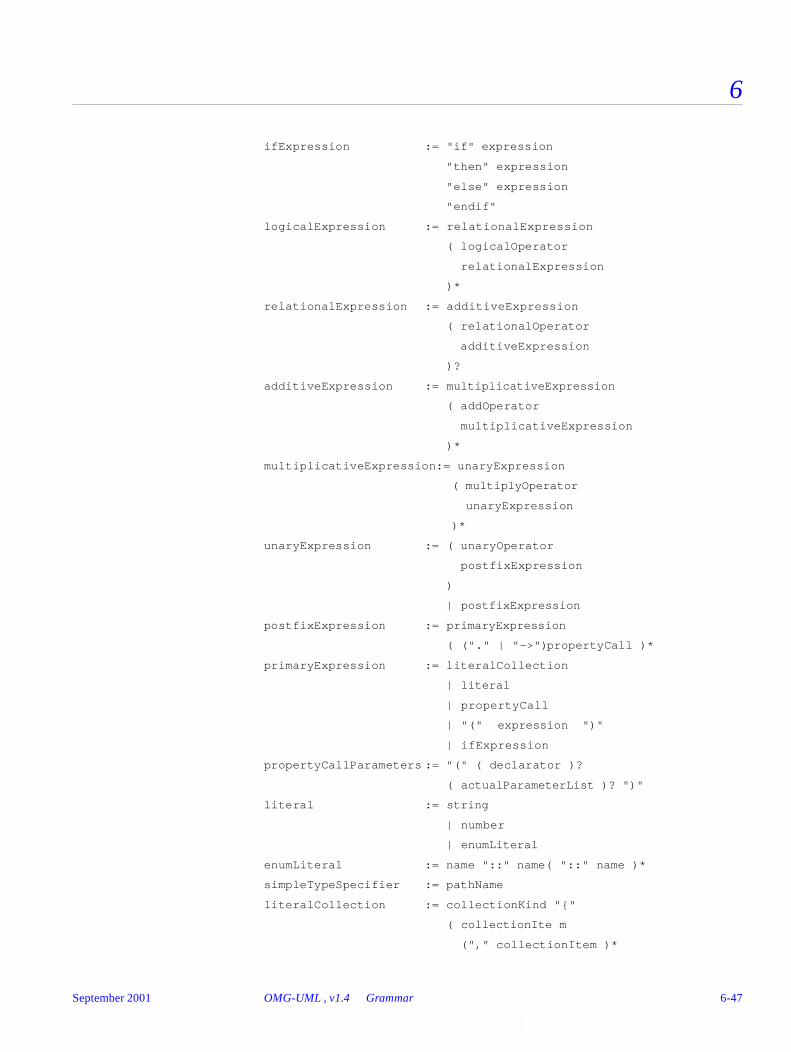
6
ifExpression := "if" expression
"then" expression
"else" expression
"endif"
logicalExpression := relationalExpression
( logicalOperator
relationalExpression
)*
relationalExpression := additiveExpression
( relationalOperator
additiveExpression
)?
additiveExpression := multiplicativeExpression
( addOperator
multiplicativeExpression
)*
multiplicativeExpression:= unaryExpression
( multiplyOperator
unaryExpression
)*
unaryExpression := ( unaryOperator
postfixExpression
)
| postfixExpression
postfixExpression := primaryExpression
( ("." | "->")propertyCall )*
primaryExpression := literalCollection
| literal
| propertyCall
| "(" expression ")"
| ifExpression
propertyCallParameters := "(" ( declarator )?
( actualParameterList )? ")"
literal := string
| number
| enumLiteral
enumLiteral := name "::" name( "::" name )*
simpleTypeSpecifier := pathName
literalCollection := collectionKind "{"
( collectionIte m
("," collectionItem )*
September 2001 OMG-UML , v1.4 Grammar 6-47
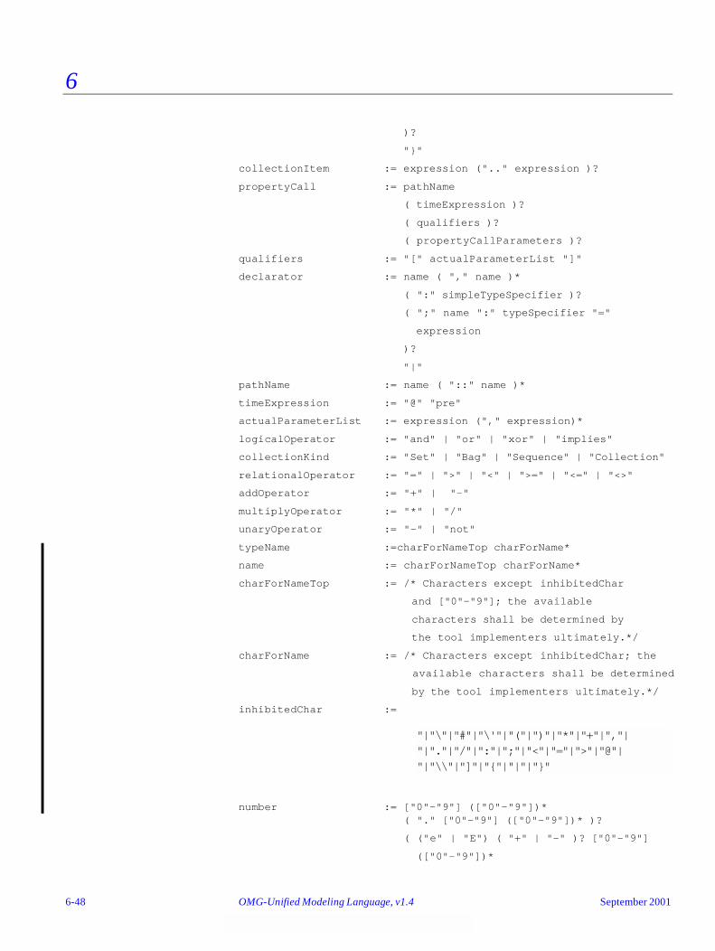
6
)?
"}"
collectionItem := expression (".." expression )?
propertyCall := pathName
( timeExpression )?
( qualifiers )?
( propertyCallParameters )?
qualifiers := "[" actualParameterList "]"
declarator := name ( "," name )*
( ":" simpleTypeSpecifier )?
( ";" name ":" typeSpecifier "="
expression
)?
"|"
pathName := name ( "::" name )*
timeExpression := "@" "pre"
actualParameterList := expression ("," expression)*
logicalOperator := "and" | "or" | "xor" | "implies"
collectionKind := "Set" | "Bag" | "Sequence" | "Collection"
relationalOperator := "=" | ">" | "<" | ">=" | "<=" | "<>"
addOperator := "+" | "-"
multiplyOperator := "*" | "/"
unaryOperator := "-" | "not"
typeName :=charForNameTop charForName*
name := charForNameTop charForName*
charForNameTop := /* Characters except inhibitedChar
and ["0"-"9"]; the available
characters shall be determined by
the tool implementers ultimately.*/
charForName := /* Characters except inhibitedChar; the
available characters shall be determined
by the tool implementers ultimately.*/
inhibitedChar :=
number := ["0"-"9"] (["0"-"9"])*( "." ["0"-"9"] (["0"-"9"])* )?
( ("e" | "E") ( "+" | "-" )? ["0"-"9"]
(["0"-"9"])*
"|"\"|"#"|"\'"|"("|")"|"*"|"+"|","| "|"."|"/"|":"|";"|"<"|"="|">"|"@"| ["|"\\"|"]"|"{"|"|"|"}"
6-48 OMG-Unified Modeling Language, v1.4 September 2001
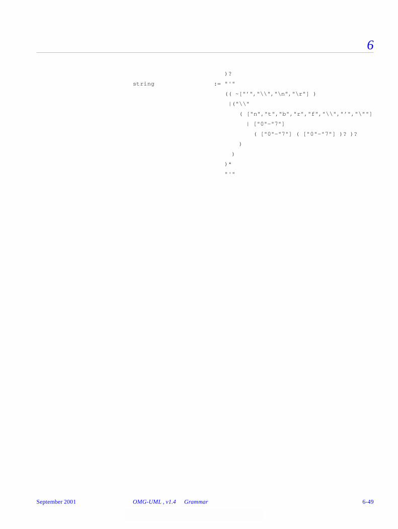
6
)?
string := "'"
(( ~["’","\\","\n","\r"] )
|("\\"
( ["n","t","b","r","f","\\","’","\""]
| ["0"-"7"]
( ["0"-"7"] ( ["0"-"7"] )? )?
)
)
)*
"'"
September 2001 OMG-UML , v1.4 Grammar 6-49

6
6-50 OMG-Unified Modeling Language, v1.4 September 2001
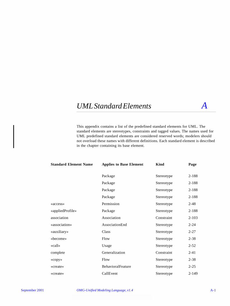
UML Standard Elements A
This appendix contains a list of the predefined standard elements for UML. The standard elements are stereotypes, constraints and tagged values. The names used for UML predefined standard elements are considered reserved words; modelers should not overload these names with different definitions. Each standard element is described in the chapter containing its base element.
Standard Element Name Applies to Base Element Kind Page
Package Stereotype 2-188
Package Stereotype 2-188
Package Stereotype 2-188
Package Stereotype 2-188
«access» Permission Stereotype 2-48
«appliedProfile» Package Stereotype 2-188
association Association Constraint 2-103
«association» AssociationEnd Stereotype 2-24
«auxiliary» Class Stereotype 2-27
«become» Flow Stereotype 2-38
«call» Usage Stereotype 2-52
complete Generalization Constraint 2-41
«copy» Flow Stereotype 2-38
«create» BehavioralFeature Stereotype 2-25
«create» CallEvent Stereotype 2-149
September 2001 OMG-Unified Modeling Language, v1.4 A-1
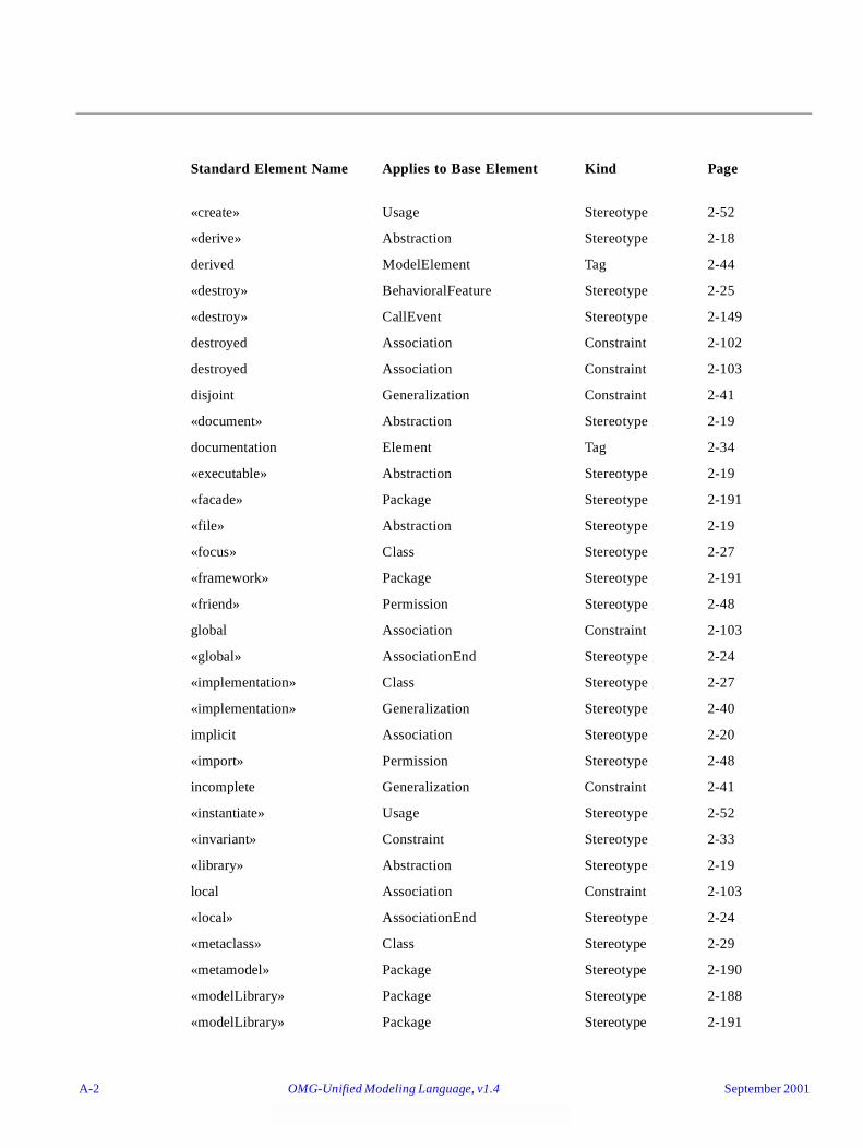
Standard Element Name Applies to Base Element Kind Page
«create» Usage Stereotype 2-52
«derive» Abstraction Stereotype 2-18
derived ModelElement Tag 2-44
«destroy» BehavioralFeature Stereotype 2-25
«destroy» CallEvent Stereotype 2-149
destroyed Association Constraint 2-102
destroyed Association Constraint 2-103
disjoint Generalization Constraint 2-41
«document» Abstraction Stereotype 2-19
documentation Element Tag 2-34
«executable» Abstraction Stereotype 2-19
«facade» Package Stereotype 2-191
«file» Abstraction Stereotype 2-19
«focus» Class Stereotype 2-27
«framework» Package Stereotype 2-191
«friend» Permission Stereotype 2-48
global Association Constraint 2-103
«global» AssociationEnd Stereotype 2-24
«implementation» Class Stereotype 2-27
«implementation» Generalization Stereotype 2-40
implicit Association Stereotype 2-20
«import» Permission Stereotype 2-48
incomplete Generalization Constraint 2-41
«instantiate» Usage Stereotype 2-52
«invariant» Constraint Stereotype 2-33
«library» Abstraction Stereotype 2-19
local Association Constraint 2-103
«local» AssociationEnd Stereotype 2-24
«metaclass» Class Stereotype 2-29
«metamodel» Package Stereotype 2-190
«modelLibrary» Package Stereotype 2-188
«modelLibrary» Package Stereotype 2-191
A-2 OMG-Unified Modeling Language, v1.4 September 2001

Standard Element Name Applies to Base Element Kind Page
new Association Constraint 2-102
new Association Constraint 2-103
overlapping Generalization Constraint 2-41
parameter Association Constraint 2-103
«parameter» AssociationEnd Stereotype 2-24
persistence Association Tag 2-20
persistence Attribute Tag 2-50
persistence Classifier Tag 2-29
persistent Association Tag 2-102
«postcondition» Constraint Stereotype 2-33
«powertype» Class Stereotype 2-29
«precondition» Constraint Stereotype 2-33
«process» Classifier Stereotype 2-29
«profile» Package Stereotype 2-191
«realize» Abstraction Stereotype 2-18
«refine» Abstraction Stereotype 2-18
«requirement» Comment Stereotype 2-31
«responsibility» Comment Stereotype 2-31
self Association Constraint 2-103
«self» AssociationEnd Stereotype 2-24
semantics Classifier Tag 2-29
semantics Operation Tag 2-46
«send» Usage Stereotype 2-52
«signalflow» ObjectFlowState Stereotype 2-180
«source» Abstraction Stereotype 2-19
«stateInvariant» Constraint Stereotype 2-33
«stub» Package Stereotype 2-191
«systemModel» Package Stereotype 2-190
«table» Abstraction Stereotype 2-19
«thread» Classifier Stereotype 2-29
«topLevel» Package Stereotype 2-191
«trace» Abstraction Stereotype 2-18
September 2001 OMG-UML , v1.4 A-3
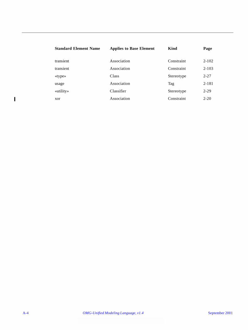
Standard Element Name Applies to Base Element Kind Page
transient Association Constraint 2-102
transient Association Constraint 2-103
«type» Class Stereotype 2-27
usage Association Tag 2-181
«utility» Classifier Stereotype 2-29
xor Association Constraint 2-20
A-4 OMG-Unified Modeling Language, v1.4 September 2001

Glossary B
This glossary defines the terms that are used to describe the Unified Modeling Language (UML) and the Meta Object Facility (MOF). In addition to UML and MOF specific terminology, it includes related terms from OMG standards and object-oriented analysis and design methods, as well as the domain of object repositories and meta data managers. Glossary entries are organized alphabetically and MOF specific entries are identified as ‘[MOF]’.
B.1 Notation Conventions
The entries in the glossary usually begin with a lowercase letter. An initial uppercase letter is used when a word is usually capitalized in standard practice. Acronyms are all capitalized, unless they traditionally appear in all lowercase.
When one or more words in a multi-word term is enclosed in brackets, it indicates that those words are optional when referring to the term. For example, use case [class] may be referred to as simply use case.
The following conventions are used in this glossary:
• Contrast: <term>Refers to a term that has an opposed or substantively different meaning.
• See: <term>Refers to a related term that has a similar, but not synonymous meaning.
• Synonym: <term>Indicates that the term has the same meaning as another term, which is referenced.
• Acronym: <term>Indicates that the term is an acronym. The reader is usually referred to the spelled-out term for the definition, unless the spelled-out term is rarely used.
September 2001 OMG-Unified Modeling Language, v1.4 B-1
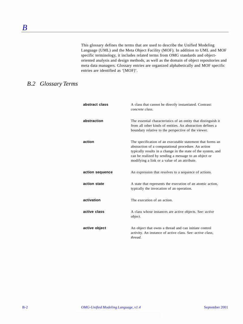
B
This glossary defines the terms that are used to describe the Unified Modeling Language (UML) and the Meta Object Facility (MOF). In addition to UML and MOF specific terminology, it includes related terms from OMG standards and object-oriented analysis and design methods, as well as the domain of object repositories and meta data managers. Glossary entries are organized alphabetically and MOF specific entries are identified as ‘[MOF]’.
B.2 Glossary Terms
abstract class A class that cannot be directly instantiated. Contrast: concrete class.
abstraction The essential characteristics of an entity that distinguish it from all other kinds of entities. An abstraction defines a boundary relative to the perspective of the viewer.
action The specification of an executable statement that forms an abstraction of a computational procedure. An action typically results in a change in the state of the system, and can be realized by sending a message to an object or modifying a link or a value of an attribute.
action sequence An expression that resolves to a sequence of actions.
action state A state that represents the execution of an atomic action, typically the invocation of an operation.
activation The execution of an action.
active class A class whose instances are active objects. See: active object.
active object An object that owns a thread and can initiate control activity. An instance of active class. See: active class, thread.
B-2 OMG-Unified Modeling Language, v1.4 September 2001

B
activity graph A special case of a state machine that is used to model processes involving one or more classifiers. Contrast: statechart diagram.
actor [class] A coherent set of roles that users of use cases play when interacting with these use cases. An actor has one role for each use case with which it communicates.
actual parameter Synonym: argument.
aggregate [class] A class that represents the “whole” in an aggregation (whole-part) relationship. See: aggregation.
aggregation A special form of association that specifies a whole-part relationship between the aggregate (whole) and a component part. See: composition.
analysis The part of the software development process whose primary purpose is to formulate a model of the problem domain. Analysis focuses what to do, design focuses on how to do it. Contrast: design.
analysis time Refers to something that occurs during an analysis phase of the software development process. See: design time, modeling time.
architecture The organizational structure and associated behavior of a system. An architecture can be recursively decomposed into parts that interact through interfaces, relationships that connect parts, and constraints for assembling parts. Parts that interact through interfaces include classes, components and subsystems.
argument A binding for a parameter that resolves to a run-time instance. Synonym: actual parameter. Contrast: parameter.
artifact A physical piece of information that is used or produced by a software development process. Examples of Artifacts include models, source files, scripts, and binary executable files. An artifact may constitute the implementation of a deployable component. Synonym: product. Contrast: component.
association The semantic relationship between two or more classifiers that specifies connections among their instances.
September 2001 OMG-UML , v1.4 B-3
B
association class A model element that has both association and class properties. An association class can be seen as an association that also has class properties, or as a class that also has association properties.
association end The endpoint of an association, which connects the association to a classifier.
attribute A feature within a classifier that describes a range of values that instances of the classifier may hold.
auxiliary class A stereotyped class that supports another more central or fundamental class, typically by implementing secondary logic or control flow. Auxiliary classes are typically used together with focus classes, and are particularly useful for specifying the secondary business logic or control flow of components during design. See also: focus.
behavior The observable effects of an operation or event, including its results.
behavioral feature A dynamic feature of a model element, such as an operation or method.
behavioral model aspect
A model aspect that emphasizes the behavior of the instances in a system, including their methods, collaborations, and state histories.
binary association An association between two classes. A special case of an n-ary association.
binding The creation of a model element from a template by supplying arguments for the parameters of the template.
boolean An enumeration whose values are true and false.
boolean expression An expression that evaluates to a boolean value.
cardinality The number of elements in a set. Contrast: multiplicity.
child In a generalization relationship, the specialization of another element, the parent. See: subclass, subtype. Contrast: parent.
call An action state that invokes an operation on a classifier.
B-4 OMG-Unified Modeling Language, v1.4 September 2001
B
class A description of a set of objects that share the same attributes, operations, methods, relationships, and semantics. A class may use a set of interfaces to specify collections of operations it provides to its environment. See: interface.
classifier A mechanism that describes behavioral and structural features. Classifiers include interfaces, classes, datatypes, and components.
classification The assignment of an object to a classifier. See dynamic classification, multiple classification and static classification.
class diagram A diagram that shows a collection of declarative (static) model elements, such as classes, types, and their contents and relationships.
client A classifier that requests a service from another classifier. Contrast: supplier.
collaboration The specification of how an operation or classifier, such as a use case, is realized by a set of classifiers and associations playing specific roles used in a specific way. The collaboration defines an interaction. See: interaction.
collaboration diagram A diagram that shows interactions organized around the structure of a model, using either classifiers and associations or instances and links. Unlike a sequence diagram, a collaboration diagram shows the relationships among the instances. Sequence diagrams and collaboration diagrams express similar information, but show it in different ways. See: sequence diagram.
comment An annotation attached to an element or a collection of elements. A note has no semantics. Contrast: constraint.
compile time Refers to something that occurs during the compilation of a software module. See: modeling time, run time.
component A modular, deployable, and replaceable part of a system that encapsulates implementation and exposes a set of interfaces. A component is typically specified by one or more classifiers (e.g., implementation classes) that reside on it, and may be implemented by one or more artifacts (e.g., binary, executable, or script files). Contrast: artifact.
September 2001 OMG-UML , v1.4 B-5
B
component diagram A diagram that shows the organizations and dependencies among components.
composite [class] A class that is related to one or more classes by a composition relationship. See: composition.
composite aggregation Synonym: composition.
composite state A state that consists of either concurrent (orthogonal) substates or sequential (disjoint) substates. See: substate.
composition A form of aggregation which requires that a part instance be included in at most one composite at a time, and that the composite object is responsible for the creation and destruction of the parts. Composition may be recursive. Synonym: composite aggregation.
concrete class A class that can be directly instantiated. Contrast: abstract class.
concurrency The occurrence of two or more activities during the same time interval. Concurrency can be achieved by interleaving or simultaneously executing two or more threads. See: thread.
concurrent substate A substate that can be held simultaneously with other substates contained in the same composite state. See: composite state. Contrast: disjoint substate.
constraint A semantic condition or restriction. Certain constraints are predefined in the UML, others may be user defined. Constraints are one of three extensibility mechanisms in UML. See: tagged value, stereotype.
container 1. An instance that exists to contain other instances, and that provides operations to access or iterate over its contents. (for example, arrays, lists, sets). 2. A component that exists to contain other components.
containment hierarchy A namespace hierarchy consisting of model elements, and the containment relationships that exist between them. A containment hierarchy forms a graph.
context A view of a set of related modeling elements for a particular purpose, such as specifying an operation.
B-6 OMG-Unified Modeling Language, v1.4 September 2001
B
datatype A descriptor of a set of values that lack identity and whose operations do not have side effects. Datatypes include primitive pre-defined types and user-definable types. Pre-defined types include numbers, string and time. User-definable types include enumerations.
defining model [MOF] The model on which a repository is based. Any number of repositories can have the same defining model.
delegation The ability of an object to issue a message to another object in response to a message. Delegation can be used as an alternative to inheritance. Contrast: inheritance.
dependency A relationship between two modeling elements, in which a change to one modeling element (the independent element) will affect the other modeling element (the dependent element).
deployment diagram A diagram that shows the configuration of run-time processing nodes and the components, processes, and objects that live on them. Components represent run-time manifestations of code units. See: component diagrams.
derived element A model element that can be computed from another element, but that is shown for clarity or that is included for design purposes even though it adds no semantic information.
design The part of the software development process whose primary purpose is to decide how the system will be implemented. During design strategic and tactical decisions are made to meet the required functional and quality requirements of a system.
design time Refers to something that occurs during a design phase of the software development process. See: modeling time. Contrast: analysis time.
development process A set of partially ordered steps performed for a given purpose during software development, such as constructing models or implementing models.
September 2001 OMG-UML , v1.4 B-7
B
diagram A graphical presentation of a collection of model elements, most often rendered as a connected graph of arcs (relationships) and vertices (other model elements). UML supports the following diagrams: class diagram, object diagram, use case diagram, sequence diagram, collaboration diagram, state diagram, activity diagram, component diagram, and deployment diagram.
disjoint substate A substate that cannot be held simultaneously with other substates contained in the same composite state. See: composite state. Contrast: concurrent substate.
distribution unit A set of objects or components that are allocated to a process or a processor as a group. A distribution unit can be represented by a run-time composite or an aggregate.
domain An area of knowledge or activity characterized by a set of concepts and terminology understood by practitioners in that area.
dynamic classification A semantic variation of generalization in which an object may change its classifier. Contrast: static classification.
element An atomic constituent of a model.
entry action An action executed upon entering a state in a state machineregardless of the transition taken to reach that state.
enumeration A list of named values used as the range of a particular attribute type. For example, RGBColor = {red, green, blue}. Boolean is a predefined enumeration with values from the set {false, true}.
event The specification of a significant occurrence that has a location in time and space. In the context of state diagrams, an event is an occurrence that can trigger a transition.
exit action An action executed upon exiting a state in a state machineregardless of the transition taken to exit that state.
export In the context of packages, to make an element visible outside its enclosing namespace. See: visibility. Contrast: export [OMA], import.
expression A string that evaluates to a value of a particular type. For example, the expression “(7 + 5 * 3)” evaluates to a value of type number.
B-8 OMG-Unified Modeling Language, v1.4 September 2001
B
extend A relationship from an extension use case to a base use case, specifying how the behavior defined for the extension use case augments (subject to conditions specified in the extension) the behavior defined for the base use case. The behavior is inserted at the location defined by the extension point in the base use case. The base use case does not depend on performing the behavior of the extension use case. See extension point, include.
facade A stereotyped package containing only references to model elements owned by another package. It is used to provide a ‘public view’ of some of the contents of a package.
feature A property, like operation or attribute, which is encapsulated within a classifier, such as an interface, a class, or a datatype.
final state A special kind of state signifying that the enclosingcomposite state or the entire state machine is completed.
fire To execute a state transition. See: transition.
focus class A stereotyped class that defines the core logic or control flow for one or more auxiliary classes that support it. Focus classes are typically used together with one or more auxiliary classes, and are particularly useful for specifying the core business logic or control flow of components during design. See also: auxiliary.
focus of control A symbol on a sequence diagram that shows the period of time during which an object is performing an action, either directly or through a subordinate procedure.
formal parameter Synonym: parameter.
framework A stereotyped package that contains model elements which specify a reusable architecture for all or part of a system. Frameworks typically include classes, patterns or templates. When frameworks are specialized for an application domain, they are sometimes referred to as application frameworks. See: pattern.
generalizable element A model element that may participate in a generalization relationship. See: generalization.
September 2001 OMG-UML , v1.4 B-9
B
generalization A taxonomic relationship between a more general element and a more specific element. The more specific element is fully consistent with the more general element and contains additional information. An instance of the more specific element may be used where the more general element is allowed. See: inheritance.
guard condition A condition that must be satisfied in order to enable an associated transition to fire.
implementation A definition of how something is constructed or computed. For example, a class is an implementation of a type, a method is an implementation of an operation.
implementation class A stereotyped class that specifies the implementation of a class in some programming language (e.g., C++, Smalltalk, Java) in which an instance may not have more than one class. An Implementation class is said to realize a type if it provides all of the operations defined for the type with the same behavior as specified for the type's operations. See also: type.
implementation inheritance
The inheritance of the implementation of a more general element. Includes inheritance of the interface. Contrast: interface inheritance.
import In the context of packages, a dependency that shows the packages whose classes may be referenced within a given package (including packages recursively embedded within it). Contrast: export.
include A relationship from a base use case to an inclusion use case, specifying how the behavior for the base use case contains the behavior of the inclusion use case. The behavior is included at the location which is defined in the base use case. The base use case depends on performing the behavior of the inclusion use case, but not on its structure (i.e., attributes or operations). See extend.
inheritance The mechanism by which more specific elements incorporate structure and behavior of more general elements related by behavior. See generalization.
initial state A special kind of state signifying the source for a single transition to the default state of the composite state.
B-10 OMG-Unified Modeling Language, v1.4 September 2001
B
instance An entity that has unique identity, a set of operations that can be applied to it, and state that stores the effects of the operations. See: object.
interaction A specification of how stimuli are sent between instances to perform a specific task. The interaction is defined in the context of a collaboration. See collaboration.
interaction diagram A generic term that applies to several types of diagrams that emphasize object interactions. These include collaboration diagrams and sequence diagrams.
interface A named set of operations that characterize the behavior of an element.
interface inheritance The inheritance of the interface of a more general element. Does not include inheritance of the implementation. Contrast: implementation inheritance.
internal transition A transition signifying a response to an event without changing the state of an object.
layer The organization of classifiers or packages at the same level of abstraction. A layer represents a horizontal slice through an architecture, whereas a partition represents a vertical slice. Contrast: partition.
link A semantic connection among a tuple of objects. An instance of an association. See: association.
link end An instance of an association end. See: association end.
message A specification of the conveyance of information from one instance to another, with the expectation that activity will ensue. A message may specify the raising of a signal or the call of an operation.
metaclass A class whose instances are classes. Metaclasses are typically used to construct metamodels.
meta-metamodel A model that defines the language for expressing a metamodel. The relationship between a meta-metamodel and a metamodel is analogous to the relationship between a metamodel and a model.
metamodel A model that defines the language for expressing a model.
September 2001 OMG-UML , v1.4 B-11
B
metaobject A generic term for all metaentities in a metamodeling language. For example, metatypes, metaclasses, metaattributes, and metaassociations.
method The implementation of an operation. It specifies the algorithm or procedure associated with an operation.
model
[MOF]
An abstraction of a physical system with a certain purpose. See: physical system.
Usage note: In the context of the MOF specification, which describes a meta-metamodel, for brevity the meta-metamodel is frequently to as simply the model.
model aspect A dimension of modeling that emphasizes particular qualities of the metamodel. For example, the structural model aspect emphasizes the structural qualities of the metamodel.
model elaboration The process of generating a repository type from a published model. Includes the generation of interfaces and implementations which allows repositories to be instantiated and populated based on, and in compliance with, the model elaborated.
model element
[MOF]
An element that is an abstraction drawn from the system being modeled. Contrast: view element.
In the MOF specification model elements are considered to be metaobjects.
model library A stereotyped package that contains model elements which are intended to be reused by other packages. A model library differs from a profile in that a model library does not extend the metamodel using stereotypes and tagged definitions. A model library is analogous to a class library in some programming languages.
modeling time Refers to something that occurs during a modeling phase of the software development process. It includes analysis time and design time. Usage note: When discussing object systems, it is often important to distinguish between modeling-time and run-time concerns. See: analysis time, design time. Contrast: run time.
module A software unit of storage and manipulation. Modules include source code modules, binary code modules, and executable code modules. See: component.
B-12 OMG-Unified Modeling Language, v1.4 September 2001
B
multiple classification A semantic variation of generalization in which an object may belong directly to more than one classifier. See: static classification, dynamic classification.
multiple inheritance A semantic variation of generalization in which a type may have more than one supertype. Contrast: single inheritance.
multiplicity A specification of the range of allowable cardinalities that a set may assume. Multiplicity specifications may be given for roles within associations, parts within composites, repetitions, and other purposes. Essentially a multiplicity is a (possibly infinite) subset of the non-negative integers. Contrast: cardinality.
multi-valued [MOF] A model element with multiplicity defined whose Multiplicity Type:: upper attribute is set to a number greater than one. The term multi-valued does not pertain to the number of values held by an attribute, parameter, etc. at any point in time. Contrast: single-valued.
n-ary association An association among three or more classes. Each instance of the association is an n-tuple of values from the respective classes. Contrast: binary association.
name A string used to identify a model element.
namespace A part of the model in which the names may be defined and used. Within a namespace, each name has a unique meaning. See: name.
node A node is classifier that represents a run-time computational resource, which generally has at least a memory and often processing capability. Run-time objects and components may reside on nodes.
object An entity with a well-defined boundary and identity that encapsulates state and behavior. State is represented by attributes and relationships, behavior is represented by operations, methods, and state machines. An object is an instance of a class. See: class, instance.
object diagram A diagram that encompasses objects and their relationships at a point in time. An object diagram may be considered a special case of a class diagram or a collaboration diagram. See: class diagram, collaboration diagram.
September 2001 OMG-UML , v1.4 B-13
B
object flow state A state in an activity graph that represents the passing of an object from the output of actions in one state to the input of actions in another state.
object lifeline A line in a sequence diagram that represents the existence of an object over a period of time. See: sequence diagram.
operation A service that can be requested from an object to effect behavior. An operation has a signature, which may restrict the actual parameters that are possible.
package A general purpose mechanism for organizing elements into groups. Packages may be nested within other packages.
parameter The specification of a variable that can be changed, passed, or returned. A parameter may include a name, type, and direction. Parameters are used for operations, messages, and events. Synonyms: formal parameter. Contrast: argument.
parameterized element The descriptor for a class with one or more unbound parameters. Synonym: template.
parent In a generalization relationship, the generalization of another element, the child. See: subclass, subtype. Contrast: child.
participate The connection of a model element to a relationship or to a reified relationship. For example, a class participates in an association, an actor participates in a use case.
partition 1. activity graphs: A portion of an activity graphs that organizes the responsibilities for actions. See: swimlane.2. architecture: A set of related classifiers or packages at the same level of abstraction or across layers in a layered architecture. A partition represents a vertical slice through an architecture, whereas a layer represents a horizontal slice. Contrast: layer.
pattern A template collaboration.
persistent object An object that exists after the process or thread that created it has ceased to exist.
postcondition A constraint that must be true at the completion of an operation.
precondition A constraint that must be true when an operation is invoked.
B-14 OMG-Unified Modeling Language, v1.4 September 2001
B
primitive type A pre-defined basic datatype without any substructure, such as an integer or a string.
process 1. A heavyweight unit of concurrency and execution in an operating system. Contrast: thread, which includes heavyweight and lightweight processes. If necessary, an implementation distinction can be made using stereotypes.2. A software development process—the steps and guidelines by which to develop a system.3. To execute an algorithm or otherwise handle something dynamically.
profile A profile is a stereotyped package that contains model elements which have been customized for a specific domain or purpose using extension mechanisms, such as stereotypes, tagged definitions and constraints. A profile may also specify model libraries on which it depends and the metamodel subset that it extends.
projection A mapping from a set to a subset of it.
property A named value denoting a characteristic of an element. A property has semantic impact. Certain properties are predefined in the UML; others may be user defined. See: tagged value.
pseudo-state A vertex in a state machine that has the form of a state, but doesn’t behave as a state. Pseudo-states include initial and history vertices.
physical system 1. The subject of a model. 2. A collection of connected physical units, which can include software, hardware and people, that are organized to accomplish a specific purpose. A physical system can be described by one or more models, possibly from different viewpoints. Contrast: system.
published model [MOF] A model that has been frozen, and becomes available for instantiating repositories and for the support in defining other models. A frozen model’s model elements cannot be changed.
qualifier An association attribute or tuple of attributes whose values partition the set of objects related to an object across an association.
September 2001 OMG-UML , v1.4 B-15
B
receive [a message] The handling of a stimulus passed from a sender instance. See: sender, receiver.
receiver [object] The object handling a stimulus passed from a sender object. Contrast: sender.
reception A declaration that a classifier is prepared to react to the receipt of a signal.
reference 1. A denotation of a model element. 2. A named slot within a classifier that facilitates navigation to other classifiers. Synonym: pointer.
refinement A relationship that represents a fuller specification of something that has already been specified at a certain level of detail. For example, a design class is a refinement of an analysis class.
relationship A semantic connection among model elements. Examples of relationships include associations and generalizations.
repository A facility for storing object models, interfaces, and implementations.
requirement A desired feature, property, or behavior of a system.
responsibility A contract or obligation of a classifier.
reuse The use of a pre-existing artifact.
role The named specific behavior of an entity participating in a particular context. A role may be static (e.g., an association end) or dynamic (e.g., a collaboration role).
run time The period of time during which a computer program executes. Contrast: modeling time.
scenario A specific sequence of actions that illustrates behaviors. A scenario may be used to illustrate an interaction or the execution of a use case instance. See: interaction.
schema [MOF] In the context of the MOF, a schema is analogous to a package which is a container of model elements. Schema corresponds to an MOF package. Contrast: metamodel, package.
B-16 OMG-Unified Modeling Language, v1.4 September 2001
B
semantic variation point A point of variation in the semantics of a metamodel. It provides an intentional degree of freedom for the interpretation of the metamodel semantics.
send [a message] The passing of a stimulus from a sender instance to a receiver instance. See: sender, receiver.
sender [object] The object passing a stimulus to a receiver object. Contrast: receiver.
sequence diagram A diagram that shows object interactions arranged in time sequence. In particular, it shows the objects participating in the interaction and the sequence of messages exchanged. Unlike a collaboration diagram, a sequence diagram includes time sequences but does not include object relationships. A sequence diagram can exist in a generic form (describes all possible scenarios) and in an instance form (describes one actual scenario). Sequence diagrams and collaboration diagrams express similar information, but show it in different ways. See: collaboration diagram.
signal The specification of an asynchronous stimulus communicated between instances. Signals may have parameters.
signature The name and parameters of a behavioral feature. A signature may include an optional returned parameter.
single inheritance A semantic variation of generalization in which a type may have only one supertype. Synonym: multiple inheritance [OMA]. Contrast: multiple inheritance.
single valued [MOF] A model element with multiplicity defined is single valued when its Multiplicity Type:: upper attribute is set to one. The term single-valued does not pertain to the number of values held by an attribute, parameter, etc., at any point in time, since a single-valued attribute (for instance, with a multiplicity lower bound of zero) may have no value. Contrast: multi-valued.
specification A declarative description of what something is or does. Contrast: implementation.
state A condition or situation during the life of an object during which it satisfies some condition, performs some activity, or waits for some event. Contrast: state [OMA].
September 2001 OMG-UML , v1.4 B-17
B
statechart diagram A diagram that shows a state machine. See: state machine.
state machine A behavior that specifies the sequences of states that an object or an interaction goes through during its life in response to events, together with its responses and actions.
static classification A semantic variation of generalization in which an object may not change classifier. Contrast: dynamic classification.
stereotype A new type of modeling element that extends the semantics of the metamodel. Stereotypes must be based on certain existing types or classes in the metamodel. Stereotypes may extend the semantics, but not the structure of pre-existing types and classes. Certain stereotypes are predefined in the UML, others may be user defined. Stereotypes are one of three extensibility mechanisms in UML. See: constraint, tagged value.
stimulus The passing of information from one instance to another, such as raising a signal or invoking an operation. The receipt of a signal is normally considered an event. See: message.
string A sequence of text characters. The details of string representation depend on implementation, and may include character sets that support international characters and graphics.
structural feature A static feature of a model element, such as an attribute.
structural model aspect A model aspect that emphasizes the structure of the objects in a system, including their types, classes, relationships, attributes, and operations.
subactivity state A state in an activity graph that represents the execution of a non-atomic sequence of steps that has some duration.
subclass In a generalization relationship, the specialization of another class; the superclass. See: generalization. Contrast: superclass.
submachine state A state in a state machine which is equivalent to acomposite state but its contents is described by another state machine.
substate A state that is part of a composite state. See: concurrent state, disjoint state.
subpackage A package that is contained in another package.
B-18 OMG-Unified Modeling Language, v1.4 September 2001
B
subsystem A grouping of model elements that represents a behavioral unit in a physical system. A subsystem offers interfaces and has operations. In addition, the model elements of a subsystem can be partitioned into specification and realization elements. See package. See: physical system.
subtype In a generalization relationship, the specialization of another type; the supertype. See: generalization. Contrast: supertype.
superclass In a generalization relationship, the generalization of another class; the subclass. See: generalization. Contrast: subclass.
supertype In a generalization relationship, the generalization of another type; the subtype. See: generalization. Contrast: subtype.
supplier A classifier that provides services that can be invoked by others. Contrast: client.
swimlane A partition on a activity diagram for organizing the responsibilities for actions. Swimlanes typically correspond to organizational units in a business model. See: partition.
synch state A vertex in a state machine used for synchronizing theconcurrent regions of a state machine.
system A top-level subsystem in a model. Contrast: physical system.
tagged value The explicit definition of a property as a name-value pair. In a tagged value, the name is referred as the tag. Certain tags are predefined in the UML; others may be user defined. Tagged values are one of three extensibility mechanisms in UML. See: constraint, stereotype.
template Synonym: parameterized element.
thread [of control] A single path of execution through a program, a dynamic model, or some other representation of control flow. Also, a stereotype for the implementation of an active object as lightweight process. See process.
time event An event that denotes the time elapsed since the current state was entered. See: event.
September 2001 OMG-UML , v1.4 B-19
B
time expression An expression that resolves to an absolute or relative value of time.
top level A stereotype of package denoting the top-most package in a containment hierarchy. The topLevel stereotype defines the outer limit for looking up names, as namespaces “see” outwards. For example, opLevel subsystem represents the top of the subsystem containment hierarchy.
trace A dependency that indicates a historical or process relationship between two elements that represent the same concept without specific rules for deriving one from the other.
transient object An object that exists only during the execution of the process or thread that created it.
transition A relationship between two states indicating that an object in the first state will perform certain specified actions and enter the second state when a specified event occurs and specified conditions are satisfied. On such a change of state, the transition is said to fire.
type A stereotyped class that specifies a domain of objects together with the operations applicable to the objects, without defining the physical implementation of those objects. A type may not contain any methods, maintain its own thread of control, or be nested. However, it may have attributes and associations. Although an object may have at most one implementation class, it may conform to multiple different types. See also: implementation class Contrast: interface.
type expression An expression that evaluates to a reference to one or more types.
uninterpreted A placeholder for a type or types whose implementation is not specified by the UML. Every uninterpreted value has a corresponding string representation. See: any [CORBA].
usage A dependency in which one element (the client) requires the presence of another element (the supplier) for its correct functioning or implementation.
B-20 OMG-Unified Modeling Language, v1.4 September 2001

B
use case [class] The specification of a sequence of actions, including variants, that a system (or other entity) can perform, interacting with actors of the system. See: use case instances.
use case diagram A diagram that shows the relationships among actors and use cases within a system.
use case instance The performance of a sequence of actions being specified in a use case. An instance of a use case. See: use case class.
use case model A model that describes a system’s functional requirements in terms of use cases.
utility A stereotype that groups global variables and procedures in the form of a class declaration. The utility attributes and operations become global variables and global procedures, respectively. A utility is not a fundamental modeling construct, but a programming convenience.
value An element of a type domain.
vertex A source or a target for a transition in a state machine. A vertex can be either a state or a pseudo-state. See: state, pseudo-state.
view A projection of a model, which is seen from a given perspective or vantage point and omits entities that are not relevant to this perspective.
view element A view element is a textual and/or graphical projection of a collection of model elements.
view projection A projection of model elements onto view elements. A view projection provides a location and a style for each view element.
visibility An enumeration whose value (public, protected, or private) denotes how the model element to which it refers may be seen outside its enclosing namespace.
September 2001 OMG-UML , v1.4 B-21
B
B-22 OMG-Unified Modeling Language, v1.4 September 2001
Index
Aabstract class 3-38abstract operation 3-46abstract syntax section 2-9Abstraction 2-17, 2-19access 3-63, 3-91access (Permission) 2-48, 2-198, 2-203accessing a package 3-63accessing elements 2-47Action 2-98, 2-107, 2-114action (ActionSequence) 2-99action (Message) 2-124action expression 3-146action state 3-159ActionExpression 2-87action-object flow relationships 3-164ActionSequence 2-99, 2-107ActionState 2-178, 2-182, 2-184activation 3-108, 3-110activator (Message )2-124active class 2-26active object 3-129active state 2-161active state configuration 2-162activity diagra m3-156activity graph3-156Activity Graphs Package 2-175activity in a state 2-162activity state 3-159, 3-160ActivityGraph 2-177, 2-181, 2-184Actor 2-135, 2-138, 2-140actor 3-97actor relationship 3-99actualArgument (Action) 2-99addition (Include) 2-137addOnly (ChangeableKind) 2-22, 2-50, 2-88addOnly (keyword) 3-73adornment
on association 3-68order 3-74
after (keyword) 3-144aggregate (AggregationKind) 2-22, 2-87aggregation 3-72aggregation (AssociationEnd) 2-22, 2-66AggregationKind 2-87alias (ElementImport) 2-189angle bracket
for binding argument 3-55annotatedElement (Comment) 2-31architecture of metamodel 2-3ArgListsExpression 2-87Argument 2-99, 2-107argument (Binding) 2-26argument (Stimulus) 2-106argument list 3-134arrow
dashedfor constraint 3-27for dependency 3-90for extend 3-98for flow relationship 3-65
for include 3-98for instance of 3-93for object flow 3-164for realization 3-49for return 3-112
solidfor call 3-112for generalization 3-86for message 3-111for navigation 3-73for transition 3-146
Artifacts 1-2development project 1-2UML-defining Artifacts 1-2
artifactsUML-defining 1-2
Association 2-19, 2-52, 2-65association 3-68association (AssociationEnd) 2-24association (Classifier) 2-28association (keyword) 3-85association (Link) 2-103association (LinkEnd) 2-103association class 3-69, 3-77association end 3-68, 3-71association nam e3-68association role 3-126AssociationClass 2-21, 2-53, 2-67AssociationEnd 2-21, 2-53, 2-65associationEnd (Attribute) 2-25associationEnd (LinkEnd) 2-103AssociationEndRole 2-120, 2-124AssociationRole 2-120, 2-125Attribute 2-24, 2-54attribute 3-38, 3-41
in objec t3-65attribute (AttributeLink) 2-100AttributeLink 2-100, 2-107availableContents (ClassifierRole) 2-121availableFeature (ClassifierRole) 2-121availableQualifier (AssociationEndRole )2-120
BBag 6-40bar
for stub state 3-153for stubbed transition 3-149for synchronization, fork, join 3-147
base (AssociationEndRole) 2-120base (AssociationRole) 2-121base (ClassifierRole) 2-121base (Extend) 2-136base (Include) 2-137baseClass (Stereotype) 2-78Basic Values and Types 6-7become (Flow) 2-38become (keyword) 3-65behavior
of operation as note 3-46Behavioral Elements Package 2-94BehavioralFeature 2-25, 2-54
September 2001 OMG-Unified Modeling Language, v1.4 Index-1
Index
binary association 3-68bind (keyword) 3-91Binding 2-25, 2-55, 2-73binding 3-54body (Comment) 2-30body (Constraint) 2-32, 2-77body (Expression) 2-89body (Mapping) 2-90body (Method) 2-42boldface
for class name 3-36for compartment name 3-39for special list element 3-37
Boolean 2-87, 6-35Boolean propert y3-30BooleanExpression 2-87bound (SynchState) 2-155, 2-170bound element 3-54braces
for constraint 3-27, 3-28for property string 3-29, 3-38, 3-42
branch 3-160, 3-162branch point3-151bull’s eye
for final state 3-142
Ccall 3-108call (Usage) 2-52call event 3-144CallAction 2-100, 2-107, 2-115CallConcurrencyKind 2-88CallEvent 2-148CallState 2-179, 2-182chain of transitions 3-151changeability 3-73changeability (AssociationEnd) 2-22changeability (Attribute) 2-50changeable (ChangeableKind) 2-22, 2-50, 2-88ChangeableKind 2-88ChangeEvent 2-149changeExpression (ChangeEvent) 2-149child (Generalization) 2-40choice (PseudostateKind) 2-92, 2-152circle
bull’s eyefor final stat e3-142
filledfor initial state 3-141
for history state 3-149for interface 3-51for junction 3-151for synch state 3-155
Class 2-26, 2-55, 2-68class 3-35
declared in another class 3-82class diagram 3-34class in state 3-65class scope
attribute 3-43operation 3-45
Classifier 2-28, 2-56classifier 3-35classifier (Instanc e )2-102classifier (ScopeKind)2-37, 2-50, 2-92classifier rol e3-125ClassifierInState 2-179ClassifierRole 2-121, 2-125client (Dependency) 2-34clientDependency (ModelElement) 2-43Collaboration 2-121, 2-122, 2-126, 2-127, 2-129collaboration 3-115, 3-122collaboration diagram 3-115, 3-117collaboration role 3-125collaborationMultiplicity (AssociationEndRole) 2-120Collaborations Package 2-115Collect Operation 6-24Collection 6-36Collection Operations 6-22Collection Type Hierarchy and Type Conformance Rules 6-21Collection-Related Typed 6-36Collections 6-20Collections of Collections 6-21colon
for return type3-44for sequence expression 3-132for type 3-42, 3-45, 3-53, 3-62, 3-65, 3-72, 3-81, 3-125, 3-175,
3-177Combining Properties 6-14Comment 2-30, 2-59, 6-11comment 3-26, 3-28Common Behavior Package 2-94communication association 3-97, 3-99communication relationship 2-137, 2-142communicationConnection (Message) 2-124communicationLink (Stimulus) 2-106compartment 3-38
name 3-39special 3-36
complete (Generalization) 2-41complete (keyword) 3-87completion event 2-165completion transition 2-165complex transition 3-147, 3-148Component 2-31, 2-59component 3-176
on nod e3-176component diagram 3-170ComponentInstance 2-100, 2-108composite (AggregationKind) 2-22, 2-66, 2-87composite object 3-67composite state 3-141, 3-155CompositeState 2-149, 2-156, 2-162composition 3-67, 3-81Compound transition 2-164concurrency
in state machine 2-168of operation 3-45synchronizing 2-169
concurrency (Operation) 2-46concurrent (CallConcurrencyKind) 2-46, 2-88concurrent lifeline s3-109
Index-2 OMG-Unified Modeling Language, v1.4 September 2001

Index
concurrent substate 3-141condition (Extend) 2-136condition event 3-144conditional fork 3-170conflict 2-168connection (Association) 2-20connection (Link) 2-103constant
enumeration 3-57constrainedElement (Constraint) 2-32, 2-77constrainedStereotype (Constraint) 2-77Constraint 2-32, 2-59, 2-73, 2-80constraint 3-26, 3-28
as list element 3-27constraint (ModelElement) 2-43, 2-78constraint language 2-10, 2-83, 3-27container (StateVertex) 2-154contents (Partition) 2-180context 3-115context (Exception) 2-101context (Interaction) 2-123, 2-124context (Signal) 2-106context (StateMachine) 2-153control flow icon 3-131control flow type 3-135control icons3-166copy (Flow) 2-38copy (keyword) 3-65copying composite 2-66create (BehavioralFeature) 2-25create (CallEvent) 2-149create (Usage) 2-52CreateAction 2-101, 2-108, 2-115creation 3-109, 3-115, 3-135cross
for destruction 3-109cube
for node 3-174
Ddata flow relationship 2-185Data Types Foundation Package 2-85DataType 2-33, 2-60, 2-74, 2-85DataValue 2-101, 2-108, 2-113decision, See</> branchdeepHistory (PseudostateKind) 2-92, 2-151, 2-163default entry 2-162defaultElement (TemplateParameter) 2-51defaultValue (Parameter) 2-47defer (keyword )3-167deferrableEvent (State) 2-153deferred event 2-162, 2-163, 3-167Dependency 2-33, 2-60, 2-73dependency 3-90
subsystem 3-21deployment diagram 3-172deploymentLocation (Component) 2-31Derivation 2-18derivation 3-91derive (Abstraction) 2-18derive (keyword) 3-91
derived (ModelElement) 2-44derived element 3-93descriptor 2-70design patter n3-118destination state 3-147destroy (BehavioralFeature) 2-25destroy (CallEvent) 2-149destroy action 2-115DestroyAction 2-101, 2-108destroyed (Instance) 2-102destroyed (keyword) 3-115destroyed (Link) 2-103destroying composite 2-66destruction 3-109, 3-115, 3-135development project 1-2diamond
filledfor composition 3-81
for aggregation 3-72for branch or merge3-161for merge 3-151for n-ary association 3-79
discriminator 2-41, 3-86, 3-87discriminator (Generalization) 2-40, 2-41disjoint (Generalization) 2-41disjoint (keyword) 3-87disjoint substate 3-141dispatchAction (Stimulus) 2-106do activity 2-162, 3-139doActivity (State) 2-153document (Component) 2-19documentation (Element) 2-34dog-eared rectangle
for note 3-13dot
for navigation 3-13for sequence expression3-132
double colonfor pathname 3-36, 3-62
double dotfor integer range3-75
dynamic choice point 3-152dynamic concurrency 3-169dynamicArguments (ActionState) 2-178dynamicArguments (SubactivityState) 2-181dynamicMultiplicity (ActionState) 2-178dynamicMultiplicity (SubactivityState) 2-181
Eeffect (Transition) 2-156elapsed-time event3-144Element 2-34, 2-60element property 3-29ElementImport 2-189, 2-192ElementOwnership 2-34, 2-60ElementResidence 2-35, 2-60ellipse
dashedfor collaboration 3-119
for use cas e3-96ellipsis
September 2001 OMG-Unified Modeling Language, v1.4 Index-3
Index
for generalization 3-86for missing element 3-39
else (keyword) 3-152enabled transition 2-165entering a concurrent composite stat e2-163entry (ActionState) 2-179entry (State) 2-153entry action 2-161, 3-139entry stub state 3-153Enumeration 2-36, 2-60, 6-35enumeration 3-57enumeration (EnumerationLiteral) 2-36enumeration literal 3-57Enumeration Types 6-8EnumerationLiteral 2-36, 2-60equal sign
for attribute value 3-65for default value 3-45, 3-53for initial value 3-42for tagged value3-29
Event 2-150, 2-161event 3-143event processing 2-167event signature 3-146examples sectio n3-5Exception 2-101, 2-108, 2-114executable (Component) 2-19, 2-31Exists Operation 6-26exit (State) 2-153exit action 2-161, 3-139exit stub state 3-153exiting a concurrent state 2-163exiting a non-concurrent state 2-163Expression 2-88expression 3-11expression (Guard) 2-151expression (ProgrammingLanguageDataType) 2-49Extend 2-136, 2-138, 2-144extend 3-98extend (UseCase) 2-138extendedElement (Stereotype) 2-79extensibility mechanism 3-29, 3-31extension (Extend) 2-136Extension Mechanisms Foundation Package 2-74extension point3-96extension points compartment3-96ExtensionPoint 2-136, 2-139extensionPoint (Extend) 2-136extensionPoint (UseCase) 2-138
Ffacade (Package) 2-191facade (stereotype) 3-17Facility Implementation Requirements 5-24factored transition pat h3-151false (Boolean) 2-87Feature 2-36, 2-60feature 3-38feature (Classifier) 2-28Features on Types Themselves 6-19file (Component) 2-19
final state 3-142FinalState 2-150, 2-157, 2-163fire a transition2-167Flow 2-37flow relationship 3-65focus of control 3-108, 3-110font usage 3-8ForAll Operation 6-25fork (PseudostateKind) 2-92, 2-151fork of control3-147formalism 2-8Foundation package 2-11four-layer metamodel architecture 2-3framework (Package) 2-191, 2-198framework (stereotype) 3-17friend (Permission) 2-48frozen (ChangeableKind) 2-22, 2-50, 2-88frozen (keyword) 3-43, 3-73full descriptor 2-70
GGeneralizableElement 2-38, 2-60, 2-70Generalization 2-39, 2-61, 2-70
of package 2-198of subsystem 2-201of use cas e2-143
generalization 3-86constraints on 3-87use cas e3-98
generalization (GeneralizableElement) 2-39Geometry 2-89global (AssociationEnd) 2-24global (keyword) 3-85global (LinkEnd) 2-103Goals 1-4Grammar for OCL 6-45graphic construct s3-6graphic marker 3-32group propert y3-39Guard 2-150, 2-157, 2-165guard (Transition) 2-156guard condition 3-146guarded (CallConcurrencyKind) 2-46, 2-88guillemets
for keyword 3-11for stereotype 3-31, 3-38
HHarel statechart 2-175hidden element 3-39high-level transition 2-164history
deep 2-163shallow 2-163
history state 3-149hyperlink 3-7
Iicon
for stereotype 3-32, 3-38icon (Stereotype) 2-78
Index-4 OMG-Unified Modeling Language, v1.4 September 2001
Index
icons 3-6implementation (Generalization) 2-40implementation class
and type 3-49implementation diagra m3-170ImplementationClass 2-61implementationClass (Class) 2-27, 20implementationLocation (ModelElement) 2-43implicit (Association) 2-20import 3-63, 3-91import (Permission) 2-48, 2-197, 2-203imported element 3-17importedElement (Package) 2-190importing a package 3-63importing elements 2-47in (ParameterDirectionKind) 2-47, 2-91Include 2-137, 2-139, 2-143include 3-140
a use case 3-98include (keyword) 3-153include (UseCase) 2-138incoming (StateVertex) 2-154incomplete (Generalization) 2-41incomplete (keyword) 3-87Industry Trends 1-3Inheritance 2-70inheritance relationship 2-39initial (PseudostateKind) 2-92, 2-151initial state 3-141initial value
of attribute 3-42initialValue (Attribute) 2-24inout (ParameterDirectionKind) 2-47, 2-91input event icon 3-166Instance 2-102, 2-108instance 3-14, 3-93
of classifier 3-93instance (LinkEnd) 2-103instance (ScopeKind) 2-37, 2-50, 2-92instance level collaboration 3-116instantiable subsystem 3-19instantiate (Usage) 2-52Instantiation 2-71instantiation (CreateAction) 2-101inState (ClassifierInState) 2-179Integer 2-89, 6-33Interaction 2-123, 2-128, 2-133interaction 3-124interaction (Collaboration) 2-122, 2-123interaction (Message) 2-124Interface 2-41, 2-61, 2-71
use case 2-142interface 3-50
on subsystem 3-21interface specifier 3-72internal transition 2-165internal transition compartment 3-139internalTransition (State) 2-153invariant (Constraint) 2-33Invariants 6-5invisible hyperlink 3-7
isAbstract (GeneralizableElement) 2-38isAbstract (Operation) 2-46isAbstract (Reception) 2-105isActive (Class) 2-26isAsynchronous (Action) 2-99isAsynchronous (CallAction) 2-100isConcurrent (CompositeState) 2-150isDynamic (ActionState) 2-178isDynamic (SubactivityState) 2-181isInstantiable (Subsystem) 2-192isLeaf (GeneralizableElement )2-38isLeaf (Operation)2-46isLeaf (Receptio n )2-105isNavigable (AssociationEnd) 2-23isQuery (BehavioralFeature) 2-25isRegion (CompositeState) 2-150isRoot (GeneralizableElement) 2-38isRoot (Operation) 2-46isRoot (Reception) 2-105isSpecification (ElementOwnership) 2-35, 2-189isSynch (ObjectFlowState) 2-179italics
for abstract class 3-38for abstract operation 3-46
Iterate Operation 6-27iteration indicator 3-133IterationExpression 2-89
Jjoin (PseudostateKind) 2-92, 2-151join of control3-147junction 3-151junction (PseudostateKind) 2-92, 2-151
Kkeyword 3-11kind (Parameter) 2-47kind (PseudoState) 2-152
Llabel 3-10language (Expression) 2-89layer, metamodel 2-3library (Component) 2-19lifeline 3-102, 3-108line 3-68
dashedfor association class 3-78for lifeline 3-109
solidfor actor-use cas e3-98for association 3-68for association class 3-78for communication association 3-99
Link 2-102, 2-110, 2-113link 3-84LinkEnd 2-103, 2-110linkEnd (Instance) 2-102LinkObject 2-104, 2-110list compartment 3-38literal
September 2001 OMG-Unified Modeling Language, v1.4 Index-5

Index
of enumeration type 3-57literal (Enumeration) 2-36local (AssociationEnd) 2-24local (keyword) 3-85local (LinkEnd) 2-103location (ExtensionPoint) 2-136LocationReference 2-89
Mmany 3-75Mapping 2-90mapping (Abstraction) 2-18mapping section 3-6MappingExpression 2-90Message 2-124, 2-128message 3-111, 3-131message (Interaction) 2-123, 2-124message label 3-132message name 3-134Message Sequence Chart notation 3-102metaclass 3-57metaclass (Classifier) 2-29meta-metamodel laye r2-4metamodel (Model) 2-188, 2-190metamodel layer 2-4Method 2-42, 2-62method 3-47minus sign
for private visibility 3-42Missing Rolenames 6-14Model 2-189, 2-192, 2-202model 3-24model laye r2-4model management 3-16Model Management Package 2-187model organization 3-16ModelElement 2-42, 2-62, 2-77, 2-81multiobject 3-128Multiplicity 2-90multiplicity 3-75
of association end 3-71of attribute 3-42of qualified association 3-76on dynamic concurrenc y3-170
multiplicity (AssociationEnd) 2-23multiplicity (AssociationRole) 2-121multiplicity (Attribute) 2-50multiplicity (ClassifierRole) 2-121MultiplicityRange 2-90
NName 2-90name 3-9name (Association) 2-20name (AssociationEnd) 2-23name (BehavioralFeature) 2-25name (Feature) 2-37name (ModelElement) 2-42name (Parameter) 2-47name compartment 3-38, 3-139named compartment 3-39
Namespace 2-44, 2-63namespace (ModelElement) 2-43n-ary association 3-79natural language 2-10, 2-83navigability 2-66, 3-72navigation arrow 3-73Navigation from Association Classes 6-16Navigation over Associations with Multiplicity Zero or One6-14Navigation through Qualified Associations 6-16Navigation to Association Types 6-15nested state 3-141nesting
for composition 3-81new (Instance) 2-102new (keyword) 3-115new (Link) 2-103Node 2-45, 2-64node 3-174, 3-176NodeInstance 2-104, 2-111none (AggregationKind) 2-22, 2-87notation section 3-5note 3-13, 3-28Notes section 2-10
OObject 2-104, 2-111, 2-113object 3-64, 3-125, 3-164
lifeline 3-108playing role 3-126
Object Constraint Language 6-1object diagram 3-35object flow 3-164object in state 3-164Object Management Group xxi
address of xxiiObject Message Sequence Chart notation 3-102ObjectFlowState 2-179, 2-182, 2-185Objects and Properties 6-11ObjectSetExpression 2-90OCL 2-9, 2-83, 3-27OCL - Legend 6-3OCL (Language) 2-89OCL expression 3-12OCL Grammar 6-45OCL Uses 6-3OclAny 6-30, 6-31OclExpression 6-31OclType 6-29Operation 2-45, 2-64, 2-72operation 3-38, 3-44, 3-47operation (CallAction) 2-100operation (CallEvent) 2-148ordered (keyword) 3-71ordered (OrderingKind) 2-22, 2-50ordering 3-42, 3-71ordering (AssociationEnd) 2-22, 2-50OrderingKind 2-90out (ParameterDirectionKind) 2-47, 2-91outgoing (StateVertex) 2-154output event icon3-166overlapping (Generalization) 2-41
Index-6 OMG-Unified Modeling Language, v1.4 September 2001
Index
overlapping (keyword) 3-87ownedElement (Collaboration) 2-122ownedElement (Namespace) 2-45ownedInstance (Instance) 2-102ownedLink (Instance) 2-102owner (Feature) 2-37owner (Instance) 2-102owner (Link) 2-103ownerScope (Feature) 2-37ownership of element s2-197
PPackage 2-190, 2-192, 2-197package 3-16package (VisibilityKind) 2-23, 2-35, 2-37, 2-93package structure of UML 2-5Parameter 2-46, 2-64parameter (AssociationEnd) 2-24parameter (BehavioralFeature) 2-25parameter (Event) 2-150parameter (keyword) 3-85parameter (LinkEnd) 2-103parameter (ObjectFlowState) 2-180parameter list 3-45ParameterDirectionKind 2-91parameterized class 3-52parent (Generalization) 2-40parentheses
for argument lis t3-13for parameter list 3-44, 3-140, 3-146
participant (AssociationEnd) 2-24participation (in a use case) 3-97, 3-99Partition 2-180partition (ActivityGraph) 2-178passive clas s2-26path 3-7, 3-62
for association 3-68path (symbol) 3-6, 3-7pathname 3-62Pathnames for Packages and Properties 6-17Pattern 2-134pattern 3-118pentagon
for signal receipt 3-166for signal sending 3-166
Permission 2-47persistence (Association) 2-20persistence (Attribute) 2-50persistence (Classifier) 2-29persistent (Instance) 2-102plus sign
for containment tree 3-17for public visibility 3-42
postcondition (Constraint) 2-33pound sign
for protected visibili t y3-42powertype 3-61powertype (Classifier) 2-29powertype (Generalization) 2-40powertypeRange (Classifier) 2-28Pre and Postcondition s6-5
Precedence Rules 6-10precondition (Constraint) 2-33predecessor 3-108, 3-132predecessor (Message) 2-124Predefined Features on All Objects 6-18Predefined OCL Type s6-29presentation (ModelElement) 2-43presentation options 3-5, 3-8PresentationElement 2-48, 2-64, 2-72Previous Values in Postconditions 6-21Primitive 2-48, 2-64priority of transitio n2-169private (keyword) 3-42private (VisibilityKind) 2-23, 2-35, 2-37, 2-93procedural sequence diagram 3-108ProcedureExpression 2-91Process 1-8process (Classifier) 2-29Programming Languages 1-7ProgrammingLanguageDataType 2-48pronged rectangle
for component 3-177propagation semantics 2-66Properties 6-12
Association Ends and Navigation 6-13Attributes 6-12Operations 6-12
property 3-29property string 3-29, 3-39protected (keyword) 3-42protected (VisibilityKind) 2-23, 2-35, 2-37, 2-93protocol state machine 2-170PseudoState 2-151, 2-157, 2-183PseudostateKind 2-92public (keyword) 3-42public (VisibilityKind) 2-23, 2-35, 2-37, 2-93
Qqualifier 2-67, 3-72, 3-76qualifier (AssociationEnd) 2-24qualifierValue (LinkEnd) 2-103query 3-45
Rrange 3-75Real 6-31Realization 2-18realization
of interface by classifier 3-51realization element 3-19realization relationship 3-49realize (Abstraction) 2-18receiver (Message )2-124receiver (Stimulus )2-106Reception 2-104, 2-111reception (Signal) 2-106rectangle
dog-earedfor note 3-13
prongedfor component 3-177
September 2001 OMG-Unified Modeling Language, v1.4 Index-7
Index
rounded endsfor action state 3-159for state 3-139for subactivity state 3-160
solidfor active clas s3-129for association class 3-78for class 3-36for object 3-64for qualifier 3-76
stackedfor multiobject 3-128
tabbedfor package 3-16
thinfor activation lifeline 3-110
recurrence 3-133recurrence (Action) 2-99reference to another package 3-36referenceState (StubState) 2-154referencing elements 2-47refine (Abstraction) 2-18refine (keyword) 3-91Refinement 2-18, 2-73refinement 3-91refinement of state machine 2-172Relationship 2-33, 2-49representedClassifier (Collaboration) 2-122representedOperation (Collaboration) 2-122requiredTag (Stereotype) 2-79resident (Component) 2-31resident (ComponentInstance) 2-101resident (NodeInstance) 2-104responsibility (Comment) 2-31return (ParameterDirectionKind) 2-47, 2-91return action 2-115return type expression 3-45return valu e3-133ReturnAction 2-105, 2-111Re-typing or Casin g6-9right arrow
for special operation 3-13role 3-15rolename 3-72run to completion 2-167
SScope 1-6ScopeKind 2-92script (Action) 2-99segment descriptor 2-70Select and Reject Operations 6-23Self 6-4self (AssociationEnd) 2-24self (keyword) 3-85self (LinkEnd) 2-103Semantics 2-82, 2-197semantics (Classifier) 2-29semantics (Operation) 2-46semantics of state machines 2-160Semantics Package 2-197
semantics section 2-9, 3-5semaphore 2-170send (Usage) 2-52SendAction 2-105, 2-111, 2-115sender (Message) 2-124sender (Stimulus) 2-106Sequence 6-43sequence diagram 3-102, 3-106sequence expression3-132sequence number 3-115, 3-132sequential (CallConcurrencyKind) 2-46, 2-88sequential substate 3-141Set 6-38shallowHistory (PseudostateKind) 2-92, 2-151, 2-163Shorthand for Collect 6-25Signal 2-106, 2-112, 2-114signal 3-144
declaration 3-144signal (Reception) 2-105signal (SendAction) 2-105signal (SignalEvent) 2-152signal receipt icon 3-166signal sending icon 3-166SignalEvent 2-152signalflow (ObjectFlowState) 2-180signature 3-133simple transition 3-146SimpleState 2-152slash
for action expression 3-146for derived element 3-93for predecessor 3-132for rol e3-125
slot (Instance) 2-102sorted (keyword) 3-71sorted (OrderingKind) 2-22, 2-50, 2-91source (Transition) 2-156source state 3-147specialization (GeneralizableElement) 2-39specification (AssociationEnd) 2-24specification (Method) 2-42specification (Reception) 2-105specification element 3-19specification level collaboration 3-116, 3-117specifiedEnd (Classifier) 2-28square brackets
for attribute multiplicity 3-42, 3-43for condition clause 3-133for guard condition 3-140, 3-146for selection 3-13for state 3-65, 3-164
standard elements section 2-9star
for iteration indicator 3-133for multiplicity 3-75
State 2-152, 2-161state 3-138
composite 3-155of object 3-65
state machine refinement 2-172State Machines Package 2-145
Index-8 OMG-Unified Modeling Language, v1.4 September 2001

Index
statechart 2-175statechart diagram 3-136StateMachine 2-153, 2-158, 2-167
semantics 2-160StateVertex 2-154Stereotype 2-78, 2-81stereotype 3-31, 3-57
class 3-38object 3-65
stereotype (ModelElement) 2-78stereotypeConstraint (Stereotype) 2-79Stereotypes xxiii, 6-1stick arrowhead
for control flow 3-112stick man figure
for use case 3-97Stimulus 2-106, 2-112, 2-114stimulus 3-111, 3-131String 2-93, 6-34string 3-7, 3-8, 3-10StructuralFeature 2-49, 2-64stub (Package) 2-191stub (stereotype) 3-17stub state 3-153stubbed transition 3-149StubState 2-154, 2-170style guidelines 3-5subactivity state 3-160SubactivityState 2-180, 2-181, 2-184, 2-185submachine (SubactivityState) 2-181submachine (SubmachineState) 2-155submachine invocation 3-140submachine state 3-153SubmachineState 2-154, 2-159, 2-164subordinate use cas e2-142substate 3-141Subsystem 2-106, 2-112, 2-192, 2-195, 2-200subsystem 3-19, 3-21subtyping and state machine 2-173subvertex (CompositeState) 2-149superordinate use cas e2-142supplier (Dependency) 2-34supplierDependency (ModelElement) 2-43suppressed element 3-39swimlane 3-162synch state 3-155, 3-169synchronization 3-155synchronization ba r3-147synchronization fork and join 2-169SynchState 2-155, 2-159, 2-169system boundary 3-94systemModel (Model) 2-190systemModel (stereotype) 3-24
Ttabbed rectangle
for package 3-16table (Component) 2-19tagged valu e3-29TaggedValue 2-79, 2-82taggedValue (ModelElement) 2-78
target (Action) 2-99target (Transition) 2-156targetScope (AssociationEnd) 2-23targetScope (Attribute) 2-50taxonomic relationship 2-39, 3-86template 2-42, 2-43, 2-62, 2-72, 3-52
collaboration 2-134TemplateParameter 2-51templateParameter (ModelElement) 2-43terminate action2-115TerminateAction 2-107, 2-112thread (Classifier) 2-29tiling (a state) 3-141time dimension 3-102time event3-144time expression3-114, 3-146time interval 3-103TimeEvent 2-155TimeExpression 2-93timing constraint 3-103, 3-114Tools 1-7tools, interactive 3-7top (StateMachine) 2-154topLevel (Package) 2-191topLevel (stereotype) 3-17Trace 2-18, 2-65, 2-73trace (Abstraction) 2-18, 2-203trace (keyword) 3-91transient (Instance) 2-102transient (keyword) 3-116transient (Link) 2-103Transition 2-155, 2-159, 2-164, 2-186
execution 2-166firing rules 2-169
transition 3-146chain 3-151complex 3-147, 3-148constraint 3-146name 3-114simple 3-146string 3-146stubbed 3-149time 3-114to composite state 3-148
transition (StateMachine) 2-154triangle
for generalization 3-86for realization 3-49
trigger (Transition) 2-156true (Boolean) 2-87two-dimensional symbols 3-6Type 2-65type
and implementation class 3-49type (Attribute) 2-50type (Class) 2-27, 3-175, 4, 9type (ClassifierInState) 2-179type (ObjectFlowState) 2-180type (Parameter) 2-47Type Conformance 6-8TypeExpression 2-93
September 2001 OMG-Unified Modeling Language, v1.4 Index-9

Index
type-instance correspondenc e3-14Types 6-7
UUML - defined 1-1UML and other modeling language s1-8UML Extension for Business Modelin g4-9UML Extension for Objectory Process for Software Engineerin g4-
1UML features 1-9Undefined Values 6-11underlining
for class scope 3-43, 3-45for instances 3-14for object 3-64, 3-126
Uninterpreted 2-93UninterpretedAction 2-107, 2-112, 2-115unlimited multiplicity 3-75UnlimitedInteger 2-93unordered (keyword) 3-71unordered (OrderingKind) 2-22, 2-50Usage 2-51, 2-65, 2-73usage dependency 3-91use (keyword) 3-91use cas e3-96use case diagra m3-94use case relationshi p3-97Use Cases Package 2-134UseCase 2-137, 2-139, 2-141
description 2-142instance 2-142
UseCaseInstance 2-138, 2-140user object layer 2-4Using Pathnames for Packages and Properties 6-17utility (Classifier) 2-29utility (keyword) 3-56
Vvalue (Argument) 2-99value (AttributeLink) 2-100visibility
of association 3-73of attribute 3-42of operation 3-45of package element 3-17
visibility (AssociationEnd) 2-23visibility (ElementImport) 2-189visibility (ElementOwnership) 2-35visibility (ElementResidence) 2-35visibility (Feature) 2-37VisibilityKind 2-93
Wwell-formedness rules section 2-9when (keyword) 3-144when (TimeEvent) 2-155
XX
for destruction 3-109xor (Association) 2-20xor association 3-69
Index-10 OMG-Unified Modeling Language, v1.4 September 2001


![[OMG 93] - courses.cs.vt.educourses.cs.vt.edu/cs5204/fall05-kafura/Papers/Corba/corba.pdf · [OMG 93] “The Common Object ... “ANSAware Programmers Manual”, APM Ltd., Cambridge,](https://static.fdocuments.in/doc/165x107/5ad524937f8b9a6d708c85ea/omg-93-omg-93-the-common-object-ansaware-programmers-manual-apm.jpg)

![Linking UML and MDD through UML Profiles: a Practical ... · With regard to the UML1.4 specification [OMG, 05], Henderson-Sellers has presented different works [Henderson-Sellers,](https://static.fdocuments.in/doc/165x107/60563aac99e5554e283c43dc/linking-uml-and-mdd-through-uml-profiles-a-practical-with-regard-to-the-uml14.jpg)